MCI 128 - Keyboard PrehKeyTec - Free user manual and instructions
Find the device manual for free MCI 128 PrehKeyTec in PDF.

| Product Type | Programmable Keyboard |
| Brand | PrehKeyTec |
| Model | MCI 128 |
| Category | Keyboard |
| Connection | USB or PS/2 (depending on version) |
| Number of keys | Up to 128 freely programmable keys |
| Compatibility | IBM-AT PS/2 and USB, all common operating systems (Windows 98SE+, Linux 2.4.18+) |
| Programming | Dedicated software available on the PrehKeyTec website |
| Design | Ergonomic and compact |
| Integrated options | Touchpad, Microjoystick, Magnetic stripe reader (MSR), Smart card reader (SCR), Key switch (KL) |
| Magnetic stripe reader | Reads ISO 7810 and 7811 cards, bidirectional, validation LED signal |
| Smart card reader | EMV 3.1.1 certified ISO 7816, read/write, types T=0, T=1, I²C, 2-wire, 3-wire |
| Key switch | 5 positions, delivered with 3 keys, codes transferred to PC |
| Pointing device | Microjoystick or touchpad, standard mouse functions, automatic drivers |
| Power supply | Via USB or PS/2 port (bus-powered) |
| Dimensions (approx.) | Length 45 cm, width 18 cm, height 3 cm (estimate) |
| Weight (approx.) | Approximately 1.2 kg |
| Care and cleaning | Clean with a soft slightly damp cloth, avoid solvents |
| Safety | Do not force PS/2 connectors, risk of short circuit; use a dry environment |
| Spare parts and repairability | Contact PrehKeyTec support for parts; software and drivers available on the official website |
| General information | User manual and technical data included; support by email and fax |
Frequently Asked Questions - MCI 128 PrehKeyTec
User questions about MCI 128 PrehKeyTec
0 question about this device. Answer the ones you know or ask your own.
Ask a new question about this device
Download the instructions for your Keyboard in PDF format for free! Find your manual MCI 128 - PrehKeyTec and take your electronic device back in hand. On this page are published all the documents necessary for the use of your device. MCI 128 by PrehKeyTec.
USER MANUAL MCI 128 PrehKeyTec
1 General Notes for the User 3
2 Characteristics of the MCI Family 3
3 Installation 3
4 Modules 5
5 Additional Help 7
6 Appendix 18
7 Declaration of Conformity 20
De
1 General Notes for the User
Congratulations on your purchase of the MCI keyboard!
All PrehKeyTec products undergo a continuous improvement process. For this reason, technical modifications may be made without notice.
We would like to point out that improper handling, storage, actions and/or modifications can lead to malfunctions and damage during use. If you modify our products as the end user, we are in no way responsible for any warranties or liability, unless you have obtained an express, written release for your case of operation.
This applies especially to unprofessional repair and maintenance work.
Any claims for damages against PrehKeyTec – regardless of the legal reason – are excluded if we are not responsible for intent or gross negligence. The above limitation does not apply to claims for damages resulting from product liability laws.
These operating instructions apply only to keyboards of the MCI family.
If you have problems operating or programming the MCI family, please contact your dealer.
You can find the current programming and driver software, as well as further information, on our Internet page: http://www.prehkeytec.com
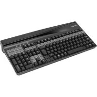
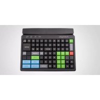
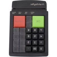
2 Characteristics of the MCI Family
The MCI family is characterized especially by its ergonomic and compact design.
Depending on the housing model, the keyboards of the MCI family are equipped with the following modules:
- glidepad or microjoystick,
- magnetic stripe reader (MSR),
- key-operated switch (KL),
- smart card read/write device (SCR).
Depending on the keypad model, keyboards of the MCI family have up to 128 (MCI 3100: 145) programmable key positions. In the alphanumeric keypad design, the keys of the alphabetic section are preassigned according to the functions of a standard MF2 keyboard.
Programming of the individual key positions and any integrated modules is done with our easy-touse programming software. You can find the appropriate software packages, as well as additional notes regarding programming, on the Internet under http://www.prehkeytec.com.
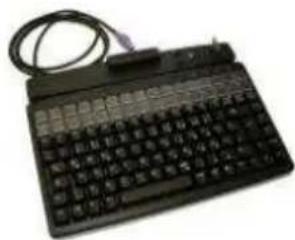
The figures in these operating instructions show the maximum configuration of the MCI 128. However, the description applies to all keyboards of the MCI family.
3 Installation
3.1 Contents of package
Before starting to use your keyboard, please check whether all the parts shown below are present and show no obvious signs of damage:
1 Operating Instructions and Technical Data
2 MCI family keyboard
2
Fig. 1 Contents of package
3.2 Installation of the keyboard
3.2.1 System requirements
The MCI family keyboard has been developed for use with IBM-AT-compatible PS/2 and USB systems. The keyboard can be used with all popular operating systems.
3.2.2 USB cable installation
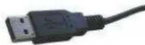
Fig. 2 USB plug
In order to provide problem-free operation of the keyboard using USB, it must be insured that the USB interface is supported by the operating system. This is the case for Windows 98SE and later, as well as Linux with a kernel version of 2.4.18 or higher.
In addition, insure that USB legacy support is activated in the BIOS of your system.
Please see the description of your motherboard for instructions regarding the BIOS settings.

The operating systems Windows 95, Windows NT and Windows 98 do not support the USB interface, or do so only partially. Problem-free operation is not insured in these cases.
Procedure
- If a keyboard is already connected to the computer, please remove it.
- Now insert the USB plug of the keyboard cable into an unoccupied USB socket.
- Now restart your system or switch it on. Certain drivers may be automatically installed by the operating system. The keyboard is then ready for use.
3.2.3 PS/2 cable installation (without glidepad/microjoystick)

Fig 3 PS/2 plug
Installation must be carried out when the computer is switched off. If a keyboard is already connected to the computer, please remove it.
Now insert the violet 6-pin mini DIN plug (Figure 3) of the keyboard cable into the keyboard socket provided on the computer. Insure that the poles are correct (coding pin).

Never force the keyboard plug into the PS/2 socket on the computer. This could result in bending of the connection pins - danger of short circuits!
3.2.4 PS/2 cable installation (with glidepad/microjoystick)
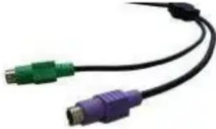
Fig.4 PS/2 Y-cable
Installation must be carried out when the computer is switched off. If a keyboard and/or mouse is already connected to the computer, please remove it.
First, insert the violet 6-pin mini DIN plug (Figure 4) of the keyboard cable into the keyboard socket provided on the computer (violet). Ensure that the poles are correct (coding pin).
Then insert the green 6-pin mini DIN plug (Figure 4) of the pointing device into the PS/2 mouse socket provided on the computer (green). Ensure that the poles are correct (coding pin).

Never force the keyboard plug into the PS/2 socket on the computer. This could result in bending of the connection pins - danger of short circuits!
3.2.5 Cable installation for smart card read/write device (USB / RS 232)
To connect the USB model, proceed according to section 3.2.2 USB cable installation.
Installation of the serial model must be carried out when the computer is switched off. Insert the 9-pin Sub-D connector (Figure 5) into an unoccupied serial interface on your PC (COM 1 to COM 4).
Now restart your system. The SCR module is now automatically detected. You can find further details regarding driver installation under http://www.prehkeytec.com.
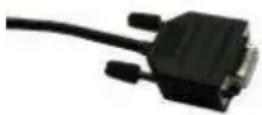
Fig. 5 SCR serial cable
3.2.6 Cable routing
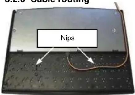
Fig. 6 cable nips
When it is delivered, the connection cable is routed on the right side (seen from above). If the cable outlet has to be moved to the left or center, you can do this quite easily.
Lay the keyboard with the keypad facing down on a soft surface. To move the cable outlet to the left, move the connection cable as shown in Figure 6. Ensure that the keyboard cable is firmly pressed into the nips provided.
3.2.7 Functional check
After you have started your computer, all four LEDs light up briefly. Then, depending on the status of the NumLock, CapsLock and ScrollLock, the associated LEDs light up. Your MCI keyboard is now ready for use.
4 Modules
4.1 Magnetic stripe reader (MSR)
All magnetic cards according to ISO 7810 and 7811 can be read. The magnetic stripe reader records the entire information content of the magnetic card. A LED signal (green Accept LED) is issued after a successful read procedure.
The magnetic card can be swiped through the reading device in both directions (Figure 7). This provides easy manipulation for both right- and left-handers.
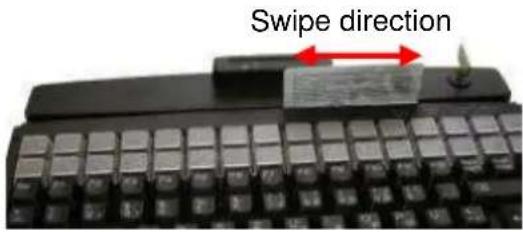
Fig. 7 Magnetic stripe reader
The parameters of the MSR can be set and/or modified using the corresponding PrehKeyTec programming software.
You can find further information, as well as the associated software, in the Internet under http://www.prehkeytec.com.
Important notice: Please hold the magnetic card near the upper edge during a swipe.
4.2 Keylock (KL)
The optional keylock (Figure 8) module has 5 positions and is supplied with 3 different keys.
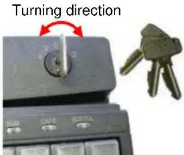
Fig.8Keylock
All keys can be inserted and removed in both positions 0 and 1. The following switch positions can be set with the three keys:
SUP key:01234
- REG key: 0 1
Xkey:012
By default, the code for the new switch position is transferred to the computer when the key is turned.
The parameters of the keylock can be set and/or modified using the corresponding PrehKeyTec programming software.
You can find further information, as well as the associated software, in the Internet under http://www.prehkeytec.com.
4.3 Smartcard read/write device (SCR)
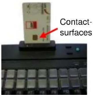
Fig. 9 SCR module
The EMV 3.1.1- and ISO 7816-certified SCR module of the MCI family allows you to read and write chip cards of types T = 0, T = 1, I^2C, 2-wire, 3-wire and PTS.
PC/SC drivers for the popular Windows operating systems (Windows 98 and higher) are available as the software interface. A CT-API interface can be placed on the PC/SC interface.
In order to read or write a chip card, carefully insert the chip card into the read slot; make sure that the chip contact surfaces face in the direction of the keypad (Figure 9). A slight click indicates that the end position has been attained. Reading or writing can now be carried out.
You can find further information, as well as the associated driver software, in the Internet under http://www.prehkeytec.com.
4.4 Pointing devices
With the optional microjoystick/glidepad, your MCI keyboard also has the functionality of a mouse. No additional driver for the operating system is required to operate the pointing devices.
The drivers for the corresponding pointing device (standard 2-button PS/2 mouse / standard 2-. button USB mouse) are installed automatically after the first start of the operating system. Thereafter, the microjoystick/glidepad is immediately ready for use.
4.4.1 Microjoystick
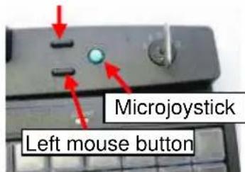
Right mouse button
Fig. 10 Microjoystick
Using the microjoystick (Figure 10), you can control the mouse arrow in the way that a mouse is used. Pressing the side of the microjoystick moves the mouse arrow in the corresponding direction. The stronger the pressure on the side, the faster the movement of the mouse cursor.
The two buttons to the left of the microjoystick correspond to those of a two-button mouse. The lower one is assigned to the left mouse button, the upper one to the right button.
4.4.2 Glidepad
The mouse arrow is controlled by moving your fingers on the glidepad surface (Figure 11). To do this, touch the glidepad with a fingertip and move your finger, pressing lightly, in the desired direction. The mouse arrow then follows the movement of your finger.
The two buttons below the glidepad correspond to those of a two-button mouse.

The glidepad is a capacitive system. It is not possible to operate the glidepad while wearing gloves or using other non-conducting objects.
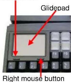
Left mouse button
Fig. 11 Glidepad
5 Additional Help
You can reach our Technical Support under:
Email: support@prehkeytec.de
Fax: +49 9776 / 7046-299
MCI Familie
Kurzanleitung
4.2 Schlüsselschalter (KL)
3.2.2 Raccordement USB

Photo 4 PS/2 Cable Y
Interface: USB 1.1 or IBM PC-AT, PS/2 and compatible systems
6.1.2 ESD and EMC behavior / ESD- und EMV-Verhalten / Conformité ESD- EMV
CE symbol
Unwanted emission EN55022, class B
FCCsubpart15classA
Immunity to interference immunity against high-frequency electromagnetic fields; penetration test value = 3V / m
immunity against electrostatic discharge according to EN 50082-1;
penetration test value = 8kV
6.1.3 Plug assignment / Steckerbelegung / Raccordement electrique

Fig.12.1 PS/2 plug
| PS/2 Mini-DIN 6pol. (male) keyboard / pointing device | |
| 1 Data | |
| 2 - | |
| 3 GND | |
| 4 +5V | |
| 5 Clock | |
| 6 - | |

Fig. 12.2 USB plug
| USB Plug A |
| 1 VCC |
| 2 -DATA |
| 3 +DATA |
| 4 GND |
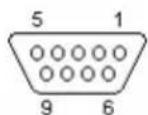
Fig. 12.3 RS 232 plug
| Sub-D 9pol. (female) SCR read/write device | |
| 1 - | |
| 2 TxD | |
| 3 RxD | |
| 4 DTR | |
| 5 GND | |
| 6 DSR | |
| 7 RTS | |
| 8 CTS | |
| 9 NC | |
6.1.4 Climatic parameters / Klimatische Parameter / Environnement
Temperature ranges
Storage/transport -40^ to +60^
Operation ± 0^ to +50^
Relative humidity 5% to 93%
Air pressure 700hPa to 1060 hPa
Climatic test category 0/050/21 according to DIN-IEC 68, part 1, appendix A
6.1.5 Mechanical system / Mechanik / Mécanique
Keys
Actuating force 0.6 N
Stroke strength 10N, 1 min.
Lifetime >3× 10 operations per contact element (typical value)
Keystroke 3.5mm
Grid spacing 19 mm
6.1.6 Protection class / Schutzart / Indice de protection
IP 54 according to DIN 40050/IEC 529
valid only for the keypad in the direction of actuation
Film-inegrat. circuit
polyester film
Sealing membrane
Trevira
Key caps
PBT/POM
Contact mat silicone rubber
7 Declaration of Conformity / Konformitätserklung / Certificate de conformité
This is to certify that all varieties of statements of compliance exist for MCI family.
Of course, you can request us to send you these if you provide the precise type designation (see the type label on the bottom of the device).
PrehKeyTec GmbH
Scheinbergweg 10
D-97638 Mellrichstadt, Germany
Fax: +49-9776 / 7046-299
FCC Warning Statement
NOTE: This equipment has been tested and found to comply with the limits for a Class A digital device, pursuant to Part 15 of the FCC Rules. These limits are designed to provide reasonable protection against harmful interference when the equipment is operated in a commercial environment. This equipment generates, uses and can radiate radio frequency energy, and, if not installed and used in accordance with the instruction manual, may cause harmful interference to radio communications. Operation of this equipment in a residential area is likely to cause harmful interference in which case the user will be required to correct the interference at his own expense.
Copyright
Copyright PrehKeyTec GmbH 2009
Published by PrehKeyTec GmbH.
PrehKeyTec GmbH reserves the right to update/modify the products described in this manual, as well as the manual itself, at any time without prior notice.
These operating instructions may not be copied, edited, transformed into electronic form or translated into other languages without prior written consent by PrehKeyTec GmbH.
Trademarks
The brand and product names mentioned in these operating instructions are trademarks / registered trademarks of the corresponding owner.
Examples:
Microsoft, Windows, Windows 95, Windows 98, Windows NT, Windows 2000, Windows XP are registered trademarks of Microsoft Corporation