
L208D251 - Voice recorder Lorex - Free user manual and instructions
Find the device manual for free L208D251 Lorex in PDF.
| Product Type | Digital Video Recorder (DVR) for surveillance system |
| Brand | Lorex |
| Model | L208D251 |
| Number of channels | 8 channels (BNC) |
| Recording resolution | NTSC : 640×224, PAL : 640×272 |
| Compression format | Motion JPEG (recording), MPEG4 (network) |
| Video outputs | 2 composite (BNC) + 1 VGA |
| Audio inputs | 1 RCA input |
| Storage | Internal hard drive up to 1 TB (2 × 500 GB) |
| Backup media | USB 2.0, CD/DVD-RW (optional) |
| Network connectivity | Ethernet 10/100, DHCP/Static/DDNS |
| PTZ control | RS-485, support for PTZ cameras |
| Alarm | 4 inputs / 1 output |
| Motion detection | Yes, adjustable by zone and sensitivity |
| Recording modes | Continuous, scheduled, motion detection, alarm |
| Remote control | Infrared included |
| Mouse | PS/2, supported |
| Power supply | External AC adapter (12 V DC) |
| Maintenance | Unplug before cleaning; use a damp cloth |
| Safety | Follow manual instructions (ventilation, overloading, etc.) |
| Client software | Lorex Client for remote viewing on PC (Windows 2000/XP) |
Frequently Asked Questions - L208D251 Lorex
User questions about L208D251 Lorex
0 question about this device. Answer the ones you know or ask your own.
Ask a new question about this device
Download the instructions for your Voice recorder in PDF format for free! Find your manual L208D251 - Lorex and take your electronic device back in hand. On this page are published all the documents necessary for the use of your device. L208D251 by Lorex.
USER MANUAL L208D251 Lorex
Includes L204 & L208
Copyright © 2008 Lorex Technology Inc.
Thank you for purchasing the L200 Series Surveillance DVR. Lorex is committed to providing our customers with a high quality, reliable security product.
The L200 series of Surveillance Digital Video Recorders provides professional grade features in a value package. Available in 4 and 8 channel models, the L200 series supports high quality video and audio recording, up to 1 Terabyte of internal data storage, optical drive (CD/DVD-RW) backup of critical video, USB back up and network support for local and remote viewing on a PC. This full featured series of DVRs also support composite and VGA output for viewing on any monitor, PTZ camera control, IR controller and PS/2 mouse navigation*.
To learn more about the L200 Series Surveillance DVR, and to learn about our complete range of accessory products, please visit our website at:
http://www.lorexcctv.com
- optional components - actual components may vary.

CAUTION
RISK OF ELECTRIC SHOCK DO NOT OPEN

CAUTION: TO REDUCE THE RICK OF ELECTRIC SHOCK DO NOT REMOVE COVER (OR BACK). NO USER SERVICABLE PARTS INSIDE. REFER SERVICING TO QUALIFIED SERVICE PERSONNEL.

The lightning flash with arrowhead symbol, within an equilateral triangle, is intended to alert the user to the presence of uninsulated "dangerous voltage" within the products 'enclosure that may be of sufficient magnitude to constitute a risk of electric shock

The exclamation point within an equilateral triangle is intended to alert the user to the presence of important operating and maintenance (servicing) instructions in the literature accompanying the appliance.
WARNING: TO PREVENT FIRE OR SHOCK HAZARD, DO NOT EXPOSE THIS UNIT TO RAIN OR MOISTURE.
CAUTION: TO PREVENT ELECTRIC SHOCK, MATCH WIDE BLADE OF THE PLUG TO THE WIDE SLOT AND FULLY INSERT.
Please visit us on the web for the most current Manuals, Quick Start Guides and Firmware.
Additional Language Manuals are also available at:
http://www.lorexcctv.com
Important Safeguards
In addition to the careful attention devoted to quality standards in the manufacture process of your video product, safety is a major factor in the design of every instrument. However, safety is your responsibility too. This sheet lists important information that will help to assure your enjoyment and proper use of the video product and accessory equipment. Please read them carefully before operating and using your video product.
Installation
- Read and Follow Instructions - All the safety and operating instructions should be read before the video product is operated. Follow all operating instructions.
- Retain Instructions - The safety and operating instructions should be retained for future reference.
- HeedWarnings - Comply with all warnings on the video product and in the operating instructions.
- Polarization - Do not defeat the safety purpose of the polarized or grounding-type plug.
A polarized plug has two blades with one wider than the other.
o A grounding type plug has two blades and a third grounding prong.
The wide blade or the third prong is provided for your safety.
- If the provided plug does not fit into your outlet, consult an electrician for replacement of the obsolete outlet
- Power Sources - This video product should be operated only from the type of power source indicated on the marking label. If you are not sure of the type of power supply to your location, consult your video dealer or local power company. For video products intended to operate from battery power, or other sources, refer to the operating instructions.
- Overloading - Do not overload wall outlets of extension cords as this can result in the risk of fire or electric shock. Overloaded AC outlets, extension cords, frayed power cords, damaged or cracked wire insulation, and broken plugs are dangerous. They may result in a shock or fire hazard. Periodically examine the cord, and if its appearance indicates damage or deteriorated insulation, have it replaced by your service technician.
-
Power-Cord Protection - Power supply cords should be routed so that they are not likely to be walked on or pinched by items placed upon or against them, paying particular attention to cords at plugs, convenience receptacles, and the point where they exit from the video product.
-
Ventilation - Slots and openings in the case are provided for ventilation to ensure reliable operation of the video product and to protect it from overheating. These openings must not be blocked or covered. The openings should never be blocked by placing the video equipment on a bed, sofa, rug, or other similar surface. This video product should never be placed near or over a radiator or heat register. This video product should not be placed in a built-in installation such as a bookcase or rack unless proper ventilation is provided or the video product manufacturer's instructions have been followed.
- Attachments - Do not use attachments unless recommended by the video product manufacturer as they may cause a hazard.
- Water and Moisture - Do not use this video product near water. For example, near a bath tub, wash bowl, kitchen sink or laundry tub, in a wet basement, near a swimming pool and the like.
Caution: Maintain electrical safety. Power line operated equipment or accessories connected to this unit should bear the UL listing mark of CSA certification mark on the accessory itself and should not be modified so as to defeat the safety features. This will help avoid any potential hazard from electrical shock or fire. If in doubt, contact qualified service personnel.
- Accessories - Do not place this video equipment on an unstable cart, stand, tripod, or table.
The video equipment may fall, causing serious damage to the video product. Use this video product only with a cart, stand, tripod, bracket, or table recommended by the manufacturer or sold with the video product.

Any mounting of the product should follow the manufacturer's instructions and use a mounting accessory recommended by the manufacturer.
Service
- Servicing - Do not attempt to service this video equipment yourself as opening or removing covers may expose you to dangerous voltage or other hazards. Refer all servicing to qualified service personnel.
- Conditions Requiring Service - Unplug this video product from the wall outlet and refer servicing to qualified service personnel under the following conditions.
A. When the power supply cord or plug is damaged.
B. If liquid has been spilled or objects have fallen into the video product.
C. If the video product has been exposed to rain or water.
D. If the video product does not operate normally by following the operating instructions. Adjust only those controls that are covered by the operating instructions. Improper adjustment of other controls may result in damage and will often require extensive work by a qualified technician to restore the video product to its normal operation.
E. If the video product has been dropped or the cabinet has been damaged.
F. When the video product exhibits a distinct change in performance. This indicates a need for service.
- Replacement Parts - When replacement parts are required, have the service technician verify that the replacements used have the same safety characteristics as the original parts. Use of replacements specified by the video product manufacturer can prevent fire, electric shock or other hazards.
- Safety Check - Upon completion of any service or repairs to this video product, ask the service technician to perform safety checks recommended by the manufacturer to determine that the video product is in safe operating condition.
- Wall or Ceiling Mounting - The cameras provided with this system should be mounted to a wall or ceiling only as instructed in this guide, using the provided mounting brackets.
- Heat - The product should be situated away from heat sources such as radiators, heat registers, stoves, or other products (including amplifiers) that produce heat.
Use
- Cleaning - Unplug the video product from the wall outlet before cleaning. Do not use liquid cleaners or aerosol cleaners. Use a damp cloth for cleaning.
- Product and Cart Combination - Video and cart combination should be moved with care. Quick stops, excessive force, and uneven surfaces may cause the video product and car combination to overturn
- Object and Liquid Entry - Never push objects for any kind into this video product through openings as they may touch dangerous voltage points or "short-out" parts that could result in a fire or electric shock. Never spill liquid of any kind on the video product
- Lightning - For added protection for this video product during a lightning storm, or when it is left unattended and unused for long periods of time, unplug it from the wall outlet and disconnect the antenna or cable system. This will prevent damage to the video product due to lightning and power line surges. The manufacturer's instructions and use a mounting accessory recommended by the manufacturer.
General Precautions
- All warnings and instructions of this manual should be followed
- Remove the plug from the outlet before cleaning. Do not use liquid aerosol detergents. Use a water dampened cloth for cleaning
- Do not use this unit in humid or wet places
- Keep enough space around the unit for ventilation. Slots and openings in the storage cabinet should not be blocked
- During lightning storms, or when the unit is not used for a long time, disconnect the power supply, antenna, and cables to protect the unit from electrical surge
FCCCLASSBNOTICE
Note:
This equipment has been tested and found to comply with the limits for a Class B digital device, pursuant to Part 15 of the FCC Rules. These limits are designed to provide reasonable protection against harmful interference in a residential installation. This equipment generates, uses, and can radiate radio frequency energy and, if not in-stalled and used in accordance with the instruction, may cause harmful interference to radio communications.
However, there is no guarantee that interference will not occur in a particular installation. If this equipment does cause harmful interference to radio or television reception (which can be determined by turning the equipment on and off), the user is encouraged to try to correct the interference by one or more of the following measures:
Reorient or relocate the receiving antenna
o Increase the separation between the equipment and receiver
o Connect the equipment into an outlet on a circuit different from that to which the receiver is connected
Consult the dealer or an experienced radio or television technician for assistance
This equipment has been certified and found to comply with the limits regulated by FCC, EMC, and LVD. Therefore, it is designated to provide reasonable protection against interference and will not cause interference with other appliance usage.
However, it is imperative that the user follows this manual' guidelines to avoid improper usage which may result in damage to the unit, electrical shock and fire hazard injury
In order to improve the feature functions and quality of this product, the specifications are subject to change without notice from time to time.

LOREX
LOREX TECHNOLOGY INC.
www.lorexcctv.com
L200 Series Features
4 or 8 Channel Triplex DVR (Simultaneously View, Record and Playback)
Network ready (LAN support with remote client application)
Efficient file transfer (MPEG4 network transmission)
Excellent original image recording (MJPEG recording to disk)
- Connects to any monitor (VGA and composite monitor support)
- Easy file backup (Supports optional internal optical drive, USB, remote client recording)
Large storage capacity (Supports 2 internal "security certified" disk drives up to 1TB total
Pan-tilt-zoom camera control (RS485 interface)
- Multiple recording modes (continuous, motion, alarm sensor, schedule)
- Adjustable frame rate for each channel (optimize recording characteristics)
Supports mouse navigation (easy operation)
- Alarm input-4/output-1 (connect to existing intruder alarm or alarm panel)
Connections:
- Up to 4 or 8 Cameras (depending on Model)
BNC Cable Connectors
Audio Input & Output -
Option for connection to any PC Monitor**
-
Software is only compatible with Windows 2000 / Windows XP
** L200 Series supports VGA Connection (PC Monitor).
Table of Contents
L200 Series - Front 9
L200 Series - Back 11
Remote Control 12
Mouse Control. 13
Camera Installation 14
InstallationWarnings: 14
Camera Stand Installation: 14
Connecting BNC Cameras 15
Camera Connection Diagram 15
Display Modes 16
Initial Loading Sequence 16
General Display Overview 17
Camera Display Modes 17
Onscreen Symbols - Channel Symbols 18
Onscreen Symbols - Status Bar 18
System Setup Controls 19
Menu Navigation Controls 19
Setup Menu - Options 19
System Menu Tree 20
RECORDING 34
SEARCH FUNCTION 35
SEARCH TYPES 35
SEARCH TYPES 36
VIDEO PLAYBACK 36
VIDEO PLAYBACK 37
BACK-UP VIA CD-R/W (OPTION) 38
FIRMWARE UPGRADE 39
PTZ (PAN/TILT-ZOOM) 40
Lorex Client Application 41
PLAYER MODE 42
VIEWER MODE 51
DVR Specifications - Appendix #1 60
Full Connectivity Diagram - Appendix #2 61
Hard Drive Replacement - Appendix #3 62
Troubleshooting - Appendix #4 64
Appendix #5 - Network Connectivity Overview 66
Appendix #6-PTZ Control 71
Appendix #7-Connecting Motion/Alarm Device 72
Appendix #8 - Initial Setup Menu Values 73
Getting Started
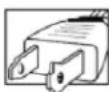
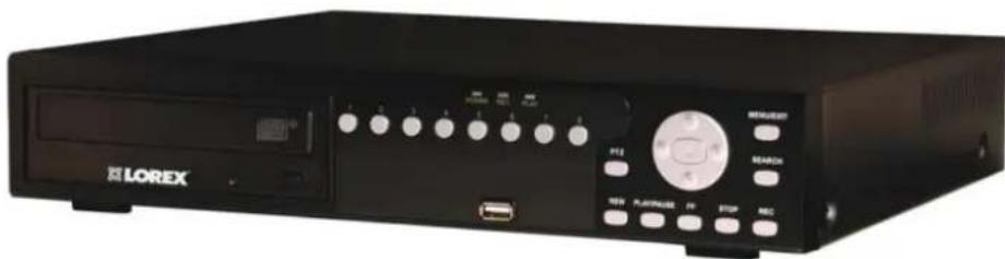
The DVR comes with the following components:
1 x COMPACT DIGITAL VIDEO REORDER (8 CHANNEL MODEL SHOWN)*

1x REMOTE CONTROL
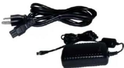
1x POWER ADAPTOR 1x POWER ADAPTOR CABLE
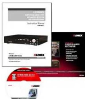
1x HARDWARE MANUAL 1x QUICK START GUIDE 1x SOFTWARE CD
*DVD-RW optional depending on model
CHECK YOUR PACKAGE TO CONFIRM THAT YOU HAVE RECEIVED THE COMPLETE DVR, INCLUDING ALL COMPONENTS SHOWN ABOVE.
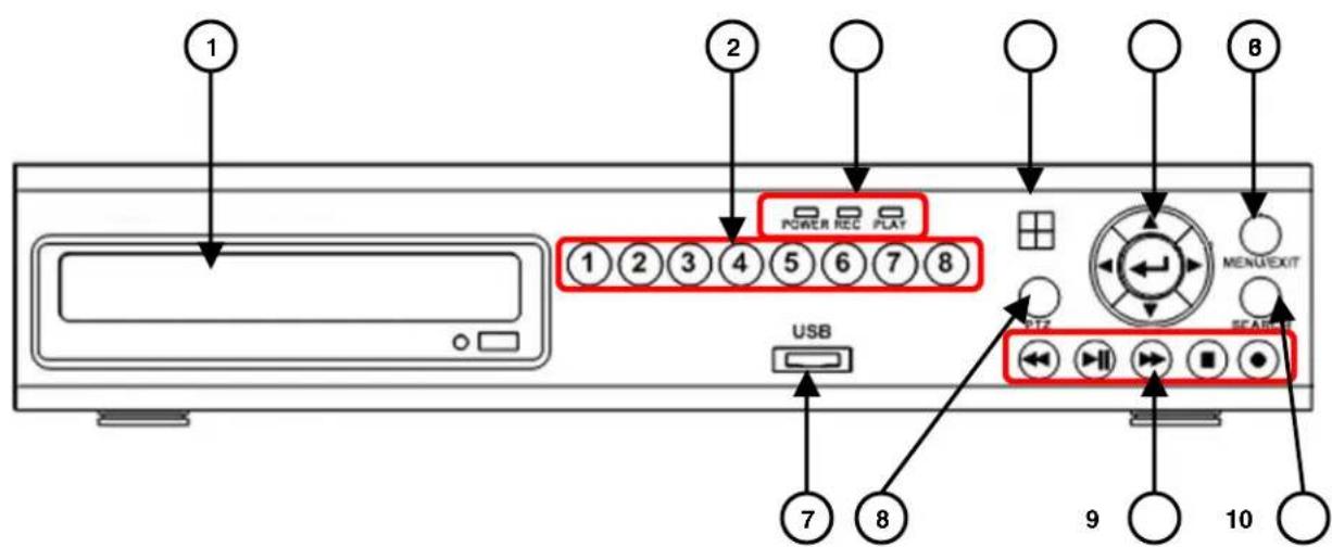
L200 Series - Front
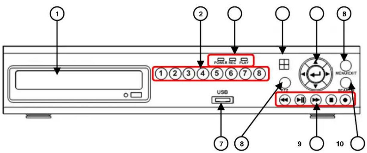
| 1 | CD-DVD-RW* |
| 2 | Channel Buttons |
| 3 | LED Indicators |
| 4 | IR Receiver |
| 5 | Navigation Control |
| 6 | Menu/Exit Button |
| 7 | USB Port 9 |
| 8 PTZ Button |
| Playback Controls | |
| 10 | Search Button |
- CD-DVD-RW DRIVE - *OPTIONAL: CD-DVD-RW drive optional depending on model.
-
CHANNEL DISPLAY - The channel buttons will display channels:
-
Channels 1~4 (L204 Series) - Press the 1~4 buttons to display the selected channel in full screen mode.
- Channels 1~8 (L208 Series) - Press the 1~8 buttons to display the selected channel in full screen mode.
- Channel 1 Button (L204 / L208 Series) - Press the Channel 1 button once to display Channel 1, and press it a second time to display Channels 1~4 in QUAD Display mode.
- Channel 5 Button (L208 Series) - Press the Channel 5 button once to display Channel 1, and press it a second time to display Channels 5~8 in QUAD Display mode.
3. POWER/REC/PLAYLEDs -
- POWER LED - The ORANGE POWER LED indicates that the unit is ON.
REC LED - The RED REC LED will blink, indicating that the unit is currently recording. -
PLAY LED - The GREEN PLAY LED will blink, indicating that previously recorded data is being played back on the unit.
-
IR RECEIVER - Receives the signal from the Remote Control
5. NAVIGATION CONTROLS/ENTER -
- Press the navigation controls to move Up, Down, Left and Right in the Main Menu and Search menus.
- Press the ENTER Button to select and change the values in a menu.
- Pressing the ENTER Button when displaying live video will change the onscreen view to 8 Channel View (L208 Series Only).

L200 Series - Front
| 1 | CD-DVD-RW* |
| 2 | Channel Buttons |
| 3 | LED Indicators |
| 4 | IR Receiver |
| 5 | Navigation Control |
| 6 | Menu/Exit Button |
| 7 | USB Port 9 |
| 8 | PTZ Button |
| Playback Controls | |
| 10 | Search Button |
^* CD-DVD-RW drive optional depending on model
- MENU/EXIT BUTTON - Press the MENU key to enter the System Menu. Press the button again to exit the System Setup or Search Menus.
- USB - One USB 2.0 port is provided to connect a USB flash drive to the DVR.
- PTZ BUTTON - Accesses the PTZ (Pan/Tilt/Zoom) Menu. Refer to Appendix 6 for Pan/Tilt/Zoom options
NOTE: The PTZ option will only work with PTZ type cameras (not provided with this unit). Visit the Lorex website at http://www.lorexctv.com for a full range of Pan/Tilt/Zoom Cameras.
- PLAYBACK CONTROLS - The Playback Controls have two sets of functions: Live View Functions and Menu Functions:
Live View Functions - Pressing the keys during Live View Mode will perform the following functions:
O Reverse-Opens the System Information window.
Play/Pause - Opens the Search Menu.
Fast Forward - Sets the Live View to Sequence Mode.
Record - Starts manual recording mode.
- Menu Functions - Pressing the keys when in the Main or Search Menus will perform the following functions:
Reverse - Reverses the playback of the selected Video (2x,4x,8x).
Play/Pause - Starts or Pauses the playback of the selected video.
Fast Forward - Fast Forwards the playback of the selected Video (2x,4x,8x).
o Stop - Stops the playback of video, and returns to the Live View screen.
Record - Starts manual recording mode.
- SEARCH BUTTON - Press the key to open the Search Menu
L200 Series - Back
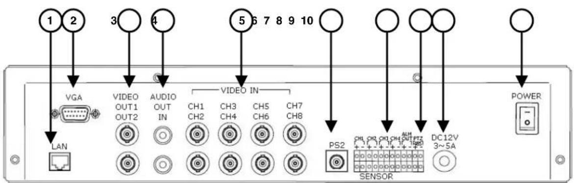
| 1 | LAN Port |
| 2 | VGA Port |
| 3 | Video OUT |
| Audio IN/OUT | |
| 5 | Video IN |
| 6 | PS/2 Port |
| 7 | Alarm Block | |
| 8 | RS-485/PTZ Block | |
| 9 | Power Input |
| 10 | Power Switch |
- ETHERNET CONNECTION - Connects the DVR to a router for connection to the Local Network and Internet.
- VGAVIDEO OUTPUT - Video Output port to connect the unit to a Computer Monitor. Directly reflects the current onscreen images.
- BNCVIDEO OUT (1 & 2) - Video Output ports to connect the unit to the video input of a TV or Observation System. Directly reflects the current onscreen images.
-
RCA AUDIO OUT/IN PORTS - Connection ports for Audio:
-
AUDIO OUT - Audio Output port to connect the unit to a TV or Observation System.
-
AUDIO IN - Connect One Audio input device such as a microphone to record Audio on one channel.
-
BNC VIDEO INPUTS - Channel 1~4 (L204 Series) -or- Channel 1~8 (L208 Series) camera inputs (used to connect Cameras with BNC connection type). Cameras with BNC connections require an additional power adapter.
- PS/2 PORT - Connection port for a PS/2 type mouse.
- ALARM FUNCTION TERMINALS (INPUT/OUTPUT) - These terminals are used to connect external alarm devices such as motion sensors or door/alarm sensors. Refer to Appendix 7 for Alarm Block Configuration.
- RS-485 / PTZ CAMERA TERMINALS - These terminals are used to control PTZ (Pan/Tilt/Zoom) type cameras. Refer to Appendix 6 for PTZ Configuration
- POWER INPUT - Connect to the DVR Power using the power cord provided with the unit. The power cable connects the DVR to an electrical outlet.
- POWER SWITCH - Turns the DVR ON or OFF.
Remote Control
Listed below is a quick reference for the Remote Control. All Buttons described above function the same as the Front Panel buttons.
- RE C BUTTON -Starts manual recording on the DVR.
- ONE FRM BUTTON - Not Used.
- CH4 BUTTON - Press to view QUAD2 (CH5~8 in L208 Series Only).
- QUAD/ENTER BUTTON - Press the ENTER Button to select and change the values in a menu. Pressing the ENTER Button when displaying live video will change the onscreen view to 8 Channel View (L208 Series Only).
- EVENT - Not Used.
- CH3 BUTTON - Press to switch through the channels from CH8~CH1.
- REV BUTTON - Opens the System Information window (in live view mode), and Reverses the playback of the selected Video (2x.4x.8x).
- PLAY/PAUSE BUTTON - Opens the Search Menu (in live view mode), and Starts or Pauses the playback of the selected video.
- STOP BUTTON - Stops the playback of video, and returns to the Live View screen.
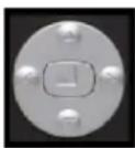
- SLOW (PTZ) BUTTON - Press to enter PTZ View Mode (if using a PTZ Camera). The PTZ diagram buttons correspond to the circle of buttons on the top of the remote.
- CH 1 BUTTON - Press to switch through the channels from CH1~CH8.
- MENU BUTTON - Press the MENU key to enter the System Menu. Press the button again to exit the System Setup or Search Menus.
- CH2 BUTTON - Press to view QUAD1 (CH1~4).
- TIME BUTTON - Opens the System Search menu (with the Backup Option available).
- FF BUTTON - Sets the Live View to Sequence Mode, and increase playback speed (2X, 4X, 8X)
- MUTE BUTTON - Mutes the Audio (it using an Audio enabled Camera on Microphone)
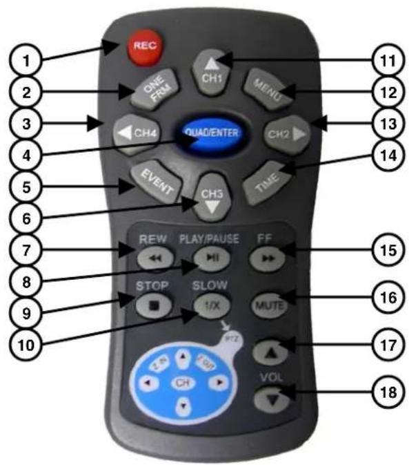
| 1 | RECORD | 10 | PTZ | MENU |
| 2 | Not Used> 11 VIEW CH1~CH8 | |||
| 3 | QUAD2 (CH5~8) | 12 | MENU / EXIT | |
| 4 | ENTER | 13 | QUAD1 (CH1~4) | |
| 5 | Not Used> 14 SYSTEM SEARCH | |||
| 6 | VIEW CH8~CH1 | 15 | FAST FORWAR | |
| 7 | REVERSE | 16 | MUTE AUDIO | |
| 8 | PLAY / PAUSE | 17 | VOLUME UP | |
| 9 | STOP | 18 | VOLUME DOWN | |
- VOL UP - Increases the volume of the Audio (if in use).
- VOL DOWN - Decreases the volume of the Audio (if in use).
Mouse Control
A mouse can be used with this DVR for Playback and Menu controls. Connect a mouse to the PS/2 port located on the back of the unit before powering the unit ON. Once the unit has loaded, the mouse will be recognized by the system.

Mouse Controls
DVR Setup
- The Setup window is displayed when the right mouse button is clicked in viewing mode.
- When the mouse is moved, the purple highlight box will switch between menu options.
- Click the left mouse button to access a menu selection
To change a setting, click the left button of mouse on the or icons displayed onscreen.
Once the setting has been changed, click the right mouse button to exit the menu.
DataPlayback
To use the Playback Options, first enter the System Setup menu as described above. To playback data, navigate to either:
Setup Search or
Setup System Event List
- Click the right mouse button during playback to control the video using the icons located on the lower left side of the screen.
- Find the desired starting date and time for backup, and press the button to select a starting point. The playback will go to the ending point for backup, then press button to select ending point. Select [USB] or [CD] to move start the video backup.
NOTE: Recording must be stopped prior to starting the backup.
Advanced Reservation Record using a mouse
- Recording can be set for a desired time period using a mouse. Navigate to: Set-up Record Record Schedule
- Set the desired time period and date, and click the mouse to backup data.
Viewing Screen Control
- You can change the view on the Live Viewing screen using the mouse. On the viewing screen double click the left mouse button on the desired channel screen to switch to full screen view.
- Double click again to return to the QUAD View Screen.
Camera Installation
Before you install the camera*, carefully plan where and how it will be positioned, and where you will route the cable that connects the camera to the DVR.
InstallationWarnings:
- Select a location for the camera that provides a clear view of the area you want to monitor, which is free from dust, and is not in line-of-sight to a strong light source or direct sunlight.
- Plan the cables' route so that it is not close to power or telephone lines, transformers, microwave ovens or other electrical equipment that could interfere with the DVR.
- Select a location for the camera that has an ambient temperature between 14^ 113^ (-10^ 45^)
- If you plan to install the camera in a location that has conditions not recommended in this manual, consult with a professional installer and consider use of a separate camera cover or housing
Before starting permanent installation, have another person hold the camera for you while you verify its performance by observing the image on a monitor.
Camera Stand Installation:
- Attach the pedestal to the ceiling, wall or other surface by the base using the provided screws.
- The mounting bracket must be attached to a structural device such as a wall stud or ceiling rafter using the supplied screws.
- Attach the camera to the pedestal. Adjust the angle of the camera, and tighten the thumbscrew to set the position
NOTE: The Camera can be attached to the stand using the screw point on the top or the bottom (to maintain proper camera alignment). This prevents the image from becoming inverted.
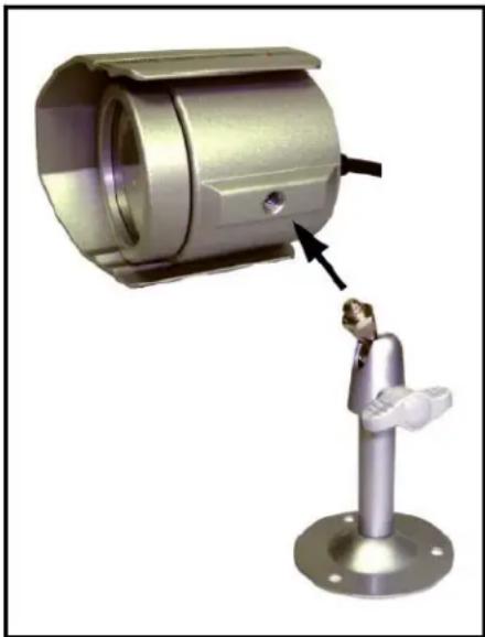
* Camera may not be exactly as shown
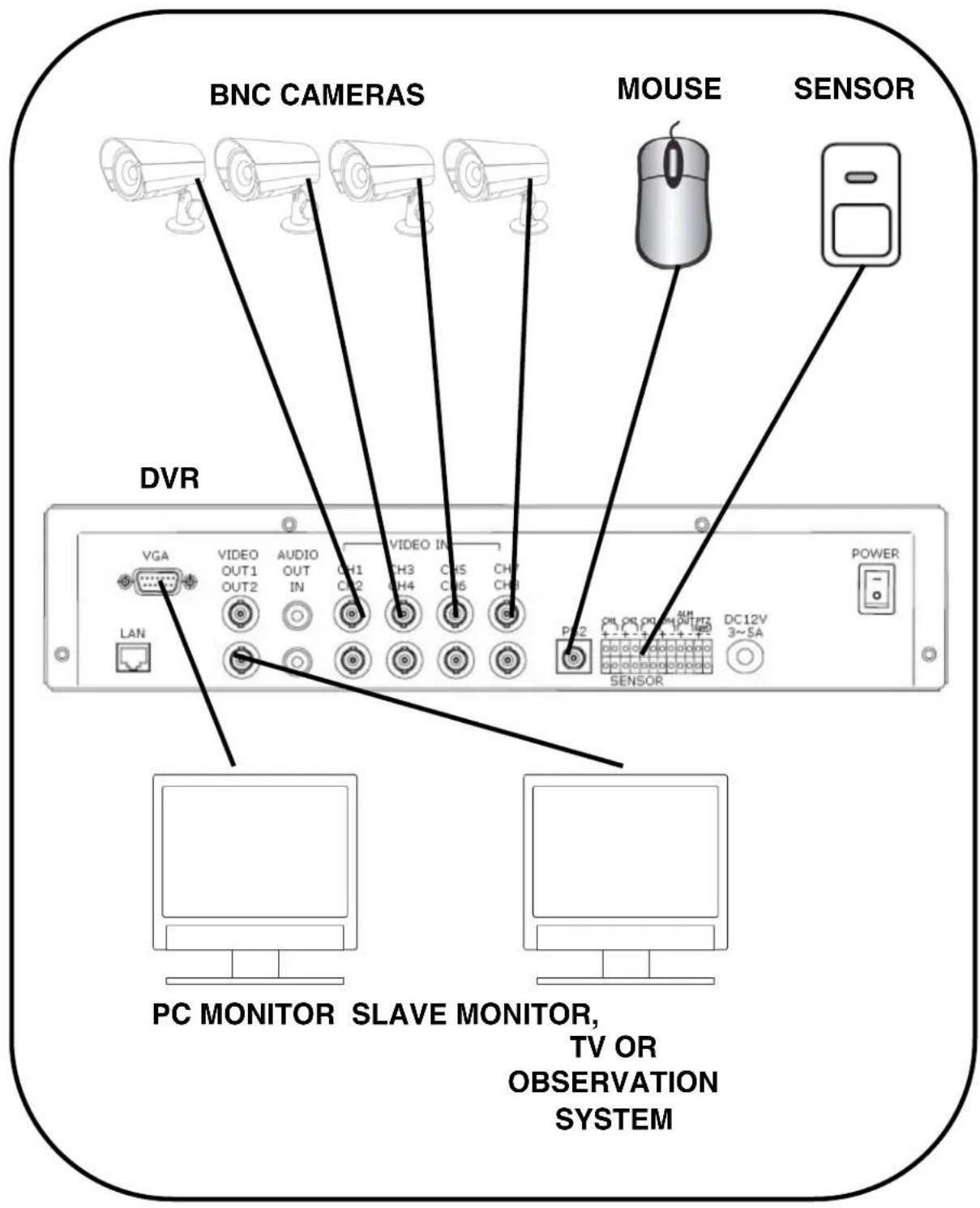
Connecting BNC Cameras
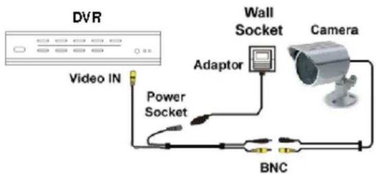
- Connect the 60ft Extension cable to the Camera and DVR:
A. Connect the Barrel Power connector to a power adaptor.
B. Connect the BNC connector to an available BNC Port (CAM 1~4) on the DVR.
C. Connect the Male Power connector to the Camera.
D. Connect the BNC connector to the Camera.
- Connect the Power Adaptor to a wall outlet.
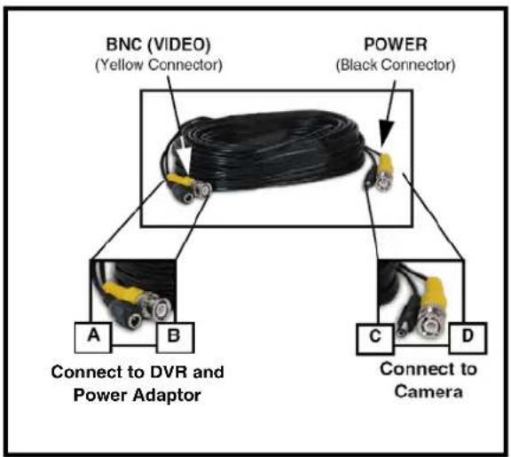
IMPORTANT NOTE: The ends of the extension cable are NOT the same - one end has a Male power port, and the other has a Female power port. Before permanently running the Camera Extension Cable, make sure that the cable has been oriented between the Camera and the unit correctly.
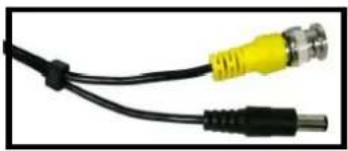
Male Power Port - The male power port end of the Extension cable connects to the Camera.
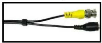
Female Power Port - The female power port end of the Extension cable connects to the Power Adaptor.
Camera Connection Diagram
Display Modes
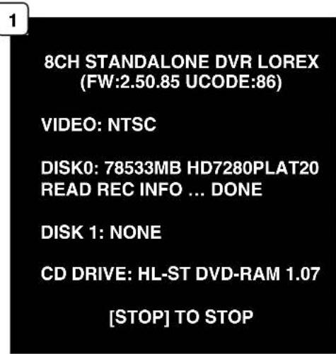
Initial Loading Sequence
The unit will automatically begin loading when power is connected to the DVR, and the ON/OFF button on the back of the unit is switched to ON.
- The DVR will perform a Firmware check. During the loading sequence, the following information will be displayed:
4 or 8 Channel DVR and Firmware Version
Video Type: NTSC or PAL
- Disk0 Check: Displays information about the connected Hard Drive
- Read Info: Checks previously recorded data
- Disk1 Check: Displays information about a second hard drive (not available in this model).
- CD-Drive: Displays information about the connected CD/DVD Drive.
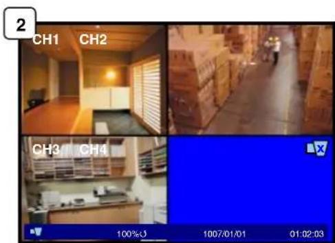
- The unit will initially load to a split screen view, displaying all 4 or 8 cameras (depending on model) with Camera Names and Recording Status. The Drive Full, Date and Time are displayed in the bottom bar. If a camera cannot be displayed, a Video Loss Icon appears, and the channel will display a blank blue screen instead of an image.
NOTE: If a new HARD DRIVE is detected, the system will prompt you to FORMAT the drive. If you do not choose to format the HARD DRIVE, the drive will not be detected by the system.
If you choose to FORMAT a drive in this way, the drive will no longer be readable by a regular PC.
Press the PLAY button to format the drive, or pres the STOP button to cancel the format.
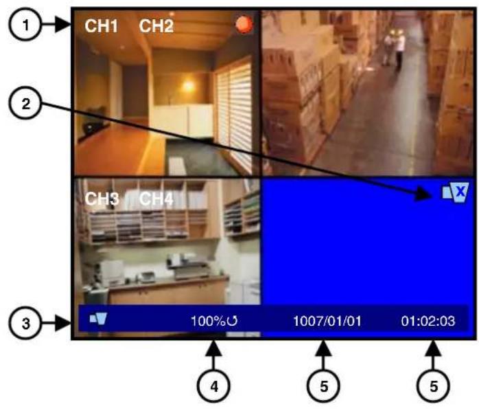
General Display Overview
1.CAMERA TITLE & RECORDING
STATUS - Displays the Camera Name (Up to 8 Characters) and Displays the current Recording Status (if the System is recording the symbol appears).
2.VIDEO LOSS ICON - Appears when the Camera is not sending a Video Image.
4.DRIVE FULL INDICATOR -
Indicates the amount of drive space available (100% indicates full). If the circle with arrows () is displayed the DVR is in Overwrite Mode.
- DATE - Displays the current Date for the DVR.
- TIME - Displays the current Time for the DVR.
Camera Display Modes
Cameras can be displayed in Single Channel, QUAD1, QUAD2, 8CH-Split or Sequence Modes.
- The DVR defaults to Quad view when first loaded.
- Press the Channel Buttons to display a single channel.
- Press the CH1 Button again to display QUAD1 (CH1~CH4), or press the CH5 Button again to display QUAD2 (CH5~CH8)
- Press the FF (Fast Forward) button to display all cameras in a rotating sequence mode (3 second view per channel by default).
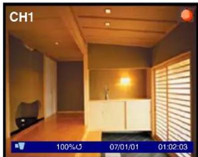
SINGLE CHANNEL VIEW - Press the corresponding Channel Number to view.
QUAD1 (CH 1~4) - Press the CH1 button to display the Quad View.
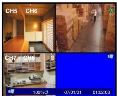
QUAD2 (CH 5~8) - Press the CH5 button to display the Quad View.
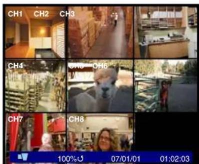
9-CHANNEL VIEW - Press the ENTER Button to display all cameras (L208 Series)
Onscreen Symbols - Channel Symbols
The following symbols appear on a channel to indicate the status of the channel:

Indicates that the channel is currently Recording video.

Indicates that Motion has been detected on the channel.

Indicates that a Sensor (Alarm) has been signaled on the channel.

Indicates that there is no video signal coming from the camera.
Note: If the screen is blue and not displaying this symbol, check the camera connection.
Onscreen Symbols - Status Bar

Indicates that DVR is in monitoring mode.

Indicates that a network user is connected to the system.

Indicates that alarm on system has been activated.

Displays the amount of space used on the Hard Drive.

Indicates that the DVR is in continuous recording mode.

te: Data will be overwritten when the drive is full.
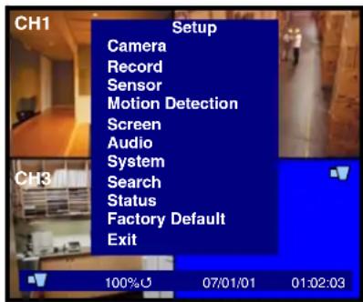
System Setup Controls
- Enter the SYSTEM MENU screen by pressing the MENU/EXIT button. Enter the password to display the Menu Selection Screen.
- Scroll through the 11 options by pressing the UP & DOWN (▲▼) buttons on the Front Panel or Remote Control.
- To enter a sub-menu, navigate to the option (indicated by the Purple Hightlight) and press the ENTER Button () .
- To exit a SUBMENU, press the MENU/EXIT button.
- To change the options, press the RIGHT and LEFT buttons () .
- To exit the MAIN MENU, press the MENU/EXIT button. If system changes were made, a prompt will appear to Save Changes when exiting the menu.
Menu Navigation Controls

- MENU/EXIT Button - Accesses the setup menu, and returns to previous menu options.
- ENTER Button () - Enters a Menu setting
- UP / DOWN Controls (▲▼) - Move Up/Down through the Menu Options.
- LEFT / RIGHT Controls (▲▶) - Move Left / Right to change the Menu Settings.
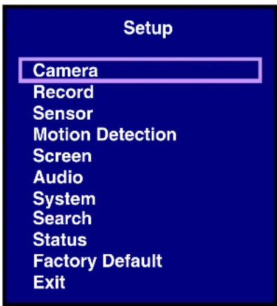
Setup Menu - Options
The Setup Menu has11 options:
- CAMERA - The camera menu contains the individual camera image settings.
- RECORD - This menu contains the recording settings for Scheduled recording.
- SENSOR - This menu contains the configuration settings for Sensors connected to the DVR Alarm block.
- MOTION DETECTION - Controls the Motion Settings for each channel, including motion detection area
- SCREEN - Contains the settings for the DVR Display and Sequence
- AUDIO - This menu controls the Audio Recording, Input and Output
- SYSTEM - Contains the System Settings, including Hard Drive, Password, Time and Date Settings, Network, PTZ Setup and Firmware Upgrading
SEARCH-Search the drive for previously recorded video and events
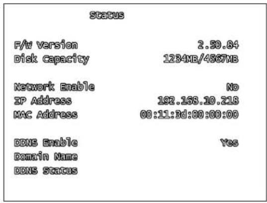
STATUS - Displays the system settings
FACTORY DEFAULT - Restores Factory Defaults - EXIT - Returns to the main viewing screen
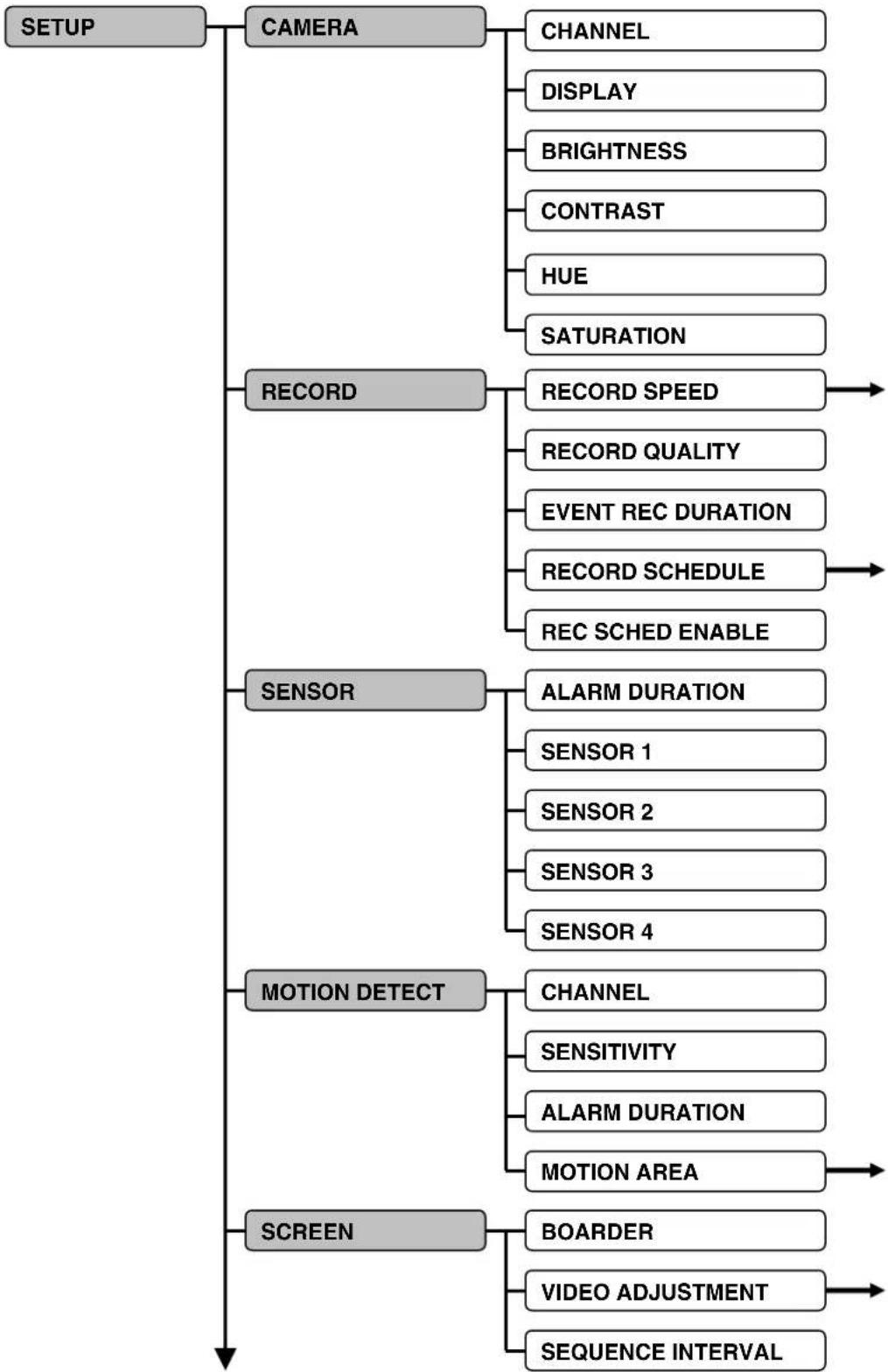
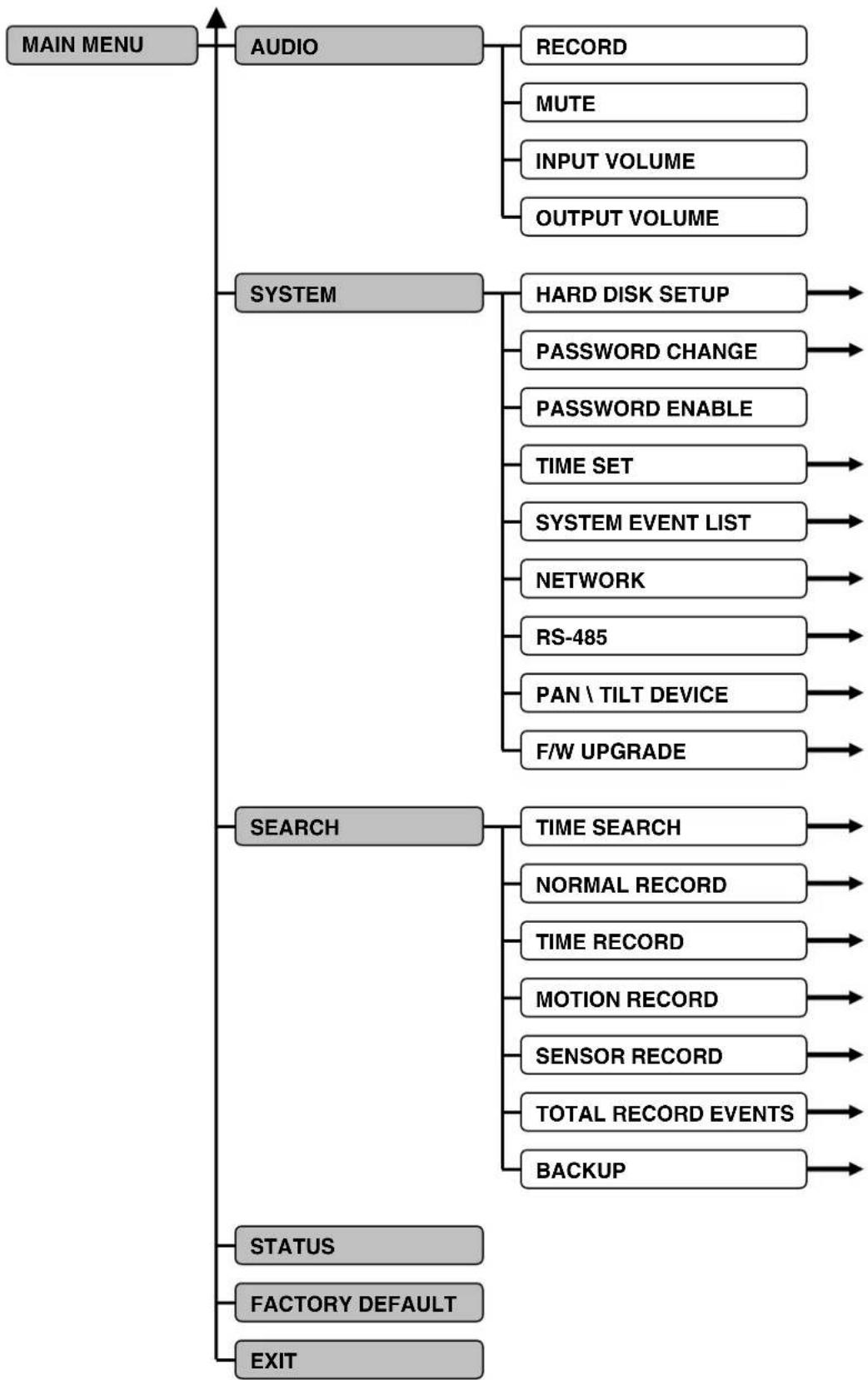
System Menu Tree
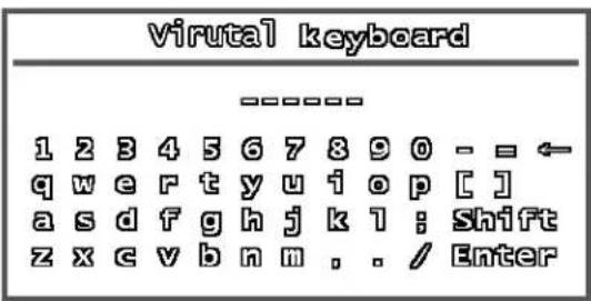
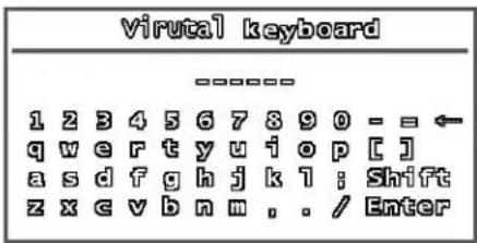
Using the Virtual Keyboard
The Virtual Keyboard control becomes available when keyboard input is needed for entering information such as Names, Network Information, etc.
- Includes a~z, A~Z, 0~9 and Symbols: !@#$%^&*(_+{}<?=[:,/
- Navigate using the arrow keys on the Front Panel or Remote Control.
- Use the ENTER Button to choose the letters, numbers and symbols
- Press the Menu/Exit button once the setup is completed
CAMERA SETUP
The CAMERA SETUP controls the display settings for each Channel on the DVR.
Use the arrows to navigate through the settings, and the arrows to change the values. Press the MENU/EXIT button to return to the previous menu.
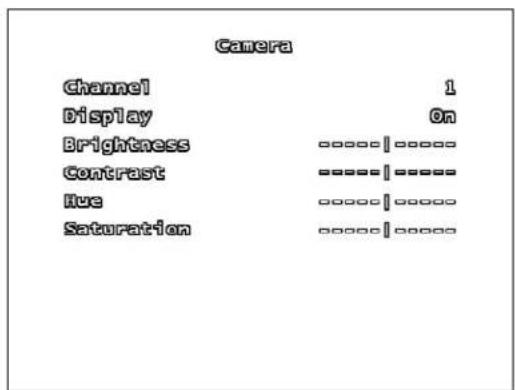
CHANNEL
Switch between CH1~CH4 (L204 Series) or CH1~CH8 (L208 Series) to change the settings for the individual channel.
DISPLAY
Set the onscreen display of the camera to ON or OFF (Covert Camera). If the camera is in Covert (not displayed), it will continue to record as normal.
BRIGHTNESS
Set the brightness of the image by setting the value between 1 (darkest) to 10 (brightest). Move the slider bar left or right to change the brightness setting.
CONTRAST
Set the contrast of the image by setting the value between 1 (lowest) to 10 (highest). Move the slider bar left or right to change the contrast setting.
HUE
Set the hue of the image by setting the value between 1 (pale) to 10 (deep). Move the slider bar left or right to change the hue setting.
SATURATION
Adjust the color richness of the display. Move the slider bar left or right to change the saturation setting.
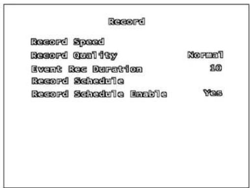
RECORD SETUP
The Record Setup controls the settings for Recording for the DVR.
Use the arrows to navigate through the settings, and the arrows to change the values. Press the MENU/EXIT button to return to the previous menu.
The Record Speed Submenu controls the Frames per second (FPS) used for each channel.
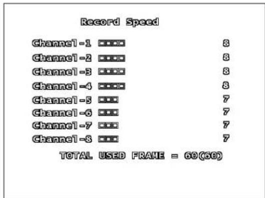
(L208 Series menu shown)
The total available Frame Rate is 60 FPS. These frames are shared across all channels, and can be divided according to channel importance.
For example, a camera pointed at the front door may require a higher frame rate (i.e. 15 FPS) than a camera that is monitoring a low traffic area (i.e. 7 FPS).
RECORD QUALITY
Set the RECORD QUALITY to LOW, NORMAL or HIGH. This setting is the same for all channels.
- With a higher Recording Quality, the image will appear clearer during playback; however more storage space will be required on the Hard Drive to save the video.
- With a lower the Recording Quality, the image will appear less clear during playback; however less space storage space will be required on the Hard Drive to save the video.
EVENT REC DURATION
Set the Recording Duration when an EVENT (sensor / motion) is detected on the system. Set the duration to 5, 10, 15, 20, 25 or 30 seconds.
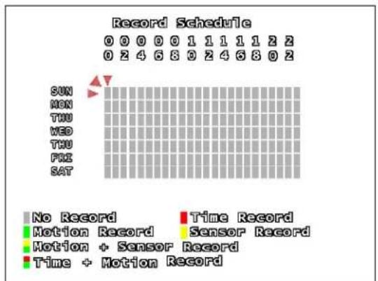
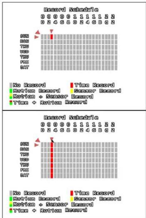
RECORD SCHEDULE SUBMENU
The Recording Schedule is based on a 24-hour clock, and each hour can be set for a different recording type.
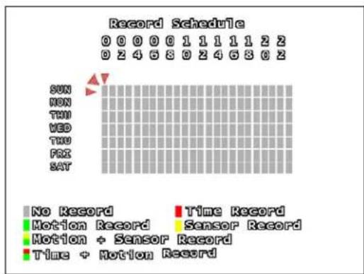
RECORD SCHEDULE
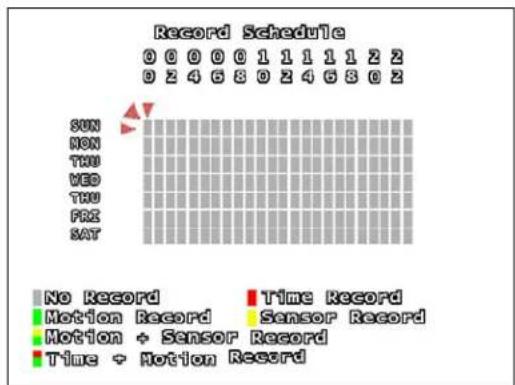
Move cursor to the desired time using the
arrows, and press the ENTER
Button to scroll through the available recording settings:
- No Record - The System will not record video during this period.
Time Record - The System will record data continuously during this period.
Motion Record - The System will record data only when the camera recognizes motion in a designated area during this period. - Sensor Record - The System will record data only when an sensor or alarm is signaled during this period.
Motion + Sensor Record - The System will record data when either Motion or a Sensor/Alarm is detected.
Time + Motion Record - The System will continuously record data during this period. If motion is detected during this time, the video will be flagged in the system as a Motion Event. - To set the entire line (all hours in a day) to the same recording type, set one square in the day to the desired recording type. Remain on that square, and press the Record - Button.
To set all days to the same recording type, use the mouse to set the top left corner (Sun 0hr) to the desired recording type, and click on the red diagonal arrow (to the upper left of the square).
RECORD SCHEDULE ENABLE
Sets the Recording Schedule to ON or OFF.
NOTE: It is important to leave this setting to ON. If this setting is turned OFF, the DVR will NOT record any data (Manual Recording (when the REC Button is pressed) will override the Record Settings, and immediately begin recording.)
SENSOR SETUP
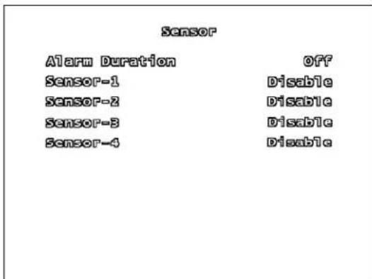
ALARM DURATION
Determines how long an alarm lasts after detection. Settings include: OFF, 05, 10, 15, 20, 25, 30 Seconds or CONT (continuously).
If there are no sensors connected to the DVR, set the Alarm Duration to OFF.
SENSOR - 1, 2, 3, 4
Set the type of sensor installed for CH1~CH4. The settings include: DISABLE (none), Normally Open (NO) or Normally Closed (NC).
MOTION DETECTION SETUP
The Motion Detection Setup controls the behavior of the DVR when Motion is detected.
Use the arrows to navigate through the settings, and the arrows to change the values. Press the MENU/EXIT button to return to the previous menu.
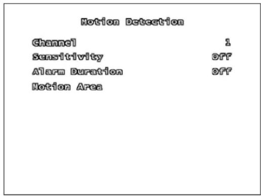
CHANNEL
Switch between CH1~CH4 (L204 Series) or CH1~CH8 (L208 Series) to change the settings for the individual channel.
SENSITIVITY
This setting adjusts the sensitivity of the pixel based motion detection on the DVR. Set the option from 1 (low sensitivity) to 4 (high sensitivity) or OFF.
ALARM DURATION
Determines how long an alarm lasts after detection. Settings include: OFF, 05, 10, 15, 20, 25, 30 Seconds or CONT (continuously).
If there are no sensors connected to the DVR, set the Alarm Duration to OFF.
MOTION AREA SUBMENU
Use the Motion Detection area to determine which areas of the image will detect motion. Areas shaded with a darker color indicate that the area is selected to detect motion.
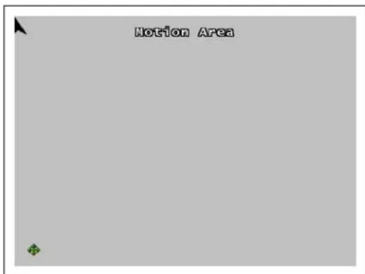
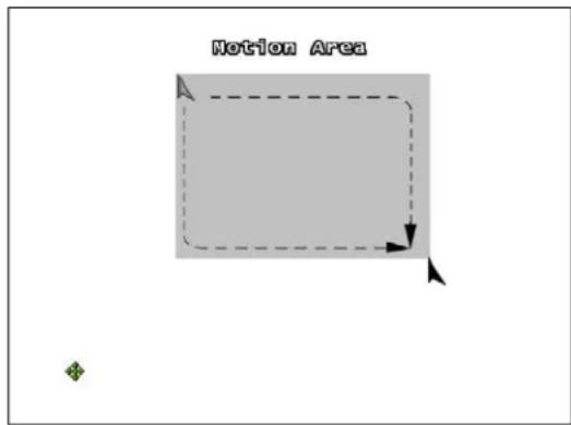
Using the Front Panel Buttons:
- Use the front panel arrows to navigate to the desired starting location.
- Press the Enter button once. Use the arrows to drag the block to the desired area coverage.
- Press the Enter button to stop setting the motion area.
NOTE: Only one blocked section can be set on the Detection Area. Multiple selections cannot be added.
Using a Mouse:
- Press and hold the left mouse button
- Drag to select the detection area
NOTE: Click the arrow icon to set the entire area for motion detection.
SCREEN SETUP
The Screen Setup controls the onscreen display of the DVR.
Use the arrows to navigate through the settings, and the arrows to change the values. Press the MENU/EXIT button to return to the previous menu.
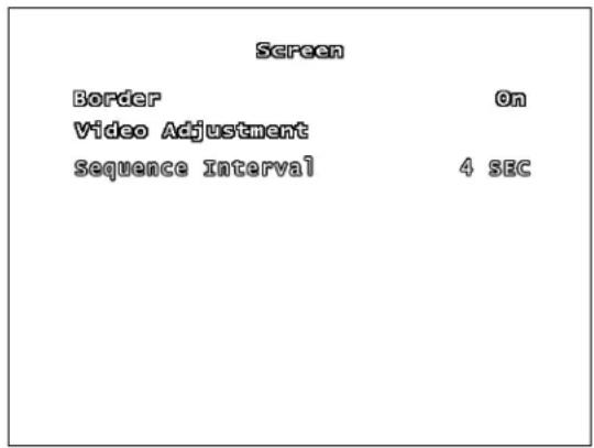
BORDER
The border is the white line that appears around each channel. Set the option to ON (displays the border) or OFF (no border).
VIDEO ADJUSTMENT SUBMENU
Use the Video Adjustment to change the position of the entire screen, using the arrow keys.
SEQUENCE INTERVAL
Set the length of time that each channel will be displayed in full screen during Sequence Mode. The sequence interval can be set between 0 seconds to 7 seconds.
NOTE: Press the FF Button on the front panel to enter Sequence Mode when viewing live video.
AUDIO SETUP
The Audio Setup adjusts the Audio input/output of the DVR system.
Use the arrows to navigate through the settings, and the arrows to change the values. Press the MENU/EXIT button to return to the previous menu.
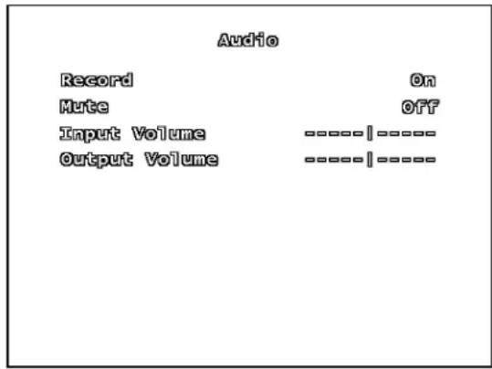
RECORD
Set Record to ON to enable sound recording (when a microphone is attached into the AUDIO INPUT port on the system).
NOTE: The audio is shared across the entire system, and cannot be set for a specific channel (i.e. if an audio device is connected near Channel 4, the same audio will be recorded on all channels).
MUTE
Set the system mute ON or OFF.
INPUT/OUTPUT VOLUME
Adjust input and output volume levels. Move the slider bar left (low volume) or right (high volume) to change the volume setting.
SYSTEM MENU
The System Setup controls many aspects of the functionality in the DVR, including the Password, Time and Date, Network and PTZ setup.
Use the arrows to navigate through the settings, and the arrows to change the values. Press the ENTER button to enter a submenu, and press the MENU/EXIT button to return to the previous menu.
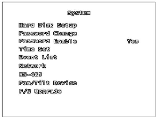
HARD DISK SETUP SUBMENU
The Hard Disk Setup contains information about the installed Hard Drive (Total Hard Drive Space, and Space Used), and allows the user to Set the Overwrite and Format the drive.
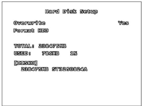
OVERWRITE - If the Overwrite option is set to Yes, when the Hard Drive becomes full the system will begin overwriting the older information. If Overwrite is set to No, then the DVR will stop recording when the Hard Drive becomes full.
FORMAT HDD - Formatting the Hard Drive erases all stored video data (firmware settings are not erased). When you choose to Format the drive, the system will prompt you for the password before formatting (The default password is [111111]).
NOTE: Once the drive has been formatted, you will no longer have access to the previously recorded data, and there is no recovery.
password CHANGE SUBMENU
The Password Change submenu allows the user to change the system password.
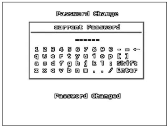
Any combination of buttons on the front panel of the DVR can be used in the new password. Enter the new characters, and press the Enter button to finish.
A Password Changed message will be shown on screen when the password is successfully changed in the system.
password ENABLE
The Password Enable feature turns the use of a system password ON or OFF. If the option is set to YES, the password is required when entering the Setup Menu, Resetting Factory Defaults, Using the PTZ and Stopping video recording.
TIME SET SUBMENU
The Time Set menu controls the date and time for the DVR.
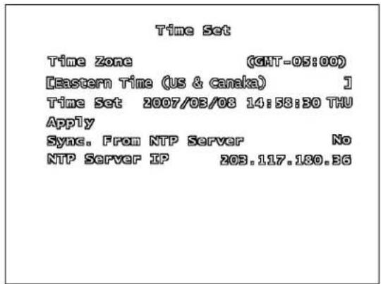
TIME ZONE - Set the current time zone by scrolling through available options (GMT based timezones).
TIME SET - Use the arrows to adjust the Date and Time (YYYY/MM/DD HH:MM:SS). Press the Menu/Exit button to finish changing the settings.
- APPLY - Select the Apply option and press the ENTER button to save the changes to the date and time.
SYNC. FROM NTP SERVER Synchronizes the system with a Network Time Server (over the Internet) to set the date and time. An internet connection is required.
- NTPSERVER IP - Enter the IP address of the Time Server. The default value time server IP is 203.117.180.36.
SYSTEM EVENT LIST SUBMENU
The Event List provides a detailed listing of the events that have occurred in the system.
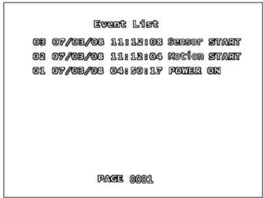
The Event List includes:
DVR Power ON/OFF
- Recording Start / Stop
- Sensor ON/OFF
Motion Detection
- Timed Recording Start / Stop
The list is displayed by Event Number, Date, Time and Event type.
Navigate through the events using the arrow buttons.
To Playback a valid event, select the event from the list and press the ENTER button.
NETWORK SUBMENU
The information in the Network menu allows users to remotely access the DVR.
| Network Settings | |
| Enable | Yes |
| Local Ip | |
| Port | 6841 |
| Mac Address | 12:24:56:78:9A:BC |
| Password | 111111 |
| DNS Setup | |
| Video quality | High |
ENABLE - Set Enable to YES to remotely connect to the DVR over a network connection. If this option is set to NO, remote access to the system will be disabled.
LOCAL IP MENU - The Local IP menu contains the IP Address and other networking information.
| Local IP | ||||
| IP Type | [DUGP] | |||
| IP Address | 0. | 0. | 0. | 0 |
| Gateway | 0. | 0. | 0. | 0 |
| Net Mask | 0. | 0. | 0. | 0 |
- IP TYPE - The IP Type determines how the Network Information is entered into the DVR. There are three network connection types:
DHCP - The network automatically leases the information to the DVR
Static - Enter the information manually based on the connected network
DHCP SETUP
| Local IP | ||||
| IP Type | [DUGP] | |||
| IP Address | 0. | 0. | 0. | 0 |
| Gateway | 0. | 0. | 0. | 0 |
| Net Mask | 0. | 0. | 0. | 0 |
NOTE: The Local Network will lease the information to the DVR. The user is not required to complete these fields.
- IP Type: DHCP
The information for the IP Address, Gateway and Net Mask will be automatically provided by the Local Area Network.
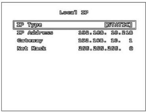
STATIC SETUP
| Local IP | |
| IP Type | [STATIC] |
| IP Address | 192.168.10.213 |
| Gateway | 192.168.10.1 |
| Net Mask | 255.255.255.0 |
NOTE: Gather the Network Information from the Network Router prior to changing these settings.
- IP Type: Static
- IP Address: Enter an IP address that is not currently in use on the local network.
- Gateway: Enter the Gateway for the local network.
- Net Mask: Enter the Subnet Mask information for the local network.
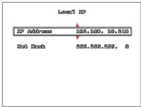
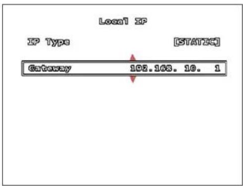
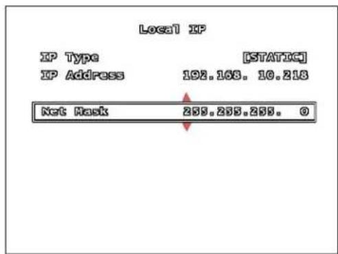
STATIC SETUP
Use the arrow buttons to change the Network Settings:
12
34
NETWORK SUBMENU (CONT.)
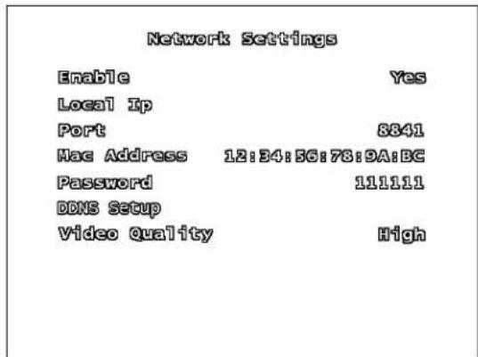
PORT - The Port Information is required for remote access. The default port for the DVR is 8841. Please refer to the Port Forwarding section of this manual for details.
MAC ADDRESS - The Mac Address is the unique physical address set by manufacturer, which is necessary for DDNS network connection. Do not change this value.
PASSWD - A Password is required for network connection. Set the password using the buttons on the front panel.
DDNS SETUP MENU - The DDNS Setup menu contains the configuration settings for remote access via the Lorex DDNS Service (http://ddns.strategicvista.net).
A DDNS Service updates the remote connection information, and is useful when the IP Address frequently changes.
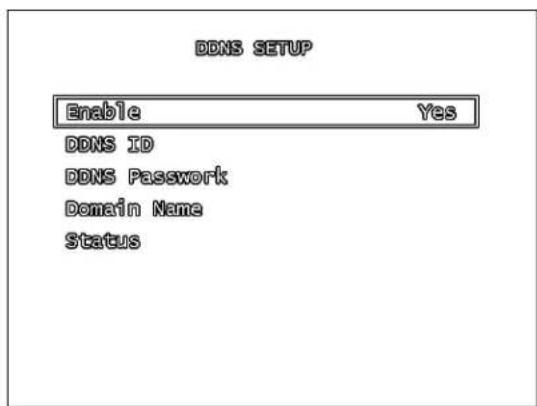
DDNS SETUP
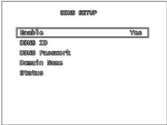
- Enable: Set to YES if using the DDNS Service. DDNS ID: DDNS SERVER SET-UP (ENABLE): Select "YES" in name server set-up.
- DDNS ID: Enter the name from the DDNS Registration using the virtual keypad. Press ENTER once complete.
- DDNS PASSWORD: Enter the password from the DDNS Registration using the virtual keypad. Press ENTER once complete.
- DOMAIN NAME: Enter the domain name from the DDNS Registration using the virtual keypad. Press ENTER once complete.
NOTE: Do not enter the entire DDNS address (i.e. myurl.strategicvista.net) - only the first part of the address should be entered (i.e. myurl from the example above).
STATUS: Displays the status of the DDNS Connection. A Success message indicates that the network connection has been established.

RS-485 SUBMENU
The information in the RS-485 submenu allows users to configure the settings for an RS-485 Device.
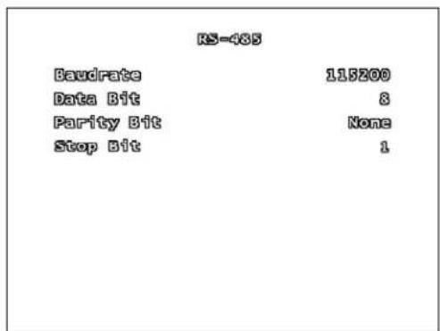
NOTE: The configuration settings for this section would be provided with the documentation included with the RS-485 device.
BAUDRATE: Set the Data Transmission (Baud rate) to 1200, 1800, 2400, 4800, 9600, 14400, 19200, 36400, 57600 or 115200 bps.
DATA BIT: Set the Data Transmission Bit to 7 or 8.
- PARITY BIT: Set the Data Transmission Error Check Bit to odd, even or none.
- STOP BIT: Set the Data Transmission Stop Bit to 1 or 2.
PAN/TILT DEVICE SUBMENU
The information in the PAN/TILT Device submenu allows users to configure the settings for a PTZ Camera.
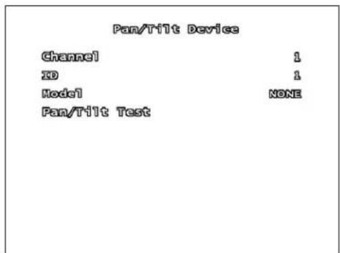
PAN/TILT DEVICE SUBMENU
NOTE: The configuration settings for this section would be provided with the documentation included with the PTZ Camera.
CHANNEL: Select the Channel where PTZ camera is connected.
ID: Assign the specific ID of the PTZ camera.
- MODEL: Select the model of PTZ camera.
PAN/TILT TEST: Test PTZ Camera.
F/W UPGRADE
The DVR supports upgrading the Firmware through a USB Memory Stick.
If a USB Memory Stick is not detected by the system, a failure message will appear:

If a USB Memory Stick is detected with valid Firmware files, the following screen will appear:
Press the PLAY Button to update the firmware, or press the STOP Button to cancel.
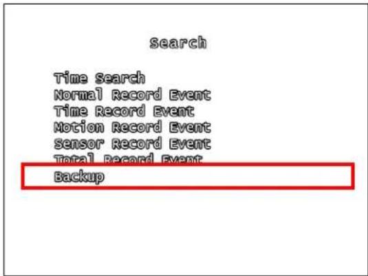
SEARCH MENU
The Search Menu contains a list of submenus to search through previously recorded video.
Use the arrows to navigate through the settings, and the arrows to change the values. Press the MENU/EXIT button to return to the previous menu.
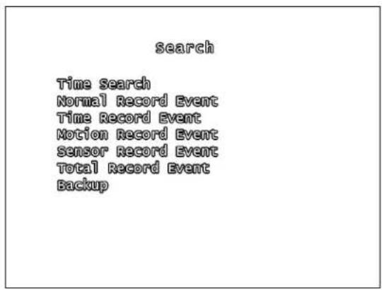
TIME SEARCH: Searches for video based on Time and Date.
NORMAL RECORD EVENT: Searches for video that was recorded manually (using the REC button).
TIME RECORD EVENT: Searches for video that was recorded on a schedule.
MOTION RECORD EVENT: Searches for video that was recorded when motion was detected.
- SENSOR RECORD EVENT: Searches for video that was recorded during a sensor event.
TOTAL RECORD EVENT: Displays all recorded video.
- BACKUP: Allows the user to back up data to a USB Memory Stick.
STATUS MENU
The Status Menu Displays the System Information. Pressing the REV key will also display the Status Window.
FACTORY DEFAULT MENU
Choosing the Factory Default option reinitializes the menu configuration in the system.
NOTE: Video data is not erased when a Factory Reset is performed.
EXIT MENU
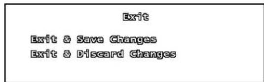
- EXIT & SAVE CHANGES: Saves all changes made, and exits the Menu.
- EXIT & DISCARD CHANGES: Exits the menu without saving any changes.
NOTE: If the menu times out and returns the user to the live viewing screen, any changes made to the Menu will not be saved.
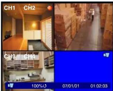
RECORDING
When a Channel is displaying a symbol, it indicates that the channel is in record mode.
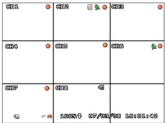
In the above example, CH1~CH7 are in record mode, and CH8 is showing a Video Loss symbol.
Additional onscreen Information includes the HDD Space, Date and Time.
NOTE: If the Date/Time is incorrect, please see the Menu settings to set the correct information.
There are several options for recording:
No Record
Time Record
Motion Record
- Sensor Record
Motion + Sensor Record
- Time + Motion Record
Recording Schedule Symbols:
White (No Recording)
Red (Continuous Recording): The DVR is constantly recording, and does not detect Motion or Sensor events.
Green (Motion Detection Recording):
Begins recording when Motion is detected, and does not record continuously or when a sensor event occurs.
Yellow (Sensor Recording): Begins
recording when a Sensor is activated, and does not record continuously or when a motion event occurs.
Green & Yellow (Motion & Sensor
Recording): Begins recording when a Sensor is activated or when Motion is detected. The DVR will not record continuously under this setting.
Red & Green (Continuous & Motion
Recording): The DVR is constantly recording.
When the cameras recognize motion, an event is written to the Event List.
Using the mouse lets the user set the schedule quickly. Set one block in the Hour or Day, and then click the corresponding top/side arrow to set the entire line to the same recording type.
SEARCH FUNCTION
There are several ways to access the Search Function:
From the Main Menu / Search Menu
- Pressing the PLAY Button
- Pressing the SEARCH Button
However, each Search menu contains different search options:
Main Menu / SEARCH Button Menu
search
Time search
Normal Record Event
Time Record Event
Notion Record Event
sensor Record Event
Total Record Event
Backup
PLAY Button Menu
Search
Normal Record Event Time Record Event Notion Record Event sensor Record Event Total Record Event
Time Search
The Time Search option allows the user to search for Video by entering the Date and Time for the desired data.
Time Search
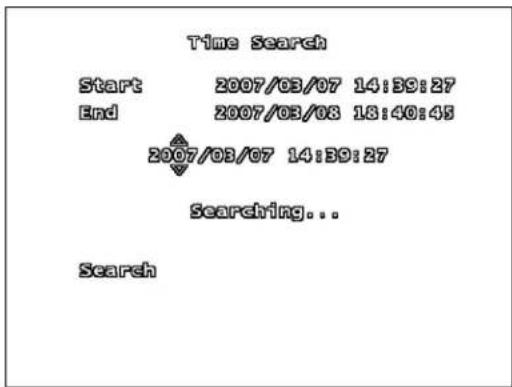
- Start: Displays the Date and Time for the first available recording.
- End: Displays the Date and Time of the last recording.
Press the Enter Button To set the Date and Time. Use the arrows to set the desired Date and Time, and press the Menu/Exit Button to accept.
Once the Date and Time are entered, navigate to the Search option, and press the Enter button. The video will start playing starting from the specified time.
Press the Stop Button to end the playback.
SEARCH TYPES
search
Time search
Normal Record Event
Time Record Event
Notion Record Event
sensor Record Event
Total Record Event
Backup
RECORD EVENT LISTS
EventList
| 0001 | 2007/03/07 | 04:39:27 | Normal Start |
| 0002 | 2007/03/07 | 08:40:45 | Motion Start |
| 0003 | 2007/03/07 | 10:39:27 | Motion Start |
| 0004 | 2007/03/07 | 13:47:45 | Sensor Start |
| 0005 | 2007/03/07 | 21:39:27 | Time Start |
| 0006 | 2007/03/03 | 08:40:45 | Motion Start |
| 0007 | 2007/03/07 | 10:39:27 | Time Start |
| 0008 | 2007/03/03 | 10:40:45 | Sensor Start |
| 0009 | 2007/03/03 | 14:40:45 | Normal Start |
Page 0001
The Record Event Lists display all Events of a specific type (as described in the Search Types section):
TIME SEARCH: Searches for video based on Time and Date.
NORMAL RECORD EVENT: Searches for video that was recorded manually (using the REC button).
TIME RECORD EVENT: Searches for video that was recorded on a schedule.
- MOTION RECORD EVENT: Searches for video that was recorded when motion was detected.
- SENSOR RECORD EVENT: Searches for video that was recorded during a sensor event.
- TOTAL RECORD EVENT: Displays all recorded video.
- BACKUP: Allows the user to back up data to a USB Memory Stick.
Event Number: The Event Number is listed on the Left of the listing. Up to 100,000 events can be displayed on 9999 pages
- Date & Time: Displays the date and time of the event
Event Type: Lists the type of event recording (Normal, Motion, Sensor or Time Recording)
- Up/Down Arrows: Use the mouse to switch between events
Page Number & Left / Right Arrows: Switch between pages.
VIDEO PLAYBACK
| CH1 | CH2 | CH3 |
| CH4 | CH5 | CH6 |
| CH7 | CH8 | 100% 07/03/03 103 16:01:42 |
The L200 Series DVR can play previously recorded video onscreen, while still recording live video images.
| BUTTON DESCRIPTION | |
| PLAY / PAUSE | Playback of previously recorded data / Pauses the data playback |
| REC Start manually recording / Stop recording | |
| FF Fast Forward the video playback. Press the FF button to change playback speed to 2x, 4x or 8x speed. | |
| REW Reverses the video playback. Press the REW button to change playback speed to 2x, 4x or 8x speed. | |
| STOP Stops the playback, and returns to live monitoring mode. | |
NOTE: A detailed Button description can be found in the Front Panel section of this manual.
The video playback can be displayed in Single (Full Screen) or QUAD. To change the onscreen display, press the CH1~CH4 buttons (L204 Series) or the CH1~CH8 buttons to change the view.
The Date and Time of the video image are displayed on the lower part of the screen. The Video Playback speed is also displayed.
BACKUP FUNCTION
There are two methods to backup video data:
- To a USB flash drive
To a Blank CD
NOTE: This DVR does not support video backup when live recording is occurring. Recording must be stopped before data backup can be performed.
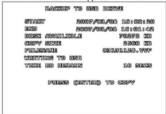
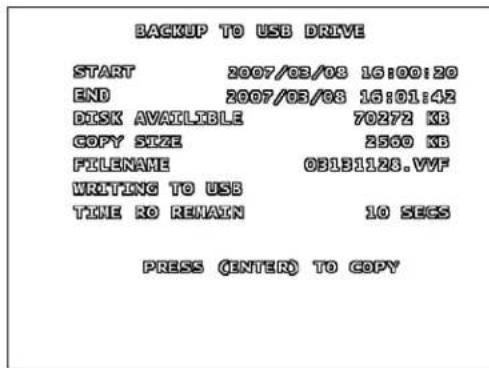
USB MEMORY STICK BACKUP
To save video to the USB Memory Stick, the start and end times for the selection must be set:
Press the buttons to set the backup starting and ending points
The Available Disk Space and copy size are shown in KB
- Press the SEARCH button to start the backup.
NOTE: It is recommended that the size of the USB Memory Stick is compared against the Copy Size before starting Backup. If the drive space is too small, the message "CAPACITY IS NOT ENOUGH" will appear.
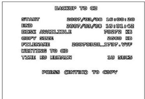
BACK-UP VIA CD-R/W* (OPTIONAL)
To save video to the CD-RW, set the start and end times for the selection:
- Press the buttons to set the backup starting and ending points
The Available Disk Space and copy size are shown in KB - Press the SEARCH or REC button to start the backup.
If the data size is larger than 600 MB, the message "DATA SIZE IS BIG TO COPY" is displayed onscreen.
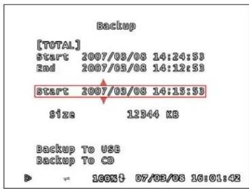
USING THE BACK-UP FUNCTION
- Start / End: Use the arrows to select the desired Start and End times for the backup.
TOTAL: Displays the date of the first and last recorded video on the DVR. - BACKUP: Indicates the desired start and end times for the data.
Size: Indicates the total size of the desired data.
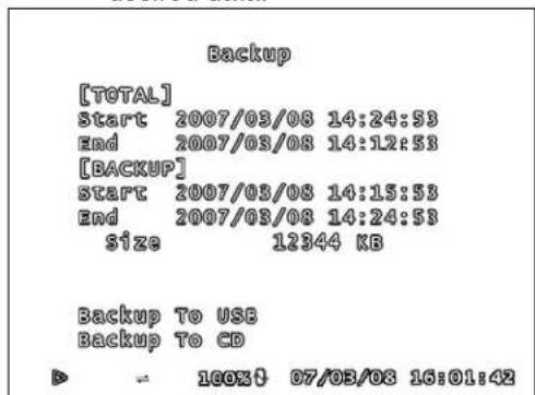
*CD/DVD-RW optional. Hardware configuration varies by model.
Use the Arrow keys and Enter Button to change the Starting and Ending Date and Time. Use the Menu button to Exit the changes.
Once the total size of the data has been displayed, use the arrows to select the Backup Type (Backup to USB or Backup to CD) and press ENTER.
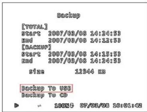
Once a backup type has been selected, the DVR will copy the information to the USB flash drive or CD.
FIRMWARE UPGRADE
The DVR supports upgrading the Firmware through a USB Memory Stick.
- Download the new firmware from http://www.lorexctv.com to the PC.
- Copy the firmware files to a USB Memory Stick.
- Insert the Memory Stick into a USB Port on the DVR.
- Navigate through the System Menu: SETUP Menu => SYSTEM Menu => F/W UPGRADE.
NOTE: If a USB Memory Stick is not detected by the system, a failure message will appear:
F/W Upgrade
USB Device Does Not Exist
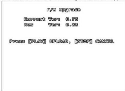
If the USB Memory Stick is detected with valid Firmware files, the following screen will appear displaying the Current Firmware Version and the New Firmware Version:
F/V Upgrade
Current Ver: 0.75
New VEP:0.85
Press [PLAY] UPGLOAD, [STOP] GANGEL
Press the PLAY Button to update the firmware, or press the STOP Button to cancel.
NOTE: If the system is actively recording, the Firmware Upgrade cannot take place. If recording is in progress, press the STOP button to end the recording before proceeding with the firmware upgrade.
The message FIMWARE UPLOADING... will appear during the upgrade process. Once the upgrade is completed, the system will reboot.
FAM Upgrade
Current Ver: 0.75
New Var:0.85
[Firware uploading...]
After the system has rebooted, the initial loading screen displays the new firmware version.
NOTE: Once the system has started the Firmware Upgrade, DO NOT remove the USB Memory Stick until after the system has rebooted and reloaded to the Live Monitoring screen.
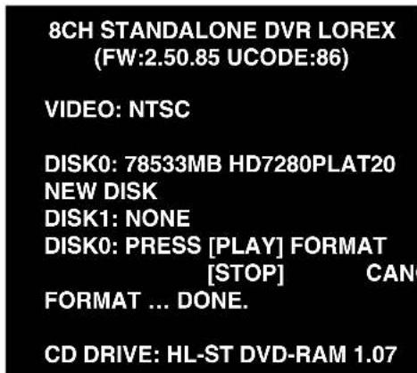
To confirm that the Firmware has been upgraded successfully, check the new version on the loading screen.
8CH STANDALONE DVR LOREX
(FW:2.50.85 UCODE:86)
VIDEO:NTSC
DISK0:78533MB HD7280PLAT20
NEW DISK
DISK1: NONE
DISK0: PRESS [PLAY] FORMAT
[STOP]
CANCEL
FORMAT...DONE.
CD DRIVE: HL-ST DVD-RAM 1.07
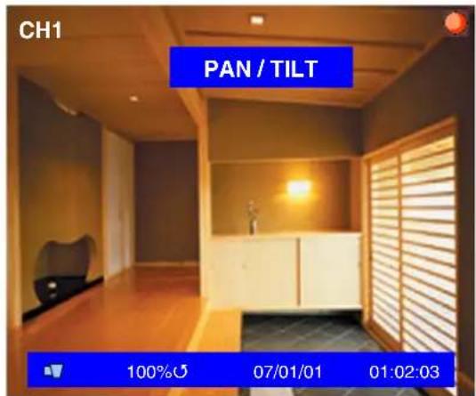
PTZ (PAN/TILT/ZOOM)
This DVR supports a PTZ Camera via the RS485 Serial Interface (see Appendix #6 for details).
Press the PTZ button in Live Monitoring mode to enter PTZ control mode. PTZ control buttons include:
| Button | Description |
| PTZ Enter / Exit PTZ mode. | |
| UP Moves the camera UP. | |
| RIGHT Moves the camera RIGHT. | |
| DOWN Moves the camera DOWN. | |
| LEFT Moves the camera LEFT. | |
| FF | ZOOM |
| REW | ZOOM |
| CH1~8 (Select PTZ camera) | Select the camera ID for PTZ control. The camera ID is the same as channel No. |
IN OUT
By default, a channel is NOT selected with the PTZ Button is pressed. Select the channel button CH1~8 that corresponds to the PTZ Camera Connection and Setup.
i.e. If the PTZ camera is connected to CH1, select the CH1 button. Press the buttons to control the camera, and press the PTZ button to exit.
Lorex Client Application
The L200 Series DVR comes with the Lorex Client application for remote monitoring, recording, DVR control or playback of video data on a PC.
The Lorex Client Application has two components:
- Player Mode: Used to view video data from a backup device such as a USB Memory Stick or CD-RW.
- Viewer Mode: Used to remotely connect to the DVR.
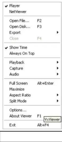
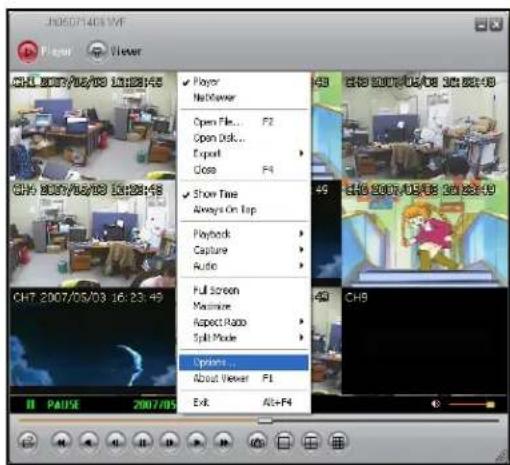
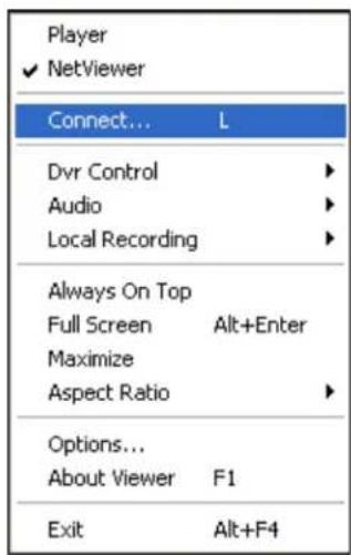
Once the program is running, a program bar will appear in the System Tray (Located next to the Start button on the bottom of the Windows screen). Right click on the Program to display a quick link menu,
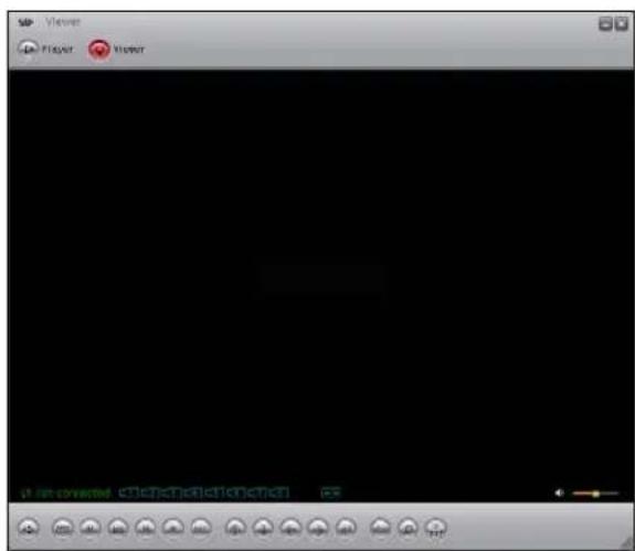
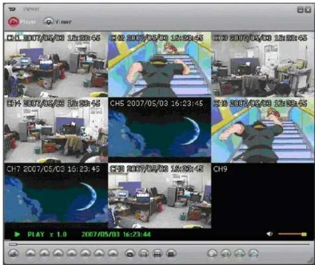
PLAYER MODE
The Player Mode is used to view video data from a backup device such as a USB Memory Stick or CDRW.
PLAYBACK METHOD
To view video data, first connect the USB memory stick to the PC or place the CD into CD/DVD Drive. Once the backup data is connected to the PC, start the Lorex Client program
Click the Player icon on the top of the Lorex Client program to switch to Player mode.

Click the icon on the lower left side of the player. Click the right mouse button to select the Open File on the player program.
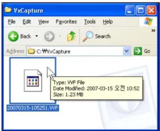
A pop-up window will appear displaying the data backup.
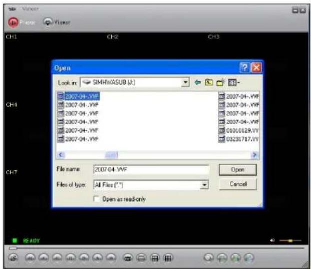
Files copied from the DVR are saved as .VVF or .NVF format. Select the desired file for playback.
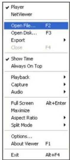
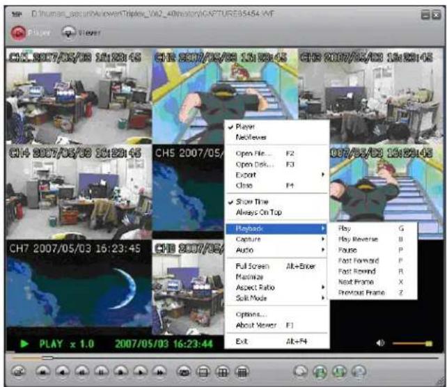
PLAYER MENU
PLAYBACK
The playback menu includes buttons for:
- Play
- Reverse
- Pause
- Fast Forward
- Fast Rewind
Next Frame
Previous Frame - Speed Normal
- Speed Up
- Speed Down
These function buttons are arranged along the bottom of player program.
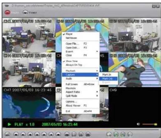
Capture
The Capture function can be used to save parts of the video to the local hard drive.
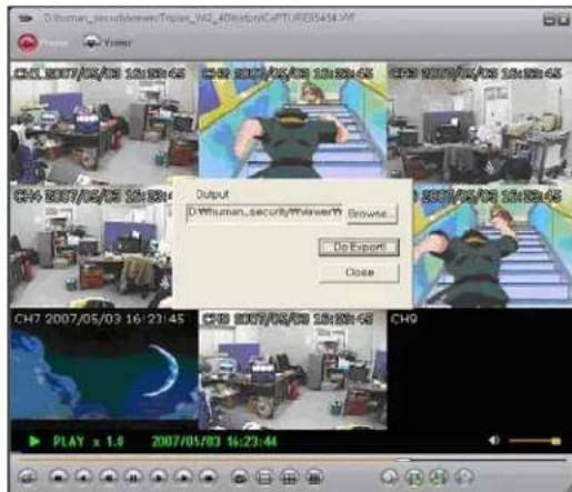
Click the Export link to save the selected video to a *.VVF file. Click the Mark In link at the starting point and Mark Out at the end point.
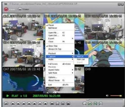
- Click the Browse button to assign a Save location.
- Click the Do Export button to save the video to the local hard drive.
- Click the Close button to exit the window.
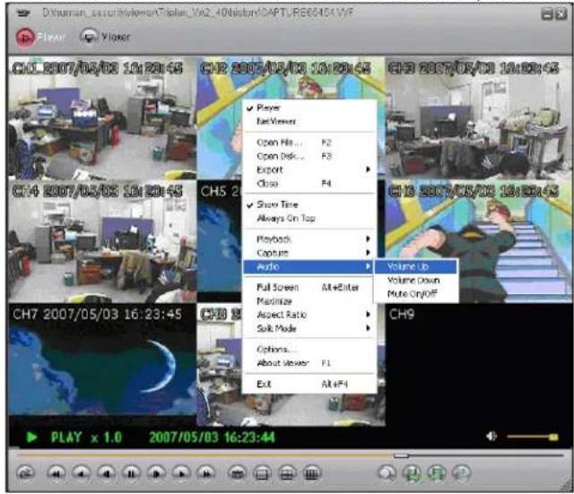
AUDIO FUNCTION
The Audio Function controls the Audio Volume, and turns the MUTE ON/OFF.
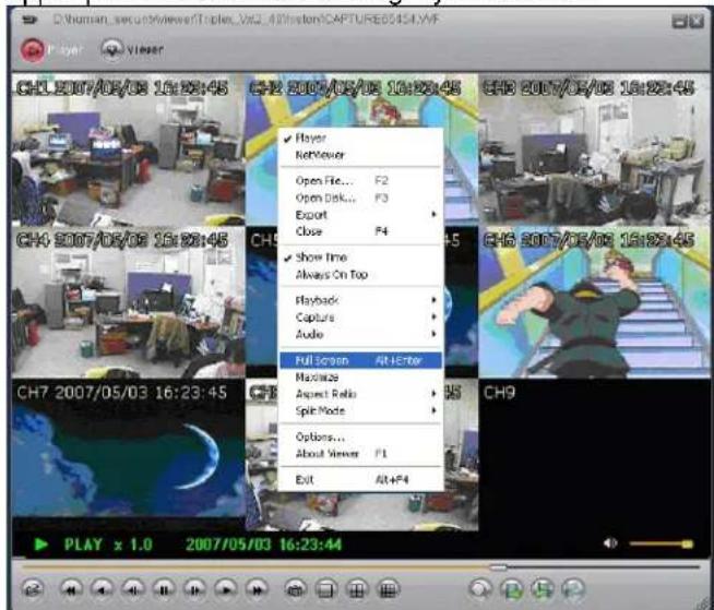
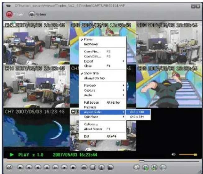
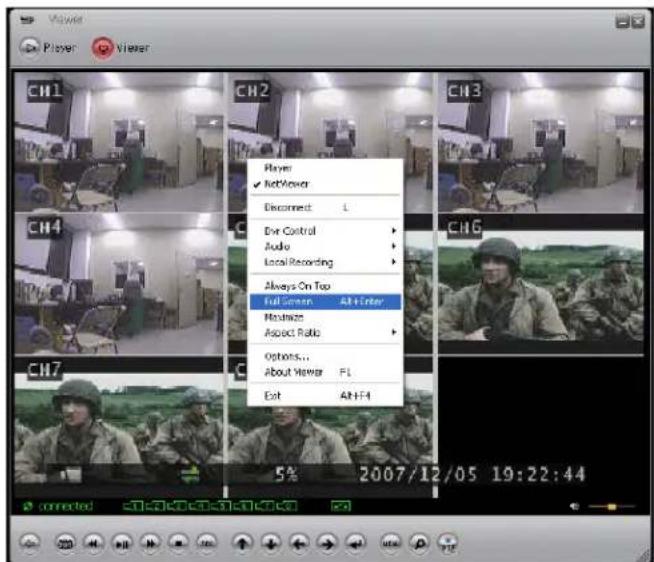
Full Screen
Select Full Screen to view a single camera in Full Screen mode, or Press Alt+Enter. Double click the upper part of the window to magnify the screen.
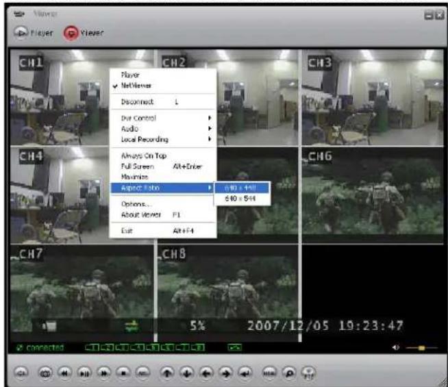
Aspect Ratio
The screen size can be set to 640x448 or 640x544.
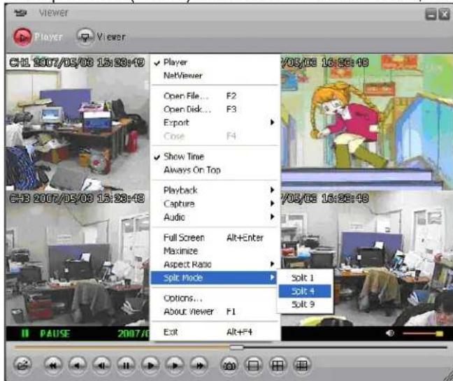
Split Mode
The Split mode (QUAD) can be set to 1ch full screen, 4ch Quad screen, 9ch split screen.
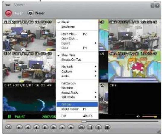
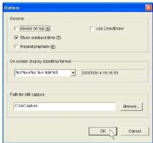
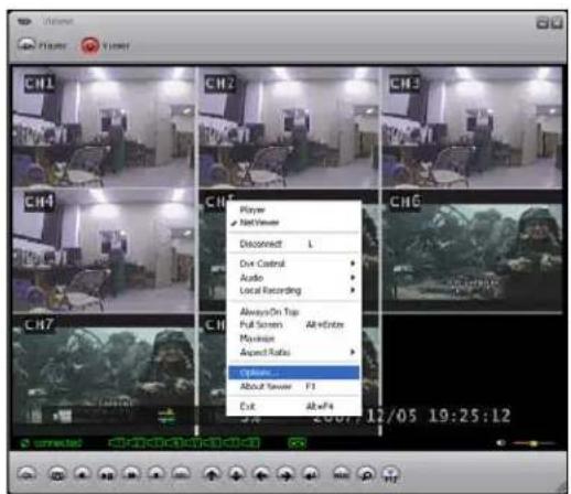
Option Menu
The Option Menu includes settings for:
- Playback
- Date and time format
- Save Folder
General Options
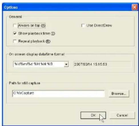
Always on top: Highest level on window
Use DirectDraw: Use the applied program interface (API) included in Direct X.
- Show playback time: Set to show the playback time on the screen.
Repeat playback: Repeat Playback
- On screen display date/time format: Set the date/time format on the screen.
- Path for still capture: Set the path for still capture.
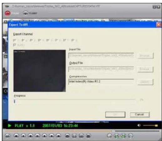
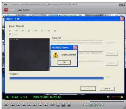
Export
Save video data backup as an AVI format on the computer.
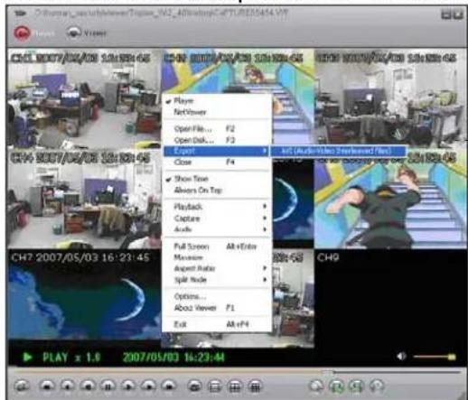
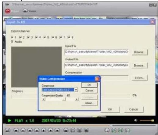
- Select the video data to backup (select Input File).
- Select a location and a name for the saved file (select Output File).
- Select the Compression type on the Compression Select menu, and click OK
- Click the Export Channel OK button, and the program will save the file. The Image file (AVI) is saved per channel.
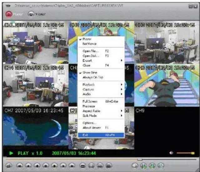
Close Viewer
To close the Viewer, click the EXIT button, or click the X button on the top-right side of program to close.
BUTTON FUNCTION
You can click the buttons shown below on the program to perform the matching function, or use the shortcut keys listed.

| ICON | SHORTENING KEY | FUNCTION |
| F2 Open and play video file. | ||
| R | Rewind. | |
| B | Play Reverse. | |
| Z Go one frame | backward and Pause. | |
| P | Pause. | |
| X Go one frame | forward and PAUSE. | |
| G | Playback. | |
| F | Fast Forward. | |
| - | When you click this button, it will take a single frame of video image while playback and then it will automatically save the image. (BMP format) into the local PC directory (Initial folder setup: “C:\VxCapture”) | |
| - View in 1-channel full screen mode. | ||
| - View in 4-channel screen mode. | ||
| - View in 8-channel screen mode. | ||
| - Search symbol for HDD connection. | ||
| - | Mark In | |
| - | Mark Out | |
| - | Export | |
| Adjust volume or enable speaker sound ON/OFF. | ||
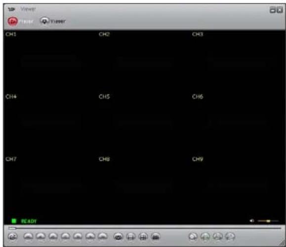
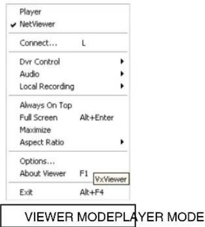
VIEWER MODE
The DVR can be viewed remotely using the Viewer portion of the application.
CONNECTING WITH VIEWER
To monitor the DVR through the VIEWER program, check that a network connection between the DVR and PC can be established. The Viewer program can be used to connect to the DVR on the Local Area Network (LAN), or remotely through the Internet (WAN).
Launch the Lorex Client program, and Click the Viewer icon on the top of client program.

Click on the button on the bottom-left side of VIEWER program (or press the L key). Click the right mouse button and select the Connect option on the menu.
Once the Login Box appears, enter the IP Address, Port and Password. Press the LOGIN Button to connect to the DVR.
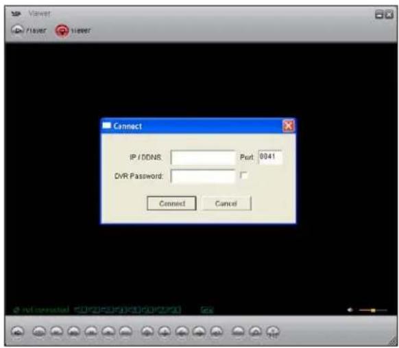
The following information is needed for connection to the DVR:
IP/DDNS: Enter the internal or external IP address or DDNS ID.
- Port: Enter the port for the DVR.
- DVR Password: Enter the password for the DVR. If the box is checked, the connection information will be saved for the next time the program is launched.
CONNECTING ON THE LAN:
To connect to the DVR on the LAN, press the REW button on the DVR to get the local IP address (i.e. 192.168.0.104). Enter the following information on the connection window:
IP Address: The IP of the DVR (i.e. 192.168.0.104)
- Port: Enter 8841 (default)
- Password: Enter 111111 (default password. If the password has been changed on the DVR, use the changed password).
CONNECTING ON THE WAN (REMOITERLY OVER THE INTERNET):
NOTE: Before starting the Viewer Mode to remotely connect to the DVR, configure the DDNS service (as shown earlier in the Networking section of this manual), and configure the DVR by navigating through the System Menu on the DVR:
- SYSTEM -> NETWORK -> NAME SERVER
Set the ENABLE option to ON. Make sure to record the IP ADDRESS, PORT and DVR NAME (DVR ID) listed on the DDNS Settings. If the external IP address is needed, check your router settings, or visit http://www.showmyip.com
If the DDNS of the DVR does match the settings in the DDNS configuration portion of the VIEWER, the connection will fail. If the DDNS name does not work, then use the external IP ADDRESS for your network connection (i.e. 74.134.55.22) PORT (8841) and DVR NAME (any character or number) can be used instead. Please see the network section of this manual for information on locating the external IP address.
Enter the following information on the connection window:
- IP Address: The DDNS Address (only the first part of the address is needed, so use 'myurl' from http://myurl.strategicvista.net) -or- the external IP address of the DVR (i.e. 74.134.55.22)
- Port: Enter 8841 (default)
- Password: Enter 111111 (default password. If the password has been changed on the DVR, use the changed password).
VIEWER MENU
DVR Control
The DVR can be controlled through the Viewer portion of the Lorex Client application.
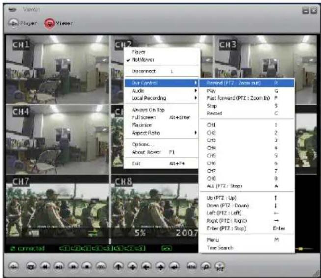
The DVR control panel has the following buttons located on the bottom panel:
- Pause
- Rewind
Play
Fast Forward - Stop
Record
All - Channel 1~Channel 8
- Up, Down, Left, Right
- Enter
- Menu
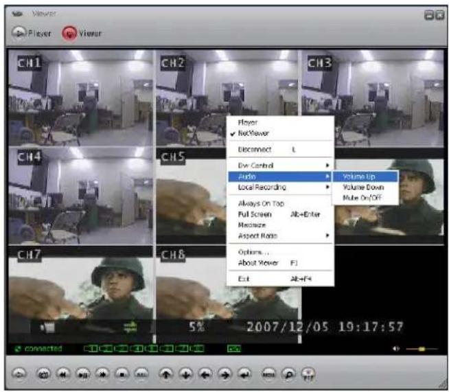
Audio
The Audio option controls the Volume, and setting the mute to ON or OFF during playback.
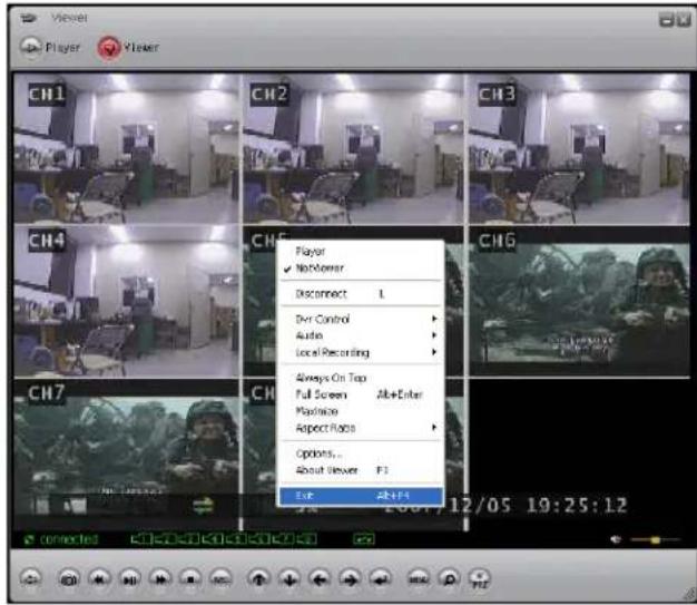
Local Recording
The live video stream can be saved to the connected PC using the viewer program. Click the Local Recording -> Start Local recording menu to begin saving the data. Click the Stop Local Recording menu to end the data save to the local PC.
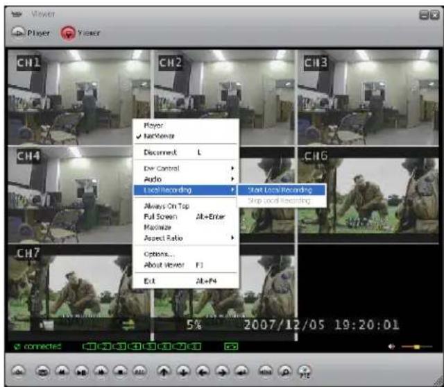
Video image files will be saved to the directory set in Options (the Default Directory: C:\VxCapture). To playback the file, switch the mode from [VIEWER] to [PLAYER].
Full Screen
To change the screen to Full Screen mode, select the FULL SCREEN option or press ALT+F4. Double click on the upper port of program to maximize the screen.
Aspect Ratio
The screen size can be set to 640 X 448 or 640 X 544.
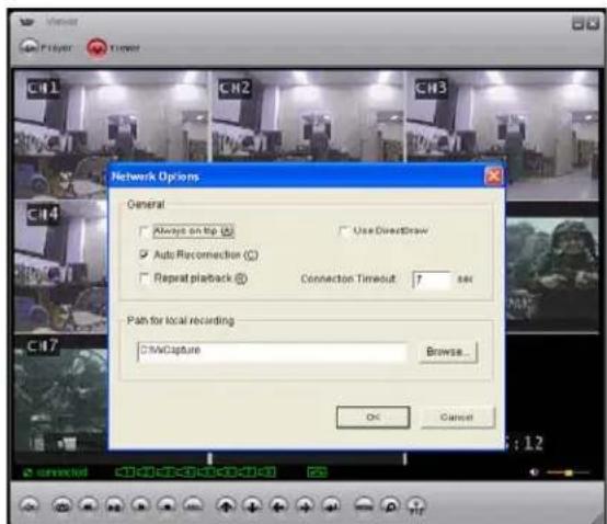
OPTION FUNCTION
The option menu includes:
- Repeat playback
- Connection Attempts
- Auto Reconnection
The save folder for video
GENERAL OPTIONS
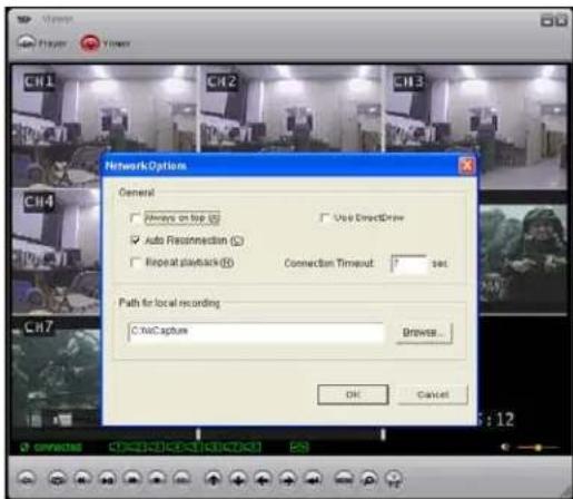
Always on top: Places the window at the top of the screen.
- Use DirectDraw: Use the applied program interface (API) included with Direct X.
- Auto Reconnection: Attempts to reconnect with the DVR when the connection fails.
- Repeat playback: Repeats the playback.
- Connection Timeout: Set a time for connection timeout.
- Path for recall recording: Set the directory for saving video to the local PC.
Close Viewer
To close the Viewer, click the EXIT button, or click the X button on the top-right side of program to close.
BUTTON FUNCTION
You can click the buttons shown below on the program to perform the matching function, or use the shortcut keys listed.

| ICON | SHORTENING KEY | FUNCTION |
| L | Connect /Disconnect DVR. | |
| - Save present screen | ||
| G | Play/Pause. | |
| R | Rewind. | |
| F | Fast Forward. | |
| S | Stop. | |
| C | Record. | |
| ↑↓←→ | ··· ··· | Up, Down, Left, Right. |
| Enter key Enter | / Select | |
| MENU | M Menu / Exit | |
| - Time Search. | ||
| PTZ | - | PTZ |
DVR Specifications - Appendix #1
| Feature L204 series | L208 series | ||
| Operating system Real-time (RTOS) | Real-time (RTOS) | ||
| Video Input 4 Channel (BNC) 8 Channel (BNC) | Channel (BNC) | ||
| Video Output | 2 Channel (2-composite/1-VGA) | 3 Channel (2-composite/1-VGA) | |
| Video Input Standard NTSC / PAL NTSC / PAL | |||
| Monitoring Resolution | NTSC 720*480 Pixels 720*480 Pixels | ||
| PAL 720*576 Pixels 720*576 Pixels | |||
| Recording Resolution | NTSC 640*224 Pixels 640*224 Pixels | ||
| PAL 640*272 Pixels 640*272 Pixels | |||
| Display Frame rate | NTSC 120fps (Real time) 240 fps (Real time) | ||
| PAL 100fps (Real time) 200 fps (Real time) | |||
| Recording Frame rate | NTSC Max. 60 fps(each 15fps) Max. 60 fps(each 7.5fps) | ||
| PAL | Max. 50 fps | Max. 50 fps | |
| Display Mode | EACH/QUAD | EACH/QUAD/EIGHT | |
| Recording Compression Format | Motion JPEG | Motion JPEG | |
| Transmission (network)Compression Format | MPEG4 | MPEG4 | |
| Image Size(Each Channel) | Low 12 Kbytes/frame12 Kbytes/frame | ||
| Normal | 15 Kbytes/frame | 15 Kbytes/frame | |
| High | 20 Kbytes/frame | 20 Kbytes/frame | |
DVR Specifications - Appendix #1
| Recording Mode | Continuous / Motion/Schedule/sensor | Continuous / Motion/Schedule/sensor |
| HDD Capacity | HDD * 2 (Max 500GB ea = 1TB) | HDD * 2 (Max 500GB ea = 1TB) |
| Motion detection ON / OFF Control | ON / OFF Control | |
| Audio 1 Ch. 1 Ch. | ||
| LAN Yes (DHCP, Static IP, PPPoE) | Yes (DHCP, Static IP) | |
| PTZ Yes (RS485) Yes (RS485) | ||
| Sensor / Alarm 4 Ch Input / 1Ch Output 4 Ch Input / 1Ch Output | ||
| CD-RW/DVD-RW Yes (optional) Yes (optional) | ||
| VGA Yes (1024x768) Yes (1024x768) | ||
| Mouse support | Yes (PS/2) | Yes (PS/2) |
| Camera Control | Color, Tint, Brightness | Color, Tint, Brightness |
| USB backup and firmware upgrade | Yes (USB 2.0) | Yes (USB 2.0) |
Full Connectivity Diagram - Appendix #2
The following diagram outlines a general set of connections available with the DVR.
Hard Drive Replacement - Appendix #3
The DVR comes with a pre-installed Hard Drive; however the unit will work with a replacement single IDE Hard Drive (up to 500GB). A maximum of two (2) Hard Drives can be installed into the DVR; however the CD-RW must first be disconnected. *
The Hard Drive storage capacity and model name are shown on the loading screen when the DVR system loads. If the DVR does not recognize the Hard Drive, the system will not boot. If a new Hard Drive is used in the DVR, the system will prompt to format the drive. Any drive formatted by the DVR will not be recognized by a PC, and the data cannot be accessed.
NOTE: Make sure that the DVR is OFF and the power cable has been disconnected before changing the Hard Drive.
Removing the Back Cover and Installed Drive
- Remove the screws from the DVR Cover. Remove the cover panel.
- Remove all cables from the previously installed drive.
- Remove the screws holding the drive to the case.
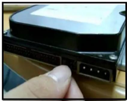
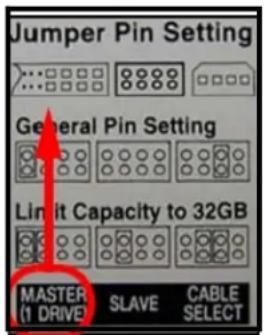
Setting the New Drive to Master
- Refer to the General Jumper Pin Setting on HDD Surface (generally located on a sticker on the top of the drive).
If using one (1) Hard Drive, set the Jumper Pin Set to Master (1 Drive). - If two (2) Hard Drives are installed into the DVR, set one drive to Master, and one drive to Slave. When using two Hard Drives, remember to first disconnect the CD-RW Drive.
NOTE: Use an IDE Hard Drive.
*CD/DVD-RW optional. Hardware configuration varies by model.
Hard Drive Replacement (cont'd.)
Installing the New Drive
- Place the new drive in the case, and reattach the holding screws.
- Reconnect the cables in the same way as connected to the previous drive.
o Reconnect the IDE Cable. Confirm that the cable is securely connected within the DVR and to the Hard Drive.
o Reconnect the Hard Drive power cable. Confirm the cable is securely connected to the Hard Drive.
- Replace the drive cover on the top of the DVR, and reattach with the screws.
New Hard Drive Format
The New Hard Drive MUST be formatted.
If a new HARD DRIVE is detected, the system will prompt you to FORMAT the drive. If you do not choose to format the HARD DRIVE, the drive will not be detected by the system.
If you choose to FORMAT a drive in this way, the drive will no longer be readable by a regular PC.
Press the PLAY button to format the drive, or pres the STOP button to cancel the format.
8CH STANDALONE DVR LOREX (FW:2.50.85 UCODE:86)
VIDEO: NTSC
DISK0: 78533MB HD7280PLAT20 NEW DISK
DISK1: NONE
DISK0: PRESS [PLAY] FORMAT [STOP] CAN
FORMAT ... DONE.
CD DRIVE: HL-ST DVD-RAM 1.07
NOTE: If using multiple Hard Drives, the format will erase data on BOTH drives. When using two (2) Hard Drives, it is recommended to back up any data on the existing drive before installing the second one.
RTC (Real Time Clock) Chip
RTC (REAL TIME CLOCK) CHIP contains the system information and menu settings. If the battery for RTC is discharged, the system will reset to default (factory) settings.
Troubleshooting - Appendix #4
When a malfunction occurs, it may not be serious and can be corrected easily. The following describes the most common problems and solutions. Please refer to the following before calling Lorex Technical Support:
Problem:
DVR Unit is not receiving power, or is not powering up
Check:
- Confirm that all cables are connected correctly.
- Confirm that the power adapter is securely connected to the back of the unit.
-
Confirm that there is power at the outlet by:
-
Connecting the power cable to another outlet
Testing the outlet with another plugged device (such as an electric calculator or phone charger) -
If the unit is connected through a power bar or surge protector, try bypassing the bar and connecting the power directly to the wall outlet.
- Confirm that the unit is powered on (LED indicators on the front should be ON).
Problem:
The DVR is not responding when any of the buttons are pushed.
Check:
- Turn the master power OFF by removing the POWER CABLE. The LED indicators should be OFF.
- Wait for 1 minute - Reconnect the POWER CABLE.
- The unit will make an audible alert when powered back on
Problem:
The image on the DVR is too dark or too bright
Check:
- Adjust the CONTRAST and BRIGHTNESS of the unit (Refer to the Menu section)
Problem:
The image on the DVR does appear, but does not have sound.
Check:
- Check the VOLUME
- Check the CAMERA connection to the DVR (DIN CONNECTION ONLY).
- Confirm that the Camera has sound capabilities (Refer to the manual for the camera model for further information on the Camera functionality)
Troubleshooting (cont'd.)
Problem:
The picture on the DVR is poor, shrinks or flickers
Check:
- Check the camera video cable and connections
- Disconnect and reconnect the cable at the DVR and at the Camera
- Clean the camera lens
- Adjust the CONTRAST and BRIGHTNESS settings in the Menu
- Check that the Camera is not in direct sunlight
Problem:
There is no picture appearing on a Channel / Camera is not displaying
Check:
- Check the camera video cable and connections
- Disconnect and reconnect the cable at the DVR and at the Camera
- Try moving the camera to another channel or use another cable
Appendix #5 - Network Connectivity Overview
The DVR can be remotely controlled using your existing network and the provided software.
- Connect the DVR to the Router using an Ethernet Cable. Power the DVR on.
NOTE: The DVR must be connected to the router prior to powering on the system. This allows the DVR to communicate on your network - Find the IP address of your DVR through the Menu System on the unit. See the Menu section of this manual for additional System Settings.
- Set up a web account at http://lorexdns.net
- Enable PORT FORWARDING on your Router.
- Run the EXE file from the Software CD provided with your system. See the Software Section of this manual for details on Software setup.
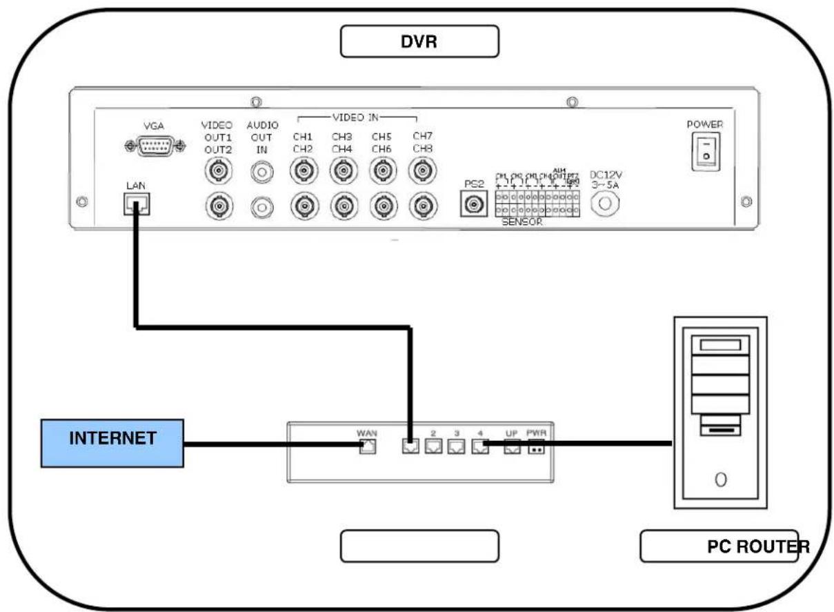
IP & MAC Address (Step #2)
The IP & MAC Addresses are necessary for DDNS Setup (for remote access to the DVR).
To Locate the System information, Press the REV Button on the Front Panel or Remote Control while viewing the Cameras. The System Info window will be displayed.
-OR
-
Press the Menu Button on the Front Panel or Remote Control to access the Setup Menu. Select the System Menu option and press the Enter button.
-
Select the Status option and press Enter.
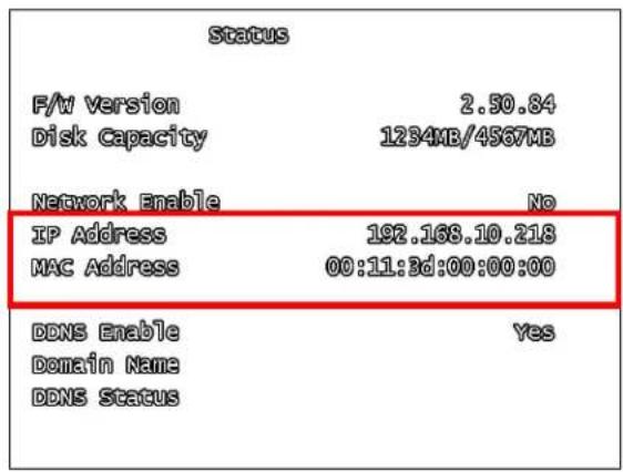
Finding Your External IP Address
You will need to have your External IP address to set up your DDNS account. One of the fastest ways to find this information is to use a 3rd Party website such as http://www.showmyip.com
Your IP address can also be found within your Router settings. Refer to your router user guide for further details.
Setting Up Your DDNS Account (Step #3)
Lorex offers a free DDNS service for use with your System. A DDNS account allows you to set up a web site address that points back to your Local Network. The following outlines how to set up your free DNS account.
- Navigate to http://lorexdns.net
- Select the Create Account option from the list on the left side of the screen.
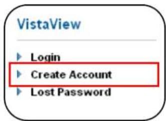
Setting Up Your DDNS Account (cont'd.)
- Complete the Account Information fields with your personal information
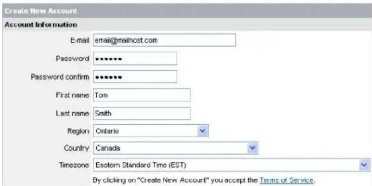
-
Complete the System Information fields:
-
Product License: Select your product model from the Product License drop down menu
- : Locate the MAC address of your (recorded while loading the System) - URL Request: Choose a URL for your DDNS connection (i.e. your name, your company or business name, or anything of your choice.)
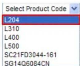
Once the information has been entered, click on the Create New Account link.
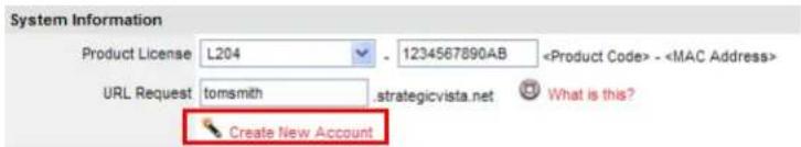
- Your Account information will be sent to you at the E-mail Address you used in Step 3.
Service Provider: dns1.strategicvista.net
User Name: tomsmith1
Domain Name: tomsmith
Password: (your password)
You will need this information for remote access to your System. Record YOUR information below:
User Name:
*Domain Name:
Password:
- Only the first part of the Domain Name is required for setup on the System. If the full Domain sent is tomsmith.strategicvista.net, the unit only requires that only tomsmith be entered.
Router Port Forwarding (Step #4)
You will need to enable port forwarding on your Router to allow for external communications with your Observation System for ports:
- PORT 8841
Computers, DVRs, and other devices inside your network can only communicate directly with each other within the internal network. Computers and systems outside your network cannot directly communicate with these devices. When a system on the internal network needs to send or receive information from a system outside the network (i.e. from the Internet), the information is sent to the Router.
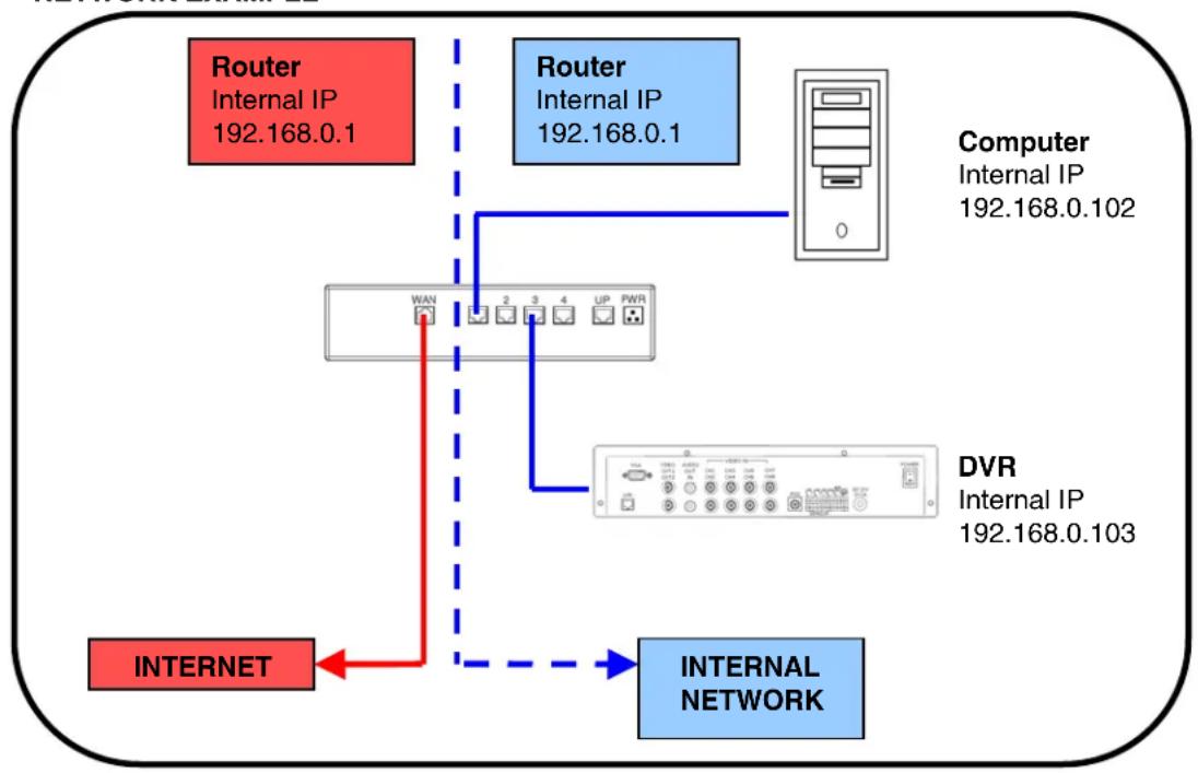
NETWORK EXAMPLE
When a computer on the Internet needs to send data to your internal network, it sends this data to the external IP address of the Router. The Router then needs to decide where this data is to be sent to. This is where setting up Port Forwarding becomes important.
Port Forwarding tells the router which device on the internal network to send the data to. When you set up port forwarding on your Router, it takes the data from the external IP address:port number and sends that data to an internal IP address:port number (i.e. Router External IP 216.13.154.34:6100 to DVR Internal IP 192.168.0.103:8841).
The instructions found online in the Router Configuration Guides will assist you in the port forwarding configurations for a selection of different router models. Visit our Consumer Guides Support website at http://www.lorexctv.com/support for more details
DDNS Setup on the DVR (Step #5)
Once the DDNS settings have been configured online, the information must be entered on the DVR to allow for remote connection via the Software:
- Access the Setup screen by pressing the MENU button on the front of the DVR. Navigate to the SYSTEM option, and press the ENTER button to access the System Setup.
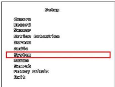
- Navigate to the NETWORK option, and press the Enter button to access the Network settings. Select the DDNS option, and press the ENTER button to enter the DDNS SETUP.
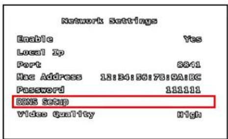
-
Set the DDNS Enable to YES. Enter the information received in email using the Virtual Keyboard:
-
DDNS ID
- DDNS Password
- Domain Name
Select OK to save the settings.
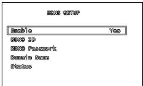
- Select the Status option to check the connection. A SUCCESS message will appear if the DVR successfully connects the DDNS Server on the Internet.
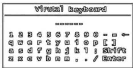

Appendix #6 - PTZ Control
One PTZ Camera (not included with this system) can be connected to the PTZ Control Block on the back panel of the DVR, and are enabled through the Menu system. Additional PTZ Cameras are available at http://www.lorexctv.com
Installing a PTZ (RS-485 Type) PTZ Camera:
- Connect the Transmit Cable to the 485+ port on the PTZ Control Block.
- Connect the Receive Cable to the 485- port on the PTZ Control Block.
- Connect the Camera to BNC Channel 1.
- Configure PTZ Menu options.
The PTZ Camera Settings will depend on the Type of Camera - refer to the specific Camera Manual for your brand and model of PTZ Camera.
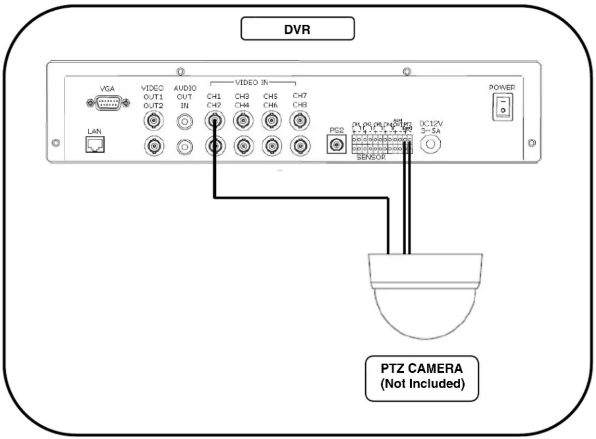
Appendix #7 - Connecting Motion / Alarm Device
Motion detection and Alarm controls are enabled through the Menu system on the DVR. Additional motion sensor devices can be connected to the system (Motion Sensors, Door/Window Sensors).
A motion detection or sensor unit can be used to send a signal to the DVR to begin camera viewing and recording on the matching Video Channel (when enabled in the Menu)
- Example: A Window sensor unit has been installed on Alarm Block port #4. When this sensor is activated, the camera on CH4 will become active (if enabled in the MENU on the DVR)
Installing a Sensor
- Connect the GROUND Cable to the desired Channel number - port on the DVR.
- Connect the SIGNAL Cable to the desired Channel number + port on the DVR.
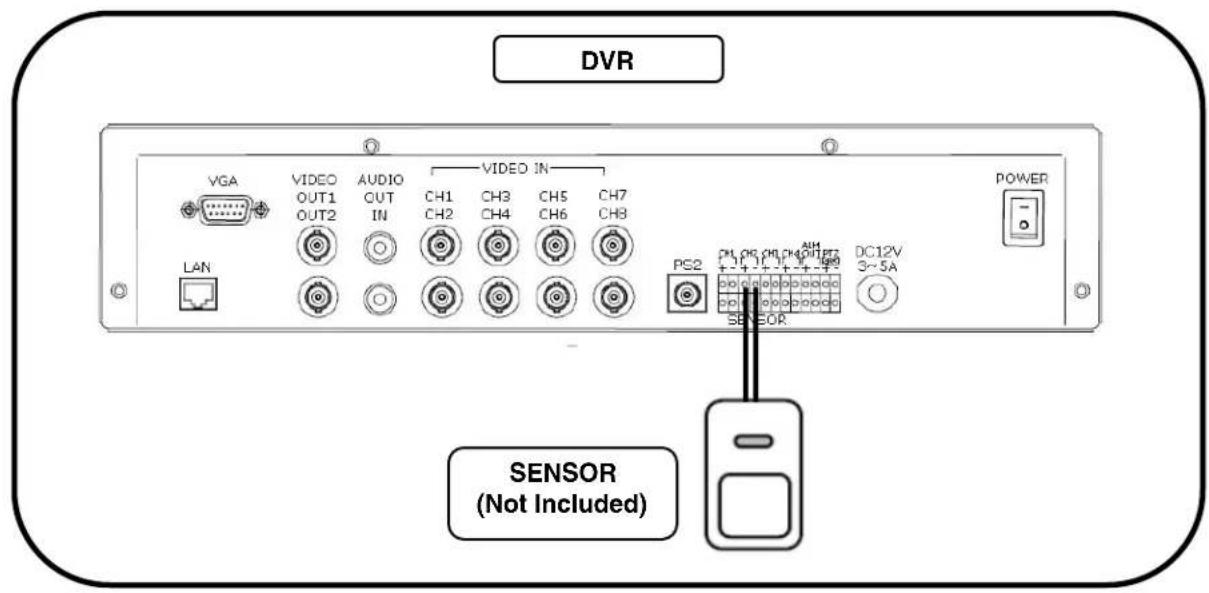
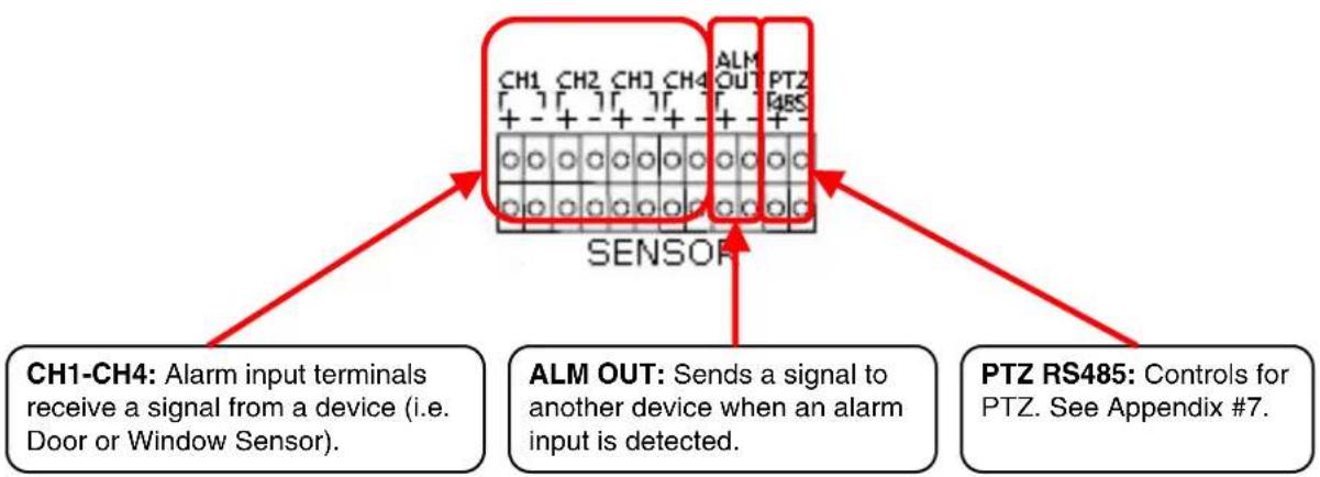
Appendix #8 - Initial Setup Menu Values
| SETUP | FACTORY | |||
| CAMERA | CHANNEL | 1 | ||
| DISPLAY | ON | |||
| BRIGHTNESS,CONTRAST,HUE,SATURATION | ----|---- | |||
| RECORD | RECORD SPEED 7 (4CH DVR 15FRAME) | |||
| RECORD QUALITY NORMAL | ||||
| EVENT REC DURATION 10 | ||||
| RECORD SCHEDULE - | ||||
| RECORD SCHEDULE ENABLE YES | ||||
| SENSOR | ALARM DURATION OFF | |||
| SENSOR1/2/3/4 | DISABLE | |||
| MOTION DETECTION | CHANNEL | 1 | ||
| SENSITIVITY | OFF | |||
| ALARM DURATION OFF | ||||
| MOTION AREA - | ||||
| SCREEN | BORDER | ON | ||
| VIDEO ADJUSTMENT - | ||||
| SEQUENCE INTERVAL 4 SEC | ||||
| AUDIO | RECORD | ON | ||
| MUTE | OFF | |||
| INPUT VOLUME ----|---- | ||||
| OUTPUT VOLUME ----|---- | ||||
| SYSTEM | DISK SETUP | OVERWRITE ENABLED YES | HARD | |
| FORMAT HDD - | ||||
| PASSWORD CHANGE | 111111 | |||
| PASSWORD ENABLE | NO | |||
| TIME SET | TIME ZONE | (GMT-05:00)[Eastern Time (US & CANADA)] | ||
| TIME SET | - | |||
| SYNC. FROM NTP SERVER | NO | |||
| NTP SERVER IP | 203.117.180.36 | |||
| SYSTEM EVENT LIST | - | |||
| NETWORK | ENABLE | NO | ||
| LOCAL IP | IP TYPE | [STATIC] | ||
| IP ADDRESS | 192.168.10.218 | |||
| GATEWAY | 192.168.10.1 | |||
| NET MASK | 255.255.255.0 | |||
| - | ||||
| - | ||||
| PORT | 8841 | |||
| MAC ADDRESS | 00:11:3D:XX:XX:XX | |||
| PASSWORD | 111111 | |||
| DDNS | ENABLE | NO | ||
| SETUP | DDNS ID - | |||
| DDNS PASSWORD | - | |||
| DOMAIN NAME | - | |||
| STATUS | - | |||
| VIDEO QUALITY HIGH | ||||
| RS485 | BAUDRATE | 115200 | ||
| DATA BIT 8 | ||||
| PARITY BIT NONE | ||||
| STOP BIT 1 | ||||
| PANTILT DEVICE | CHANNEL | 1 | ||
| ID | 1 | |||
| MODEL | NONE | |||
| PANTILT TEST - | ||||
| F/W UPGRADE | - | |||
| SEARCH | - | |||
| STATUS | - | |||
| FACTORY DEFAULT | - | |||
| EXIT | EXIT&SAVE CHANGES | - | ||
| EXIT&DISCARD CHANGES | ||||
Appendix #9 - HDD Usage Table
The following table is provided as an approximation of Hard Drive usage. Variables in image quality and frame rates may alter the hard drive usage.
HDD Usage Table
| Quality | Size Per Frame(KB) | Frame Rate | Time | |||
| 1Sec | 1Min | 1Hour | 1Day | |||
| High | 20 | 60 | 1200 | 72000 | 4320000 | |
| 30 600 36000 2160000 | 51840000 | |||||
| 15 | 300 | 18000 | 10800000 | |||
| 5 100 600 00 360000 8640000 | ||||||
| Normal | 15 | 60 | 900 | 54000 | 32400000 | |
| 30 450 27000 1620000 | 38880000 | |||||
| 15 | 225 | 13500 | 8100000 | |||
| 5 | 75 | 4500 270000 | 6480000 | |||
| Low | 12 | 60 | 720 | 43200 | 25920000 | |
| 30 360 21600 1296000 | 31104000 | |||||
| 15 | 180 | 10800 | 6480000 | |||
| 5 | 60 | 3600 216000 | 5184000 | |||
| Quality | Size Per Frame(KB) | HDD | ||||||||
| 80 GB | 160 GB | 250 GB | 320 GB | 500 GB | ||||||
| High | 20 | 0 Day | 1 Day | 2 Day | 3 Day | 4 Day | ||||
| 1 Day | 3 Day | 4 Day | 6 Day | 9 Day | ||||||
| 3 Day | 6 Day | 9 Day | 12 Day | 19 Day | ||||||
| 9 Day | 18 Day | 28 Day | 37 Day | 57 Day | ||||||
| Normal | 15 | 1 Day | 2 Day | 3 Day | 4 Day | 6 Day | ||||
| 2 Day | 4 Day | 6 Day | 8 Day | 12 Day | ||||||
| 4 Day | 8 Day | 12 Day | 16 Day | 25 Day | ||||||
| 12 Day | 24 Day | 38 Day | 49 Day | 77 Day | ||||||
| Low | 12 | 1 Day | 2 Day | 4 Day | 5 Day | 8 Day | ||||
| 2 Day | 5 Day | 8 Day | 10 Day | 16 Day | ||||||
| 5 Day | 10 Day | 16 Day | 20 Day | 32 Day | ||||||
| 15 Day | 30 Day | 48 Day | 61 Day | 96 Day | ||||||
VIDÉO ENREGISTREUR DES SURVEILLANCE NUMÉRIQUE
AVEC DÉTECTION DE MOUVEMENT ET ENREGISTREMENT SONORE
Guide d'instruction
The lightning flash with arrowhead symbol, within an equilateral triangle, is intended to alert the user to the presence of uninsulated "dangerous voltage" within the products 'enclosure that may be of sufficient magnitude to constitute a risk of electric shock

The exclamation point within an equilateral triangle is intended to alert the user to the presence of important operating and maintenance (servicing) instructions in the literature accompanying the appliance.
WARNING: TO PREVENT FIRE OR SHOCK HAZARD, DO NOT EXPOSE THIS UNIT TO RAIN OR MOISTURE.
CAUTION: TO PREVENT ELECTRIC SHOCK, MATCH WIDE BLADE OF THE PLUG TO THE WIDE SLOT AND FULLY INSERT.
DISK0: 78533MB HD7280PLAT20
READ REC INFO ... DONE
DISK 1: NONE
CD DRIVE: HL-ST DVD-RAM 1.07
[STOP] TO STOP
CH1 CH2

8CH STANDALONE DVR LOREX (FW:2.50.85 UCODE:86)
VIDEO: NTSC
DISK0: 78533MB HD7280PLAT20 NEW DISK
DISK1:NONE
DISK0: PRESS [PLAY] FORMAT [STOP] CANTI
FORMAT ... DONE.
CD DRIVE: HL-ST DVD-RAM 1.07
Time search
Normal Record Event
Time Record Event
Notion Record Event
Sensor Record Event
Total Record Event
Backup
| status | |
| F/w version | 2.50.84 |
| disk capacity | 1234MB/4567MB |
| Network Enable | No |
| IP Address | 192.168.10.218 |
| MAC Address | 00:11:3d:00:00:00 |
| DNS Enable | Yes |
| Domain Name | |
| DNS status | |
MENU DE DÉFAUT D'USINE
| Exit |
| Exit & Save Changes |
| Exit & Discard Changes |
Time search
Normal Record Event
Time Record Event
Notion Record Event
sensor Record Event
Total Record Event
Backup
Menu de bouton de PLAY
search
Normal Record Event
Time Record Event
Notion Record Event
Sensor Record Event
Total Record Event
Recherche Horaire
Time search
Normal Record Event
Time Record Event
Notion Record Event
sensor Record Event
Total Record Event
Backup
DISK0: 78533MB HD7280PLAT20
READ REC INFO ... DONE
DISK 1: NONE
CD DRIVE: HL-ST DVD-RAM 1.07
[STOP] TO STOP
2
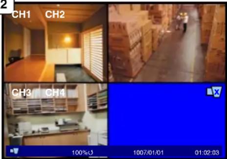
8CH STANDALONE DVR LOREX (FW:2.50.85 UCODE:86)
VIDEO: NTSC
DISK0: 78533MB HD7280PLAT20 NEW DISK
DISK1: NONE
DISK0: PRESS [PLAY] FORMAT [STOP] CAN
FORMAT ... DONE.
CD DRIVE: HL-ST DVD-RAM 1.07
| Network Settings | |
| Enable | Yes |
| Local Ip | |
| Port | 6341 |
| Mac Address | 12:24:56:76:9A:BC |
| Password | 111111 |
| DDNS Setup | |
| Video quality | High |
| Local IP | ||||
| IP Type | [DUGP] | |||
| IP Address | 0. | 0. | 0. | 0 |
| Gateway | 0. | 0. | 0. | 0 |
| Net Mask | 0. | 0. | 0. | 0 |
| Local IP | ||||
| IP Type | [DUKEP] | |||
| IP Address | 0. | 0. | 0. | 0 |
| Gateway | 0. | 0. | 0. | 0 |
| Net Mask | 0. | 0. | 0. | 0 |
| Local IP | |
| IP Type | [STATIC] |
| IP Address | 192.168.10.213 |
| Gateway | 192.168.10.1 |
| Net Mask | 255.255.255.0 |
| Network Settings | |
| Enable | Yes |
| Local Ip | |
| Port | 8841 |
| Mac Address | 12:34:56:78:9A:BC |
| Password | 111111 |
| DNS5 setup | |
| Video quality | High |
Exit & Discard Changes
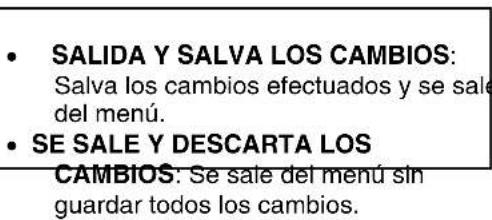
Time search
Normal Record Event
Time Record Event
Notion Record Event
sensor Record Event
Total Record Event
Backup
Time search
Normal Record Event
Time Record Event
Notion Record Event
sensor Record Event
Total Record Event
Backup
Domain Name: tomsmith
Password: (your password)
It's all on the Web!
- CAUTION
- Important Safeguards
- Installation
- Service
- Use
- General Precautions
- FCCCLASSBNOTICE
- Note:
- L200 Series Features
- Connections:
- Table of Contents
- Getting Started
- L200 Series - Front
- POWER/REC/PLAYLEDs -
- NAVIGATION CONTROLS/ENTER -
- L200 Series - Back
- Remote Control
- Mouse Control
- Mouse Controls
- DVR Setup
- DataPlayback
- Advanced Reservation Record using a mouse
- Viewing Screen Control
- Camera Installation
- InstallationWarnings:
- Camera Stand Installation:
- Connecting BNC Cameras
- Camera Connection Diagram
- Display Modes
- Initial Loading Sequence
- General Display Overview
- 1.CAMERA TITLE & RECORDING
- 4.DRIVE FULL INDICATOR -
- Camera Display Modes
- Onscreen Symbols - Channel Symbols
- Onscreen Symbols - Status Bar
- System Setup Controls
- Menu Navigation Controls
- Setup Menu - Options
- Using the Virtual Keyboard
- CAMERA SETUP
- CHANNEL
- DISPLAY
- BRIGHTNESS
- CONTRAST
- HUE
- SATURATION
- RECORD SETUP
- RECORD QUALITY
- EVENT REC DURATION
- RECORD SCHEDULE SUBMENU
- RECORD SCHEDULE
- RECORD SCHEDULE ENABLE
- SENSOR SETUP
- ALARM DURATION
- SENSOR - 1, 2, 3, 4
- MOTION DETECTION SETUP
- SENSITIVITY
- MOTION AREA SUBMENU
- Using the Front Panel Buttons:
- Using a Mouse:
- SCREEN SETUP
- BORDER
- VIDEO ADJUSTMENT SUBMENU
- SEQUENCE INTERVAL
- AUDIO SETUP
- RECORD
- MUTE
- INPUT/OUTPUT VOLUME
- SYSTEM MENU
- HARD DISK SETUP SUBMENU
- password CHANGE SUBMENU
- password ENABLE
- TIME SET SUBMENU
- SYSTEM EVENT LIST SUBMENU
- NETWORK SUBMENU
- DHCP SETUP
- STATIC SETUP
- 12
- 34
- NETWORK SUBMENU (CONT.)
- DDNS SETUP
- RS-485 SUBMENU
- PAN/TILT DEVICE SUBMENU
- F/W UPGRADE
- SEARCH MENU
- STATUS MENU
- FACTORY DEFAULT MENU
- EXIT MENU
- RECORDING
- Recording Schedule Symbols:
- SEARCH FUNCTION
- Time Search
- SEARCH TYPES
- RECORD EVENT LISTS
- Page 0001
- VIDEO PLAYBACK
- BACKUP FUNCTION
- USB MEMORY STICK BACKUP
- BACK-UP VIA CD-R/W* (OPTIONAL)
- USING THE BACK-UP FUNCTION
- FIRMWARE UPGRADE
- PTZ (PAN/TILT/ZOOM)
- Lorex Client Application
- PLAYER MODE
- PLAYBACK METHOD
- PLAYBACK
- Capture
- AUDIO FUNCTION
- Full Screen
- Aspect Ratio
- Split Mode
- Option Menu
- General Options
- Export
- Close Viewer
- BUTTON FUNCTION
- VIEWER MODE
- CONNECTING WITH VIEWER
- CONNECTING ON THE LAN:
- CONNECTING ON THE WAN (REMOITERLY OVER THE INTERNET):
- VIEWER MENU
- DVR Control
- Audio
- Local Recording
- OPTION FUNCTION
- Full Connectivity Diagram - Appendix #2
- Hard Drive Replacement - Appendix #3
- Removing the Back Cover and Installed Drive
- Setting the New Drive to Master
- Hard Drive Replacement (cont'd.)
- Installing the New Drive
- New Hard Drive Format
- RTC (Real Time Clock) Chip
- Troubleshooting - Appendix #4
- Problem:
- Check:
- Troubleshooting (cont'd.)
- Appendix #5 - Network Connectivity Overview
- IP & MAC Address (Step #2)
- Finding Your External IP Address
- Setting Up Your DDNS Account (Step #3)
- Setting Up Your DDNS Account (cont'd.)
- Router Port Forwarding (Step #4)
- DDNS Setup on the DVR (Step #5)
- Appendix #6 - PTZ Control
- Installing a PTZ (RS-485 Type) PTZ Camera:
- Appendix #7 - Connecting Motion / Alarm Device
- Installing a Sensor
- Appendix #8 - Initial Setup Menu Values
- Appendix #9 - HDD Usage Table
- VIDÉO ENREGISTREUR DES SURVEILLANCE NUMÉRIQUE
- AVEC DÉTECTION DE MOUVEMENT ET ENREGISTREMENT SONORE
- Guide d'instruction
- MENU DE DÉFAUT D'USINE
- search
- Recherche Horaire
- It's all on the Web!
Brand : Lorex
Model : L208D251
Category : Voice recorder