
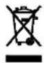
24 AF1 Nikon - Flash METZ - Free user manual and instructions
Find the device manual for free 24 AF1 Nikon METZ in PDF.
| Product type | Electronic flash (mecablitz) |
| Brand / Model | Metz 24 AF-1 N |
| Compatibility | Nikon TTL and i-TTL cameras |
| Power supply | 2 AA batteries/rechargeable batteries (LR6/HR6/KR6) – NiCd, NiMH, alkaline |
| Dimensions (L × H × D) | 64 × 95 × 67 mm |
| Weight (with batteries/rechargeable batteries) | 182 g |
| Guide number (ISO 100, 50 mm) | 24 |
| Color temperature | ~5,500 K |
| Flash duration | 1/500 s to 1/30,000 s |
| Recycling time (full power) | ~5 s (alkaline batteries) / ~6 s (NiMH rechargeable) |
| Battery life (full power) | ~200 flashes (alkaline) / ~250 flashes (NiMH) |
| TTL functions | i-TTL (Nikon), standard TTL, automatic fill-in |
| AF illuminator | Yes – for focusing in low light |
| Head orientation | Vertical up to 90° (click stops at 45°, 60°, 75°, 90°) |
| Synchronization | 1st curtain, 2nd curtain (REAR), slow sync (SLOW) |
| TTL flash exposure compensation | Manual, set on the camera (±1-2 stops) |
| Automatic power off (Auto-OFF) | Approximately 3 minutes standby |
| Firmware update | Possible via METZ customer service |
| Maintenance and cleaning | Soft, dry or silicone cloth – no detergent |
| Safety recommendations | Do not use near flammable gases, do not look directly into the flash, avoid high temperatures |
| Repairability and spare parts | Repair exclusively by METZ service – no user-serviceable parts |
Frequently Asked Questions - 24 AF1 Nikon METZ
User questions about 24 AF1 Nikon METZ
0 question about this device. Answer the ones you know or ask your own.
Ask a new question about this device
Download the instructions for your Flash in PDF format for free! Find your manual 24 AF1 Nikon - METZ and take your electronic device back in hand. On this page are published all the documents necessary for the use of your device. 24 AF1 Nikon by METZ.
USER MANUAL 24 AF1 Nikon METZ

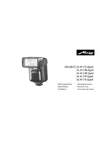
MECABLITZ 24 AF-1 C digital
24 AF-1 N digital
24 AF-1 O digital
24 AF-1 P digital
24 AF-1 S digital
Bedienungsanleitung
Operating Instructions
Mode d'emploi
Norme per l'uso
Handleiding
2.3 mecablitz 24 AF-1 O....61
2.4 mecablitz 24 AF-1 P....61
2.5 mecablitz 24 AF-1 S....62
Welcome to the large family of Metz customers! We congratulate you on purchasing this flash unit and thank you for your confidence in our products.
It is only natural that you should want to use your flash unit straight away. However, we recommend that you study these Operating Instructions beforehand to be able to fully exploit and utilize all the capabilities offered.
GB
This flash unit is only suitable for the following camera brands:
• 24 AF-1 C only for Canon EOS/Power shot cameras
• 24 AF-1 N only for Nikon TTL and iTTL-cameras
- 36 AF-4 O only for Olympus digital cameras with TTL flash control and flash socket system, as well as compatible digital cameras from Panasonic and Leica.
- 24 AF-1 P only for analogue and digital Pentax cameras with TTL or PTTL control and flash socket system, as well as compatible digital cameras from Samsung.
- 24 AF-1 S only for digital Sony alpha – reflex cameras with TTL-, TTL- pre-flash function and ADI metering as well as analogue and digital Konica – Minolta Dynax / Dimage cameras.
Contents
1 Safety instructions 84
2 Dedicated functions ..... 86
2.1 mecablitz 24 AF-1 C....86
2.2 mecablitz 24 AF-1 N....86
2.3 mecablitz 24 AF-1 O....87
2.4 mecablitz 24 AF-1 P 87
2.5 mecablitz 24 AF-1 \$ 88
3 Mounting the mecablitz. 88
3.1 Mounting the mecablitz on the camera ..... 88
3.2 Removing the mecablitz from the camera ..... 89
4 Power supply 90
4.1 Suitable batteries....90
4.2 Replacing batteries 90
4.3 Switching the flash unit on and off ..... 91
4.4 Auto OFF for the flash unit 91
5 Dedicated functions and flash mode ..... 92
5.1 Flash readiness indication 92
5.2 Automatic flash sync speed control ..... 92
5.3 Correct exposure indication ..... 93
5.4 Displays in the camera viewfinder ..... 93
5.4.1 mecablitz 24 AF-1 C....93
5.4.2 mecablitz 24 AF-1 N. 94
5.4.3 mecablitz 24 AF-1 O....94
5.4.4 mecablitz 24 AF-1 P 94
5.4.5 mecablitz 24 AF-1 S....95
5.5 AF auxiliary light 95
5.6 TTL flash mode 96
5.6.1 Automatic TTL fill-in flash in daylight. 97
5.6.2 Canon E-TTL flash mode....97
5.6.3 Nikon i-TTL flash mode 98
5.6.4 TTL flash mode with measurement pre-flash function (Olympus)....99
5.6.5 P-TTL flash mode (Pentax). 99
5.6.6 Pre-flash TTL and ADI metering (Sony)....100
5.6.7 Manual TTL flash exposure correction ..... 100
6 Programmed Auto Flash Mode ..... 101
7 Flash techniques ..... 101
7.1 Bounce flash 101
7.2 Flash synchronisation....102
7.2.1 Normal synchronisation..... 102
7.2.2 REAR - Second-curtain synchronisation ..... 103
7.2.3 Slow synchronisation / SLOW ..... 103
8 Maintenance and care 104
9 Technical data 104
1 Safety instructions
- The flash unit is exclusively intended and approved for photographic use!
- Never fire a flash in the vicinity of flammable gases or liquids (petrol, solvents, etc.)! DANGER OF EXPLOSION!
- Never take flash shots of car, bus or train drivers, or of motorcycle and bicycle riders, whilst they are travelling. They could be blinded by the light and cause an accident!
- Never fire a flash in the immediate vicinity of the eyes! Flash fired directly in front of the eyes of a person or animal can damage the retina and lead to severe visual disorders - even blindness!
- Only use the approved power sources listed in the Operating Instructions!
-
Do not expose batteries to excessive heat, sunshine, fire and the like!
-
Never throw exhausted batteries on to a fire!
- Exhausted batteries should be immediately removed from the flash unit. Lye leaking out of spent batteries will damage the unit.
- Never recharge dry-cell batteries!
- Do not expose the flash unit or battery charger to dripping or splashing water (such as rain)!
- Protect the flash unit from excessive heat and humidity! Do not store the flash unit in the glove compartment of a car!
-
Never place material that is impervious to light in front of, or directly on, the reflector screen. The reflector screen must be perfectly clean when a flash is fired. The high energy of the flash light will burn the material or damage the reflector screen if this is not observed.
-
Do not touch the reflector screen after a series of flash shots. Danger of burns!
- Never disassemble the flashgun! DANGER: HIGH VOLTAGE! There are no components inside the flashgun that can be repaired by a layman.
- When taking a series of flash shots at full light output and fast recycling times as provided by NiCad battery operation, make sure to observe an interval of at least 10 minutes after 15 flashes, otherwise the flash unit will be overloaded.
- The mecablitz may only be used in combination with a camera-integrated flash unit if the latter can completely be folded out!
- Quick changes in temperature may cause condensation. Therefore give the flashgun time to acclimatize!
2 Supported dedicated functions
2.1 mecablitz 24 AF-1 C
- Flash ready indication in camera viewfinder
• Automatic flash sync speed - TTL flash control
- E-TTL flash control
ΔManual TTL-flash exposure correction
ΔFlash exposure storage FE
x AF auxiliary light control
- Programmed auto flash mode
- Wake-up function for flash unit
Δ = Dedicated function is performed by the camera or must be set on the camera.
x = Some cameras only support the AF illuminator integrated in the camera.
2.2 mecablitz 24 AF-1 N
- Flash ready indication in camera viewfinder
• Automatic flash sync speed - TTL flash control
- i-TTL flash control
• Automatic TTL flash exposure correction
ΔManual TTL-flash exposure correction
- AF auxiliary light control
- Programmed auto flash mode
Δ1st or 2nd curtain synchronisation
- Wake-up function for flash unit
Δ= Dedicated function is performed by the camera or must be set on the camera.
x = Some cameras only support the AF illuminator integrated in the camera.
2.3 mecablitz 24 AF-1 O
- Flash ready indicator in camera viewfinder/camera display
• Automatic flash sync speed control - Four Thirds system compatible
• Automatic flash / triggering control - TTL flash control (TTL with pre-flash function)
• Automatic fill-in flash control
ΔManual flash exposure correction with TTL
ΔSynchronisation to the 1st or 2nd shutter curtain (2nd curtain / SLOW2)
x Auto-focus measurement flash control
ΔPre-flash function for reducing red-eye effect
- Wake-up function for flash unit
Δ= Dedicated function is performed by the camera or must be set on the camera.
x = Some cameras only support the AF illuminator integrated in the camera.
2.4 mecablitz 24 AF-1 P
- Flash ready indicator in camera viewfinder/camera display
- Exposure control indicator in the camera viewfinder with TTL
• Automatic flash sync speed control
• Automatic flash / triggering control - TTL flash control
- PTTL flash control
• Automatic TTL / P-TTL fill-in flash control
ΔManual flash exposure correction with TTL
• Auto-focus measurement flash control
ΔPre-flash function for reducing red-eye effect - Wake-up function for the flash unit
Δ= Dedicated function is performed by the camera or must be set on the camera.
2.5 mecablitz 24 AF-1 S
- Flash ready indicator in camera viewfinder
• Automatic flash sync speed control
• Automatic flash / triggering control - TTL flash control (standard TTL without measuring pre-flash function)
• Pre-flash TTL and ADI metering
• Automatic fill-in flash control
ΔManual flash exposure correction with TTL
ΔSynchronisation to the 1st or 2nd shutter curtain
• Auto-focus measurement flash control - Wake-up function for the flash unit
Δ= Dedicated function is performed by the camera or must be set on the camera.
3 Mounting the mecablitz
3.1 Mounting the mecablitz on the camera
Switch off camera and mecablitz with the main switch! mecablitz 24 AF-1 C, 24 AF-1 N and 24 AF-1 P
- Push the mecablitz with the connection foot as far as it will go into the camera accessory shoe. Then press the "LOCK button" to secure.
mecablitz 24 AF-1 S
- Push the mecablitz with the connection foot as far as it will go into the camera accessory shoe. The safety catch can be heard to snap into place on the hot shoe.
- Lightly press the unlatching button "PUSH" upward to clamp the mecablitz in the camera's accessory shoe.
mecablitz 24 AF-1 O
- Push the mecablitz with the connection foot as far as it will go into the camera accessory shoe. Then press the "LOCK button" to secure.
3.2 Removing the mecablitz from the camera
Turn off the camera and the mecablitz by their main switch.
mecablitz 24 AF-1 C, 24 AF-1 N and 24 AF-1 P
- Press both side plastic catches ▶◀ on the connection foot in the direction indicated by the arrows and pull off the mecablitz at the same time from the camera accessory shoe.
mecablitz 24 AF-1 S
- Press the unlatching button "PUSH" towards the flash unit and at the same time hold it lightly down until the "PUSH" button locks in place.
- Withdraw the mecablitz from the camera's accessory shoe.
mecablitz 24 AF-1 O
- Press both side plastic catches ▶◀ on the connection foot in the direction indicated by the arrows and pull off the mecablitz at the same time from the camera accessory shoe.
4 Power supply
4.1 Suitable batteries
The mecablitz can be operated with any of the following batteries:
- 2 NiCad batteries, type IEC KR6 (AA). They permit very fast recycling and are economical in use because they are rechargeable.
- 2 nickel metal hydride batteries IEC HR6 (AA). They have a significantly higher capacity than NiCad batteries and are less harmful to the environment (no cadmium).
- 2 alkaline manganese dry-cell batteries, type IEC LR6 (AA). Maintenance-free power source for moderate power requirements.
Do not use lithium batteries! Their higher cell voltage may damage the electronic system of the flash unit.
Remove the batteries from the mecablitz if the flash unit is not going to be used for an extended period of time.
4.2 Replacing batteries
The batteries are exhausted if the recycling time (elapsing from the triggering of a full-power flash to the moment the flash ready indicator lights up again) exceeds 60 seconds.
- Turn off the mecablitz by its main switch.
- Slide the battery compartment cover in the direction of the arrow.
- Insert the batteries lengthwise in conformity with the indicated battery symbols and close the battery compartment cover.
When loading batteries ensure correct polarity, as indicated by the symbols in the battery compartment.
Mixed up battery poles may destroy the flash unit! Replace all batteries at a time and make sure that the batteries are of the same brand and type and have the same capacity!
Exhausted batteries must not be thrown in the dustbin! Help protect the environment and dispose of run-down batteries at the appropriate collecting points.
4.3 Switching the flash unit on and off
The flash unit is switched on by its main switch. In the right "ON" position, the mecablitz is on. To turn off the flash unit reset the main switch to its "OFF" position.
4.4 Auto OFF for the flash unit
To save battery power and prevent inadvertent battery drain, the flash unit is factory-set to automatically switch to standby mode (Auto OFF) 10 minutes after
- being switched on,
- a flash is fired
• the shutter release is actuated - the camera's exposure metering system is switched off.
...The green flash-ready light is extinguished.
The flash unit can be reactivated by pressing the shutter release (wake up function).
The flash unit should always be turned off using the main switch if it is not going to be used for an extended period.
5 Dedicated functions and flash mode
5.1 Flash readiness indication
The flash readiness symbol lights up on the mecablitz when the flash capacitor is charged, thereby indicating that flashes can be fired for the next shot. Flash readiness is transmitted to the camera and displayed in the viewfinder (see camera manual).
GB
If a picture is shot before flash readiness is signalled in the camera's viewfinder, then the flash unit will not be triggered so that the exposure may be incorrect.

If flash readiness is established, a test flash can be triggered with the manual firing button on the mecablitz.
5.2 Automatic flash sync speed control
Depending on the camera model and the selected mode, the camera's shutter speed automatically changes to flash sync speed when flash readiness is reached (see operating instructions for the given camera).
Shutter speeds faster than the flash sync speed cannot be set or will automatically be changed to flash sync speed. Various cameras feature a sync speed range, e.g. 1/60th sec. to 1/250th sec. (see the camera's operating instructions).
The actual sync speed used by the camera depends on the camera mode, the prevailing ambient light and the focal length of the lens.
Shutter speeds that are slower than the flash sync speed can be used, depending on the operating mode selected on the camera.
5.3 Correct exposure indication
The "o.k." correct exposure confirmation briefly lights up on the mecablitz when the shot was correctly exposed in TTL flash mode.
If "o.k." is not indicated after an exposure, then this means that the shot was underexposed. The shot will then have to be repeated with the next smaller f-number (e.g. f/8 instead of f/11) or the distance to the subject or the reflecting surface (e.g. when bouncing the flash) must be shortened.
5.4 Displays in the camera viewfinder
The actual display in the camera viewfinder can deviate from the subsequent description or some symbols are only possible with certain camera models (see operating instructions for the given camera).
5.4.1 mecablitz 24 AF-1 C
- Flash symbol flashes:
User is requested to use or switch on the flash unit.
- Flash symbol lights up: mecablitz is ready for operation.
Some cameras have a warning function in the viewfinder to indicate incorrect exposure. For instance, if the f-number or shutter speed or both of them flash in the viewfinder, then this will indicate either under- or overexposure.
Basic information concerning incorrect exposure:
- In the event of overexposure: Do not use the flash!
- In the event of underexposure: Switch on the flash unit or mount the camera on a tripod and set a slower shutter speed.
The reasons for incorrect exposure can vary in the different exposure and automatic programmes.
5.4.2 mecablitz 24 AF-1 N
- Green flash symbol illuminated and ? blinks: User is requested to use or switch on the flash unit.
- Green flash symbol illuminated: Flash unit is ready for firing.
- Green flash symbol remains illuminated after shooting or is briefly switched off: The shot was correctly exposed.
- A arrow symbol links after shooting: The shot was underexposed.
5.4.3 mecablitz 24 AF-1 O
- Flash symbol flashes: Prompt indicating that the flash unit is to be switched on and used or that the flash unit is not flash ready (on some cameras).
- Flash symbol is illuminated: The flash unit is flash-ready (on some cameras).
- Flash symbol is not illuminated: In the case of flash-ready flash units: The camera suppresses flash execution when the ambient light is too bright.
5.4.4. mecablitz 24 AF-1 P
- Flash symbol is illuminated: The flash unit is flash-ready.
- Flash symbol is not illuminated: The flash unit is not flash-ready.
Or in the case of a flash-ready flash unit: The camera suppresses flash execution when the ambient light is too bright.
5.4.5 mecablitz 24 AF-1 S
- Flash symbol flashes: The flash unit is not flash-ready.
- Flash symbol is illuminated: The flash unit is flash-ready.
For information applicable to the displays in the viewfinder of your camera model, refer to the camera's operating instructions.
5.5 AF auxiliary light
The AF auxiliary light is activated by the camera electronics when the ambient lighting conditions are insufficient for automatic focusing. The AF beam emitter then projects a striped pattern on to the subject, and the camera uses this pattern to focus automatically.
To enable activation of the AF auxiliary light by the camera, the camera lens must be set to AF. On the camera, the AF mode "Single-AF" or "ONE-SHOT-AF" must be selected. Low-speed zoom lenses may significantly reduce the distance range of the AF auxiliary light.
The striped pattern of the AF auxiliary light only supports the camera's central AF sensor. When using cameras with several AF metering areas we therefore recommend to activate the camera's central AF metering zone.
Some cameras may only activate the AF illuminator integrated in the camera. In such an event, the AF auxiliary light emitter of the mecablitz will not be activated.
Please refer to the corresponding information given in operating instructions for the individual camera.
5.6 TTL flash mode
The mecablitz is only suitable for the TTL flash mode. The TTL flash mode is a very simple way to achieve excellent flash shots. In this mode exposure readings are taken by a sensor built into the camera which measures the light reaching the film through the camera lens (TTL). The electronic control circuit within the camera transmits a stop signal to the mecablitz as soon as the film has been exposed by the correct amount of light, thereby instantly interrupting the flash. The advantage of this flash mode is that all factors influencing correct exposure of the film (filters, change of aperture and focal length with zoom lenses, extensions for close-ups, etc.) are automatically taken into account. You need not worry about setting the flash, the camera's electronic system automatically determines the correct amount of flash light required.
If flash exposure was correct, the "o.k." exposure confirmation lights up.
The TTL flash mode is supported by all camera modes (e.g. Full Auto Mode, Program P, Aperture Priority Mode "Av" or "A", Shutter Priority Mode "Tv" or "S", Programmed Image Control Modes, Manual Mode "M", etc.).
To test the TTL function a film must be loaded in the camera. When selecting the film please check whether limits regarding maximum film speed are applicable to the given camera when in TTL mode (refer to the camera's operating instructions).
5.6.1 Automatic TTL fill-in flash in daylight
Most camera models automatically activate the fill-in flash mode when in Full Auto Mode, Program P, and the Programmed Image Control Modes in daylight (see the camera's operating instructions).
Fill-in flash overcomes troublesome dense shadows and produces a more balanced exposure between subject and background with contre-jour shots. The camera's computer-controlled metering system sets the most suitable combination of shutter speed, working aperture and flash output.

Ensure that the contre-jour light source does not shine directly into the lens as this will mislead the camera's TTL metering system!
In this instance there is no setting or display on the mecablitz for automatic TTL fill-in flash.
5.6.2 Canon E-TTL flash mode
The E-TTL flash mode is an advanced variant of the "normal" TTL flash mode. Prior to shooting, the reflection of the subject is measured by way of a preflash. The camera evaluates the reflected preflash light so that the subsequent flash exposure is optimally adapted to the prevailing photographic situation (see operating instructions of your camera).
Settings and displays
- Switch on the flash unit and the camera.
- Lightly touch the camera's shutter release for data exchange between flash unit and camera.
- The E-TTL flash mode is automatically activated when the camera supports this mode. E-TTL then lights up on the flash unit.
FE flash exposure storage
Some Canon cameras offer the possibility of FE flash exposure storage. This is supported by the flash unit in the E-TTL flash mode.
FE flash exposure storage in E-TTL mode permits the amount of light required for the subsequent shot to be determined and stored prior to exposure. This can be expedient when flash exposure has to be adapted to specific details that may not necessarily be identical with the main subject.
Focus the camera's AF sensor metering area on the zone whose flash exposure is to be predetermined. When the FE button on the camera is actuated (the designation may vary with individual camera models - see camera's operating instructions) the flash unit will fire an FE test flash. The electronic measuring circuit inside the camera assesses the reflected light of the FE test flash to determine the light output required for the subsequent exposure. The main subject can thereafter be focused with the AF sensor metering area of the camera. When the shutter release is pressed the picture will be exposed with the previously determined light output.
Due to system-inherent reasons any changes in the light situation after the FE test flash has been fired will not be taken into account when the picture is shot.
Some cameras do not support FE flash exposure storage in the "green" full auto mode or programmed image control modes (see camera's operating instructions).
5.6.3 Nikon i-TTL flash mode
i-TTL flash mode is an advanced variant of the standard TTL flash control of analog cameras. When shooting a picture, several weakly visible preflashes are fired by the flash unit prior to exposure. The camera then evaluates the reflected preflash light so that the subsequent flash exposure is opti-
mally adapted to the prevailing photographic situation.
When the TTL flash mode is selected, the flash unit automatically activates standard TTL or i-TTL flash mode, depending on the type of camera.
Flash exposure memory
Some cameras have flash exposure memory (FV memory). This is supported by the flash unit in i-TTL flash mode. It can be used to define and store the exposure level for the subsequent shot before the shot is actually taken. This can be useful when, for example, the flash exposure has to be adjusted to specific details that may not necessarily be identical with the main subject.
This function is activated on the camera, in some instances as an individual function.
5.6.4 TTL flash mode with measurement pre-flash function (Olympus)
During the shot and before the actual exposure, one or more pre-flashes are executed by the flash unit. The camera evaluates the measurement pre-flash and controls the light output of the flash unit for the main flash.
The flash unit is set to this mode by the camera automatically.
5.6.5 P-TTL flash mode (Pentax)
With P-TTL flash mode a measuring pre-flash is fired before the actual exposure. The camera evaluates the measurement pre-flash and controls the light output for the main flash.
The flash unit is set to this mode by the camera automatically.
5.6.6 Pre-flash TTL and ADI metering (Sony)
These types of flash mode are used with Sony digital cameras and adjusted on the camera.
During shooting, a measurement pre-flash is executed before the actual exposure. The camera evaluates the measurement pre-flash and controls the light output for the main flash. In the case of ADI metering, additional distance data from the lens is incorporated into the flash exposure process. The flash unit automatically adapts itself to the mode selected on the camera.
5.6.7 Manual TTL flash exposure correction
The TTL auto flash mode of most cameras is matched to a 25% degree of light reflection by the subject (average amount of light reflected by flash-shot subjects). Consequently, a dark background that absorbs a great deal of light, or a bright background that reflects a great deal of light, can result in
under- or overexposure, respectively.
To offset this effect a correction value can be set on some cameras to manually match the TTL flash exposure to the photographic situation. The actual extent of correction depends on the contrast prevailing between subject and background. The correction value is set on the camera. Please refer to the camera's operating instructions for details concerning the settings.
A dark subject in front of a bright background: Positive correction value (approx. 1 to 2 EV). Light subject in front of a dark background: Negative correction value (approx. -1 to -2 EV).
Exposure correction by changing the lens diaphragm is not possible because the camera's automatic exposure system will automatically regard the changed diaphragm as the normal working aperture.
After the exposure do not forget to reset the TTL flash exposure correction back to the normal value on the camera!
6 Programmed Auto Flash Mode
In the programmed auto flash mode the camera automatically controls the aperture, the shutter speed, and the mecablitz for optimal results in most photographic situations, including fill-in flash.
Settings on the camera
Set your camera to Full Auto Mode, Program P or a Programmed Image Control Mode (landscape, portraiture, sport, etc.). Select the auto-focus mode on the camera.
Settings on the flash unit
Having completed the above settings, you can commence flash photography as soon as the mecablitz indicates flash readiness.
7 Flash techniques
7.1 Bounce flash
Photos shot with full frontal flash are easily recognized by their harsh, dense shadows. This is often associated with a sharp drop in light from the foreground to the background. This phenomenon can be avoided with bounce flash because the diffused light will produce a soft and uniform rendition of both the subject and the background. For this situation the reflector is turned in such a manner that the flash is bounced off a suitable reflective surface (e.g. ceiling or wall of the room).
The reflector can be turned vertically up to 90°.
When turning the reflector vertically, it is essential to ensure that it is moved by a sufficiently wide angle so that direct light can no longer fall on the subject.
Consequently, always turn the reflector at least to the 60° lock-in position.
The light bounced off the reflecting surfaces produces a soft and uniform illumination of the subject. The reflecting surface must be white or have a neutral colour, and it must not be structured, e.g. wooden beams in a ceiling as these might cause shadows.
For colour effects just select the reflective surface in the desired colour.
Take into account that the maximum flash range is considerably diminished when bouncing the flash. The following rule of thumb will help you determine the
maximum flash range for a room of normal height:
Maximum flash range = guide number /( flash - to - subject distance × 2)
7.2 Flash synchronisation
7.2.1 Normal synchronisation
In normal synchronisation the mecablitz is triggered at the beginning of the exposure time (1st curtain synchronisation). Normal synchronisation is the standard mode on all cameras, and is suitable for most flash shots. Depending upon the given mode, the camera is changed over to flash sync speed, the customary one being between 1/30th sec. and 1/125th sec. (see the camera's operating instructions). No settings have to be made on the mecablitz, nor is there any display for this mode.
7.2.2 REAR - Second-curtain synchronisation
Some cameras offer the facility of second-curtain synchronisation (REAR mode) triggering the mecablitz by the end of the exposure time. Second-curtain synchronisation is particularly advantageous when using slow shutter speeds (slower than 1/30 sec.) or when shooting moving objects that have their own source of light. Second-curtain synchronisation gives a more realistic impression of movement because the light streaks behind the light source instead of building up in front of it, as is the case when the flash is synchronised with the 1st shutter curtain! Depending on its operating mode, the camera uses shutter speeds slower than its sync speed.

The REAR function is only possible with cameras featuring this facility. The corresponding setting is made on the camera (see operating instructions of the given camera).
7.2.3 Slow synchronisation / SLOW
In certain operating modes, some cameras permit slow flash synchronisation (SLOW) which will provide added prominence to the background at lower ambient light levels. This is achieved by matching the shutter speed to the ambient light. Accordingly, shutter speeds slower than the flash sync speed are automatically adjusted by the camera. Some cameras automatically activate SLOW synchronisation in connection with certain programs (e.g. aperture priority "Av" or "A", night shots program, etc.) or permit slow synchronisation to be set (see camera's instruction manual).

Use a tripod to avoid camera shake with slow shutter speeds!
8 Maintenance and care
Remove any grime and dust with a soft, dry or silicon-treated cloth. Never use detergents that could damage plastic parts.
Forming the flash capacitor
The flash capacitor incorporated in the flash unit undergoes a physical change when the flash unit is not switched on for prolonged periods of time. For this reason it is necessary to switch on the mecablitz for approx. 10 minutes every 3 months. The batteries must supply sufficient power for flash readiness to be indicated within 1 minute after the mecablitz was switched on.
Metz does not accept any liability for faulty functions or damage to the mecablitz caused by the use of accessories from other manufacturers!
9 Technical data
The flash unit can be updated by the METZ customer service department.
Tilting range and locking positions of flash head: vertically 45° - 60° - 75° - 90°
Flash duration: 1/500 s - 1/30,000 s
Colour temperature: approx. 5500 K
Synchronisation: Low-voltage ignition
Number of flashes (at full light output):
approx. 200 with high-capacity alkaline manganese batteries approx. 250 with NiMH batteries (2100 mAh)
Recycling time (at full light output):
approx. 5 s with high-capacity alkaline manganese batteries approx. 6 s with NiMH batteries (2100 mAh)
Dimensions (w x h x d): 64 x 95 x 67 mm
Weight: 182 g without batteries
Included: mecablitz, Operating Instructions
Disposal of batteries
Do not dispose of spent batteries with domestic rubbish.
Please return spent batteries to collecting points should they exist in your country. Please return only fully discharged batteries. Normally, batteries are fully discharged if:
• They no longer function properly after prolonged use.
To ensure short-circuit safety please cover the battery poles with adhesive tape.
Errors excepted. Subject to changes!
Premessa
2.5 mecablitz 24 AF-1 S .....112
3 Montaggio del mecablitz .....112
Your Metz product was developed and manufactured with high-quality materials and components which can be recycled and / or reused.
This symbol indicates that electrical and electronic equipment must be disposed of separately from normal garbage at the end of its operational lifetime.
Please dispose of this product by bringing it to your local collection point or recycling centre for such equipment.
This will help to protect the environment in which we all live.
①
Metz - always first class.
CE
D F NL GB I E
709 47 0261.A1


- CONTENTS
- 1 SAFETY INSTRUCTIONS
- 2 SUPPORTED DEDICATED FUNCTIONS
- 2.1 MECABLITZ 24 AF-1 C
- 2.2 MECABLITZ 24 AF-1 N
- 2.3 MECABLITZ 24 AF-1 O
- 2.4 MECABLITZ 24 AF-1 P
- 2.5 MECABLITZ 24 AF-1 S
- 3 MOUNTING THE MECABLITZ
- 3.1 MOUNTING THE MECABLITZ ON THE CAMERA
- MECABLITZ 24 AF-1 S
- MECABLITZ 24 AF-1 O
- 3.2 REMOVING THE MECABLITZ FROM THE CAMERA
- 4 POWER SUPPLY
- 4.1 SUITABLE BATTERIES
- DO NOT USE LITHIUM BATTERIES! THEIR HIGHER CELL VOLTAGE MAY DAMAGE THE ELECTRONIC SYSTEM OF THE FLASH UNIT
- 4.2 REPLACING BATTERIES
- 4.3 SWITCHING THE FLASH UNIT ON AND OFF
- 4.4 AUTO OFF FOR THE FLASH UNIT
- 5 DEDICATED FUNCTIONS AND FLASH MODE
- 5.1 FLASH READINESS INDICATION
- 5.2 AUTOMATIC FLASH SYNC SPEED CONTROL
- 5.3 CORRECT EXPOSURE INDICATION
- 5.4 DISPLAYS IN THE CAMERA VIEWFINDER
- 5.4.1 MECABLITZ 24 AF-1 C
- 5.4.2 MECABLITZ 24 AF-1 N
- 5.4.3 MECABLITZ 24 AF-1 O
- MECABLITZ 24 AF-1 P
- 5.4.5 MECABLITZ 24 AF-1 S
- 5.5 AF AUXILIARY LIGHT
- 5.6 TTL FLASH MODE
- 5.6.1 AUTOMATIC TTL FILL-IN FLASH IN DAYLIGHT
- 5.6.2 CANON E-TTL FLASH MODE
- SETTINGS AND DISPLAYS
- FE FLASH EXPOSURE STORAGE
- 5.6.3 NIKON I-TTL FLASH MODE
- FLASH EXPOSURE MEMORY
- 5.6.4 TTL FLASH MODE WITH MEASUREMENT PRE-FLASH FUNCTION (OLYMPUS)
- 5.6.5 P-TTL FLASH MODE (PENTAX)
- 5.6.6 PRE-FLASH TTL AND ADI METERING (SONY)
- 5.6.7 MANUAL TTL FLASH EXPOSURE CORRECTION
- 6 PROGRAMMED AUTO FLASH MODE
- SETTINGS ON THE CAMERA
- SETTINGS ON THE FLASH UNIT
- 7 FLASH TECHNIQUES
- 7.1 BOUNCE FLASH
- 7.2 FLASH SYNCHRONISATION
- 7.2.1 NORMAL SYNCHRONISATION
- 7.2.2 REAR - SECOND-CURTAIN SYNCHRONISATION
- 7.2.3 SLOW SYNCHRONISATION / SLOW
- 8 MAINTENANCE AND CARE
- FORMING THE FLASH CAPACITOR
- 9 TECHNICAL DATA
- DISPOSAL OF BATTERIES
- PREMESSA
Brand : METZ
Model : 24 AF1 Nikon
Category : Flash