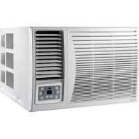
ADP 12T - Air Conditioning DAITSU - Free user manual and instructions
Find the device manual for free ADP 12T DAITSU in PDF.



| Product type | Mobile monobloc air conditioner (reversible) |
| Brand | Daitsu |
| Model | ADP 12T |
| Power supply | 220-240 V ~ 50 Hz |
| Operating modes | Cool, Dry, Fan, Heat |
| Temperature range (cool) | 17 °C to 30 °C |
| Temperature range (dry) | 10 °C to 30 °C |
| Temperature range (heat) | 17 °C to 30 °C |
| Fan speeds | High, Medium, Low |
| Timer | Programmable on/off from 0 to 24 h |
| Digital display | Yes |
| Remote control | Yes (with alkaline batteries included) |
| Air filter | Washable, cleaning recommended every 2 weeks |
| Exhaust | Flexible duct 500-2000 mm, adapters for temporary or permanent installation |
| Sliding window kit | Included, adjustable from 67.5 cm to 123 cm |
| Drainage pump | Yes, max discharge height 3.5 m |
| Continuous drainage | Possible with additional hose |
| Internal water tank | With full level indicator and safety stop |
| Supplied accessories | Duct, adapter A and B, wall outlet, screws, remote control, batteries, drainage hose |
| Safety | Automatic shutoff if tank full, frost protection (heat mode), network impedance ≤0.4582 Ω |
Frequently Asked Questions - ADP 12T DAITSU
User questions about ADP 12T DAITSU
0 question about this device. Answer the ones you know or ask your own.
Ask a new question about this device
Download the instructions for your Air Conditioning in PDF format for free! Find your manual ADP 12T - DAITSU and take your electronic device back in hand. On this page are published all the documents necessary for the use of your device. ADP 12T by DAITSU.
USER MANUAL ADP 12T DAITSU
PLEASE READ THIS OPERATION MANUAL BEFORE USING THE AIR CONDITIONER.
CONTENIDOS
natural_image
Line drawing of a hand holding a device with a label 'H/V' on its side (no other text or symbols)
natural_image
Line drawing of a wall-mounted air conditioner unit with a handle, no text or symbols presentnatural_image
Technical line drawings of mechanical components and structural details (no text or symbols)
natural_image
Technical line drawing of a portable air conditioner unit with ventilation grilles and a handle (no text or symbols)natural_image
Pure mechanical diagram showing a pipe with a cross-shaped component and diagonal lines (no text or symbols)IMPORTANTE
natural_image
Line drawing of a portable air conditioner unit with cooling fins and ventilation slots (no text or symbols)natural_image
Line drawing of a hand holding a device with a label 'H/V' on its side (no other text or symbols)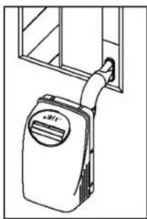
natural_image
Line drawing of a wall-mounted air conditioner unit with a handle, no text or symbols presentnatural_image
Technical line drawings of mechanical components and structural details (no text or symbols)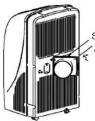
natural_image
Technical line drawing of a portable air conditioner unit with ventilation grilles and a handle (no text or symbols)natural_image
Pure mechanical diagram showing a pipe with cross-shaped constraints and a vertical bar, without any text or symbols.IMPORTANTE
natural_image
Line drawing of a refrigerator with doors open and visible blades (no text or symbols)natural_image
Line drawing of a mechanical device with a handle and ventilation slots (no text or symbols)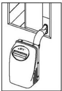
natural_image
Line drawing of a wall-mounted air conditioner unit with a handle and vent, mounted on a window (no text or symbols)natural_image
Pure mechanical diagram showing a pipe with cross-shaped and straight lines, no text or symbols presentINSTALLATION
natural_image
Line drawing of a refrigerator with doors open and visible door, no text or symbols presentDÉPANNAGE
Operation panel of the air conditioner 34
Operating instructing for the air conditioner 35-36
Installation 37-38
Maintenance 39
Trouble shooting 40
SAFETY RULES
1- Do not connect unit to any ac socket in disrepair or with connections.
2- Do not use in the following locations:
- Next to source of fire
- An area where oil is likely to splash.
- An area exposed to direct sunlight.
- An area where water is likely to splash.
- Near a bath, a shower or a swimming pool.
- In the green house.
3- Never insert your fingers or any foreign objects into the air outlet. Take special care to warn children of these dangers.
4- Always store the unit upright in order to maintain the compressor in a proper condition.
5- Be sure to unplug the unit before cleaning.
6- The heater must not be located immediately below a socket outlet.
7- If the appliance is covered, there is a risk of overheat.
8- If the supply tool of this appliance is damaged, it must be replaced by a repair shop appointed by the manufacturer, because special purpose tools are required.
Note: The air-conditioner can be connected only to a supply with system impedance no more than 0.4582 ohm. But the system impedance should be at least 0.257ohm (For 9000Btu/h models) or 0.208ohm(For 12000Btu/h models).
In case necessary, please consult your supply authority for system impedance information.
NAMES OF PARTS
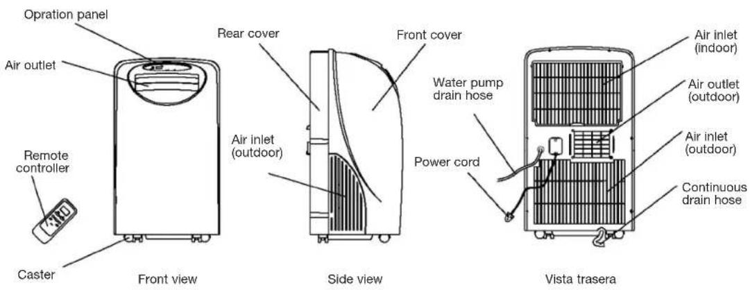
ACCESSORIES
| PARTS | PARTS NAME | QUANTITY |
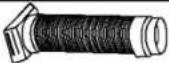 | Duct 1 | |
 | Adaptor A (for permanent ductmounting) 1 | |
 | Adaptor B (for temporary ductmounting) 1 | |
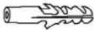 | Wall plug 4 | |
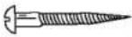 | Screws 4 | |
 | Alkaline batteries 2 | |
 | Remote controller 1 | |
 | Water pump drain hose 1 |
- Check all the accessories are included in the package and please refer to the installation instructions for their usage.
OPERATION PANEL OF THE AIR CONDITIONER
Cooling and heating

Operating panel
Cooling only type
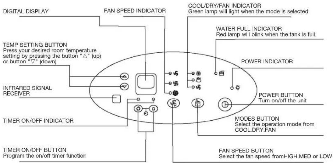
Operating panel
OPERATING INSTRUCTING FOR THE AIR CONDITIONER
Before starting this unit
1- Select a suitable location, make sure you have easy access to an electrical outlet.
2- Install the Flexible Exhaust Hose and the Adjustable Window Slider Kit as depicted in Fig.
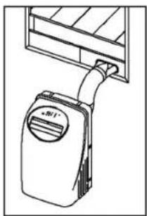
natural_image
Line drawing of a door handle with a label 'R1' and a circular badge, no readable text or symbols present.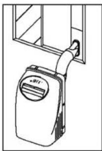
natural_image
Line drawing of a wall-mounted air conditioner unit with a handle, mounted on a cabinet (no text or symbols)Note: Step 2 is required only while using the "cooling mode".
3- Plug the unit into a 220V-240V-50Hz grounded electrical outlet.
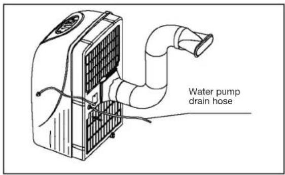
4- Make sure the water pump drain hose is correctly installed.
5- Press the "on/off" button to turn on the unit.
(1) Before use
Dehumidifying and Cooling Operations
- The operating range for dehumidifying is 10^ C- 30^ C/ 50^ F- 86^ F, and the operating range for cooling operating is 17^ C- 30^ C/ 63^ F- 86^ F.
- If the cooling or dehumidifying operations have been switched off and need switching on again in a short time, allow approximately three minutes for the cooling or dehumidifying operations to resume.
- Make sure the water pump drain hose is correctly connected to the unit.
Power supply:
- Insert the AC Power Plug to a AC socket.
- Do not connect the air conditioner to a multiple socket outlet which is also being used for other electrical appliance.
- Be sure the power supply is AC 220V-240V\~50Hz.
OPERATING INSTRUCTING FOR THE AIR CONDITIONER
(2) Cooling operation
- Press the "MODE" button several times until the "COOL" indicator light comes on.
- Press the "TEMP SETTING" buttons "▲" or "▼" to select your desired room temperature. (17°C-30°C/63°F-86°F)
- Press the "FAN SPEED" button to choose the fan speed.
(3) Dehumidifying operation
- Press the "MODE" button several times until the "DRY" indicator light comes on.
- Press the "TEMP SETTING" buttons "▲" or "▼" to select your desired room temperature. (10°C-30°C/50°F-86°F)
- The fan will run at a fixed speed at this setting.
- Keep windows and doors closed for the best dehumidifying effect.
- Do not put the duct to window.
(4) Heating operation (Cooling only type without heat feature)
- Press the "MODE" button several times until the "HEAT" indicator light comes on.
- Press the "TEMP SETTING" buttons "▲" or "▼" to select your desired room temperature. (17°C-30°C/63°F-86°F)
- Press the "FAN SPEED" button to choose the fan speed.
- Do not put the duct to window.
(5) Fan operation
- Press the "MODE" button several times until the "FAN" indicator light comes on.
- Press the "FAN SPEED" button to choose the fan speed.
- Do not put the duct to window.
(6) Timer operation
Setting the on timer:
- Press the "TIMER ON" button when the air conditioner is off. Select the time you need the unit start to operate.
- The Operation Paned Window will display "ON"
- The starting time is adjustable from 0.00 to 24.
Setting the off timer:
- Press the "TIMER OFF" button when the air conditioner is on. Select the time you need the unit turn off. The Operation Panel Window will display "OFF".
- The turning off time is adjustable from 0.00 to 24.
(7) Water pump drainage
- Connect the water pump drain hose to the unit before operate. When the water level of the internal water tank reaches a predetermined level, the water pump will be activated and drain the condensed water outside through the connected drain hose. The maximum delivery lift is 3.5m. (Under this condition, attach the rubber blockage to the back hole to prevent continuous drainage.)
(8) Continuous drainage
- When you plan to leave this unit unused for a long time, remove the rubber blockage form the back hole and attach a section of the continuous drain hose to drain hose connector. All the water in the water tank would drain outside through the drain hose. (Under this condition, the water pump is not activated.)
INSTALLATION
(1) Important
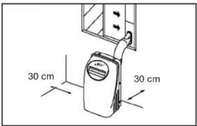
Install the mobile ir conditioner in a flat and spacious location where the air outlets will not be covered up. A minimum clearance of 30cm from a wall or other obstacles should be kept. The appliance shall not be used in the laundry. The plug shall accessible after appliance is positioned. Wiring shall be done according to National rules.
(2) Duct mount instructions
natural_image
Technical line drawings of mechanical components and structural details (no text or symbols)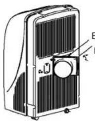
natural_image
Technical line drawing of a portable air conditioner unit with ventilation grilles and a handle (no text or symbols)Exhaust Air Oulet Duck
Temporary
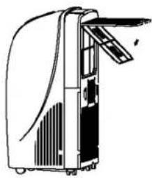
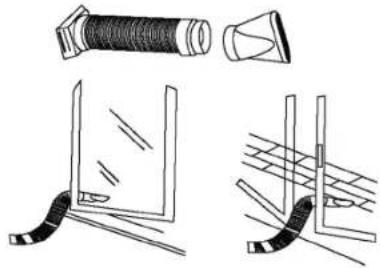
1- Attach one end of the duct to the exhaust air outlet of the mobile air condition, first fit the left side of the duct on the exhaust air panel, then the right side duct. Push it downwards, be sure to fix thoroughly. (See the figures)
2- Attach the other end of the duct to adaptor B.
3- Put the end of duct to a nearby window.
Permanent
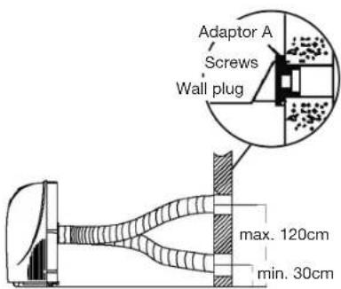
1- Attach one end of the duct to the exhaust air outlet of the mobile air conditioner. According to the arrow direction, first fit the left side of the duct on the exhaust air panel, then the right side duct. Push it downwards, be sure to fix thoroughly. (See the figures)
2- Install the adaptor A onto the wall by using 4 wall plug and screws, be sure to fix thoroughly. (See the figures)
3- Attach the other end of the duct to adaptor A.
4- Cover the hole using the adaptor cap when not in use.
- The duct can be compressed or extended between 500mm and 2000mm, but it is desirable to keep the duct length to a minimum.
natural_image
Pure electrical circuit lines without any symbolsIMPORTANT
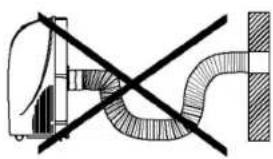
Do not over bend the duct (see figure)
INSTALLATION
Window Kit Installation
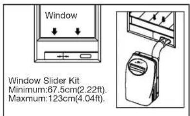
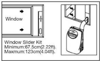
Your window kit has been designed to fit most standard Vertical and horizontal window applications. However, it may be necessary for you to improvise/modify some aspects of the installation procedures for certain types of window. Please refer to Fig. for minimum and maximum window openings.
Drain Tank Safety Feature
This unit is equipped with a internal water tank, two full-safe switch mechanisms, one is used to control the water pump drainage, the other is used to monitor the water level inside the internal water tank. When the water level reaches a predetermined level, the full-safe switch mechanism is activated. The digital display shows P1 and the water full indicator light illuminates. Carefully move the unit outside, remove the rubber blockage from the back drainage hole and drain the water off. The unit will continue operating properly.
MAINTENANCE
IMPORTANT
1- Be sure to unplug the unit before cleaning.
2- Do not use gasoling, thinner or other chemicals to clean the unit.
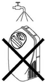
3- Do not wash the unit directly under a tap or using a hose. The electrical cause danger.
4- If the power cord is damaged, it should be repaired by manufacture or its agency.
Air filter
- Clean the air filter at least once every two weeks to prevent inferior fan operation because of dust.
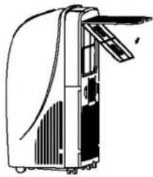
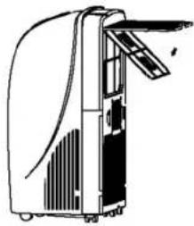
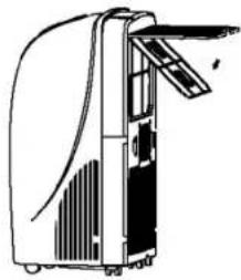
Pull out the filter cover and remove the air filter from the filter cover.
Wash the air filter by immersing it gently in warm water (about 40^ C/104°F) with a neutral detergent. Rinse the filter and dry it in a shady place.
Attach the air filter to the filter cover using the attachment hooks on the inner surface of the cover. Put the filter cover back to the unit.
Removal
- Cleaning
- Mounting
Unit enclosure
- Use a lint-free cloth soaked with neutral detergent to clean the unit enclosure. Finished by a dry clean cloth.
natural_image
Line drawing of a refrigerator with doors open and visible door, no text or symbols presentTROUBLE SHOOTING
| Troubles | Possible causes Suggest remedies | |
| Unit does not start when pressing 1/0 button | Water full indicator blinks, water tank is full. | Dump the water in the water tank. |
| Room temperature is higher than the set temperature.(Heating mode) | Reset the temperature. | |
| Room temperature is lower than the set temperature.(Cooling mode) | Reset the temperature. | |
| Not cool enough | The windows or doors in the room are not closed. | Make sure all the windows anddoors are closed. |
| There are heat sources inside the room. | Remove the heat sources if possible. | |
| Exhaust air duct is not connected or blocked. | Connect the duct and makesure it can function properly. | |
| Temperature setting is too high. | Decrease the set temperature. | |
| Air filter is blocked by dust. Clean the air filter. | ||
| Power shut off at heating mode | The automatic over heat protection function. When the temperature at the air outlet exceed 70^/158^ , the device willst op. | Switch on again after the unit has cool down. |
| Noisy or vibration | The ground is not level or not flat enough. | Place the unit on a flat, levelground if possible. |
| Gurgling sound | The sound comes from the flowing of the refrigerant inside the air-conditioner. | It is normal. |


- CONTENIDOS
- IMPORTANTE
- INSTALLATION
- DÉPANNAGE
- SAFETY RULES
- NAMES OF PARTS
- ACCESSORIES
- OPERATION PANEL OF THE AIR CONDITIONER
- OPERATING INSTRUCTING FOR THE AIR CONDITIONER
- Before starting this unit
- Before use
- Cooling operation
- Dehumidifying operation
- Heating operation (Cooling only type without heat feature)
- Fan operation
- Timer operation
- Water pump drainage
- Continuous drainage
- Important
- Duct mount instructions
- Temporary
- Permanent
- IMPORTANT
- Window Kit Installation
- Drain Tank Safety Feature
- MAINTENANCE
- Air filter
- Removal
- - Cleaning
- - Mounting
- Unit enclosure
- TROUBLE SHOOTING
Brand : DAITSU
Model : ADP 12T
Category : Air Conditioning