KSV36AI41 - Fridge BOSCH - Free user manual and instructions
Find the device manual for free KSV36AI41 BOSCH in PDF.
User questions about KSV36AI41 BOSCH
0 question about this device. Answer the ones you know or ask your own.
Ask a new question about this device
Download the instructions for your Fridge in PDF format for free! Find your manual KSV36AI41 - BOSCH and take your electronic device back in hand. On this page are published all the documents necessary for the use of your device. KSV36AI41 by BOSCH.
USER MANUAL KSV36AI41 BOSCH
Free-standing appliance
Using the installation instructions ..... 8
Installation location 8
Installing appliances next to each other 9
Changing over the door hinges ...... 9
Changing the door handle 10
Fitting the wall spacer 10
Aligning the appliance 10
text_image
Illustration showing a hand holding an open book with a curved arrow pointing to a grid-like document, indicating a transformation or mapping.Using the installation instructions

text_image
Illustration showing a hand holding a folded document with a curved arrow pointing to a grid-like panel, indicating transformation or mapping.Please fold out the illustrated last page. These installation instructions refer to several models.
The diagrams may differ.
Installation location
A dry, well ventilated room is suitable as an installation location. The installation location should not be exposed to direct sunlight and not placed near a heat source, e.g. a cooker, radiator, etc. If installation next to a heat source is unavoidable, use a suitable insulating plate or observe the following minimum distances from the heat source:
■ 3 cm to electric or gas cookers.
■ 30 cm to an oil or coal-fired cooker.
The floor of the installation location must not give way; if required, reinforce floor. If the floor is uneven, compensate with supports.
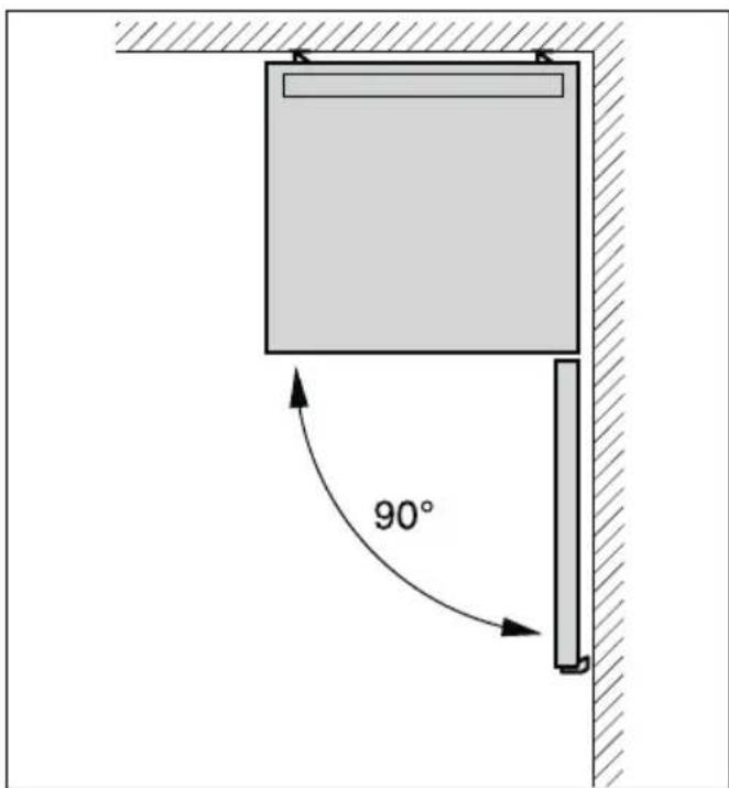
Distance from wall
When installing the appliance, ensure that the door can be opened by 90°.
text_image
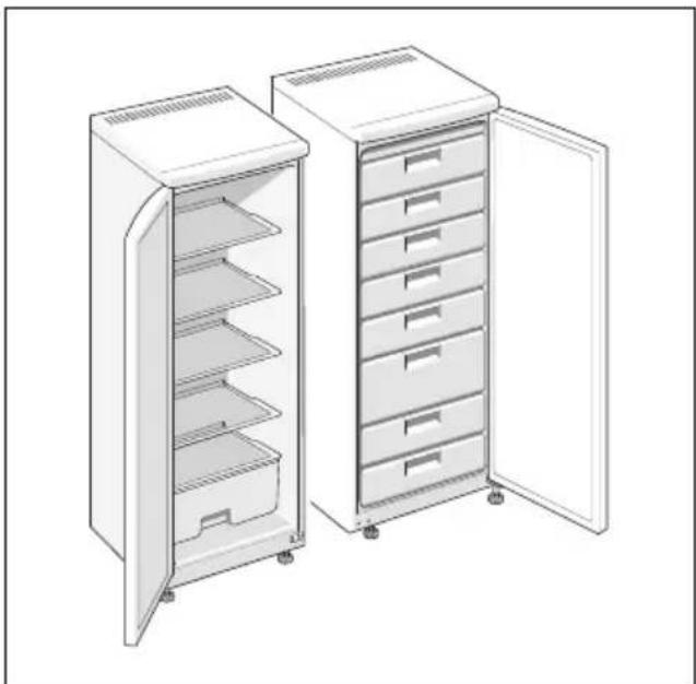
90°Installing appliances next to each other
Fig. 3
When installing two appliances, ensure that the refrigerator is on the left and the freezer is on the right.
The right side panel of the refrigerator is heated slightly. This prevents condensation from forming between the appliances.
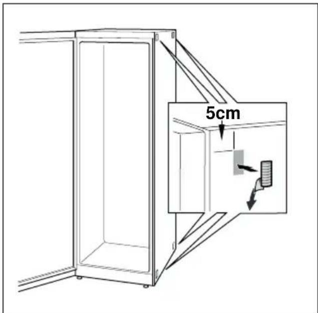
Attaching spacers
Fig. 4
- On the right side of the refrigerator degrease the adhesive areas with petroleum ether or spirit.
- Stick spacers in all four corners at a distance of 5 cm from the side edges to ensure a minimum gap between the appliances.
Note
You can purchase a connection set from your dealer.
Changing over the door hinges
(if required)
We recommend that you have the door hinges changed over by our customer service. You can find out the costs for changing over the door hinges from your appropriate customer service.

Warning
While changing over the door hinges, ensure that the appliance is not connected to the power supply. Pull out the mains plug beforehand. To prevent damaging the back of the appliance, place adequate padding underneath. Carefully place the appliance on its back.
Change over the door hinges in numerical sequence. Fig. 1
Note
If the appliance is placed on its back, ensure that the wall spacer is not fitted.
Changing the door handle
(if required)
Fig. 2 A/B
Change the door handle in numerical sequence.
Fitting the wall spacer
Fig. 5
If available:
Fit wall spacers to obtain the indicated energy absorption of the appliance.
A reduced wall gap will not restrict the function of the appliance. The energy absorption may then change slightly.
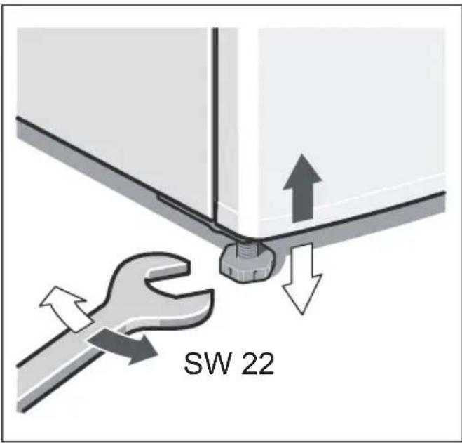
Aligning the appliance
Place the appliance in the designated location and align. The appliance must be level. If the floor is uneven, use the front height-adjustable feet. Adjust the height-adjustable feet with a wrench.
Note
The appliance must be upright. Please align it with a spirit level.
text_image
SW 22text_image
Illustration showing a hand holding a folded document with a curved arrow pointing to a grid layout, alongside an open notebook with text pages.text_image
Illustration showing a hand holding an open book with a curved arrow pointing to a grid-like document, indicating a transformation or mapping.text_image
Illustration showing a hand holding an open book with a curved arrow pointing to a grid-like document, indicating a transformation or mapping process.text_image
Illustration showing a hand holding an open document with a curved arrow pointing to a grid-like panel, indicating a transformation or mapping process.text_image
Illustration showing a hand holding an open document with a curved arrow pointing to a grid-like panel, indicating a transformation or mapping process.text_image
Illustration showing a hand holding a folded document with a curved arrow pointing to it, indicating a transformation or mapping process.text_image
Illustration showing a hand holding an open document with a curved arrow pointing to a grid-like panel, indicating transformation or mapping.text_image
Illustration showing a hand holding an open document with a grid layout and an arrow indicating direction or transformation.text_image
Illustration showing a hand holding an open notebook with a curved arrow pointing to a grid-like document, indicating a transformation or mapping.text_image
Illustration showing a hand holding an open document with a curved arrow pointing to a grid-like panel, indicating a transformation or mapping process.text_image
Illustration showing a hand holding a folded document with a curved arrow pointing to a grid layout, alongside an open notebook with text pages.text_image
Diagram illustrating safety warning and hazard of a refrigerator with labeled components and symbols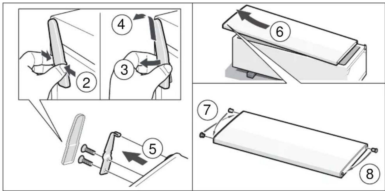
text_image
Diagram illustrating eight steps of a mechanical device operation, showing hand positioning and folding operations.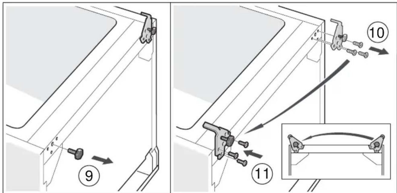
text_image
Technical diagram showing mechanical assembly steps with numbered instructions and magnified detail view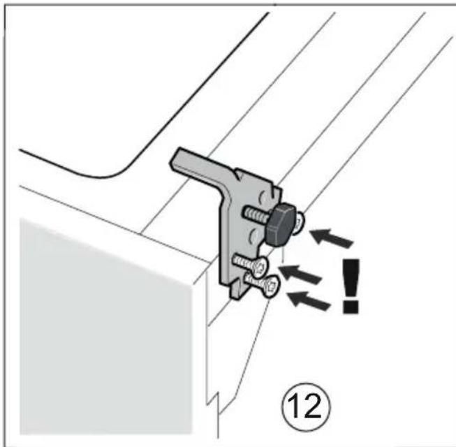
text_image
Technical diagram showing a mechanical clamp or bracket assembly with directional arrows and a circled number 12, likely indicating a warning or instruction.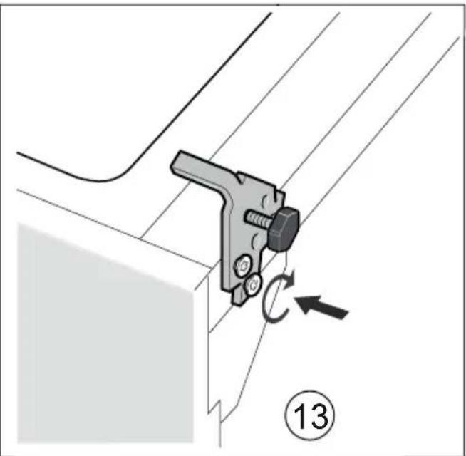
natural_image
Mechanical assembly diagram showing a bracket with a lever and rotating component, labeled with number 13 (no text or symbols on the diagram itself)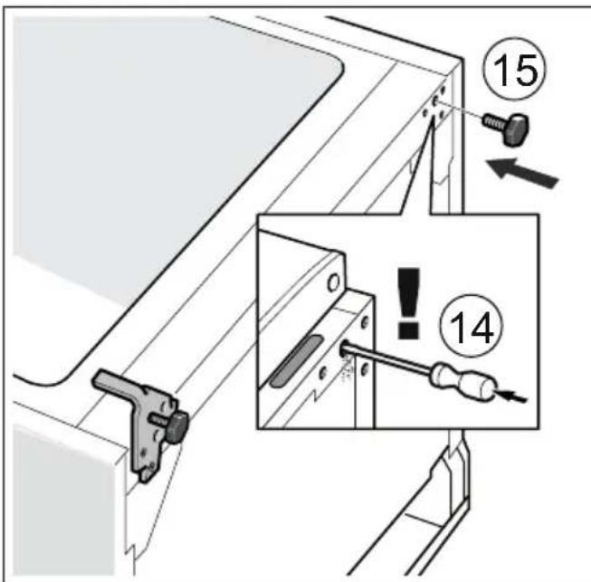
text_image
Technical diagram showing mechanical assembly with numbered components and warning labels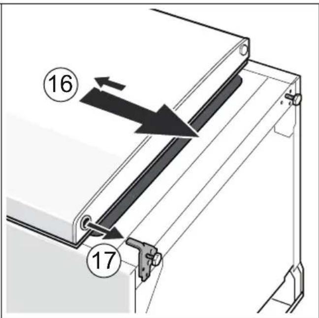
text_image
Technical diagram showing a mechanical assembly with numbered components and directional arrows indicating motion or movement.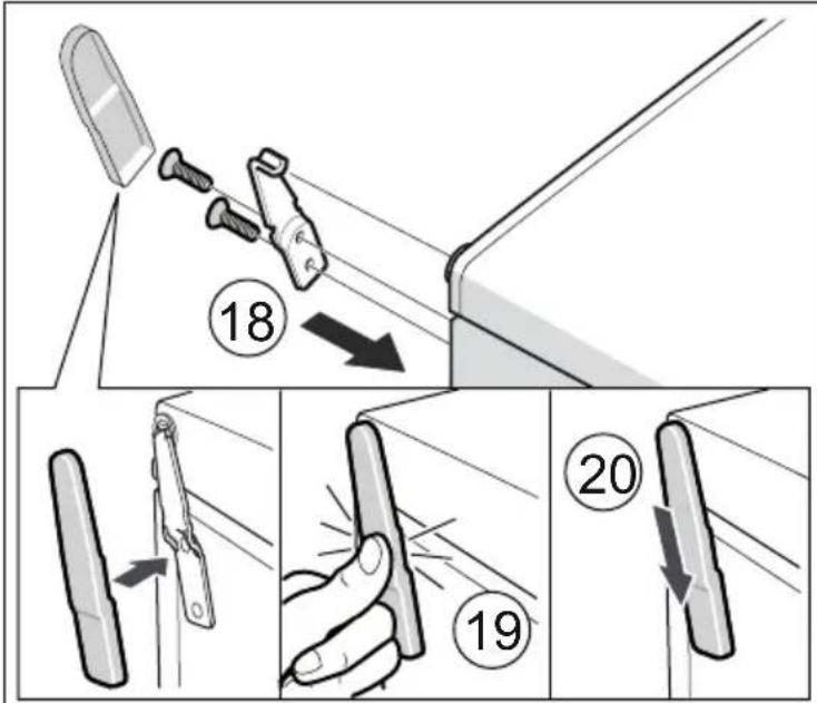
text_image
Diagram illustrating a door handle technique with numbered steps and directional arrows indicating movement or positioning.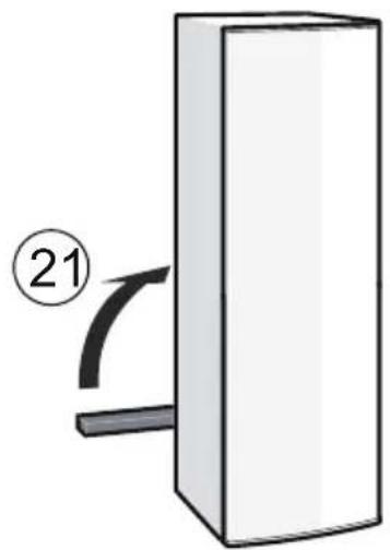
natural_image
Simple diagram of a rectangular block with a curved arrow and number 21, no text or symbols present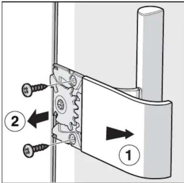
text_image
Technical diagram showing mechanical assembly with labeled parts and directional arrows indicating movement or force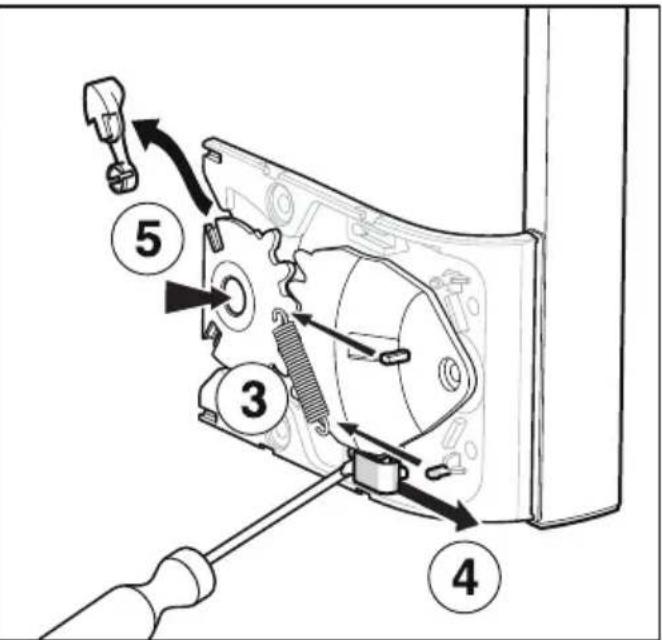
text_image
Technical diagram showing mechanical assembly with numbered components and directional arrows indicating motion or assembly steps.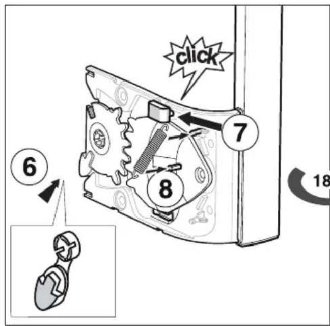
text_image
click 6 7 8 18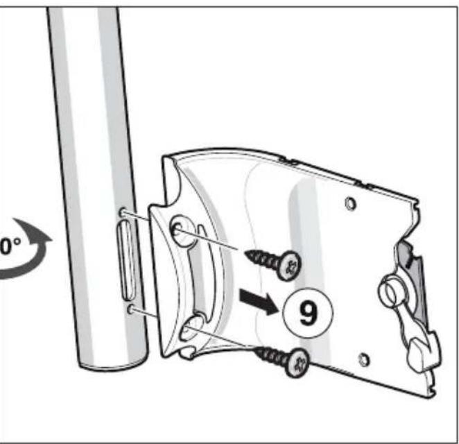
text_image
0° 9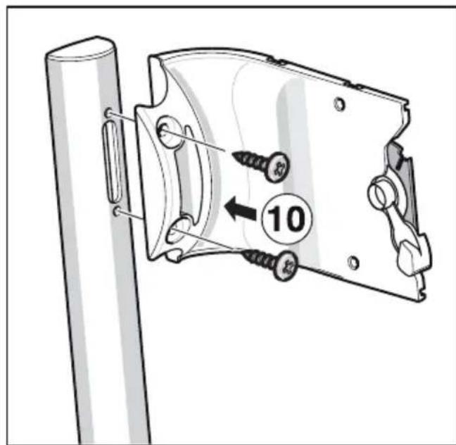
text_image
10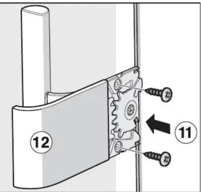
text_image
Technical diagram showing mechanical assembly with numbered components and directional arrows indicating movement or assembly.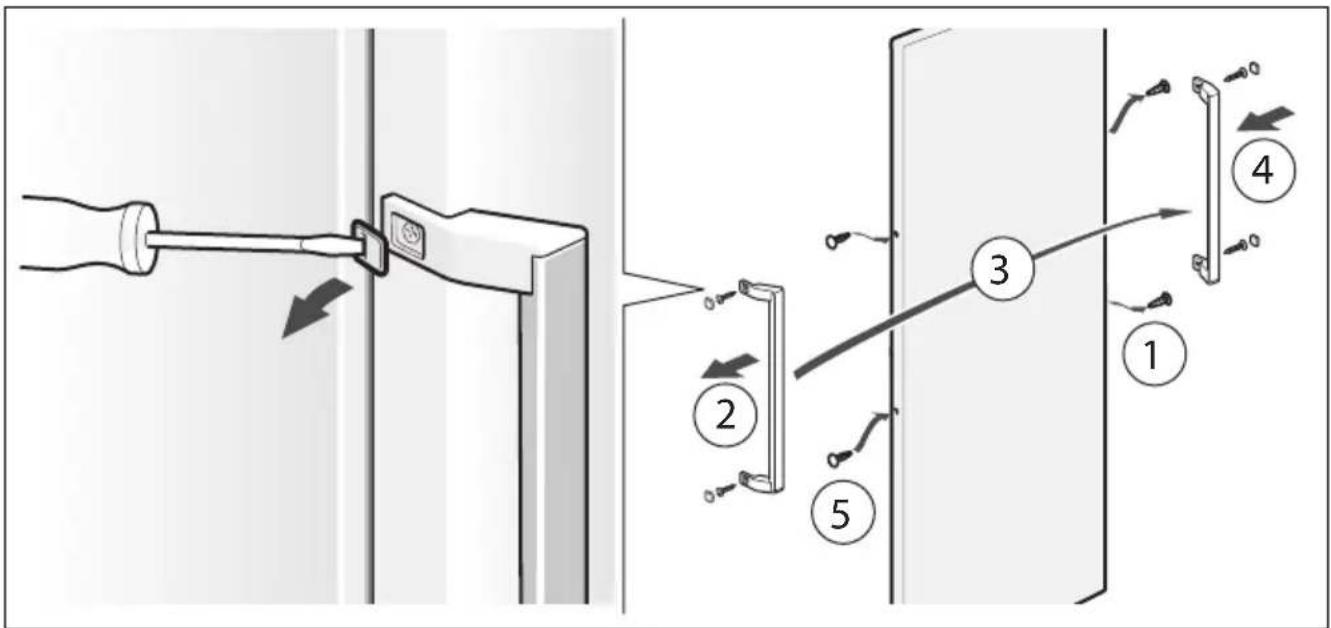
text_image
Diagram illustrating a door lock mechanism with numbered steps from pin 1 to pin 4, showing hand placement and adjustment.2/B
natural_image
Illustration of two open refrigerator units with different internal compartments (no text or symbols)3
text_image
5cm4
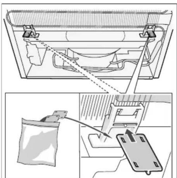
natural_image
Technical diagram showing a mechanical assembly with a bag and a clamp, no visible text or symbols5