IC-M510 - Marine VHF transceiver ICOM - Free user manual and instructions
Find the device manual for free IC-M510 ICOM in PDF.


User questions about IC-M510 ICOM
0 question about this device. Answer the ones you know or ask your own.
Ask a new question about this device
Download the instructions for your Marine VHF transceiver in PDF format for free! Find your manual IC-M510 - ICOM and take your electronic device back in hand. On this page are published all the documents necessary for the use of your device. IC-M510 by ICOM.
USER MANUAL IC-M510 ICOM
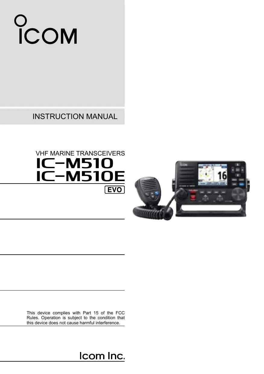
This device complies with Part 15 of the FCC Rules. Operation is subject to the condition that this device does not cause harmful interference.
Thank you for choosing this Icom product. This product was designed and built with Icom's state of the art technology and craftsmanship. With proper care, this product should provide you with years of trouble-free operation.
Important
READ ALL INSTRUCTIONS carefully and completely before using the transceiver.
SAVE THIS INSTRUCTION MANUAL —
This instruction manual contains important operating instructions for the IC-M510/IC-M510E.
This instruction manual includes some functions that are usable only when they are preset by your dealer.
Ask your dealer for details.
Explicit definitions
| WORD | DEFINITION |
| △WARNING! | Personal injury, fire hazard or electric shock may occur. |
| CAUTION | Equipment damage may occur. |
| NOTE | Recommended for optimum use. No risk of personal injury, fire or electric shock. |
lcom is not responsible for the destruction, damage to, or performance of any lcom or non-lcom equipment, if the malfunction is because of:
- Force majeure, including, but not limited to, fires, earthquakes, storms, floods, lightning, other natural disasters, disturbances, riots, war, or radioactive contamination.
- The use of Icom transceivers with any equipment that is not manufactured or approved by Icom.
Features
- Fixed mount Class D DSC marine VHF Transceiver
- Integrated Wireless LAN for connection with RS-M500.
NMEA 2000 connectivity and 2 way Hailer/RX Hailer function. - AIS information display input from the built-in AIS receiver* or an external NMEA sentence.
*May not be built-in, depending on the transceiver version.
New Sleek Design
- Wide (nearly 180 degree) viewing angle color TFT LCD with night mode.
- Simplified navigation function.
- Clear, Loud Audio
- White light backlit keys for increased visibility in low-light and dark conditions.
- Integrated GPS receiver.
The European version can select the EUR, UK, NLD, and FRG channels.
Icom and the Icom logo are registered trademarks of Icom Incorporated (Japan) in Japan, the United States, the United Kingdom, Germany, France, Spain, Russia, Australia, New Zealand, and/or other countries.
AQUAQUAKE is a trademark of Icom Incorporated.
COMMANDMIC is a trademark of Icom Incorporated.
NMEA 2000 and NMEA 0183 are trademarks of the National Maritime Electronics Association, Inc.
Android is a trademark of Google, LLC.
IOS is a trademark or registered trademark of Cisco in the U.S. and other countries and is used under license.
All other products or brands are registered trademarks or trademarks of their respective holders.
In case of emergency
If your vessel requires assistance, contact other vessels and the Coast Guard by sending a distress call on Channel 16 or transmit your Distress call using Digital Selective Calling (DSC) on Channel 70.
Using Channel 16
- Push [16/C] to switch to Channel 16.
-
While holding down [PTT], give the appropriate information as follows:
-
"MAYDAY MAYDAY MAYDAY."
- "THIS IS" (name of vessel).
- Say your call sign or other indication of the vessel (AND your 9 digit DSC ID, if you have one).
- “LOCATED AT” (your position).
State the nature of the distress and assistance required. - Give any other information which might facilitate the rescue.
Using Digital Selective Calling
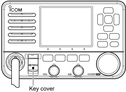
- Lift up the key cover, hold down [DISTRESS] for 3 seconds until the 3 short beeps and then one long beep sound.
- Wait for an acknowledgment from another station.
- After the acknowledgment is received, Channel 16 is automatically selected.
- Hold down [PTT], then transmit the appropriate information as listed above.
Radio operation warning

WARNING
Icom requires the radio operator to meet the FCC Requirements for Radio Frequency Exposure. An omnidirectional antenna with gain not greater than 9 dBi must be mounted a minimum of 5 meters (measured from the lowest point of the antenna) vertically above the main deck and all possible personnel. This is the minimum safe separation distance estimated to meet all RF exposure compliance requirements. This 5 meter distance is based
on the FCC Safe Maximum Permissible Exposure (MPE) distance of 3 meters added to the height of an adult (2 meters) and is appropriate for all vessels.
For watercraft without suitable structures, the antenna must be mounted so as to maintain a minimum of 1 meter vertically between the antenna, (measured from the lowest point of the antenna), to the heads of all persons AND all persons must stay outside of the 3 meter MPE radius.
Do not transmit with radio and antenna when persons are within the MPE radius of the antenna, unless such persons (such as driver or radio operator) are shielded from antenna field by a grounded metallic barrier. The MPE Radius is the minimum distance from the antenna axis that person should maintain in order to avoid RF exposure higher than the allowable MPE level set by FCC.
FAILURE TO OBSERVE THESE LIMITS MAY ALLOW THOSE WITHIN THE MPE RADIUS TO EXPERIENCE RF RADIATION ABSORPTION WHICH EXCEEDS THE FCC MAXIMUM PERMISSIBLE EXPOSURE (MPE) LIMIT.
IT IS THE RESPONSIBILITY OF THE RADIO OPERATOR TO ENSURE THAT THE MAXIMUM PERMISSIBLE EXPOSURE LIMITS ARE OBSERVED AT ALL TIMES DURING RADIO TRANSMISSION. THE RADIO OPERATOR IS TO ENSURE THAT NO BYSTANDERS COME WITHIN THE RADIUS OF THE MAXIMUM PERMISSIBLE EXPOSURE LIMITS.
Determining MPE Radius
THE MAXIMUM PERMISSIBLE EXPOSURE (MPE) RADIUS HAS BEEN ESTIMATED TO BE A RADIUS OF ABOUT 3 M PER OET BULLETIN 65 OF THE FCC.
THIS ESTIMATE IS MADE ASSUMING THE MAXIMUM POWER OF THE RADIO AND ANTENNAS WITH A MAXIMUM GAIN OF 9 dBi ARE USED FOR A SHIP MOUNTED SYSTEM.
IC-M510 RF Safety warning
An internal Wireless LAN module and an antenna are supplied with the IC-M510. To comply with FCC/ISED RF Exposure for the installed Wireless LAN unit, the device should be installed and operated with a minimum distance of 20~cm between the device and all persons. No other transmitting antenna is permitted to be located within 20~cm of the device.
This equipment has been tested and found to comply with the limits for a Class B digital device, pursuant to part 15 of the FCC Rules. These limits are designed to provide reasonable protection against harmful interference in a residential installation. This equipment generates, uses, and can radiate radio frequency energy and, if not installed and used in accordance with the instructions, may cause harmful interference to radio communications. However, there is no guarantee that interference will not occur in a particular installation. If this equipment does cause harmful interference to radio or television reception, which can be determined by turning the equipment off and on, the user is encouraged to try to correct the interference by one or more of the following measures:
- Reorient or relocate the receiving antenna.
- Increase the separation between the equipment and receiver.
- Connect the equipment into an outlet on a circuit different from that to which the receiver is connected.
- Consult the dealer or an experienced radio/TV technician for help.
CAUTION: Changes or modifications to this transceiver, not expressly approved by Icom Inc., could void your authority to operate this transceiver under FCC regulations.
Information FCC
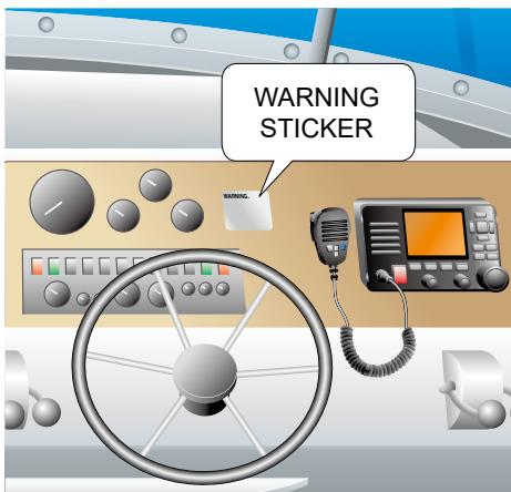
A WARNING STICKER is supplied with the USA version transceiver.
To comply with FCC regulations, this sticker must be affixed in such a location as to be readily seen from the operating controls of the radio as in the diagram to the right. Make sure the chosen location is clean and dry before applying the sticker.
Precautions
WARNING! NEVER connect the transceiver directly to an AC outlet. This may cause a fire or an electric shock.
WARNING! NEVER connect the transceiver to a power source of more than 16 V DC such as a 24 V battery. This connection could cause a fire or damage the transceiver.
WARNING! NEVER reverse the DC power cable polarity. This could cause a fire or damage the equipment.
WARNING! NEVER cut the DC power cable between the DC power connector on the transceiver's rear panel and the fuse holder. If an incorrect connection is made after cutting, the transceiver may be damaged.
WARNING! NEVER operate the transceiver during a lightning storm. It may result in an electric shock, cause a fire or damage the transceiver. Always disconnect the power source and antenna before a storm.
WARNING! NEVER place the transceiver where normal operation of the vessel may be hindered, or where it could cause bodily injury.
CAUTION: DO NOT place or leave the transceiver in areas with temperatures below -20^ or above +60^ (-4^ or above +140^) , or in areas subject to direct sunlight, such as a dashboard.
CAUTION: DO NOT use harsh solvents such as Benzine or alcohol when cleaning. This could damage the equipment surfaces. If the surface becomes dusty or dirty, wipe it clean with a soft, dry cloth.
NEVER place the transceiver in an insecure place to avoid inadvertent use by unauthorized persons.
BE CAREFUL! The transceiver's rear panel will become hot when transmitting continuously for long periods of time.
BE CAREFUL! The transceiver meets IPX8 requirements for waterproof protection. However, once the transceiver or microphone has been dropped, or the waterproof seal is cracked or damaged, waterproof protection cannot be guaranteed.
NOTE: Install the transceiver and/or microphone more than 1 meter from the vessel's magnetic navigation compass.
Wireless LAN information
Precautions on using the wireless LAN
- We recommend that users with pacemakers take precautions to be sure that this device does not cause them a problem because of electromagnetic interferences.
- Do not use this device near microwave ovens. A microwave oven may cause electromagnetic interference to the communications through this device.
- Do not modify the device. The device warranty does not cover any problems caused by unauthorized modification.
Wireless LAN installation location
Have the following installation conditions under consideration so that the communication range and speed are not affected.
Install the device in a stable place where there is no danger of falling or vibration.
- Do not place anything on top of this device.
- The communication range expands in an open space. However, in such location as warehouses with metallic walls, the walls may cause the radio waves to reflect.
Radio waves may pass through a wall or window, but not through metal. Some concrete walls are metal reinforcing structures, and may intercept the communication.
Heat absorbing glass or IR reflecting glass may intercept the communication.
- Communication may not be able to be performed with a wireless LAN installed on a different floor.
Precautions
The installation of this equipment should be made in such a manner as to respect the EC recommended electromagnetic field exposure limits. (1999/519/EC)
The maximum RF power available from this device is 25 watts. The antenna should be installed as high as possible for maximum efficiency and the installation height should be at least 1.76 meters above any accessible position. In the case where an antenna cannot be installed at a reasonable height, then the transmitter should neither be continuously operated for long periods if any person is within a distance of 1.76 meters of the antenna, nor operated at all if any person is touching the antenna.
It is recommended that antenna of a maximum gain of 3 dB is used. If higher gain antenna is required then please contact your Icom distributor for revised installation recommendations.
Operation:
The exposure to RF electromagnetic field is only applicable when this device is transmitting. This exposure is naturally reduced due to the nature of alternating periods of receiving and transmitting. Keep your transmissions to the minimum necessary.
Disposal

The crossed-out wheeledbin symbol on your product, literature, or packaging reminds you that in the European Union, all electrical and electronic products, batteries, and accumulators
(rechargeable batteries) must be taken to designated collection locations at the end of their working life. Do not dispose of these products as unsorted municipal waste. Dispose of them according to the laws in your area.
About CE and DOC
CE Hereby, Icom Inc. declares that the versions of IC-M510E which have the "CE" symbol on the product, comply with the essential requirements of the Radio Equipment Directive, 2014/53/EU, and the restriction of the use of certain hazardous substances in electrical and electronic equipment Directive, 2011/65/EU. The full text of the EU declaration of conformity is available at the following internet address: https://www.icomjapan.com/support/
About UKCA DOC
To obtain the UKCA Declaration of Conformity, please contact Icom UK Limited by email at info@icomuk.co.uk or alternatively call + 44(0) 1227 741741.
For European versions:
The following caution is printed on the labels of the transceiver.
CAUTION
AVOID TOUCHING REAR PANEL DURING PROLONGED USE.
This is because the transceiver's rear panel will become hot when continuously transmitting for long periods of time.
■ Recommendation
CLEAN THE TRANSCEIVER AND MICROPHONE THOROUGHLY WITH FRESH
WATER after exposure to saltwater, and dry it before operating. Otherwise, the transceiver's keys and switches may become unusable, due to salt crystallization.
NOTE: If the transceiver's waterproof protection appears defective, carefully clean it with a soft, damp (fresh water) cloth, then, dry it before operating.
The transceiver may lose its waterproof protection if the case or microphone is cracked or broken, the microphone connector is not screwed in completely, or the transceiver has been dropped.
Contact your Icom distributor or your dealer for advice.
Key icon description
The keys are described in this manual as follows:
The keys that have words or letters on them are described with the characters "[ ].
Example: [MENU], [CLEAR]
The Software Keys are described with the icon such as Finish or DTRS. The function of the keys are shown at the bottom of the display. Push the key below the desired function.
You can use the following keys on the Menu screen.
| FUNCTION | ACTION |
| Select | Push [▼] or [▲], or rotate [CH/ENT]. |
| Enter | Push [ENT], or [CH/ENT]. |
| Go to the next tree level | Push [ENT], [▶], or [CH/ENT]. |
| Go back to the previous tree level | Push [CLEAR], or [▲]. |
| Cancel | Push [CLEAR] or Cancel. |
| Exit | Push [MENU] or Exit. |
Information:
In this instruction manual, the transceiver model names are described as shown below.
U.S.A.: USA
Europe: EUR, General
Germany: FRG
Netherlands: NLD
U.K.:UK
Table of contents
Important.
Explicit definitions.
Features
In case of emergency..
■ Radio operation warning.
■ Avertissement pour les opérateurs radio
FCC information.
Information FCC.
Note. vi
Precautions vi
■ Wireless LAN information. vii
■ Précautions .vii
Information sur le réseau local sans fil
■ Installation note. ix
Disposal ix
■ About CE and DOC. ix
About UKCA DOC.. ix
■ Recommendation. x
Key icon description. x
1 OPERATING RULES. 1
2 PANEL DESCRIPTION 2
■ Front panel. 2
■ Speaker Microphone. 3
■ Function Display (INFO screen)......4
■ Software Keys. 6
3 PREPARATIONS 8
■ Entering the MMSI code. 8
■ Entering the ATIS ID (For NLD and FRG versions) 9
4 BASIC OPERATIONS 10
Selecting a channel. 10
■ Weather channels and Weather Alert (For only the USA versions) 11
Adjusting the volume/squelch/ backlight/display mode 12
Setting the Call channel 13
Receiving and transmitting. 13
AquaQuake Water Draining function. 14
■ Editing a channel name. 14
■ Microphone Lock function 15
5 SCAN OPERATION. 16
■ Scan types 16
Setting Favorite channels. 17
Starting a scan (Except for the NLD version) 17
6 DUALWATCH/TRI-WATCH 18
■ Description 18
Operation 18
7 DIGITAL SELECTIVE CALLING (DSC) 19
DSC address ID 19
■ Entering the position and time. 20
■ Sending DSC calls (Distress) 21
■ Sending DSC calls (other) 25
Receiving DSC calls (Distress) 35
Receiving DSC calls (other) 38
DSC Log. 43
■ Multiple-task mode 44
■ DSC Settings. 46
Making an Individual call to an AIS target 48
8 AIS FUNCTION 50
About AIS 50
■ AIS classes 50
Using the Plotter screen. 51
Using the AIS list screen 54
Setting a Friend. 56
About the Detail screen. 57
■ AIS settings. 59
9 OTHER FUNCTIONS 62
Waypoint 62
MOB (Man Overboard). 65
■Anchor Watch. 66
■ Navigation 67
Lost target 71
Using the Intercom. 72
Using the RX Hailer. 73
Using the Hailer. 74
Using the Horn function. 75
Using the Voice Scrambler. 76
Command microphone operation.... 77
10 MENU SCREEN 79
Using the Menu screen. 79
■ Menu items description 82
11 WLAN SETTING 88
■Turning the WLAN function ON.....88
■ Setting up the IC-M510/IC-M510E
WLAN mode. 88
Using a mobile device as a microphone 92
NMEA over WLAN settings 93
Reset the WLAN settings. 93
■ WLAN Information. 93
12 CONNECTIONS AND
MAINTENANCE 94
Supplied accessories 94
■ Fuse replacement 94
■ Cleaning. 94
Connections 95
Connecting to the MA-510TR. 97
■ Mounting the transceiver. 97
MBF-7/MBF-9 installation. 98
■ Microphone installation 99
13 SPECIFICATIONS AND OPTIONS101
■ Specifications. 101
Dimensions 105
■ Options. 106
14 TROUBLESHOOTING 107
Troubleshooting 107
Resetting the MMSI code and the ATIS ID. 109
15 CHANNEL LIST 111
■ For IC-M510. 111
■For IC-M510E 113
16 TEMPLATE 114
INDEX 116
OPERATING RULES
Priorities
- Read all rules and regulations pertaining to priorities and keep an up-to-date copy handy. Safety and distress calls take priority over all others.
- You must monitor Channel 16 when you are not operating on another channel.
- False or fraudulent distress calls are prohibited under law.
Privacy
- Information overheard but not intended for you cannot lawfully be used in any way.
- Indecent or profane language is prohibited.
Radio licenses
(1) SHIP STATION LICENSE
You must have a current radio station license before using the transceiver. It is unlawful to operate a ship station which is not licensed.
Inquire through your dealer or the appropriate government agency for a Ship-
Radiotelephone license application. This government-issued license states the call sign which is your craft's identification for radio purposes.
(2) OPERATOR'S LICENSE
A Restricted Radiotelephone Operator Permit is the license most often held by small vessel radio operators when a radio is not required for safety purposes.
The Restricted Radiotelephone Operator Permit must be posted or kept with the operator. Only a licensed radio operator may operate a transceiver.
However, non-licensed individuals may talk over a transceiver if a licensed operator starts, supervises, ends the call and makes the necessary log entries.
A current copy of the applicable government rules and regulations is only required to be on hand for vessels in which a radio telephone is compulsory. However, even if you are not required to have these on hand it is your responsibility to be thoroughly acquainted with all pertinent rules and regulations.
For the UK version
NOTE: Even though the IC-M510E is capable of operation on VHF marine channels 1021, 1023, 1081, 1082 and 1083, according to FCC regulations these simplex channels cannot be lawfully used by the general population in the USA waters.
■ Front panel
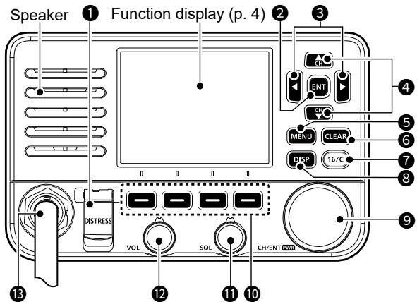
DISTRESS KEY [DISTRESS]
Hold down for 3 seconds to transmit a Distress call. (p. 21)
2 ENTER KEY [ENT]
Push to set the entered data, selected item, and so on.
LEFT/RIGHT KEYS [] / []
- Push to scroll the Software Key functions. (pp. 6~7)
- Push to select a character or number in the entry mode. (pp. 8, 14, 19~20)
4 UP/DOWN KEYS [▲]/[▼]
- Push to select an operating channel, Menu items, Menu settings, and so on. (p. 10)
- Push to select a character or number in the entry mode. (pp. 14, 19~20)
5 MENU KEY [MENU]
Push to display or close the Menu screen.
CLEAR KEY [CLEAR]
Push to cancel the entered data or to return to the previous screen.
CHANNEL 16/CALL CHANNEL KEY [16/C]
- Push to select Channel 16. (p. 10)
- Hold down for 1 second to select the Call channel. (p. 10)
DISPLAY KEY [DISP]
- Push to switch the main screen between the INFO, the Plotter, and the Highway screens.
- In the main screen, hold down for 1 second to quickly toggle the display mode (Day mode or Night mode).
CHANNEL/ENTER/POWER DIAL [CH/ENT]/[PWR]
- Hold down for 1 second to turn the transceiver ON or OFF.
- Rotate to select the operating channels, Menu items, Menu settings, and so on.
- Push to set the entered data, selected item, and so on.
SOFTWARE KEYS (pp. 6~7)
Scroll the key functions pushing [<] or [▶], then push either of the 4 Software Keys to select the function displayed at the bottom of the display.
SQUELCH DIAL [SQL] (p. 12)
Rotate to adjust the squelch level.
12 VOLUME DIAL [VOL] (p. 12)
Rotate to adjust the volume level.
MICROPHONE CONNECTOR
CAUTION:
- Be sure that the microphone connector is tightened completely (rotate clockwise) to maintain the transceiver's waterproof protection.
- When a microphone is not connected to the front panel, attach the supplied microphone connector cap to the rear panel.
2 PANEL DESCRIPTION
■ Speaker Microphone
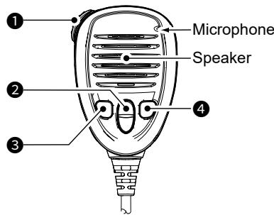
PTT SWITCH [PTT] (p. 13)
Hold down to transmit, release to receive.
UP/DOWN KEYS [▲]/[▼] (p. 17)
Push to select the Favorite channels, change scanning direction or manually resume a scan.
① When the "FAV on MIC" item is set to "OFF," you can select all channels. (p. 86)
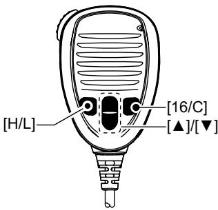
③ TRANSMIT POWER KEY [H/L]
- Push to set the power level to high or low.
① Some channels are set to only low power.
- You can turn the Microphone Lock function ON or OFF by turning the transceiver ON while holding down this key. (p. 15)
4 CHANNEL 16/CALL CHANNEL KEY [16/C] (p. 10)
-
Push to select Channel 16.
-
Hold down for 1 second to select the Call channel.
① The "CALL" icon is displayed.
Function Display (INFO screen)
① When you switch the main screen between the INFO, the Plotter, and the Highway screens, push [DISP].
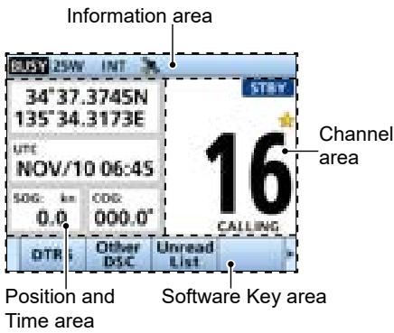
Position and Time area
POSITION AREA
The current position is displayed when valid GPS data is received, or you manually enter your position.
| Indicator | Description |
| NO POSITION | Displayed when a GPS antenna is not connected or your position has not been manually entered. |
| ?? | Blinks every 2 seconds instead of your position when: • The GPS position is invalid. • 4 hours have passed since you manually entered your position. ① After 23.5 hours have passed, “NO POSITION” will be displayed. |
TIME AREA
The current time is displayed when valid GPS data is received, or manually enter the time.
| Indicator | Description |
| NO TIME | Displayed when a GPS antenna is not connected or the time has not been manually entered. |
| Local | Displayed when the offset time is set. |
| Manual | Displayed when the time was manually entered. |
| UTC | Displayed when the RMC, GGA, GLL, or GNS sentences are received from the built-in GPS receiver, an external NMEA 0183, or external NMEA 2000 sentence source. |
| ?? | Blinks every 2 seconds instead of the time when: • The GPS current time is invalid. • 4 hours have passed since you manually entered the time. ① After 23.5 hours have passed, “NO TIME” will be displayed. |
- Position and Time area also displays your vessel's SOG (Speed Over Ground) and COG (Course Over Ground).
① SOG or COG may not be displayed, depending on the NMEA 0183 or the NMEA 2000 data.
2 PANEL DESCRIPTION
Information area
The MMSI code* and the following indicators are displayed in the Information area.
*ATIS code is displayed if only the ATIS code is entered in NLD and FRG version.
| Indicator | Description |
| BUSY | Displayed when receiving a signal or when the squelch is open. |
| TX | Displayed while transmitting. |
| 25W | Displayed when high power is selected. |
| 1W | Displayed when low power is selected. |
| USA, INT, CAN, WX, ATIS, DSC | Displays the selected channel group, INT (International), USA, CAN (Canada), WX (Weather channel), ATIS or DSC. ① When the WX-A Alert is set to ON, “” is displayed. (For only the USA version) |
| Displayed when the transceiver receives valid position and time data. Blinks when invalid GPS data is being received. | |
| Displayed when the WLAN function is activated. In the Client mode, displays the WLAN signal strength while connected to a wireless network. | |
| Displayed when the Auto Foghorn function is activated. (p. 75) | |
| Displayed when the battery voltage is less than 11 V. | |
| Displayed while accessing to the mobile device using the RS-M500. ① The number indicates the number of connected mobile devices. | |
| Displayed when there is a target in the CPA/TCPA alarm function. | |
| • Displayed when there are unread DSC messages. • Blinks when a DSC message is received. | |
| Displayed when the “CH Auto Switch” in DSC Settings is set to an option except “Accept after 10 sec.”. |
Channel area
The selected operating channel number, channel name, and the following indicators are displayed in the Channel area.
| Indicator | Description |
| ★ | Displayed when a Favorite channel is selected. |
| CALL | Displayed when the Call channel is selected by holding down [16/C] for 1 second. |
| DUP | Displayed when a Duplex channel is selected. |
| STBY | Displayed while in the Standby mode. |
| RT | Displayed while in the Radio Telephone (RT) mode. ① Returns to the Standby mode if no operation occurs during the preset period of time. |
| DSC | Displayed after making or receiving a DSC call. ① If the transceiver is in the Multiple Task mode, the number of DSC tasks is displayed by the indicator. |
| RXO | Displayed when in the RX Hailer mode. (p. 73) |
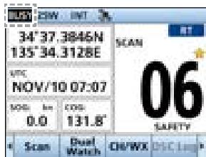
| SCAN 16* | Displayed during a Priority scan. (p. 16) |
| SCAN* | Displayed during a Normal scan. (p. 16) |
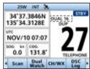
| DUAL 16* | Displayed during Dualwatch. (p. 18) |
| TRI 16* | Displayed during Tri-watch. (p. 18) |
| LOC | Displayed when the Attenuator function is turned ON. (For only the USA version.) |
- Not usable in NLD version
■ Software Keys
Various often-used functions are assigned to the Software Keys for easy access. The functions' icons are displayed above the Software Keys, as shown below.
Selecting a Software Key function
Push [<] or [▶] to slide through the selectable functions that are assigned to the Software Keys.
Push the Software Key under the function's icon to select the function.
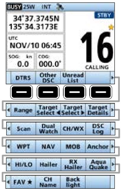
NOTE: The displayed icons or their order may differ, depending on the transceiver version or the presetting. When the MMSI code is not set, the Software Keys for the DSC function are not displayed.
Software Key functions
Compose Distress [DTRS] (p. 22)
Push to display the "Compose Distress" screen to select the nature of distress, then to make a call.
NEVER MAKE A DISTRESS CALL IF YOUR SHIP OR A PERSON IS NOT IN AN EMERGENCY. A DISTRESS CALL SHOULD BE MADE ONLY WHEN IMMEDIATE HELP IS NEEDED.
Other DSC (p. 25)
Push to compose an Individual call, Group call, All Ships call or a Test call, and so on.
Unread List
Push to enter the Unread List.
① Displayed only when "Single" is selected in the DSC procedure menu. (p. 47)
Task List (p. 44)
(For only the USA version)
Push to enter the Task List.
① Displayed only when "Multiple" is selected in the DSC procedure menu. (p. 47)
Range (p. 53)
Push to the select the plotter display range on the Plotter screen.
① Displayed only on the plotter screen.
Target Select / Target Select (p. 52)
Push to select an AIS target, waypoint, or MOB.
① Displayed only on the plotter screen.
Target Details (p. 57)
Push to display the details on the selected target.
① Displayed only on the plotter screen.
Scan (p. 17)
(Except for the NLD version)
Push to start or stop a Normal or Priority scan.
2 PANEL DESCRIPTION
Software Key functions
DualWatch/Tri-Watch (p. 18)
(Except for the NLD version)
Push to start or stop the Dualwatch or Triwatch.
Channel/Weather channel [CH/WX] (p. 11)
Push to select regular channels or Weather channels.
The Weather channel is for only the USA versions. [CH] is displayed for other versions.
① While the Call channel or Channel 16 is displayed, push this key to return to the regular channel mode.
DSC Log (p. 43)
Push to display the received call log or distress message log.
Waypoint [WPT] (p. 63)
Push to save your position information to the transceiver.
Navigation [NAV]/[Stop NAV] (p. 67)
Push to start navigation.
While navigating, push to stop navigation.
Man Overboard
[MOB]/[Stop MOB] (p. 65)
Push to enter the Man Overboard (MOB) mode.
While in the Man Overboard (MOB) mode, push to stop the Man Overboard (MOB) mode.
Anchor
[Anchor]/[Stop Anchor] (p. 66)
Push to start or stop the Anchor watch function.
High/Low [HI/LO] (p. 3)
Push to set the output power level to high or low.
① Some channels are set to only low power.
Voice Scrambler [Voice SBL] (p. 76)
Push to set the Voice Scrambler function.
① This function is displayed only when the voice scrambler unit is installed.
Hailer (p. 74)
Push to display the Hailer screen.
① To use this function, the external hailer speaker must be connected to the transceiver.
RX Hailer (p. 73)
Push to display the RX Hailer popup screen.
① To use this function, the external hailer speaker must be connected to the transceiver.
LO/DX (p. 86)
(For only the USA version)
Push to turn the Attenuator function ON or OFF.
① The "LOC" icon is displayed when the Attenuator function is ON.
AquaQuake (p. 14)
Hold down to turn ON the AquaQuake function to clear water from the speaker grill.
Favorite [FAV★] (p. 17)
Push to set or clear the displayed channel as a Favorite channel.
CH Name (p. 14)
Push to edit the name of the displayed channel.
Backlight (p. 12)
Push to display the Backlight popup screen.
In the Backlight popup screen, you can set the backlight level, and the display mode.
For only the European version:
When you turn ON the transceiver, "Model" screen is displayed depending on the setting. Select the country where you operate the transceiver.
① If no country is selected, "General" is automatically selected.
■ Entering the MMSI code
The Maritime Mobile Service Identity (MMSI: DSC self ID) code consists of 9 digits. You can only enter the code when turning ON the transceiver for the first time.
This initial code can be entered only once.
If your MMSI code has already been entered, doing the steps below is not necessary.
- Hold down [PWR] to turn ON the transceiver.
- Three short beeps sound, and "Push [ENT] to Register your MMSI" is displayed.
- Push [ENT] to start entering the MMSI code.
- The "MMSI INPUT" screen is displayed.
Push [CLEAR] twice to skip the entry. If you skip the entry, you cannot make a DSC call. To enter the code after skipping, turn OFF the power, and then turn it ON again. - Enter the MMSI code.
TIP:
- Select a number using [] and [] .
- Push [ENT] or [CH/ENT] to enter the selected number.
- Select “ ” or “ ” on the screen, or rotate [CH/ENT] to move the cursor.
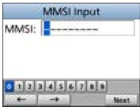
- Repeat step 3 to enter all 9 digits.
-
Select Next and push [ENT] or [CH/ENT] to set the entered code.
-
The "MMSI Confirmation" screen is displayed.
-
Enter your MMSI code again to confirm.
-
Push Finish to set the entered code.
-
When your MMSI code is successfully entered, "MMSI registered successfully." is briefly displayed, and then enters the operating screen.
① Your MMSI code is also displayed on the opening screen.
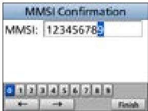
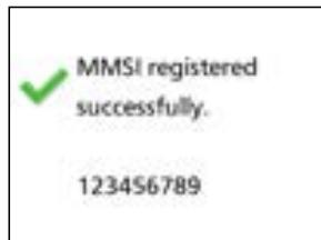
3 PREPARATIONS
■ Entering the ATIS ID (For NLD and FRG versions)
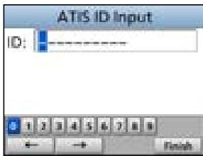
The Automatic Transmitter Identification System (ATIS) ID consists of 10 digits. You can enter the ID in the "ATIS ID Input" item on the Menu screen.
This ID entering can be done only once.
If your ATIS ID has already been entered, doing the steps below is not necessary.
- Push [MENU].
- The Menu screen is displayed.
- Push [] or [] , or rotate [DIAL] to select "ATIS ID Input," then push [ENT] to start entering.
- The "ATIS ID Input" screen is displayed.
- Enter your ATIS ID.
TIP:
- Select a number using [] and [] .
- Push [ENT] or [CH/ENT] to enter the selected number.
-
Select "←" or "→" on the screen, or rotate [CH/ENT] to move the cursor.
-
Repeat step 3 to enter all 10 digits.
-
Push Finish to set the entered ID.
-
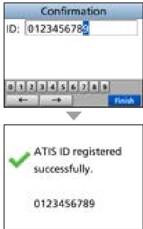
The "Confirmation" screen is displayed.
-
Enter your ATIS ID again to confirm.
-
Push Finish to set the entered ID.
-
When your ATIS ID is successfully entered, the screen displays "ATIS ID registered successfully," and then enters the operating screen.
① You can check the ATIS ID in "Radio Info" on the Menu screen.
Selecting a channel
Regular Channel
You can select a channel by pushing [] or [] .
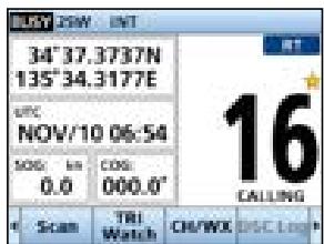
Channel 16
Channel 16 is the distress and safety channel. It is used to establish the initial contact with a station, and for emergency communications. Channel 16 is monitored during both Dualwatch and Tri-watch. While in the standby mode, you must monitor Channel 16.
- Push [16/C] to select Channel 16.
① To return to the previously selected channel, push [▲] or [▶] to display CH/WX or CH, and then push the Software Key below CH/WX or CH.
Call channel
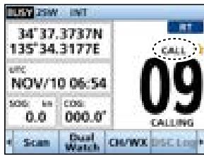
Each Channel Group has separate leisure-use Call channels. The Call channel is scanned during Tri-watch. The Call channels can be selected and used to store your most often used channels in each Channel Group, for quick recall. See page 13 for details on setting the Call channel.
-
Hold down [16/C] for 1 second to select the Call channel.
-
The Call channel number and "CALL" are displayed.
① To return to the previously selected channel, push [←] or [▶] to display CH/WX or CH, and then push the Software Key below CH/WX or CH.
Selecting a Channel Group
Channel Groups are preset into your transceiver. You can select a Channel Group for USA, International, Canadian, DSC, and ATIS depending on the transceiver version.
- Open the "Channel Group" screen.
[MENU] > Settings > Radio > Channel Group
- Push [] or [] , or rotate [CH/ENT] to select a Channel Group, and then push [ENT], or [CH/ENT].
- Push [MENU] to exit the Menu screen.
- The selected Channel Group's icon is displayed on the operating screen.
| Version | Preset Channel Group | ||||
| USA | INT | CAN | DSC | ATIS | |
| USA | ✓ | ✓ | ✓ | ||
| UK | ✓ | ✓ | |||
| European | ✓ | ||||
| NLD | ✓ | ✓ | |||
| FRG | ✓ | ✓ | ✓ | ||
4 BASIC OPERATIONS
■ Weather channels and Weather Alert (For only the USA versions)
The USA version transceiver has 10 preset Weather channels.
The transceivers are capable* of monitoring broadcasts from the National Oceanographic and Atmospheric Administration (NOAA). The transceiver automatically detects a Weather alert tone on the selected weather channel, or while scanning.
*When used within range of the broadcasts.
Selecting a Weather channel
-
Push [CH/WX].
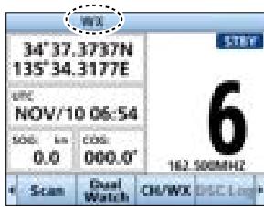
-
"WX" is displayed on the operating screen instead of the Channel Group.
-
Push [] or [] , or rotate [CH/ENT] to select a Weather channel.
The Weather channel list
| WX channel | Frequency (MHz) | WX channel | Frequency (MHz) |
| 1 | 162.550 | 6 | 162.500 |
| 2 | 162.400 | 7 | 162.525 |
| 3 | 162.475 | 8 | 161.650 |
| 4 | 162.425 | 9 | 161.775 |
| 5 | 162.450 | 10 | 163.275 |
Setting the Weather Alert
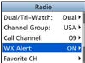
To receive the weather alert, set the WX Alert to "ON with Scan," or "ON."
- Open the "Weather Alert" screen.
[MENU] > Settings > Radio > WX Alert
-
Select "ON with Scan," or "ON."
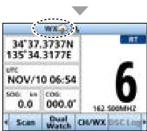
-
" " is displayed next to the weather channel icon.
① "WX" blinks until you push a key after detecting an alert.
Adjusting the volume/squelch/backlight/display mode
Adjusting the volume level
- Rotate [VOL] to adjust the audio volume level.
Adjusting the squelch level
Squelch enables the audio to be heard only while receiving a signal that is stronger than the set level. A higher level blocks weak signals, so that you can receive only stronger signals. A lower level enables you to hear weak signals.
- Rotate [SQL] to adjust the squelch level.
Adjusting the backlight and the display mode
The Function display and keys can be backlit for better visibility under low light conditions. And, you can set the display mode to Day mode or Night mode.
The Day mode is for the daytime operation, and the screen items are in full color.
The Night mode is for the nighttime operation, and the screen items are in black and red.
① In the main screen, hold down [DISP] for 1 second to quickly toggle the display mode (Day mode or Night mode), without opening the "Backlight" screen.
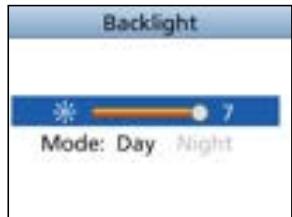
- Open the "Backlight" screen.
[MENU] > Settings > Configuration > Backlight
① You can also push Backlight to open the "Backlight" popup screen.
-
Push [<] or [▶] or rotate [CH/ENT] to adjust the backlight level.
-
The backlight level is set, and the transceiver returns to the previous screen.
① The backlight level is adjustable in 7 levels and "OFF." "OFF" is selectable only for the Day mode.
- Push [] , then push [] or [] or rotate [CH/ENT] to select "Day" or "Night."
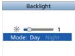
- Push [ENT] or [CH/ENT] to exit the Menu screen.
4 BASIC OPERATIONS
Setting the Call channel
By default, a Call channel is set in each Channel Group.
You can set your most often-used channel as your Call channel in each Channel Group for quick recall.
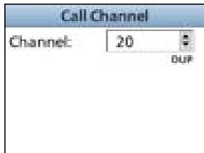
- Open the "Call Channel" screen.
[MENU] > Settings > Radio > Call Channel
- Push [ ] or [ ] , or rotate [CH/ENT] to select the channel.
- Push [ENT] or [CH/ENT] to set the selected channel as the Call channel.
- Push [MENU] to exit the Menu screen.
Receiving and transmitting
CAUTION: DO NOT transmit without an antenna.
- Push [] or [] , or rotate [CH/ENT] to select a channel to call on.
- The channel number and name are briefly displayed.
① is displayed while receiving a signal. - Hold down [PTT] and speak into the microphone at your normal voice level.
- Tx is displayed while transmitting.
- Release [PTT] to receive.
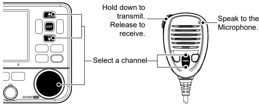
TIP: To maximize the readability of your transmitted signal, pause for a second after holding down [PTT] and hold the microphone 5 to 10cm (2 to 4 inches) from your mouth, and then speak at your normal voice level.
NOTE: The Time-out Timer function cuts OFF transmission after 5 minutes of continuously transmitting, to prevent prolonged transmission.
AquaQuake Water Draining function
Water in the speaker grill may muffle the sound coming from the speaker. The AquaQuake Water Draining function removes water from the speaker grill by vibrating the speaker cone.
CAUTION: DO NOT use the AquaQuake Water Draining function when an external speaker is connected.
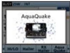
- Push [▲] or [▶] to display AquaQuake.
-
Hold down AquaQuake to turn ON the function.
-
A low frequency vibration beep sounds to drain the water, regardless of the volume level setting.
This function is activated for a maximum of 10 seconds, even if you continue to hold down AquaQuake.
- Release the key to turn OFF the function.
■ Editing a channel name
You can edit the name of each operating channel and weather channel, using numbers, uppercase letters, symbols, and a space. This enables easy recognition of the channels or stations. All VHF marine channels are set with default names.
- Push [▲] or [▼], or rotate [CH/ENT] to select the channel to edit.
- Push [<] or [>] to display CH Name.
① You cannot edit a channel name during Dualwatch, Tri-watch, or a scan.
-
Push CHName.
-
The "Channel Name" screen is displayed.
-
Edit the channel name.
- Select Finish, and then push [ENT] or [CH/ENT] to save the edited name and return to the operating screen.
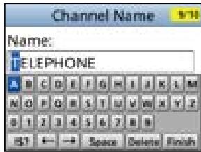
TIP:
- Select to enter numbers and letters, and to enter symbols.
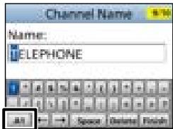
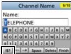
- Select a number, character, or space using [], [], [], and [] .
- Push [ENT] or [CH/ENT] to enter the selected number or character.
- Select “←” or “→” on the screen or rotate [CH/ENT] to move the cursor, or to select the entered character.
4 BASIC OPERATIONS
Microphone Lock function
The Lock function electronically locks all keys on the microphone except [PTT] to prevent accidental channel changes or functions access.
- Hold down [PWR] for 1 second to turn OFF the transceiver.
- While holding down [H/L] on the microphone, hold down [PWR] for 1 second to turn the Lock function ON or OFF.
■ Scan types
You can find ongoing communication by scanning the Favorite channels. Scan is for all the transceiver versions except the NLD version.
Before starting a scan :
- Set the channels that you want to scan as Favorite channels. (p. 17)
① Only the Favorite channels are scanned.
- Set the scan type to "Priority Scan" or "Normal Scan" on the "Radio Settings" screen. (p. 85)
[MENU] > Settings > Radio > Scan Type
Normal Scan
Sequentially searches through all Favorite channels. Channel 16 is not scanned unless it is set as a Favorite channel.
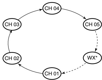
*For the USA version, when the Weather Alert function is ON, the previously selected Weather channel is also scanned.
Priority Scan
Sequentially searches through all Favorite channels, while also periodically checking Channel 16.
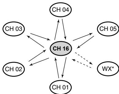
*For the USA version, when the Weather Alert function is ON, the previously selected Weather channel is also scanned.
When a signal is received:
On Channel 16:
On a channel other than Channel 16:
The scan pauses until the signal disappears. The scan becomes Dualwatch until the signal disappears.
5 SCAN OPERATION
Setting Favorite channels
You can quickly recall often-used channels by setting them as Favorite channels. You can set Favorite channels in each Channel Group.
- Select a Channel Group on the Menu screen. (p. 10)
[MENU] > Settings > Radio > Channel Group
- Push [ ] or [ ] , or rotate [CH/ENT] to select the channel.
- Push [<] or [> ] to display FAV★.
-
Push FAV★.
-
The selected channel is set as a Favorite channel, and " " is displayed.
① To cancel the setting, push FAV again.
TIP: You can set all channels as Favorite channels, clear all settings, or reset to the defaults. By default, some channels are preset as Favorite channels. The preset channels differ, depending on the transceiver version.
Starting a scan (Except for the NLD version)
Example: Starting a Normal Scan.
- Select a Channel Group on the Menu screen. (p. 10)
[MENU] > Settings > Radio > Channel Group
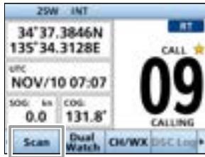
- Push [<] or [> to display Scan
- Push Scan
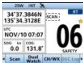
The scan starts.
- "SCAN" is displayed during a Normal Scan, and "SCAN 16" is displayed during a Priority Scan.
- "SCAN" and "Mystic" are displayed when a signal is received.
① When a signal is received, the scan pauses until it disappears, or resumes after 5 seconds, depending on the Scan Timer setting in "Radio Settings."
① A beep sounds and "16" blinks when a signal is received on Channel 16 during a Priority scan.
- To stop the scan, push Scan
TIP: To properly receive signals, be sure to adjust the squelch to a suitable level.
DUALWATCH/TRI-WATCH (Except for the NLD version)
Description
Dualwatch and Tri-monitor are convenient to periodically check Channel 16 while you are operating on another channel.
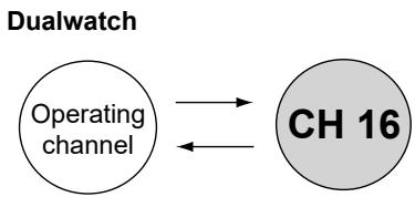
Periodically checks Channel 16 while operating on another channel.
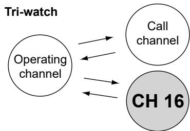
Periodically checks Channel 16 and the Call channel while operating on another channel.
When a signal is received:
On Channel 16: Dualwatch/Tri-watch pauses on Channel 16 until the signal disappears.
On the Call channel: Tri-watch switches to Dualwatch until the signal on the Call channel disappears.
Operation
- Select Dualwatch or Tri-watch on the Menu screen.
[MENU] > Settings > Radio > Dual/Tri-Watch
- Push [] or [] , or rotate [CH/ENT] to select a channel.
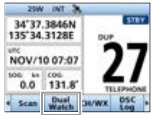
- Push [<] or [▶] to display Dual Watch or Tri Watch.
-
Push Dual Watch or Tri Watch.
-
Dualwatch or Tri-watch starts.
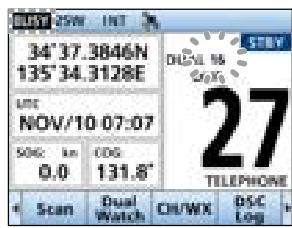
-DUAL 16" is displayed for Dualwatch, or "TRI 16" is displayed for Tri-watch.
① “是” is displayed when a signal is received.
① A beep tone sounds and "16" starts to blink when a signal is received on Channel 16.
- To cancel Dualwatch or Tri-watch, push Dual Watch or TriWatch again.
DSC address ID
Entering an Individual or Group ID
You can enter a total of 75 Individual IDs and 25 Group IDs, and assign names to them of up to 10 characters.
- Open the "Individual ID" or "Group ID" screen.
[MENU] > Settings > DSC > Individual ID
[MENU] > Settings > DSC > Group ID
-
"No ID" is displayed if no ID is entered.
-
Push Add
- The ID entry screen is displayed.
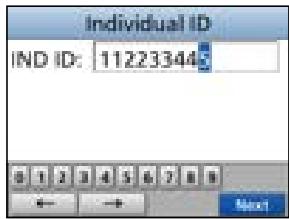
- Enter an Individual or Group ID.
TIP:
- Select a number using [] and [] .
- Push [ENT] or [CH/ENT] to set the selected number.
- Select "←" or "→" on the screen, or rotate [CH/ENT] to move the cursor.
NOTE:
- For a Group ID, the first digit is fixed as "0."
-
For any coast station ID, the first two digits are fixed as "0."
-
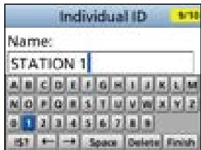
Push Next to start entering the ID's name.
TIP:
- Select A1 to enter numbers and letters, and B1 to enter symbols.
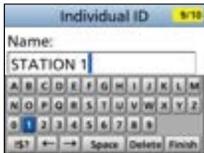

- Select a number, character, or space using [], [], [], and [] .
- Push [ENT] or [CH/ENT] to enter the selected number or character.
- Select "←" or "→" on the screen to move the cursor, or to select the entered character.
-
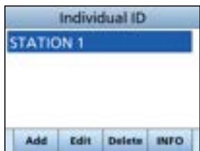
After entering, select Finish, and then push [ENT] or [CH/ENT] to save, and return to the previous screen.
-
The entered name is displayed.
Deleting an entered ID
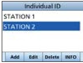
(Example: Deleting an Individual ID: STATION 2)
- Open the "Individual ID" screen.
[MENU] > Settings > DSC > Individual ID
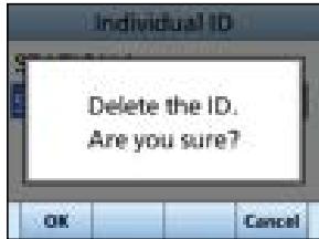
- Select "STATION 2," and then push Delete
"Delete the ID. Are You Sure?" is displayed.
- Push OK to delete.
① Push Cancel to cancel the deletion.
- The selected ID is deleted, and then returns to the previous screen.
TIP: You can edit an ID and its name by pushing Edit in step 2.
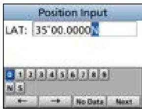
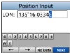
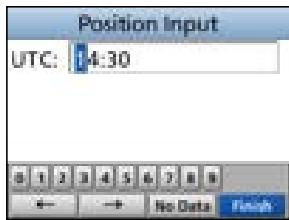
■ Entering the position and time
A Distress call should include the vessel's position, date, and time. If no GPS data is received, manually enter the position and Universal Time Coordinated (UTC) time.
NOTE:
- The manual entry is disabled while valid GPS data is received.
-
The manually entered position and time is valid only for 23.5 hours, or until turning OFF the transceiver.
-
Open the "Position Input" screen.
[MENU] > Settings > DSC > Position Input
- Enter the latitude.
TIP:
- Select a number or a compass direction using [] , [] , [] , and [] .
- Select “ ” or “ ” on the screen, or rotate [CH/ENT] to move the cursor.
-
Select Next and then push [ENT] or [CH/ENT] to save the selected number.
-
Enter the longitude and the UTC time.
① See the TIP in step 2 to enter.
-
After entering, select Finish, and then push [ENT] or [CH/ENT] to save, and return to the previous screen.
-
The "DSC" screen is displayed.
7 DIGITAL SELECTIVE CALLING (DSC)
Sending DSC calls (Distress)
A Distress call should be sent if, in the opinion of the captain, the ship or a person is in distress and requires immediate assistance.
NEVER MAKE A DISTRESS CALL IF YOUR SHIP OR A PERSON IS NOT IN AN EMERGENCY. A DISTRESS CALL SHOULD BE MADE ONLY WHEN IMMEDIATE HELP IS NEEDED.
Simple call
- Confirm that no Distress call is being received.
-
While lifting up the key cover, hold down [DISTRESS] for 3 seconds until you hear 3 short countdown beeps and a long beep sound.
-
The backlight blinks.
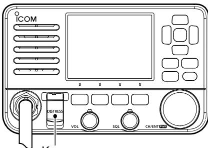
Key cover
-
After sending, wait for an Acknowledgment call.
-
"Waiting for ACK" is displayed.
-
The Distress call is automatically sent every 3.5 to 4.5 minutes, until an Acknowledgment is received, or a Distress Cancel call is sent.
-
When you receive an Acknowledgment, an alarm sounds. Push Alarm OFF to turn OFF the alarm.
-
Channel 16 is automatically selected.
-
Push Close Window
- Hold down [PTT], and then explain your situation.
-
After you have finished your conversation, push STBY.
-
"Terminate the procedure. Are you sure?" is displayed.
-
Push OK to return to the operating screen.
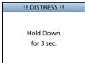
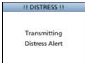
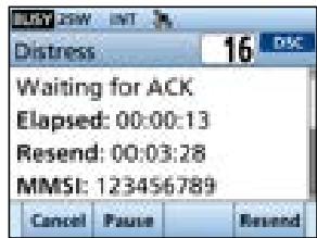
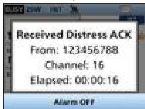
TIP: A default Distress alert contains:
- Nature of distress: Undesignated distress
- Position information: The latest GPS, or manually input position, that is held for 23.5 hours, or until you turn OFF the transceiver.
Regular call
Select the nature of the Distress call to include in the Regular Distress call.
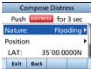
-
Push DTRS.
-
The "Compose Distress" screen is displayed.
-
Push [ENT] or [CH/ENT] to enter the Nature selection mode.
-
Select the nature of the Distress, and then push [ENT] or [CH/ENT]. (Example: Flooding)
-
The setting is saved and returns to the previous screen.
① If no valid GPS data is being received, select "Position," and then enter the latitude, longitude, and UTC.
See "Entering the position and time" on page 20 for details.
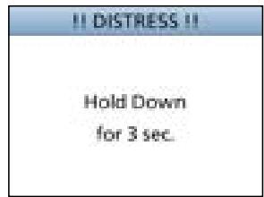
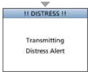
-
While lifting up the key cover, hold down [DISTRESS] (the red button) for 3 seconds until you hear 3 short countdown beeps and a long beep sound.
-
The backlight blinks.
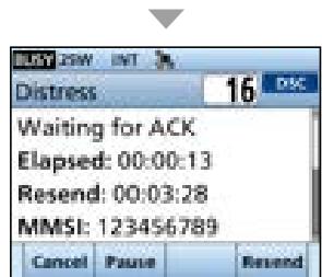
-
After sending, wait for an Acknowledgment.
-
"Waiting for ACK" is displayed.
① The Distress call is automatically sent every 3.5 to 4.5 minutes, until an Acknowledgment is received, or a Distress Cancel call is sent. (p. 23)
-
When you receive an Acknowledgment, an alarm sounds. Push Alarm OFF to turn OFF the alarm.
-
Channel 16 is automatically selected.
-
Hold down [PTT] to communicate.
- After you have finished your conversation, push STBY. Terminate the procedure. Are you sure?" is displayed.
- Push OK to return to the operating screen.
TIP: You can also send a Regular call by selecting the "Distress" item on the Menu screen.
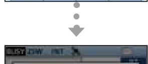
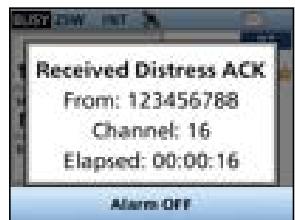
7 DIGITAL SELECTIVE CALLING (DSC)
Distress Cancel call
If you have accidentally made a Distress call, or made an incorrect Distress call, send a Distress Cancel call to cancel the call as soon as possible while waiting for an Acknowledgment. Be sure to report the purpose of the cancellation.
-
While waiting for an Acknowledgment, push Cancel.
-
The screen on the right is displayed.
-
Push OK
-
The Distress Cancel call is sent.
- Channel 16 is automatically selected.
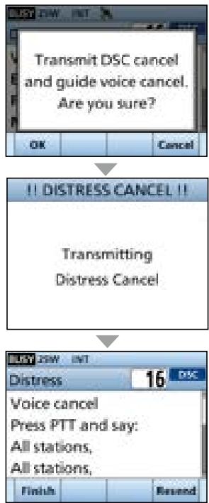
- Hold down [PTT] to report the purpose of the cancellation.
① You can display the wording of the cancellation by pushing [] .
- After communicating, push Finish
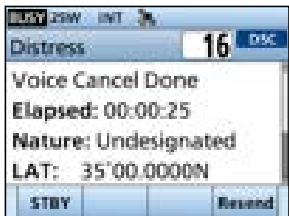
① The screen on the right is displayed.
-
Push STBY to finish the Distress Cancel call.
-
"Terminate the procedure. Are you sure?" is displayed.
-
Push OK to return to the operating screen.
Distress call Software Key description
While waiting for an Acknowledgment:
Cancel: Cancels the Distress call and enables you to send a Cancel call.
Resend: Enables you to resend the Distress call by holding down [DISTRESS] again.
Pause: Pauses the countdown to resend the next Distress call.
After receiving an Acknowledgment:
STBY: Closes the Distress operation, and returns to the operating screen.
History : Displays the “Distress History.”
Sending a Distress Relay acknowledgment (For only the USA version)
You can send the Distress Relay acknowledgment only when a Distress Relay call is received.
- When a Distress Relay call is received:
An alarm sounds.
- The screen on the right is displayed.
- Push any Alarm OFF to turn OFF the alarm.
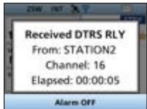
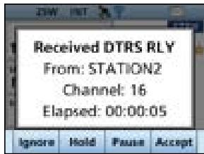
- Push Accept
The received information is displayed.
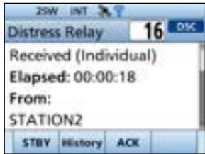
-
Push ACK
-
The call contents screen is displayed.
① Rotate [CH/ENT] to view the call contents.
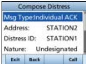
- Push Call to send the Distress Relay acknowledgment.
After sending, "Distress Relay ACK" screen is displayed.
-
Hold down [PTT] to communicate.
-
After you have finished your conversation, push STBY.
-
"Terminate the procedure. Are you sure?" is displayed.
-
Push OK to return to the operating screen.
7 DIGITAL SELECTIVE CALLING (DSC)
Sending DSC calls (other)
NOTE: To ensure proper DSC operation, be sure to correctly adjust the "CH 70 SQL Level" item on the Menu screen. (p. 47)
Sending an Individual call
An Individual call enables you to send a DSC signal to only a specific station. You can communicate after receiving the Acknowledgment "Able to comply."
NOTE: You can also compose an Individual call to an AIS target on the Plotter screen or the AIS list. (pp. 51, 54)
-
Push Other DSC.
-
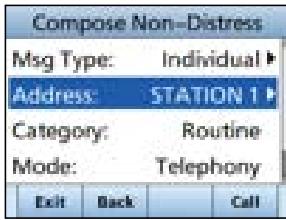
The "Compose Non-Distress" screen is displayed.
① You can also display the "Compose Non-Distress" screen by selecting the "Other DSC" item on the Menu screen. -
Select "Msg Type," and then push [ENT] or [CH/ENT].
-
Select "Individual," and then push [ENT] or [CH/ENT].
-
Returns to the "Compose Non-Distress" screen.
-
Select "Address," and then push [ENT] or [CH/ENT].
-
Select the station to send an Individual call to, and then push [ENT] or [CH/ENT].
-
Returns to the "Compose Non-Distress" screen.
① You can also select "Manual Input" to manually enter the target station ID.
-
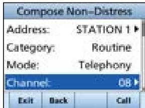
Select "Channel," and then push [ENT] or [CH/ENT].
-
Select a channel to assign, and then push [ENT] or [CH/ENT].
① The assigned channels are preset by default.
-
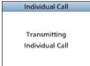
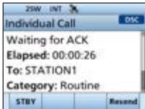
Push Call to send the Individual call.
-
"Transmitting Individual Call" is displayed, and then "Waiting for ACK" is displayed.
① If Channel 70 is busy, the transceiver stands by until the channel becomes clear.
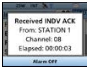
- When you receive an Acknowledgment "Able to comply":
An alarm sounds.
- The screen on the right is displayed.
-
Push Alarm OFF to turn OFF the alarm.
-
The channel assigned in step 7 is automatically selected.
If the called station cannot use the channel that you assigned, a different channel is selected by the other station. -
Push Close Window.
-
Hold down [PTT] to communicate.
TIP: If you received an Acknowledgment "Unable to comply":
- Push Alarm OFF to turn OFF the alarm, and then push Close Window. The Acknowledge information is displayed.
- Push STBY, and then OK to return to the operating screen.
Sending an Individual Acknowledgment
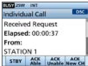
When you have received an Individual call (p. 38), send an Acknowledgment to the calling station. When the Auto Ack is set to "Manual," you can select an appropriate acknowledgment type.
- While an Individual call is being received, push Alarm OFF to turn OFF the alarm.
The received call's information is displayed. - Push [Accept].
-
The Acknowledgment category screen is displayed.
① If you want to send an Acknowledgment "Able to comply" right away, push Able.
① If you cannot communicate, and want to return to the operating screen, push Ignore. -
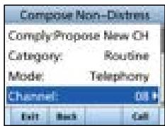
Push ACK Able, ACK Unable, or ACK New CH to select the Acknowledgment type.
ACK Able:
(Able to
Comply)
ACK Unable:
(Unable to
Comply):
ACK New CH:
(Propose
New CH)
Sends an Acknowledgment without any changes.
Sends an Acknowledgment but cannot communicate.
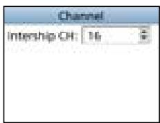
Sends an Acknowledgment. You can specify the Voice Communication channel.
(Example: Channel 16)
- Push Call to send the Acknowledgment.
7 DIGITAL SELECTIVE CALLING (DSC)
Sending an All Ships call
All Ships that have DSC transceiver use Channel 70 as their listening channel. When you want to announce a message to these ships, if they are within range, use the All Ships call.
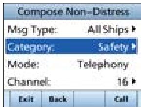
1. Push Other DSC.
-
The "Compose Non-Distress" screen is displayed.
① You can also display the "Compose Non-Distress" screen by selecting the "Other DSC" item on the Menu screen. -
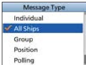
Select "Msg Type," and then push [ENT] or [CH/ENT].
- The "Message Type" screen is displayed.
- Select "All Ships," and then push [ENT] or [CH/ENT].
- The All Ships call is selected, and returns to the "Compose Non-Distress" screen.
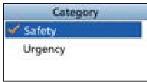
- Select "Category," and then push [ENT] or [CH/ENT].
- The "Category" screen is displayed.
- Select a category of the call, and the push [ENT] or [CH/ENT].
- The category is set, and returns to the "Compose Non-Distress" screen.
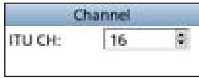
- Select "Channel," and then push [ENT] or [CH/ENT].
- Select the channel to assign, and then push [ENT] or [CH/ENT].
① The assigned channels are preset by default.
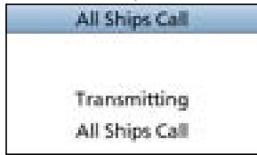
- Push Call to send the All Ships call.
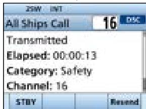
- "Transmitting All Ships Call" is displayed, and then the assigned channel is automatically selected.
① If Channel 70 is busy, the transceiver stands by until the channel becomes clear. -
Hold down [PTT] to communicate.
-
Push STBY to finish the All Ships call.
-
"Terminate the procedure. Are you sure?" is displayed.
- Push OK to return to the operating screen.
- Returns to the operating screen.
Sending a Group call
A Group call enables you to send a DSC call to only a specific group.
① You can send a Group call to a pre-entered group address, or manually enter the address before sending. (p. 19)
-
Push Other DSC.
-
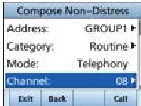
The "Compose Non-Distress" screen is displayed.
① You can also display the "Compose Non-Distress" screen by selecting the "Other DSC" item on the Menu screen.
-
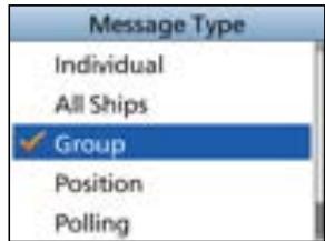
Select "Msg Type," and then push [ENT] or [CH/ENT].
-
The "Message Type" screen is displayed.
-
Select "Group," and then push [ENT] or [CH/ENT].
-
The Group call is selected, and returns to the "Compose Non-Distress" screen.
-
Select "Address," and then push [ENT] or [CH/ENT].
-
The "Address" screen is displayed.
-
Select the group to send a Group call, and then push [ENT] or [CH/ENT].
① You can also select "Manual Input" to manually enter the target group.
-
Select "Channel," and then push [ENT].or [CH/ENT].
-
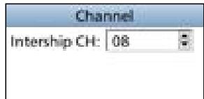
Select the channel to assign, and then push [ENT].
① The assigned channels are preset by default.
-
Push Call to send the Group call.
-
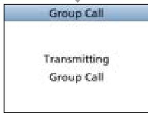
"Transmitting Group Call" is displayed, and then the assigned channel is automatically selected.
① If Channel 70 is busy, the transceiver stands by until the channel becomes clear.
- Hold down [PTT] to communicate.

7 DIGITAL SELECTIVE CALLING (DSC)
Sending a Test call
You should avoid testing calls on the exclusive DSC Distress channels and safety calling channels. When you cannot avoid testing on a Distress or safety channel, you should indicate that these are test calls.
Normally the Test call would require no further communications between the two stations involved.
- Push Other DSC.
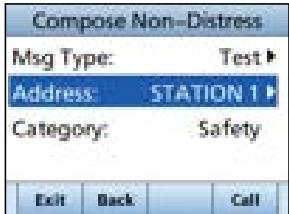
- The "Compose Non-Distress" screen is displayed.
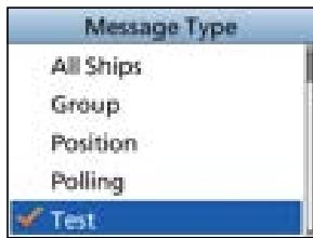
① You can also display the "Compose Non-Distress" screen by selecting the "Other DSC" item on the Menu screen. - Select "Test," and then push [ENT] or [CH/ENT].
- The Test call is selected, and returns to the "Compose Non-Distress" screen.
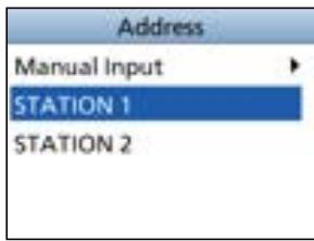
- Select "Address," and then push [ENT] or [CH/ENT].
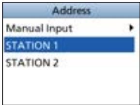
- The "Address" screen is displayed.
- Select a station to send the Test call to.
① You can also select "Manual Input" to manually enter the calling station. - Push Call to send the Test call.
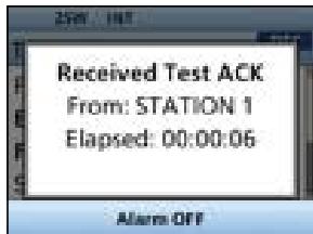
① If Channel 70 is busy, the transceiver stands by until the channel becomes clear. - When you receive an Acknowledgment:
An alarm sounds. - The screen on the right is displayed.
- Push Alarm OFF to turn OFF the alarm.
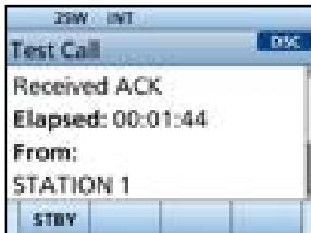
- The Acknowledgment information is displayed.
- Push Close Window.
- The received call's information is displayed.
The call is saved in the DSC Log. - Push STBY to return to the operating screen.
- "Terminate the procedure. Are you sure?" is displayed.
- Push OK to return to the operating screen.
- Returns to the operating screen.
Sending a Test Acknowledgment
By default, when you receive a Test call, the Auto ACK function automatically sends an Acknowledgment to the calling station (p. 46). If the function is set to "Manual," do the following steps to send an Acknowledgment.
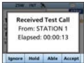
- After a Test call is being received, push Alarm OFF to turn OFF the alarm.
-
Push Accept
-
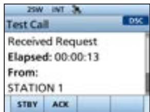
The received call's information is displayed.
-
Push ACK
-
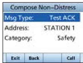
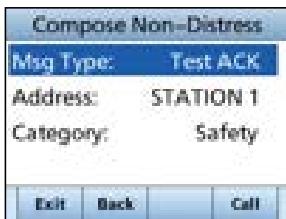
The "Test ACK" confirmation screen is displayed.
-
Push Call to send the Acknowledgment.
-
"Transmitting Test ACK" is displayed.
-
Push STBY, and then push OK to return to the operating screen.
7 DIGITAL SELECTIVE CALLING (DSC)
Sending a Position Request call/Polling Request call (For only the USA version)
You can send a Position Request call or Polling request call to a station, depending on the presetting.
- Send a Position Request call when you want to know a specific ship's current position.
- Send a Polling Request call when you want to know whether a specific ship is in the communication area, or not.
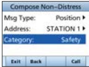
Example: Sending a Position Request call
1. Push Other DSC.
- The "Compose Non-Distress" screen is displayed.
① You can also display the "Compose Non-Distress" screen by selecting the "Other DSC" item on the Menu screen.
- Select "Msg Type," and then push [ENT] or [CH/ENT].
- Select "Position," and then push [ENT] or [CH/ENT].
① When you send a Polling Request call, select "Polling."
-
The message type is selected, and returns to the "Compose Other" screen.
-
Select "Address," and then push [ENT] or [CH/ENT].
- Select a target to send a Position Request call to, and then push [ENT] or [CH/ENT].
① You can also select "Manual Input" to manually enter the target ID.
- Push Call to send the Position Request call.
- Position Request call is sent, and then "Waiting for ACK" is displayed.
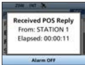
① If Channel 70 is busy, the transceiver stands by until the channel becomes clear. - When you receive a Position Reply:
An alarm sounds. - The screen on the right is displayed.
- Push Alarm OFF to turn OFF the alarm.
- Push Close Window.
- The received information is displayed.
- Push [▲] or [▼], or rotate [CH/ENT] to scroll the screen, and then check the target's position.
- Push STBY, and then OK to return to the operating screen.
Sending a Position Reply call
Send a Position Reply call when a Position Request call is received.
If the Auto ACK function is set to "Auto," the Acknowledgment is automatically sent to the calling station. (p. 46)
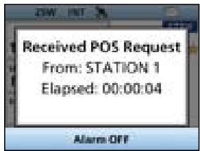
- After a Position Request is being received, push Alarm OFF to turn OFF the alarm.
The received call's information is displayed.
- Push the Software Key below the intended operation.
Ignore:
ignores the call and returns to the operating screen.
The call is saved in the DSC Log.
- "..." blinks continuously until you display the call message.
Hold:
Holds the RX call task, and returns to the Main screen.
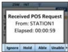
Able:
(Able to comply)
Sends Acknowledgment "Able to comply" right away.
The call is saved in the DSC Log.
- Displays the Acknowledgment information, and then returns to the operating screen by pushing STBY, and then OK.
Unable:
Sends an Acknowledgment "Unable to Comply."
(Unable to Comply.)
The call is saved in the DSC Log.
Comply)
- Displays the Acknowledgment information, and then returns to the operating screen by pushing STBY, and then OK.
7 DIGITAL SELECTIVE CALLING (DSC)
Sending a Position Reply call
Accept Accepts the call.
- Displays the received call's information.
The call is saved in the DSC Log.
Push ACK Able or ACK Unable, then push Call to send the Position Reply call.
STBY:
Closes the call, and then returns to the operating screen.
ACK Able:
(Able to
Comply)
Sends an
acknowledgment with
position and time data.
ACK Unable:
(Unable to
Comply)
Sends an
acknowledgment with no position and time data.
- Push STBY, and then OK to return to the operating screen.

Sending a Polling Reply call
Send a Polling Reply call when a Polling Request call is received.
① When "Polling ACK" is set to "Auto," the transceiver automatically sends the call.
- While a Polling Request call is being received, push Alarm OFF to turn OFF the alarm.
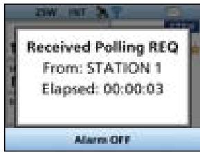
-
Push Accept
-
Enters the DSC Task mode.
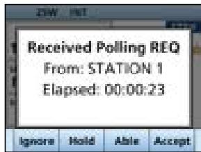
-
Push ACK
-
The call contents screen is displayed.
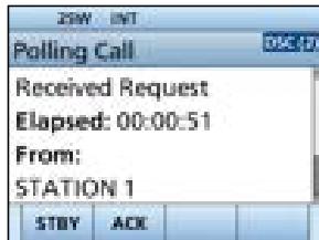
-
Push Call to send the Polling Reply.
-
"Transmitting Polling Reply" is displayed.
-
Push STBY, and then push OK to return to the operating screen.
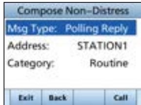
7 DIGITAL SELECTIVE CALLING (DSC)
Receiving DSC calls (Distress)
The transceiver receives Distress calls, Distress Acknowledgments, and Distress Cancel calls. When you receive a call, an emergency alarm sounds.
NOTE: The screens that are displayed when a Distress call or an Acknowledgment is received slightly differ from one another. The following steps are described using an example of receiving a Distress call.
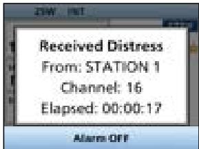
When a Distress call is received:
- The emergency alarm sounds until you turn it OFF.
-
"Received Distress" is displayed.
-
Push Alarm OFF to turn OFF the alarm.
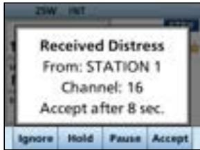
- Push the Software Key below the intended operation.
Ignore: Returns to the operating screen.
The call is saved in the DSC Log.
"blinks continuously until you display the call message.
Hold: Holds the RX call task, and returns to the Main screen.
Pause: Pause is not displayed if the "CH Auto Switch" item is set to "Manual." (p. 46)
Pauses the countdown until the assigned channel is automatically selected.
Select Resume to resume the countdown.
The call is saved in the DSC Log.
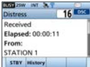
Accept: Accepts the call. Channel 16 is automatically selected. Monitor Channel 16 as a coast station may require assistance. After
Channel 16 is selected, select your next operation by pushing the Software Key below the following options.
STBY: Closes the Distress operation, and returns to the operating screen.
History: Displays the "Distress History" screen.
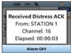
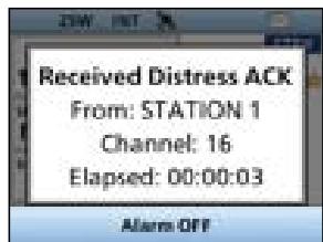
When a Distress acknowledgment is received:
- After a Distress Acknowledgments is being received, push Alarm OFF to turn OFF the alarm.
- Push Close Window.
The received information is displayed.
- Push Accept
The received information is displayed. - Push STBY.
- "Terminate the procedure. Are you sure?" is displayed.
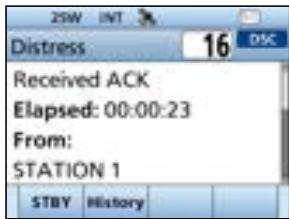
- Push OK to return to the operating screen.
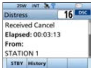
When a Distress Cancel call is received:
- Push Alarm OFF to turn OFF the alarm.
The received information is displayed.
- Push STBY, and then push OK to return to the operating screen.
7 DIGITAL SELECTIVE CALLING (DSC)
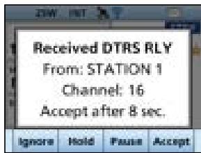
Receiving a Distress Relay call
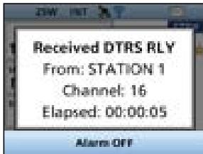
When a Distress Relay call is received:
An alarm sounds.
- The following screen is displayed and the backlight blinks.
- "..." blinks.
-
Push any Alarm OFF.
-
Push the Software Key below the next operation.
Ignore: Returns to the operating screen. The call is saved in the DSC Log. "blinks continuously until you display the call message.
Hold: Holds the RX call task, and returns to the Main screen.
Pause: Pause is not displayed if the "CH Auto Switch" item is set to "Manual." (p. 46) Pauses the countdown until the assigned channel is automatically selected. Select Resume to resume the countdown. The call is saved in the DSC Log.
Accept: Accepts the call. Channel 16 is automatically selected. Monitor Channel 16 as a coast station may require assistance. After Channel 16 is selected, select your next operation by pushing the Software Key below the following options.
STBY: Returns to the operating screen.
History: Displays the "Distress History" screen.
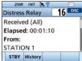
- Push STBY, and then OK to return to the operating screen.
Receiving DSC calls (other)
The transceiver receives the following types of DSC calls.
Individual call (p. 38)
- Polling Request call(p. 34)
- Individual Acknowledgment (p. 26)
Test call (p. 41)
- Group call / All Ships call (p. 39)
- Test Acknowledgment / Position Reply call / Polling Reply call (p. 42)
- Position Request call (p. 40)
① The receivable call types may differ, depending on the transceiver version or presetting.
By default, the Auto ACK function automatically sends an Acknowledgment to the calling station. ([MENU] > Settings > DSC > Auto ACK (p. 46))
If Auto ACK is set to "Manual," you can manually send an Acknowledgment for each call as described in this section.
Receiving an Individual call
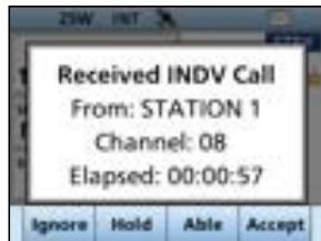
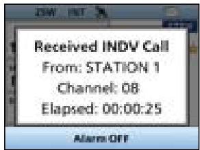
When an Individual call is received:
An alarm sounds.
- "Received INDV Call" is displayed.
- Push Alarm OFF to turn OFF the alarm.
- Push the Software Key below the next operation.
Ignore: Ignores the call and returns to the operating screen.
The call is saved in the DSC Log.
- "blinks continuously until you display the call message.
Hold: Holds the RX call task, and returns to the Main screen.
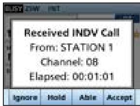
Able: Sends an Individual Acknowledgment right (Able to away.
comply) • Automatically switches to the assigned channel.
- After sending, push Resend to resend.
The call is saved in the DSC Log.
Accept. Accepts the call.
The call is saved in the DSC Log.
- The received call's information is displayed.
- Push the Software Key to select the Acknowledgment option.
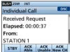
STBY:
ACK Able:
(Able to Comply)
ACK Unable:
(Unable to Comply)
ACK New CH:
(Propose New CH)
Push to delete the task and returns to the Main screen.
Sends an Acknowledgment without any changes.
Sends an Acknowledgment but cannot communicate.
Able to communicate but proposes another channel.
Specify the channel by pushing [ ] or [ ]
7 DIGITAL SELECTIVE CALLING (DSC)
Receiving a Group call or All Ships call
When a Group call is received:
An alarm sounds.
- "Received Group Call" is displayed.
When an All Ships call is received:
An alarm sounds.
- "Received All Ship Call" is displayed.
-
Push Alarm OFF to turn OFF the alarm.
-
The channel that is assigned by the caller is automatically selected after 10 seconds by default.
-
Push the Software Key below your next operation.
Ignore: Ignores the call and returns to the operating screen.
The call is saved in the DSC Log.
- "..." blinks continuously until you display the call message.
Hold: Holds the RX call task, and returns to the Main screen.
Pause: Pauses the countdown until the assigned channel is automatically selected.
- Select Resume to resume the countdown.
The call is saved in the DSC Log.
① Pause is not displayed if the "CH Auto Switch" item is set to "Manual." (p. 46)
Accept Accepts the call.
- The assigned channel is selected.
The call is saved in the DSC Log.
STBY: Closes the call, and then returns to the operating screen.
(Example: when a Group call is received)
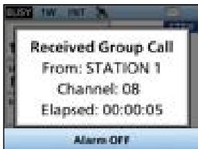
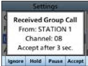
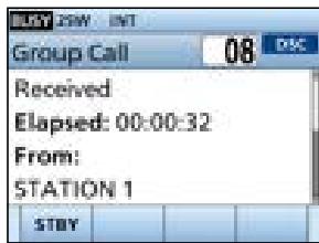
Receiving a Position Request call
(May not be used, depending on the presetting)
NOTE: Even if the Auto ACK function is set to "Manual" while waiting to receiving a distress acknowledgment or after receiving a distress acknowledgment, the Position Reply is automatically sent to the calling station.
When a Position Request call is received:
An alarm sounds.
- "Received POS Request" is displayed.
- Push Alarm OFF to turn OFF the alarm.
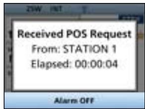
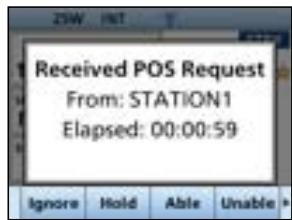
- Push the Software Key below the intended operation.
Ignore: Ignores the call and returns to the operating screen.
The call is saved in the DSC Log.
- "..." blinks continuously until you display the call message.
Hold: Holds the RX call task, and returns to the Main screen.
Able: Sends Acknowledgment "Able to comply" (Able to right away.
comply)
Unable: Sends an Acknowledgment "Unable to (Unable to Comply."
Comply) The call is saved in the DSC Log.
- Displays the Acknowledgment information, and then returns to the operating screen by pushing STBY, and then OK.
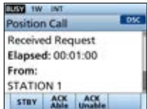
Accept Accepts the call.
- Displays the received call's information.
The call is saved in the DSC Log.
Push ACK Able or ACK Unable, then push Call to send the Position Reply call. (p. 32)

7 DIGITAL SELECTIVE CALLING (DSC)
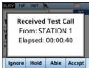
Receiving a Test call
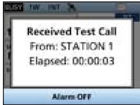
When a Test call is received:
An alarm sounds.
"Received Test Call" is displayed.
- Push Alarm OFF to turn OFF the alarm.
- Push the Software Key below your next operation.
Ignore: Ignores the call and returns to the operating screen.
The call is saved in the DSC Log.
- "..." blinks continuously until you display the call message.
Hold: Holds the RX call task, and returns to the Main screen.
Able: Sends a Test Acknowledgment "Able to (Able to Comply."
comply) · The call is saved in the DSC Log.
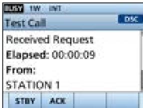
Accept: Accepts the call.
- Displays the received call's information.
The call is saved in the DSC Log. - The received call's information is displayed.
Push ACK, and then push Call to send a Test Acknowledgment. (p. 30)
Push Resend to resend.
Receiving a Test acknowledgment/Position Reply call* /Polling Reply call (*For only the USA version)
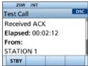
Example: Receiving a Test acknowledgment
When a call is received:
An alarm sounds.
- The following screen is displayed and the backlight blinks.
- " " blinks.
- Push Alarm OFF to turn OFF the alarm.
-
Push Close Window
-
The received information is displayed.
-
Push STBY.
-
"Terminate the procedure. Are you sure?" is displayed.
-
Push OK to return to the operating screen.

7 DIGITAL SELECTIVE CALLING (DSC)
DSC Log
Received DSC Log
The transceiver saves up to 30 received Distress call messages and 50 received "Others" call messages in your DSC Log.
On the operating screen, "..." is displayed when there is an unread call message.
The icon blinks when there is a new received call message.
- Open the "DSC Log" screen.
[MENU] > DSC Log
-
Select "Received Call Log," and then push [ENT].
-
The "Received Call Log" screen is displayed.
-
Select "Distress" or "Others," and then push [ENT].
① "Distress" displays the received Distress call log, and "Others" displays the received DSC call log.
TIP: You can also display the "Received" screen by pushing DSC Log on the operating screen.
- Select a log, and then push [ENT], [CH/ENT], or
INFO to display the detailed information.
INFO: Displays the detailed information.
Delete: deletes the selected call log.
MMSI: Saves the MMSI as an Individual ID.
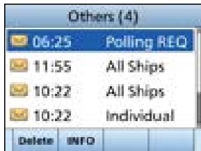
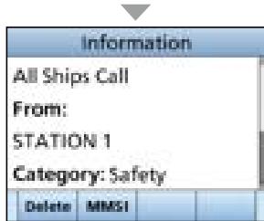
Transmitted DSC Log
The transceiver saves up to 30 DSC transmitted calls in your DSC Log.
- Open the "DSC Log" screen.
[MENU] > DSC Log
-
Select "Transmitted Call Log," and then push [ENT].
-
The "Transmitted Call Log" screen is displayed.
-
Select a log, and then push [ENT] to display the detailed information.
INFO: Displays the detailed information.
Delete: deletes the selected call log.
MMSI: Saves the MMSI as an Individual ID or a Group ID.
Multiple-task mode
(For only the USA version, depending on the presetting)
If the Multiple-task function is enabled, the transceiver can hold up to 7 tasks. You can handle more than 2 DSC tasks simultaneously by switching between the tasks. To use the Multiple-task mode, select "Multiple" in the "Procedure" on the Menu screen. (p. 47)
[MENU] > Settings > DSC > Procedure
When the Multiple-task mode is activated, TaskList is displayed on the operating screen.
NOTE: The Task mode has an Inactivity Timer function. After a certain period of time has passed without any operation on a task, the transceiver automatically deletes a task and returns to the operating screen.
When an Inactivity Timer activates, an alarm sounds and a count down message is displayed for 10 seconds.
Holding a DSC task
In the Multiple-task mode, you can hold or activate the DSC task as follows.
Example: When a Group call is received:
- Push Alarm OFF to turn OFF the alarm.
- The received call's information is displayed.
- Push Hold
- The received Group call task is held into the task list and returns to the operating screen.
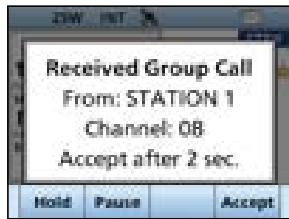
Activating the held DSC task
- Push TaskList to display the task list.
- The task list is displayed.
- Select the task that you want to activate.
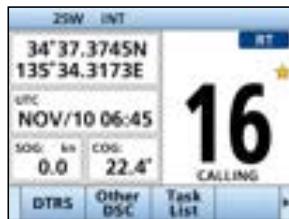
- Push Active to activate the task.
- The activated task information is displayed.
- Push [PTT] to communicate.
- After finishing the communication, push Delete to delete the task.
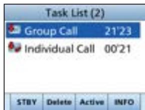
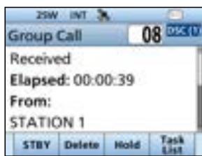
7 DIGITAL SELECTIVE CALLING (DSC)
Task list
You can display the task list screen by pushing TaskList The number of tasks is displayed at the top of the screen.
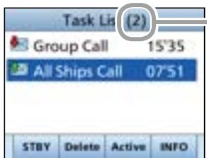
The number of tasks
On the "Task List" screen, the following Software Keys are displayed.
STBY: Holds the task and returns to the operating screen.
Delete: Finishes the selected task.
Active: Activates the selected task.
Hold: Holds the selected task.
INFO: Displays the task information.
DSC Settings
On the "DSC" screen, you can make settings of the DSC call related items.
[MENU] > Settings > DSC
Position Input
See "Entering the position and time" on page 20 for details.
Individual ID
See "Entering an Individual ID" on page 19 for details.
Group ID
See "Entering a Group ID" on page 19 for details.
Auto ACK
The Auto ACK function automatically sends an Acknowledgment when an appropriate Request is received.
- Individual ACK
Auto (Able): Automatically sends "Able to comply."
Auto (Unable):Automatically sends "Unable to comply."
Manual: Manually sends an Acknowledgment.
- Position ACK
Auto (Able): Automatically sends "Able to comply."
Manual: Manually sends an Acknowledgment.
- Polling ACK
Auto: Automatically sends an Acknowledgment.
Manual: Manually sends an Acknowledgment.
Test ACK
Auto: Automatically sends an Acknowledgment.
Manual: Manually sends an Acknowledgment.
CH Auto Switch
Select whether or not to automatically switch to channel 16 or the specified channel, or ignore the call.
Accept after 10 sec.:
After receiving a DSC call, the transceiver remains on the operating channel for 10 seconds. After that, the transceiver automatically switches to the channel that is specified on the DSC call.
Ignore after 10 sec.:
After receiving a DSC call, if you do not push the Software Key below Accept in 10 seconds, the transceiver ignores the call, and then remains on the current operating channel.
Manual:
After receiving a DSC call, you can select whether or not to accept the received DSC call.
NOTE: In the Multiple-task mode, "Ignore" is renamed to "Hold after 10 sec."
DSC Data Output
When receiving a DSC call from the station that is selected in this setting, the transceiver outputs the DSC data to the NMEA output port.
① You can send Distress calls despite of this setting.
All Stations: From any station.
Stations List: From the stations that are entered Individual ID or Group ID on the Menu screen.
OFF: Does not output any DSC data to an external device.
7 DIGITAL SELECTIVE CALLING (DSC)
DSC Settings
Alarm Status
Sets the alarm ON or OFF when receiving each type of DSC call.
Safety
Routine
- Warning
Sets the alarm for when:
- No MMSI code is entered.
- The position data has not been received for 30 minutes after turning ON the transceiver.
- The received position data has not been updated for 10 minutes.
- The position data has not been updated for 4 hours.
- The position data has not been updated for 23.5 hours.
Self-Terminate
An alarm sounds when duplicate Distress calls are received.
- Discrete
An alarm sounds when a lower priority call is received while receiving a high priority call.
CH 70 SQL Level
Sets the Squelch level for Channel 70 to 1 10 or Open.
Self Check Test
The Self-Test sends DSC signals to the receiving AF circuit to compare the sending and receiving signals at the AF level.
Push [ENT] to start the Self-Test.
① When the sending and receiving DSC signals match, "OK" is displayed.
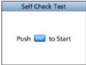
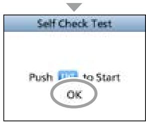
Procedure (For only the USA version)
You can select the type of task for the transceiver, depending on the presetting.
Single: Handles only 1 task at the same time.
Multiple: Handles up to 7 tasks at the same time.
Making an Individual call to an AIS target
You can transmit an Individual call to a selected AIS target, without entering the target's MMSI code. In this case, the call type is automatically set to Routine.
Selecting an AIS target on the IC-M510/IC-M510E
You can compose an Individual call to an AIS target selected on the Plotter screen or the AIS list.
NOTE: The IC-M510/IC-M510E can be input AIS information from the built-in AIS receiver (if built in) or an external NMEA 0183 or NMEA 2000 sentence source.
- Select the AIS target from the Plotter screen, the Target List, the Friends List, or the Danger list (pp. 52, 55).
- Push DSC
"Compose Non-Distress" screen is displayed.
- Select "Channel," then push [ENT] or [CH/ENT] to display the Voice channel selection screen.
① See page 25 for details. - Select a channel to assign, and then push [ENT] or [CH/ENT].
- Push Call to send the Individual call.
-
When you receive an Acknowledgment "Able to comply", an alarm sounds. Push Alarm OFF to turn OFF the alarm.
-
The channel assigned in step 4 is automatically selected.
If the called station cannot use the channel that you assigned, a different channel is selected by the other station. -
Push Close Window
- Hold down [PTT] to communicate.
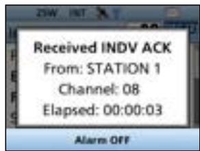
Using an AIS transponder
When the optional MA-510TR CLASS B AIS TRANSPONDER is connected to the transceiver, you can transmit an Individual call to a selected AIS target and the voice channel on the transponder.
① See page 97 for connecting instructions.
NOTE: To ensure correct operation of the DSC function, make sure you correctly set the CH70 SQL Level. (p. 47)
① See the next page for the operation.
7 DIGITAL SELECTIVE CALLING (DSC)
Using an AIS transponder
Transponder operation:
- Select an AIS target on the plotter display, Target, Danger, or Friends list screen.
① See the MA-510TR INSTRUCTION MANUAL for details.
- Push [ENT] to display the Menu window.
- The Menu window is displayed.
- Select "Send DSC," and then push [ENT].
-
The "DSC TRANSMISSION" screen is displayed.
-
Push [▲] or [▼] to select a voice channel.
-
Voice channels are already preset into the transponder in the recommended order.
NOTE: When a base station is selected in step 1, a voice channel will be specified by the base station. Therefore you cannot change the channel. The transponder will display "Voice Channel is specified by the Base station," in this case.
-
Push [ENT] to make the Individual DSC call.
-
"Transmitting individual call" is displayed.
① If Channel 70 is busy, the transceiver stands by until the channel becomes clear.
-
After making the Individual DSC call, "DSC transmission completed." is displayed.
-
If the transceiver cannot make the call, "DSC transmission failed." is displayed.
Transceiver operation:
-
When the acknowledgment is received, alarm sounds.
-
If the acknowledgment 'Able to comply' is received, push Alarm OFF to stop the alarm, and then select the voice channel specified in step 4.
-
A different voice channel will be selected if the station you called cannot use the channel.
- To reply, push [PTT] and speak at a normal voice level.
- You can check the MMSI code or the name, if entered, of the AIS target on the display.
-
If the acknowledgment 'Unable to comply' is received, push Alarm OFF to stop the alarm, then the Acknowledge information is displayed.
-
After the communication is finished, push STBY to return to the normal operating mode.
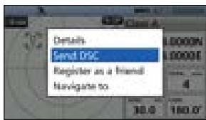
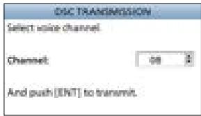
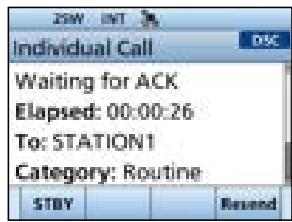
NOTE: The IC-M510/IC-M510E can be input AIS information from the built-in AIS receiver (if built in) or an external NMEA 0183 or NMEA 2000 sentence source.
About AIS
The Automatic Identification System (AIS) is primarily used for collision-risk management and navigation safety. It can automatically transmit and receive vessel information, such as the vessel name, MMSI code, vessel type, position data, speed, course, destination, and more, depending on the class. Information is exchanged among vessels and/or base stations on the VHF maritime mobile band. The information helps to identify other nearby vessels or stations by displaying the received data on a plotter or a radar screen.
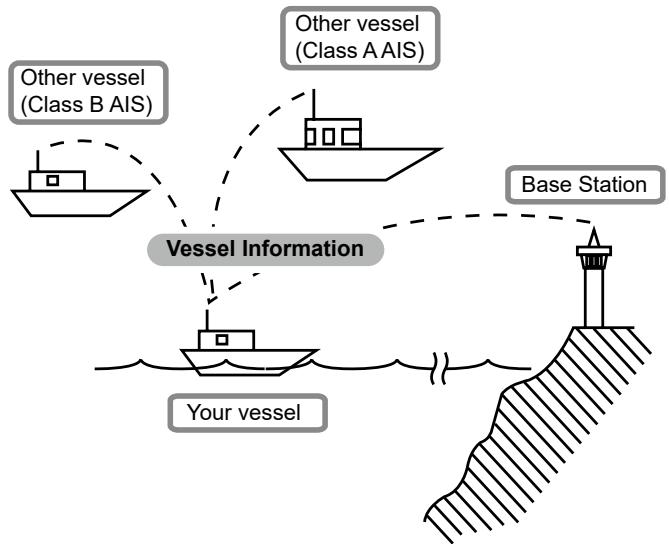
■ AIS classes
There are 7 types of AIS stations, vessels, base stations, Search and Rescue (SAR), Aids to Navigation (AtoN), Search and Rescue Transmitter (AIS-SART), Man OverBoard (MOB), and Emergency Position Indicating Radio Beacon-AIS (EPIRB-AIS).
There are 2 classes of AIS units, which are installed on vessels, Class A and Class B.
Under the Safety Of Life At Sea (SOLAS) convention, all SOLAS vessels, as described below, are required to install a Class A AIS transponder:
- Upwards of 300 gross tonnage engaged on international voyages.
- Passenger vessels, irrespective of size, engaged on international voyages.
- Upwards of 500 gross tonnage not engaged on international voyages.
A Class B AIS transponder is designed to be interoperability with Class A units, but not to impact the Class A network.
Many commercial vessels, and some leisure craft, not classified as requiring a Class A unit, choose to install a Class B unit to avoid accidents at sea.
Using the Plotter screen
On the plotter screen, the display range and the icons of the AIS target, waypoint and MOB are displayed. You can change the display range and type, depending on your operating style.
- Push [DISP] and then select "Plotter".
- The Plotter screen is displayed.
- Push the Software Key for your next operation.
Range: Selects the display range. (p. 52)
Target Select Selects the closest target to your (Select) vessel.
Target Select: Selects the farthest target from your vessel.
Target Details: Displays the details on the selected (Details) target. (p. 57)
WPT: Push to save your position information to the transceiver.
NAV: Push to start navigation.
Stop NAV: While navigating, push to stop navigation.
MOB: Push to enter the Man Overboard (MOB) mode. (p. 65)
Stop MOB: While in the Man Overboard (MOB) mode, push to stop the Man Overboard (MOB) mode.
Anchor: Push to start the Anchor watch function. (p. 66)
Stop Anchor: While in the Anchor watch mode, push to stop Anchor watch.
NOTE: An alarm sounds when an AIS target is closer than the CPA (Closest Point of Approach) and TCPA (Time to CPA) settings, and so on, depending on the presetting. To stop the alarm buzzer, push any key. ① If a popup screen is displayed, push any key again to turn it OFF.
TIP: You can display only the Plotter screen by selecting the "Plotter" item on the Menu screen.
[MENU] > AIS > Plotter

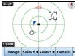
Plotter screen
Displays the plotter display and selected target's information.
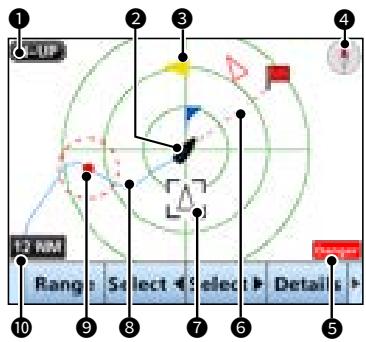
DISPLAY TYPE
Displays the selected display type. You can select the display type in "North up/ Course up" on the Menu screen. (p. 59)
$$ \begin{array}{l} \text {[ M E N U ] > S e t t i n g s > A I S >} \ \text {N o r t h u p / C o u s e u p} \end{array} $$
① When “N-UP” is displayed, the top of the plotter screen represents North.
① When "C-UP" is displayed, the top of the plotter screen represents the direction your vessel's course over ground.
2 YOUR VESSEL ICON
Displayed in the center of the screen.
① When “N-UP” is displayed, the vessel icon automatically points in the direction your vessel is heading, in 5.625 degree steps.
① When "C-UP" is displayed, the vessel icon constantly points to the top of the plotter screen.
① When your vessel moves less than 2 knots, is displayed.
3 TARGET ICONS
Targets whose AIS signal are received are displayed with icons. The icon may differ, depending on the target type or its status.
| Icon | Description |
| AIS target: Vessel ① The tip of the target triangle automatically points in the direction it's heading. | |
| AIS target: Vessel (Friend) (Yellow triangle) | |
| AIS target: AIS-SART, AIS-MOB, and EPIRB-AIS | |
| AIS target: Search and Rescue (SAR) vessel | |
| AIS target: Search and Rescue (SAR) aircraft | |
| AIS target: Aids to Navigation (AtoN) | |
| AIS target: Aids to Navigation (AtoN) virtual | |
| AIS target: Base station | |
| Waypoint ① is displayed during navigation. | |
| MOB |
① Icons for other than the SAR aircraft, Base station, Waypoint, and MOB are displayed in red (Day mode) or white (Night mode) (pp. 12, 82), when the AIS target is closer than your CPA and TCPA settings (Danger target).
① A vessel is regarded as a "Lost target," and a red cross mark displays on the target icon after a specified period of time has passed since the vessel last transmitted data (p. 71). The Lost target icon disappears from the plotter display 6 minutes and 40 seconds after the vessel was regarded as a "Lost target." Ask your dealer for details.
4 COMPASS
Displays the bearing information.
8 AIS FUNCTION
Plotter screen
DISPLAY FILTER INDICATOR
Displayed when the type of targets on the plotter screen are filtered. (p. 59)
[MENU] > Settings > AIS > Target Display
| Indicator | Description |
| Danger | Only Danger AIS targets are displayed. |
| Friends | Only Friend AIS targets are displayed. |
| Waypoint | Only waypoints are displayed. |
| No indicator | All targets are displayed. |
⑥ NAVIGATION LINE
Displays a line from the start position of navigation to the AIS target or waypoint.
7 TARGET BOX
Displays the selected target.
When a target box is displayed, push Target Details to display the detail screen of the selected target.
VESSEL TRACK
Displays your vessel track.
ANCHOR WATCH
- Displays (a red circle) as the start position of anchor watch.
- Displays a red dashed circle as the range of anchor watch.
10 DISPLAY RANGE
- Displays the selected display range.
- Push Range to select the desired display range.
① 0.125, 0.25, 0.5, 0.75, 1.5, 3, 6, 12, 24, 36 NM (nautical miles) are selectable.
Using the AIS list screen
There are 3 types of AIS lists, Target, Danger, and Friends.
The target's information is automatically updated every 5 seconds, and then the AIS target data is sorted.
- Push [MENU].
- The Menu screen is displayed.
- Push [] , [] , or rotate [CH/ENT] to select "AIS," and then push [ENT], [CH/ENT], or [] .
- The "AIS" screen is displayed.
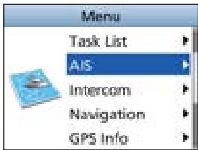
- Push [▲] or [▼] to select a list, and then push [ENT], [CH/ENT], or [▶].
- The list screen is displayed.
- Push [], [] , or rotate [CH/ENT] to select an AIS target.
- Push the Software Key below for your next operation.
DSC: Displays the "Compose Non-Distress" screen to send an Individual call. (p. 25)
① Displayed only when a target is selected.
NAV: Starts navigation to the selected (Navigation) target. (p. 67)
Friend: Sets the selected target as a Friend. (p. 56)
① Displayed only in the Target List or Danger List.
Details: Displays the details on the selected target. (p. 57)
① Displayed only when the target is selected.
Disp on Plotter. Displays the selected target on the plotter screen. (p. 51)
Sort: Sorts the Danger target data by CPA or TCPA.
① Displayed only in the Danger List.
NOTE: An alarm sounds when an AIS target is closer than the CPA and TCPA settings, and so on, depending on the presetting. To stop the alarm buzzer, push any key.
① If the popup screen is displayed, push any key again to turn it OFF.
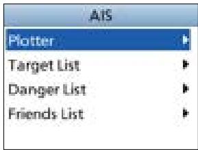
8 AIS FUNCTION
Target/Friends List screen
The Target List screen displays up to 200 AIS targets.
The Friends List screen displays the AIS targets of up to 100 targets that you set as a Friend. (p. 56)
The AIS target data is sorted by the distance from your vessel, and the closest target is located at the top of the list.
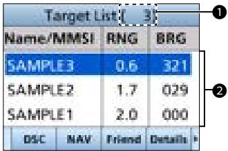
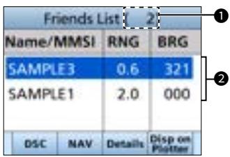
1 THE NUMBER OF TARGETS
Displays the number of AIS targets.
2 TARGET INFORMATION
Displays the following AIS target information.
- MMSI code or name
- Range (RNG) from your vessel to the target (units: NM)
- Bearing (BRG) from your vessel to the target (units: degree)
Danger list screen
The Danger List screen displays any Danger target whose CPA (Closest Point of Approach) distance and TCPA (Time to CPA) time are less than the set values. You can set the values in "CPA" and "TCPA" on the Menu screen. (p. 59)
$$ \begin{array}{l} \text {[ M E N U ] > S e t t i n g s > A I S > C P A / T C P A >} \ \text {C P A o r T C P A} \end{array} $$
① The transceiver can display up to 200 targets.
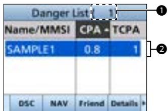
1 THE NUMBER OF TARGETS
Displays the number of AIS targets.
DANGER TARGET INFORMATION
Displays the following AIS target information.
- MMSI code or name
- CPA: Closest Point of Approach (unit: NM)
- TCPA: Time to CPA (units: minute)
Setting a Friend
You can set up to 100 AIS targets as a Friend in the Friends List.
An alarm sounds when a Friend is detected, depending on the setting. (p. 60)
Entering an ID
There are 3 ways of setting a Friend, using the Friends List, selecting in the AIS list, or selecting on the plotter display.
Using the Friends List:
- Open the "Friends List" screen.
[MENU] > Settings > AIS > Friends > Friends List
-
"No ID" is displayed when there is no Friend.
-
Push Add to display the Friend ID window.
- Enter an ID.
TIP:
- Select a number using [] and [] .
- Push [ENT], or [CH/ENT] to enter the selected number.
-
Select "←" or "→" on the screen, or rotate [CH/ENT] to move the cursor.
-
Push Finish to save the edited ID.
-
The target is added to the Friends List.
Selecting in the Target List or Danger List:
- Open a "Target List" or a "Danger List".
[MENU] > AIS > Target List or Danger List
- Push [ ] or [ ] ,or rotate [CH/ENT] to select an AIS target.
- Push Friend
"Register as a Friend," is displayed.
- is displayed.
Selecting on the plotter display:
- Open the plotter screen. (p. 51)
- Push Target Select or Target Select to select an AIS target.
-
Push Details to display the details screen.
-
The "Details" screen is displayed.
-
Push Friend
-
The target is added to the Friends List.
- A friend target is displayed with (yellow triangle) on the plotter screen.
Editing an ID
- Open the "Friends List" screen.
[MENU] > Settings > AIS > Friends > Friends List
- Push [ ] or [ ] , or rotate [CH/ENT] to select an ID.
- Push Edit
① See step 3 in "Using the Friends List," as described to the left.
Deleting an ID
- Open the "Friends List" screen.
[MENU] > Settings > AIS > Friends > Friends List - Push [ ] or [ ] , or rotate [CH/ENT] to select an ID.
- Push Delete
- "Delete the ID. Are you sure?" is displayed.
- Push OK
About the Detail screen
The Detail screen displays the information about the selected AIS target or waypoint. The contents may differ, depending on the selected target.
① When a Danger target is selected, is displayed.(p. 55)
① When a Friend target is selected, is displayed. (p. 55)
- Push the Software Key below for your next operation.
DSC: Displays the "Compose Non-Distress" screen to send an Individual call. (p. 25)
NAV:Starts navigation to the selected target. (p. 67)
Friend: Sets the selected target as a Friend. (p. 56)
① A beep sounds and a popup screen is displayed when the memory is full.
MMSI: Displays the Individual ID entry screen. (p. 8)
① A beep sounds and a popup screen is displayed when the memory is full, or the ID has been already added.
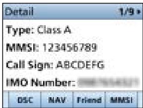
Contents list
NOTE: The contents may differ, depending on the received data.
| Class A and SAR vessel |
| AIS class |
| MMSI code |
| Ship name |
| Country name |
| Call sign |
| Vendor ID |
| IMO number |
| CPA (Closest Point of Approach) |
| TCPA (Time to CPA) |
| Position (Latitude, Longitude) |
| SOG (Speed Over Ground) |
| COG (Course Over Ground) |
| HDG (Heading) |
| PA (Position Accuracy (H: High, L: Low)) |
| Range |
| Bearing |
| ROT (Rate Of Turn) |
| Bow to antenna distance |
| Stern to antenna distance |
| Port side to antenna distance |
| Starboard side to antenna distance |
| Length |
| Beam |
| Draught |
| Type of ship |
| NAV Status |
| Destination |
| Estimated time of arrival |
| Elapsed time |
| Class B |
| AIS class |
| MMSI code |
| Ship name |
| Country name |
| Call sign |
| Vendor ID |
| CPA (Closest Point of Approach) |
| TCPA (Time to CPA) |
| Position (Latitude, Longitude) |
| SOG (Speed Over Ground) |
| COG (Course Over Ground) |
| HDG (Heading) |
| PA (Position Accuracy (H: High, L: Low)) |
| Range |
| Bearing |
| Bow to antenna distance |
| Stern to antenna distance |
| Port side to antenna distance |
| Starboard side to antenna distance |
| Length |
| Beam |
| Type of ship |
| Elapsed time |
| AIS-SART, AIS-MOB, and EPIRB-AIS |
| AIS class |
| MMSI code |
| CPA (Closest Point of Approach) |
| TCPA (Time to CPA) |
| Position (Latitude, Longitude) |
| SOG (Speed Over Ground) |
| COG (Course Over Ground) |
| HDG (Heading) |
| PA (Position Accuracy (H: High, L: Low)) |
| Range |
| Bearing |
| ROT (Rate Of Turn) |
| Elapsed time |
| Base station |
| AIS class |
| MMSI code |
| Position (Latitude, Longitude) |
| PA (Position Accuracy (H: High, L: Low)) |
| Vendor ID |
| Range |
| Bearing |
| Elapsed time |
| SAR aircraft |
| AIS class |
| MMSI code |
| Target name |
| Country name |
| Call sign |
| Vendor ID |
| Position (Latitude, Longitude) |
| SOG (Speed Over Ground) |
| COG (Course Over Ground) |
| ALT (Altitude) |
| PA (Position Accuracy (H: High, L: Low)) |
| Range |
| Bearing |
| Length |
| Width |
| Elapsed time |
| AtoN and AtoN virtual |
| AIS class |
| MMSI code |
| Target name |
| CPA (Closest Point of Approach) |
| TCPA (Time to CPA) |
| Position (Latitude, Longitude) |
| PA (Position Accuracy (H: High, L: Low)) |
| Position indicator (ON POSN: ON Position, OFF POSN: OFF Position) |
| Range |
| Bearing |
| Bow to antenna length |
| Stern to antenna length |
| Port side to antenna length |
| Starboard side to antenna length |
| Length |
| Beam |
| Type of AtoN |
| Elapsed time |
| Waypoint |
| Name |
| Position (Latitude, Longitude) |
| Range |
| Bearing |
| MOB |
| Position (Latitude, Longitude) |
| Range |
| Bearing |
■ AIS settings
AIS settings can be customized in "AIS" on the Menu screen.
[MENU] > Settings > AIS
North up/Course up
You can select the display type for the plotter screen.
North up: The top of the plotter screen represents North.
Course up: The top of the plotter screen represents the direction your vessel's course over ground.
Target Display
You can select whether or not to limit the AIS or waypoint targets that are displayed on the plotter display. You can easily see the plotter display.
① The indicator is displayed on the plotter display. (p. 56)
① The waypoint for navigation is displayed, regardless of this setting.
All targets: All targets are displayed.
Danger only: Only Danger AIS targets are displayed.
Friends only: Only Friend AIS targets are displayed.
Waypoint only: Only waypoints are displayed.
CPA/TCPA
- Alarm
You can select whether or not to turn the following alarm functions ON or OFF.
ON: The alarm function is ON. An alarm sounds, and a popup screen is displayed.
① The alarm may not sound, depending on the "Audible Alarm" setting.
OFF: The alarm function is OFF.
- Approach
The alarm function for when a vessel's CPA is closer, and TCPA is less than the set value.
- Lost
The alarm function for when a danger target is regarded as a "Lost target." (p. 71)
Audible Alarm
You can select whether or not to sound the following alarms.
ON: The alarm sounds.
OFF: The alarm does not sound.
- Approach
The alarm function for when a vessel's CPA is closer, and TCPA is less than the set value.
- Lost
The alarm function for when a danger target is regarded as a "Lost target." (p. 71)
- CPA
Set a CPA (Closest Point of Approach) value between 0.01 and 6.00 NM (in 0.01 NM steps) for the alarm function.
- TCPA
Set a TCPA (Time to CPA) value between 1 and 60 minutes (in 1 minute steps) for the alarm function.
Slow Warn
The GPS receiver calculated COG data of a vessel that is at anchor or drifting is unreliable, and therefore the CPA and TCPA data may not be calculated correctly. If a vessel is anchored in your alarm zone, the unreliable data can cause the collision alarm to sound many times, even if there is no real danger. To prevent this, when the anchored vessel's SOG is less than this set value, the Slow Warn function assumes that vessel's COG is fixed towards your vessel and an alarm will sound.
- Function
Turn the Slow warn function ON or OFF.
ON: The Slow warn function is turned ON.
OFF:The Slow warn function is turned OFF.
- Speed
Set a speed for the Slow warn function between 0.1 and 4.9kn (in 0.1 kn steps).
NOTE: If other vessels at anchor or drifting come into your alarm zone, the Slow warn alarm will sound again. Only if the previous vessel disappears from the Danger list (p. 55), and then re-enters the list, can a new Slow warn or regular alarm sound, depending on the vessel's SOG, or CPA and TCPA. The Slow warn function operates in the same way if your vessel is at anchor and other vessels enter your alarm zone.
Friends
- Friends List
Displays all Friend targets that you have entered.
① “No ID” is displayed when there is no Friend target.
① See page 56 for how to set a Friend.
- Friends Alarm
- Function
You can select whether or not to turn the following alarm function ON or OFF when a vessel that is entered into the Friends List is detected.
ON: The alarm function is ON. An alarm sounds, and a popup screen is displayed when a vessel that is entered into the Friends list is detected, regardless of the set range.
ON
(in range):The alarm function is ON when a vessel that has entered into the Friends list is detected in the set range.
OFF: The alarm function is OFF.
Audible Alarm
You can select whether or not to sound the Friends alarm.
ON: The alarm sounds.
OFF:The alarm does not sound.
Range
Set the range to between 0.01 and 6.00 NM (in 0.01 NM steps) for the alarm function.
8 AIS FUNCTION
■ AIS settings
ID Blocking
The transceiver blocks AIS transponders that are entered into the ID Blocking list. Enter your vessel's transponder ID or other vessel's transponder IDs if necessary to prevent the transceiver from detecting them as dangerous targets.
① You can enter up to 10 MMSI codes.
- Entering an ID
- Open the "ID blocking" screen.
[MENU] > Settings > AIS > ID Blocking
- The blocked AIS transponder's ID is displayed.
-
"No ID" is displayed if there is no blocked AIS transponder.
-
Push Add to start the ID entry.
-
Enter an ID.
TIP:
- Select a number using [▲] and [▶].
- Push [ENT] or [CH/ENT] to enter the selected number.
-
Select "←" or "→," or rotate [CH/ENT] to move the cursor.
-
Select "Finish," and then push [ENT] to enter the ID.
- Editing an ID
- Open the "ID Blocking" screen.
[MENU] > Settings > AIS > ID Blocking
- Push [] or [] to select an ID.
-
Push Edit
-
See step 3 in "Entering an ID," as described above.
-
Push OK
- Deleting an ID
- Open the "ID Blocking" screen.
[MENU] > Settings > AIS > ID Blocking
- Push [▲] or [▼] to select an ID.
-
Push Delete
-
"Delete the ID. Are you sure?" is displayed.
-
Push OK
NOTE: For the other functions, the transceiver must be receiving valid GPS signals, or your position must be entered. (p. 20)
Waypoint
Waypoints are position data points of places you want to go to, the position of your vessel, or a vessel you received a DSC call from. You can enter up to 100 waypoints with names of up to 15 characters. You can enter your current position data, or add one as a destination or landmarks you often go to, for easy access.
Using the Waypoint list screen
The transceiver saves up to 100 waypoints in the Waypoint list.
- Open the "Waypoint" screen.
[MENU] > Navigation > Waypoint
① You can also add your current position as a waypoint by pushing Add.
- Push [▲] or [▼], or rotate [CH/ENT] to select a waypoint.
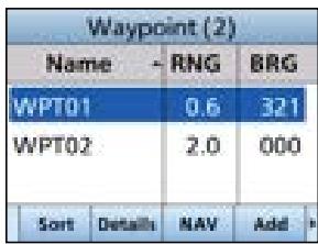
- Push the Software Key below for your next operation.
Sort: Sorts the waypoints by Name or Range.
Details: Displays the details on the selected waypoint.
① You can also edit or delete the waypoint, or start navigating to the waypoint on the "Detail" screen.
NAV: Starts navigating to the selected (Navigation) waypoint. (p. 68)
Add: Enters a waypoint. (p. 63)
Edit: Edits the selected waypoint. (p. 64)
Delete: Deletes the selected waypoint. (p. 64)
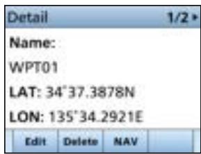
9 OTHER FUNCTIONS
Entering a waypoint
The position information that you want to memorize can be added as a waypoint.
NOTE: You can also add your current position as a waypoint by pushing WPT.
- Open the "Waypoint" screen.
[MENU] > Navigation > Waypoint
-
Push Add to add a waypoint.
-
Enter a name.
-
The "Name:" screen is displayed.
TIP:
- Select to enter numbers and letters, and to enter symbols.
- Select a number, character, or space using [] , [] , [] , and [] .
- Push [ENT] or [CH/ENT] to enter the selected number or character.
-
Select “←” or “→” on the screen, or rotate [CH/ENT] to move the cursor, or to select the entered character.
-
Repeat step 3 to enter the name of up to 15 characters.
-
Select Next, and then push [ENT] or [CH/ENT] to save the name.
-
The "LAT:" screen is displayed.
① If you do not enter a name, a popup screen is displayed. Push any key to return to the previous screen.
- Enter a latitude.
① When GPS data is received, your current position information is automatically displayed.
-
Select Next, and then push [ENT] or [CH/ENT] to save the latitude.
-
The "LON:" screen is displayed.
① If you enter a latitude that is out of the range, a popup screen is displayed. Push any key to return to the previous screen.
- Enter a longitude.
① When GPS data is received, your current position information is automatically displayed.
-
Select Finish, and then push [ENT] or [CH/ENT] to save the longitude.
-
The waypoint is saved, and the transponder returns to the previous screen.
① If you enter a longitude that is out of range, a popup screen is displayed. Push any key to return to the dialog screen.
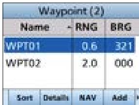
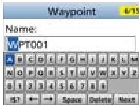
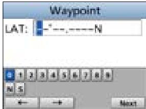
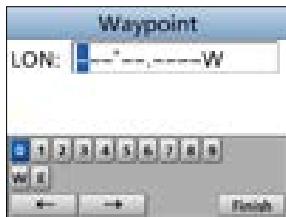
Editing a waypoint
A waypoint's name, latitude, longitude data can be edited.
① You cannot edit the waypoint that is being used for navigation.
- Open the "Waypoint" screen.
[MENU] > Navigation > Waypoint
- Push [] or [] , or rotate [CH/ENT] to select a waypoint.
① Push Sort to sort the waypoints by Name or Range.
- Select Edit
① See steps 3 ~ 9 in “Entering a waypoint” on page 63.
Deleting a waypoint
A waypoint can be deleted from the Waypoint list.
① You cannot delete the waypoint that is now being used for navigation.
- Open the "Waypoint" screen.
[MENU] > Navigation > Waypoint
- Push [] or [] or rotate [CH/ENT] to select a waypoint.
① Push Sort to sort the waypoints by Name or Range. - Push Delete.
- "Delete the Waypoint. Are you sure?" is displayed.
- Push OK.
- The selected waypoint is deleted, and the transceiver returns to the previous screen.
Navigating to a waypoint
The transceiver assists you to navigate to a selected waypoint in the Waypoint list.
① See "Navigation" on page 67 for details.
9 OTHER FUNCTIONS
■ MOB (Man Overboard)
You can enter a Man OverBoard (MOB) waypoint into the transceiver with its GPS position data, as soon as a person has fallen into the water and needs to be rescued. This enables you to reach the MOB location even in the dark, or when you have lost visual contact.
You can select an AIS target during the MOB mode.
Starting MOB
-
Push MOB to enter the MOB mode.
-
Three beeps sound.
- The plotter screen is displayed, and is displayed at your current position on the plotter screen.
① The Arrival and XTE alarms are not detected while in the MOB mode.
TIP: You can also start the MOB mode when you select the "Start MOB" item on the Menu screen.
[MENU] > Navigation > Start MOB
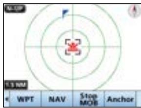
Stopping MOB
- Push Stop MOB to stop the MOB mode.
- "Deactivate MOB. Are you sure?" is displayed.
- Push OK
- disappears, and the transceiver returns to the previous screen.
TIP: You can also stop the MOB mode by selecting the "Stop MOB" item on the Menu screen.
[MENU] > Navigation > Stop MOB
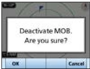
■ Anchor Watch
Anchor Watch is the function to sound an alarm when your vessel is at anchor and has drifted.
Starting Anchor Watch
-
Push Anchor to start the Anchor Watch mode.
-
(a red circle) is displayed as the start position of anchor watch.
- A red dashed is displayed as circle as the range of anchor watch.
TIP: You can also start the Anchor Watch mode by selecting the "Start Anchor Watch" item on the Menu screen.
[MENU] > Navigation > Start Anchor Watch
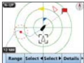
① When your vessel exceeds the range of the anchor watch, "Exceeded anchor radius!" is displayed.
Stopping Anchor Watch
- Push Stop Anchor to stop the Anchor Watch mode.
- "Deactivate anchor watch. Are you sure?" is displayed.
- Push [OK].
- (a red circle) and a red dashed circle disappear.
TIP: You can also stop the Anchor Watch mode by selecting the "Stop MOB" item on the Menu screen.
[MENU] > Navigation > Stop Anchor Watch
9 OTHER FUNCTIONS
Navigation
The transceiver assists you to navigate to a selected destination.
① The function works only when the transceiver is receiving valid GPS signals.
① The function cannot work while in the MOB mode.
NOTE: The Navigation function is a supplemental aid to navigation only, and is not intended to be a substitute for primary navigation equipment.
Starting navigation
There are 3 ways of setting a destination using NAV, selecting in the AIS list, and selecting in the Waypoint list.
NOTE: A popup screen is displayed when the vessel arrives at or near the destination. To stop the function, push any key.
① When the Audible Alarm function is set to "ON," an alarm also sounds. (p. 60)
Using [NAV]:
- Push NAV on the operating screen.
- The "Waypoint" screen is displayed.
-
Push [ ] or [ ] , or rotate [CH/ENT] to select a waypoint.
-
Push Start to start navigation.
-
The plotter screen is displayed, and the transceiver starts to navigate.
-
is displayed on the plotter screen.
-
Push the Software Key for your next operation.
![ICOM IC-M510 - Using [NAV]: - 1](/content/2025/12/344954/images/75ca19725781cc01716f208cf142e19437eca04211a55b92d74afd7956cac470.jpg)
![ICOM IC-M510 - Using [NAV]: - 2](/content/2025/12/344954/images/00cdaede35b36e04364099cff272698296d78455ee323aaed227fe3167ec4e99.jpg)
Selecting in the AIS list:
- Open the list screen.
[MENU] > AIS > Target/Danger/Friends list
- Push [] or [] or rotate [CH/ENT] to select an AIS target.
- Push NAV
"Start navigation. Are you sure?" is displayed.
- Push OK to start navigation.
- The plotter screen is displayed, and the transceiver starts to navigate.
- is displayed on the plotter screen.
TIP: You can also start navigation in the details on the AIS target.
- Repeat steps 1 and 2.
- Push Details, [ENT], or [▶].
- The "Details" screen is displayed.
- Repeat steps 3 and 4.
Selecting in the Waypoint list:
- Open the "Waypoint" screen.
[MENU] > Navigation > Waypoint
- Push [] or [] or rotate [CH/ENT] to select a waypoint.
① Push Sort to sort the waypoints by Name or Range.
- Push NAV.
"Start navigation. Are you sure?" is displayed.
-
Push OK
-
The plotter screen is displayed, and the transceiver starts to navigate to the waypoint.
is displayed on the plotter screen.
TIP: You can also start navigation in the "Detail" screen of the waypoint.
- Repeat steps 1 and 2.
-
Push Details, [ENT], or [CH/ENT].
-
The "Detail" screen is displayed.
-
Repeat steps 3 and 4.
Stopping navigation
- Push Stop NAV to stop navigation.
"Stop navigation. Are you sure?" is displayed. - Push OK
- The transceiver stops to navigate, and then returns to the previous screen.
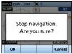
Resetting navigation
The transceiver resets the start position, and restarts navigation from your current position.
① The function works only when the transceiver is receiving valid GPS signals.
① The function cannot work while in the MOB mode, or when the transceiver does not navigate.
- Open the "Navigation" screen.
[MENU] > Navigation
- Push "Reset navigation" to reset the start position.
"Reset navigation. Are you sure?" is displayed. - Push OK
- The transceiver resets the start position, and restarts navigation from your current position.
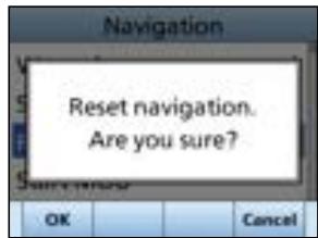
9 OTHER FUNCTIONS
Highway screen
Displays the highway information (only for watching).
Push [DISP] several times to select Highway screen.
① "Navigation OFF" is displayed on the Highway screen when the Navigation mode is not used.
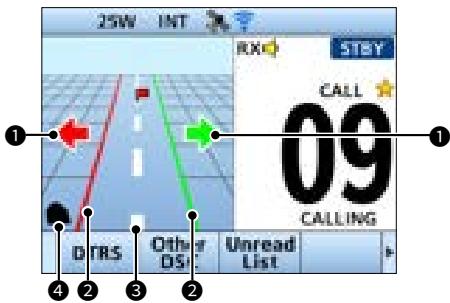
STEERING DIRECTION
Displayed when the vessel crosses the Cross Track Error (XTE) limit line.
XTE LIMIT LINE
Displays the course limit line.
3 NAVIGATION LINE
Displays a line from the start position of navigation to the AIS target or waypoint.
4 YOUR VESSEL ICON
Displayed according to the destination's position.
① When your vessel moves less than 2 knots, ■ is displayed.
Navigation settings
Navigation settings can be customized in "Navigation" on the Menu screen.
[MENU] > Settings > Navigation
Track
- Display
You can select whether or not to display the vessel track on the plotter display.
① The vessel track is recorded, regardless of this setting.
ON: The vessel track is displayed.
OFF: The vessel track is not displayed.
Record
You can select whether or not to save the vessel track.
ON: The vessel track is saved.
OFF: The vessel track is not saved.
- Clear track
You can delete the vessel track.
① When "Clear track. Are you sure?" is displayed, push OK to delete the vessel track.
- Record Reference
You can select the setting to record the vessel track.
Distance: The vessel track is recorded for a fixed distance.
Time: The vessel track is recorded for a fixed period of time.
- Interval (Distance)
Set the distance to record the vessel track to between 0.01 and 6.00 NM (in 0.01 NM steps), when you select "Distance" in the Record reference.
- Interval (Time)
Set the period of time to record the vessel track to between 1 and 60 seconds (in 1 second steps) when you select "Time" in the Record reference.
Anchor watch
Audible Alarm
You can select whether or not to sound an alarm when the vessel arrives at or near the destination.
ON: The alarm sounds.
OFF: The alarm does not sound.
Range
Set the range to between 0.01 and 6.00 NM (in 0.01 NM steps) for the alarm function.
Arrival Alarm
- Audible Alarm
Select whether or not to sound an arrival alarm.
ON: The alarm sounds when the vessel arrives at or near the destination.
OFF: The alarm does not sound.
Range
Set the range to sound an alarm when your vessel arrives at or near the destination to between 0.01 and 6.00 NM (in 0.01 NM steps).
XTE alarm
Audible Alarm
Select whether or not to sound an XTE Alarm.
ON: The alarm sounds when the vessel goes off course.
OFF: The alarm does not sound.
Range
Set the range to sound an alarm when your vessel goes off course to between 0.01 and 6.00 NM (in 0.01 NM steps).
9 OTHER FUNCTIONS
Lost target
A vessel is regarded as a "Lost target" after a specified period of time has passed since the vessel last transmitted data, as described below.
The "Lost target" icon disappears from the plotter display 6 minutes and 40 seconds after the vessel was regarded as a "Lost target." Ask your dealer for details.
The criteria to become a Lost target
Class A/B
| Vessel type | Lost target maximum interval Class A | Lost target maximum interval Class B *1 | ||
| CS *2 | SO*3 | |||
| 1 | Class A: Vessel is at anchor, moored and not moving faster than 3 knotsClass B: Vessel is not moving faster than 2 knots | 1080 seconds | 1080 seconds | |
| 2 | Vessel is at anchor, moored and moving faster than 3 knots | 60 seconds | N/A | |
| 3 | Class A: Vessel is moving between 0 and 14 knotsClass B: Vessel is moving between 2 and 14 knots | 60 seconds | N/A | 180 seconds |
| 4 | Vessel is moving between 0 and 14 knots while changing course | 60 seconds | N/A | |
| 5 | Vessel is moving between 14 and 23 knots | 36 seconds | N/A | 90 seconds |
| 6 | Vessel is moving between 14 and 23 knots while changing course | 36 seconds | N/A | |
| 7 | Vessel is moving faster than 23 knots | 30 seconds | N/A | 30 seconds |
| 8 | Vessel is moving faster than 23 knots while changing course | 30 seconds | N/A | |
| 9 | Vessel is moving faster than 2 knots | N/A | 180 seconds | N/A |
1 AIS Class B does not provide information about the navigational status, anchored or moored.
2 CS: Carrier-sense,
*3 SO: Self organized
- Others
| Category | Lost target maximum interval |
| SAR aircraft | 60 seconds |
| AtoN | 1080 seconds |
| Base station | 60 seconds |
Using the Intercom
The optional Intercom function enables you to communicate between the deck and the cabin. The optional HM-195 COMMANDMICIV™ or an Android/iOS device is required for Intercom operation.
① Connect the HM-195 as described on page 99.
① Download the RS-M500 when you operate by the Android/iOS device.
NOTE: While using the Intercom function,
- Transmit is disabled.
The received call audio is muted. -
Operation is disabled on devices other than the two that are using the Intercom function.
-
Open the "Intercom" screen.
[MENU] > Intercom
- Select the unit, then push [ENT] or [CH/ENT].
- Enters the Intercom mode.
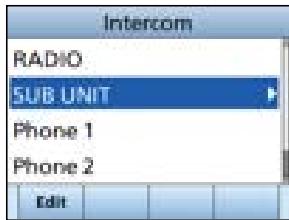
-
Hold down Call to sound the intercom beeps.
-
The transceiver and the command microphone, or the mobile device sound beeps while holding down Call.
- "Call" is displayed.
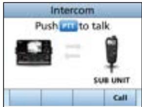
- After releasing Call, hold down [PTT] and speak into the microphone at your normal voice level.
"Talk" is displayed.
① To adjust the transceiver volume level, rotate [VOL].
① To adjust the command microphone's intercom volume level, rotate [VOL/SQL] (Dial) on the command microphone.
- After releasing [PTT], you can hear the response through the speaker.
- Push [CLEAR] to return to the previous screen.
NOTE: While in the Intercom mode, the transmit and receive functions are disabled. When the transceiver is transmitting, the Intercom function is disabled.
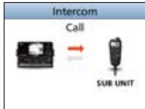
Intercom

Intercom
9 OTHER FUNCTIONS
Using the RX Hailer
The RX Hailer function enables you to hear the received audio on the deck or bridge through a Hailer speaker.
To use this function, the external hailer speaker must be connected to the transceiver.
① Connect an external hailer speaker as described on page 95.
- Push Rx Hailer to enter the RX Hailer mode.
-
Push[▼], then push [▲] or [▶] or rotate [CH/ENT] to set the RX Hailer function ON or OFF.
-
Push[▲], then push [▲] or [▶] or rotate [CH/ENT] to adjust the volume level.
-
To exit the RX hailer mode, push [ENT] or [CH/ENT].
-
The “ � × � × ”icon is displayed when the RX hailer function is set to ON.
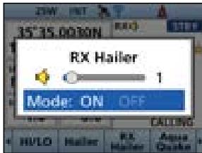
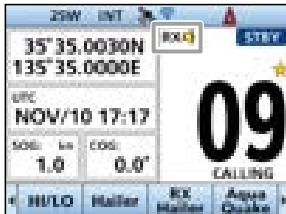
Using the Hailer
You can talk without leaving the bridge by using the 2 way hailer function.
To use this function, the external hailer speaker must be connected to the transceiver.
① Connect an external hailer speaker as described on page 95.
① You cannot transmit while using the hailer.
- Open the "Hailer" screen.
[MENU] > Hailer
-
Hold down [PTT] and speak at your normal voice level.
-
While holding down [PTT], the screen shown on the right is displayed.
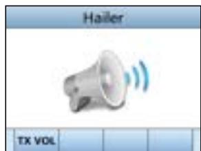
① Push TXVOL to open the volume adjustment screen.
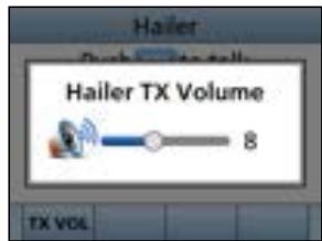
NOTE: While in the hailer mode, the transmit and receive functions are disabled. When the transceiver is transmitting, the hailer function is disabled.
Using the Horn function
Automatic Foghorn function
The Automatic Foghorn function sounds a horn repeatedly until the function is turned OFF.
The foghorn outputs from the hailer speaker. To use this function, the hailer speaker must be connected to the transceiver. See page 95 for connection details.
| TYPE | PATTERN | USAGE | |
| Underway | One 5-second blast every 120 seconds. | 5s 120s | Motor vessel underway and making way. |
| Stop | Two 5-second blasts (separated by 2 seconds) every 120 seconds. | 5s 120s | Motor vessel underway but stopped (not making way). |
| Sail | One 5-second blast followed by two 1-second blasts (each separated by 2 seconds) every 120 seconds. | 5s 120s | Sailing vessel underway, fishing vessel (underway or anchored), vessel not under command, a vessel restricted in her ability to maneuver (underway or at anchor), or a vessel towing or pushing another ahead. |
| Tow | One 5-second blast followed by three 1-second blasts (each separated by 2 seconds) every 120 seconds. | 5s 120s | Vessel under tow (manned). |
- Open the "Auto Foghorn" screen.
[MENU] > Horn > Auto Foghorn
-
Select the foghorn pattern, and then push [ENT] or [CH/ENT] to return to the previous screen.
-
The " "icon is displayed.
① To turn OFF the Auto Foghorn, select "OFF" in the "Auto Foghorn" menu.
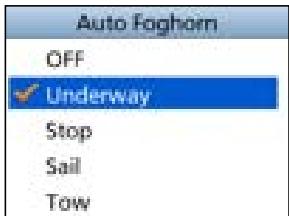
Horn Volume function
- Open the "Horn Volume" screen.
[MENU] > Horn > Horn Volume
- Push [<] or [>, or rotate [CH/ENT] to adjust the foghorn level.
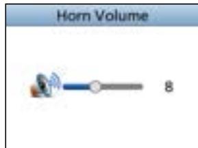
Manual Horn function
- Open the "Manual Horn" screen.
[MENU] > Hom > Manual Horn
-
Hold down Horn to sound a horn.
-
While holding down Horn, the horn sounds, and the screen shown on the right is displayed.
① To adjust the horn volume level, push VOL to open the Horn Volume popup screen.
NOTE: While in the Horn mode, the transmit and receive functions are disabled. When the transceiver is transmitting, the Horn function is disabled.
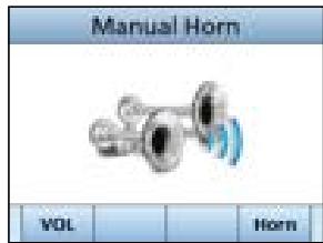
Frequency setting
- Open the Frequency.
[MENU] > Horn > Frequency
- Select the foghorn's audio frequency.
① Available frequency range is 200Hz to 700Hz in 50Hz steps.
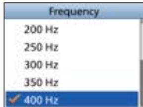
Using the Voice Scrambler
The Voice Scrambler provides private communications. In order to receive or send scrambled transmissions, you must activate the scrambler function. You also need to set the scrambler code on the Menu screen. (p. 85)
① The scrambler function automatically turns OFF when Channel 16 or 70 is selected.
1. Select an operating channel other than Channel 16, 70 or the weather channels.
2. Push Voice SBL to turn the Voice Scrambler ON or OFF.
- The "SBL" icon is displayed when the voice scrambler is ON.
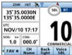
Setting scrambler codes
Set the code to between 1 and 32 on the Menu screen. In order to understand each other, all transceivers in your group must use the same scramble code.
Command microphone operation
You can connect an optional HM-195 COMMAND MICROPHONE to the transceiver. Push DISP to display the Plotter screen or the Highway screen on the command microphone screen.
Plotter screen
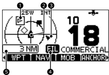
TARGETBOX
2 YOUR VESSEL ICON
① The vessel icon automatically points in the direction your vessel is heading, in 45 degree steps.
① When your vessel moves less than 2 knots per hour, ■ is displayed.
3 TARGET ICONS
| AIS* | AIS target: Vessel |
| AIS* | AIS target: Vessel (Friend) |
| AIS* | AIS target: AIS-SART, AIS-MOB, and EPIRB-AIS |
| AIS* | AIS target: Search and Rescue (SAR) aircraft |
| AIS* | AIS target: Aids to Navigation (AtoN) |
| AIS* | AIS target: Aids to Navigation (AtoN) virtual |
| AIS | AIS target: Base station |
| Waypoint: During navigation. | |
| MOB | |
*Blinks when the AIS target is closer than your CPA and TCPA settings (Danger target).
4 DISPLAY FILTER INDICATOR
Displayed when the type of targets on the plotter screen is filtered.
DISPLAY RANGE
Highway screen
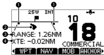
XTE LIMIT LINE
2 YOUR VESSEL ICON
① When your vessel moves less than 2 knots per hour, ■ is displayed.
3 RANGE
Displays the range (RNG) from your vessel to the target.
XTE
Displays the Cross Track Error.
The Software Key names
Some Software Key names in the transceiver and the command microphone are different.
Example:
| Transceiver | Command microphone |
| Target Select | SEL |
| Target Select | SEL |
| Dual Watch | DW |
| Tri Watch | TW |
| DSC Log | LOG |
| Target Details | INFO |
| Voice SBL | SCBL |
| RX Hailer | RX |
| AquaQuake | AQUA |
| FAV ★ | ★ |
| CH Name | NAME |
| Back light | BKLT |
| Disp on Plotter | PLOT |
Command microphone Menu screen items
These items are displayed only on the Command microphone screen. Use the command microphone keys to make the settings.
Display Contrast
[MENU] > Settings > Configuration > Display Contrast
Adjusts the contrast of the Command microphone's display in 8 steps. (Only in the Day Mode)
Soft Keys/Dial assignment
[MENU] > Settings > Configuration > Key Assignment > Soft Keys
[MENU] > Settings > Configuration > Key Assignment > Dial
- Soft Keys assignment
You can assign a desired function to a Software Key. The assigned function can be used when its key icon is displayed on the Command microphone screen.
- Dial assignment
You can assign the audio volume (Volume), squelch (SQL), channel selection (Channel), and the Command microphone backlight level (Backlight) to any one of 4 sequential positions on the Dial. Pushing Dial 1 to 4 times sequentially selects the desired function, and rotating Dial adjusts the level, or selects a value or number.
Example: Dial assignment
- Open the "Dial" screen.
- Select the dial's position, then push [ENT].
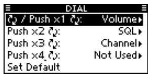
- Select the item to assign, then push [ENT].
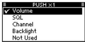
COMMANDMIC Speaker
[MENU] > Settings > Configuration > COMMANDMIC SP
Select the speaker to use when the Command microphone is connected to the transceiver.
Internal Speaker: Outputs audio from a Command microphone's speaker.
External Speaker: Outputs audio from an external speaker connected to a Command microphone.
NOTE: Regardless of this setting, audio is output from the transceiver and the supplied microphone.
10 MENU SCREEN
Using the Menu screen
The Menu screen is used to set items, select options, and so on for the transceiver's functions.
Menu screen operation
Example: Setting the key beep to "OFF."
-
Push [MENU].
-
The Menu screen is displayed.
-
Push [▲] or [▼], or rotate [CH/ENT] to select "Settings," and then push [ENT], [CH/ENT], or [▶].
-
The "Settings" screen is displayed.
① Holding down [▲] or [▼], or rotate [CH/ENT] sequentially scrolls up or down through the Menu screen.
-
Push [] or [] , or rotate [CH/ENT] to select "Configuration," and then push [ENT], [CH/ENT], or [] .
-
The "Configuration" screen is displayed.
-
Push [▲] or [▼], or rotate [CH/ENT] to select "Key Beep," and then push [ENT], [CH/ENT], or [▶].
-
The "Key Beep" screen is displayed.
-
Push [ ] or [ ] , or rotate [CH/ENT] to select "OFF," and then push [ENT] or [CH/ENT].
-
"OFF" is set and the transceiver returns to the previous screen.
TIP:
- To exit the Menu screen, push [MENU].
To return to the previous screen, push [<] or [CLEAR].
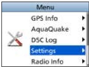
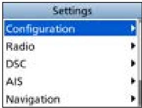
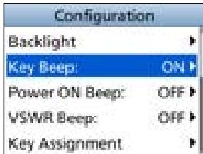
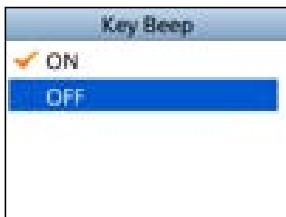
Menu screen items
The Menu screen contains the following items.
See the referred pages for each items.
The displayed menu items may differ, depending on the transceiver version or presetting.
| Menu | Submenu | Item | Reference |
| Distress | - | Nature | p. 21 |
| Position | LAT | p. 20 | |
| LON | |||
| UTC | |||
| Other DSC | - | Msg Type | p. 38 |
| Address | |||
| Category | |||
| Mode | |||
| Channel | p. 20 | ||
| Unread List/Task List *1 | - | - | p. 45 |
| AIS | - | Plotter | p. 51 |
| Target List | p. 55 | ||
| Danger List | |||
| Friends List | |||
| Hailer | - | - | p. 74 |
| Horn | - | Manual Horn | p. 76 |
| Auto Foghorn | p. 75 | ||
| Horn Volume | p. 76 | ||
| Frequency | p. 76 | ||
| Intercom | - | - | p. 72 |
| Navigation | - | Waypoint | p. 62 |
| Stop Navigation | p. 68 | ||
| Reset Navigation | p. 68 | ||
| Start MOB/Stop MOB | p. 65 | ||
| Start Anchor Watch/Stop Anchor Watch | p. 66 | ||
| GPS Info | - | - | p. 82 |
| AquaQuake | - | - | p. 14 |
| DSC Log | - | Received Call Log | p. 43 |
| Transmitted Call Log |
*1 For only the USA version.
10 MENU SCREEN
Menu screen items
| Menu | Submenu | Item | Reference |
| Settings | Configuration | Backlight | p. 82 |
| Display Contrast | p. 78 | ||
| Key Beep | p. 82 | ||
| Power ON Beep | |||
| VSWR Beep | |||
| Key Assignment | p. 83, 78 | ||
| UTC Offset | p. 83 | ||
| Inactivity Timer | |||
| GPS | |||
| Speaker | |||
| COMMANDMIC SP | p. 78 | ||
| RX Hailer | p. 73 | ||
| Noise Cancel | p. 84 | ||
| PWR SW from MIC | |||
| Model *2 | |||
| Radio | Scan Type *3 | p. 85 | |
| Scan Timer *3 | |||
| Dual/Tri-Watch *3 | |||
| Channel Group | |||
| Call Channel | |||
| WX Alert *1 | p. 85 | ||
| Voice Scrambler *4 | |||
| Favorite CH | |||
| FAV on MIC | |||
| Channel Display | |||
| LO/DX | |||
| DSC | Position Input | p. 46 | |
| Individual ID | |||
| Group ID | |||
| Auto ACK | |||
| CH Auto Switch | |||
| DSC Data Output | |||
| Alarm Status | p. 47 | ||
| CH 70 SQL Level | |||
| Self Check Test | |||
| Procedure *1 |
1 For only the USA version.
2 For only the European version.
3 Except for the NLD version.
4 Displayed only when the voice scrambler unit is installed.
| Menu | Submenu | Item | Reference |
| Settings | AIS | North/Course Up | p. 59 |
| Target Display | |||
| CPA/TCPA | |||
| Friends | p. 60 | ||
| ID Blocking | p. 61 | ||
| Navigation | Track | p. 70 | |
| Anchor Watch | |||
| Arrival Alarm | |||
| XTE Alarm | |||
| NMEA | NMEA 0183 | p. 86 | |
| NMEA 2000 | p. 86 | ||
| WLAN | Function | p. 88 | |
| Advanced Settings | p. 90 | ||
| Information | p. 93 | ||
| Radio Info | - | - | p. 87 |
■ Menu items description
GPS Info
Displays your position, date, time, Speed Over Ground (SOG), Course Over Ground (COG), and RAIM* information.
- Only when the built-in GPS receiver is used.
Settings
- Configuration
[MENU] > Settings > Configuration
Backlight
You can adjust the backlight brightness or the Display mode.
Key Beep
You can select whether or not to sound a beep when a key is pushed.
ON: A beep sounds when a key is pushed.
OFF: No beep sounds, for silent operation.
Power ON Beep
You can select whether or not to sound a beep when the transceiver is turned ON.
ON: The transceiver sounds a beep.
OFF: The transceiver does not sound a beep.
VSWR Beep
Select whether or not to sound a beep when a high VSWR is detected.
ON: A beep sounds when a popup screen is displayed.
OFF: No beep sounds when a popup screen is displayed.
10 MENU SCREEN
Settings
Key Assignment
- Soft Key 1~21
You can change which Software Key functions to display, and their order. You can assign up to 21 Software Keys at a time.
① The usable Software Key functions and their order may differ, depending on the transceiver version or presetting.
① Some Software Keys may not be usable, depending on other item settings.
- Set Default
Sets the Software Key function order as default.
① The default setting may differ, depending on the transceiver version or presetting.
UTC Offset
Set the offset time between Universal Time Coordinated (UTC) and your local time to between -14:00 and +14:00 (in 1 minute steps).
Inactivity Timer
The transceiver automatically returns to the operating screen if you push no key for the set period of time for each mode.
Not DSC Related
Setting for when a screen that is not related to DSC is displayed.
DSC Related
Setting for when a screen that is related to DSC is displayed.
Distress Related
Setting for when a screen that is related to a Distress call is displayed.
- RT Related
Setting for when the transceiver is in the Radio Telephone mode.
GPS
Selects a satellite to be used for GPS (Global Positioning System) to pinpoint the geographic location of your transceiver anywhere in the world.
This setting may not be usable, depending on the transceiver version or presetting.
GPS
The GPS (Global Positioning System) is permanently set to ON.
- GLONASS
Selects whether or not to use the data from the GLONASS (GLObal'naya NAvigatsionnaya Sputnikovaya Sistema) satellites.
SBAS
Turns the SBAS (Satellite Based Augmentation System) function ON or OFF.
When turning ON this function, the GPS position accuracy can be improved.
Speaker
Select the speaker to use.
Transceiver and Mic:
The audio is heard from both the internal speaker and the speaker microphone.
Transceiver only:
The audio is heard from only the internal speaker.
RX Hailer
Set the RX Hailer function.
① See page 73 for details.
Noise Cancel
The Noise Cancel function reduces random noise components in the received or transmitted signal. Set the function for both receiving and transmitting.
RX
OFF: The Noise Cancel function is OFF.
Low: Reduces random noise components in the received signal to approximately one half.
Mid: Reduces random noise components in the received signal to approximately one third.
High: Reduces random noise components in the received signal to approximately one tenth.
Radio
Set the reduction level of the Noise Cancel function.
Hailer
Set the reduction level of the Noise Cancel function when the Hailer function is turned ON.
- TX
ON: Reduces random noise components in the transmitted signal to approximately one third.
OFF: The Noise Cancel function is OFF.
- Microphone
Select whether or not to use the Noise Cancel function for the transmit signal.
- COMMANDMIC
Select whether or not to use the Noise Cancel function for the transmit signal when using the optional HM-195 command microphone.
- Mobile Device
Select whether or not to use the Noise Cancel function for the transmit signal when using the RS-M500 mobile device application.
PWR SW from MIC
Select whether or not to turn OFF the transceiver at the same time that you turn OFF the command microphone.
① The optional command microphone is required to use this function.
All Units
When you turn OFF the command microphone, the transceiver is turned OFF at the same time.
- Own Unit
The transceiver is not turned OFF even if you turn OFF the command microphone.
Model
(For only the European version)
Select the country where you operate the transceiver.
① After select the country, "The Settings are reset. Are you sure?" is displayed. Push OK to return to the Configuration screen.
(1) If no country is selected, "General" is automatically selected.
10 MENU SCREEN
Settings
Radio
[MENU] > Settings > Radio
Scan Type
Except for the NLD version) Selects the scan type. The default setting differs, depending on the transceiver version.
① See page 16 for details.
Normal Scan: Scans all Favorite channels in the selected channel group.
Priority Scan: Sequentially scans all Favorite channels, while periodically checking Channel 16.
Scan Timer
(Except for the NLD version) You can use the Scan Timer to pause, or to resume after 5 seconds, when a signal is detected.
ON: When a signal is detected on a channel, the scan pauses for 5 seconds, and then resumes. If the signal disappears in less than 5 seconds, the scan immediately resumes.
OFF: When a signal is detected on a channel, the scan pauses until the signal disappears, and then resumes.
Dual/Tri-Watch
(Except for the NLD version) Select Dualwatch or Tri-Watch. ① See page 18 for details.
Dualwatch: Periodically checks Channel 16 while operating on another channel.
Tri-Watch: Periodically checks Channel 16 and the Call channel while operating on another channel.
Channel Group
Select the suitable channel group for your operating area. Select USA, INT, or CAN, depending on the transceiver version.
① See page 10 for details.
Call Channel
You can change your Call channel. The default setting may differ, depending on the transceiver version.
① See page 13 for details.
WX Alert
For the USA version, an NOAA broadcast station transmits a Weather Alert tone before any important weather information.
① See page 11 for details.
ON with Scan: The preset Weather channels are sequentially checked while scanning.
ON: The previously selected (last used) Weather channel is checked while scanning.
OFF: The Weather Alert tone is not detected.
Voice Scrambler
① Displayed only when a Voice scrambler unit is installed.
- Function
Turn the Voice Scrambler function ON or OFF.
- Codes
Set the Voice Scrambler code to between 1 and 32. In order to understand each other, all transceivers in your group must use the same scramble code, as well as the same scrambler unit.
Favorite CH
You can set all channels as Favorite channels, clear all settings, or reset to default. By default, some channels are preset. The Favorite channels differ, depending on the transceiver version.
① See page 17 for details.
Set All Channels: Sets all channels as Favorite channels.
Clear All Channels: Clears all Favorite channels.
Set Default: Resets Favorite channels to the default.
FAV on MIC
Turn the FAV on MIC function ON or OFF.
ON: Pushing [▲] or [▼] on the supplied microphone scrolls up and down through only the Favorite channels.
OFF: Pushing [▲] or [▼] on the supplied microphone scrolls up and down through all channels.
Channel Display
You can select the number of digits to display the channel number.
① This setting may not be usable, depending on the transceiver version or presetting.
3 digits: The channel number is displayed in 3 digits, such as "01A."
4 digits: The channel number is displayed in 4 digits, such as "1001."
LO/DX
Push to turn the Attenuator function ON or OFF.
Local: The Attenuator function is ON.
Distance: The Attenuator function is OFF.
NMEA
$$ [ M E N U ] > S e t t i n g s > N M E A $$
NMEA 0183
Select the data transfer speed for each port to receive data from external devices.
4800 bps: Select to receive position data from an external GPS receiver.
38400 bps: Select to receive AIS data from an external AIS equipments.
NMEA 2000
NMEA 2000 is a communication standard used to connect various marine devices and display units in the vessel.
The transceiver can easily connect to a NMEA 2000 network with its plug-and-play functionality, and display the information provided from the devices on the network. Select the sensors in NMEA 2000 network which sends data to the transceiver.
① See the next page for the compatible PGN list.
- Open the "NMEA 2000" screen.
- Select the type of data from the menu screen and push [ENT] or [CH/ENT].
- The transceiver starts searching the devices connected to NMEA 2000 network.
① Push Stop Search to stop searching devices and display the device list.
- The list of connected device is displayed.
- Select the device to send the data to the transceiver, and push [ENT] or [CH/ENT].
Device name: The selected device is used.
- Auto: The first device that sends the data to the transceiver or the device that sends a higher priority data is used.
- Not used: No NMEA 2000 device is used.
① Push INFO to display the detail of device.
If another device sends a higher priority data to the transceiver after selecting "Auto," the device to be used will switch to that one. (Except for the AIS data)
① In the "Auto" item, the last connected device information is not saved.
If the transceiver is connected to both NMEA 0183 and NMEA 2000 devices, the NMEA 2000 device has priority. Select "Not Used" if you want to use NMEA 0183 devices.
10 MENU SCREEN
Settings
Compatible PGN list
| Receive | |
| 059392 | ISO Acknowledgment |
| 059904 | ISO Request |
| 060160 | ISO Transport Protocol, Data Transfer |
| 060416 | ISO Transport Protocol, Connection Management |
| 060928 | ISO Address Claim |
| 065240 | ISO Commanded Address |
| 126208 | NMEA |
| 126996 | Product Information |
| 129026 | COG (Course Over Ground) and SOG (Speed Over Ground) - Rapid Update |
| 129029 | GNSS (Global Navigation Satellite System) Position Data |
| 129038 | AIS Class A Position Report |
| 129039 | AIS Class B Position Report |
| 129040 | AIS Class B Extended Position Report |
| 129041 | AIS Aids to Navigation (AtoN) Report |
| 129793 | AIS UTC and Date Report (Base Station) |
| 129794 | AIS Class A Static and Voyage Related Data |
| 129798 | AIS SAR Aircraft Position Report |
| 129809 | AIS Class B “CS” Static Data Report, Part A |
| 129810 | AIS Class B “CS” Static Data Report, Part B |
| Transmit | |
| 059392 | ISO Acknowledgment |
| 059904 | ISO Request |
| 060416 | ISO Transport Protocol, Connection Management |
| 060928 | ISO Address Claim |
| 126208 | NMEA - Acknowledge Group Function |
| 126464 | PGN List |
| 126993 | Heartbeat |
| 126996 | Product Information |
| 126998 | Configuration Information |
| 129026 | COG (course over ground) and SOG (speed over ground) - Rapid Update |
| 129029 | GNSS (Global Navigation Satellite System) Position Data |
| 129038 | AIS Class A Position Report |
| 129039 | AIS Class B Position Report |
| 129040 | AIS Class B Extended Position Report |
| 129041 | AIS Aids to Navigation (AtoN) Report |
| 129545 | GNSS RAIM Output |
| 129793 | AIS UTC and Date Report (Base Station) |
| 129794 | AIS Class A Static and Voyage Related Data |
| 129798 | AIS SAR Aircraft Position Report |
| 129799 | Radio Frequency/Mode/Power |
| 129808 | DSC Call Information |
| 129809 | AIS Class B “CS” Static Data Report, Part A |
| 129810 | AIS Class B “CS” Static Data Report, Part B |
Radio Info
[MENU] > Radio Info
Displays your transceiver's information and command microphone's information as shown below.
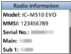
IC-M510/IC-M510E can expand the function by connecting with optional accessories through the wireless LAN (WLAN).
For example, you can use your mobile device as a wireless microphone or the remote controller by installing the RS-M500 REMOTE CONTROL SOFTWARE for Android/iOS and connect it to the IC-M510/IC-M510E.
■Turning the WLAN function ON
- Open the "Function" screen.
[MENU] > Settings > WLAN > Function
-
Push [] or [] , or rotate [CH/ENT] to select "ON," and then push [ENT] or [CH/ENT].
-
"ON" is set, and the transceiver returns to the previous screen.
Setting up the IC-M510/IC-M510E WLAN mode
When connecting to the mobile device, select whether to use the Access Point mode or the Client mode according to your installation environment of the transceiver.
Access Point mode
The IC-M510/IC-M510E works as a wireless LAN access point. In this case, the mobile devices can work by connecting the IC-M510/IC-M510E network.
Normally use the Access Point mode.
① A maximum of 3 mobile devices can be connected to the IC-M510/IC-M510E.
① "TKIP/AES" method is automatically applied for the Access Point mode.
IC-M510/
IC-M510E
RS-M500
Required settings on the IC-M510/IC-M510E Access Point mode
| SSID (Network name) | Default: IC-M510_(8 digit serial number) Example: IC-M510_12345678 |
| Security type | Default: WPA2-PSK/WPA-PSK |
| Password | Default: M510_(8 digit serial number) Example: M510_12345678 |
11 WLAN SETTING
Client mode
The IC-M510/IC-M510E works as a client device in an existing wireless network. In this case, the IC-M510 and your mobile devices must belong to the same wireless network.
① Use the Client mode, if the connection is failed or poor when using the Access Point mode.
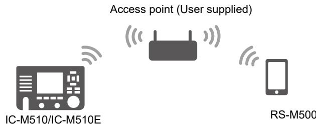
Required information on joining your WLAN
- SSID (Network name)
- Password
① The Security type of the IC-M510/IC-M510E WLAN function is set to WPA2/WPA as default. You may be required to change the Security type or the default gateway settings, depending on your network environment. Ask your network administrator for details on your WLAN settings.
Installation overview
You can connect your mobile device to the IC-M510/IC-M510E through a wireless LAN (WLAN) by the following steps.
Step 1 On the transceiver:
- Turn ON the WLAN function (p. 88).
- Select a WLAN connecting mode, the Access Point mode or the Client mode (pp. 90, 92).
- Enter the required information on configuring the IC-M510/IC-M510E WLAN in the Access Point mode or joining your WLAN in the Client mode.
Step 2 On the mobile device (p. 92):
① The setting procedure depends on the mobile device model or its OS version.
1. Download the RS-M500 to your mobile device.
2. Open the wireless LAN setting screen of your mobile device, and then find the access point name (SSID) that you set to your transceiver.
3. Enter the password, and then join the mobile device to the wireless network.
4. Open the RS-M500 application.
① The RS-M500 automatically searches and connects to the transceiver.
Setting the WLAN in the Access Point mode
- Open the "Configuration" screen.
[MENU] > Settings > WLAN > Advanced Settings > Configuration
-
Select "Access Point."
-
"Access Point Settings" screen is displayed.
① When “Requires reconfigure the phone. Change setting?” is displayed, Push OK. -
Push [▲] or [▼], or rotate [CH/ENT] to select the set items and then push [ENT], [CH/ENT], or [▶]. Set items
SSID: Enter the SSID.
① Up to 32 characters can be entered.
Security: Select the authentication type.
Password: Enter an authentication password of 8 to 63 characters.
① The entered password is masked like as “*”.
Channel: Set to specify the channel by pushing [▲] or [▼].
IP Address: Enter the IP address of the transceiver.
Subnet Mask: Enter the Subnet Mask (the range of the IP addresses used in the network). Enter the IP address and the Subnet Mask to be matched with the network that the mobile device connects to.
TIP:
- Select to enter numbers and letters, and to enter symbols.
- Select number, character or space using [], [], [] , and [] .
- Push [ENT] or [CH/ENT] to enter the selected character.
-
Select “ ” or “ ” on the screen, or rotate [CH/ENT] to move the cursor.
-
After setting the items, push Save
-
The "Advanced Settings" screen is displayed.
① The “” icon is displayed at the top of the screen.
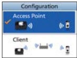
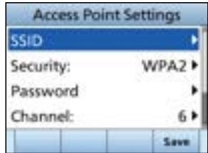
11 WLAN SETTING
Setting the WLAN in the Client mode
- Open the "Configuration" screen.
[MENU] > Settings > WLAN > Advanced Settings > Configuration
- Select "Client."
① When “Requires reconfigure the phone. Change setting?” is displayed, Push OK.
The transceiver starts searching the access point.
- A list of the network device is displayed.
-
Push [] or [] , or rotate [CH/ENT] to select the access point (SSID) and then push [ENT], or [CH/ENT].
-
Select "Auto."
-
The transceiver starts connecting to the access point.
① If you select the "Manual," enter the IP Address and the Subnet Mask.
① If necessary, enter the password. -
"Connection successful." is displayed when the transceiver and the access point are connected.
① When the WLAN connection is successful, the “” icon is displayed at the top of the Standby screen.
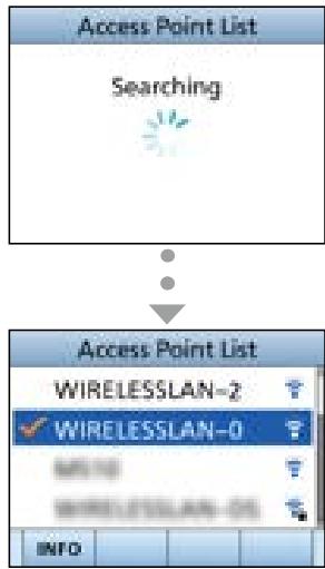
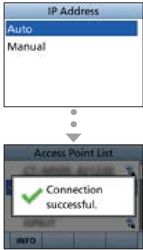
NOTE: The default gateway settings
- When the DHCP server function of the access point is set to "Enable," enter the default gateway IP address.
- When you set your mobile device's IP address as the static IP address, set a default gateway IP address of the mobile device.
Using a mobile device as a microphone
You can use your mobile device as a wireless microphone or the remote controller by installing RS-M500.
① Up to 3 mobile devices can be used as a wireless microphone or remote controller.
① Refer to the RS-M500 manual for details on the RS-M500 operation. The manual can be downloaded from the Icom website: https://www.icomjapan.com/support/
Connecting your mobile device to the transceiver
- Access the Play Store (Android OS) or App Store (iOS), then find and download the RS-M500 to your mobile device.
- Open the wireless LAN setting screen of your mobile device.
- Select the SSID (for example: IC-M510_12345678) you set to your transceiver.
- Enter the password (for example: M510_12345678), and then join the mobile device to the network.
-
Open the RS-M500 application.
-
The RS-M500 automatically searches and connects to the IC-M510/IC-M510E. When the screen shown below is displayed, the RS-M500 is ready to operate.
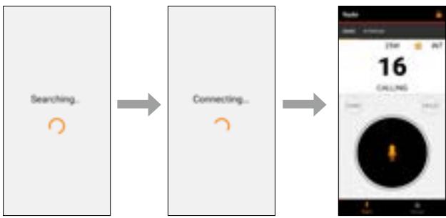
NOTE: If an error message is displayed, check that the WLAN is properly set and connected, the transceiver is turned ON, and then touch "Retry."
Touching "Continue" starts the application without connecting to a transceiver.
- When the connection between the RS-M500 and the IC-M510/IC-M510E is successful, the “ ” icon is displayed at the top of the IC-M510/IC-M510E screen.
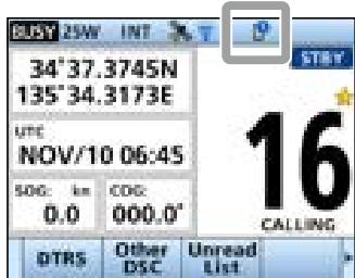
11 WLAN SETTING
NMEA over WLAN settings
You can output the NMEA 0183 (ver. 2.0 or later) sentence through the Wireless LAN (WLAN).
[MENU] > Settings > WLAN > Advanced Settings > NMEA over WLAN
Function
Select whether or not to output the NMEA 0183 sentence to the devices in your WLAN.
Destination IP
Enter the destination IP address.
Destination Port
Enter the destination port number. (Range: 49152 to 65535)
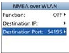
Reset the WLAN settings
- Open the "Advanced Settings" screen.
[MENU] > Settings > WLAN > Advanced Settings
-
Select "Reset WLAN Settings" and then push [ENT], or [CH/ENT].
-
"Requires reconfigure the phone. Reset the WLAN settings?" is displayed.
-
Push OK to reset the transceiver's Advanced Settings.
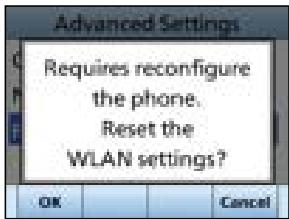
■ WLAN Information
You can confirm the network information for the transceiver.
[MENU] > Settings > WLAN > Information
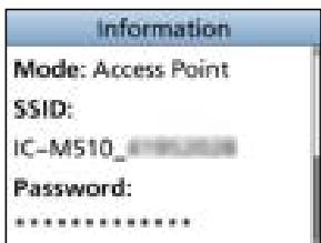
CONNECTIONS AND MAINTENANCE
Supplied accessories
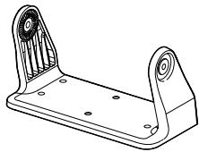
Mounting bracket
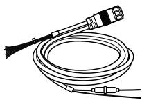
DC power cable
For mounting bracket
Knob bolts
Flat washers (M5)

000
Screws
(5× 20mm)
Spring washers (M5)

Microphone
6 6 6
Microphone hanger
and screws (3× 16mm)
Warning sticker
(For only the USA version)
Flush mount gasket
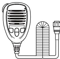


NOTE: Some accessories may not be supplied, or the shape may be different, depending on the transceiver version.
Fuse replacement
One fuse is installed in the supplied DC power cable. If the fuse blows or the transceiver stops functioning, track down the source of the problem, repair it, and replace the damaged fuse with a new one of the proper rating.
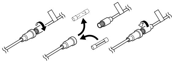
Fuse Coding explanation
Fuse Coding: F 250 V 10 A
Fuse Voltage Rating: 250 Volts
Fuse Current Rating: 10 Amperes
■ Cleaning
If the transceiver becomes dusty or dirty, wipe it clean with a soft cloth.

DO NOT use harsh solvents such as Benzine or alcohol, as they will damage the transceiver's surfaces.
12 CONNECTIONS AND MAINTENANCE
Connections
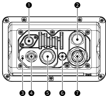
1 ANTENNA CONNECTOR
Connects to a marine VHF antenna with a PL-259 connector.
A key element in the performance of any communication system is the antenna.
Ask your dealer about antennas and the best place to mount them.
CAUTION: Transmitting without an antenna may damage the transceiver.
2 COMMAND MICROPHONE CONNECTOR
Connects the optional command microphone.
3 GROUND TERMINAL
Connects to a vessel ground to prevent electrical shocks and interference from other equipment occurring.
Use a self tapping screw ( 3 × 6 ~mm : not supplied).
NMEA 2000 CONNECTOR
Connects to an NMEA 2000 network.
MICROPHONE CONNECTOR
Connects the supplied or optional microphone.*
- Not usable when the microphone is connected to the connector on the front panel.
GPS ANTENNA CONNECTOR
Connects to an optional GPS antenna.
NOTE:
- The GPS sentences input from this connector takes precedence to over the sentences input from the built-in GPS receiver.
- Be sure the GPS antenna is positioned where it has a clear view to receive signals from satellites, and fixed using the double-sided adhesive pad supplied with the antenna.
7 DC AF/DATA CONNECTOR
Connects the supplied DC power cable.
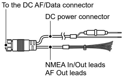
DC POWER CONNECTOR
Connects to a 13.8 V DC power source. (+: Red, -: Black)
NMEA IN/OUT LEADS
Yellow: Listener A (Data-H), Data In (+) Green: Listener B (Data-L), Data In (-) Connects to the NMEA output lines of a GPS receiver for position data.
- NMEA 0183 (ver. 2.0 or later) sentence format RMC, GGA, GNS, GLL and VTG compatible GPS receiver is required. Ask your dealer about suitable GPS receivers.
- The GPS sentences input from this connector are given priority to over the sentences input from the built-in GPS receiver.
- The AIS information through the AIS device inputs as VDM sentence.
① The data communication speed (baud rate) is fixed at 38400 bps. Set the NMEA 0183 item to "38400 bps." (p. 86) - For the versions with the AIS receiver, the external VDM sentence takes precedence over the inputs from the built-in AIS receiver.
White: Talker A (Data-H), Data Out (+) Brown: Talker B (Data-L), Data Out (-) Connects to NMEA 0183 input lines of navigation equipment, to receive position data from other ships.
- An NMEA 0183 (ver. 2.0 or later) sentence format DSC or DSE compatible navigation equipment is required.
- The GPS outputs RMC and GBS format sentences.
- The AIS information through the NMEA 2000 device outputs as VDM sentences.
① The data communication speed (baud rate) is fixed at 38400 bps. Set the NMEA 0183 item to "38400 bps." (p. 86) - For the versions with the AIS receiver, the external VDM sentence takes precedence over the inputs from the built-in AIS receiver.
AF OUT LEADS
Connects to an external speaker or a hailer speaker.
Blue: External Speaker (+)
Black: External Speaker (-)
Orange: Hailer Speaker (+)
Gray: Hailer Speaker (-)
CAUTION: After connecting the DC power connector, NMEA In/Out leads, or AF Out leads, cover the connector and leads with a vulcanizing tape to prevent water seeping into the connection.
12 CONNECTIONS AND MAINTENANCE
Connecting to the MA-510TR
Connect the transceiver to the MA-510TR using the accessory cable. After connecting, an Individual DSC call can be made to the AIS target using the transponder without entering the target's MMSI code. (p. 19)
① See the MA-510TR instruction manual for the connecting instruction.
- Connect each lead to the appropriate lead as follows.
- Listener A (Data-H) (Yellow): To NMEA OUT (+)
- Listener B (Data-L) (Green): To NMEA OUT (-)
- Talker A (Data-H) (White): To NMEA IN (+)
- Talker B (Data-L) (Brown): To NMEA IN (-)
Mounting the transceiver
Using the supplied mounting bracket
You can mount the transceiver on a dashboard using the universal mounting bracket supplied with your transceiver.
CAUTION: KEEP the transceiver and microphone at least 1 meter (3.3 ft) away from the vessel's magnetic navigation compass.
NOTE: The built-in GPS antenna is located, as shown below.
Be sure that the transceiver is positioned where the transceiver has a clear view to receive signal from satellites.
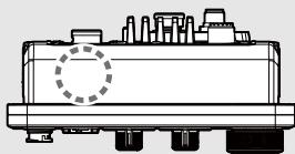
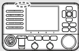
- Mount the bracket securely to a surface which is more than 10mm thick and can support more than 5kg using the 4 supplied screws (5× 20 mm).
NOTE: When mounting the transceiver on a board, fix the bracket to the board using the user supplied bolts and nuts, as shown on the right.
- Attach the transceiver to the bracket so that the face of the transceiver is at 90^ to your line of sight when operating it.
① Adjust the function display angle to be easy-to-read.
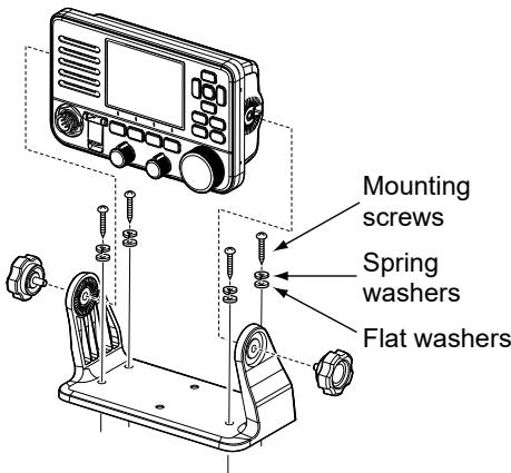
Mounting Example
MBF-7/MBF-9 installation
The optional flush mount kit is for mounting the transceiver to a flat surface (MBF-7: Less than 25 mm thick, MBF-9: Less than 35 mm thick), such as an instrument panel.
① The MBF-7 is used as an example.
NOTE: Install the transceiver and/or microphone more than 1 meter from the vessel's magnetic navigation compass.
- Attach the 2 bolts (5 × 8 ~mm) and spacer supplied with the MBF-7 to both sides of the transceiver.
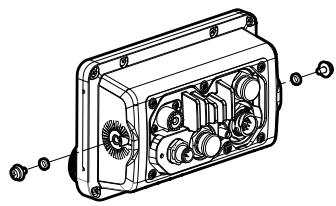
- Using the template on page 114, carefully cut a hole in the instrument panel, or wherever you plan to mount the transceiver.
- Place the flush mount gasket between the transceiver and the instrument panel to prevent water ingress, and slide the transceiver through the hole, as shown on the right.
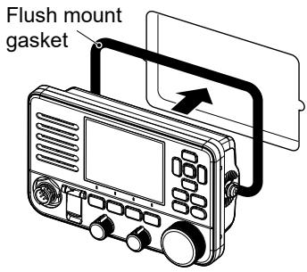
- Fully loosen the locking nut attached to the clamp.
- Insert the clamps between the supplied bolts and the instrument control panel, and then tighten the supplied bolts so that the clamps press firmly against the inside of the instrument control panel. (Torque: 2 N·m)
① Make sure that the clamps align parallel to the transceiver body.
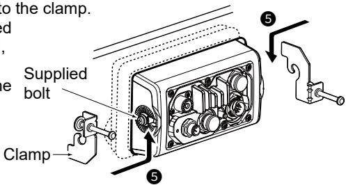
- Tighten the end bolts on the clamps (rotate clockwise).
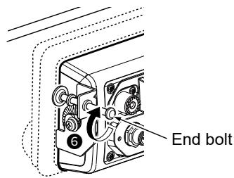
12 CONNECTIONS AND MAINTENANCE
MBF-7/MBF-9 installation
- Tighten the locking nuts (rotate counterclockwise) so that the transceiver is securely mounted in position, as shown on the right. (Torque: 2 N·m)
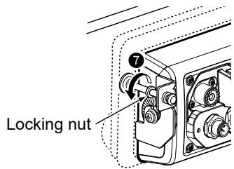
- Connect the antenna and power cable, and then return the instrument control panel to its original place.
Microphone installation
When you use the supplied or optional HM-205RB SPEAKER MICROPHONE, the optional 6 meters long OPC-1000 EXTENSION CABLE can be connected between the transceiver and the HM-205RB to operate from even longer distances.
You can also install the extension cable's connector as a built-in plug on a cabinet or wall.
For the optional HM-195 COMMAND MICROPHONE, you can install the connection cable's connector on the wall in the same way.
① When using the OPC-1541 EXTENSION CABLE to the OPC-1540, connect the OPC-1541 between the OPC-1540 and the transceiver.
NOTE: The firmware of the command microphone may be updated when you connect them to the transceiver.
Installation
- Insert the connection cable connector into the command microphone jack, and tighten the nut.
- To use the cable connector as a wall socket, install it as shown below.
- Using the mounting base as a template, carefully mark the holes where the cable and 3 screws will be fastened.
- Drill holes at these marks.
- Install the mounting base using the supplied screws, as shown below.
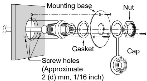
HM-205RB
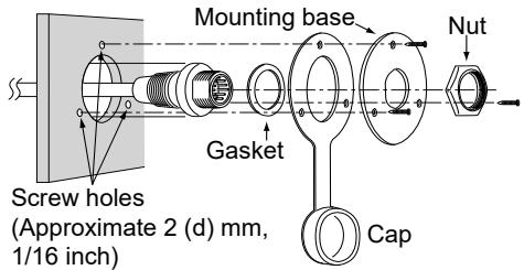
HM-195
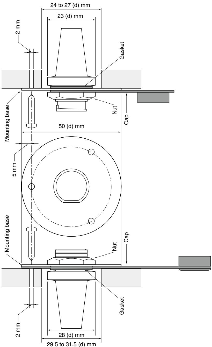
HM-205RB
HM-195
13 SPECIFICATIONS AND OPTIONS
■ Specifications
① All stated specifications are subject to change without notice or obligation.
① Measurements made without an antenna.
IC-M510
General
Frequency coverage:
TX 156.025 ~ 157.425 MHz
RX 156.050 ~ 162.000 MHz
WX CH 161.650 ~ 163.275 MHz
DSC (CH 70) 156.525 MHz
AIS (CH A)* 161.975 MHz
AIS (CH B)* 162.025 MHz
Mode: 16K0G3E (FM), 16K0G2B (DSC), 16K0GXW (AIS)*
- Operating temperature range: -20^ +60^, -4^ +140^
- Current drain (at 13.8 V): TX high (25 W) 5.0 A maximum
RX Maximum audio (at 4 Ω Load)
1.6 A maximum (no external speakers)
2.0 A maximum (with HM-195)
4.0 A maximum (with external speaker)
7.3 A maximum
(with external speaker, RX hailer
speaker, and HM-195 external speaker)
13.8 V DC (11.7 ~ 15.9 V DC)
- Power supply requirement:
Frequency tolerance: - Antenna impedance:
- Dimensions (approximate, projections not included):
Weight (approximate):
Negative ground
±0.5 kHz
50Ω nominal
730 g, 1.6 lb (Not including microphone)
Transmitter
Output power: 25 W or 1 W
Modulation system:
Maximum frequency deviation:
Spurious emissions:
25 W or 1 W
±5 kHz
- Adjacent channel power:
Audio harmonic distortion: - Residual modulation:
Audio frequency response:
Variable reactance frequency modulation
Less than -70 dBc (High Power)
Less than -56 dBc (Low Power)
More than 70 dB
Less than 10% (at 60% Deviation)
More than 40 dB
+1 dB ~ -3 dB of 6 dB octave from 300 Hz ~ 3000 Hz
Receiver
Receive system:
Sensitivity:
Squelch sensitivity:
- Intermodulation rejection ratio:
- Spurious response:
- Adjacent channel selectivity:
Audio output power: - Hum and noise:
Audio frequency response:
Double conversion superheterodyne
FM -10 dBμ (typical) at 12 dB SINAD
DSC (CH 70) -1dB emf (typical) (1% BER)
AIS* -114 dBm (typical) at 20% PER
Less than -7dB
FM More than 75 dB
DSC (CH 70) More than 68dB emf (1%) BER
FM More than 75 dB
DSC (CH 70) More than 73dB emf (1%) BER
FM More than 75 dB
DSC (CH 70) More than 73dB emf (1%) BER
More than 15 W
(at 10% distortion into a 4 external speaker)
More than 40 dB
+1 dB ~ -3 dB of -6 dB octave from 300 Hz ~ 3000 Hz
Built-in GPS
- Channel:
- Deferential satellites:
Corresponding GNSS:
Receiving frequency:
Acquisition, tracking Maximum 24 ch
Calculation Maximum 12 ch
WAAS, EGNOS, MSAS, GAGAN
GPS, GLONASS, SBAS
GPS, SBAS 1575.42 MHz
GLONASS 1602.00 MHz
Wireless LAN
- Wireless LAN standard: IEEE802.11 b/g/n
- Authentication and Encryption: WEP (64/128 bit), WPA-PSK (TKIP), WPA2-PSK (AES)
- Channels: 1 to 13 (2.4 GHz band)
① May differ, depending on the country of use.
Less than 10 mW/MHz
Hailer
Audio output power (at 13.8 V): 25 W typical (at 30% distortion into a 4 Ω)
RX Hailer
-
Audio output power (at 13.8V ): 20 W typical (at 10% distortion into a 4 )
-
Only for the versions with the AIS receiver.
13 SPECIFICATIONS AND OPTIONS
Specifications
IC-M510E
General
Frequency coverage:
TX 156.025 ~ 161.425 MHz
Depending on the version)
RX 156.050 ~ 162.000 MHz
Depending on the version)
DSC (CH 70) 156.525 MHz
AIS (CH A)* 161.975 MHz
AIS (CH B)* 162.025 MHz
16K0G3E (FM), 16K0G2B (DSC, AIS*)
-20^ +60^
TX high (25 W) 5.0 A maximum
RX Maximum audio (at 4 Ω Load)
1.6 A maximum (no external speakers)
2.0 A maximum (with HM-195)
4.0 A maximum (with external speaker)
7.3 A maximum
(with external speaker, RX hailer
speaker, and HM-195 external speaker)
12.0 V DC (10.8 ~ 15.6 V DC)
Mode:
- Operating temperature range:
- Current drain (at 13.8 V):
- Power supply requirement:
- Antenna impedance:
- Dimensions (approximate, projections not included):
Weight (approximate):
Negative ground 12.0 V DC (10.8 ~ 15.6 V DC)
50Ω nominal
175 (W) × 110 (H) × 53 (D) mm
6.9 (W) × 4.3 (H) × 2.1 (D) in
750 g, 1.7 lb (Not including microphone)
Transmitter
Output power:
Modulation system:
Maximum frequency deviation:
Spurious emissions:
Frequency error:
- Adjacent channel power:
Audio harmonic distortion:
- Residual modulation:
Audio frequency response:
25 W or 1 W
Variable reactance frequency modulation
±5kHz
Less than 0.25 W
Less than ± 0.5kHz
More than 70 dB
Less than 10% (at 60% Deviation)
More than 40 dB
+1 dB ~ -3 dB of 6 dB octave from 300 Hz ~ 3000 Hz
Receiver
Receive system:
Sensitivity:
Squelch sensitivity:
- Intermodulation rejection ratio:
- Spurious response:
- Adjacent channel selectivity:
Audio output power: - Hum and noise:
Audio frequency response:
Double conversion superheterodyne
FM -5 dBμ emf (typical) at 20 dB SINAD
DSC (CH 70) -1dB emf (typical) (1% BER)
AIS* -114 dBm (typical) at 20% PER
Less than -2dB emf
FM More than 75 dB
DSC (CH 70) More than 68dB emf (1%) BER
FM More than 75 dB
DSC (CH 70) More than 73dB emf (1%) BER
FM More than 75 dB
DSC (CH 70) More than 73dB emf (1%) BER
15 W typical
(at 10% distortion into a 4 external speaker)
More than 40 dB
+1 dB ~ -3 dB of -6 dB octave from 300 Hz ~ 3000 Hz
Built-in GPS
- Channel:
- Deferential satellites:
Corresponding GNSS:
Receiving frequency:
Acquisition, tracking Maximum 24 ch
Calculation Maximum 12 ch
WAAS, EGNOS, MSAS, GAGAN
GPS, GLONASS, SBAS
GPS, SBAS 1575.42 MHz
GLONASS 1602.00 MHz
Wireless LAN
- Wireless LAN standard: IEEE802.11 b/g/n
- Authentication and Encryption: WEP (64/128 bit), WPA-PSK (TKIP), WPA2-PSK (AES)
- Channels: 1 to 13 (2.4 GHz band)
① May differ, depending on the country of use.
Less than 10 mW/MHz
Hailer
Audio output power (at 13.8 V): 25 W typical (at 30% distortion into a 4 Ω)
RX Hailer
-
Audio output power (at 13.8V ): 20 W typical (at 10% distortion into a 4 )
-
Only for the versions with the AIS receiver.
13 SPECIFICATIONS AND OPTIONS
Dimensions
Unit: mm (inch)
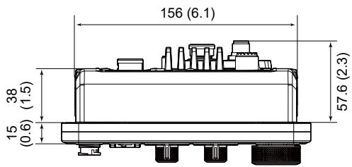
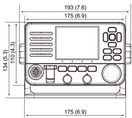
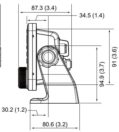
■ Options
NOTE: When an optional product with a lower IP rating than the transceiver is attached, the transceiver meets the lower IP rating of the optional product.
- RS-M500 REMOTE CONTROL SOFTWARE
Android/iOS application that is used to remotely control the transceiver through WLAN. Up to 3 mobile devices can be used as a wireless microphone or remote controller. Intercom function between your mobile device and the transceiver is also available.
- HM-195GB/HM-195GW COMMANDMICIV™
External microphone-type controller. Provides optional intercom operation 6 meters microphone cable and mounting base included.
HM-195GB: Black
HM-195GW: White
- HM-205RB SPEAKER MICROPHONE
Equipped with [] / [] (channel up/down), [H/L], [16/C] and [PTT] keys, a speaker and a microphone.
- OPC-1541 MICROPHONE EXTENSION CABLE
6 meters (20 feet) microphone extension cable for optional HM-195. Up to 2 OPC-1541 can be connected. Usable length is 18 meters (60 feet) maximum.
- OPC-1000 MICROPHONE EXTENSION CABLE
6 meters (20 feet) microphone extension cable for HM-205RB.
- OPC-2522L/OPC-2523L CONVERSION CABLE
L-type conversion cable for a speaker microphone or a command microphone.
OPC-2522L: For HM-205RB
OPC-2523L: For HM-195GB or HM-195GW
- SP-37 HORN SPEAKER
The external horn speaker. Connect with the AF Out leads for the external speaker.
① To use the Hailer function or the Horn function, connect to the transceiver.
① SP-37 has not been tested and Icom does not guarantee its waterproofness.
- UT-112A VOICE SCRAMBLER UNIT
Ensures private communications. 32 codes are selectable. Not available in some countries. Ask your service center or technical dealer for installation details.
UX-241 GNSS ANTENNA
To receive GPS signals.
Cable length: Approximately 5.0 m, 16.4 feet
- MBF-7/MBF-9 FLUSH MOUNT KIT
To mount the transceiver to a panel.
- MBZ-1 FRONT PANEL COVER
Attach to protect from Sun light.
14 TROUBLESHOOTING
Troubleshooting
The transceiver does not turn ON.
- There is a bad connection to the power supply.
→ Check the connection to the transceiver and power supply. (p. 96)
The fuse is blown. Repair the problem, and then replace the fuse. (p. 94)
Little or no sound comes from the speaker.
- The squelch level is set too high. Set the squelch to the threshold point. (p. 12)
The volume level is set too low. Set the volume level to a suitable level. (p. 12)
You cannot transmit with high power.
- Some channels are set for low power or receive only by regulations.
Change channels. (p. 10)
The output power is set to low. Push HlLO to select high power.(p.7)
Scan does not start.
More than 2 favorite channels are not set.
Set at least 2 favorite channels. (p.17)
No beep sounds.
The Key Beep function is OFF. Turn ON the function. (p. 82)
Individual or Group ID cannot be set.
- The entered ID code is incorrect. The first digit must be set to between '1' and '9' for an Individual ID.
Enter a correct ID code. (p. 19)
"??" blinks instead of the position and time.
- Four hours have passed since you manually entered the position.
- The GPS position is invalid. Enter the position and time. (p. 20)
"No Position" and "No Time" are displayed instead of the position and time.
- The GPS signal is not correctly received.
Check the GPS antenna connection and position. (p. 95)
Check the cable connection to NMEA In/Out leads. (p. 96)
Check the transceiver is located where the built-in GPS has a clear view to receive signal from satellites. (p. 97)
The position and time have not been manually entered.
Enter the position and time. (p. 20)
Sensitivity is too low, and only strong signals can be heard.
- The antenna is defective or the coaxial cable connector is shorted or cut. Repair the problem and then reconnect to the antenna connector. (p.95)
Communication cannot be established.
- The antenna is defective or the coaxial cable connector is shorted or cut. Repair the problem and then reconnect to the antenna connector. (p.95)
The transceiver is locked up, and does not respond.
- A software error has occurred.
Turn OFF the transceiver, and then turn it ON again.
The transceiver does not work.
- The transceiver's Phase Lock Loop is unlocked.
Contact your dealer.
The collision alarm does not sound.
- The collision alarm function is OFF.
Turn ON the collision alarm function. (p. 59)
You cannot connect to the mobile devices.
- The WLAN function is OFF.
Turn ON the WLAN function. (p. 88)
SSID is set incorrectly.
Check the SSID on both the transceiver and the access point.
14 TROUBLESHOOTING
Resetting the MMSI code and the ATIS ID
If you need to reset the MMSI code and the ATIS ID*, you must contact Icom and obtain an Activation code.
- For only the German (FRG) and Netherlands (NLD) versions.
Requesting the Activation code
Contact Icom by e-mail with the following information.
(E-mail address: MMSI-reset-request@icom.co.jp)
Required information:
- Model name
- Request code (16-digit number)
① See below how to check the Request code on your transceiver.
Checking your Request code:
You can check the Request code on your transceiver's menu screen.
- Open the "MMSI Clear" screen.
[Menu] > Settings > Configuration > MMSI Clear
① The "MMSI Clear" menu is displayed only when the MMSI code or the ATIS ID has been set.
-
Select "Request Code," and then push [ENT] or [CH/ENT].
-
A 16-digit of Request code is displayed.
① The code on the right is only an example.
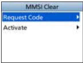
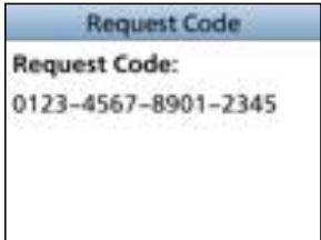
Resetting the MMSI code and the ATIS ID
After Icom accepts your request, you will be sent an Activation code for the reset operation. Enter the Activation code to your transceiver and reset the MMSI code and the ATIS ID.
CAUTION:
- The Activation code can be used only once.
-
The reset operation clears both the MMSI code and the ATIS ID.
-
Open the "MMSI Clear" screen.
[Menu] > Settings > Configuration > MMSI Clear - Select "Activate," and then push [ENT] or [CH/ENT].
- Enter the 16-digit of Activation code.
① The code on the right is only an example.
TIP:
- Select a number using [] and [] .
- Push [ENT] or [CH/ENT] to enter the selected number.
- Select "←" or "→" on the screen or rotate [CH/ENT] to move the cursor.
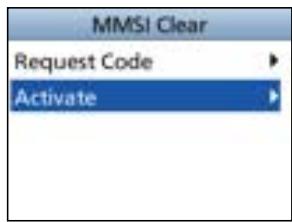


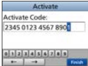
-
Select Finish to set the entered code.
-
When the Activation code is successfully entered, the screen on the right is displayed.
① If the entered code is not correct, an error message is displayed, and then returns to the input screen. Enter the correct Activation code.
Activate Error
- Push OK to clear the MMSI code and ATIS ID.
The transceiver restarts.
NOTE: See page 8 for how to enter your new MMSI code and ATIS ID.
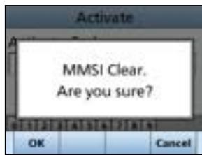
15 CHANNEL LIST
For IC-M510
NOTE: When the "Channel Display" is set to "3 digits" in the Radio setting, the channel number is displayed in 3 digits. See page 86 for details. (For example: "1001" is displayed as "01A.")
| Channel Number | Frequency (MHz) | |||
| USA | INT | CAN | Transmit | Receive |
| 01 | 01 | 156.050 | 160.650 | |
| 1001 | 1001 | 156.050 | 156.050 | |
| 02 | 02 | 156.100 | 160.700 | |
| 03 | 03 | 156.150 | 160.750 | |
| 04 | 156.200 | 160.800 | ||
| 1004 | 156.200 | 156.200 | ||
| 05 | 156.250 | 160.850 | ||
| 1005 | 1005 | 1005 | 156.250 | 156.250 |
| 06 | 06 | 06 | 156.300 | 156.300 |
| 07 | 156.350 | 160.950 | ||
| 1007 | 1007 | 1007 | 156.350 | 156.350 |
| 08 | 08 | 08 | 156.400 | 156.400 |
| 09 | 09 | 09 | 156.450 | 156.450 |
| 10 | 10 | 10 | 156.500 | 156.500 |
| 11 | 11 | 11 | 156.550 | 156.550 |
| 12 | 12 | 12 | 156.600 | 156.600 |
| 13*3 | 13 | 13*1 | 156.650 | 156.650 |
| 14 | 14 | 14 | 156.700 | 156.700 |
| 15*2 | 15*1 | 15*1 | 156.750 | 156.750 |
| 16 | 16 | 16 | 156.800 | 156.800 |
| 17*1 | 17 | 17*1 | 156.850 | 156.850 |
| 18 | 156.900 | 161.500 | ||
| 1018 | 1018 | 1018 | 156.900 | 156.900 |
| 19 | 156.950 | 161.550 | ||
| 1019 | 1019 | 1019 | 156.950 | 156.950 |
| 2019 | RX only | 161.550 | ||
| 20 | 20 | 20*1 | 157.000 | 161.600 |
| 1020 | 1020 | 157.000 | 157.000 | |
| 2020 | RX only | 161.600 | ||
| 21 | 157.050 | 161.650 | ||
| 1021 | 1021 | 1021 | 157.050 | 157.050 |
| 2021 | RX only | 161.650 | ||
| 22 | 157.100 | 161.700 | ||
| 1022 | 1022 | 1022 | 157.100 | 157.100 |
| 23 | 23 | 157.150 | 161.750 | |
| 1023 | 1023 | 157.150 | 157.150 | |
| 2023 | RX only | 161.750 | ||
| 24 | 24 | 157.200 | 161.800 | |
| 25 | 25 | 157.250 | 161.850 | |
| 2025 | RX only | 161.850 | ||
| 26 | 26 | 157.300 | 161.900 | |
| 27 | 27 | 27 | 157.350 | 161.950 |
| 1027 | 157.350 | 157.350 | ||
| 28 | 28 | 28 | 157.400 | 162.000 |
1 Low power only.
^2 RX only.
*3 Momentary High Power.
| Channel Number | Frequency (MHz) | |||
| USA | INT | CAN | Transmit | Receive |
| 1028 | 157.400 | 157.400 | ||
| 2028 | RX only | 162.000 | ||
| 60 | 60 | 156.025 | 160.625 | |
| 61 | 156.075 | 160.675 | ||
| 1061 | 156.075 | 156.075 | ||
| 62 | 156.125 | 160.725 | ||
| 1062 | 156.125 | 156.125 | ||
| 63 | 156.175 | 160.775 | ||
| 1063 | 1063 | 1063 | 156.175 | 156.175 |
| 64 | 64 | 156.225 | 160.825 | |
| 1064 | 156.225 | 156.225 | ||
| 65 | 156.275 | 160.875 | ||
| 1065 | 1065 | 1065*1 | 156.275 | 156.275 |
| 66 | 156.325 | 160.925 | ||
| 1066 | 1066 | 1066*1 | 156.325 | 156.325 |
| 67*3 | 67 | 67 | 156.375 | 156.375 |
| 68 | 68 | 68 | 156.425 | 156.425 |
| 69 | 69 | 69 | 156.475 | 156.475 |
| 71 | 71 | 71 | 156.575 | 156.575 |
| 72 | 72 | 72 | 156.625 | 156.625 |
| 73 | 73 | 73 | 156.675 | 156.675 |
| 74 | 74 | 74 | 156.725 | 156.725 |
| 75*1 | 75*1 | 156.775 | 156.775 | |
| 76*1 | 76*1 | 156.825 | 156.825 | |
| 77*1 | 77 | 77*1 | 156.875 | 156.875 |
| 78 | 156.925 | 161.525 | ||
| 1078 | 1078 | 1078 | 156.925 | 156.925 |
| 2078 | RX only | 161.525 | ||
| 79 | 156.975 | 161.575 | ||
| 1079 | 1079 | 1079 | 156.975 | 156.975 |
| 2079 | RX only | 161.575 | ||
| 80 | 157.025 | 161.625 | ||
| 1080 | 1080 | 1080 | 157.025 | 157.025 |
| 81 | 157.075 | 161.675 | ||
| 1081 | 1081 | 1081 | 157.075 | 157.075 |
| 82 | 157.125 | 161.725 | ||
| 1082 | 1082 | 1082 | 157.125 | 157.125 |
| 83 | 157.175 | 161.775 | ||
| 1083 | 1083 | 1083 | 157.175 | 157.175 |
| 2083 | RX only | 161.775 | ||
| 84 | 84 | 157.225 | 161.825 | |
| 85 | 85 | 157.275 | 161.875 | |
| 86 | 86 | 157.325 | 161.925 | |
| 87 | 87 | 87 | 157.375 | 157.375 |
| 88 | 88 | 88 | 157.425 | 157.425 |
NOTE: Simplex channels, 1021, 1023, 1081, 1082, and 1083 CANNOT be lawfully used by the general public in the USA waters.
1 Low power only.
^2 RX only.
*3 Momentary High Power.
15 CHANNEL LIST
For IC-M510E
NOTE: When the "Channel Display" is set to "3 digits" in the Radio setting, the channel number is displayed in 3 digits. See page 86 for details. (For example: "1001" is displayed as "01A.")
International channels
| CH | Frequency(MHz) | CH | Frequency(MHz) | CH | Frequency(MHz) | CH | Frequency(MHz) | ||||
| Transmit | Receive | Transmit | Receive | Transmit | Receive | Transmit | Receive | ||||
| 01 | 156.050 | 160.650 | 16 | 156.800 | 156.800 | 1037*4 | 157.850 | 157.850 | 75*1 | 156.775 | 156.775 |
| 02 | 156.100 | 160.700 | 17*1 | 156.850 | 156.850 | 60 | 156.025 | 160.625 | 76*1 | 156.825 | 156.825 |
| 03 | 156.150 | 160.750 | 18 | 156.900 | 161.500 | 61 | 156.075 | 160.675 | 77 | 156.875 | 156.875 |
| 04 | 156.200 | 160.800 | 19 | 156.950 | 161.550 | 62 | 156.125 | 160.725 | 78 | 156.925 | 161.525 |
| 05 | 156.250 | 160.850 | 1019*2 | 156.950 | 156.950 | 63 | 156.175 | 160.775 | 1078*2 | 156.925 | 156.925 |
| 06 | 156.300 | 156.300 | 2019*2 | RX Only | 161.550 | 64 | 156.225 | 160.825 | 2078*2 | RX Only | 161.525 |
| 07 | 156.350 | 160.950 | 20 | 157.000 | 161.600 | 65 | 156.275 | 160.875 | 79 | 156.975 | 161.575 |
| 08 | 156.400 | 156.400 | 1020*2 | 157.000 | 157.000 | 66 | 156.325 | 160.925 | 1079*2 | 156.975 | 156.975 |
| 09 | 156.450 | 156.450 | 2020*2 | RX Only | 161.600 | 67 | 156.375 | 156.375 | 2079*2 | RX Only | 161.575 |
| 10 | 156.500 | 156.500 | 21 | 157.050 | 161.650 | 68 | 156.425 | 156.425 | 80 | 157.025 | 161.625 |
| 11 | 156.550 | 156.550 | 22 | 157.100 | 161.700 | 69 | 156.475 | 156.475 | 81 | 157.075 | 161.675 |
| 12 | 156.600 | 156.600 | 23 | 157.150 | 161.750 | 71 | 156.575 | 156.575 | 82 | 157.125 | 161.725 |
| 13 | 156.650 | 156.650 | 1027 | 157.350 | 157.350 | 72 | 156.625 | 156.625 | 83 | 157.175 | 161.775 |
| 14 | 156.700 | 156.700 | 1028 | 157.400 | 157.400 | 73 | 156.675 | 156.675 | 87 | 157.375 | 157.375 |
| 15*1 | 156.750 | 156.750 | 31*1,3 | 157.550 | 162.150 | 74 | 156.725 | 156.725 | 88 | 157.425 | 157.425 |
| P4*5 | 161.425 | 161.425 | |||||||||
1 Low power only.
2 Except for the NLD version.
3 For only the NLD version.
4 For only the NLD and UK versions (UK Marina Channel: M1=1037 (157.850 MHz) for the UK version), and low power only for the NLD version.
*5 UK Marina Channel: M2=P4 (161.425 MHz) for the UK version only.
USA channels (for UK version only)
| CH | Frequency (MHz) | CH | Frequency (MHz) | CH | Frequency (MHz) | CH | Frequency (MHz) | ||||
| Transmit | Receive | Transmit | Receive | Transmit | Receive | Transmit | Receive | ||||
| 1001 | 156.050 | 156.050 | 17*2 | 156.850 | 156.850 | 1037 | 157.850 | 157.850 | 1079 | 156.975 | 156.975 |
| 1005 | 156.250 | 156.250 | 1018 | 156.900 | 156.900 | 1063 | 156.175 | 156.175 | 1080 | 157.025 | 157.025 |
| 06 | 156.300 | 156.300 | 1019 | 156.950 | 156.950 | 1065 | 156.275 | 156.275 | 1081 | 157.075 | 157.075 |
| 1007 | 156.350 | 156.350 | 20 | 157.000 | 161.600 | 1066 | 156.325 | 156.325 | 1082 | 157.125 | 157.125 |
| 08 | 156.400 | 156.400 | 1020 | 157.000 | 157.000 | 67*1 | 156.375 | 156.375 | 1083 | 157.175 | 157.175 |
| 09 | 156.450 | 156.450 | 1021 | 157.050 | 157.050 | 68 | 156.425 | 156.425 | 84 | 157.225 | 161.825 |
| 10 | 156.500 | 156.500 | 1022 | 157.100 | 157.100 | 69 | 156.475 | 156.475 | 85 | 157.275 | 161.875 |
| 11 | 156.550 | 156.550 | 1023 | 157.150 | 157.150 | 71 | 156.575 | 156.575 | 86 | 157.325 | 161.925 |
| 12 | 156.600 | 156.600 | 24 | 157.200 | 161.800 | 72 | 156.625 | 156.625 | 87 | 157.375 | 157.375 |
| 13*1 | 156.650 | 156.650 | 25 | 157.250 | 161.850 | 73 | 156.675 | 156.675 | 88 | 157.425 | 157.425 |
| 14 | 156.700 | 156.700 | 26 | 157.300 | 161.900 | 74 | 156.725 | 156.725 | P4 | 161.425 | 161.425 |
| 15 | RX only | 156.750 | 27 | 157.350 | 161.950 | 77*2 | 156.875 | 156.875 | |||
| 16 | 156.800 | 156.800 | 28 | 157.400 | 162.000 | 1078 | 156.925 | 156.925 | |||
1 Momentary High Power 2 Low power only
① 1037 and P4 channels are UK Marina Channels: M1=1037, M2=P4.
NOTE: Simplex channels, 1021, 1023, 1081, 1082, and 1083 CANNOT be lawfully used by the general public in the USA waters.
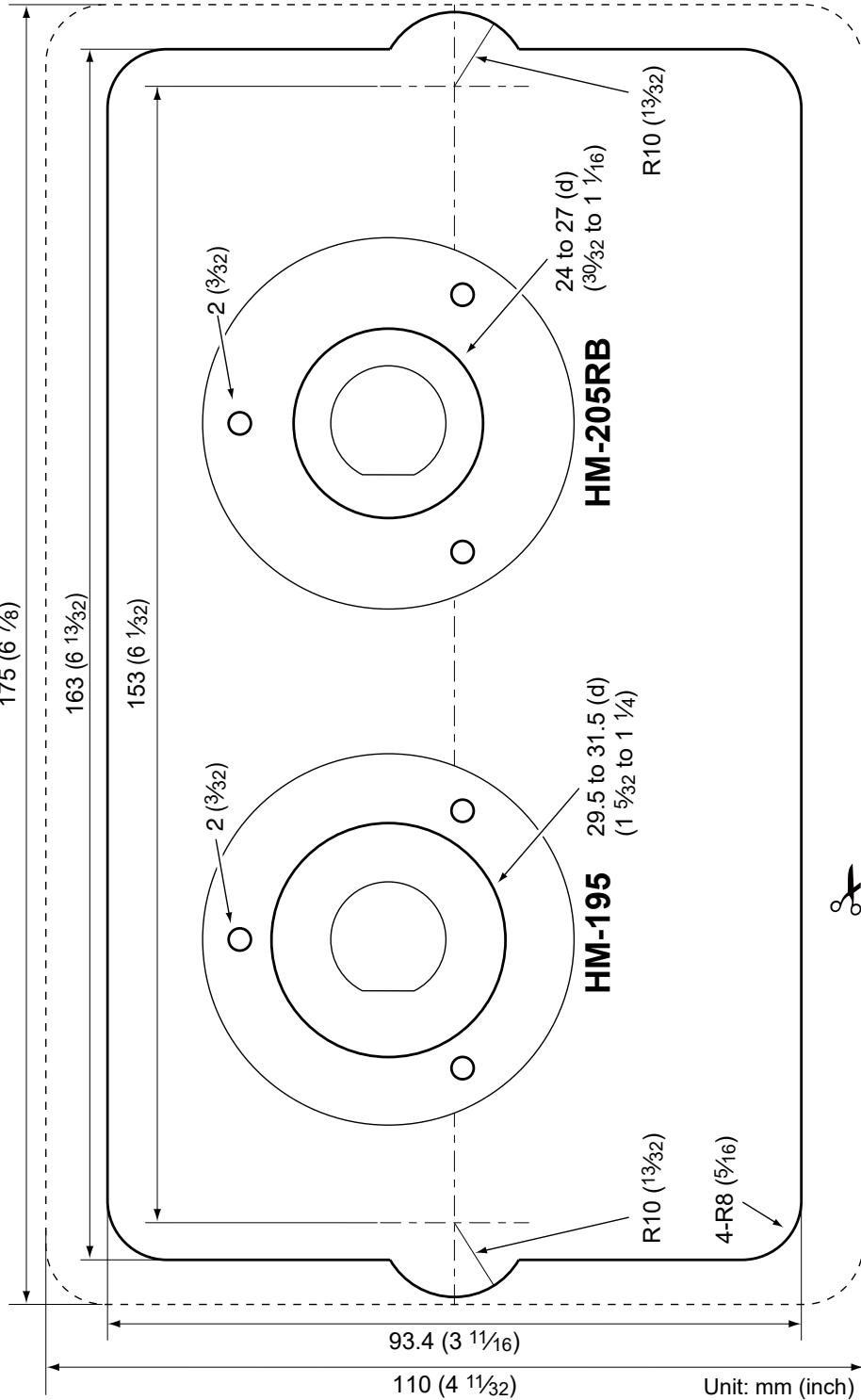
Cut here
A
Accessories
Speaker Microphone..3
Supplied accessories 94
Access Point mode.....88
AIS
About AIS. 50
AIS classes 50
AIS list
Danger list. 55
Friends list. 55
Target list. 55
Using. 54
Alarm Status (DSC Settings)....
All Ships call
Receiving 39
Sending. 27
Anchor Watch
Starting. 66
Stopping. 66
AquaQuake. 14
Auto ACK (DSC Settings) 46
B
Backlight. 12
Configuration. 83
C
Call channel
Radio settings. 85
Selecting 10
Setting. 13
CH 70 SQL Level, DSC
Settings 47
Channel
Channel area .5
Group. 10
Name, editing. 14
Selecting 10
Channel 16. 10
Channel Display
Radio Settings. 86
Channel Group
Radio settings. 85
CH Auto Switch, DSC
Settings 46
Client mode 89
Command microphone
COMMANDMIC
Speaker. 78
Display Contrast....78
Highway screen.....77
Menu screen items..78
Plotter screen. 77
Soft Keys/Dial
assignment.....78
CPA/TCPA
Alarm. 59
Audible Alarm.....59
CPA. 59
Slow Warn. 60
TCPA. 59
D
Detail screen. 57
Distress call
Cancel call 23
Receiving 35
Regular call. 22
Sending. 21
Simple call. 21
Software Key. 23
DSC
Address ID 19
Log, received 43
Log, transmitted ....43
Settings. 46
DSC data output. 46
Dual/Tri-watch
Description 18
Operation 18
Radio settings. 85
F
Favorite CH
Radio Settings.....85
Favorite channels 17
Friend
Alarm. 60
Deleting. 56
Editing. 56
Entering. 56
List 55,60
Front panel 2
Function Display. 4
Fuse replacement.....94
INDEX
G
GPS
Configuration. 83
Group. 10
Group call
Receiving 39
Sending. 28
Group ID
Deleting. 20
DSC setting. 46
H
Hailer 74
Highway
69,77
Horn. 75
1
ID Blocking
Deleting. 61
Editing. 61
Inactivity Timer
Configuration. 83
Individual
Acknowledgment
Sending. 26
Individual call
Receiving 38
Sending. 25
Individual ID
Deleting. 20
DSC Settings 46
Entering. 19
Intercom. 72
K
Key Assignment
Configuration. 83
Key Beep
Configuration. 82
L
License
Operator. 1
Ship Station. 1
Lock function 15
LO/DX
Radio Settings. 86
Lost target. 71
M
MA-510TR
Connecting. 97
Man Overboard (MOB)
Starting. 65
Stopping. 65
MBF-7 installation.....98
MBF-9 installation.....98
Menu screen
Description. 82
Items 80
Using. 79
Microphone
Connecting. 2
MMSI code, entering ....8
Mounting the transceiver
97
Multiple-task mode.....44
N
Navigation
Resetting. 68
Starting. 67
Stopping. 68
NMEA 0183 .86
NMEA 2000
Compatible PGN list..87
NMEA over WLAN......93
Noise Cancel
Configuration.84
North up/Course up.....59
0
Options 106
P
Panel Description 2
Plotter Description 51 Using 51
Polling Reply call, receiving..42 Reply call, sending..34 Request call, sending 31
Position Entering. 20 Input (DSC Settings)
Reply call, receiving..42
Reply call, sending..32 Request call, receiving 40
Request call, sending 31
Power ON Beep Configuration. 82
Power SW from MIC Configuration.84
Procedure (DSC Settings) 47
R
Radio Info. 87
Receiving. 13
RX Hailer 73
Configuration. 83
s
Scan
Priority. 16
Starting. 17
Types 16
Scan Timer
Radio settings.....85
Scan Type
Radio settings.....85
Self Check Test (DSC
Settings) 47
Simple call, Distress call 21
Slow Warn 60
Software Keys 6
Speaker
Configuration. 83
Specifications....101, 103
Squelch level 12
Supplied accessories...94
T
Target Display. 59
Template 114
Test Acknowledgement Receiving 42
Sending. 30
Test call
Receiving 41
Sending. 29
Time, entering. 20
Transmitting. 13
U
UTC Offset
Configuration. 83
V
Voice Scrambler 76
Radio settings.....85
Volume level. 12
VSWR Beep
Configuration. 82
W
Waypoint
Deleting. 64
Editing. 64
Entering. 63
List 62
Navigating 64
Weather Alert. 11
Weather channels.....11
WLAN Information.....93
WLAN Reset. 93
WX Alert
Radio settings.....85