
CX100 ComXpert - Radio test equipment VIAVI - Free user manual and instructions
Find the device manual for free CX100 ComXpert VIAVI in PDF.
| Product Type | Portable Radio Test Equipment |
| Brand | VIAVI |
| Model | CX100 ComXpert |
| Dimensions (approx.) | 280 x 190 x 90 mm |
| Weight (approx.) | 2.8 kg |
| External Power Supply | AC adapter 90-264 VAC, 47-63 Hz, output 12 VDC |
| Internal Battery | Lithium-ion, 7.3 V, 13 Ah |
| Battery Life | Approximately 6 hours (estimated) |
| Connectors | DUPLEX, RF inputs, auxiliary ports |
| Main Functions | Signal analysis, signal generation, communication test, power measurement, etc. |
| Display | Color touchscreen |
| Operating Temperature | 0 °C to +40 °C |
| Maintenance | No user-serviceable parts, maintenance by qualified personnel only |
| Safety | Electrostatic discharge protection, mandatory grounding, do not use with open casing |
| Compliance | Compliant with Industry Canada RSS for license-exempt radio devices |
| Spare Parts and Repairability | VIAVI approved battery (ref. 22071316-002), AC adapter (ref. 22054882); repair by VIAVI only |
| General Information | 280-page manual available for download; device sensitive to ESD |
Frequently Asked Questions - CX100 ComXpert VIAVI
User questions about CX100 ComXpert VIAVI
0 question about this device. Answer the ones you know or ask your own.
Ask a new question about this device
Download the instructions for your Radio test equipment in PDF format for free! Find your manual CX100 ComXpert - VIAVI and take your electronic device back in hand. On this page are published all the documents necessary for the use of your device. CX100 ComXpert by VIAVI.
USER MANUAL CX100 ComXpert VIAVI
The following table contains a record of this manual's revision history.
Table -1 Revision History
| Doc Version | Date | Accepted By |
| Rev 001 | August 22, 2023 | Lance Woods |
| Rev 002 | August 21, 2023 | Robert Facha |
This page intentionally left blank.
Notice
Every effort was made to ensure that the information in this manual was accurate at the time of release. However, information is subject to change without notice, and VIAVI reserves the right to provide an addendum to this manual with information not available at the time that this manual was created.
Copyright/Trademarks
Copyright 2023 VIAVI Solutions, Inc. All rights reserved. No part of this guide may be reproduced or transmitted, electronically or otherwise, without written permission of the publisher. VIAVI Solutions and the VIAVI logo are trademarks of VIAVI Solutions Inc. ("VIAVI").
All other trademarks and registered trademarks are the property of their respective owners.
Patent Information
Patented as described at www.viavisolutions.com/patents
Copyright Release
Reproduction and distribution of this guide is authorized for US Government purposes only.
Terms and conditions
Specifications, terms, and conditions are subject to change without notice. The provision of hardware, services, and/or software are subject to VIAVI's standard terms and conditions, available at www.viavisolutions.com/en/terms-and-conditions
Declaration of Conformity
VIAVI recommends keeping a copy of the Declaration of Conformity that shipped with the unit with the test set at all times.
Warranty Information
Warranty information for this product is available on the VIAVI website at https://www.viavisolutions.com/en-us/warranty-information
Low Voltage Directive Compliance
This product was tested and conforms to the Low Voltage Directive, 73/23/EEC as amended by 93/68/EEC.
Japan Radio Law
The GITEKI Mark can be found on the meter in the "System -> File Browser -> Documents" folder.
Federal Communications Commission (FCC) Notice
This device complies with part 15 of the FCC Rules. Operation is subject to the following two conditions: (1) This device may not cause harmful interference, and (2) this device must accept any interference received, including interference that may cause undesired operation.
This equipment was tested and found to comply with the limits for a Class A digital device, pursuant to Part 15 of the FCC Rules. These limits are designed to provide reasonable protection against harmful interference when the equipment is operated in a commercial environment. This equipment generates, uses, and can radiate radio frequency energy and, if not installed and used in accordance with the instruction manual, may cause harmful interference to radio communications. Operation of this equipment in a residential area is likely to cause harmful interference, in which case you will be required to correct the interference at your own expense.
The authority to operate this equipment is conditioned by the requirements that no modifications be made to the equipment unless the changes or modifications are expressly approved by VIAVI.

ALERT
- To comply with FCC RF Exposure compliance requirements, a separation distance of at least 20~cm must be maintained between the antenna of this device and all persons.
- This transmitter must not be co-located in conjunction with any other antenna or transmitter.
Industry Canada Requirements
This device complies with Industry Canada's license-exempt RSSs. Operation is subject to the following two conditions: 1) This device may not cause interference; and, 2) This device must accept any interference, including interference that may cause undesired operation of the device.
EU WEEE and Battery Directives
This product, and the batteries used to power the product, should not be disposed of as unsorted municipal waste and should be collected separately and disposed of according to your national regulations.
VIAVI has established a take-back processes in compliance with the EU Waste Electrical and Electronic Equipment (WEEE) Directive, 2012/19/EU, and the EU Battery Directive, 2006/66/EC.
Instructions for returning waste equipment and batteries to VIAVI can be found in the WEEE section of VIAVI's Standards and Policies web page
If you have questions concerning disposal of your equipment or batteries, contact the VIAVI WEEE Program Management team at Global. weee@viavisolutions.com
EU REACH
Article 33 of EU REACH regulation (EC) No 1907/2006 requires article suppliers to provide information if a listed Substances of Very High Concern (SVHC) is present in an article above a certain threshold.
For information on the presence of REACH SVHCs in VIAVI products, see the Hazardous Substance Control section of VIAVI's Standards and Policies web page
EU CE Marking Directives (LV, EMC, RoHS, RE)
This product conforms with all applicable CE marking directives. Please see EU Declaration of Conformity for details.
EMC Directive Compliance
This product was tested and conforms to the EMC Directive, 2014/30/EU for electromagnetic compatibility.
UK Declaration of Conformity
This product conforms with all applicable UKCA marking directives. Please request UK Declaration of Conformity for further details.
China RoHS Materials Declaration
The China RoHS Materials Declaration is shipped with the product when required.
California Proposition 65
California Proposition 65, officially known as the Safe Drinking Water and Toxic Enforcement Act of 1986, was enacted in November 1986 with the aim of protecting individuals in the state of California and the state's drinking water and environment from excessive exposure to chemicals known to the state to cause cancer, birth defects or other reproductive harm.
For the VIAVI position statement on the use of Proposition 65 chemicals in VIAVI products, see the Hazardous Substance Control section of VIAVI's Standards and Policies web page
Korea Certification
This manual is a product of the VIAVI Technical Publications Department, issued as part of the CX100 ComXpert Handheld Radio Test Set. The PDF format of this manual is available and distributed with new equipment on a CD-ROM.
The part number associated with the PDF form of this publication is 22144015
The material number associated with the CD-ROM is 22144014
Contact Information
Contact the Technical Assistance Center (TAC) for technical support or with any questions regarding this or other VIAVI products.
Phone: 1-844-GO-VIAVI
- Email: Techsupport.Avcomm@viavisolutions.com
For the latest TAC information, go to:
https://www.viavisolutions.com/support/technical-product-support
Software Notifications
DFARS Statement
If software is for use in the performance of a U.S. Government prime contract or subcontract, software is delivered and licensed as "Commercial Computer Software" as defined in DFAR 252.227-7014 (Feb 2014), or as a "Commercial Item" as defined in FAR 2.101(a) or as "Restricted Computer Software" as defined in FAR 52.227-19 (Dec 2007) or any equivalent agency regulation or contract clause. Use, duplication or disclosure of Software is subject to VIAVI Solutions' standard commercial license terms, and non-DOD Departments and Agencies of the U.S. Government will receive no greater than Restricted Rights as defined in FAR 52.227-19(c)(1-2) (Dec 2007). U.S. Government users will receive no greater than Limited Rights as defined in FAR 52.227-14 (June 1987) or DFAR 252.227-7015 (b)(2) (November 1995), as applicable in any technical data.
Open Source Disclaimer - IMPORTANT READ CAREFULLY
The CX100 ComXpert includes third party software licensed under the terms of separate open source software licenses. By using this software you agree to comply with the terms and conditions of the applicable open source software licenses. Software originated by VIAVI is not subject to third party licenses. Terms of the VIAVI Software License different from applicable third party licenses are offered by VIAVI alone.
This page intentionally left blank.
Safety Information
Symbols and Markings
The following symbols and markings are found on the instrument and in product documentation:
Table 1 Symbols and Markings
| This symbol indicates a NOTE that includes important supplemental information or tips related to the main text. | |
| General Hazard Symbol This symbol represents a general hazard. This symbol may be associated with either a DANGER, WARNING, CAUTION, or ALERT message. See Table 2 for more information. | |
| Toxic Hazard Symbol This symbol indicates a toxic hazard. Item should only be handled by Qualified Service Personnel. Dispense of item in accordance with local regulations. This symbol may be associated with either a DANGER, WARNING, CAUTION, or ALERT message. See Table 2 for more information. | |
| ESD Symbol This symbol indicates an item is sensitive to Electrostatic Discharge (ESD). An item identified as ESD sensitive should only be handled by Qualified Service Personnel. This symbol may be associated with either a DANGER, WARNING, CAUTION, or ALERT message. See Table 2 for more information. | |
| Hot Surface Symbol This symbol represents a hot surface. This symbol may be associated with either a DANGER, WARNING, CAUTION, or ALERT message. See Table 2 for more information. | |
| Hazardous Voltage Symbol This symbol represents hazardous voltages. This symbol may be associated with either a DANGER, WARNING, CAUTION or ALERT message. See Table 2 for more information. | |
| CE Compliant This label indicates item meets the requirements of the applicable European Directives. | |
| WEEE Symbol This symbol indicates the equipment or battery must not be disposed of in a land-fill site or as municipal waste, and should be disposed of according to national regulations. Symbol may be on the equipment, battery, or packaging. |
Safety Definitions
This operation manual uses the following terms to indicate conditions or activities which are potential safety hazards:
Table 2 Safety Definitions
This product is designed and tested to comply with the requirements of IEC/EN61010-1 'Safety requirements for electrical equipment for measurement, control and laboratory use' for Class I portable equipment and is for use in a pollution degree 2 environment.
The equipment is designed to operate from MIL-PRF-2800 Class 2.
When moving the equipment from a cold to hot environment, allow the temperature of the equipment to stabilize before it is connected to the supply to avoid condensation forming. The equipment must only be operated within the environmental conditions specified in the performance data.
This product is not approved for use in hazardous atmospheres or medical applications. If the equipment is to be used in a safety-related application, such as avionics or military applications, the suitability of the product must be assessed and approved for use by a competent person.

WARNING
Operating this device in a manner not specified in accompanying documentation may impair the safety protection built into the device.
Avertissement
- The device casing may become hot to the touch during extended periods of continuous usage
- If bench top operation is not possible, use of temperature resistant gloves is recommended to avoid potential burns
Mise en Garde
- Use only the AC Adapter/Charger supplied with the product. Contact VIAVI for approved replacement parts
- Do not use the AC Adapter/Charger outdoors or in a wet or damp location
- Only connect the AC Adapter/Charger to the correct mains voltage indicated on the ratings label
- Do not use AC Adapter/Charger in temperatures above +40C (104 F) or at altitude above 3000 meters (9842 ft)
Mise en Garde
Approved Part Number: 22054882, Adapter Cord US/NAmerica

CAUTION
- Do not use the power cord if it is damaged or frayed. Replace damaged power cords with cable of the same ratings
- Do not position the power cord in a manner that makes it difficult to disconnect from the main voltage
- Do not allow anything to rest on the power cord
- Do not locate the product where persons can walk on or trip over the power cord
Mise en Garde
Equipment Grounding Protection

CAUTION
- This device is intended to be used with a three wire grounding-type plug while charging
- Failure to use properly grounded power cord/plug may result in electrical shock to personnel or damage to the device
- Do not alter the power cord that is provided with the device
Mise en Garde
Refer to product labeling and safety documentation for maximum input ratings.

CAUTION
Do not overload input connectors. Refer to product Safety and Compliance Specifications or the product data sheet for maximum input ratings.
Mise en Garde
The supply filter contains capacitors that may remain charged after the device is disconnected from the power supply. The residual energy is within the approved safety requirements, however, a slight shock may be felt if the plug pins are touched immediately after removal.
Avertissement
Battery Safety Information
Battery Storage, Handling and Disposal

CAUTION
- To avoid risk of fire and burns, do not tamper with the battery
- Do not open, crush or incinerate the battery
- Do not use or store the battery in temperatures that exceed the manufacturer's specifications
- Follow manufacturer's instructions for battery storage and use
- The battery included with the product is only to be used with the CX100
Mise en Garde
Only replace the battery with the VIAVI approved replacement part. Contact VIAVI for approved replaced parts.
Mise en Garde
Some of the components used in this device may include resins and other materials which give off toxic fumes if incinerated. Dispose of such items appropriately.
Avertissement
Beryllia (beryllium oxide) is used in the construction of some of the components in this equipment.
This material, when in the form of fine dust or vapor and inhaled into the lungs, can cause a respiratory disease. In its solid form, as used here, it can be handled safely, however, avoid handling conditions which promote dust formation by surface abrasion.
Use care when removing and disposing of these components. Do not put them in the general industrial or domestic waste or dispatch them by post. They should be separately and securely packed and clearly identified to show the nature of the hazard and then disposed of in a safe manner by an authorized toxic waste contractor.
Beryllium Copper

CAUTION
Some mechanical components within this instrument are manufactured from beryllium copper. Beryllium copper represents no risk in normal use. The material should not be machined, welded or subjected to any process where heat is involved.
Beryllium copper must NOT be disposed of by incineration. Beryllium copper must be disposed of as "special waste" per local regulations.
Mise en Garde
A Lithium Ion battery is used in this equipment. Lithium is a toxic substance. The following warnings concerning Lithium Ion Batteries must be observed:
- Do not crush, incinerate or dispose of in normal waste
- Do not short circuit or force discharge since this might cause the battery to vent, overheat or explode
Mise en Garde
This device is ESD sensitive and should only be serviced by Qualified Service Personnel.
Mise en Garde
Do not operate this device with the case/cover open. Removing rear cover exposes the operator to surfaces with excessive heat. Opening the case/cover exposes the operator to electrical hazards which can result in damage to the device.
Mise en Garde
This device does not contain user serviceable parts. Servicing should only be performed by Qualified Service Personnel.
Mise en Garde
This product complies with Part 15 of the FCC Rules. Operation is subject to the following two conditions: (1) this product may not cause harmful interferences, and (2) this product must accept any interferences received, including interference that may cause undesired operation.
These limits are designed to provide reasonable protection against harmful interference in a residential installation. This product generates, uses, and can radiate radio frequency energy and, if not installed and used in accordance with the instructions, may cause harmful interference to radio communications. However, there is no guarantee that interference will not occur in a particular installation.
If this product does cause harmful interference to radio or television reception, which can be determined by turning the equipment off and on, the user is encouraged to try to correct the interference by one or more of the following measures:
Reorient or relocate the receiving antenna
- Increase the separation between the equipment and receiver
- Connect the equipment into an outlet on a circuit different from that to which the receiver is connected
- Use properly shielded and grounded cables and connectors in order to meet FCC emission limits

CAUTION
Signal generators can be a source of Electromagnetic Interference (EMI) to communication receivers. Some transmitted signals can cause disruption and interference to communication services out to a distance of several miles. Users of this equipment should scrutinize any operation that results in radiation of a signal (directly or indirectly) and should take necessary precautions to avoid potential communication interference problems.
Mise en Garde
Revision History. R-1
Software Notifications 1-v
Chapter 1 Overview of the CX100 1-1
1.1 About the CX100 ComXpert 1-2
1.2 Device Features and Capabilities 1-3
1.2.1 CX100 RF Features and Capabilities 1-3
1.2.2 OneExpert Platform and System Features 1-4
1.3 Principles of Operation 1-4
1.3.1 OneExpert Platform Overview 1-4
1.3.2 RF Application Module 1-5
1.3.3 Device Software. 1-5
1.4 Front Panel Controls 1-5
1.4.1 LCD 1-6
1.4.2 Function Keys 1-6
1.4.3 Arrow Buttons 1-6
1.4.4 OK Button 1-6
1.4.5 Back Button 1-6
1.4.6 Home Button 1-6
1.4.7 Utility Tray Button. 1-6
1.4.8 Power Button 1-7
1.5 CX100 Connectors 1-7
1.5.1 DUPLEX Connector. 1-8
1.5.2 ANT/SWR Connector. 1-8
1.5.3 10 MHz Frequency Reference I/O Connector 1-9
1.5.4 Audio In Connector 1-9
1.5.5 Audio Out Connector 1-9
1.5.6 USB-C Type Connector 1-9
1.5.7 USB Connector 1-9
1.5.8 Ethernet Connector 1-10
1.5.9 DC Input Connector 1-10
1.6 LED Indicators 1-12
1.6.1 Sync LED 1-12
1.6.2 Network LED 1-12
1.6.3 Error LED 1-13
1.6.4 Battery LED 1-13
1.6.5 Charge Status LED 1-13
Chapter 2 Getting Started: Setup and Operation 2-1
2.1 Upon Receipt 2-2
2.1.1 Unpack the Equipment. 2-2
2.1.2 Inspect the Equipment 2-2
2.1.3 Verify Contents 2-3
2.1.4 Prepare for First Time Use 2-4
2.1.5 Verify Operation 2-5
2.2 Powering the Device 2-6
2.2.1 AC Power Operation 2-6
2.2.2 Battery Operation 2-7
2.3 Power On/Off Procedures 2-7
2.3.1 Turning the Device ON. 2-7
2.3.2 Turning the Device OFF 2-8
2.4 Device Control and Operation 2-8
2.4.1 Local Operation 2-8
2.4.2 Remote Operation 2-8
2.5 UI Navigation, Control and Layout 2-8
2.5.1 Screen Navigation and Control 2-9
2.5.2 Soft-keys 2-10
2.5.3 Selecting Functions and Applications 2-11
2.5.4 Screen Layout 2-12
2.5.5 System Status UI Indicators 2-14
Chapter 3 System and Utility Function Descriptions. 3-1
3.1 Introduction 3-3
3.1.1 Accessing System Settings 3-3
3.1.2 Date and Time Panel 3-4
3.1.3 Remote Operation Panel 3-5
3.1.4 Wireless Personal Area Network (WPAN) Settings Panel 3-6
3.1.5 International Settings Panel 3-6
3.1.6 Network Software Update panel 3-7
3.1.7 USB Software Update Panel 3-8
3.1.8 Hardware & Software Revisions Panel 3-9
3.1.9 Software Options Panel 3-9
3.1.10 Hardware Options Panel 3-9
3.1.11 Calibration Screen 3-10
3.1.12 Home Screen Settings 3-10
3.1.13 Save Location Settings 3-10
3.1.14 Restore Factory Defaults Settings 3-11
3.1.15 Power Off Screen 3-11
3.1.16 Template Management Screen 3-11
3.1.17 Screen & Power Management 3-12
3.1.18 Sounds Screen 3-12
3.1.19 Theme 3-12
3.1.20 User Information 3-13
3.1.21 Help 3-13
3.1.22 Notifications.. 3-13
3.1.23 System Network Screen 3-13
3.1.24 Web Browser 3-17
3.1.25 File Browser 3-17
3.1.26 USB File Browser 3-18
3.2 Utility Functions 3-19
3.2.1 Accessing Utility Functions 3-19
3.2.2 Save Report Button 3-19
3.2.3 View Report 3-20
3.2.4 Screen Shot. 3-20
3.2.5 Network Button 3-20
3.2.6 Wireless Personal Area Network (WPAN)® Button 3-20
3.2.7 Volume Button 3-20
3.2.8 Help 3-20
3.2.9 Tutorial 3-21
3.2.10 Workflow Manager 3-21
3.2.11 Templates 3-21
Chapter 4 Configuring System Settings 4-1
4.1 Locating Device's Unit ID 4-2
4.2 Configuring Device Settings 4-2
4.2.1 Restore Factory Defaults 4-2
4.2.2 Configuring International Settings 4-3
4.2.3 Setting Date and Time 4-4
4.2.4 Change Display Content and Settings 4-6
4.2.5 Configure Device Power Settings 4-7
4.2.6 User Information 4-7
4.2.7 Specifying File Save Location 4-8
4.2.8 Setting the Volume. 4-8
4.3 Configuring 10 MHz Frequency Reference 4-9
4.4 Establishing a Network Connection 4-10
4.4.1 Establishing an Ethernet Connection 4-10
4.4.2 Establishing a WiFi Connection 4-13
4.5 Remotely Operating the Device 4-16
4.5.1 Establishing VNC Viewer Connection 4-16
4.5.2 Ending a Remote Operation Session 4-17
4.6 Establishing a Wireless Personal Area Network (WPAN) Connection 4-17
4.6.1 Enabling Wireless Personal Area Network (WPAN) Connectivity 4-17
4.6.2 Connecting to a Wireless Personal Area Network (WPAN) Device 4-17
4.7 Updating the Device's Software 4-18
4.7.1 Software Availability 4-18
4.7.2 Methods of Updating Software 4-18
4.8 Hardware/Software Versions and Options 4-20
4.8.1 Viewing Hardware/Software Revision Information 4-20
4.8.2 Viewing Option Information 4-20
4.8.3 Installing Options 4-20
4.9 Capturing a Screen Shot 4-21
4.10 Enabling Password Protection 4-21
4.11 Creating UI Shortcut 4-21
4.12 Customizing the Web Browser 4-22
Chapter 5 RF Instrument Function Descriptions 5-1
5.1 Overview of the RF Instrument 5-2
5.2 RF Test. 5-3
5.2.1 RF Test Modes of Operation 5-3
5.2.2 Test Setup Summary Panel 5-4
5.2.3 RF Generator 5-5
5.2.4 Modulation Generator 5-7
5.2.5 RF Receiver 5-10
5.2.6 AF Function Generator. 5-14
5.2.7 RF Test Meters 5-16
5.2.8 Digital Plots Panel 5-30
5.2.9 RF Analyzer 5-32
5.2.10 AF Analyzer 5-43
5.3 Spectrum Analyzer 5-50
5.3.1 Introduction 5-50
5.3.2 Spectrum Analyzer Screen Layout. 5-50
5.4 VSWR/DTF 5-59
5.4.1 Introduction 5-59
5.4.2 VSWR/DTF Screen Layout and Behavior 5-59
5.4.3 VSWR Test Function 5-59
5.4.4 DTF Test Function 5-64
5.4.5 Cable Database (DB). 5-68
5.5 Autotest Function 5-71
5.5.1 Autotest Screen Layout 5-71
5.5.2 Autotest Soft-key Panel 5-72
5.5.3 Autotest Controls and Settings 5-73
5.5.4 Automated Self Test. 5-73
5.6 SCA Capability. 5-75
5.6.1 Launch SCA Autotest. 5-75
5.6.2 SCA Controls and Settings 5-75
5.7 Settings 5-76
5.7.1 Frequency Reference 5-76
Chapter 6 Performing Tests and Measurements 6-1
6.1 CX100 Self Test Procedure 6-2
6.1.1 Scope of Test 6-2
6.1.2 Equipment Needed 6-2
6.1.3 Running Self-test 6-2
6.2 FM Transmitter Testing 6-3
6.2.1 Scope of Test 6-3
6.2.2 UUT Parameters/Characteristics 6-3
6.2.3 Equipment Needed 6-4
6.2.4 Test Setup 6-4
6.2.5 Gathering Test Data 6-8
6.3 AM Transmitter Testing 6-10
6.3.1 Scope of Test 6-10
6.3.2 UUT Parameters/Characteristics 6-10
6.3.3 Equipment Needed 6-10
6.3.4 Test Setup 6-11
6.3.5 Gather Test Data 6-15
6.3.6 Test UUT Power and Frequency 6-15
6.3.7 Test UUT Modulation Level and Distortion 6-15
6.4 FM Receiver Performance Tests 6-16
6.4.1 Scope of Test 6-16
6.4.2 UUT Parameters/Characteristics 6-16
6.4.3 Equipment Needed 6-16
6.4.4 Test Setup 6-17
6.4.5 Configure the CX100 Meters 6-19
6.4.6 Gather Test Data 6-21
6.5 AM Receiver Tests 6-22
6.5.1 Scope of Test 6-22
6.5.2 UUT Parameters/Characteristics 6-22
6.5.3 Required Equipment 6-22
6.5.4 Configuring the Equipment 6-23
6.5.5 Configure CX100 Meters 6-25
6.5.6 Gather Test Data 6-27
6.6 Performing VSWR/DTF Testing 6-28
6.6.1 Scope of Test 6-28
6.6.2 UUT Parameters/Characteristics 6-28
6.6.3 Equipment Needed 6-28
6.6.4 Calibrate the CX100 Before VSWR Testing 6-28
6.6.5 To Perform VSWR Test 6-30
6.7 Performing Distance to Fault (DTF) Tests 6-31
6.7.1 Scope of Test 6-31
6.7.2 UUT Parameters/Characteristics 6-31
6.7.3 Equipment Needed 6-31
6.7.4 Configuring the Equipment. 6-32
Chapter 7 Managing Files and Reports 7-1
7.1 Generating Reports 7-2
7.1.1 Custom Report Fields 7-2
7.1.2 Enforcing Report Entry 7-3
7.1.3 Saving a Report 7-3
7.1.4 Viewing a Report 7-4
7.2 Managing Files. 7-4
7.2.1 Accessing the File Browser 7-4
7.2.2 Selecting Files or Folders.. 7-5
7.2.3 Opening Files or Folders 7-5
7.2.4 Copying and Pasting Files or Folders 7-5
7.2.5 Downloading Files via Web Browser 7-6
7.2.6 Uploading Files Using FTP/HTTP 7-6
7.3 Viewing the User's Guide on the Device 7-6
Chapter 8 Care, Maintenance, and Troubleshooting 8-1
8.1 Recharging the Battery 8-2
8.2 Replacing the Battery. 8-2
8.3 Storing the Module 8-2
8.4 Shipping Instructions 8-2
8.4.1 Return Material Authorization (RMA) 8-3
8.4.2 Tagging the Device. 8-3
8.4.3 Shipping Containers. 8-3
8.4.4 Freight Costs 8-3
8.4.5 Packing Procedure. 8-4
8.5 Operator Level Maintenance 8-5
8.5.1 Visual Inspections 8-5
8.5.2 External Cleaning 8-5
8.5.3 Updating Software 8-6
8.5.4 CX100 ComXpert Self Test Procedure 8-6
8.6 Troubleshooting 8-7
8.6.1 Troubleshooting Symptom Index 8-7
8.6.2 Troubleshooting Procedures 8-8
Appendix A Specifications A-1
A.1 RF Generator Specifications A-2
A.2 Modulation Generator Specifications. A-3
A.3 Audio Frequency (AF) Function Generator Specifications 2
A.4 RF Receiver Specifications A-5
A.5 Measurement Specifications A-6
A.5.1 RF Power Measurement Specifications. A-6
A.5.2 RF Counter Specifications. A-6
A.5.3 FM Measurement Specifications A-7
A.5.4 AM Measurement Specifications A-7
A.5.5 Distortion Measurement Specifications A-7
A.5.6 SINAD Measurement Specifications A-8
A.5.7 Signal to Noise (SNR) Measurement Specifications A-8
A.5.8 AF Counter Specifications A-8
A.6 AF Analyzer Specifications A-9
A.6.1 Frequency Domain Specifications A-9
A.6.2 Time Domain Specifications A-10
A.7 VSWR and DTF Measurement Specifications. A-10
A.8 Audio Filter Specifications A-11
A.9 RF Analyzer Specifications A-11
A.10 Spectrum Analyzer Specifications A-12
A.11 Zero-Span Analyzer Specifications A-13
A.12 Connector Specifications. A-13
A.13 Frequency Standard and Timebase Specifications . A-15
A.14 Power Specifications . A-16
A.15 Hardware Specifications A-16
A.16 Environmental Specifications A-17
A.17 Safety and Compliance Standards A-18
Appendix B Module and Battery Replacement Procedures. B-1
B.1 Intended Audience. B-2
B.2 Battery Replacement Information B-2
B.3 Tool Requirements. B-2
B.4 Safety Information B-2
B.4.1 ESD Precautions B-2
B.4.2 Battery Handling and Disposal. B-3
B.5 Removing the RF Module B-4
B.6 Installing the RF Module B-6
B.7 Removing the Battery B-7
B.8 Installing the Battery B-7
Appendix C DTF Cable DB - Cable Values C-1
Appendix D Keyboard Mapping. D-1
List of Figures
Figure
Title
Page#
Figure 1-1 . CX100 ComXpert Handheld Radio Test Set. 1-2
Figure 1-2 . CX100 Controls and Buttons. 1-5
Figure 1-3 . CX100 RF Input/Output Connectors 1-7
Figure 1-4 . Platform Controls and Connectors 1-9
Figure 1-5 . DC Input Connector Location 1-11
Figure 1-6 . CX100 Front Panel LEDs 1-12
Figure 1-7 . CX100 Battery LED. 1-13
Figure 2-1 Test Screen Layout Examples 2-12
Figure 2-2 . Home Screen Example 2-12
Figure 3-1 . System Settings Menu Access 3-3
Figure 3-2 . CX100 Utility Tray - Example. 3-19
Figure 5-1 . RF Test Mode Menus 5-3
Figure 5-2 . RF Test Setup Summary Panel 5-4
Figure 5-3 .Meter "Block" Content Diagram. 5-16
Figure 5-4 . Opening Meter Configuration Window. 5-17
Figure 5-5 . VSA Block Diagram. 5-24
Figure 5-6 . RF Analyzer Panel Layout. 5-32
Figure 5-7 . RF Analyzer Marker Controls 5-39
Figure 5-8 Identifying Marker Data Fields. 5-40
Figure 5-9 .Marker Indicator Line - Drag and Drop 5-42
Figure 5-10 . . AF Analyzer Frequency Domain Tab Layout. 5-43
Figure 5-11 . . AF Analyzer Time Domain Tab Layout 5-47
Figure 5-12 . Spectrum Analyzer Screen Layout 5-50
Figure 5-13 . VSWR Screen Components 5-60
Figure 5-14 . DTF Tab Layout 5-64
Figure 5-15 . . Cable DB tab Components 5-68
Figure 5-16 . . AutoTest Screen Layout and Functions 5-71
Figure 6-1 .FM Transmitter Test Setup Diagram 6-4
Figure 6-2 . . . AM Transmitter Test Setup Diagram 6-11
Figure 6-3 . FM Receiver Test Setup Diagram 6-17
Figure 6-4 .AM Receiver Test - Setup Diagram 6-23
Figure 6-5 . VSWR Calibration Setup Diagram. 6-28
Figure 6-6 . . . Calibration running and complete 6-29
Figure 6-7 . VSWR Test Setup Diagram 6-30
Figure 6-8 . DTF Test Setup Diagram 6-32
Figure 6-9 . DTF (Distance to Fault) and Calibration 6-33
Figure 6-10 . Return Loss 6-34
Figure B-1 . . RF Module Removal Process Diagrams . B-4
Figure B-2 . . Separating RF Module and Base. B-5
Figure B-3 . . . Base Unit - RF Module Removed 1
Figure B-4 . CX100 RF Module Installation Diagram 6
Figure B-5 . Battery Cover Screw Location. B-7
Figure B-6 . . Battery Cables and Release Clip. B-7
List of Tables
Table
Table Title
Page #
Table E-1. Revision History
Table 1 . Symbols and Markings vii
Table 2 . Safety Definitions VIII
Table 1 . Text and Symbol Conventions .
Table 2-1. Standard Items 2-3
Table 2-2. CX100Accessory Kit #TBD. 2-3
Table 2-3. Types of Softkeys 2-10
Table 2-4. System Status UI Indicators 2-14
Table 3-1. . Date and Time Controls and Settings.. 3-4
Table 3-2. Remote Operation and VNC Controls and Settings 3-5
Table 3-3...... Wireless Personal Area Network Controls and Settings. 3-6
Table 3-4.... Network Software Update Controls and Settings 3-7
Table 3-5.... USB Software Update Controls and Settings. 3-8
Table 3-6. Hardware & Software Revision Data 3-9
Table 3-7 .... Software Options Controls and Settings. 3-9
Table 3-8. Save Location Settings 3-10
Table 3-9. .Restore Defaults Settings.. 3-11
Table 3-10.... Screen and Power Management Settings 3-12
Table 3-11.... Network Controls and Settings. 3-14
Table 3-12.......IPv4/IPv6 Dual Stack Network Controls and Settings. 3-15
Table 3-13. .IPv4 Network Controls and Settings.. 3-15
Table 3-14.......IPv6 Network Controls and Settings. 3-16
Table 5-1. RF Generator Controls and Settings. 5-5
Table 5-2. Modulation Generator Controls and Settings 5-7
Table 5-3. . External Modulation Controls and Settings. 5-9
Table 5-4 . RF Receiver Controls and Settings. 5-10
Table 5-5 . . . AF Generator Controls and Settings. 5-14
Table 5-6 .Meter Limit Status Indicators. 5-18
Table 5-7 Audio Meter Controls and Settings 5-21
Table 5-8 . Demod Meter Controls and Settings 5-22
Table 5-9 Digital Meter General Settings. 5-25
Table 5-10 Digital Meter Modulation Settings 5-26
Table 5-11 Digital Meter Equalizer Settings 5-26
Table 5-12 . Digital Measurement Filter Settings. 5-27
Table 5-13 . Equalizer Soft-key Panel 5-28
Table 5-14 . RF Power Meter Controls and Settings. 5-29
Table 5-15 Constellation Plot Soft-key Panel 5-30
Table 5-16 . Constellation Plot Controls and Settings. 5-31
Table 5-17 . RF Analyzer Softkeys. 5-33
Table 5-18 . RF Analyzer Display Settings 5-34
Table 5-19 . RF Analyzer Instrument Settings. 5-36
Table 5-20 . RF Analyzer Marker Controls and Settings 5-39
Table 5-21 . Marker Data Field Description. 5-40
Table 5-22 . . . AF Analyzer Frequency Domain Softkeys 5-44
Table 5-23 . Frequency Domain Instrument Settings 5-45
Table 5-24 . . . AF Analyzer Time Domain Softkeys 5-48
Table 5-25 . . . AF Analyzer Time Domain Instrument Settings. 5-48
Table 5-26 . Spectrum Analyzer Softkeys 5-51
Table 5-27 . Spectrum Analyzer Display Settings 5-52
Table 5-28 . Spectrum Analyzer Instrument Settings 5-54
Table 5-29 . VSWR Softkeys 5-61
Table 5-30 . VSWR Display Settings. 5-62
Table 5-31 . VSWR Instrument Settings 5-63
Table 5-32 DTF Softkeys 5-65
Table 5-33 DTF Instrument Settings 5-66
Table 5-34 Cable DB Softkeys. 5-69
Table 5-35 Cable DB Controls and Settings 5-69
Table 5-36 .... Autotest Softkeys 5-72
Table 5-37 .... Autotest Controls and Settings 5-73
Table 5-38 . Frequency Reference Controls/Settings 5-76
Table 6-1 . FM Transmitter Test - UUT Settings 6-3
Table 6-2 . FM Transmitter Test - RF Receiver Settings 6-5
Table 6-3 . FM Transmitter Test - AF Function Generator Settings. 6-7
Table 6-4 .AM Transmitter Test - UUT Settings 6-10
Table 6-5 . CX100 Settings - RF Receiver Settings 6-11
Table 6-6 . . . . . AM Transmitter Test - AF Function Generator Settings. 6-13
Table 6-7 . FM Receiver Test - UUT Parameters. 6-16
Table 6-8 . CX100 Settings - RF Generator Settings 6-17
Table 6-9 . FM Receiver Test- Modulation Generator Settings 6-18
Table 6-10 . FM Receiver Test - Meter Settings 6-19
Table 6-11 .... AM Receiver Test - UUT Parameters 6-22
Table 6-12 . . . AM Receiver Test - RF Generator Settings. 6-23
Table 6-13 . . . . AM Receiver Test - Modulation Generator Settings 6-24
Table 6-14 .AM Receiver Test - Meter Settings 6-25
Table 6-15 . VSWR Test - Example Cable Characteristics 6-28
Table 6-16 . CX100 VSWR Test Settings 6-30
Table 6-17.... DTF Test - Example Cable Characteristics 6-31
Table 6-18.... DTF Test Settings 6-32
Table A-1. RF Generator Specifications. A-2
Table A-2. Modulation Generators A-3
Table A-3. . AF Function Generator . A-4
Table A-4 . RF Receiver Specifications . A-5
Table A-5. RF Power Meter Specifications. A-6
Table A-6. RF Counter Specifications. A-6
Table A-7 . FM Measurement Specifications . A-7
Table A-8. .AM Measurement Specifications.. A-7
Table A-9. Distortion Meter Specifications .A-7
Table A-10 . SINAD Meter Specifications . A-8
Table A-11 . . . SNR Meter Specifications . . . . . . . . . . . . . . . . . . . . . . . . . . . . . . . . . . . . . . . . . . . . . .
Table A-12 . . . AF Counter Specifications. A-8
Table A-13 . . . AF Analyzer Frequency Domain . . . . . . . . . . . . . . . . . . . . . . . . . . . . . . . . .
Table A-14 . . . AF Analyzer Time Domain. A-10
Table A-15 . VSWR/DTF Specifications) . A-10
Table A-16 Audio Filters. A-11
Table A-17 . RF Analyzer Specifications . A-11
Table A-18 . Spectrum Analyzer Specifications. A-12
Table A-19 .... Zero Span Analyzer Specifications .. A-13
Table A-20 . ANT/SWR Connector Specifications . A-13
Table A-21.... DUPLEX Connector Specifications. A-14
Table A-22 Audio In Connector Specifications. A-14
Table A-23 Audio Out Connector Specifications .A-14
Table A-24 .... Ethernet Connector Specifications . . . . . . . . . . . . . . . . . . . . . . . . . . . . . . . . . . . . . . . . . . . . . . . . . . . . . .
Table A-25....USB Connector Specifications .A-15
Table A-26 . DC Input Connector Specifications . A-15
Table A-27 . Frequency Standard I/O A-15
Table A-28 . . . Power Specification. A-16
Table A-29 . Battery Specifications . A-16
Table A-30 .Dimensions and Weight.
Table A-31 . Environmental Specifications A-17
Table A-32 . Miscellaneous Standards A-18
Table B-1 . Battery Replacement Tool Requirements . B-2
Table C-1. RG-115A Cable Values C-1
Table C-2. RG-142B Cable Values C-1
Table C-3. RG-174 Cable Values C-1
Table C-4. RG-213 Cable Values C-2
Table C-5. RG-214 Cable Values C-2
Table C-6. RG-223 Cable Values C-2
Table C-7. RG-400 Cable Values C-2
Table C-8. RG-55 Cable Values C-2
Table C-9. RG-55A Cable Values C-2
Table C-10. RG-55B Cable Values C-3
Table C-11 .RG-58 Cable Values C-3
Table C-12. RG-58A Cable Values C-3
Table C-13. RG-58B Cable Values C-3
Table C-14. RG-58C Cable Values. C-3
Table C-15. RG-58foam Cable Values C-3
Table C-16. RG-8 Cable Values C-4
Table C-17 . RG-8A Cable Values C-4
Table C-18. RG-8foam Cable Values C-4
Table C-19....USER Cable Values C-4
Table D-1. Computer to CX100 Keyboard Mapping . D-1
Preface
This preface contains the following product information:
• Intended Audience
Product Nomenclature .ii
Related Information
- Contact Information .iii
Conventions. iii
Purpose and Scope
This document contains safety information and instructions for installing and operating the CX100 ComXpert Handheld Radio Test Set.
| Type of Manual: | Operation Manual |
| Equipment Name and Model Number: | CX100 ComXpert Handheld Radio Test Set |
| Purpose of Equipment: | CX100 ComXpert is used for testing radios and related equipment. |
Intended Audience
This manual is intended for personnel who are familiar with radio test systems and associated equipment and terminology.
Product Nomenclature
| Common Name | Official Nomenclature |
| CX100 | CX100 ComXpert Handheld Radio Test Set |
| OneExpert | OneExpert™ Platform |
Terminology
The terms CX100 and device are used throughout this manual to refer to the CX100 ComXpert.
The term OneExpert and OneExpert base are used throughout this manual to refer to the OneExpert™ Platform base unit.
Related Information
This is the operation manual for the CX100 ComXpert Handheld Radio Test Set. This manual contains product safety information, specifications, setup procedures, and detailed descriptions of CX100 functions.
This manual is distributed with new products on a CD-ROM. Check the VIAVI website for availability of this and other product publications.
Contact Information
Contact the Technical Assistance Center (TAC) for technical support or with any questions regarding this or another VIAVI products.
Phone: 1-844-GO-VIAVI
For the latest TAC information, go to:
http://www.viavisolutions.com/en/services-and-support/support/technical-assistance
Conventions
This guide uses typographical and symbols conventions as described in the following table.
Table 1 Text and Symbol Conventions
| Item(s) | Example(s) |
| Buttons, keys, switches, or connectors on the device (hardware components). | Press the On button. Press the Enter key. Flip the Power switch to the on position. |
| Buttons, links, menus, menu options, tabs, or fields on a UI (software components). | Click Start. Click File > Properties. Click the Properties tab. Type the name of the probe in the Probe Name field. |
| References to external publications appear in this typeface. | See Newton's Telecom Dictionary. |
| Text that must be entered exactly as shown. | Type a: \set.exe in the dialog box. |
| A vertical bar | means “or”: only one option can appear in a single command. | platform a | b | c |
This page intentionally left blank.
Overview of the CX100
This chapter describes CX100 ComXpert controls, connectors, functions and capabilities. This chapter reviews the following topics:
About the CX100 ComXpert 1-2
Device Features and Capabilities 1-3
Principles of Operation. 1-4
- Front Panel Controls 1-5
CX100 Connectors. 1-7
LED Indicators 1-12
1.1 About the CX100 ComXpert
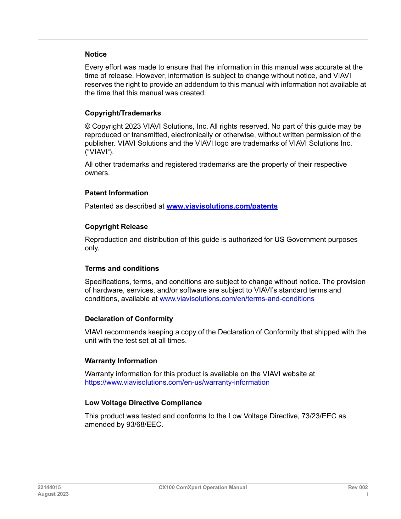
The CX100 ComXpert is a hand-held communications test set that supports bench and field radio testing. The CX100 provides the capabilities needed to test a variety of radios, as well as commercial radio applications. The CX100 is capable of performing high power measurements, as well as fault finding for antennas, power amplifiers and interconnects.
The CX100 ComXpert is powered by an internal, rechargeable battery that provides up to 3 hours of continuous operation. The CX100 is equipped with a DC input connector that supports battery charging and use of an AC power adapter for connection to an AC power supply.
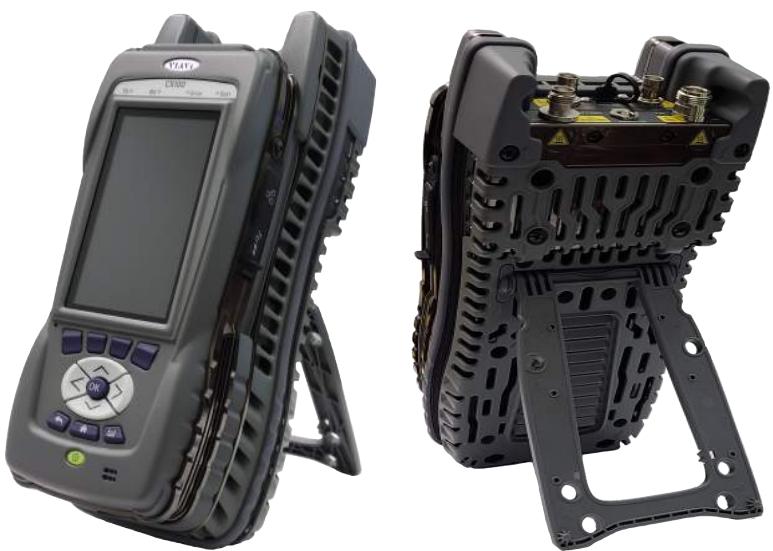
Figure 1-1 CX100 ComXpert Handheld Radio Test Set
The CX100 ComXpert uses the VIAVI OneExpert Platform to support system functions such as network connectivity, power management and software updates. The RF Application Module supports the device's RF test and measurement functions.
The CX100 ComXpert is designed for ease of use, reliability and long service life. The modular platform design allows the base platform to be expanded to incorporate other application modules which may be developed to support continuing industry advancements.
1.2 Device Features and Capabilities
This section identifies key features and capabilities supported by the CX100 ComXpert.
1.2.1 CX100 RF Features and Capabilities
The CX100 provides test and measurement capabilities that can be used to evaluate the transmit and receive performance of a radio system (radio, antenna, base station), locate faults in antennas, power amplifiers and cables. The CX100 supports the following test and measurement capabilities:
1 MHz to 6 GHz frequency range with up to 100 MHz instantaneous bandwidth
- Measurement limit checks, user selectable measurement types (maximum, minimum, live and average) for all meters
Built-in-Test (BIT) and diagnostics for internal validation and testing
- Capable of receiving and recording RF signals for off-line analysis or playback
RF Spectrum Analyzer supports up to 6 GHz frequency with 20 MHz instantaneous bandwidth
- Asynchronous, swept RF Analyzer
Audio Analyzer supports DC up to 100 kHz with spectral and scope displays.
- Digital signal analyzer with EVM and constellation measurements
Frequency and Amplitude modulation meters
Frequency Counter and Frequency Error meters
RF Power Meter supports 20 W continuous; 200 W with an external attenuator
Parametric Distortion and SINAD meters
AM/FM/PM modulation and demodulation
VSWR and DTF measurements
- Two internal Audio Frequency (AF) Function Generators
- Two internal Modulation Generators; one External Modulation Generator
- Self-Test and Diagnostics for internal validation and testing
- Remote access and operation using VNC viewing application
Dedicated high power RF output port and high power RF input port
Dedicated high sensitivity, low power RF input port and low RF output port
- Fast tuning speed and wide range of Resolution Bandwidth (RBW) allowing high accuracy analysis
1.2.2 OneExpert Platform and System Features
The OneExpert platform supports the following hardware and system features:
- Rechargeable battery supports 3 hours continuous use
- Capacitive Liquid Crystal Display (LCD) with user adjustable back-light and contrast
Field upgradeable software and option installation
One Ethernet connector
One 3.0 USB connector
WiFi and GPS (timing) receivers - Sleep mode (battery power saving mode)
1.3 Principles of Operation
The CX100 ComXpert uses the VIAVI OneExpert platform to support system functionality, and the RF Application Module as the basis for RF test and measurement functions.
1.3.1 OneExpert Platform Overview
The VIAVI OneExpert platform base contains a processor, backplane interface, Liquid Crystal Display (LCD), front panel controls, and a rechargeable battery. The base processor is responsible for managing system level functions such as network connectivity, file management and software upgrade procedures. The base processor is also responsible for managing the device's power consumption/power saving functions and the device's battery charging processes.
The LCD and front panel controls provide the user interface for controlling and operating the device. The mechanical components of the OneExpert base provide access to the device's USB and Ethernet ports as well as the DC Input port. The backplane provides the interface between the OneExpert base unit and RF Application Module.
1.3.2 RF Application Module
The CX100's RF Application Module supports the device's RF test and measurement functions. The RF Application Module's mechanical housing contains the device's RF and audio input and output connectors. The RF Application Module contains a PCB Assembly that is responsible for processing and routing signals through the module.
1.3.3 Device Software
The CX100 ships from the factory with the current version of Software (SW) and Firmware (FW) installed on the device. The Hardware & Software Revisions Panel displays the version of the software and firmware installed on the device. See section 3.1.8, "Hardware & Software Revisions Panel", on page 3-9 for information.
Routine maintenance checks should be performed to ensure the device has been upgraded to the latest production software release. See section 4.7, "Updating the Device's Software", on page 4-18 for software upgrade procedures. In the event a software update is needed, CX100 software can be upgraded in the field, and can be updated using a network connection or a USB device. CX100 software also supports field-installed software options.
1.4 Front Panel Controls
Front panel controls and buttons are used to operate and control the device. Many of the functions performed using the front panel buttons are supported using the touchscreen.
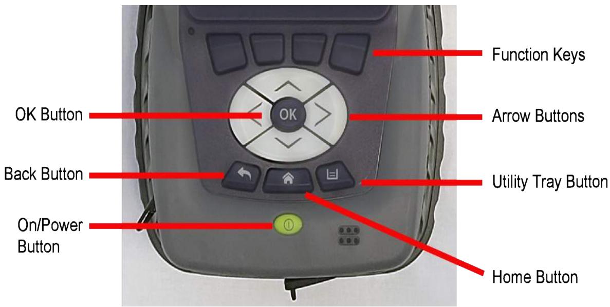
Figure 1-2 CX100 Controls and Buttons
1.4.1 LCD
The Liquid Crystal Display (LCD) is a capacitive touchscreen that operates similarly to a mobile device. The touchscreen supports gestures such as press to open/select/activate, press and hold, press and drag, swipe sideways and pinch to zoom.
1.4.2 Function Keys
The Function Keys select functions or UI content associated with each key position. When there are soft-keys located on the UI above the Function Keys, the soft-keys and corresponding hard key will perform the same function.
1.4.3 Arrow Buttons
The Arrow buttons are used to navigate through menu selections and fields on the UI.
1.4.4 OK Button
The OK button is used to accept/confirm a changed setting or to proceed to the next menu. Use the Back button to close a menu or exit a data field without changing the current setting.
1.4.5 Back Button

The Back button is used to exit a menu or to go back to the previous menu or content. If a data field is selected for editing, selecting the Back button exits the data field, canceling an unconfirmed change.
1.4.6 Home Button

Pressing the Home button returns to the device's main/home screen. The UI Home button performs the same action.
1.4.7 Utility Tray Button

Pressing the Utility Tray button opens a panel on the UI that is referred to as the Utility Tray. The Utility Tray contains buttons that access functions to save test reports, turn network or Wireless Personal Area Network (WPAN) functions on or off, or enable/disable remote operation.

The Utility Tray can also be opened using the Tray soft-key located at the top of the UI.
See section 3.2, "Utility Functions", on page 3-19 for additional information.
1.4.8 Power Button
The Power Button is used to turn the device on and off. The device is turned on or off by pressing and holding the button for approximately 3 seconds.

NOTE
The CX100 can be configured to emit a beep at power up/power down. See section 4.2.5.2, "Beep at Power Up/Down", on page 4-7) for information.
1.5 CX100 Connectors
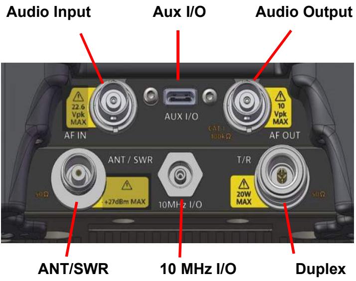
Figure 1-3 CX100 RF Input/Output Connectors

CAUTION
Do not overload input connectors. Refer to product specifications or the product data sheet for maximum input ratings.
Mise en Garde
The DUPLEX connector is a combined (duplex) N-type connector. This connector is selectable as the RF Generator output and/or the RF Receiver input connector.
DUPLEX Input Connector
The DUplex connector should be selected as the RF Input connector when performing high power measurements.
DUPLEX Output Connector
The DUPLEX connector should be selected as the RF output connector when the lowest level of RF Generator output is needed.
1.5.2 ANT/SWR Connector
The ANT/SWR connector is a TNC connector and is selectable as either an RF Input or RF Output connector.

NOTE
The ANT/SWR connector does not support duplex input/output capabilities. When the ANT/SWR connector is selected as the RF output connector, the system disables the connector's receive capabilities.
ANT/SWR as Input Connector
The ANT/SWR connector should be selected as the RF Input connector for the following test conditions:
To perform over the air testing using an external antenna.
- When test parameters require maximum input sensitivity.
- When measuring low level RF signals.
ANT/SWR as Output Connector
The ANT/SWR connector should be selected as the RF output connector for the following test conditions:
- To output high power RF signals.
VSWR/DTF testing.
1.5.3 10 MHz Frequency Reference I/O Connector
The 10 MHz Frequency Reference I/O connector is a SMB connector and is used to connect the CX100 to an external frequency standard, or to output the internal frequency standard from the CX100 to other equipment.
The 10 MHz frequency reference is configured from the Frequency Reference Configuration window. See section 4.3, "Configuring 10 MHz Frequency Reference", on page 4-9 for setup information.
1.5.4 Audio In Connector
The Audio In connector is a BNC type connector that serves as the RF Instrument's primary AF, Digital and external modulation input connector. The Audio In connector is selected on the AF Analyzer panel.
1.5.5 Audio Out Connector
The Audio Out connector is a BNC type connector that serves as the RF Instrument's primary AF generator and digital output connector.
1.5.6 USB-C Type Connector
This connector is reserved for future development.
1.5.7 USB Connector
The USB connector is used for transferring test results from the device to a USB drive, for transferring test scripts or digital waveform files to the device, or for performing USB software/firmware upgrade.
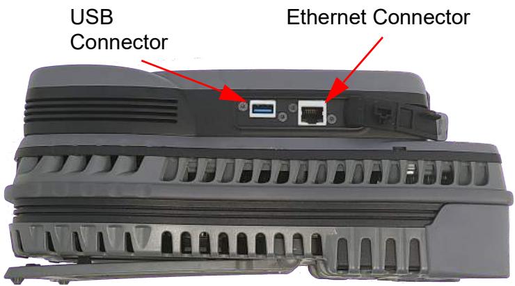
Figure 1-4 Platform Controls and Connectors

NOTE
The USB and Ethernet connectors are protected from environmental factors, such as dust, by rubber access covers; these covers should be closed securely when the connectors are not in use.
1.5.8 Ethernet Connector
The Ethernet connector is used to connect the CX100 to a network for the purpose of performing tasks such as file transfer, software updates, and remotely controlling to the device. See Figure 1-4.
See section 4.4.1.1, "Enable Network Connectivity", on page 4-10 for instructions to connect the device to a network.
1.5.9 DC Input Connector
The DC Input connector is a +12 VDC connector located on the bottom end of the device. This connector is used to connect the CX100 to the AC adapter in order to power the device and to charge the device's internal battery.
The Charge Indicator LED is located next to the DC Input connector. See section 1.6.5, "Charge Status LED", on page 1-13 for a description of this indicator.
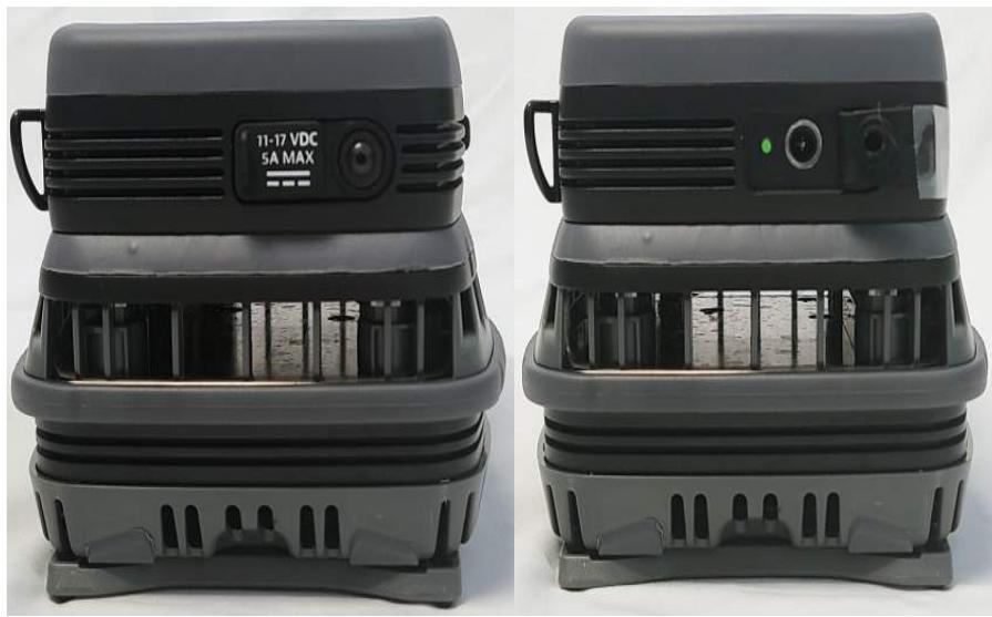
Figure 1-5 DC Input Connector Location

NOTE
The DC Input connector is protected from environmental factors such as dust by rubber access flaps; keep the access flap closed securely when the connector is not in use.
1.6 LED Indicators
CX100 front panel LED's indicate system activity and status.
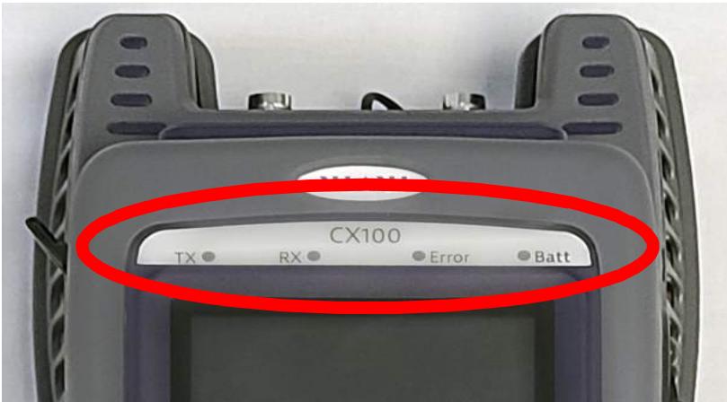
Figure 1-6 CX100 Front Panel LEDs

NOTE
The Sync and Network LEDs alternately blink green when in sleep mode (power saving mode).
1.6.1 Sync LED
The Sync LED indicates modem synchronization status.
- Blinking green indicates that the modems are training.
- Solid green indicates that the modems are synchronized and ready for use (reached Showtime).

NOTE
The Sync and Network LEDs alternately blink green when in sleep mode (power saving mode).
1.6.2 Network LED
The Network LED indicates network connectivity status.
- Blinking green indicates that the unit is trying to acquire an IP address.
Solid green indicates when an IP address has been acquired. - Blinking amber indicates a timeout; the unit was unable to acquire an IP address.
- If the Network LED is not illuminated, the network is inactive; either the unit is not connected to the network or it is logged off.
1.6.3 Error LED
The Error LED indicates error and alarm conditions. Solid red indicates error and alarm conditions. The type of errors varies depending on the application. Errors are displayed in the Utility Tray. See section 3.1.22, "Notifications", on page 3-13 for information.
1.6.4 Battery LED
The Battery LED is a multi-colored LED that indicates battery status.
- Solid green indicates the battery charge is higher than 30% or that an external source is powering the unit.
- Solid amber indicates the battery charge is getting low; the charge is between 10% and 30% .
- Solid red indicates the battery charge is critically low, less than 10% . An audible beep occurs 30 seconds before shutdown.
1.6.5 Charge Status LED
The Charge Status LED is located on the bottom of the device next to the DC Input connector. The Charge Status LED is a multi-colored LED that indicates the charge status of the device.
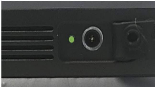
Figure 1-7 CX100 Battery LED
Solid green indicates charging is complete and the battery is fully charged.
Solid amber indicates the battery is charging.
- Slow flashing red indicates the battery charge is critically low, less than 10% .
- Fast flashing red indicates charging was suspended due to a fault and user intervention is necessary (for example, the wrong charger is attached).
- Solid red indicates charging was suspended due to overheating; no user intervention is necessary. The unit can continue to run; charging resumes when the device temperature drops to within acceptable parameters.
This page intentionally left blank.
Getting Started: Setup and Operation
This chapter contains information to get users started with using the CX100 ComXpert. This chapter reviews the following information and procedures:
Upon Receipt 2-2
Unpack the Equipment 2-2
- Inspect the Equipment 2-2
Verify Contents 2-3
Prepare for First Time Use 2-4
- Verify Operation 2-5
- Powering the Device 2-6
AC Power Operation 2-6
- Battery Operation 2-7
Power On/Off Procedures 2-7
- Turning the Device ON 2-7
- Turning the Device OFF 2-8
Device Control and Operation. 2-8
- Local Operation 2-8
Remote Operation 2-8
UI Navigation, Control and Layout 2-8
- Screen Navigation and Control 2-9
- Softkeys 2-10
- Selecting Functions and Applications 2-11
- Screen Layout. 2-12
- System Status UI Indicators 2-14
2.1 Upon Receipt
The following tasks should be performed when a CX100 is received from the factory:
Unpack the Equipment
Inspect the Equipment
Verify Contents
Prepare for First Time Use
Verify Operation
2.1.1 Unpack the Equipment

NOTE
When unpacking the device, use care not to damage the shipping container and packaging materials: materials should be stored for possible future use.
The CX100 battery is a lithium battery that is shipped in special protective packaging. When removing the packaging, use care not to damage the packaging; the protective packaging can be used in the event the battery needs to be shipped.
To Unpack the Device
- Cut and remove sealing tape from the top of the shipping container.
- Remove foam inserts and equipment from the shipping container.
- Remove the CX100 and battery from packing materials.
- Store packing material and shipping container for possible future use.
2.1.2 Inspect the Equipment
Inspect the equipment for any damage which may have occurred during shipment. Report any damage to VIAVI (see "Contact Information" on page 1-iii).
2.1.3 Verify Contents
Verify shipment is complete in accordance with packing list. Report any discrepancies to VIAVI.
2.1.3.1 Standard Items
The following items are included with the CX100 ComXpert:
Table 2-1 Standard Items
| Item | Description | Qty |
| CX100 ComXpert | 1 | |
| 22071316-002 | Battery, Lithium Ion, 7.3V, 13Ah, OneExpert | 1 |
| 22054882 | Power Supply:AC2DC;90-264VAC; 47-63HZ,12VDC | 1 |
| 22022754 | Adapter Cord US/NAmerica | 1 |
| 22144013 | CX100 ComXpert Quick Start Guide | 1 |
| 22144014 | CX100 ComXpert Operation CD | 1 |
| 22142165 | Mech; HAND STRAP | 1 |
2.1.3.2 Accessory Kits
The following are optional accessory items that are available for the CX100 ComXpert.

NOTE
Optional accessories may be included as standard items with some system configurations. Refer to the packing list for shipment contents.
Custom accessories (customer specific) are not listed in the following tables.
Table 2-2 CX100Accessory Kit #TBD
| Item | Description | Qty |
| 22147149 | CHARGER - Vehicular Adapter NATO Plug | 1 |
| 9138 | Antenna, 2-30 MHz | 1 |
| 9147 | Antenna, 225-512 MHz | 1 |
| 9151 | Antenna, 30-90 MHz | 1 |
| 22147433 | Antenna, 1-6 GHz | 1 |
| 22147031 | CONN, ADPTR TNC-M to BNC-F | 1 |
| 38240 | Attenuator, 20DB, 50W, DC-6 GHZ | 1 |
| 22147033 | Attenuator, 20DB, 200W, DC-6 GHZ | 1 |
| 22147032 | Connector, Adapter, N-F to N-M | 1 |
| 23770 | Connector, Adapter, N-F to BNC-F | 2 |
| 20327 | Connector, Adapter, N-M to BNC-F | 2 |
| 23769 | Connector, Adapter, N-F to BNC-M | 2 |
| 23773 | Connector, Barrel, N-F to N-F | 1 |
| 23758 | Connector, Adapter, TNC-M to BNC-F | 3 |
| 22149578 | Cable, RF, BNC-M to BNC-M, 48 inches | 5 |
| 22149490 | HANDSET, H-250 | 1 |
| HST-000-346-00 | SOFT CARRYING CASE | 1 |
| 22145305 | HARD CARRYING CASE | 1 |
| 22144016 | Guide, PDF, CX100 Test and Measurements | 1 |
| 22144013 | Guide, QuickStart, PP, CX100 | 1 |
| 22144014 | Manual, Operation, CD, CX100 | 1 |
| 22144015 | Manual, Operation, PDF, CX100 | 1 |
| 22149489 | CABLE, USB-C to RS-232 | 1 |
| 22149491 | CAL KIT, DC- 6 GHz | 1 |
| 22149488 | CABLE, RF, TNC-M to TNC-M, 48 inches | 2 |
2.1.4 Prepare for First Time Use
Perform the following to prepare the CX100 for verifying operation:
- Install the battery that shipped with the CX100 in the device. See section B.8, "Installing the Battery", on page B-7 for instructions.
- Remove the protective film from the LCD by pulling up on the tab located at the lower right corner of the film.
2.1.5 Verify Operation

NOTE
The following procedure is used to verify that the CX100 is operating properly; the procedure is not intended to verify that the CX100 is operating to specified performance parameters.
When the CX100 is received from the factory, perform the following before using the device for the first time:
- Power on the CX100. See section 2.2, "Powering the Device", on page 2-6 for instructions.
- Verify the LEDs located above the display flash on and off in a series of red and green during the boot-up process.
- When the device is ready for use, verify the Battery LED is illuminated.

NOTE
If the Battery LED is red, the battery needs charged (see "To Charge the Battery" on page 2-7).
- When the display loads, open the RF Instrument menu to access the RF Instrument functions.
- Select the AutoTest button.
- Select the File Field located at the top of the screen.
- Select Self Test from the test list.
- Press the Select All Soft-key.
- Press the Run Selected Soft-key.
- Wait while the device performs a series of automated test process. Do not interrupt this process or the self test will fail. Status indicators show when self test is finished.
- When AutoTest is finished, verify all portions of the test have passed. If any portion of the AutoTest procedure fails, contact VIAVI (see "Contact Information" on page 1-iii). The CX100 is now ready for use.
2.2 Powering the Device
The CX100 is designed to be powered by an internal battery or by an external AC power supply.

CAUTION
- Use only the AC Adapter/Charger supplied with the product. Contact VIAVI for approved replacement parts.
- Do not use the AC Adapter/Charger outdoors or in a wet or damp location.
- Only connect the AC Adapter/Charger to the correct mains voltage indicated on the ratings label.
Mise en Garde
Improper grounding of equipment can result in electrical shock. To ensure proper grounding, this device should only be connected to a grounded AC Power Supply.
Avertissement
2.2.1 AC Power Operation
The CX100 can be powered externally using the provided AC Power Adapter to connect the device to a grounded AC power supply. The device automatically initiates recharging the battery when the CX100 is connected to an AC power supply.
To Connect the Device to an AC Power Supply
- Connect the power cord to the AC Adapter/Charger.
- Connect the DC connector to the device's DC Input Connector. See section 1.5.9, "DC Input Connector", on page 1-10 for information.
- Connect the power cord to a grounded AC power supply.

The AC Current Icon is displayed at the top of the UI when the device is connected to an AC power supply.
2.2.2 Battery Operation
The CX100 is designed to be powered by an internal battery that supports up to 3 hours of continuous operation. The amount of battery operation time remaining is indicated by the Battery LED on the front panel. See section 1.6.4, "Battery LED", on page 1-13 for information.
The CX100 is designed with a time-out feature which conserves battery power; this feature is referred to as "Battery Saving Mode". The time-out period is defined on the Screen and Power Settings panel. See section 4.2.5.1, "Battery Saving Mode", on page 4-7 for information.
To Charge the Battery
- Connect the device to an AC power supply.
- Verify the device's Battery LED turns amber to indicate the battery is charging.
- The Battery LED turns green when the battery is fully charged.
2.3 Power On/Off Procedures
The CX100 is powered on and off using the Power button located on the front panel.

NOTE
The CX100 can be configured to emit a beep at power up/power down. See section 4.2.5.2, "Beep at Power Up/Down", on page 4-7 for information.
2.3.1 Turning the Device ON
- Press and release the Power button.
- An initializing indicator is displayed during the boot-up process. Wait while the device completes the boot-up process; this takes several seconds.
- The Home screen is displayed when the device is ready for use.
2.3.2 Turning the Device OFF
- Press and hold the Front Panel Power button for approximately 3 seconds, then release.
- The device performs a series of power-down processes.
- When the power down process is finished, the front panel LEDs will no longer be illuminated.
2.4 Device Control and Operation
The CX100 can be operated locally using the device's LCD touchscreen and front panel controls, or remotely using a VNC (Virtual Network Computing) viewing application.
2.4.1 Local Operation
The OneExpert User Interface (UI) is designed to be intuitive and easy to use. The Liquid Crystal Display (LCD) is a capacitive touchscreen that operates similarly to a mobile device. The touchscreen supports gestures such as press to open/select/activate, press and hold, press and drag, swipe sideways and pinch to zoom.
2.4.2 Remote Operation
The CX100 can be controlled from a remote location such as a laptop using a VNC viewing application. See the following sections for additional information:
- See section 4.5, "Remotely Operating the Device", on page 4-16 for instructions to configure the device for remote operation.
See section 3.1.3, "Remote Operation Panel", on page 3-5 for detailed information about remote operation controls and parameters.
2.5 UI Navigation, Control and Layout
This section describes layout of the CX100 User Interface (UI) and how to navigate between system and test applications and functions. The CX100 UI is designed to be intuitive and easy to use. The Liquid Crystal Display (LCD) is a capacitive touchscreen that operates similarly to a mobile device. The touchscreen supports gestures such as press to open/select/activate, press and hold, press and drag, swipe sideways, and pinch to zoom.
2.5.1 Screen Navigation and Control
2.5.1.1 Screen Navigation
Screens are navigated using the following controls and techniques:
- Expandable panels are opened and closed by selecting the directional arrow on the right side of the title bar.
- Arrow buttons are used to move up/down, left/right (see page 1-6).
- Swipe left/right is used to "flip through" screens on multi-tabbed screens (i.e., VSWR/DTF screen).
- The Back Arrow is used to return to the previously viewed content or to close a running function or application (see page 1-6).
2.5.1.2 Expanding Function/Application Menus
- Menu are expanded and collapsed using one of the following methods:
To Expand a Menu
- Select the triangle on the right side of the menu using the touchscreen. - OR -
- Use the Arrow buttons to highlight the desired function menu, then press the OK button.
The triangle on the right side of the menu points down when a menu is expanded.

NOTE
Function and application menu title bars are purple when selected; gray when not selected.
2.5.1.3 Select Menu Item
To Select a Menu Item
- Open the menu and select the menu item. When a menu item is selected using the touchscreen, the selection is activated upon selection and the menu closes.
- Use the Arrow buttons to highlight the desired item; press the OK button to confirm. When confirmed, the election is activated and the menu closes.
2.5.1.4 Entering Text and Numeric Data
Some parameters are defined using text or numeric entry fields (for example, test settings or user information). The process is similar to data entry on a mobile device.
To Enter Text or Numeric Data
- Select (or navigate to) the desired parameter to open the data entry field. A data entry box is displayed.
- Select (or navigate to) the data entry box. A keypad is displayed on the screen.
- Use the keypad to enter the data.
- Select the Enter/Return button on the keypad, or press the OK button. The data is entered and stored.
2.5.2 Softkeys
Some CX100 screens contain a soft-key panel at the bottom of the display. The soft-keys are used to access test settings or perform actions. The UI contains the following types of soft-keys.
Table 2-3 Types of Softkeys
| Examples | Type of Soft-key | Description |
| Clear/Reset | Action Soft-key | Identified by a label that implies/defines an action. When pressed, the system performs the action associated with the soft-key. |
| Output ON | State Soft-key | Identified by a label that identifies a parameter and a label that identifies the current state of the parameter. Some State softkeys also contain a visual indicator to the on/off state of the parameter. |
| Distortion/SINAD/SNR | Selection Soft-key | Identified by a label that identifies the parameter selections. Pressing the button selects between available selections. |
| Display Settings | Menu Soft-key | Menu soft-keys are identified by the up arrows on the soft-key. When pressed, the soft-key updates to display a menu that contains controls and setting. |
2.5.3 Selecting Functions and Applications
To Open a Function/Application
- Select the button from the function or application button from the menu.
To Close a Function/Application
- Select the Close button to close the function or application.
Function and test application buttons change color to indicate whether or not the function is current initialized (actively running) on the device.

Function Off Indicator
Indicates the function/application is inactive (turned off).

Function Running - Not Highlighted
Indicates the function/application is running in the background; focus is not on the application.
- Selecting the button reopens the function or application.
- Pressing the Close button X closes the function or application.
Function Running - Highlighted
Indicates the function/application is running in the background and you currently have focus on the application.
- Selecting the button reopens the function or application.
- Selecting the Back button × closes the function or application.
2.5.4 Screen Layout
CX100 screen layout and content changes based on factors such as the selected function, user settings and modes of operation. All screens consist of three main areas: a header, a main display area, and a footer section.
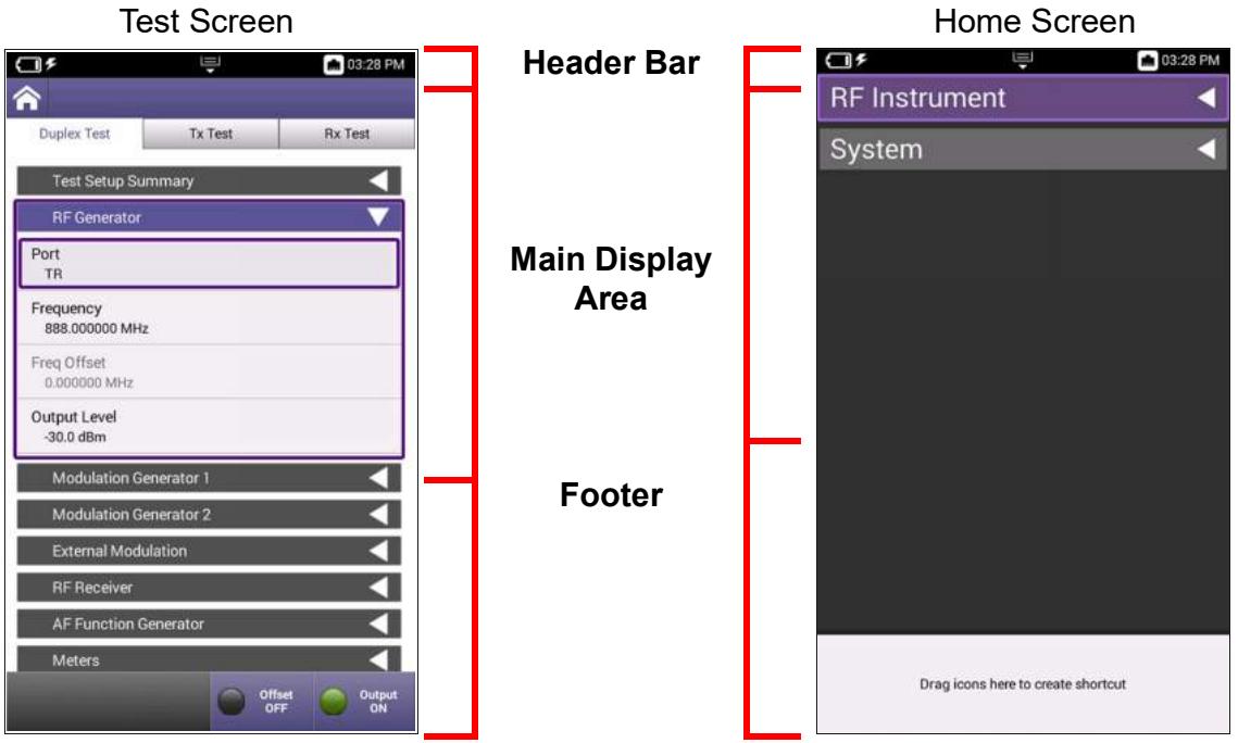
Figure 2-1 Test Screen Layout Examples
Figure 2-2 Home Screen Example
Header Bar
The header bar displays system status indicators such as battery charge status, WiFi status, and the system clock. The header bar also contains the Utility Tray button which is used to access system device tools and functions.
Main Display Area
The main display area contains a variety of components; the content that is displayed is based on the current function and action being performed. The area may contain content such as a list of expandable panels, menus, plot fields, or data tables.
Footer Area
When the footer area is present on the screen, the footer area contains either a shortcut area or a soft-key panel.
- The shortcut area is used to provide quick access to frequently used functions. See section 4.11, "Creating UI Shortcut", on page 4-21 for information.
- Soft-key panels contain controls and functions associated with the currently selected test function.
2.5.4.1 Home Screen
When the CX100 is powered on the Home screen is displayed (see Figure 2-2 on page 2-12). The Home screen contains collapsible menus that expand to provide access to the system and test functions that are available on the device.
When the device is received from the factory, the Home screen lists the standard and optional functions that are available on the device. The content displayed on the Home Screen can be changed from the Home Screen Settings panel. See section 4.2.4.1, "Customizing Home Screen Contents", on page 4-6 for information.
The Home screen footer area can be used to create short cuts to commonly used functions and applications. See section 4.11, "Creating UI Shortcut", on page 4-21 for information.
2.5.4.2 Test and System Settings Screens
CX100 test screens contain controls, settings and other UI components applicable to the selected test function. The contents of the test screens depend on the selected mode of operation as well as the active test and measurement function. See Figure 2-1 on page 2-12 for an example.
See Chapter 5 "RF Instrument Function Descriptions" for information about test screens.
See Chapter 3 "System and Utility Function Descriptions" for information about system and utility screens.
2.5.5 System Status UI Indicators
The following icons are used to indicate status of system functions.
Table 2-4 System Status UI Indicators
Battery Status Icon

The Battery Status Icon displays the charge level of the device's internal battery. The charge level is also displayed as a percent next to the indicator.
See section 2.2.1, "AC Power Operation", on page 2-6 for information about the device's internal battery.
See section 8.1, "Recharging the Battery", on page 8-2 for battery recharging instructions and relevant safety information.
AC Power Icon

The AC Power Icon is displayed when the device is connected to an AC power supply.
See See section 2.2.1, "AC Power Operation", on page 2-6 for safety information and instructions for connecting the device to an AC power supply.
Network Connection Icon

The Network Connection Icon is displayed when the device is connected to an active LAN via one of the device's Ethernet connectors.
See section 4.4.1.2, "Establishing an Ethernet Connection", on page 4-10 for instructions for connecting the device to a network via an Ethernet connection.
WiFi Icon

The WiFi Icon is displayed when the device is connected to a network via WiFi.
See section 4.4.2.2, "Connecting to a WiFi Network", on page 4-14 for instructions for connecting the device to a network via a WiFi connection.
System and Utility Function Descriptions
This chapter provides an overview of the device's system and utility functions. System settings control functions such as date and time, screen and power settings, and software updates. Utility functions are used to configure functions such as network connections and file transfers.
This chapter reviews the following topics:
Introduction 3-3
- Accessing System Settings. 3-3
- Date and Time Panel 3-4
Remote Operation Panel. 3-5
- Wireless Personal Area Network (WPAN) Settings Panel 3-6
International Settings Panel 3-6
Network Software Update panel 3-7
- USB Software Update Panel 3-8
- Hardware & Software Revisions Panel 3-9
- Software Options Panel 3-9
- Hardware Options Panel 3-9
- Calibration Screen. 3-10
Home Screen Settings 3-10
- Save Location Settings 3-10
- Restore Factory Defaults Settings. 3-11
Power Off Screen 3-11
- Template Management Screen 3-11
- Screen & Power Management 3-12
- Sounds Screen 3-12
- Theme. 3-12
- User Information 3-13
Help. 3-13
- Notifications. 3-13
- System Network Screen 3-13
Web Browser 3-17
File Browser. 3-17 - USB File Browser 3-18
Utility Functions 3-19
- Accessing Utility Functions 3-19
Save Report Button 3-19
View Report 3-20 - Screen Shot. 3-20
Network Button 3-20 - Wireless Personal Area Network (WPAN)® Button. 3-20
Volume Button 3-20 - Help 3-20
- Tutorial. 3-21
- Workflow Manager. 3-21
- Templates 3-21
See Chapter 4 "Configuring System Settings" for step by step instructions for configuring CX100 system settings, network connections and user settings.
3.1 Introduction
CX100 system settings configure device parameters such as date and time, screen layout and brightness and battery saving mode, network, WiFi and Wireless Personal Area Network (WPAN) access. Utility functions support file management, user setup information and updating the device's software and firmware.
3.1.1 Accessing System Settings
System settings are accessed from the System Menu on the Home screen and from the System Settings menu.
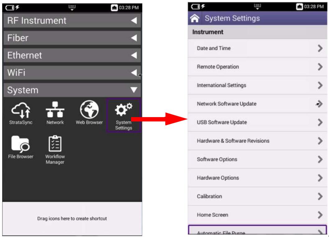
Figure 3-1 System Settings Menu Access
To Access System Settings Menu
- Navigate to the Home screen.
- Open the System menu.
- Select the System Settings button to open the System Settings menu.
3.1.2 Date and Time Panel
The date and time controls and settings are used to configured the device's internal clock and calendar. The date and time can be configured manually, or configured to synchronize automatically to a central time server.
When Time Synchronization is set to None, the date and time fields update to editable fields. See section 4.2.3, "Setting Date and Time", on page 4-4 for instructions.
When NTP Synchronization is enabled, Network Time Protocol (NTP) synchronizes the device's system clock to a central time server. See section 4.2.3.6, "Time Synchronization", on page 4-5 for instructions.
Table 3-1 Date and Time Controls and Settings
| Control/Setting | Description |
| Time | The CX100's clock can be set manually by selecting this field. When the field is selected, a configuration window opens which is used to set the device's clock. |
| Date | The CX100 calendar can be set manually by selecting this field. When the field is selected, a configuration window opens which is used to set the date. |
| Date Format | Selecting this field opens a window to select between supported UTC date formats. |
| Time Format | Selecting this field opens a window to select between 12 hour or 24 hour time format. |
| Time Zone | Selecting this field opens a window to adjust the device's clock to reflect a different time zone. The CX100's clock updates automatically to reflect the selected adjustment. |
| DST Used | This setting selects whether or not Daylight Savings Time (DST) is used. |
| Time Synchronization | This setting selects the method used for time synchronization. See section 4.2.3.6, “Time Synchronization”, on page 4-5. |
| NTP Server Address Type | This setting selects the formatting type used for the Network Time Protocol (NTP) Server IP Address. |
| NTP Server | This field is the address of the server where the device gets the time, for example 0.us.pool.ntp.org. |
| NTP Synchronization State | This field indicates if the device is synchronized with the NTP. |
3.1.3 Remote Operation Panel
Remote operation settings are used to configure the device for remote operation. See section 4.5, "Remotely Operating the Device", on page 4-16 for step by step instructions for configuring the device for remote operation.
The VNC parameters are used to configure the device for remote access and operation. See section 4.5.1, "Establishing VNC Viewer Connection", on page 4-16 for instructions to configure the device for remote operation.
Table 3-2 Remote Operation and VNC Controls and Settings
| Control/Setting | Description |
| Enable HTTP File Server | When this check box is selected, files can be downloaded from the CX100 via a web browser. See section 7.2.5, “Downloading Files via Web Browser”, on page 7-6 for instructions. |
| Enable VNC Server | This tick box must be selected in order to access the device using a remote UI viewing application. |
| VNC Password | This field defines a password that will be required when accessing the device remotely using VNC viewing application. |
| Connected Viewers | This indicates how many users are remotely connected to the device. |
| Reserve Ethernet Port for Remote Access | This check box enables simultaneous usage of System Network access and Data Test access on the CX100’s Ethernet connectors. System Network access will use Ethernet 1 Connector; Data Testing will use Ethernet 2 Connector. If this option is not selected, either connector can be used for System Network Access. |
3.1.4 Wireless Personal Area Network (WPAN) Settings Panel
The WPAN Settings panel contains controls that are used to establish and manage a Wireless connection between the CX100 and another compatible device. The WPAN Settings panel remains blank until WPAN capability is enabled and a scan is performed.
Table 3-3 Wireless Personal Area Network Controls and Settings
| Control/Setting | Description |
| Enabled Tick Box | The tick box enables and disables the CX100's WPAN function. |
| Device List | Displays a list of devices that the CX100 detected on the network that are available for WPAN connection. |
| Scan for Devices Soft-key | This soft-key scans the network to which the CX100 is connected for WPAN enabled devices. |
See section 4.6.1, "Enabling Wireless Personal Area Network (WPAN) Connectivity", on page 4-17 for information.
3.1.5 International Settings Panel
International Settings panel contains controls and settings that allows the CX100 to be configured to use local settings such as units of measure, local time zone and temperature units. International settings can be defined by selecting a preset country or by configuring the settings manually.
See section 4.2.2, "Configuring International Settings", on page 4-3 for information.
3.1.6 Network Software Update panel
The Network Software Update panel contains the controls and parameters used to update CX100 software when files have been placed in a network location. See section 4.7, "Updating the Device's Software", on page 4-18 for step by step instructions for updating the device's software.
Table 3-4 Network Software Update Controls and Settings
| Control/Setting | Description |
| Update URL | The Update URL field defines the URL address from where the device will download the software. This URL should be accessible to the device without security restrictions. |
| Username and Password | A user name and password can be created to secure the device against undesired updates. |
| Force Software Update | When performing a software update, the device determines if a software load is more current than the software currently installed on the device. If the software load is older, or the same version as the software installed on the device, the system determines that there is not a software update available. Selecting the tick box “Force Software Update” causes the device to update software regardless of version time/date information. |
| Update Soft-key | Pressing the Update soft-key starts the software update procedure. An error message is generated if a configuration error (i.e., does not detect software file) prevents the device from updating software. |
3.1.7 USB Software Update Panel
The USB Software Update panel is used to update the device when files have been placed on a USB Device. See section 4.7.2.1, "USB Update Procedure", on page 4-18 for instructions.
Table 3-5 USB Software Update Controls and Settings
| Control/Setting | Description |
| No USB File | When a USB is connected to the device, this field updates to allow the user to select the file on the USB device. This field is disabled until the devices detects a USB device connected to one of the USB connectors. |
| Force Software Update | When performing a software update, the device determines if a software load is more current than the software currently installed on the device. If the software load is older, or the same version as the software installed on the device, the system determines that there is not a software update available. Selecting the tick box “Force Software Update” causes the device to update software regardless of version time/date information. |
| Update Soft-key | The Update soft-key is enabled when a USB device is detected. Pressing the Update soft-key starts the software update procedure. An error message is generated if a configuration error (i.e., does not detect software file) prevents the device from updating software. |
3.1.8 Hardware & Software Revisions Panel
The Hardware & Software Revisions panel lists identifying information for major hardware components as well as software version for the device. The following data is key product information that may be required when updating or contacting VIAVI for technical support:
Table 3-6 Hardware & Software Revision Data
| Content | Description |
| Base | Version of software installed in OneExpert platform. |
| RTS | Version of software installed in CX100 RF Application Module. |
| Unit ID | Serial number of the OneExpert platform. |
| Assembly ID | Serial number of the CX100 RF Application Module. |
| Battery Information | Battery type, serial number, and manufacture date. |
3.1.9 Software Options Panel
The Software Options panel lists any available software options that are supported on the device with the current base unit and application module configuration. This panel is also used to install or update options on the device. See section 4.8.3, "Installing Options", on page 4-20 for information.
Table 3-7 Software Options Controls and Settings
| Field/Control | Description |
| Options List | Identifies software options that can be installed on the device. |
| Activation | Activation status field indicates whether or not the option is enabled or “Upgradeable” (needs to be purchased). |
| Import from USB Soft-key | This soft-key is enabled when a USB device is connected to the device containing software options which can be installed on the device. |
3.1.10 Hardware Options Panel
The Hardware Options panel lists any hardware options that are available for the current base unit and application module configuration.
3.1.11 Calibration Screen
The Calibration panel lists the device's calibration files. Content includes the name of the component for which the calibration file applies and the calibration date and time stamp.
3.1.12 Home Screen Settings
The tick boxes on the Home Screen Settings panel select the functions that are displayed on the CX100 Home Screen. Changes are immediate; the device does not need to be rebooted. See section 4.2.4.1, "Customizing Home Screen Contents", on page 4-6 for information.
3.1.13 Save Location Settings
The instrument can be configured to automatically save test results, screen captures or other files to a user defined location. The controls and settings on the Save Location panel are used to define the location where the device's file manager saves the files.
The CX100 can be configured to save test results, screen captures, or other files to the device's file system, a connected USB drive, or both (if applicable).
See section 4.2.7, "Specifying File Save Location", on page 4-8 for information.
Table 3-8 Save Location Settings
| Setting | Description |
| File System | When File System is selected, files are saved to the device's internal storage directory. Files are accessed from the File Browser screen. |
| USB Device | When USB device is selected, files are saved to a USB device that is connected to the device. This selection is only available when a USB device is detected. |
| Both | When Both is selected, files are saved to a USB device and to the device's internal storage directory. This selection is only available when a USB device is detected. |
3.1.14 Restore Factory Defaults Settings
Restoring factory defaults resets test application settings and system settings (such as brightness, contrast, and volume) to their factory default settings. See section 4.2.1, "Restore Factory Defaults", on page 4-2 for information.
Table 3-9 Restore Defaults Settings
| Setting | Description |
| Remove All Files Under File Browser | When this tick box is selected, any user files located in the File Browser directories will be deleted as part of the restore factory default process. |
| Clear International Settings | When this tick box is selected, international settings will be cleared and reset as part of the restore factory default process. |
3.1.15 Power Off Screen
The Power Off panel allows users to power off or reboot the device from a remote location.

NOTE
If the device is using DHCP network connection, the network may assign a new IP Address when the device is rebooted.
3.1.16 Template Management Screen
The Template Management function is used in conjunction with StrataSync, which is not yet supported on the CX100.
3.1.17 Screen & Power Management
The Screen & Power Management Screen contains settings that adjust the brightness of the LED backlight, the backlight timeout and the battery saver timeout. See section 4.2.5, "Configure Device Power Settings", on page 4-7 for procedures.

NOTES
"Idle time" refers to time during which no keys are pressed and no line activity takes place. If the Power Off Delay is set to 5 minutes and a 15 minute test is started, the unit will not power down during the test because there is activity on the line (as a result of the test).
Battery Saving Mode is not applicable when the device is connected to an AC power supply.
Table 3-10 Screen and Power Management Settings
| Setting | Description |
| Backlight | This setting adjusts the brightness setting of the LED's backlight. |
| BacklightTimeout | This setting defines the amount of time the device can remain idle before the LED's backlight turns off. |
| Power Off Delay | The Power Off Delay setting defines how long the instrument remains idle before the instrument automatically powers itself off when operating on battery power. |
3.1.18 Sounds Screen
The Sounds panel contains settings that configure the device to emit a chime when the Power button is pressed to turn the device on or off. See section 4.2.5.2, "Beep at Power Up/Down", on page 4-7 for information.
3.1.19 Theme
The UI Theme panel contains settings that allow users to change the color scheme of the UI. Changes take effect immediately; the device does not need to be rebooted to apply selection.
3.1.20 User Information
The User Information panel contains settings used to identify the technician using the device. Information includes the technician's name and ID as well as the StrataSync account ID. The information entered on this panel is used when synchronizing with the StrataSync server. See section 4.2.6, "User Information", on page 4-7 for information

NOTE
StrataSync is not currently supported on the CX100. Support is planned for future development.
3.1.21 Help
The Help panel contains VIAVI contact information: phone number; email and website. Help content can also accessed by pressing the Help button located in the Utility Tray.
3.1.22 Notifications
Error messages and user notifications are displayed in the Utility Tray. When more than one notification message is displayed, an individual message can be deleted by dragging the message off the screen. Pressing the Clear All button deletes all notification messages.
3.1.23 System Network Screen
Network connections are used to update the firmware, transfer files, synchronize to the StrataSync server, or control the instrument's user interface remotely. The device supports wired network and intranet, and WiFi connections.
The device supports IPv4, IPv6 and IPv4/IPv6 Dual Stack network modes of operation. The network controls and settings that are displayed on the screen depend on the Network Mode and Address Mode that are selected (Static or DHCP).
The device is designed to auto-detect when it is connected to an active network via one of the CX100 Ethernet connectors.
3.1.23.1 Accessing System Network Screen
The Network panel contains parameters that are used to configure the device for network access. The Network panel is accessed by selecting the Network button from the System Menu.
3.1.23.2 Network Controls and Settings
This section describes the controls and settings used to configure the device's network connection. See section 4.4, "Establishing a Network Connection", on page 4-10 for step by step instructions for configuring the device for network access.
Table 3-11 Network Controls and Settings
| Control/Setting | Description |
| Network Mode | Selects the method used to assign IP Addresses to the device. ·IPv4: uses 32-Bit, numeric IP addressing method ·IPv6: uses 128-Bit, alphanumeric IP addressing method. ·IPv4 and IPv6: uses both addressing methods |
| IP Address Mode | Selects whether the device connects to the network using a DHCP or Static IP Address. Dynamic Host Configuration Protocol (DHCP) The server of the network to which the device is connecting assigns network uplink IP address, netmask, gateway, and DNS. Static Static mode is used to manually define network IP connections. |
| NOTE Improperly configuring a static IP address could cause conflicts on your network server. VIAVI recommends contacting your network administrator before configuring the device to use a static IP address. | |
| IP Address | Address assigned to the device. Format is determined by select Network mode. |
| Netmask | Netmask Address assigned to the device determines whether the packets are to be routed to other networks or subnetworks. |
| Gateway | The address for the gateway that is used to route packets that are not on the same subnet. |
| DNS Server | The address of the Domain Name System (DNS) Server. |
| Network On/Off Soft-key | Enables or disables network connection using defined settings. Network connectivity can also be enabled or disables using the Network button located in the Utility Tray. |
3.1.23.3 IPv4/IPv6 Dual Stack Network Mode Settings
Table 3-12 IPv4/IPv6 Dual Stack Network Controls and Settings
| IPv4 Address Mode | Setting |
| DHCP | No additional settings. |
| Static | See section 3.1.23.4, “IPv4 Network Mode Settings”, on page 3-15. |
| Stateless | See section 3.1.23.5, “IPv6 Network Mode Settings”, on page 3-16. |
3.1.23.4 IPv4 Network Mode Settings
Table 3-13 IPv4 Network Controls and Settings
| IPv4 Address Mode | Setting |
| Static | IPv4 AddressEnter the device's IP address (which will be used when accessing the provider network).IPv4 NetmaskEnter the netmask address to indicate whether the packets are to be routed to other networks or subnetworks. |
| IPv4 GatewayEnter the address for the gateway that is used to route packets that are not on the same subnet. | |
| IPv4 DNS ServerEnter the address of the DNS server. | |
| Shared | Share the IP from another interface (for multi interface mode). |
3.1.23.5 IPv6 Network Mode Settings
Table 3-14 IPv6 Network Controls and Settings
| IPv6 Address Mode | Setting |
| DHCPv6 | No additional settings. |
| Stateless | IPv6 DNS Address ModeDHCPv6: no additional settings to specify.Manual: specify the IPv6 DNS Server address.IPv6 DNS ServerEnter the address of the DNS server. |
| Static | IPv6 Global AddressEnter the device's IPv6 address to access the global network.IPv6 Local AddressManual: Enter the IPv6 Local Address.Automatic: Address is populated automatically.IPv6 Subnet Prefix LengthEnter the subnet prefix length.IPv6 GatewayEnter the address for the gateway that is used to route packets that are not on the same subnet.IPv6 DNS Address ModeDHCPv6: no additional settings to specify.Manual: Enter the IPv6 DNS Server address.IPv6 DNS ServerEnter the address of the DNS server. |
3.1.24 Web Browser
The CX100 web browser works in the same manner as a computer or smart device. When the CX100 is connected to a network, the web browser can be used to perform maintenance procedures such as update software, enable options or access additional product documentation on the VIAVI website.
The Edit and DeleteBookmark soft keys are used to modify or delete any defined bookmarks.
See section 4.12, "Customizing the Web Browser", on page 4-22 for information about configuring the Web Browser.
3.1.25 File Browser
The File Browser is used to navigate and manage contents of the device's internal directories or contents of a USB device (when one is attached to the device). The File Browser panel is used to copy files to and from the device. See section 7.2, "Managing Files", on page 7-4 for detailed instructions.
3.1.25.1 File Options Soft-key
The File Options soft-key accesses controls for copying, editing and transferring files to and from the device.

NOTE
Functions such as copy, cut, paste and delete are not available for system files.
3.1.25.2 Copy, Cut and Paste File Options
Copy, Cut and Paste options allow user created files to be moved from one file location to another within the device's file storage system.
3.1.25.3 Upload FTP/HTTP
The CX100 supports Hyper Text Transfer Protocol (HTTP) and File Transfer Protocol (FTP) for transferring files to and from the device. See section 7.2.6, "Uploading Files Using FTP/HTTP", on page 7-6 for instructions.
3.1.25.4 Copy to USB
Copy to USB is enabled when the CX100 detects a USB device connection. Selecting this button copies selected file(s) to the attached USB device.
When 2 USB devices are connected to the device, the CX100 defaults to the USB device connected to USB 1 Connector.
3.1.25.5 Send to Android Device (WPAN)
When the device is connected to an Android device via WPAN®, files can be transferred directly from the CX100 to the Android device.
3.1.25.6 Show Hidden Files
The CX100 allows users to configure files as "hidden" in order to protect important files from being accidentally deleted. Selecting the Show Hidden Files check box displays all hidden files on the device.
3.1.25.7 Rename Soft-key
Pressing the Rename soft-key opens a pop-up window that allows users to rename a saved file.testfile.png. The new file name takes effect immediately when entered; no confirmation requested.
3.1.25.8 Delete Soft-key
Pressing the Delete soft-key deletes the selected file or directory. A prompt will be displayed prior to deleting files to help prevent users from unintentionally deleting files.
3.1.25.9 Open Soft-key
Pressing the Open soft-key opens the selected file or directory.
3.1.26 USB File Browser
The USB File Browser button is populated when a USB device is connected to the test set. Pressing the button opens a window which access the contents of the USB device.
Chapter 7 "Managing Files and Reports" for related information.
3.2 Utility Functions
Utility functions allow the user to perform tasks on the device more conveniently. For example, users can view saved test reports on the device using the View Reports function, or the user can enable a network connection from the Utility Tray instead of navigating through menus to the Network Screen.
3.2.1 Accessing Utility Functions
To Open the Utility Tray
- Press the Tray button located on the device's front panel.
-OR- - Swipe/pull downward on the Tray soft-key located at the top of the UI.
See section 1.4.7, "Utility Tray Button", on page 1-6 for button locations.
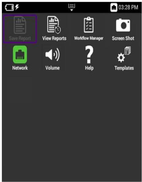
Figure 3-2 CX100 Utility Tray - Example
3.2.2 Save Report Button
The Save Report button allows you to create reports based on the configuration settings and test results for the currently active test. See section 7.1.3, "Saving a Report", on page 7-3 for details.
3.2.3 View Report
Saved reports can be viewed on the device using the View Report button. See section 7.1.4, "Viewing a Report", on page 7-4 for details.

NOTE
The View Report button is disabled when there are no reports saved on the device.
3.2.4 Screen Shot
The CX100 provides users with the ability to capture screen shots of content actively displayed on the UI. This function would be useful for capturing shots of signal traces or constellation plots. See section 4.9, "Capturing a Screen Shot", on page 4-21 for details.
3.2.5 Network Button
The Network button is used to enable or disable network connectivity. The Network button turns green when network connectivity is enabled. Network connections are configured on the Network Screen. See section 4.4.1, "Establishing an Ethernet Connection", on page 4-10 for detailed instructions.
3.2.6 Wireless Personal Area Network (WPAN)® Button
The WPAN® button is used to enable or disable WPAN capability. The button turns green when Wireless Personal Area Network is enabled. WPAN connections are configured on the WPAN panel. See section 4.6, "Establishing a Wireless Personal Area Network (WPAN) Connection", on page 4-17 for detailed instructions.
3.2.7 Volume Button
The Volume button opens a panel that contains settings that control the device's volume. Changing this setting does not affect the volume of the power button chime setting. See section 3.1.18, "Sounds Screen", on page 3-12 for information about the power chime.
3.2.8 Help
The Help button opens a panel that contains VIAVI contact information: phone number; email and website. Help content can also accessed by pressing the Help button located in the System Settings menu.
3.2.9 Tutorial
The Tutorial function is used in conjunction with StrataSync which is not yet supported on the CX100.
3.2.10 Workflow Manager
Workflow Management function is used in conjunction with StrataSync which is not yet supported on the CX100.
3.2.11 Templates
The Template function is used in conjunction with StrataSync which is not yet supported on the CX100.1
This page intentionally left blank.
Configuring System Settings
This chapter provides step by step instructions for performing the following:
- Locating Device's Unit ID. 4-2
- Configuring Device Settings. 4-2
- Configuring 10 MHz Frequency Reference 4-9
- Establishing a Network Connection 4-10
- Remotely Operating the Device 4-16
- Establishing a Wireless Personal Area Network (WPAN) Connection 4-17
- Updating the Device's Software. 4-18
- Hardware/Software Versions and Options 4-20
- Capturing a Screen Shot 4-21
- Enabling Password Protection 4-21
- Creating UI Shortcut 4-21
- Customizing the Web Browser. 4-22
See Chapter 3 "System and Utility Function Descriptions" for detailed descriptions of the system settings and parameters.
4.1 Locating Device's Unit ID
The CX100's unit identifier (ID) is located on the Hardware & Software Revisions panel. See section 4.8.1, "Viewing Hardware/Software Revision Information", on page 4-20 for information. The Unit ID number matches the unit serial number on the product's label.
4.2 Configuring Device Settings
This section provides instructions for configuring the device's system settings. See Chapter 3 "System and Utility Function Descriptions" for detailed descriptions of the functions.
4.2.1 Restore Factory Defaults
The following procedure describes how to reset the CX100 to factory default settings.

NOTE
Restoring factory defaults resets test application settings and system settings (such as remote and VNC settings, brightness, contrast, and volume), and powers down the unit.
To Restore Factory Default Settings
- Navigate to the Restore Factory Settings panel (System Settings >Restore Factory Defaults).
- At prompt, select any additional action(s) to be performed.
- Press the OK button to continue.
- Press the Reboot button to acknowledge the information in the prompt and to restore the device to factory default settings.
- Reboot the device to activate the default settings.
4.2.2 Configuring International Settings
4.2.2.1 Preset International Settings
To Select Preset Country Settings
- Navigate to the International Settings panel (Systems Settings > International Settings).
- Select the Country button to open the preset country list. Select the desired preset country from the list. When a preset country is selected, the system automatically configures the remaining International Settings to selections appropriate for the selected country.
- A user prompt window is displayed notifying the user that the device must be rebooted to apply the settings. Select the OK button to continue.
- Reboot the device (turn off the power, then turn it back on).
- The international settings are configured and the user interface is localized.
4.2.2.2 Manually Configure International Settings
To Manually Configure International Settings
- Navigate to the International Settings panel (Systems Settings > International Settings).
- If desired, select a preset country that has settings closest to desired settings.
- The system will display a user prompt window indicating the device must be rebooted in order for the new settings to be applied.
- Press the OK button to continue.
- Change additional settings as desired, selecting the OK button at each prompt to continue configuring settings.
- Press the Back function key to exit the menu.
- When all settings have been configured as desired, reboot the device to apply all changes.
4.2.3 Setting Date and Time
The CX100 contains an internal clock that can be set to provide accurate time stamps for test results.

NOTE
Time Synchronization must be set to None in order to edit Time and Date settings.
4.2.3.1 To Set the Time
To Set the Device's Clock
- Navigate to the Date and Time panel (System Settings > Date and Time).
- Select the Time button.
- Adjust the dials to select the hour, minutes, and AM or PM.
- Press the OK button to apply the selected time.
4.2.3.2 Set the Date
To Set the Device's Calendar
- Navigate to the Date and Time panel (System Settings > Date and Time).
- Select the Date button.
- Use the arrows to set the month and year.
- Select the day on the calendar.
- Press the Set button to apply the selected date.
4.2.3.3 Select Date Format
To Select the Date Format
- Navigate to the Date and Time panel (System Settings > Date and Time).
- Select the Date Format button.
- Select MM/DD/YYYY or DD/MM/YYYY format. Change is applied at time of selection.
4.2.3.4 Select Time Format
To Select the Time Format
- Navigate to the Date and Time panel (System Settings > Date and Time).
- Select the Time Format button.
- Select 12 Hour or 24 Hour. Change is applied at time of selection.
4.2.3.5 Select Time Zone
To Select the Time Zone
- Navigate to the Date and Time panel (System Settings > Date and Time).
- Select the Time Zone button.
- Select the desired time zone.

NOTE
If Daylight Savings Time (DST) is used in your area, select the DST Used check box to enable DST. A check mark indicates DST is enabled.
4.2.3.6 Time Synchronization
- Navigate to the Date and Time panel (System Settings > Date and Time).
- Select the desired setting for Time Synchronization (None or NTP).
- If NTP is selected, specify the following NTP Parameters:
NTP Server Address type (IPv4 Address, IPv6 Address, DNS Name)
- NTP Server (the address of the server where the device gets the time, for example 0.us.pool.ntp.org)
- The NTP Synchronization State button indicates if the device has synchronized with the NTP server.
- The date and time are set. Press the Back button to exit the menu.
4.2.4 Change Display Content and Settings
The CX100 UI can be configured according to user preferences and requirements.
4.2.4.1 Customizing Home Screen Contents
To Change Home Screen Content
- Navigate to the Home Screen Settings panel (Systems Settings > Home Screen).
- Enable or disable the functions you want listed on the device's Home screen. Changes are immediate, does not require device reboot.
- Press the Back Arrow to return to the System Settings panel.
- Press the Home button to return to the Home screen.
- The new Home screen settings will be saved and applied for future use.
4.2.4.2 Configure Backlight Brightness
To Change Brightness of LCD Display
- Navigate to the Screen & Power Management panel (System Settings > Screen & Power Management button).
- Select the Backlight button.
- Use the +/- buttons or the vertical slider to adjust the brightness to the desired setting.
- Press the OK button to apply new setting.

NOTE
Use the back arrow to exit without applying a new value.
4.2.4.3 Configure Backlight Timeout
To Change Display Timeout
- Navigate to the Screen & Power Management panel (System Settings > Screen & Power Management button).
- Select the Backlight Timeout button.
- Select the amount of time to wait before the backlight dims. The new setting is applied when selected.
4.2.5 Configure Device Power Settings
4.2.5.1 Battery Saving Mode
To Set the Power Off Delay
- Navigate to the Screen & Power Management panel (System Settings > Screen & Power Management button).
- Select the Power Off Delay button.
- Select the amount of idle time to wait before the device automatically powers itself off. The new setting is applied when selected.
4.2.5.2 Beep at Power Up/Down
To Power Up/Down Beep
- Open the Sound Settings panel.
- Select the Play Chime on Power Up/Down tick box.
- Select the Power Up/Down Chime Volume field to adjust volume of the chime to the desired volume.
- Press the OK button to confirm.

NOTE
Change takes effect immediately; the device does not need to be rebooted to apply the change.
4.2.6 User Information
The User Information menu allows users to enter operator information such as the technician's name and ID.
To Specify User Information
- Navigate to the User Information (System Settings > User Information).
- Enter the desired user information.
- Press the Back button to exit the menu.
4.2.7 Specifying File Save Location
The CX100 can be configured to save test results, screen captures, or other files to the device's file system, a connected USB drive, or both (if applicable).
To Specify Location for Saved Files
- Navigate to the Save Location panel (System Settings > Save Location button).
-
Select the location to which files should be saved.
-
Filesystem
USB Device
Both (when applicable) -
Press the Back button to exit the menu. Files will be saved to the location (and/or device) specified.
4.2.8 Setting the Volume
The device's volume is adjusted selecting the Volume button from the Utility Tray.
To Adjust Volume Settings
- Open the Utility Tray.
- Select the Volume button.
- Use the + / - buttons or the vertical slider to adjust the volume to the desired setting.
- Press the OK button to apply new setting. Use the Back arrow to exit without applying a new value.
- Press the Back button to exit the menu. The volume is set on the device.
4.3 Configuring 10 MHz Frequency Reference
To Configure CX100 to Use External 10 MHz Frequency Reference
- Connect a valid 10 MHz frequency reference to the CX100 10 MHz Frequency Reference I/O connector.
- Power on the CX100.
- Open the RF Instrument Menu.
- Select the Freq Reference button.
- Select External from the configuration window.
- Press the OK button to confirm and close the configuration window.
To Configure CX100 as a 10 MHz Frequency Reference Source
- Connect a 10 MHz frequency reference cable to the CX100 10 MHz Frequency Reference I/O connector.
- Connect the other end to external device.
- Power on the CX100.
- Open the RF Instrument Menu.
- Select the Freq Reference button.
- Select Internal from the configuration window.
- Press OK button to confirm and close the configuration window.
4.4 Establishing a Network Connection
4.4.1 Establishing an Ethernet Connection

NOTE
When the device is configured for DHCP mode, network information is likely to change when the device is connected, then reconnected to a network. If your procedure requires a known IP, configure the device for Static IP network mode of operation.
Wireless Personal Area Network (WPAN) and WiFi interfaces cannot be ON at the same time.
4.4.1.1 Enable Network Connectivity
Network connectivity must be enabled in order to establish a connection to an Ethernet or WiFi network.
To Enable Network Connectivity
- Open the Utility Tray.
- Select the Network button.
- The button turns green when network connectivity is enabled.
4.4.1.2 Establishing an Ethernet Connection
To Establish an Ethernet Connection to the Device
- Enable network connectivity on the CX100. See section 4.4.1.1, "Enable Network Connectivity", on page 4-10 for information.
- Connect one end of the ethernet cable to one of the CX100's Ethernet connectors.
- Connect the other end of the ethernet cable to an active LAN.
- Navigate to the Network panel (System Settings > Network).
- Select the Ethernet button at the bottom of the screen.
- The UI updates to show parameters necessary to connect to a LAN.
- Select Network Mode button to display available network mode options.
-
Select desired Network mode.
-
Additional settings are required based on the selected Network Mode of operation. See one of the appropriate sections to configure the device's IP settings to match the LAN settings:
See section 4.4.2, "Establishing a WiFi Connection", on page 4-13.
See section 4.4.1.2.2, "IPv4 Network Mode Settings", on page 4-11.
See section 4.4.1.2.3, "IPv6 Network Mode Settings", on page 4-12.
4.4.1.2.1 IPv4/IPv6 Dual Stack Network Mode Settings
| IP Dual Stack Address Modes | Setting |
| DHCP | No additional settings |
| Static | See section 4.4.1.2.2, “IPv4 Network Mode Settings”, on page 4-11. |
| Stateless | See section 4.4.1.2.3, “IPv6 Network Mode Settings”, on page 4-12 |
When all settings have been configured, select the Network On/Off soft-key to enable network connectivity. The device establishes an Ethernet connection to the LAN.
4.4.1.2.2 IPv4 Network Mode Settings
| IPv4 Address Mode | Setting |
| DHCP | No additional settings. |
| Static | IPv4 Address • Enter the device's IP address (which will be used when accessing the provider network). |
| IPv4 Netmask • Enter the netmask address to indicate whether the packets are to be routed to other networks or subnetworks. | |
| IPv4 Gateway • Enter the address for the gateway that is used to route packets that are not on the same subnet. | |
| IPv4 DNS Server • Enter the address of the DNS server. | |
| Shared | Share the IP from another interface (for multi interface mode). |
When all settings have been configured, select the Network On/Off soft-key to enable network connectivity. The device establishes an Ethernet connection to the LAN.
4.4.1.2.3 IPv6 Network Mode Settings
| IPv6 Address Mode | Setting |
| DHCPv6 | No additional settings. |
| Stateless | IPv6 DNS Address ModeDHCPv6: no additional settings to specify.Manual: specify the IPv6 DNS Server address. |
| IPv6 DNS ServerEnter the address of the DNS server. | |
| Static | IPv6 Global AddressEnter the device's IPv6 address to access the global network. |
| IPv6 Local AddressManual: Enter the IPv6 Local Address.Automatic: Address is populated automatically. | |
| IPv6 Subnet Prefix LengthEnter the subnet prefix length. | |
| IPv6 GatewayEnter the address for the gateway that is used to route packets that are not on the same subnet. | |
| IPv6 DNS Address ModeDHCPv6: no additional settings to specify.Manual: Enter the IPv6 DNS Server address. | |
| IPv6 DNS ServerEnter the address of the DNS server. |
When all settings have been configured, select the Network ON/Off soft-key to enable network connectivity. The device establishes an ethernet connection to the LAN.
4.4.2 Establishing a WiFi Connection
The WiFi option allows the device to be connection to a wireless network to export reports, screen shots, or job tickets (using FTP), or update the device's firmware.

NOTE
The CX100 supports 2.4 GHz and 5 GHz WiFi.
4.4.2.1 Adding a WiFi Network Profile
The CX100 can save up to 32 WiFi network profiles. If an access point does not broadcast a Service Set Identifier (SSID), a WiFi profile can be created manually. The device will save the profile, then automatically authenticate and establish a connection to the network when the following conditions are met:
Network connectivity is enabled.
The network's access point is in range.
- The network is determined to provide the best available access point (based on signal strength and/or encryption supported).

NOTE
The CX100 automatically saves a WiFi network profile after successfully connecting to the WiFi network.
To Add a WiFi Network Profile
- Enable network connectivity on the CX100. See section 4.4.1.1, "Enable Network Connectivity", on page 4-10 for information.
- Navigate to the Network panel (System button > Network button). The System Network menu appears.
- Select the WiFi button located on the soft-key panel. The device immediately scans for WiFi networks and lists each network as an item.
- Select Add Network. The Add WiFi Network controls and settings are displayed.
- Specify the following settings:
| Setting | Value |
| SSID | TheSSID (Service Set Identifier) of the WiFi network. |
| Password | The password required to authenticate to the network. A password is not required if Key Management is set to None. |
| Key Management | Select the Wi-Fi Protected Access (WPA) key management. |
| Network Mode | Select the Network Mode. |
| Additional settings are required based on the selected Network Mode of operation. See the appropriate section to complete network configuration: | |
| See section 4.4.1.2.2, “IPv4 Network Mode Settings”, on page 4-11. | |
| See section 4.4.1.2.3, “IPv6 Network Mode Settings”, on page 4-12. | |
| See section 4.4.1.2.1, “IPv4/IPv6 Dual Stack Network Mode Settings”, on page 4-11. |
- Return to the System Network panel. The network profile just created now appears on the list.
4.4.2.2 Connecting to a WiFi Network
The CX100 can be connected to any compatible WiFi network within range of the device for which you have authorized access (and a password for authentication).
To Connect to a WiFi Network
- Enable network connectivity on the CX100. See section 4.4.1.1, "Enable Network Connectivity", on page 4-10 for information.
- Navigate to the Network panel (System button > Network button).
- Select the WiFi button located on the soft-key panel.
- The device automatically scans for WiFi networks and lists each network with the following status:
| A lock | Indicates authentication is required to connect to a network. |
| Saved, In Range | Indicates that a profile for the network has been saved on the device, device is in range of the network and a connection can be established to the device. |
| Saved, Out of Range | Indicates that a profile for the network has been saved on the device, but the network is out of range and therefore, a connection cannot be established. |
| Incompatible | Indicates that a connection cannot be established to a network. |
| Connected | Indicates that the device has established a connection to the network. |
The device automatically connects to the network determined to provide the best available access point (based on signal strength and/or encryption supported).
To Connect to a Different WiFi network
- Select the SSID of the WiFi network.
- Configure the advanced settings (profile settings), forget a saved network, or connect to the network.
-
Select the Connect button.
-
Messages appear briefly indicating that the device is performing a four-way handshake, then authenticating to the network.
- The status of the connection (Network Up) and details concerning the connection (IP address, netmask, gateway, and DNS server) appear at the top right of the menu.
The device is connected to the WiFi network.
4.5 Remotely Operating the Device
The CX100 remote operation controls and settings allow users to access the CX100 from a computer (desktop or laptop) using a virtual network connection (VNC).
Establishing a VNC connection with the CX100 requires the following:
A VNC viewing application must be installed on the computer.
- CX100 and computer must be connected to the same network.
IP address of the CX100.
4.5.1 Establishing VNC Viewer Connection
To View the Device UI Remotely
- Configure the CX100 for network access. See section 4.4.1, "Establishing an Ethernet Connection", on page 4-10 for information.
- Enable VNC capability:
a Open the System Settings Menu.
b Select the Remote Operation button.
c Select the VNC button.
d Select the Enable VNC Server check box.
e Define a VNC password (recommended).
f Select the Back button to return to previous content.
- Launch the VNC viewing application on the computer.
- Enter the CX100's IP address in the VNC viewer's server address field. Select the OK button to continue.
- A password entry box appears.
- Enter the VNC password (found on the Remote Operation menu) and select the OK button. The CX100 user interface appears in the VNC viewer.
4.5.1.1 VNC Viewer Connection Failure
If the VNC viewing applications fails to connect to the CX100 and the message "Failed to connect to server" appears, the VNC viewer was not able to communicate with the CX100.
- Verify the IP Address is correct.
- From the computer, ping the CX100 IP address to verify the network link is working. If the link is not working, restart the CX100 and repeat step 3 through step 6.
4.5.2 Ending a Remote Operation Session
To end a remote operation session, close the VNC viewing window on the PC/ laptop.
4.6 Establishing a Wireless Personal Area Network (WPAN) Connection
The WPAN® option allows communication with a paired mobile device or SmartID+.
4.6.1 Enabling Wireless Personal Area Network (WPAN) Connectivity
WPAN functionality must be enabled on the device before a WPAN connection can be established.
To Enable WPAN Connectivity
- Navigate to the WPAN panel (System Settings > WPAN button).
- Select the tick box to enable WPAN.
- WPAN connectivity is enabled.

NOTE: Wireless Personal Area Network (WPAN) and WiFi interfaces cannot be ON at the same time.
4.6.2 Connecting to a Wireless Personal Area Network (WPAN) Device
The CX100 can be connected to any WPAN device (for which you have authorized access) that is within range of the device.
To Establish a WPAN Connection
- Enable WPAN on the CX100.
- Select Scan for devices button. The CX100 scans for WPAN devices; located devices are listed on the menu.
-
Select the device from the menu that you wish to connect to:
-
If the CX100 successfully authenticates to the device, a message appears indicating that pairing was successful.
-
If the CX100 does not successfully authenticate to the device, a message appears indicating that pairing failed.
-
If pairing was successful, the CX100 can be used with the paired device.
4.7 Updating the Device's Software
4.7.1 Software Availability
Refer to the CX100 product support Web page or contact VIAVI to verify your CX100 contains the most recent software version available.
Software can be downloaded from the product's web page directly to the test set via a network update or the software can be copied to a USB device and updated using the USB update procedure.
Add link to CX100 web page when available.
4.7.2 Methods of Updating Software
CX100 firmware can be upgraded in the field using one of the following methods:
- Wired network or intranet connection
WiFi connection
USB device - CD-ROM (see note below)

NOTE
Due to security concerns, some customers are not permitted to download software from a public web site. In such cases, software updates are available via CD distribution. Contact Customer Support for information about the availability of software updates in CD format.
4.7.2.1 USB Update Procedure

NOTE
Disconnect Ethernet cable connections before proceeding with this procedure.
To Update the Device - Software Source - USB Device
- Navigate to the VIAVI product support Web page and download software to a USB device.
-
Connect the CX100 to an AC power supply ensure an uninterrupted supply of power during the update. See section 2.2.1, "AC Power Operation", on page 2-6 for information.
-
Connect the USB device to one of the CX100's USB connectors. The device will auto-detect the USB drive.

NOTE
If performing a CD-ROM update, connect the USB to CD-ROM device to one of the CX100's USB connectors and insert the software CD in the CD-ROM device.
- Navigate to the USB Software Update panel (System Settings > USB Software Update).
- Select the desired firmware file on the USB drive.
- Select the Force Software Update check box.
- Press the Update button to start the upgrade. At prompt, press Update button again to confirm.
4.7.2.2 Network Update Procedure
To Update the Device - Software Source - Network Directory
- Connect the CX100 to an AC power supply to ensure an uninterrupted supply of power during the update. See section 2.2.1, "AC Power Operation", on page 2-6 for information.
- Establish a network connection. See section 4.4, "Establishing a Network Connection", on page 4-10 for information.
- Navigate to the Network Software Update panel (System Settings > Network Software Update).
- Select Update URL and enter URL from which to download the software (i.e., VIAVI website, internal FTP to which software has been uploaded).
- Enter user credentials (UserID and Password). Select the Update soft-key.
4.8 Hardware/Software Versions and Options
4.8.1 Viewing Hardware/Software Revision Information
To View Hardware Revision Information
- Navigate to the System Settings menu.
- Select the Hardware/Software Revisions button. The revisions of the internal components and the software versions is displayed.
4.8.2 Viewing Option Information
To View Hardware or Software Revision Information
- Navigate to the System Settings menu.
-
Select the Software Options button or Hardware Options button. A list of available options appears with the status for each option.
-
Enabled: option has been enabled on the device.
- Upgradeable: option has not yet been purchased/enabled on the device.
4.8.3 Installing Options
This section contains instructions for installing options on the device.
To Install Options from USB
- Before installing options, upgrade the device to the latest firmware. See section 4.7, "Updating the Device's Software", on page 4-18 for information.
- Copy the option file to a USB device.
- Connect the USB device to one of the CX100's USB connectors.

NOTE
If performing a CD update, connect the USB to CD-ROM device to one of the CX100's USB connectors and insert software CD in the CD-ROM.
- Navigate to the Software Options panel (System Settings > Software Options).
- Select the Import from USB soft-key.
- Select the desired firmware file on the USB drive.
- Press the Update button to start the upgrade. At prompt, confirm the update.
- Reboot the device. The option is installed.
4.9 Capturing a Screen Shot
To capture an image of the current screen.
To Capture a Screen Shot
- Access the Utility Tray and then select the Screen Shot button.
- Enter a name for the screen shot.
- The PNG file is saved to the internal file manager.
To Capture the Utility Tray or a Popup Menu
To capture a screen shot of only the Utility Tray, or to capture a popup menu, press and hold the Utility Tray button for 5 seconds.
4.10 Enabling Password Protection
To Turn on Password Protection
- Navigate to the System Settings menu.
- Select the Password Protection button.
- Select the Allow editing and Enable Password Protection as necessary.
- Press the Back button to save and exit the menu.
4.11 Creating UI Shortcut
To add a function to the Shortcut Menu:
- Navigate to Home screen.
- Select the function button that you want to create a shortcut for.
- Drag and drop the function button to shortcut area.
4.12 Customizing the Web Browser
To Create a Home Page
- Open the CX100 Web Browser and navigate to the web page that is going to be used as the home page.
- Press the field located below the Home Page text on the Web Browser Configuration window. If a home page has not yet been created, this field will be labeled "Not set."
- Confirm the page URL is correct and if desired, modify the bookmark title.
- Press the OK button to confirm and create the bookmark.
To Add aBookmark
- Open the CX100 Web Browser and navigate to the web page for which the bookmark will be created.
- Press the Bookmarks soft-key.
- Press the AddBookmark soft-key.
- Confirm the page URL is correct and if desired, modify the bookmark title.
- Press the OK button to confirm and create the bookmark.
RF Instrument Function Descriptions
This chapter provides an overview of the CX100 RF Instrument functions. This chapter reviews the following functions:
- Overview of the RF Instrument 5-2
RF Test 5-3 - Spectrum Analyzer. 5-50
VSWR/DTF 5-59 - Autotest Function. 5-71
- SCA Capability 5-75
- Settings 5-76
See Chapter 6 "Performing Tests and Measurements" for step by step instructions for configuring basic test functions and for performing test and measurements.
5.1 Overview of the RF Instrument
The RF Instrument Application contains the following test and measurement functions:
RF Test
- Spectrum Analyzer
VSWR/DTF
- AutoTest
RF Test Function
RF Test provides the functions necessary to evaluate performance parameters such as a radio's transmit power or receive sensitivity. RF Test supports three modes of operation: Duplex Test, Tx Test and Rx Test. Each mode of operation provides the generate and/or receive functions necessary to support the capabilities supported in the selected mode of operation.
See section 5.2, "RF Test", on page 5-3 for a description of this function.
Spectrum Analyzer Function
The Spectrum Analyzer provides the functions necessary to measure various performance characteristics of an applied (incoming) signal across the full frequency range of the CX100. The Spectrum Analyzer can be used to evaluate performance parameters such as power, harmonics, spurious, sidebands and phase noise of a DUT.
See section 5.3, "Spectrum Analyzer", on page 5-50 for a description of this function.
VSWR/DTF Function

The VSWR/DTF application provides the functions necessary to isolate and troubleshoot cable and network issues or failures.
See section 5.4, "VSWR/DTF", on page 5-59 for a description of this function.
AutoTest Function

Autotest provides an interface to load and run automated test scripts. Users can review data while a test is in progress and save test results for later evaluation. Autotest also allows the user to enable an SCA (Software Communications Architecture) interface on the device.
See section 5.5, "Autotest Function", on page 5-71 for a description of this function.
(RF Instrument) Settings
The Settings button accesses controls and settings that are specific to RF Instrument functions. See section 5.7, "Settings", on page 5-76 for a description of these controls and settings.
5.2 RF Test
RF Test contains a variety of generator and receiver functions which can be used to evaluate the performance of a device under test (DUT). The availability of the functions is determined by the selected test mode of operation. The tabs located at the top of the RF Test screen are used to select the mode of operation. Figure 5-1 shows the default view of each of the RF Test mode screens.
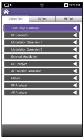
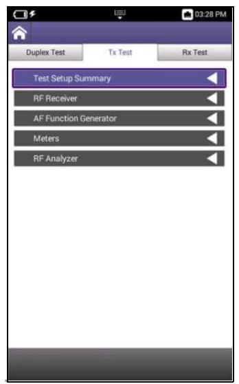
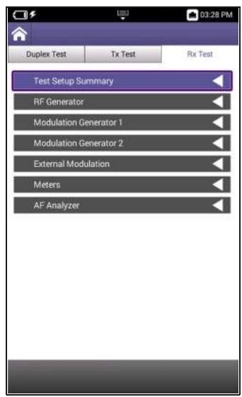
Figure 5-1 RF Test Mode Menus
5.2.1 RF Test Modes of Operation
Each RF Test mode supports functions specific to the selected mode of operation. For example, Rx Test Mode contains parameters necessary to test the receive performance of the DUT. Figure 5-1 provides a visual reference to the functions supported in each mode of operation.
Duplex Test Mode
Duplex Test mode supports full duplex capabilities, providing simultaneous access to both RF Generator and RF Receiver functions. Duplex mode would typically be used to test radios that are capable of duplex operation.
Tx Test Mode
Tx (Transmit) Test mode provides access to the instrument's RF Receiver functions. Tx Test Mode could be used to evaluate radios that are only capable of transmit operation.
Rx Test Mode
Rx (Receive) Test mode provides access to the instrument's RF Generator functions. Rx Test mode could be used to evaluate radios that are only capable of receive operation.
5.2.2 Test Setup Summary Panel
The Test Setup Summary panel displays data for generator and receiver functions that are currently active (turned ON). The panel provides quick reference to generator and receiver settings as well as meter readings.
The Test Setup Summary panel is ideal for monitoring a test without jumping back and forth between function panels.
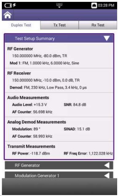
Figure 5-2 RF Test Setup Summary Panel

NOTE
The Test Setup Summary panel does not display information for plot or analyzer functions.
5.2.3 RF Generator
The CX100 RF Generator provides users with a signal source with known parameters. The RF Generator can be used to evaluate the receive performance of the Device Under Test (DUT). The CX100's internal modulation generators can be used in conjunction with the RF Generator to output modulated signals.
5.2.3.1 RF Generator Controls and Settings
The following controls and settings are used to configure the characteristics of the generated RF signal:
Table 5-1 RF Generator Controls and Settings
| Control/Setting | Description |
| Port | This menu selects the RF Generator output connector. • The DUplex connector should be selected as the RF output connector when the lowest level of RF Generator output is needed. • The ANT/SWR connector should be selected as the RF output connector to output high power RF signals. |
| NOTE When the ANT/SWR connector is selected as the RF output connector, the system disables the connector's receive capabilities. | |
| Frequency | This field defines the frequency of the RF Generator signal. The RF Generator Frequency should be set to a value appropriate for the test being performed and to the receive frequency range of the DUT. |
| Frequency Offset Field | Frequency Offset is only supported in Duplex Test Mode. The Frequency Offset field defines the amount by which the RF Generator frequency is shifted when the signal is produced. A frequency offset may be applied to an RF signal to reduce possible interference with other transmitters, or to remove phase noise when performing certain types of measurements. The Frequency Offset field is disabled when the Offset soft-key is set to OFF. When the Offset soft-key is set to ON the following occurs: • The Frequency Offset field updates to an editable field. • The Frequency field updates to a ready only field. When a frequency offset value is entered, the RF Generator Frequency field updates to show the RF Generator frequency with the offset applied. |
| Output Level | This field defines the output level of the RF Generator. The RF Generator Output Level field should be set to a value appropriate for the receive capabilities of the DUT. |
| ATTENTION The output level of the RF Generator should not exceed the approved rating for the input port selected on the receiver. | |
| Offset Soft-key | The Offset soft-key is an on/off toggle soft-key that is used to apply an offset value to the generator frequency. See the Frequency Offset Field description for information. |
| Output Soft-key | The Output soft-key turns the RF Generator on and off. |
5.2.3.2 Configuring the RF Generator
The RF Generator should be configured according to the capabilities of the receiver. Refer to the receiver's input ratings to ensure the output level of the RF Generator does not exceed the operational capabilities of the receiver.
Configure RF Generator Parameters
- Open the RF Generator panel.
- Define the RF Generator Frequency.
- Define the RF Generator Level.
Apply an RF Frequency Offset
- Set the Freq Offset soft-key to ON.
- Define the RF Generator Frequency Offset value.
- The RF Generator Frequency field updates to display the frequency with the offset applied (e.g. 3,001.00 MHz).

NOTE
Frequency Offset field is only supported in Duplex Test mode of operation.
To Output the RF Signal
- Change the RF Gen soft-key to ON.
- The CX100 is now generating an RF signal.
5.2.4 Modulation Generator
The CX100 supports two internal modulation generators which utilize the instrument's RF generator to output modulated signals. The modulation generators function independently from one another, making the CX100 capable of supporting the simultaneous output of two different modulation types. For example, Modulation Generator 1 can be configured to output an AM signal, while Modulation Generator 2 can be configured to output an FM signal.

NOTE
The CX100 only supports one modulation generator when Digital is selected as the Modulation Type. When Digital Modulation is selected as the modulation type on one of the modulation generators, the fields and controls on the other modulation generator are disabled.
5.2.4.1 Modulation Generator Controls and Settings
The following controls and settings are used to configure the characteristics of the outgoing modulated signal that is applied to the carrier frequency (RF generator signal).
Table 5-2 Modulation Generator Controls and Settings
| Control/Setting | Description |
| Modulation Type | The (Modulation) Type menu selects the type of modulation to be applied to the generated signal. The parameters that must be configured to produce a modulated signal are based on the type of modulation selected. • None: No parameters • FM: Deviation, Rate, Waveform • AM: Rate, Depth, Waveform • AM USB/LSB: Rate, Waveform • Digital: File Selection |
| AM or FM Rate | AM or FM Rate defines the rate at which the waveform is varied (modulated) when applied to the carrier frequency. |
| AM Depth | AM Depth defines the a percent by which the modulated waveform varies from the carrier amplitude. |
| FM Deviation | FM Deviation defines the frequency by which the modulated waveform varies from the carrier frequency. |
| Waveform | Waveform selects the shape of the modulated waveform that is being applied to the carrier frequency. |
| File Selection | The File Selection field is enabled when Digital modulation type is selected. The field is used to select a pre-recorded digital modulation file which is applied to the carrier frequency. |
| Mod “x” On/Off Soft-key | The Mod 1 and Mod 2 soft-key turns the corresponding modulation generator on and off. Each modulation generator is controlled independently from the other. |
The CX100 supports the use of an external modulation source for some modulation types (i.e., AM, FM). The instrument must be properly configured to receive a valid incoming audio signal in order to use external modulation.
5.2.4.2 Configuring the Modulation Generator
This section provides instructions to configure the CX100 to output a modulated signal.
Configure RF Generator
- Open the RF Generator panel.
- Define the RF Generator Frequency to which the modulated signal will be applied.
- Set the RF Generator Level to the desired value.
Configure Modulation Characteristics
- Open the Modulation Generator 1 panel.
- Select the Modulation Type.
- Configure modulation parameters.
- Turn Mod Gen 1 or Mod Gen 2 soft-key ON.
To Output the RF Signal
- Select the RF Generator panel.
- Turn the RF Gen soft-key to ON.
- The CX100 is now generating a modulated signal.
5.2.4.3 External Modulation Generator Controls and Settings
The following controls and settings are used to configure the characteristics of the external modulated signal that is being received by the CX100:
Table 5-3 External Modulation Controls and Settings
| Control/Setting | Description |
| Modulation Type | The external modulation parameters that must be configured depend on the type of modulation selected. • None: No parameters • AM: Rate (%), Coupling • FM: Deviation (kHz), Coupling |
| Rate (AM) | Defines the rate at which the waveform is varied (modulated) when applied to the carrier frequency. |
| Deviation (FM) | FM Deviation defines the frequency by which the modulated waveform varies from the carrier frequency. |
| Coupling | Coupling selects how any unwanted AC/DC components are filtered from the received signal. AC Coupling AC coupling filters the DC signal component out of a signal that contains both AC and DC components. The DC component of a signal acts as a voltage offset so removing the component may increase the resolution of signal measurements. DC Coupling DC coupling does not filter components from the signal; both AC and DC signal components are therefore present in the signal. DC coupling is typically used when any offset voltage present is <±100 mV or if the DC content of the signal is important. |
| Mod Ext On/Off Soft-key | The Mod Ext soft-key turns the external modulation generator on and off. |
5.2.5 RF Receiver
The RF Receiver controls and settings are used to determine how the instrument processes an incoming signal. In order to obtain accurate test and measurement results, RF Receiver parameters must be set according to the known characteristics of the incoming signal.
The RF Receiver Port, Frequency, Reference Level and External Attenuator parameters apply to all types of incoming signals. There are additional parameters that must be configured depending on the type of modulation that has been applied to the incoming signal. The modulation type that is selected from the RF Receiver Demodulation Type menu enables the parameters applicable to each modulation type.
Input Overload Caution

CAUTION
Do not overload input connectors. Refer to product labeling or product specifications for maximum input ratings.
5.2.5.1 RF Receiver Controls and Settings
The following controls and settings are used to configure the CX100 RF Receiver. The RF Receiver should be configured according to the expected characteristics of the incoming signal.
Table 5-4 RF Receiver Controls and Settings
| Control/Setting | Description |
| Port | The RF Receiver Port menu selects the input connector at which the incoming signal is being received. This setting should be selected according to the properties of the incoming signal and the requirements of the test being performed.ANT/SWRANT/SWR should be selected for performing high sensitivity, low power measurements. When ANT/SWR is selected, the RF Receiver's pre-amplifier is available. See section , “PreAmp On/Off Soft-key”, on page 5-13 for information.DUPLEXDUPLEX should be selected for receiving high power signals.See “Input Overload Caution” on page 5-10.If the test involves a high power incoming signal that exceeds the input ratings of the RF Receiver input connectors, use an external attenuator (see “External Attenuator” description below). |
| Frequency | The RF Receiver Frequency should be set to match the frequency being transmitted by the DUT. |
| External Attenuator | The External Attenuation field makes adjustments in signal processing to account for the use of an attenuator pad or adapter. The External Attenuator field should be set to a value appropriate to the attenuator pad or adapter being used. |
| Reference Level | Reference Level defines the signal level in relation to the RF Input of the incoming signal; the field should be set according to the expected power level of the incoming signal. |
| Demodulation Type | The Demodulation Type selects the type of modulation that has been applied to the incoming signal, providing controls and parameters necessary to separate the data from the carrier signal. The demodulation controls and parameters that are available are determined by the following: • The type of signal that is being demodulated • The type of AF Filter that is selected to process the incoming signal • The selected filter characteristics (when applicable) • The De-Emphasis setting (when applicable) |
| IF Bandwidth (BW) | IF BW menu selects the IF detection bandwidth. Select the IF bandwidth appropriate for the characteristics of the incoming signal. |
| Δ | A lower bandwidth reduces the interference caused by powerful narrow-band transmitters, therefore, select the lowest bandwidth possible to suit the characteristics of the incoming signal. |
| AF Filters | The parameters that are available for configuring AF Filters depends on the type of filter selected. |
| Low PassWhen Low Pass is selected, the Audio Low Pass and De-Emphasis parameters are enabled. | |
| High PassWhen High Pass is selected, the Audio High Pass and De-Emphasis parameters are enabled. | |
| Band PassWhen Band Pass is selected, the Low Pass Corner Frequency, High Pass Corner Frequency, and De-Emphasis parameters are enabled. | |
| PsophometricWhen Psophometric is selected, the Psophometric (Weight) and De-Emphasis parameters are enabled. | |
| Audio Low Pass | A low-pass filter (LPF) passes signals with a frequency lower than a selected cutoff frequency. The Audio Low Pass filter selects the highest frequency that is allowed to pass through the AF filter; frequencies above the selected frequency are cut off. |
| Audio High Pass | A high-pass filter (HPF) passes signals with a frequency higher than a selected cutoff frequency. The Audio High Pass filter selects the lowest frequency that is allowed to pass through the AF filter; frequencies below the selected frequency are cut off. |
| Audio Band Pass | Audio Band Pass enables the low pass and high pass corner frequency fields which allow the user to define a frequency band to allow signals within a certain frequency band to pass, while blocking signals with frequencies on the outside of the band. |
| Low Pass Corner FrequencyThe Low Pass Corner Frequency defines the lower end of the frequency band filter. Any signal that is detected that falls below this frequency is filtered out of the incoming signal. | |
| High Pass Corner FrequencyThe High Pass Corner Frequency defines the upper end of the frequency band filter. Any signal that is detected that is above this frequency is filtered out of the incoming signal. |
Table 5-4 RF Receiver Controls and Settings (Continued)
| Control/Setting | Description | ||
| Psophometric | Psophometric filters are typically used when measuring the residual noise in audio equipment. The Psophometric filter is included in the signal path to emphasize the audible parts of the signal and attenuate signal components that contribute less to perception of loudness. CCITT and C-message (C-MSG) weighting filters are bandpass filters used to measure audio-frequency noise on telephone circuits.C-MSG FilterThe C-MSG is used for voice, audio, and telecommunication applications in the U.S.CCITTThe CCITT filter is used for international telephone circuits.De-Emphasis | Psophometric filters are typically used when measuring the residual noise in audio equipment. The Psophometric filter is included in the signal path to emphasize the audible parts of the signal and attenuate signal components that contribute less to perception of loudness. CCITT and C-message (C-MSG) weighting filters are bandpass filters used to measure audio-frequency noise on telephone circuits.C-MSG FilterThe C-MSG is used for voice, audio, and telecommunication applications in the U.S.CCCITTThe CCITT filter is used for international telephone circuits.The De-Emphasis filter attenuates signal components by the amount by which they have been amplified (PreAmp is turned ON). In some cases, the combined use of the pre-amp and de-emphasis filter may improve signal to noise ratio of an incoming signal.When the Autotune soft-key is pressed, the CX100 sets the RF Receiver Frequency to the strongest signal detected at the active RF Input connector.PreAmp On/Off Soft-key | When the Autotune soft-key is pressed, the CX100 sets the RF Receiver Frequency to the strongest signal detected at the active RF Input connector.The RF Receiver's pre-amplifier is available for use when the RF Receiver Port is set to ANT/SWR. This soft-key determines whether or not the pre-amplifier is included (ON) in the input signal path.The pre-amplifier (PreAmp) is typically used to boost weak incoming signals to eliminate noise and produce a clean signal that is strong enough to be processed. |
5.2.5.2 Configuring the RF Receiver
To Configure the RF Receiver
- Open the RF Receiver panel.
- Connect the incoming RF Signal to the RF Receiver Port appropriate for the characteristics of the incoming signal.
- Select the RF Receiver Port selected in step 2.
- Set the RF Frequency to the frequency of the incoming signal.
- Set the RF Frequency Reference Level to the power level of the generator/radio.
- Set the RF Receiver Demodulation Type to the modulation type of the incoming signal.
5.2.6 AF Function Generator
The CX100 contains two audio function (AF) generators that are capable of supporting the simultaneous output of two signals of different frequencies, shape and power.
The Settings soft-key opens a configuration menu that accesses controls and settings that are used to configure the parameters of the generated audio signal. See Table 5-5, "AF Generator Controls and Settings," on page 5-14 for a description of these settings.
5.2.6.1 AF Generator Controls and Settings
The following controls and settings are used to configure the characteristics of the generated audio signal:
Table 5-5 AF Generator Controls and Settings
| Controls/Settings | Description |
| Frequency | This field defines the frequency of the outgoing waveform. Each function generator can be configured to produce a waveform at a different frequency. |
| Level Type | Level Type selects the manner in which the level is calculated and applied to the outgoing signal. VPP Peak to Peak Voltage (VPP) is measured from the top of the waveform to the bottom of the waveform. Vpp is typically used when working with instantaneous voltages. Vrms Root mean squared voltage (Vrms) is a calculation of Vpp that yields the equivalent DC voltage that would deliver the same energy to the load. Vrms is typically used when there is a requirement to calculate average power in an AC circuit. |
| Level | The Level field defines to output level of the signal in either Vpp or Vrms as selected in the Level Type field. |
| Waveform | The Waveform field selects the type of waveform to be generated by the function generator. |
| Encode Type | Encoding is accessed from the Settings soft-key. Encoding Type selects the protocol standard that is used to format that data that is included in the generated signal. Contact VIAVI for information about support for different types of signal encoding. |
| Coupling | Coupling is accessed from the Settings soft-key. Coupling selects how unwanted AC/DC signal components are filtered from the received signal. AC Coupling AC coupling filters the DC signal component out of a signal that contains both AC and DC components. The DC component of a signal acts as a voltage offset so removing the component may increase the resolution of signal measurements. DC Coupling DC coupling does not filter components from the signal; both AC and DC signal components are therefore present in the signal. DC coupling is typically used when any offset voltage present is <±100 mV or if the DC content of the signal is important. |
| Settings Soft-key | The Settings soft-key opens a menu that accesses the following controls and settings (described above): • Encode Type • Coupling |
| AF Gen “x” Soft-key | The AF Gen 1 and AF Gen 2 soft-keys turn the corresponding AF Generator on and off. |
5.2.6.2 Configuring the AF Function Generator
To Configure the CX100 AF Function Generator:
- Open the AF Function Generator panel.
- Set Coupling to desired setting.
- Set Frequency for AF Generator 1 and or 2.
- Select Level Type for AF Generator 1 and or 2.
- Set Level for AF Generator 1 and/or 2.
- Select Sine for AF Generator 1 and or 2 Waveform.
- Enable to AF Generator(s) being used.
- AF signal is now being generated at the Audio Out connector.
5.2.7 RF Test Meters
The Meters panel displays measurement data for the device Under Test (DUT). The types of meters that are active on the Meters panel depend on the following selections:
RF Test mode that is selected.
- Modulation type selected from the RF Receiver Demodulation Type menu. See section, "Demodulation Type", on page 5-11 for information.
- User selections such as the type of noise measurement, or the type of power measurement to be performed.
5.2.7.1 Meter Panel Layout
The Meters panel is a drop-down panel that contains meter "blocks" that are grouped according to meter type. Each meter is displayed under the appropriate meter heading as a separate block; each meter block contains the following information (Figure 5-3):
- Meter Name: displayed top, center of the meter block
- Meter reading: displayed centered in the middle of the meter block
UOM: unit of measurement (UOM) is displayed centered below the meter reading
Measurement type: displayed in the lower right corner of the meter block - Offset Applied Indicator: displayed on the power measurement meters when external attenuation is applied.
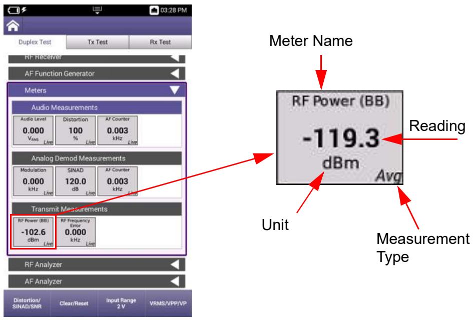
Figure 5-3 Meter "Block" Content Diagram
5.2.7.2 Meter Soft-key Panel
The contents of the Meter soft-key panel is determined by the selected meter group. To activate a soft-key panel, select the group title bar (e.g. Audio Measurements or Transmit Measurements). The contents of the soft-key panel will update to display soft-keys that support functions applicable to the selected meter group.
5.2.7.3 Meter Configuration Window
Each meter requires specific controls and settings necessary to configure how measurements are performed and how the results are displayed on the UI. These controls and settings are located in meter configuration windows. Meter configuration windows are opened by pressing and holding a meter block.
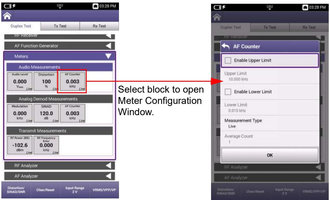
Figure 5-4 Opening Meter Configuration Window
The contents of meter configuration windows varies according to the settings required to perform each measurement. This section describes meter limits and measurement type settings, which are supported in some capacity on each meter. Other meter parameters are described in the following sections:
5.2.7.4 Audio Measurements 5-20
5.2.7.5 Analog Demod Measurements 5-21
5.2.7.6 Digital Demod Measurements. 5-23
5.2.7.7 Transmit Measurements 5-29
Meter limits are used to define pass/fail criteria for measurements. CX100 meters support upper and lower limits as appropriate for the measurement. When limits are enabled for a meter, CX100 meters provide a visual indicator of pass/fail status: the background color of the meter block changes to indicate reading status as described below in Table 5-6.
Table 5-6 Meter Limit Status Indicators
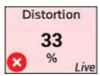
Example 1
Red background and fail icon indicate the following condition:
- Above Upper Limit
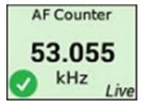
Example 2
Green background and pass icon indicate the following conditions:
Below upper limit
Above lower limit
- Within upper and lower limit(s)
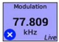
Example 3
Blue background and fail icon indicate the following condition:
Below lower limit
5.2.7.3.1.A Upper Limits
The Upper Limit field sets a maximum acceptable reading for a specific measurement. The upper limit value must be greater than the value defined in the lower limit field, even when the lower limit is not enabled.
When a measurement exceeds the enabled upper limit value, the measurement block turns red and the × fail icon is displayed (Example 1).
When readings are under a defined Upper Limit, or within enabled upper and lower limits, the measurement block turns green and the pass icon is displayed (Example 2).
5.2.7.3.1.B Lower Limits
The Lower Limit field sets a minimum acceptable reading for a specific measurement. The lower limit value must be lower than the value defined in the upper limit field, even when the upper limit is not enabled.
When a measurement falls below the enabled lower limit value, the measurement block turns blue and the × fail icon is displayed (Example 3).
When readings are above a defined lower limit, or within enabled upper and lower limits, the measurement block turns green and the pass icon is displayed (Example 2).
5.2.7.3.2 Meter Measurement Types
Each meter supports live, maximum, minimum and average measurements. A small text indicator is located on each meter block which indicates the measurement type being displayed on the meter.
Live Measurement
When Live is selected, the meter displays the measured value of the signal at that given point in time. The meter updates continuously as long as the device is receiving an incoming signal.
Max Measurement
When Max is selected, the meters displays the highest reading detected at that point in time. The meter updates when/if a reading is detected that is higher than the currently displayed measurement.
Min Measurement
When Min is selected, the meters displays the lowest reading detected at that point in time. The meter updates when/if a reading is detected that is lower than the currently displayed measurement.
Average Measurement
When Average is selected, a field is enabled which is used to define the number of readings acquired to calculate the average measurement. The meter reading updates each time the defined number of measurements has been processed.
5.2.7.4 Audio Measurements
Audio measurements are supported in Duplex Test and Rx Test modes of operation. The CX100 contains the following Audio meters:
Audio Level Meter
The Audio Level meter indicates the signal voltage or power of the received audio signal. The measurement is used to evaluate the power performance of the transmit device.

Offset Applied Indicator
An offset indicator is displayed on the Audio Level meter measurement meters when external attenuation is applied.
(Audio) Distortion Meter
The Distortion meter is used to detect and isolate any frequencies that are causing distortion on the incoming audio signal. The Distortion meter displays the difference between the incoming audio signal in relation to the transmitted signal. The differences detected are a result of extraneous signals present in the audio signal (i.e., noise, external signals).
(Audio) SINAD Meter
SINAD measurements are typically used to determine receiver sensitivity, but they can also be used to determine how a transmit signal is degraded by noise and distortion. The SINAD Meter displays the ratio Signal + Noise + Distortion divided by the sum of Noise + Distortion, the result of which is displayed in dB.
(Audio) SNR Meter
Signal to Noise (SNR) measurements compare the level of a desired signal to the level of background noise. SNR is defined as the ratio of signal power to the noise power.
AF Counter
The AF Counter measures the number of oscillations present in the received audio signal. The AF Counter is used to perform tasks such as measuring the frequency of a carrier signal or measuring the frequency accuracy of the incoming signal.
5.2.7.4.1 Audio Meter Controls and Settings
The audio meters supports user selectable measurement types which are described in section 5.2.7.3.2, on page 5-19 and upper and lower limits which are described in section 5.2.7.3.1, on page 5-18. The audio meters also contain the follow controls and settings:
Table 5-7 Audio Meter Controls and Settings
| Control/Setting | Description |
| “Noise Meter”Soft-key | This soft-key selects the type of noise measurement to be performed, Distortion or SINAD. The noise meter displayed in the Meter panel is selected using this soft-key. |
| Clear/ResetSoft-key | Clears meter readings, resets the measurement meter, then resumes data acquisition. |
| Input RangeSoft-key | This toggle key switches between Audio Level Input Range. |
| Level UnitsSoft-Key | This toggle key switches the Audio Level meter between Vrms, VPP and VP units of measurement. |
5.2.7.5 Analog Demod Measurements
Analog demodulation measurements are supported in Duplex Test and Tx Test modes of operation. The CX100 contains the following analog demodulation meters:
Modulation Meters
Amplitude Modulation (AM) Meter
The AM meter displays the percentage by which the amplitude of the incoming signal varies from the amplitude of the transmitted signal. The AM meter is displayed when the RF Receiver Demodulation Type is set to AM (see "Demodulation Type" on page 5-11).
Frequency Modulation (FM) Meter
The FM meter displays the frequency by which the frequency of the incoming signal varies from the frequency of the transmitted signal. The FM meter is displayed when the RF Receiver Demodulation Type is set to FM (see "Demodulation Type" on page 5-11).
(Demod) Distortion Meter
The Distortion meter is used to detect and isolate any frequencies that are causing distortion on the incoming RF signal. The Distortion meter displays the difference between the incoming signal in relation to the transmitted signal. The differences detected are a result of extraneous signals present in the RF signal (i.e., noise, external signals).
(Demod) SINAD Meter
SINAD measurements are typically used to determine receiver sensitivity, but they can also be used to determine how a transmit signal is degraded by noise and distortion. The SINAD meter displays the ratio Signal + Noise + Distortion divided by the sum of Noise + Distortion, the result of which is displayed in dB.
(Demod) SNR Meter
Signal to Noise (SNR) measurements compare the level of a desired signal to the level of background noise. SNR is defined as the ratio of signal power to the noise power.
AF Counter
The AF Counter measures the number of oscillations present in the received signal. The AF Counter is used to perform tasks such as measuring the frequency of a carrier signal or measuring the frequency accuracy of the incoming signal.
5.2.7.5.1 Analog Demod Meter Controls and Settings
Demod meters supports user selectable measurement types which are described in section 5.2.7.3.2, on page 5-19 and upper and lower limits which are described in section 5.2.7.3.1, on page 5-18. Demod meters also contain the following controls and settings:
Table 5-8 Demod Meter Controls and Settings
| Control/Setting | Description |
| “Noise Meter”Soft-key | This soft-key selects the type of noise measurement to be performed, Distortion or SINAD. The noise meter displayed in the Meter panel is selected using this soft-key. |
| Clear/ResetSoft-key | Pressing this soft-key clears meter readings, resets the measurement meter, then resumes data acquisition. |
5.2.7.6 Digital Demod Measurements
The CX100 contains a Vector Signal Analyzer (VSA) that processes and demodulates digital data, which is then sent to the device's Digital Demod meters. The Digital Demod meters are used to identify any impairments in the digital signal that may have been introduced by the analog parts of the digital transmitter. More common impairments that negatively impact the performance of a digital modulator are timing drift, frequency offset and amplitude imbalance.
The CX100's VSA estimates certain values in relation to the impairments in the received signal. In order to estimate the impairments, the VSA uses a perfect received signal, called a reference signal, and compares the reference signal to the actual received signal, called the measured signal. Figure 5-5 on page 5-24 shows a high level block diagram of the VSA's main components.
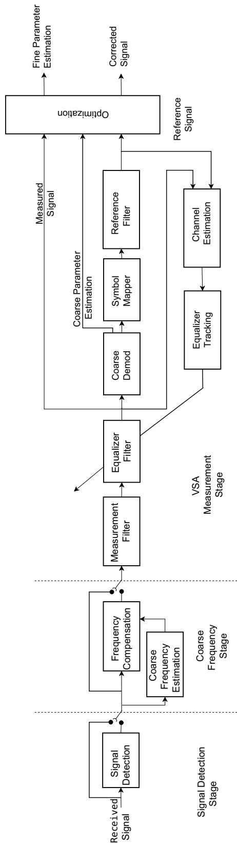
Figure 5-5 VSA Block Diagram
5.2.7.6.1 Digital Demod Meters
The Digital meters are available in Duplex Test and Tx Test Mode when the RF Receiver Demodulation Type is set to Digital (see "Demodulation Type" on page 5-11). The CX100 supports the following digital meters:
(Digital) Power
The (Digital) Power meter is used to evaluate the transmit performance of a digital transmitter.
Error Vector Magnitude (EVM)
Error Vector Magnitude (EVM) is a measure of modulation quality and error performance of a wireless communication systems. The is used to evaluate the performance of a digital transmitter or receiver for the evaluation of software-defined radios (SDRs).
Frequency Offset
Frequency Offset is used to evaluate the frequency accuracy of the signal. The meter indicates the difference between the DUT transmitted signal and the defined RF frequency.
5.2.7.6.2 Digital Meter Controls and Settings
The Digital meters support user selectable measurement types which are described in section 5.2.7.3.2, on page 5-19 and upper and lower limits which are described in section 5.2.7.3.1, on page 5-18. The Digital meters also contain the following controls and settings:
Table 5-9 Digital Meter General Settings
| Control/Setting | Description |
| Center Frequency | The Center Frequency field is a read only field that indicates the RF Receiver Frequency setting. This value should be set to the expected frequency of the received signal. See Table 5-4, “RF Receiver Controls and Settings,” on page 5-10 for information. |
| Reference Level | The Reference Level field is a read only field that indicates the RF Receiver Reference Level setting. This value should be set to the expected power level of the transmitter. See Table 5-4, “RF Receiver Controls and Settings,” on page 5-10 for information. |
| Coarse Search Frequency | The Coarse Search Frequency setting determines whether or not the digital receiver searches for the received signal if the signal is not present at the defined Center Frequency. When this is enabled, the coarse frequency estimation block of the VSA computes a rough estimation of the frequency offset of the received signal and searches for the signal within the estimated offset range. |
Table 5-10 Digital Meter Modulation Settings
| Control/Setting | Description |
| Modulation Type | This menu selects the digital modulation type of the signal being analyzed. |
| Modulation Order | This field defines the number of possible symbols in the constellation of the modulation. |
| Symbol Rate | This field defines the number of symbols per second of the received signal. |
| Oversampling | This field defines the number of samples per symbol to analyze the signal. |
| Number of Symbols | This field defines the number of symbols used to calculate the parameters in each block of data. |
Table 5-11 Digital Meter Equalizer Settings
| Control/Setting | Description |
| Gain | The equalizer gain is used to adjust the coefficients of the equalizer filter. |
| Equalizer Length | This field defines the length in number of taps of the equalizer filter. |
| Equalizer Plot Length | This field defines the number of points of the spectrum plot of the channel estimated by the equalizer. |
5.2.7.6.3 Digital Filter Types
The CX100 Digital Demod filters are used to limit bandwidth and reduce inter-symbol interference (ISI). The CX100's digital demodulator produces a measured signal and a reference signal. The measured signal is the signal that results from demodulating the waveform; the reference signal is the signal that results from demodulating a signal that contains no errors.
The Digital Filter should be configured based on how the radio/radio system under test performs filtering. Filtering will be performed at the transmitter, at the receiver, or distributed between the transmitter and the receiver.
Reference Filter
The Reference Filter is the combined response of the transmit and measurement filter. This filter is applied to the reference signal.
Measurement Filter
The Measurement Filter is the shaping filter in the receiver that is applied before demodulation. For some filters, this filter reduces the inter-symbol interference (ISI). For other filters, this filter reduces energy from other signals.
The following settings are available for the digital filters:
Table 5-12 Digital Measurement Filter Settings
| Control/Setting | Description |
| Type | The Digital meters support the following meter types: Reference Filter • No Filter: No filter is included in the receive path. • Raised Cosine: Should be used in systems which perform all the filtering in the transmitter. Measurement Filter • No Filter: No filter is included in the receive path. • Square Root Raised Cosine: Should be used to test systems that perform partial filtering in the transmitter and partially filtering in the receiver. |
| Roll-off Factor | Defines the amount of bandwidth allowed in relation to the selected filter. |
| Filter Length | Defines the length of the measurement or reference filter. |
5.2.7.6.4 Digital Equalizer Filter
The equalizer is a complex linear Finite Impulse Response (FIR) filter that compensates the channel; the number of "taps" is flexible. The FIR filter is estimated by the Channel Estimation block of the VSA (see Figure 5-5 on page 5-24).
The Equalize soft-key is used to include the FIR filter in the receive path. When the Equalizer soft-key is pressed, the UI updates to display another set of soft-keys, referred to as the Equalizer soft-key panel, which control the states of the equalization filter. The contents of the Digital Equalizer soft-key panel change based on the state of the equalizer. For example, Freeze Equalizer and Reset Equalizer are not enabled until the equalizer is ON (in learning state) and when Equalizer Learn is pressed, the soft-key updates to a status key.
Table 5-13 Equalizer Soft-key Panel
| Soft-key | State/Description |
| Equalizer Learn Soft-key | When the Learning soft-key is selected, the following actions occur: • The equalizer learning process is initiated. • The soft key panel reverts to the Digital Demod Measurements soft-key panel. • The status line on the Equalizer soft-key updates to show Equalizer Learning. In the Learning State, the options are to freeze, reset or stop the equalizer process. |
| Freeze Equalizer Soft-key | When the Freeze soft-key is pressed, the following actions occur: • The equalizer filter applies the last taps values that were estimated in the learning state. • The soft key panel reverts to the Digital Demod Measurements soft-key panel. • The status line on the Equalizer soft-key updates to show Equalizer Frozen. Actions available from this state are Learn, Reset or Off. |
| Reset Equalizer Soft-key | When the Reset soft-key is pressed, the following actions occur: • The equalizer filter is set to an impulse response and then goes to the previous state. • The soft key panel reverts to the Digital Demod Measurements soft-key panel. • The status line on the Equalizer soft-key updates to show Equalizer Learning. Actions available from this state are Freeze, Reset or Off. |
| Equalizer Off Soft-key | When set to OFF, the equalizer filter is bypassed. The only action available from the OFF state is Learning; all other soft-keys are disabled until the Equalizer Learn soft-key is selected. |
5.2.7.7 Transmit Measurements
Transmit measurements are used to evaluate the performance of the DUT transmitter. These meters are available in Duplex Test and Tx Test Mode. The CX100 supports the following transmit measurements:
5.2.7.7.1 RF Frequency Error
The RF Frequency Error meter measures the frequency error of the received signal in relation to the defined RF Receiver Frequency; this meter is used to evaluate the accuracy of the DUT transmitter. The CX100's RF Receiver Frequency must be set to the expected transmit frequency of the UUT in order to obtain valid RF Frequency Error measurements.
The RF Frequency Error meter supports user selectable measurement types which are described in section 5.2.7.3.2, on page 5-19 and lower limits which are described in section 5.2.7.3.1, on page 5-18.
5.2.7.7.2 RF Power Meter
The RF Power meter is used to evaluate the RF transmit performance of a DUT, most commonly to determine if the DUT's output power is meeting specification.
The RF Power meter supports user selectable measurement types which are described in section 5.2.7.3.2, on page 5-19 and lower limits which are described in section 5.2.7.3.1, on page 5-18. The RF Power meter also contains the following controls and settings: y
Table 5-14 RF Power Meter Controls and Settings
| Control/Setting | Description |
| Receiver | This field is used to compensate for the use of an external attenuator for high power transmitters. RF Power meter readings are compensated by the defined external attenuation value. This value should be defined as a negative value only. |
| External Attenuator | |
| Normalize | When the Normalize soft-key is pressed, the system zeroes out the RF Receiver signal path, removing any residual power from the RF path which eliminates the system's frequency response error. |
| Soft-key |
The RF Power meter uses the following status indicators:
Offset Applied Indicator

An offset indicator is displayed on the RF Power meter when external attenuation is applied. RF Offsets are applied on the RF Generator panel (see "Offset Soft-key" on page 5-6).
Normalize Indicator

An Attention indicator is displayed on the Normalize soft-key when normalize needs to be performed. When this condition occurs, Normalize should be performed to ensure accurate measurements.
5.2.8 Digital Plots Panel
The Digital Plots panel is used to evaluate the quality of the received digital signal. The Digital Plots panel is enabled when the RF Receiver Demodulation Type is set to receive digital signals (see "Demodulation Type" on page 5-11). The instrument supports a variety of digital plots which are dependent on the characteristics of the digital signal.
5.2.8.1 Constellation Plot
The IQ Domain, Constellation Plot displays the constellation points of the digital signal. This plot is used for evaluating signal distortion and noise.
The Display Settings soft-key opens a menu that contains controls and settings that affect display layout and manage how traces are displayed on plot field. See section 5.2.8.1.2, "Constellation Plot Controls and Settings", on page 5-31 for a description of these settings. Read-only digital meter fields are displayed above the plot field for reference purposes; the meters are configured on the Meters panel (see section 5.2.7.6, on page 5-23).
5.2.8.1.1 Constellation Plot Soft-key Panel
The Constellation Plot soft-key panel contains the following controls:
Table 5-15 Constellation Plot Soft-key Panel
| Control/Setting | Description |
| Display Settings Soft-key | The Display Settings soft-key opens a menu that contains controls and settings that affect display layout and manage how traces are displayed on plot field. See section 5.2.8.1.2, “Constellation Plot Controls and Settings”, on page 5-31 for a description of these settings. |
| Clear/Reset Soft-key | Cleared captured trace data from the plot field and resets measurement meters that are located above the plot field, then resumes data acquisition. |
| Pause/Resume Soft-key | When the signal plot is displayed on the UI, the signal trace is active by default. Pressing the Pause soft-key temporarily halts data updates to the UI. When this occurs, the soft-key updates to the Resume soft-key.When the signal plot is paused, data that is being acquired is stored in the system's data acquisition buffer, when the Resume soft-key is pressed, the data being stored in the buffer is released and sent to the UI. |
5.2.8.1.2 Constellation Plot Controls and Settings
The following settings are used to configure how the trace is displayed on the plot field:
Table 5-16 Constellation Plot Controls and Settings
| Control/Setting | Description |
| Type | Type is accessed from the Display Settings soft-key. The Type menu selects the measurement plot that will be displayed on the screen. The contents of this menu are determined by the type of digital signal that is selected on the RF Receiver panel. |
| Persistence | The Persistence field is accessed from the Display Settings soft-key. The persistence setting specifies how many trace plots are shown simultaneously on the display field. The selectable range is 1 to 10. Selecting 1 means that only one burst or time slot is displayed on the display field. Selecting 10 means the last 10 bursts or time slots are displayed simultaneously on the display field. |
5.2.9 RF Analyzer
The RF Analyzer is used to evaluate the receive performance of the device under test (DUT). The RF Analyzer is an asynchronous, swept analyzer that displays the spectrum of the RF signal received by the test set over a 5 MHz bandwidth. The source of the signal is from the DUT, and the signal is routed through the test set's receiver chain, therefore the RF Analyzer is dependent on the receiver for receive settings such as connector selection, attenuation and center frequency.

NOTE
The RF Analyzer is not available when the RF Receiver Demodulation Type is set to receive digital signals (see "Demodulation Type" on page 5-11).
5.2.9.1 RF Analyzer Panel Layout
The RF Analyzer panel consists of the following areas or groups of controls and settings:
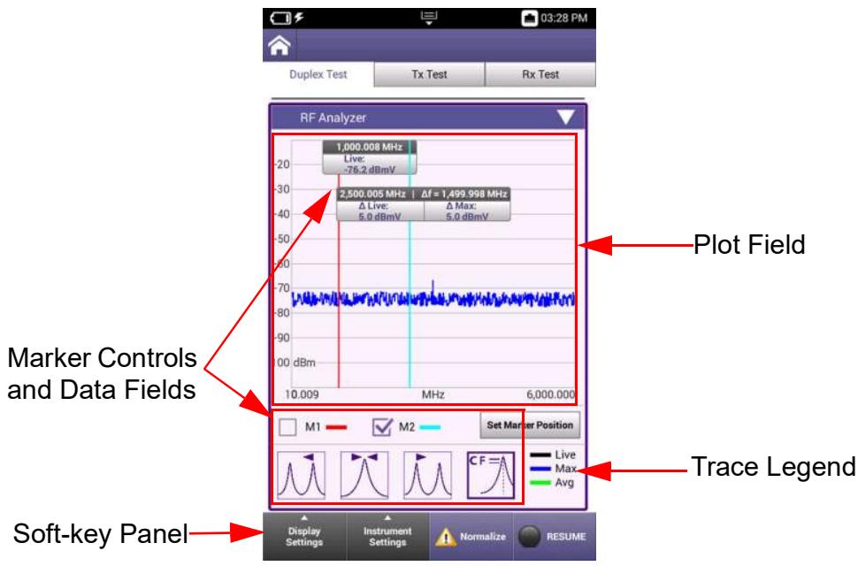
Figure 5-6 RF Analyzer Panel Layout
Plot Field
The plot field displays a visual representation of the received signal. Controls and settings are available that allow the user to adjust settings such as plot scale, modes of operation and the types of traces being displayed on the plot.
See section 5.2.9.3, "RF Analyzer Display Settings", on page 5-34 and section 5.2.9.4, on page 5-36 describe the controls and settings that are supported on the RF Analyzer.
Marker Controls and Data Fields
The RF Analyzer contains a variety of marker functions, controls and settings that allow the user to create custom test scenarios. See section 5.2.9.5, "RF Analyzer Marker Controls", on page 5-39 for a description of Marker controls and settings.
Trace Legend
The trace legend indicates the trace types that are currently active and the color of the line used to represent each trace type. The types of traces that are displayed on the plot field are selected using the Active Trace button located in the Display Settings menu.
Soft-key Panel
The soft-key panel contains controls and settings that are used to configure the RF Analyzer. See section 5.2.9.2, "RF Analyzer Soft-key Panel", on page 5-33 for a description of RF Analyzer softkeys.
5.2.9.2 RF Analyzer Soft-key Panel
The RF Analyzer soft-key panel contains the following controls:
Table 5-17 RF Analyzer Softkeys
| Soft-key | Description |
| Display Settings Soft-key | The Display Settings soft-key opens a menu that contains controls and settings manage how traces are displayed on the plot field.See section 5.2.9.3, “RF Analyzer Display Settings”, on page 5-34 for a description of these settings. |
| Instrument Settings Soft-key | The Instrument Settings soft-key opens a menu that contains controls and settings that define how the RF Analyzer receives and processes an incoming signal.See section 5.2.9.4, “RF Analyzer Instrument Settings”, on page 5-36 for a description of these settings. |
| Normalize Soft-key | TheNormalize soft-key opens a settings window that contains controls and settings which are used to zero out the RF Analyzer signal path, removing any residual power from the RF path which eliminates the system’s frequency response error. |
| Spot Frequency | The Spot Frequency field defines the frequency to be zeroed out. Pressing the RunNormalize soft-key initiates the process. |
| ! normalize | An attention indicator is displayed on theNormalize soft-key when the system detects residual power on the signal path. When this condition occurs,Normalize should be performed to ensure accurate measurements. |
| Pause/Resume Soft-key | When the RF Analyzer is displayed on the UI, the signal trace is active by default. Pressing the Pause soft-key temporarily halts data updates to the UI. When this occurs the soft-key updates to the Resume soft-key. When the Analyzer is paused, data that is being acquired is stored in the system's data acquisition buffer, when the Resume soft-key is pressed, the data being stored in the buffer is released and sent to the UI. |
5.2.9.3 RF Analyzer Display Settings
The Display Settings soft-key opens a menu that contains controls and settings that manage how traces are displayed on plot fields.
Table 5-18 RF Analyzer Display Settings
| Control/Setting | Description |
| Active Trace Button | The Active Trace button opens a window that selects the type of trace(s) to be displayed on the plot field. Multiple traces can be selected at any given time on each plot. • Max: displays highest signal received • Min: displays lowest signal received • Live: displays live signal trace • Average: displays an averaged signal trace; average is defined by the Average Field. |
| Average (Field) | The Average field is enabled when Average is selected as the active trace. The Average field defines the number of traces to be used to calculate an average signal trace. |
| Capture Trace Button | When the Capture Trace button is pressed, a trace is “held” on the display. When more than one trace is active on a plot, only one of the active traces will be captured. When multiple trace types are enabled, traces are captured in the following priority:MAX Priority 1MIN Priority 2Average Priority 3Live Priority 4For example, if Average and Live traces are enabled, the Average trace is captured. If Max and Average traces are enabled, the Max trace is captured.When the Capture Trace button is pressed, the Clear Trace button is enabled which is used to remove a captured trace from the plot field. |
| Clear Trace Button | The Clear Trace button is active when a the Captured Trace button has been pressed and a trace is captured on the plot field. Pressing the Clear Trace button removes the captured trace from the plot field. |
| Save Trace Button | Pressing the Save Trace button displays a window that is used to enter a name for saving a file. The file will be saved to a user defined location. See section 4.2.7, “Specifying File Save Location”, on page 4-8.The Save Trace function saves x,y data in .csv file format. |
| Recall Trace Button | The Recall Trace button displays a file selection box which allows user to recall a stored trace. The stored trace file can be recalled from the device or from a USB device. |
5.2.9.4 RF Analyzer Instrument Settings
The Instrument Settings menu accesses the controls and settings that define how the RF Analyzer receives and processes an incoming signal.
Table 5-19 RF Analyzer Instrument Settings
| Control/Setting | Description |
| Port | The Port menu selects the input connector that is used for analyzing incoming signals.ANT/SWR The ANT/SWR connector should be selected to perform over the air testing using an external antenna or when test parameters require maximum input sensitivity. This connector should be used when analyzing low level RF signals.DUPLEX The DUPLEX connector is a combined (Duplexed) connector that provides an RF generator output connection and an RF receiver input connection. This connector should be used when analyzing high power RF signals. |
| Coupling | The Coupling menu accesses settings that define the Resolution Bandwidth (RBW) and acquisition time that the Analyzer uses to filter the signal. Acquisition time is used in combination with the RBW setting to improve frequency resolution. Acquisition time and RBW bandpass filter should be inversely proportional to one another. Making the acquisition time longer, while keeping the sampling rate the same, results in the ability to use a narrower RBW.Resolution Bandwidth (RBW)RBW filters are the bandpass filters in the IF path that determine the RF noise floor and how close two signals can be and still be viewed separately on the analyzer.A narrower RBW setting more clearly displays close signals as separate signals, however, a narrower bandwidth setting results in a longer sweep time.An RBW setting that is too wide causes signals that are close together to appear as one signal.Auto Mode: system sets RBW to a filter appropriate to the characteristics identified in the received signalManual Mode: allows the user to manually define the RBW. |
| Coupling (cont) | Acquisition TimeAcquisition Time field defines the length of time that samples are acquired from the time domain.Auto Mode: system sets Acquisition time to a value appropriate to the characteristics identified in the received signal as well as the RBW setting.Manual Mode: allows the user to manually define acquisition time. |
| Reference Level | The Reference Level field defines the top value on the plot field's vertical scale. Reference Level can be set to any value within the specified range, but should be set to a value above the expected power level of the incoming signal in order to view the full signal waveform. |
| Frequency Mode | Frequency Mode selects the method used to define the span of the analyzer plot field. Parameters update according to the type of mode selected.Full Span Frequency ModeWhen Full Span is selected, the span defaults to the instrument's full frequency range. The UI updates to display the Start and Stop frequencies as read-only data fields. |
| Center/Span Frequency ModeCenter/Span Frequency mode of operation specifies the center frequency value as well as the frequency span setting.When Center/Span is selected, the UI displays a Center Frequency and Span setting. Center/Span mode uses the sweep Center Frequency value and Span setting to define the frequency span. | |
| Start/Stop Frequency ModeStart-Stop frequency mode of operation defines the sweep start and sweep end frequencies of the swept measurement range.When Start/Stop is selected, the UI displays a Start Frequency and Stop Frequency fields. The sweep start and sweep stop frequencies define the frequency span. | |
| Frequency Mode (cont) | |
| Zero Span Frequency Mode In Zero Span mode the Analyzer does not perform a frequency sweep: it detects the power level at the set frequency. The trace shows detected power against time. When operating in Zero-Span mode, marker position is specified in time. | |
| Amplitude | Amplitude settings affect how the plot field's vertical scaling and how the signal appears when displayed on the plot field. Scale The RF Analyzer uses logarithmic scaling to display the signal amplitude on the analyzer vertical axis. Differences in signal amplitudes are compressed because low amplitude signals are amplified and high amplitude are compressed. This allows signal with widely varying amplitudes to be displayed on the same plot. Log scale is used to view both low amplitude and high amplitude frequencies with same clarity. Vertical Scale Selects the dB division between the vertical scaling on the plot field. |
| Detector Type | The RF Analyzer uses detectors in order to accurately map the correct signal power to the correct frequency point on the display. |
5.2.9.5 RF Analyzer Marker Controls
The RF Analyzer supports two markers, referred to as Marker 1 and Marker 2. When the RF Analyzer is first opened, Marker 2 will be displayed on the plot field on top of Marker 1: Marker 1 tick box will be selected. Figure 5-7 identifies the RF Analyzer marker controls.
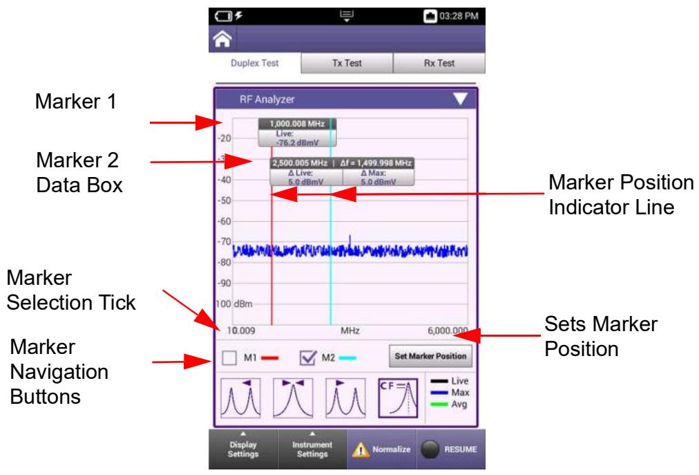
Figure 5-7 RF Analyzer Marker Controls
Table 5-20 RF Analyzer Marker Controls and Settings
| Control/Setting | Description |
| Marker Selection Tick Boxes | The M1 and M2 tick boxes are used to select a marker. The tick box that is selected specifies the marker to which any settings or configuration changes are applied. |
| Set Marker Position Button | Pressing the Set Marker Position button displays a window that is used to define a specific frequency at which to place the selected marker. |
| Marker Indicator Line | Markers are attached to a vertical line which provides a visual indicator of the marker's position on the plot field. The Marker Indicator Line is locked to the marker, and moves whenever the marker is repositioned on the plot field. The Marker Indicator Line can also be used to move the marker on the plot field. See section 5.2.9.7, “Setting Marker Position”, on page 5-41. |
| Marker Navigation Buttons | Pressing one of the Marker Navigation buttons moves the selected marker as described below. |
| Marker Left to Peak When pressed, the selected marker is moved left to the next peak on the signal. | |
| Marker to Peak When pressed, the selected marker is moved to the highest peak on the signal. | |
| Marker Right to Peak When pressed, the selected marker is moved right to the next peak on the signal. | |
| Marker Set CF When pressed, the signal's center frequency is set to the selected marker's position. |
5.2.9.6 Marker Data Fields
Markers are displayed when the RF Analyzer is opened, but data is not displayed until the trace is enabled. Marker 1 and Marker 2 Data Boxes display the following information:
Marker Position
Marker
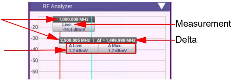
Figure 5-8 Identifying Marker Data Fields
Table 5-21 Marker Data Field Description
| Data Field | Description |
| Marker Position | Indicates the frequency at which the marker is positioned on the plot field. |
| Marker Reading | Indicates the power level of the signal at the marker position. |
| Delta Position | Indicates the difference between Marker 1 and Marker 2 position. |
| Measurement Type | Marker 1 only displays Live trace data; Marker 2 displays Live trace data, as well as Max and Min trace data when these measurement types traces are enabled. |
5.2.9.7 Setting Marker Position
Marker position can be defined using one of the following methods:
Using the Set Marker Position Button
- Select the marker tick box for the marker that you want to move.
- Press the Set Marker Position button.
- When the parameter field is displayed, enter the frequency where the marker is to be placed on the plot field.
- Select the OK button to apply the change.
Drag and Drop Marker to Position
- Select the marker tick box for the marker that you want to move.
- Press and hold the Marker Indicator Line for the marker.
- When the Marker Indicator Line appears fuzzy as shown in Figure 5-9, drag the line to the desired position on the plot field.
- Release the Indicator Line when the marker is at the desired position.
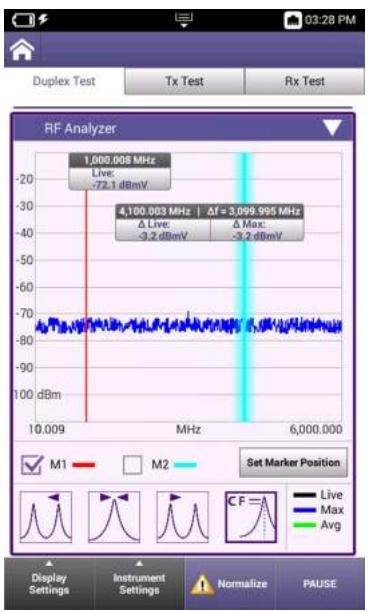
Figure 5-9 Marker Indicator Line - Drag and Drop
Using the Marker Reading Window
- Select the marker tick box for the marker that you want to move.
- Press and hold the marker's Marker Data Box.
- When parameter field is displayed, enter the frequency where the marker is to be placed on the plot field.
- Select the OK button to apply the change.
Marker Navigation Buttons
- Select the marker tick box for the marker that you want to move.
- Press the desired Marker Navigation button. See section, "Marker Navigation Buttons", on page 5-40 for information about marker navigation buttons.
5.2.10 AF Analyzer
The AF Analyzer provides users with the ability to examine a signal in either the time domain or frequency domain.
The Time Domain plot represents how the signal changes over time; the Frequency Domain plot represents the signal within each frequency band over a given frequency span. The AF Analyzer is used to evaluate a variety of aspects of audio signals such as level, frequency response, noise and distortion.
5.2.10.1 AF Analyzer Frequency Domain Tab
The AF Analyzer Frequency Domain tab consists of the following areas or groups of controls and settings:
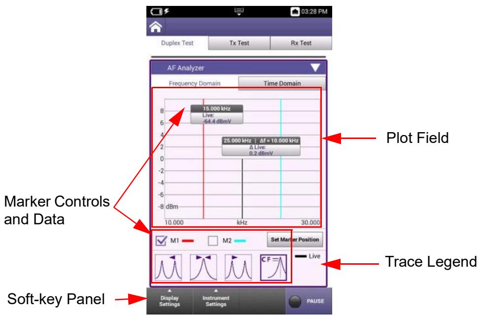
Figure 5-10 AF Analyzer Frequency Domain Tab Layout
Plot Field
The plot field displays a visual representation of the received signal. Controls and settings are available that allow the user to adjust settings such as plot scale, modes of operation and the types of traces being displayed on the plot.
See section 5.2.10.1.2, "AF Analyzer Frequency Domain Instrument Settings", on page 5-45 for a description of the controls and settings that are supported on the AF Analyzer.
Marker Controls and Data Fields
The AF Analyzer contains a variety of marker functions, controls and settings that allow the user to create custom test scenarios. AF Analyzer markers operate in the same manner as the RF Analyzer markers. See section 5.2.9.5, "RF Analyzer Marker Controls", on page 5-39 for information about marker controls, navigation and configuration.
Trace Legend
The trace legend indicates the trace types that are currently active, and the color of the line used to represent each trace type. The types of traces that are displayed on the plot field are selected using the Active Trace button located in the Displays Settings menu.
Soft-key Panel
The soft-key panel contains controls and settings that are used to configure the AF Analyzer. soft-keys are described below in section 5.2.10.1.1.
5.2.10.1.1 AF Analyzer Frequency Domain Soft-key Panel
The AF Analyzer Frequency Domain soft-key panel contains the following controls:
Table 5-22 AF Analyzer Frequency Domain Softkeys
| Soft-key | Description |
| Display Settings | The AF Analyzer Frequency Domain Plot uses the same display settings found in the AF Analyzer. See section 5.2.9.3, on page 5-34 for a description of these settings. |
| Soft-key | |
| Instrument Settings Soft-key | The Instrument Settings menu accesses the controls and settings that define how the AF Analyzer receives and processes an incoming signal. See section 5.2.10.1.2, on page 5-45 for a description of these settings. |
| Pause/Resume Soft-key | Pressing the Pause soft-key temporarily halts data updates to the UI. When this occurs, the soft-key updates to the Resume soft-key. Pressing the Resume soft-key restarts measurements. |
5.2.10.1.2 AF Analyzer Frequency Domain Instrument Settings
The Frequency Domain Instrument Settings menu accesses the controls and settings that define how the AF Analyzer receives and processes an incoming signal.
Table 5-23 Frequency Domain Instrument Settings
| Control/Setting | Description |
| Port | The AF Analyzer Port menu selects which input port is being used to receive the incoming signal.Audio InAudio In should be selected to analyze an incoming audio signal.DemodDemod should be selected to analyze the demodulated portion of an incoming RF signal |
| Coupling | The Coupling menu accesses settings that define the Resolution Bandwidth (RBW) and acquisition time that the Analyzer uses to filter the signal.Resolution Bandwidth (RBW)RBW filters are the bandpass filters in the IF path that determine the RF Noise floor and how close two signals can be and still be viewed separately on the analyzer.A narrower RBW setting more clearly displays close signals as separate signals, however, a narrower bandwidth setting results in a longer sweep time.An RBW setting that is too wide causes signals that are closed together to appear as one signal.Auto: When Auto is selected, the system sets RBW to a filter appropriate to the characteristics identified in the received signalManual: When Manual is selected, the user can manually define the RBW. |
| Reference Level | The Reference Level field sets the top value on the display graph. The Reference Level can be set to any value within the specified range. The Reference Level of the display must be set so that the RF signal level falls within the display area. |
| Frequency Mode | Frequency Mode selects the method used to define the span of the analyzer plot field. Parameters update according to the type of mode selected.Full Span Frequency ModeWhen Full Span is selected, the span defaults to the instrument's full frequency range. The UI updates to display the start and stop frequencies as read-only data fields. |
| Frequency Mode (cont) | |
| Center/Span Frequency Mode | |
| Center/Span Frequency mode of operation specifies the center frequency value as well as the frequency span setting. | |
| When Center/Span is selected, the UI displays a Center Frequency and Span setting. Center/Span Mode uses the sweep Center Frequency value and span setting to define the frequency span. | |
| The maximum span of the display is 5 MHz, which is equal to the channel width of the instrument's receiver. | |
| Start/Stop Frequency Mode | |
| Start-Stop Frequency mode of operation defines the sweep start and sweep end frequencies of the swept measurement range. | |
| When Start/Stop is selected, the UI displays Start Frequency and Stop Frequency fields. The sweep start and sweep stop frequencies define the frequency span. | |
| Amplitude | Amplitude settings affect how the plot field's vertical scaling and how the signal appears when displayed on the plot field. |
| Scale | |
| The AF Analyzer uses logarithmic scaling to display the signal amplitude on the analyzer vertical axis. Differences in signal amplitudes are compressed because low amplitude signals are amplified and high amplitude are compressed. This allows signal with widely varying amplitudes to be displayed on the same plot. Log scale is used to view both low amplitude and high amplitude frequencies with same clarity. | |
| Vertical Scale | |
| Selects the dB division between the vertical scaling on the plot field. | |
| Detector Type | The AF Analyzer uses detectors to accurately map the correct signal power to the correct frequency point on the display. Future development will support selectable detector types. |
5.2.10.1.3 AF Analyzer Frequency Domain Markers
AF Analyzer Frequency Domain markers operate in the same manner as the RF Analyzer markers. See section 5.2.9.5, "RF Analyzer Marker Controls", on page 5-39 for information about marker controls, navigation and configuration.
5.2.10.2 AF Analyzer Time Domain Tab
The AF Analyzer Time Domain tab contains a plot field and soft-key panel.
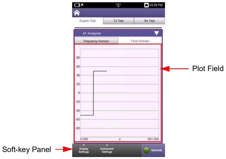
Figure 5-11 AF Analyzer Time Domain Tab Layout
Plot Field
The plot field displays a visual representation of the received signal. Controls and settings are available that allow the user to adjust settings such as plot scale, modes of operation and the types of traces being displayed on the plot.
See section 5.2.10.2.2, on page 5-48 for a description of the controls and settings that are supported on the AF Analyzer.
Soft-key Panel
The soft-key panel contains controls and settings that are used to configure the AF Analyzer. See section 5.2.10.1.1, on page 5-44 for a description of the AF Analyzer softkeys.
5.2.10.2.1 AF Analyzer Time Domain Soft-key Panel
The AF Analyzer Time Domain soft-key panel contains the following controls:
Table 5-24 AF Analyzer Time Domain Softkeys
| Soft-key | Description |
| Display Settings | The AF Analyzer Time Domain Plot uses the same display settings found in the RF Analyzer. See section 5.2.9.3, “RF Analyzer Display Settings”, on page 5-34 for a description of these settings. |
| Soft-key | |
| Instrument Settings Soft-key | The Instrument Settings menu accesses the controls and settings that define how the AF Analyzer receives and processes an incoming signal. See section 5.2.10.2.2, “AF Analyzer Time Domain Instrument Settings”, on page 5-48 for a description of these settings. |
| Pause/Resume Soft-key | Pressing the Pause soft-key temporarily halts data updates to the UI. When this occurs the soft-key updates to the Resume soft-key. Pressing the Resume soft-key restarts measurements. |
5.2.10.2.2 AF Analyzer Time Domain Instrument Settings
The Time Domain Instrument Settings menu accesses the controls and settings that define how the AF Analyzer receives and processes an incoming signal.
Table 5-25 AF Analyzer Time Domain Instrument Settings
| Control/Setting | Description |
| Port | The AF Analyzer Port menu selects which input port is being used to receive the incoming signal.Audio InAudio In should be selected to analyze an incoming audio signal. Audio Filters are selected on the RF Receiver panel (see “AF Filters” on page 5-12).DemodDemod should be selected to analyze an incoming demodulated RF audio signal. |
| Coupling | The Coupling menu accesses settings that define the Resolution Bandwidth (RBW) and acquisition time that the Analyzer uses to filter the signal. AC Coupling AC coupling filters the DC signal component out of a signal that contains both AC and DC components. The DC component of a signal acts as a voltage offset so removing the component may increase the resolution of signal measurements. DC Coupling DC coupling does not filter components from the signal; both AC and DC signal components are therefore present in the signal. DC coupling is typically used when any offset voltage present is <±100 mV or if the DC content of the signal is important. |
| Reference Level | The Reference Level field defines the top power level line on the plot field's vertical scale. Power levels can be measured at any point on the trace in conjunction with the Horizontal Time/div setting. |
| Horizontal | The horizontal setting defines the scale and position of the time axis of the display. Unit Unit selects whether the horizontal scale is represented in seconds (s), milliseconds (ms) or microseconds (μs). Time/Div The horizontal scale selects the amount of time represented by each division (Time/Div) on the plot's horizontal axis. |
| Vertical | The vertical scale selects the number of units of measurements per division on the plot's vertical axis. When Audio In is selected as the input port, the unit of measurement is Volts or milliVolts. When Demod is selected as the input port, the units will be as follows based on the RF Received Demodulation Type: • FM or Digital: Hz • AM: % (percent) |
5.3 Spectrum Analyzer
5.3.1 Introduction
The Spectrum Analyzer measures various performance characteristics of an applied (incoming) signal across the full frequency range of the CX100. The Spectrum Analyzer can be used to evaluate performance parameters such as power, harmonics, sidebands and phase noise of a DUT.
The Spectrum Analyzer is typically used to measure parameters of known signals, as well as locate the power and frequency of unknown signals.
5.3.2 Spectrum Analyzer Screen Layout
The Spectrum Analyzer screen consists of the following areas or groups of controls and settings:
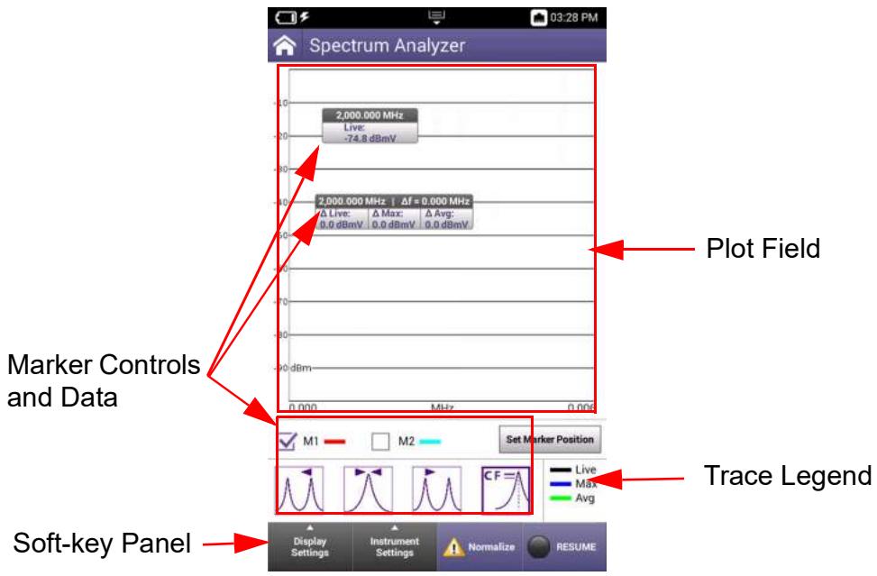
Figure 5-12 Spectrum Analyzer Screen Layout
Plot Field
The plot field displays a visual representation of the received signal. Controls and settings are available that allow the user to adjust settings such as plot scale, modes of operation and the types of traces being displayed on the plot.
See section 5.3.2.3, on page 5-52 and section 5.3.2.4, on page 5-54 for a description of the controls and settings that are supported on the Spectrum Analyzer.
Marker Controls and Data Fields
The Spectrum Analyzer contains a variety of marker functions, controls and settings that allow the user to create custom test scenarios. Spectrum Analyzer markers operate in the same manner as the RF Analyzer markers. See section 5.2.9.5, "RF Analyzer Marker Controls", on page 5-39 for information about marker controls, navigation and configuration.
Trace Legend
The trace legend indicates the trace types that are currently active, and the color of the line used to represent each trace type. The types of traces that are displayed on the plot field are selected using the Active Trace button located in the Display Settings menu.
Soft-key Panel
The soft-key panel contains controls and settings that are used to configure the RF Analyzer. See section 5.3.2.2, on page 5-51 for a description of RF Analyzer softkeys.
5.3.2.1 Spectrum Analyzer Markers
Spectrum Analyzer markers operate in the same manner as the RF Analyzer markers. See section See section 5.2.9.5, "RF Analyzer Marker Controls", on page 5-39 for information about marker controls, navigation and configuration.
5.3.2.2 Spectrum Analyzer Soft-key Panel
The Spectrum Analyzer soft-key panel contains the following controls:
Table 5-26 Spectrum Analyzer Softkeys
| Soft-key | Description |
| Display Settings Soft-key | The Display Settings soft-key opens a menu that contains controls and settings that affect display layout and manages how traces are displayed on plot fields. See section 5.3.2.3, “Spectrum Analyzer Display Settings”, on page 5-52 for a description of these settings. |
| Instrument Settings Soft-key | The Instrument Settings menu accesses the controls and settings that define how the Spectrum Analyzer receives and processes an incoming signal. See section 5.3.2.4, “Spectrum Analyzer Instrument Settings”, on page 5-54 for a description of these settings. |
| Normalize Soft-key | TheNormalize soft-key opens a settings window that contains controls and settings which are used to zero out the Spectrum Analyzer signal path, removing any residual power from the RF path which eliminates the system's frequency response error. Spot FrequencyThe Spot Frequency field defines the frequency to be zeroed out. Pressing the Run Normalize soft-key initiates the process. |
| Normalize | An attention indicator is displayed on theNormalize soft-key when the system detects residual power on the signal path. When this condition occurs, Normalize should be performed to ensure accurate measurements. |
| Pause/Resume Soft-key | When the Spectrum Analyzer is displayed on the UI, the signal trace is active by default.Pressing the Pause soft-key stops data updates to the UI and the soft-key updates to the Resume soft-key.Pressing the Resume soft-key displays live trace data. |
5.3.2.3 Spectrum Analyzer Display Settings
The Display Settings soft-key opens a menu that contains controls and settings that affect display layout and manages how traces are displayed on plot fields.
Table 5-27 Spectrum Analyzer Display Settings
| Control/Setting | Description |
| Rotate Screen | The Rotate Screen soft-key switches the UI between Portrait or Landscape orientation. Changes orientation of plot field on the device (updates remote session when using VNC application to view the UI). Orientation is not stored as part of Save Trace settings. |
| Active Trace Button | The Active Trace button opens a window that selects the type of trace(s) to be displayed on the plot field. Multiple traces can be selected at any given time on each plot. • Max: displays highest amplitude received • Min: displays lowest amplitude received • Live: displays live signal trace • Average: displays an averaged signal trace; average is defined by value defined in the Average field. The UI contains a trace legend which shows the trace types that are currently being displayed on the plot field and the color used to represent the signal on the plot field. |
| Average (Field) | The Average field is enabled when Average is selected as the active trace. The Average field defines the number of traces to be used to calculate an average signal trace. |
| Capture Trace Button | When the Capture Trace button is pressed, a trace is “held” on the display. When more than one trace is active on a plot, only one of the active traces will be captured. When multiple trace types are enabled, traces are captured in the following priority: • MAX Priority 1 • MIN Priority 2 • Average Priority 3 • Live Priority 4 For example, if Average and Live traces are enabled, the Average trace is captured. If Max and Average traces are enabled, the Max trace is captured. When the Capture Trace button is pressed, the Clear Trace button is enabled which is used to remove a captured trace from the plot field. |
| Clear Trace Button | The Clear Trace button is active when a the Captured Trace button has been pressed and a trace is captured on the plot field. Pressing the Clear Trace button removes the captured trace from the plot field. |
| Save Trace Button | The Save Trace button displays a window that is used to enter a name for saving a file. The file will be saved to the location defined in System Settings. See section 4.2.7, “Specifying File Save Location”, on page 4-8. The Save Trace function saves x,y data in .csv file format. |
| Recall Trace Button | The Recall Trace button displays a file selection box which allows user to recall a stored trace. The stored trace file can be recalled from the device or from a USB device. |
5.3.2.4 Spectrum Analyzer Instrument Settings
The Instrument Settings menu accesses the controls and settings that define how the Spectrum Analyzer receives and processes an incoming signal.
Table 5-28 Spectrum Analyzer Instrument Settings
| Control/Setting1 | Description |
| Port | The Spectrum Analyzer Port menu selects the input connector for analyzing incoming signals.ANT/SWRANT/SWR should be selected to perform over the air testing using an external antenna or when test parameters require maximum input sensitivity. The ANT/SWR connector should be used when analyzing low level RF signals.DUPLEXANT/SWR should be used when analyzing high power RF signals. The DIPLEX connector is a combined (Duplexed) connector that provides an RF Gen output connection and an RF Receiver input connection. |
| Coupling | Resolution Bandwidth (RBW)RBW filters are the bandpass filters in the IF path that determine the RF Noise floor and how close two signals can be and still be viewed separately on the analyzer.A narrower RBW setting more clearly displays close signals as separate signals; a narrower bandwidth setting results in a longer sweep time.An RBW setting that is too wide causes signals that are close together to appear as one signal.Auto: system sets RBW to a filter appropriate to the characteristics identified in the received signalManual: allows the user to manually define the RBW. |
| Video Bandwidth (VBW)The Analyzer includes a low pass filter, called the video filter, in the signal path following the detector. The video filter reduces high frequency noise on the detected signal and allows low level signals to be identified which would otherwise be buried in the noise.The bandwidth of the video filter is called the video bandwidth, or VBW. The VBW defines the high frequency cutoff point of the filter. Any frequencies that are above the VBW value are clipped.VBW helps improve resolution of weak signals in the presence of the noise signal. The narrower the VBW, the less noise there is in the output signal; however, the narrower the bandwidth, the longer the sweep time. | |
| Reference Level | The Reference Level field defines the top value on the plot field's vertical scale. Reference Level can be set to any value within the specified range, but should be set to a value above the expected power level of the incoming signal in order to view the full signal waveform. |
| Frequency Mode | Frequency Mode selects the method used to define the span of the analyzer plot field. Parameters update according to the type of mode selected.Full Span Frequency modeWhen Full Span is selected, the span defaults to the instrument's full frequency range. The UI updates to display the Start and Stop frequencies as read-only data fields. |
| Center/Span Frequency ModeCenter/Span Frequency mode of operation specifies the center frequency value as well as the frequency span setting.When Center/Span is selected, the UI displays a Center Frequency and Span setting. Center/Span Mode uses the sweep Center Frequency value and span setting to define the frequency span. | |
| Control/Setting' | Description |
| Frequency Mode (cont) | |
| Start/Stop Frequency Mode | |
| Start-Stop Frequency mode of operation defines the sweep start and sweep end frequencies of the swept measurement range. | |
| When Start/Stop is selected, the UI displays a Start Frequency and Stop Frequency fields. The start and stop frequencies define the frequency span. | |
| Zero Span Frequency Mode | |
| In Zero Span Mode the Channel Analyzer does not perform a frequency sweep: it detects the power level at the set frequency. The trace shows detected power against time. When operating in Zero-Span Mode, marker position is specified in time. | |
| Amplitude Settings | Amplitude settings affect how the plot field's vertical scaling and how the signal appears when displayed on the plot field. |
| Scale | |
| The Spectrum Analyzer uses logarithmic scaling to display the signal amplitude on the analyzer vertical axis. Differences in signal amplitudes are compressed because low amplitude signals are amplified and high amplitude are compressed. This allows signal with widely varying amplitudes to be displayed on the same plot. Log scale is used to view both low amplitude and high amplitude frequencies with same clarity. | |
| Vertical Scale | |
| Selects the dB division between the vertical scaling on the plot field. | |
| Detector Type | The Spectrum Analyzer uses detectors in order to accurately map the correct signal power to the correct frequency point on the display. The Detector Type selects the type of math that is used to identify specific information in a received signal. The CX100 Spectrum Analyzer provides the following detector selections: |
| Peak | |
| When Peak is selected, the Spectrum Analyzer displays the maximum value of data sampled within the corresponding time interval for each trace point. Peak would typically be used to measure the peak power of a signal. | |
| Control/Settingi | Description |
| Detector Type (cont) | |
| Negative Peak | |
| When Negative Peak is selected, the Spectrum Analyzer displays the minimum value of data sampled within the corresponding time interval for each trace point. Negative Peak could be used to help identify CW and pulsed signals by comparing positive and negative peak values. | |
| Normal | |
| For the Normal detector, if a continuously rising or falling value is detected, the most positive value is returned, otherwise the bucket processor alternates between most positive and most negative peak. | |
| Sample | |
| When Sample is selected, the Spectrum Analyzer displays the power level corresponding to the data point of the corresponding time interval. A sample detector provides a sample for each trace point on the plot field; each trace point represents a single sample evenly spaced across the Span of the frequency domain. | |
| A sample detector is effective for measuring noise-like signals or low power continuous wave (CW) signals that are near the Analyzer's noise floor. | |
| Δ | A sample detector can show an inaccurate reading for the amplitude of a CW signal if the RBW is set too narrow (reading will be too low). |
| RMS | |
| When RMS is selected, the Spectrum Analyzer displays the average power measurement calculated over the specified number of trace points. | |
| RMS detector would typically be used when performing EMI testing. | |
| Δ | NOTE |
| The number of trace points is defined by the Number Points field in the Sweep controls and settings (see below). | |
| Control/Setting1 | Description |
| Sweep | Sweep time defines how quickly trace data is acquired and updated to the display. This setting must be fast enough to provide quick measurement results, but slow enough to allow the power values at each point to be measured. |
| Number Points | |
| This field defines the number of data points that the Spectrum Analyzer gathers during a single measurement sweep. A higher setting results in more accurate measurement; however, a higher number of data points may result in longer acquisition time. | |
| Sweep Type | |
| When set to Auto, the instrument optimizes the Sweep Time based on the characteristics of the incoming signal. | |
| When set to Manual, a sweep time setting can be entered using the Sweep Time field. | |
| Sweep Time | |
| This field is enabled when Sweep Type is set to Manual. The setting allows the user to manually define the sweep time setting. | |
| When Sweep Type is set to Auto; the field displays the system defined sweep time setting. | |
| Sweep Mode | |
| This toggle switch selects whether the analyzer performs signal sweeps continuously, or if the analyzer performs a single sweep before being switched off. | |
| In Single sweep mode, the measurement is stopped after a single signal sweep. | |
| In Continuous mode, the analyzer measures continuously, repeating the signal sweep as long as the analyzer is ON. | |
5.4 VSWR/DTF
5.4.1 Introduction
The VSWR/DTF test function supports Voltage Standing Wave Ratio (VSWR), Return Loss and Distance to Fault (DTF) measurements, providing the tools necessary to analyze, troubleshoot and characterize cable and antenna systems.
A cable database is provided for DTF testing. The cable database contains a list of standardized cables for quick test setup and also allows the user to add cables for customer test requirements.
5.4.2 VSWR/DTF Screen Layout and Behavior
The VSWR/DTF screen uses a tabbed layout which allows for quick selection between available functions. Test function screens are displayed by selecting the tab at the top of the screen, or by swiping the screen left or right. Screen layout contents are described under each test function.
5.4.3 VSWR Test Function
The VSWR test function provides users with the ability to select VSWR or Return Loss modes for calculating reflection (see "Measurement Mode" on page 5-63).
VSWR
Voltage Standing Wave Ratio (VSWR) is a measurement that represents how well an antenna's impedance is matched to the radio or transmission line to which it is connected.
The smaller the VSWR measurement, the better the antenna and transmission line match, and therefore less loss and better signal strength on the transmission line. The minimum VSWR is 1.0, which means no power is being reflected.
Return Loss
Return loss (RL) is the ratio of the reflected signal to the transmitted signal. A low return loss indicates less signal reflection and better signal strength. A high return loss indicates more signal reflection and less signal strength, indicating an issue along the transmission line.
When Return Loss is selected measurements are displayed in dB.
5.4.3.1 VSWR Screen Layout
The VSWR screen consists of the following areas or groups of controls and settings:
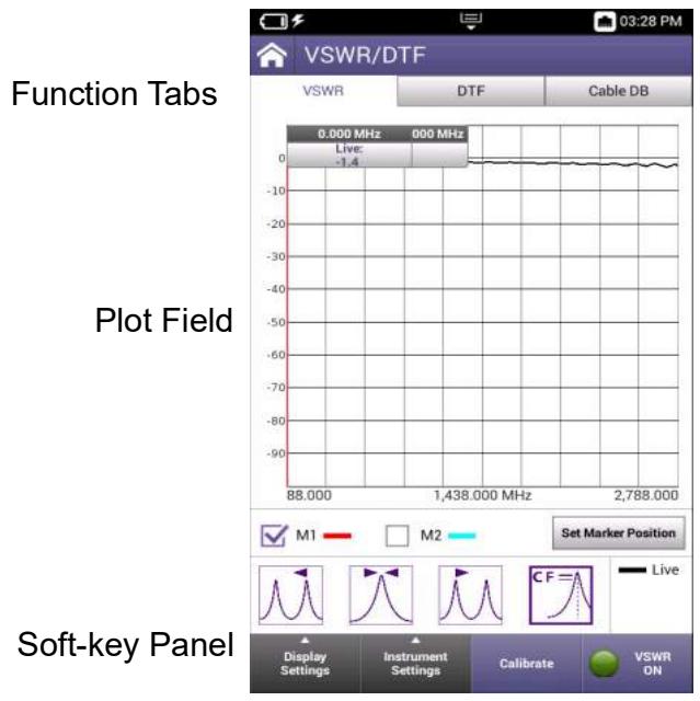
Figure 5-13 VSWR Screen Components
Function Tabs
The tabs at the top of the screen select the measurement mode or access the cable database controls and settings.
Plot Field
The plot field displays a visual representation of the received signal. Controls and settings are available that allow the user to adjust settings such as plot scale and modes of operation.
See section 5.4.3.3, on page 5-62 and section 5.4.3.4, on page 5-63 for a description of the controls and settings that are supported for VSWR tests.
Soft-key Panel
The soft-key panel contains controls and settings that are used to configure VSWR measurements. See section 5.4.3.2, on page 5-61 for a description of VSWR softkeys.
5.4.3.2 VSWR Soft-key Panel
The VSWR soft-key panel contains the following controls:
Table 5-29 VSWR Softkeys
| Soft-key | Description |
| Display Settings Soft-key | The Display Settings soft-key opens a menu that contains controls and settings that affect display layout and manages how traces are displayed on plot fields. See section 5.4.3.3, “VSWR Display Settings”, on page 5-62 for a description of these settings. |
| Instrument Settings Soft-key | The Instrument Settings menu accesses the controls and settings that define how VSWR measurements are performed. See section 5.4.3.4, “VSWR Instrument Settings”, on page 5-63 for a description of these settings. |
| Calibrate Soft-key | Pressing the Calibrate soft-key opens a window that contains radio buttons that select the following: Internal Calibration The internal calibration procedure is an automated procedure that utilizes the devices internal Short/Open/Load (SOL). External Calibration The external calibration procedure requires use of external equipment and connections. External procedure is a manual procedure that requires the user to configure hardware connections at various stages in the procedure. On-screen instructions are provided at various stages of the calibration procedure which guide the user through the procedure. |
| ! Calibrate | An attention symbol is displayed on the Calibrate soft-key when calibration needs to be performed. When this condition occurs, calibration should be performed to ensure accurate measurements. |
| Pause/Resume Soft-key | Pressing the Pause soft-key temporarily halts data updates to the UI. When this occurs the soft-key updates to the Resume soft-key. Pressing the Resume soft-key restarts the VSWR measurement. |
5.4.3.3 VSWR Display Settings
The Display Settings soft-key opens a menu that contains controls and settings that affect display layout and manages how traces are displayed on plot fields.
Table 5-30 VSWR Display Settings
| Control/Setting | Description |
| Rotate Screen | The Rotate Screen soft-key switches the UI between Portrait or Landscape orientation. Changes orientation of plot field on the device (updates remote session when using VNC application to view the UI). Orientation is not stored as part of Save Trace settings. |
| Active Trace Button | The Active Trace button opens a window that selects the type of trace(s) to be displayed on the plot field. Multiple traces can be selected at any given time on each plot. • Max: displays highest signal received • Min: displays lowest signal received • Live: displays live signal trace • Average: displays an averaged signal trace; average is defined by the value in the Average field. |
| Average (Field) | The Average field is enabled when Average is selected as the active trace. The Average field defines the number of traces to be used to calculate an average signal trace. |
| Capture Trace Button | When the Capture Trace button is pressed, a trace is “held” on the display. When more than one trace is active on a plot, only one of the active traces will be captured. When multiple trace types are enabled, traces are captured in the following priority: • MAX Priority 1 • MIN Priority 2 • Average Priority 3 • Live Priority 4 For example, if Average and Live traces are enabled, the Average Trace is captured. If Max and Average traces are enabled, the Max trace is captured. When the Capture Trace button is pressed, the Clear Trace button is enabled which is used to remove a captured trace from the plot field. |
| Clear Trace Button | The Clear Trace button is active when a the Captured Trace button has been pressed and a trace is captured on the plot field. Pressing the Clear Trace button removes the captured trace from the plot field. |
| Save Trace Button | The Save Trace button displays a window that is used to enter a name for saving a file. The file will be saved to the location defined in System Settings. See section 4.2.7, “Specifying File Save Location”, on page 4-8. |
| The Save Trace function saves x,y data in .csv file format. | |
| Recall Trace Button | The Recall Trace button displays a file selection box which allows user to recall a stored trace. The stored trace file can be recalled from the device or from a USB device. |
5.4.3.4 VSWR Instrument Settings
The Instrument Settings menu accesses the controls and settings that define how VSWR measurements are performed.
Table 5-31 VSWR Instrument Settings
| Control/Setting | Description |
| Measurement Mode | Measurement Mode allows the user to perform either VSWR or Return Loss (RL) measurements. |
| Frequency | The start and stop frequencies define the span of the plot field. Parameters update according to the type of mode selected. Start Frequency Defines the lower end of the measurement range. Stop Frequency Defines the upper end of the measurement range. |
| Number of Points | Defines the number of data points acquired to perform the measurement. |
| Vertical Scale | The Vertical Scale button opens a settings window that allows the user to manually define the vertical scale of the plot field or to use autoscale to allow the system to define the vertical scale according to detected signal characteristics. Autoscale Autoscale sets the top and bottom scale to values appropriate for the detected signal characteristics. Top of Scale Top of Scale manually defines the upper value of the plot fields vertical scale. |
| Bottom of Scale This field is used to manually defines the lower value of the plot fields vertical scale. |
5.4.4 DTF Test Function
Distance to Fault (DTF) is an analysis that is used to identify signal path degradation in cables and transmission lines that may be a result of conditions such as poor connections, damaged cables, or faulty antennas.
5.4.4.1 DTF Tab Layout
The DTF Tab consists of the following areas or groups of controls and settings:
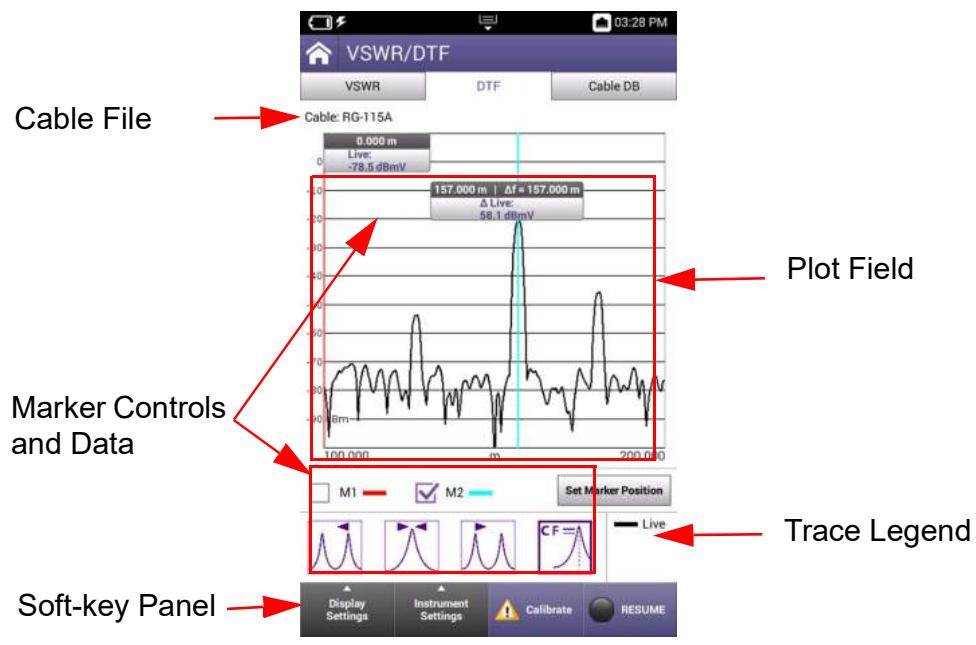
Figure 5-14 DTF Tab Layout
Cable File Field
The field located above the plot identifies the cable file being used for performing the DTF test. This is a read only field that displays the name of the cable file that is selected on the Cable DB tab (see section 5.4.5, on page 5-68).
Plot Field
The plot field displays a visual representation of the measurement. Controls and settings are available that allow the user to adjust settings such as plot scale and the types of traces being displayed on the plot.
See section 5.4.3.3, on page 5-62 and section 5.4.3.4, on page 5-63 for a description of the controls and settings that are supported for DTF measurements.
Marker Controls and Data Fields
The plot field supports a variety of marker functions, controls and settings that allow the user to create custom test scenarios. DTF markers operate in the same manner as the RF Analyzer markers. See section 5.2.9.5, "RF Analyzer Marker Controls", on page 5-39 for information about marker controls, navigation and configuration.
Trace Legend
The trace legend indicates the trace types that are currently active, and the color of the line used to represent each trace type. The types of traces that are displayed on the plot field are selected using the Active Trace button located in the Display Settings Menu.
Soft-key Panel
The soft-key panel contains controls and settings that are used to configure DTF Measurements. See section 5.4.4.2, on page 5-65 for a description of softkeys that are supported for DTF measurements.
5.4.4.2 DTF Soft-key Panel
The DTF soft-key panel contains the following controls:
Table 5-32 DTF Softkeys
| Soft-keys | Description |
| Display Settings Soft-key | The Display Settings soft-key opens a menu that contains controls and settings that affect display layout and manages how traces are displayed on plot fields. DTF test function uses the same display settings that are supported in VSWR test. See section 5.4.3.3, “VSWR Display Settings”, on page 5-62 for information about Display Settings. |
| Instrument Settings Soft-key | The Instrument Settings menu accesses the controls and settings that define how DTF measurements are performed. See section 5.4.4.3, “DTF Instrument Settings”, on page 5-66 for a description of these settings. |
| Calibrate Soft-key | Calibration should be performed to ensure the accuracy of DTF measurements. |
| An attention symbol is displayed on the Calibrate soft-key when the specified frequency values are outside of the calibrated frequency range and therefore a calibration needs to be performed. Pressing the Calibrate soft-key opens a window that contains radio buttons that select the following: Internal Calibration The internal calibration procedure is an automated procedure that utilizes the devices internal Short/Open/Load (SOL). External Calibration The external calibration procedure requires use of external equipment and connections. External procedure is a manual procedure that requires the user to configure hardware connections at various stages in the procedure. On-screen instructions are provided at various stages of the calibration procedure which guide the user through the procedure. | |
| Pause/Resume Soft-key | Pressing the Pause soft-key temporarily halts data updates to the UI. When this occurs the soft-key updates to the Resume soft-key. Pressing the Resume soft-key restarts the VSWR measurement. |
5.4.4.3 DTF Instrument Settings
The Instrument Settings menu accesses the controls and settings that define how distance to fault measurements are performed.
Table 5-33 DTF Instrument Settings
| Control/Setting | Description |
| Horizontal Range | The horizontal range allows the user to specify the distance unit to use in the measurement. The selection is displayed on horizontal axis. |
| Distance Settings | Distance settings define the parameters used to evaluate the transmission line. Start The Start field defines the beginning point along the length of the cable which is the lower value of the measurement range. |
| Distance Settings (cont) | |
| Stop | |
| The Stop field defines the end point along the length of the cable which is the upper value of the measurement range. | |
| Step | |
| This Step field specifies the number of points for the measurement. | |
| IF Bandwidth | |
| This menu selects the IF bandwidth used for collecting raw data. | |
| Auto Alias Free Range | |
| Alias free distance span is used to prevent aliasing (false signals) that can occur when a fault is outside of the desired span. A larger alias free span makes it less likely for a false signal to occur, but may make the measurement take longer. | |
| When Auto Alias Free Range is selected (auto mode), the Stop Setting is multiplied by 2 to calculate the free distance span. | |
| When Auto Alias Free Range is not selected (manual mode), DTF measurements use the value in the Alias Free Span field. | |
| Alias Free Span | |
| This field is enabled when Auto Alias Free Range is not selected (manual mode). This field defines the Alias Free Span setting when Auto Alias Free Range is off. | |
| Vertical Scale | The Vertical Scale button opens a settings window that allows the user to manually define the vertical scale of the plot field or to use autoscale to allow the system to define the vertical scale according to detected signal characteristics. |
| Autoscale | |
| Autoscale sets the top and bottom scale to values appropriate for the detected signal characteristics. | |
| Top of Scale | |
| Top of Scale manually defines the upper value of the plot fields vertical scale. | |
| Bottom of Scale This field is used to manually defines the lower value of the plot fields vertical scale. | |
5.4.5 Cable Database (DB)
The Cable Database (DB) contains pre-defined cable files that allow the user to quickly select a cable to be used for performing DTF measurements. Users can also create new cable files to meet specific test scenarios and requirements.
5.4.5.1 Cable DB Tab Layout
The Cable DB tab consists of the following main screen components:
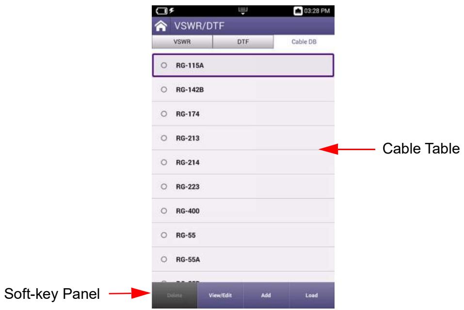
Figure 5-15 Cable DB tab Components
Cable Table
The cable table lists the cable configurations that are available for performing distance to fault (DTF) measurements. The table contains pre-defined cable setup files; controls and settings are provided to allow the user to configure custom cables.
Soft-key Panel
The soft-key panel contains controls that are used to manage and configure the cable database. See section 5.4.5.2, on page 5-69 for a description of the softkeys supported in the Cable Database.
5.4.5.2 Cable DB Soft-key Panel
The Cable Database soft-key panel contains the following soft-keys:
Table 5-34 Cable DB Softkeys
| Soft-key | Description |
| Delete Soft-key | Pressing this soft-key deletes the selected cable configuration file. A confirmation dialog box will be generated which requires the user to confirm the deletion. |
| View/Edit Soft-key | Pressing this soft-key opens a window that displays the characteristics of the selected cable configuration file. When a user-created cable file is opened, the user can edit information as desired. Pre-configured cable files cannot be edited. |
| Add Soft-key | Pressing this soft-key opens a window that allows the user to create a custom cable configuration file. |
| Load Soft-key | Pressing this soft-key loads the selected cable file. |
5.4.5.3 Cable DB Controls and Settings
The following controls and settings are used to manage the cables saved in the cable database:
Table 5-35 Cable DB Controls and Settings
| Control/Setting | Description |
| Cable Radio Buttons | The radio button located to the left of each cable name selects the cable for editing, loading, viewing or deletion. Only one cable can be selected at any given time. |
| Cable Name | This field indicates the name of the cable. When editing or adding a cable, the field accepts up to 50 alphanumeric characters. |
| Velocity | This field is the speed (velocity of propagation) at which an electrical signal is expected to travel through a cable (in comparison to the speed of light). Velocity of propagation is calculated as a percent (%); Velocity (factor) is displayed as a decimal value. |
| Loss | This field defines the power that a cable is expected to lose per every 100 feet traveled. |
5.4.5.4 Managing Cable Database
This section provides instructions for viewing, adding, deleting, and modifying the cables information stored in the cable database.

NOTE
See Appendix C "DTF Cable DB - Cable Values" for Pre-defined cable parameters. Pre-defined cables cannot be edited or deleted.
5.4.5.4.1 Viewing Cable Information
To View Cable Data
- Select the cable (radio button).
- Press the View/Edit soft-key.
- A window is displayed the shows cable data.
5.4.5.4.2 Editing Cable Information
To Edit a User-created Cable File
- Select the cable (radio button).
- Press the View/Edit soft-key.
- Make desired changes.
5.4.5.4.3 Creating New Cable
To Create a Cable File
- Press the Add soft-key.
- Enter a name in the data entry field.
- Enter the velocity of the cable that is to be tested.
- Enter the expected loss factor.
- Press the Save button to save the file.
5.4.5.4.4 Deleting a Cable
To Delete a User-created Cable File
- Select the cable (radio button).
- Press the Delete soft-key.
- At prompt, confirm deletion.
5.5 Autotest Function
The Autotest function supports radio specific automated test scripts. The Autotest function also provides the interface to load and run the CX100's Automated Self Test procedure.
5.5.1 Autotest Screen Layout
The Autotest screen consists of the following areas:
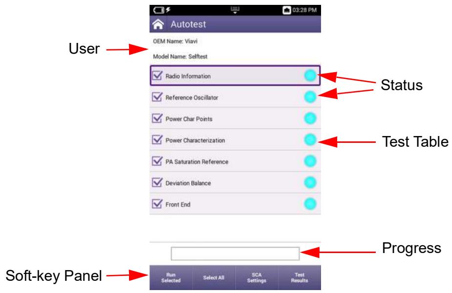
Figure 5-16 AutoTest Screen Layout and Functions
User Information
Fields which identify the user and test information.
Test Table
The test table lists the test script information and provides controls and indicators for test selection and test status.
Progress Bar
The progress bar provides a visual indicator of test progress.
Soft-key Panel
The soft-key panel contains controls that are used to perform different functions within AutoTest. See section 5.4.5.2, on page 5-69 for a description of the softkeys that are supported in Autotest.
5.5.2 Autotest Soft-key Panel
The Autotest soft-key panel contains the following soft-keys:
Table 5-36 Autotest Softkeys
| Soft-key | Description |
| Run Selected Soft-key | When the Run Selected Tests soft-key is pressed, the selected tests are performed. |
| Select All/ Unselect All | When the Select All soft-key is pressed, all tests in the table will be selected. When the Unselect All soft-key is pressed, all tests in the table will be unselected. |
| Pause Test Soft-key | When the Pause Test soft-key is pressed, the test sequence stops at the end of the test that is currently in progress. |
| Resume Soft-key | Pressing the Resume soft-key starts the test sequence from the point at which the test was paused. |
| Abort Soft-key | Pressing the Abort soft-key displays a user prompt which requires the user to confirm the request to stop the test. When the test is aborted, all data is lost and not retrievable. |
| Test Results Soft-key | When the Test Results soft-key is pressed, the screen updates to display a scrollable screen with test data. Test results cannot be viewed while a test is in progress; tests must be paused or completed before the soft-key is enabled. |
| Save Results Soft-key | When the Save Results soft-key is pressed, test results are automatically saved in XML format. Test results are also saved in formats that are selected using the Report Formats soft-key |
| Report Formats | Pressing the Report Formats soft-key displays a list of file formats that the user can select and save the test results as. The supported report formats are: PDF, HTML, JSON, and TXT. |
| Open Reports | Pressing the Open Reports soft-key displays a list of test results from previously run tests. The user can select a file to view. When a file is opened for viewing, other functions are available such as saving the file in a different file format or deleting the test result. |
| Delete Results Soft-key | Pressing Delete Results soft-key display a user prompt which requires user to confirm request to delete the results. Deleted results cannot be recovered. |
| SCA Settings Soft-key | The SCA Settings soft-key accesses controls and parameters that are used to configure the CX100 for operating in an SCA environment. See section 5.6.2, on page 5-75 for information. |
5.5.3 Autotest Controls and Settings
The following controls and settings are used to control Autotest operation and manage and review test results:
Table 5-37 Autotest Controls and Settings
| Control/Setting | Description |
| Tick Boxes | The tick boxes are used to select specific tests to be run; pressing the Select All soft-key enables all tick boxes. |
| Test Table | The test table lists separate test sequences which may be included in the loaded script/file. |
| Status Indicators | Indicator to the right of the test table color coded as follows to indicate individual test status: • Grey: when test is not selected to be included in the test run • Light blue: indicates test has been selected and has not yet been completed. • Green: indicates completed test has passed test criteria • Red: indicates completed test has failed test criteria |
5.5.4 Automated Self Test
The CX100 contains an automated built in test (BIT) called the Self Test. The Self Test procedure evaluates the general functionality of the test set's generate and receive functions, instruments, and switches, to ensure the device is operating properly.
See section 6.1, "CX100 Self Test Procedure", on page 6-2 for instructions to run the CX100 self test.

NOTE
Self Test does not verify that the device is operating to performance specifications.
5.5.4.1 Self Test Descriptions
5.5.4.1.1 RF Loop-back Test
The RF Loop-back test performs a series of RF Frequency Error and RF Power measurements at various frequencies to determine if the RF Generator and RF Receiver are functioning properly.
5.5.4.1.2 Analog Modulation/Demodulation Test
The Analog Modulation/Demodulation test uses the CX100 internal modulation generators and RF Receiver to determine if the modulation generators and demodulation meters are functioning properly.
5.5.4.1.3 Audio Loop-back Test
The Audio Loop-back test compares CX100 audio measurements with the CX100's AF Generator settings to determine if the AF Generators and audio meters are functioning properly.

NOTE
This test requires an external loop-back connection between the Audio Out and Audio In connector.
5.5.4.1.4 RF Analyzer Test
The RF Analyzer test uses the CX100 RF Generator and RF Receiver to evaluate the RF Analyzer's trace data to determine if the RF Analyzer is functioning properly.
5.5.4.1.5 Digital Modulation/Demodulation Test
The Digital Modulation/Demodulation test uses the CX100 RF Generator and Modulation Generator to play a sample .aiq waveform file of known parameters to determine if digital playback and digital meters are functioning properly.
5.5.4.1.6 Spectrum Analyzer Test
The Spectrum Analyzer test uses the CX100 RF Generator and RF Receiver to evaluate Spectrum Analyzer trace data to ensure the Spectrum Analyzer is functioning properly.
5.5.4.1.7 VSWR/DTF Test
5.6 SCA Capability
The CX100 hosts a Software Communication Architecture (SCA) Core Framework that implements the latest SCA version 4.1 full profile and supports backwards compatibility profile for SCA version 2.2.2. The CX100 offers a version of the Autotest function that has been implemented as a SCA application.
5.6.1 Launch SCA Autotest
To Launch SCA Autotest
- Open the AutoTest application.
- Select SCA Self Test from the Model List menu.
- The SCA application implements the standard test table interface. From this interface it is possible to use an SCA compliant runtime tool like eCo Inspector to launch the different self tests and obtain results.
5.6.2 SCA Controls and Settings
The SCA Autotest function uses the same controls and settings use in the CX100 AutoTest function.
| Control/Setting | Description |
| SCA Settings soft-key | The SCA Settings soft-key opens a settings window that displays the IP address being used by the SCA Core Framework. The IP address is required for connecting an SCA compliant runtime tool like eCo Inspector to launch the different self tests and obtain results. |
| Domain Manager IP Address | This field defines the IP Address of the CX100 port to which the SCA Core Framework is connected. |
5.6.2.1 Establish SCA Connection
The following procedure is used to connect the CX100 to an external computer in order to run SCA test scripts on the device.
To Establish an SCA connection
- Connect the CX100 to the computer on which the SCA tools have been installed.
- Identify the CX100 port IP address.
- Press the SCA Settings soft-key.
- Enter the IP address of the CX100 port.
5.7 Settings
The RF Instrument Settings button accesses device test and measurement settings. These controls and settings are applicable to all RF Instrument test and measurement functions.
5.7.1 Frequency Reference
The 10 MHz Reference Clock button accesses the controls for configuring the internal/external frequency reference. The CX100 can be configured to use the device's internal frequency reference or an external frequency reference as a timing reference.
Table 5-38 Frequency Reference Controls/Settings
| Control/Setting | Description |
| Internal | Uses the device's internal frequency reference as a timing source. |
| Internal w/Ref Out | Routes the device's internal frequency reference to the Reference Out connector. |
| External Reference | Selects an external reference as timing source. |
| A valid 10 MHz external reference must be connected to the CX100 10 MHz Frequency Reference I/O connector to use the External option. | |
Performing Tests and Measurements
This chapter provides step by step instructions for configuring the CX100 to perform the following tests:
CX100 Self Test Procedure 6-2
FM Transmitter Testing 6-3
AM Transmitter Testing 6-10
FM Receiver Performance Tests 6-16
AM Receiver Tests. 6-22
Performing VSWR/DTF Testing. 6-28
Performing Distance to Fault (DTF) Tests 6-31
This chapter does not provide instructions for navigating or accessing functions, nor does it contain detailed information about test and measurement functions and settings. Refer to the following chapters for applicable information:
See Chapter 3 "System and Utility Function Descriptions" for detailed descriptions of the system utility panels and parameters.
See Chapter 4 "Configuring System Settings" for procedures to configure system settings.
See Chapter 5 "RF Instrument Function Descriptions" for detailed descriptions of the RF test and measurements panels and parameters.
6.1 CX100 Self Test Procedure
6.1.1 Scope of Test
The following procedure runs the CX100 automated self-test procedure.

NOTE
Self Test is intended to verify the device is operating properly; Self Test does not verify that the device is operating to performance specifications.
6.1.2 Equipment Needed
An external audio cable is required for the audio loopback test.
6.1.3 Running Self-test
To Run the Self Test Procedure
- Power on the CX100.
- Expand RF Instrument tab on the CX100.
- Press the AutoTest button to open the AutoTest application.
- Select Self Test from the test list.
- Press the Select All soft-key.
- Press the Run Selected soft-key.
- Wait while the device performs a series of automated test process. Do not interrupt this process or the self test will fail.
- Status indicators show when self test is finished.
6.2 FM Transmitter Testing
6.2.1 Scope of Test
This test is used to evaluate the following performance characteristics of an FM Transmitter:
Transmitter Power
Transmitter Frequency
Transmitter Distortion
Voice Modulation Level
Squelch Tone Frequency
- Squelch Tone Modulation Level
6.2.2 UUT Parameters/Characteristics
The example in this section assumes the following UUT characteristics and settings; adjust settings according to the operational capabilities of the UUT.
Table 6-1 FM Transmitter Test - UUT Settings
| Parameter | Setting |
| Transmit Frequency | 151.1 MHz |
| Transmit Power | 5 Watts |
| Transmit Modulation | FM |
| Maximum Deviation | 2.5 kHz |
| Maximum Modulation Frequency | 3 kHz |
| Microphone/Mod Input | AC Coupled, Hi-Z |
| Modulation Input Level for Test Deviation | 20 mV |
| Squelch Tone Deviation | 500 Hz |
| Squelch Tone Frequency | 67 Hz |
6.2.3 Equipment Needed
The following equipment is required to perform the test procedures defined in this section:
- CX100 ComXpert
- Audio cable and MIC/Audio Adapter combination capable of interfacing an audio signal from the CX100 audio output to the transmitter modulation input (typically the microphone input on the transmitter).
RF Coaxial Cable
6.2.4 Test Setup
6.2.4.1 Hardware Setup Diagram
Connect the CX100 and UUT as shown in Figure 6-1, then proceed to the next section.
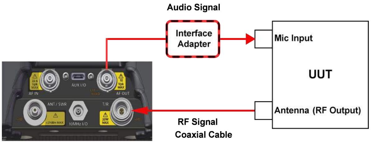
Figure 6-1 FM Transmitter Test Setup Diagram
6.2.4.2 Configure the CX100 Receiver
In this example, the CX100 RF Receiver uses the following settings:
Table 6-2 FM Transmitter Test - RF Receiver Settings
| Parameter | Setting |
| Rx Port | DUPLEX |
| Rx Frequency | 151.100000 MHz |
| Rx External Attenuator | 0.0 dB |
| Reference level | 37.0 dBm |
| Demodulation Type | FM |
| IF Bandwidth | 12.5 kHz |
| AF Filter | Band-Pass |
| Low-Pass Corner Frequency | 300 Hz |
| High-Pass Corner Frequency | 3 kHz |
| De-Emphasis | 0 μs |
To Configure the CX100 RF Receiver:
- Power on the CX100.
- Launch the RF Instrument application on the CX100.
- Select RF Test.
- Select either Duplex or Tx Test tab.

NOTE
If operating in Duplex Mode, verify RF Generator is turned OFF.
- Open the RF Receiver panel.
- RF Receiver Port: select DUPLEX.
- RF Receiver Frequency: set to 151.1 MHz.
- RF Receiver External Attenuator: set to 0.0 dB.

NOTE
The expected transmit power of the UUT is 5 Watts (37 dBm), which is well below the maximum input power of the CX100 (47 dBm), so no external attenuator is required for this test.
-
RF Receiver Reference Level: set to 37.0 dBm.
-
RF Receiver Demodulation Type: select FM.
- RF Receiver IF Bandwidth: select 12.5 kHz.

NOTE
To Calculate Proper Bandwidth
The UUT Transmitter Bandwidth can be determined with Carson's Rule (Sinusoidal Tone):
$$ 2 \times [ \text {M a x i m u m D e v i a t i o n} + \text {M a x i m u m A u s i o n F r e q u e n c y} ] $$
$$ 2 \mathrm {X} [ 3 \mathrm {k H z} + 3 \mathrm {k H z} ] = 1 2 \mathrm {k H z} $$
The formula above provides the value, which in this example is 12kHz , that is used to determine the proper setting for the CX100 IF Bandwidth. In this example, the closest CX100 IF Bandwidth greater than 12kHz is 12.5kHz IF Bandwidth, therefore, in this example procedure, 12.5kHz is selected for the CX100 RF Receiver IF Bandwidth.
AF Filter Selection
When the UUT is keyed, it generates a 67 Hz squelch tone. To determine the voice modulation level and distortion, the 67 Hz tone must be filtered out so that only the 1 kHz test tone is received by the CX100 when measuring these parameters.
In this example, a Band Pass filter is selected so that frequencies lower than 300Hz will not be received by the CX100 Receiver, and frequencies higher than 3kHz are also blocked so as not to interfere with the 1kHz test tone.
6.2.4.3 Configure the CX100 AF Function Generator
In this example, the CX100 AF Function Generator uses the following settings:
Table 6-3 FM Transmitter Test - AF Function Generator Settings
| Parameter | Setting |
| Encode Type | Single Tone |
| Coupling | AC |
| Load Impedance | HiZ |
| AF Generator 1 | |
| Frequency | 1.0000 kHz |
| Level Type | Vrms |
| Level | 0.02 V |
| Waveform | Sine |
| AF Gen 1 | OFF |
| AF Generator 2 | |
| AF Gen 2 | OFF |
To Configure the CX100 AF Function Generator:
- Open the AF Function Generator panel.
- Select the Settings soft-key.
- AF Function Generator Coupling: select AC.
- AF Function Generator Load Impedance: select HiZ.
- AF Generator 1 Frequency: set to 1 kHz (test modulation frequency).
- AF Generator 1 Level Type: select Vrms.
- AF Generator 1 Level: set to 0.02V .
- AF Generator 1 Waveform: select SINE.
- Set AF Gen 1 soft-key to OFF.
- Set AF Gen 2 soft-key to OFF.
6.2.4.4 Configure the CX100 Meters

NOTE
This example does not use upper and lower limits to define pass/fail criteria. Pass/fail criteria can be entered as upper and lower limit values in each meter menu for visual feedback of pass/fail status.
To Configure the CX100 Meters
- Open the Meters panel.
- Use the Analog Demod Measurements > Distortion/SINAD/SNR soft-key to display the Distortion Meter.
- Open the RF Power Meter configuration window.
- Upper and Lower Limit values can be assigned if pass/fail criteria are known.
- Power Meter Measurement Type: select Live.

NOTE
Before proceeding to Step 8, cease transmitting signals to the CX100.
- Set the Measurement Type on the following meters to Live:
Modulation
Distortion
AF Counter
RF Frequency Error
- Select RF Analyzer and press theNormalize key.
- Press the Run Normalize soft-key to normalize the RF Power Meter.
6.2.5 Gathering Test Data
6.2.5.1 Viewing Test Data
Open either the Test Setup Summary panel or the Meters panel.

NOTE
If upper and lower limits are being used, recommendation is to view results on the Meters panel instead of the Test Setup Summary panel in order to utilize the color coded pass/fail indicators on meters.
6.2.5.2 Test UUT Power and Frequency
- Key the UUT.
- Review the RF Power Meter reading along with overall settings.
- Review the RF Frequency Error reading.
- Unkey the UUT.
6.2.5.3 Test UUT Modulation Level and Transmitter Distortion
- Open the AF Function Generator panel.
- Set AF Gen 1 soft-key to ON.
- Open the Test Setup Summary panel.
- Key the UUT and hold.
- Review the Modulation Meter reading.
- Review the Distortion Meter reading along with overall settings.
- Unkey the UUT.
6.2.5.4 Test UUT Squelch Tone Modulation Level and Frequency
- Open the RF Receiver panel.
- Open the Test Setup Summary panel.
- Key the UUT and hold.
- Review the Modulation Meter reading.
- Review the AF Counter reading along with overall settings.
- Unkey the UUT.
6.3 AM Transmitter Testing
6.3.1 Scope of Test
This section explains how to configure the CX100 to evaluate the transmit performance of an AM device. The test setup in this section can be used to evaluate the following UUT parameters:
AM Transmitter Power
AM Transmitter Frequency
Modulation Level
Transmitter Distortion
6.3.2 UUT Parameters/Characteristics
The example in this section assumes the following UUT characteristics and settings; adjust settings according to the operational capabilities of the UUT.
Table 6-4 AM Transmitter Test - UUT Settings
| Parameter | Setting |
| Transmit Frequency | 116.5 MHz |
| Transmit Power | 50 Watts |
| Transmit Modulation | AM |
| Maximum Modulation Index | 100% |
| Maximum Modulation Frequency | 3 kHz |
| Microphone/Mod Input | DC Coupled, 600 Ohm |
| Modulation Input Level for Test Modulation | 30 mVrms |
6.3.3 Equipment Needed
The following equipment is required to perform the test procedures defined in this section:
CX100 ComXpert
- Audio cable and MIC/Audio Adapter combination capable of interfacing an audio signal from the CX100 audio output to the transmitter modulation input (typically the microphone input on the transmitter).
Two RF Coaxial Cables
10 dB RF Attenuator
6.3.4 Test Setup
6.3.4.1 Hardware Setup Diagram
Connect the CX100 and UUT as shown in Figure 6-2, then proceed to the next section.
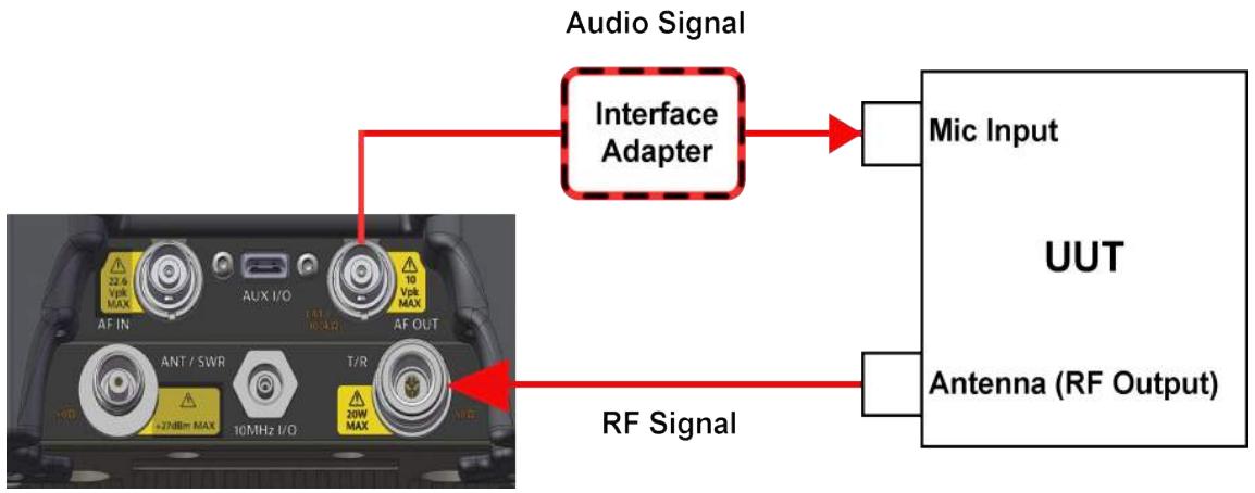
Figure 6-2 AM Transmitter Test Setup Diagram
6.3.4.2 Configure the CX100 Receiver
In this example, the CX100 RF Receiver uses the following settings:
Table 6-5 CX100 Settings - RF Receiver Settings
| Parameter | Setting |
| Rx Port | DUPLEX |
| Rx Frequency | 116.500000 MHz |
| Rx External Attenuator | 10.0 dB |
| Reference level | 37.0 dBm |
| Demodulation Type | AM |
| IF Bandwidth | 6.25 kHz |
| AF Filter | Band-Pass |
| Low-Pass Corner Frequency | 3 kHz |
| High-Pass Corner Frequency | 300 kHz |
| De-Emphasis | 0 μs |
To Configure the CX100 RF Receiver:
- Power on the CX100.
-
Launch the RF Instrument application on the CX100.
-
Select RF Test.
- Select either Duplex or Tx Test tab.

NOTE
If operating in Duplex Mode, verify RF Generator is turned OFF.
- Open the RF Receiver panel.
- RF Receiver Port: select DUPLEX.
- RF Receiver Frequency: set to 116.5 MHz.
- RF Receiver Reference Level: set to 37 dBm.

NOTE - Use of External Attenuator
The expected transmit power of the UUT is 50 Watts (47 dBm) which is the maximum input power of the CX100, so an external attenuator is required for this test.
The UUT transmits at 47 dBm through the 10 dB external attenuator, reducing the amplitude received by the CX100 to 37 dBm (5 W), therefore the Reference Level of the CX100 is set to 37 dBm so that the power measurements factor in external attenuation to reflect the actual power generated by the UUT.
- RF Receiver Demodulation Type: select AM.
- RF Receiver IF Bandwidth: select 6.25 kHz.

NOTE - IF Bandwidth Selection
For this test, the UUT will generate AM using a 1 kHz tone, which is a narrow-band signal, so the IF Bandwidth is set to the narrowest setting of 6.25 kHz.

NOTE - AF Filter Selection
The UUT distortion is specified as being measured with a 300Hz to 3kHz band pass filter, so the AF Filter field is set to Band Pass to filter.
6.3.4.3 Configure the CX100 AF Function Generator
In this example, the CX100 AF Function Generator uses the following settings:
Table 6-6 AM Transmitter Test - AF Function Generator Settings
| Parameter | Setting |
| Encode Type | Single Tone |
| Coupling | DC |
| Load Impedance | 600 Ω |
| AF Generator 1 | |
| Frequency | 1.0000 kHz |
| Level Type | Vrms |
| Level | 0.03 V |
| Waveform | Sine |
| AF Gen 1 | OFF |
| AF Generator 2 | |
| AF Gen 2 | OFF |
To Configure the CX100 AF Function Generator:
- Open the AF Function Generator panel.
- AF Function Generator Coupling: press the settings soft key and select coupling DC.
- AF Generator 1 Load Impedance: select 600 Ω.
- AF Generator 1 Frequency: set to 1 kHz.
- AF Generator 1 Level Type: select Vrms.
- AF Generator 1 Level: set to 0.03V .
- AF Generator 1 Waveform: select Sine.
- Set AF Gen 1 soft-key to OFF.
- Verify AF Gen 2 soft-key is set to OFF.
6.3.4.4 Configure the CX100 Meters

NOTE
This example does not use upper and lower limits to define pass/fail criteria. Pass/fail criteria can be entered as upper and lower limit values in each meter menu for visual feedback of pass/fail status.
RF Power Meter
- Open the Meters Configuration Window.
- Use the Analog Demod Measurements > Distortion/SINAD/SNR soft-key to display the Distortion Meter on the Meters panel.
- Open the RF Power Meter configuration window.
- Upper and Lower Limit values can be assigned if pass/fail criteria are known.
- Power Meter Measurement Type: select Live.

NOTE
Before proceeding to Step 8, cease transmitting signals to the CX100.
- Set the Measurement Type on the following meters to Live:
Modulation Meter
Distortion Meter
AF Counter Meter
RF Frequency Error Meter
- Select RF Analyzer and press theNormalize key.
- Press the Run Normalize soft-key to normalize the RF Power Meter.
6.3.5 Gather Test Data
6.3.5.1 Viewing Test Data
Open either the Test Setup Summary panel or the Meters panel.

NOTE
If upper and lower limits are being used, recommendation is to view results on the Meters panel in order to utilize the color coded pass/fail indicators on meters.
6.3.6 Test UUT Power and Frequency
- Key the UUT.
- Review the RF Power Meter reading along with overall settings.
- Review the RF Frequency Error Meter reading.
- Unkey the UUT.
6.3.7 Test UUT Modulation Level and Distortion
- Open the AF Function Generator panel.
- Set AF Gen 1 soft-key to ON.
- Open the Test Setup Summary panel.
- Key the UUT and hold.
- Review the Modulation Meter reading.
- Review the Distortion Meter reading along with overall settings
- Unkey the UUT.
6.4 FM Receiver Performance Tests
6.4.1 Scope of Test
This test is used to evaluate the following performance characteristics of an FM Receiver:
Radio Receive Sensitivity
Squelch Tone Response
Audio Level
6.4.2 UUT Parameters/Characteristics
The example in this section assumes the following UUT characteristics and settings; adjust settings according to the operational capabilities of the UUT.
Table 6-7 FM Receiver Test - UUT Parameters
| Parameter | Setting |
| FM Receiver | Narrowband |
| FM Receiver Frequency | 151.1 MHz |
| Rate Deviation | 2.5 kHz |
| Distortion | Less than 1% at 700 mV audio level |
| 12 dB SINAD | -118 dBm |
| Squelch Tone Deviation | 350 Hz |
| Squelch Tone Frequency | 67 Hz |
6.4.3 Equipment Needed
The following equipment is required to perform the test procedures defined in this section:
CX100 ComXpert
- Audio cable and MIC/Audio Adapter combination capable of interfacing an audio signal from the UUT demodulated output (typically speaker out signal) to the CX100 audio input connector.
RF Coaxial Cable
6.4.4 Test Setup
6.4.4.1 Hardware Setup Diagram
Connect the CX100 and UUT as shown in Figure 6-3, then proceed to the next section.
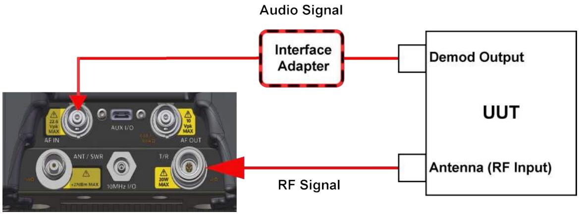
Figure 6-3 FM Receiver Test Setup Diagram
6.4.4.2 Configure the CX100 RF Generator
In this example, the CX100 RF Generator uses the following settings:
Table 6-8 CX100 Settings - RF Generator Settings
| RF Generator | |
| Frequency | 151.100000 MHz |
| Output Level | -50 dBm |
To Configure the CX100 RF Generator:
- Power on the CX100.
- Launch the RF Instrument application on the CX100.
- Select RF Test.
- Select either Duplex or Rx Test tab.
- Open the RF Generator panel.
- RF Generator Frequency: set to 151.1 MHz.
- RF Generator Output Level: set to -50 dBm.
- Turn on RF Generator.
6.4.4.3 Configure the CX100 Modulation Generators
In this example, the CX100 Modulation Generators use the following settings:
Table 6-9 FM Receiver Test- Modulation Generator Settings
| Modulation Generator 1 | |
| Type | FM |
| Deviation | 1.8 kHz |
| Rate | 1 kHz |
| Waveform | Sine |
| Mod 1 soft-key | Mod 1 ON |
| Modulation Generator 2 | |
| Type | FM |
| Deviation | 350 Hz |
| Rate | 0.067 kHz |
| Waveform | Sine |
| Mod 2 soft-key | Mod 2 ON |
| External Modulation | |
| Mod Ext soft-key | Mod Ext OFF |
To Configure the CX100 Modulation Generators:
- Open the Modulation Generator 1 panel.
- Modulation Generator 1 Modulation Type: select FM.
- Modulation Generator 1 Deviation: set to 1.8kHz (60% of 2.5 kHz max deviation rating of radio).
- Modulation Generator 1 Rate: set to 1.000kHz
- Modulation Generator 1 Waveform: select Sine.
- Mod 1 soft-key: set to ON.
- Open the Modulation Generator 2 panel.
- Modulation Generator 2 Modulation Type: select FM.
- Modulation Generator 2 Deviation: set to 350Hz
- Modulation Generator 2 Rate: set to 0.0670 kHz.
- Modulation Generator 2 Waveform: select Sine.
-
Mod 2 soft-key: set to ON.
-
Open the External Modulation panel.
- Mod Ext soft-key: set to OFF.
6.4.5 Configure the CX100 Meters

NOTE
Meter parameters should be configured according to UUT performance characteristics and test requirements.
In this example, the CX100 Meters are configured as follows:
Table 6-10 FM Receiver Test - Meter Settings
| SINAD Meter | |
| Enable Lower Limit | Enabled |
| Lower Limit | 12.0 dB |
| Measurement Type | Average |
| Average Count | 20 |
| Distortion Meter | |
| Enable Upper Limit | Enabled |
| Upper Limit | 1% |
| Measurement Type | Live |
| Audio Level Meter | |
| Enable Upper Limit | Enabled |
| Upper Limit | +0.710 V |
| Enable Lower Limit | Enabled |
| Lower Limit | +0.690 V |
| Measurement Type | Live |
| AF Counter | |
| Enable Upper Limit | Disabled |
| Enable Lower Limit | Disabled |
| Measurement Type | Live |
To Configure the CX100 Meters:
- Open the Meters panel.
- Use the Audio Measurements > Distortion/SINAD/SNR soft-key to display the SINAD Meter on the Meters panel.
- Open the SINAD Meter configuration window.
- Enable the Lower Limit.
- Set the Lower Limit to 12.0 dB.
- Select Average from the Measurement Type menu.
- Set Average Count to 20.
- Close the SINAD Meter configuration window.
- Use the Audio Measurements > Distortion/SINAD soft-key to display the Distortion Meter.
- Open the Distortion Meter configuration window.
- Enable the Upper Limit.
- Set the Upper Limit to 1% .
- Select Live from the Measurement Type menu.
- Close the Distortion Meter configuration window.
- Open the Audio Level Meter configuration window.
- Enable the Upper Limit.
- Set the Upper Limit to +0.710V
- Enable the Lower Limit.
- Set the Lower Limit to +0.690V
- Select Live from the Measurement Type menu.
- Close the Audio Level Meter configuration window.
- Set the Audio Level Meter Vrms/Vpp toggle soft-key to Vrms.
- Open the AF Counter Meter configuration window.
- Select Live from the Measurement Type menu.
- Close the AF Counter Meter configuration window.
6.4.6 Gather Test Data
6.4.6.1 Viewing Test Data
Open either the Test Setup Summary panel or the Meters panel.

NOTE
If upper and lower limits are being used, recommendation is to view results on the Meters panel in order to utilize the color coded pass/fail indicators on meters.
6.4.6.2 UUT Audio Level and Distortion Tests
- Adjust the UUT volume until the Audio Level Meter displays approximately 700 mV and the meter background color is green and the pass icon is displayed.
- Verify the Distortion Meter displays less than 1% distortion and the meter background color is green and the pass icon is displayed.
6.4.6.3 UUT Squelch Tone Function Tests
- Turn Mod 2 soft-key to OFF.
- Observe the Audio Level Meter to verify the UUT is quieted, and that the AF Counter does not display 1.000 kHz audio.
- Turn Mod 2 soft-key to ON.
- Use the Audio Level Meter to verify the UUT is demodulating the CX100 modulation, and that the AF Counter displays 1.000kHz audio.
6.4.6.4 UUT Receiver Sensitivity Tests
- Set the CX100 RF Generator Level to -118.000 dBm.
- Audio Measurements > Distortion/SINAD soft-key - select SINAD to display the SINAD Meter on the Rx Test Meters panel.
- Press the Rx Test Meters Clear/Reset soft-key.
- Observe the SINAD Meter and verify its reading is 12 ~dB or greater, and that the meter background color is green and the pass icon is displayed.
6.5 AM Receiver Tests
6.5.1 Scope of Test
This test is used to evaluate the following performance characteristics of an AM Receiver:
Radio Receive Sensitivity
Squelch Tone Response
Audio Level
6.5.2 UUT Parameters/Characteristics
The example in this section assumes the following UUT characteristics and settings; adjust settings according to the operational capabilities of the UUT.
Table 6-11 AM Receiver Test - UUT Parameters
| Parameter | Setting |
| AM Receiver | Narrowband |
| AM Receiver Frequency | 151.1 MHz |
| Distortion | Less than 1% at 700 mV audio level |
| 12 dB SINAD | -118 dBm |
6.5.3 Required Equipment
The following equipment is required to perform the test procedures defined in this section:
CX100 ComXpert
- Audio cable and MIC/Audio Adapter combination capable of interfacing an audio signal from the UUT demodulated output (typically speaker out signal) to the CX100 audio input connector.
RF Coaxial Cable
6.5.4 Configuring the Equipment
6.5.4.1 Hardware Configuration
Connect the CX100 and UUT as shown in Figure 6-4, then proceed to the next section.
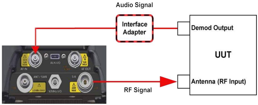
Figure 6-4 AM Receiver Test - Setup Diagram
6.5.4.2 Set Up the CX100 RF Generator
In this example, the CX100 RF Generator uses the following settings:
Table 6-12 AM Receiver Test - RF Generator Settings
| RF Generator | |
| Frequency | 151.100000 MHz |
| Output Level | -50 dBm |
To Set Up the CX100 RF Generator:
- Power on the CX100.
- Launch the RF Instrument application on the CX100.
- Select RF Test.
- Select either Duplex or Rx Test tab.
- Open the RF Generator panel.
- RF Generator Frequency: set to 151.1 MHz.
- RF Generator Output Level: set to -50 dBm.
6.5.4.3 Set Up the CX100 Modulation Generators
In this example, the CX100 Modulation Generators use the following settings:
Table 6-13 AM Receiver Test - Modulation Generator Settings
| Modulation Generator 1 | |
| Type | AM |
| Rate | 1 kHz |
| Depth | 60% |
| Waveform | Sine |
| Mod 1 soft-key | Mod 1 ON |
| Modulation Generator 2 | |
| Type | AM |
| Rate | 0.067 kHz |
| Depth | 50% |
| Waveform | Sine |
| Mod 2 soft-key | Mod 1 ON |
| External Modulation | |
| Mod Ext soft-key | Mod Ext OFF |
To Set Up the CX100 Modulation Generators:
- Open the Modulation Generator 1 panel.
- Modulation Generator 1 Modulation Type: select AM.
- Modulation Generator 1 Rate: set to 1.000kHz .
- Modulation Generator 1 Depth: set to 60% .
- Modulation Generator 1 Waveform: select Sine.
- Mod 1 soft-key: set to ON.
- Open the Modulation Generator 2 panel.
- Mod 2 soft-key: set to OFF.
- Open the External Modulation panel.
- Mod Ext soft-key: set to OFF.
6.5.5 Configure CX100 Meters

NOTE
Meter parameters should be configured according to UUT performance characteristics and test requirements.
In this example, the CX100 Meters are configured as follows:
Table 6-14 AM Receiver Test - Meter Settings
| SINAD Meter | |
| Enable Lower Limit | Enabled |
| Lower Limit | 10.0 dB |
| Measurement Type | Average |
| Average Count | 20 |
| Distortion Meter | |
| Upper Lower Limit | Enabled |
| Upper Limit | 1% |
| Measurement Type | Live |
| Audio Level Meter | |
| Enable Upper Limit | Enabled |
| Upper Limit | +0.710 V |
| Enable Lower Limit | Enabled |
| Lower Limit | +0.690 V |
| Measurement Type | Live |
| AF Counter | |
| Enable Upper Limit | Disabled |
| Upper Limit | N/A |
| Enable Lower Limit | Disabled |
| Measurement Type | Live |
To Set Up the CX100 Meters:
- Open the Meters panel.
- Use the Audio Measurements > Distortion/SINAD soft-key to display the SINAD Meter.
- Open the SINAD Meter configuration window.
- Enable the Lower Limit.
- Set the Lower Limit to 12.0 dB.
- Select Average from the Measurement Type menu.
- Set Average Count to 20.
- Close the SINAD Meter configuration window.
- Use the Audio Measurements > Distortion/SINAD soft-key to display the Distortion Meter.
- Open the Distortion Meter configuration window.
- Enable the Upper Limit.
- Set the Upper Limit to 1% .
- Select Live from the Measurement Type menu.
- Close the Distortion Meter configuration window.
- Open the Audio Level Meter configuration window.
- Enable the Upper Limit.
- Set the Upper Limit to +0.710V
- Enable the Lower Limit.
- Set the Lower Limit to +0.690V
- Select Live from the Measurement Type menu.
- Close the Audio Level Meter configuration window.
- Set the Audio Level Meter Vrms/Vpp toggle soft-key to Vrms.
- Open the AF Counter Meter configuration window.
- Select Live from the Measurement Type menu.
- Close the AF Counter Meter configuration window.
6.5.6 Gather Test Data
6.5.6.1 Viewing Test Data
Open either the Test Setup Summary panel or the Meters panel.

NOTE
If upper and lower limits are being used, recommendation is to view results on the Meters panel in order to utilize the color coded pass/fail indicators on meters.
6.5.6.2 Test UUT Audio Level and Distortion
- Adjust the UUT volume until the Audio Level meter displays reading around 700 mV and the meter background color is green and the pass icon is displayed.
- Verify the Distortion meter reading is less than 1% Distortion and that the background color is green and the pass icon is displayed.
6.5.6.3 Test UUT Receiver Sensitivity
- Change the CX100 RF Generator Level to -118.000 dBm.
- Use the Audio Measurements > Distortion/SINAD soft-key to display the SINAD Meter on the Rx Test Meters panel.
- Press the Rx Test Meters Clear/Reset soft-key.
- Observe the SINAD Meter and verify its reading is 12 ~dB or greater, and that the meter background color is green and the pass icon is displayed.
6.6 Performing VSWR/DTF Testing
6.6.1 Scope of Test
This test is used to evaluate how well an antenna's impedance matches the impedance of the radio or transmission line to which it is connected.
6.6.2 UUT Parameters/Characteristics
The example in this section assumes the following UUT characteristics and settings; adjust settings according to the operational capabilities of the UUT.
Table 6-15 VSWR Test - Example Cable Characteristics
| Parameter | Setting |
| Frequency Range | 30 to 85 MHz |
6.6.3 Equipment Needed
The following equipment is required to perform the procedures defined in this section:
CX100 ComXpert
- Cable to be tested
- Calibration Kit
6.6.4 Calibrate the CX100 Before VSWR Testing
6.6.4.1 Hardware Setup Diagram
Connect the CX100 and UUT as shown in Figure 6-5, then proceed to the next section.
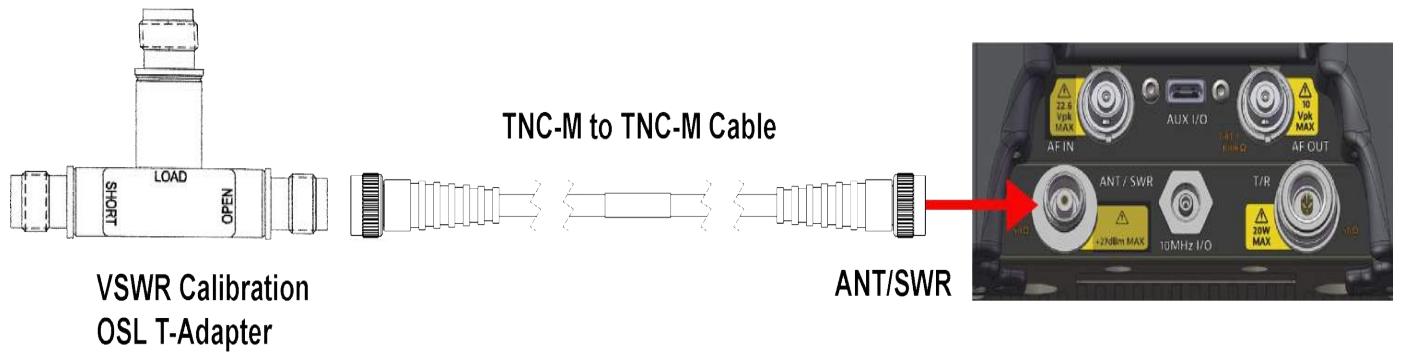
Figure 6-5 VSWR Calibration Setup Diagram
6.6.4.2 Running VSWR Calibration
- Power on the CX100.
- Select the Home icon on the CX100.
- Select the RF Instrument tab at the top of the application on the CX100 screen.
- Select VSWR/DTF.
- Select the VSWR tab.
- Open the Instrument Settings menu.
- Press the Calibrate soft-key.
- Select External Standards. Select OK button to confirm.
- Follow the instructions on the UI to configure the device for external calibration.
- Press the OK button to run the calibration. See Figure 6-6.
- When external calibration has been completed, the calibration plot should resemble data in Figure 6-6.
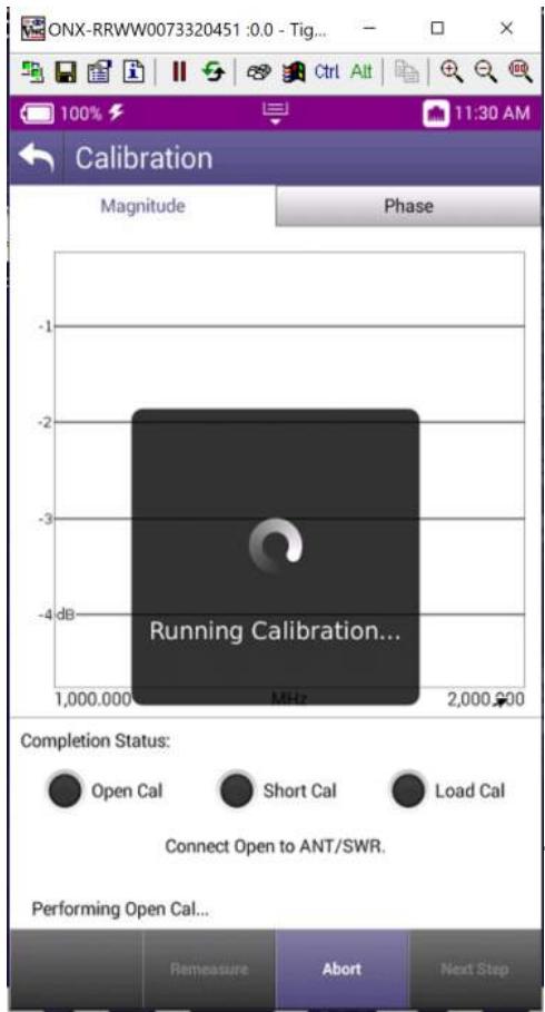
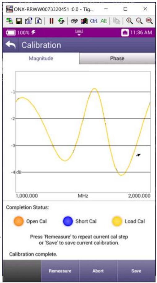
Figure 6-6 Calibration running and complete
6.6.5 To Perform VSWR Test
6.6.5.1 Hardware Setup Diagram
Connect the CX100 and UUT as shown in Figure 6-7, then proceed to the next section.
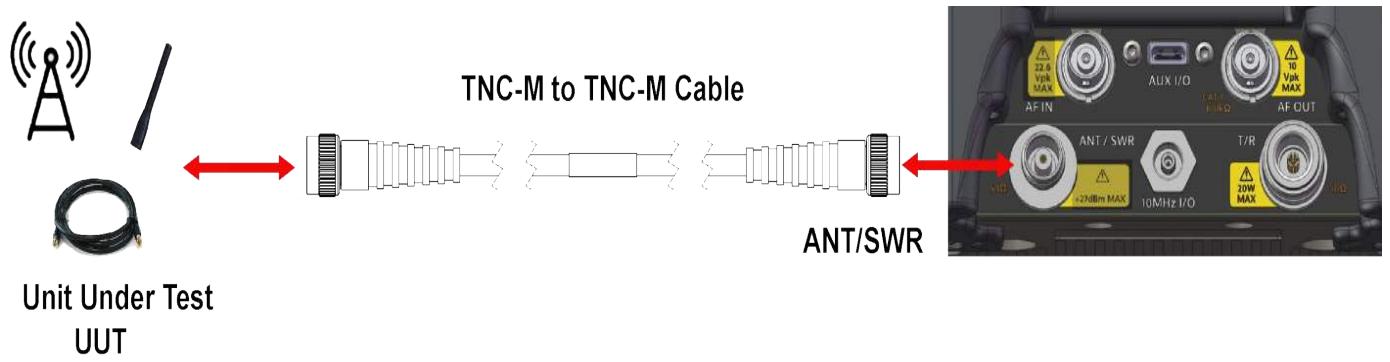
Figure 6-7 VSWR Test Setup Diagram
6.6.5.2 Configure the CX100 VSWR Settings
In this example, the CX100 uses the following VSWR settings:
Table 6-16 CX100 VSWR Test Settings
| Parameter | Setting |
| Start Frequency | 20 MHz |
| Stop Frequency | 100 MHz |
| Step Frequency | 100 (points) |
To Configure the CX100 for VSWR Test
- Power on the CX100.
- Select the RF Instrument tab at the top of the application on the CX100 screen.
- Select VSWR/DTF.
- Select the VSWR tab.
- Open the Instrument Settings menu.
- Set the Start Frequency to 20 MHz.
- Set the Stop Frequency to 100 MHz.
-
Set measurement mode to VSWR and Press the OK button.
-
Ensure the VSWR soft key is set to VSWR On.
6.6.5.3 Gather Test Data
To Gather Test Data
This is used to gather the required Test Data.
- Observe the VSWR trace.
- Adjust the markers to display the VSWR measurement at the desired frequency.
- To observe Return Loss measurement, open the Instrument Settings menu and set the measurement mode to Return Loss.
6.7 Performing Distance to Fault (DTF) Tests
6.7.1 Scope of Test
Distance to Fault (DTF) measurements, provides the capability to analyze, troubleshoot and identify signal path degradation in cables and transmission lines. Faults are a result of conditions such as poor connections, damaged cables, or faulty antennas.
This test is used to evaluate the following performance issues:
The distance to fault of a coaxial cable.
6.7.2 UUT Parameters/Characteristics
The example in this section assumes the following UUT characteristics and settings; adjust settings according to the operational capabilities of the UUT.
Table 6-17 DTF Test - Example Cable Characteristics
| Parameter | Setting |
| Coaxial cable type | RG58 |
| Coaxial cable length | 20 ft |
6.7.3 Equipment Needed
The following equipment is required to perform the test procedures defined in this section:
CX100 ComXpert
- Cable to best tested
6.7.4 Configuring the Equipment
6.7.4.1 Hardware Setup Diagram
Connect the CX100 and UUT as shown in Figure 6-8, then proceed to the next section.
Figure 6-8 DTF Test Setup Diagram
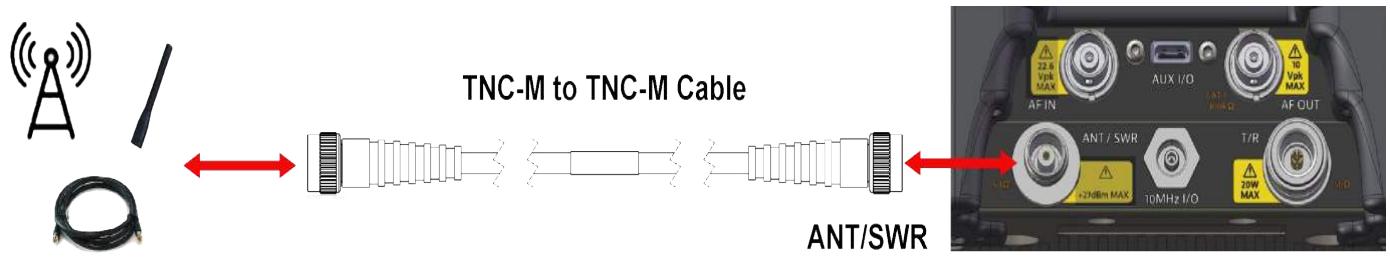
Unit Under Test UUT
6.7.4.2 Configure the CX100 DTF Settings
In this example, the CX100 uses the following DTF settings:
Table 6-18 DTF Test Settings
| Parameter | Setting |
| Start Frequency | 20 MHz |
| Stop Frequency | 100 MHz |
| Step Frequency | 100 (points) |
To Configure the CX100
- Power on the CX100.
- Launch the RF Instrument application on the CX100.
- Select VSWR/DTF.
- Select RG-58 cable type.
- Select the cable file to be used for the test.
- Select the DTF tab.
- Open the instrument settings menu.
- Set measurement mode to Return Loss
- Select the distance key.
-
Set the start distance to 1 ft.
-
Set the stop distance to 30 ft.
- Set number of points to 500.
- Close the instrument settings tab and ensure the DTF enable soft key displays DTF on. See Figure 6-9 and Figure 6-10 for screen examples.
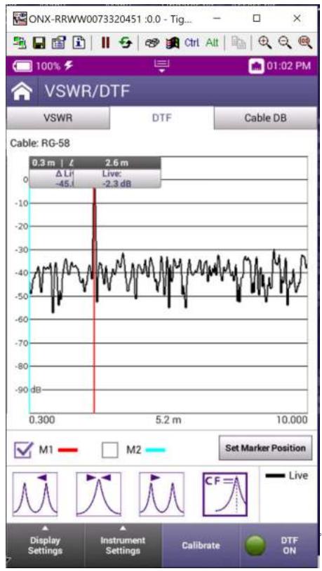
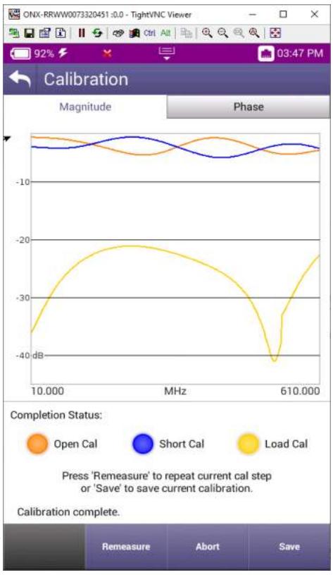
Figure 6-9 DTF (Distance to Fault) and Calibration
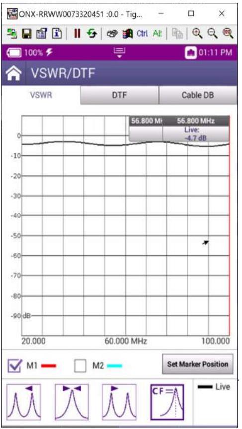
Figure 6-10 Return Loss
6.7.4.3 Gather Test Data
To Gather Test Data
This is used to gather the required Test Data.
- Observe DTF trace.
- See Figure 6-9 for screen example.
Managing Files and Reports
This chapter describes how to generate reports and manage file transfer to and from the CX100. This chapter reviews the following information:
-
Generating Reports 7-2
-
Custom Report Fields 7-2
Enforcing Report Entry 7-3
Saving a Report 7-3
Managing Files. 7-4
- Accessing the File Browser. 7-4
- Selecting Files or Folders 7-5
- Opening Files or Folders 7-5
- Copying and Pasting Files or Folders 7-5
- Downloading Files via Web Browser. 7-6
- Uploading Files Using FTP/HTTP 7-6
Viewing the User's Guide on the Device 7-6
7.1 Generating Reports
Test results, configuration settings and graphs can be saved as a report using the Save Report function. The Save Report function creates reports based on the configuration settings and test results for the currently active test.

NOTE
The Save Reports button is only enabled when a test is active; the button is disabled unless a test is running.
7.1.1 Custom Report Fields
When a test report is saved, values can be configured for up to five custom "customer" report fields and five custom "technician" report fields. The values that are specified for the fields are included in the generated report output.

NOTE
Custom fields are available for selection in associated StrataSync templates.
To Add Custom Report Fields
- Navigate to the Save Report menu (Utility Tray > Save Report button).
-
Perform one of the following:
-
To select and specify values for custom customer fields, select Add Customer Report Fields. The Customer Information menu appears.
-
To select and specify values for custom technician fields, select Add Technician Report Fields. The Technician Information menu appears.
-
Perform the following to create up to five custom customer fields and up to five custom technician fields:
a Press the field(s) that you want to include in your report.
b The field is selected and displayed on the Customer Information menu with a check mark (indicating that it has been selected for the report).
c Select the field to display a data entry screen.
d Enter a value for the field, then press OK.
e The specified value appears directly under the field name on the Customer Information menu.
7.1.2 Enforcing Report Entry
The test set can be configured to require that custom report fields be populated before generating and saving a report.
To Require Report Field Entry
- Open the System Settings menu.
- Select the check box next to Enforce Report Field Entry.
- Press the Back button to save and exit the menu.
Entry of values for the custom report fields will be required before a report is saved.
7.1.3 Saving a Report
To Save a Report
- Open the Utility Tray.
- Select the Save Report button. The Save Report window is displayed.
- Enter the name of the report. The default file name uses the type of test followed by a three-digit number that increments with each file saved (for example, cablecheck001 or DSL002).
- Specify the format (PDF, XML, or HTML).

NOTE
VIAVI offers a proprietary XML schema definition file (XSD) available online (referenced in the XML report).
- To include custom fields in the report, enable, then specify values for the fields.
- To immediately view the report, select Save and View.
- To save the report without viewing it, select Save.
The current test results, configuration settings, and, if applicable, graphs and custom report fields are saved as a report. If "Save and View" was selected, the report output also appears on the UI.
Technician report values will be saved until the values are changed. Custom report fields need to be completed for every test report saved, but you can apply the values specified the last time the report was saved.
7.1.4 Viewing a Report
Saved reports can be viewed on the device's UI.

NOTE
The View Report button is disabled when there are no reports saved on the device.
To View a Report
- Open the Utility Tray.
- Select View Report button. A View Report window appears, showing all of the saved reports.
- Select a report to view. The report is displayed on the screen.
7.2 Managing Files
The CX100 File Browser is used to open, rename, copy, or delete saved result files, screen shots, or other files stored on device, or on a USB flash drive that is connected to device.

NOTE
When copying files to the device, note the available memory on the device's hard-drive. If the device's hard-drive is selected as the save location for all test results, and there is insufficient space available on the device's internal hard-drive, the device will not be able to save test data and test data may be lost.
7.2.1 Accessing the File Browser
Files are copied to and from the device using the File Browser.
To Open the File Browser
- Open the Utility Tray.
- Select the File Browser button.
7.2.2 Selecting Files or Folders
To select one or more files or folders
- Open the File Browser. See section 7.2.1, "Accessing the File Browser", on page 7-4.
- Use the up and down arrow keys to navigate folders or files.
- Perform the one of the following to select a folder:
To select a single file or folder, select the check box to the left of the file or folder.
To select multiple files or folders (for example, to copy multiple files to USB, or upload multiple files using FTP/ HTTP), touch the check box to the left of each folder.
4. The files or folders are selected.
7.2.3 Opening Files or Folders
To Open a File or Folder
- Open the File Browser. See section 7.2.1, "Accessing the File Browser", on page 7-4.
- Select a file or folder. See section 7.2.2, "Selecting Files or Folders", on page 7-5.
- Select the Open button. The contents of the folder appear or the file is displayed on the screen.
7.2.4 Copying and Pasting Files or Folders
To Copy Files or Folders
- Open the File Browser. See section 7.2.1, "Accessing the File Browser", on page 7-4.
- Select a file or folder. See section 7.2.2, "Selecting Files or Folders", on page 7-5.
-
Press the File Options system key and perform one of the following:
-
Select Copy, navigate to another folder or drive.
- Press the File Options key, then select Paste.
- Select either Copy to USB if you are using File Browser, or Copy to Internal if you are using the USB File Browser.
The file is copied and the File Browser menu appears.
7.2.5 Downloading Files via Web Browser
To Download Files from CX100 via Web Browser
- Connect the CX100 to a network. See section 4.4, "Establishing a Network Connection", on page 4-10.
- Record the CX100's IP Address.
- Navigate to the Remote screen (System Settings > Remote).
- Select the Enable HTTP File Server check box.
- Open a web browser window.
- Enter the CX100's IP Address in the web browser URL field.
7.2.6 Uploading Files Using FTP/HTTP
To Upload Files
- Open the File Browser. See section 7.2.1, "Accessing the File Browser", on page 7-4.
- Select a file or folder. See section 7.2.2, "Selecting Files or Folders", on page 7-5.
- Select File Options.
- Select Upload FTP/HTTP.
- The Upload settings appear. Specify the Upload URL, User name, and Password.
- Select the Apply button to start the upload.
- When the upload finishes, a message appears stating that the selected files were uploaded. Press OK to close the dialog window.
7.3 Viewing the User's Guide on the Device
The CX100 Operation Manual can be viewed in PDF format on the device. The file must be located on a USB memory device or copied to the CX100 using File Manager.
To View the Product Manual
- Open the File Browser. See section 7.2.1, "Accessing the File Browser", on page 7-4.
- Navigate to the directory containing the pdf file.
- Select the file name to open the document.
- The PDF reader application launches the document.
Care, Maintenance, and Troubleshooting
This chapter reviews storage and shipping instructions as well as care and maintenance procedures for the CX100 ComXpert as well as operator level troubleshooting procedures. This chapter reviews the following topics:
Recharging the Battery 8-2
- Replacing the Battery. 8-2
- Storing the Module. 8-2
Shipping Instructions 8-2
- Return Material Authorization (RMA) 8-3
- Tagging the Device 8-3
Shipping Containers 8-3
Freight Costs 8-3 - Packing Procedure 8-4
Operator Level Maintenance 8-5
Visual Inspections 8-5
External Cleaning 8-5
- Updating Software 8-6
CX100 ComXpert Self Test Procedure 8-6
-
Troubleshooting 8-7
-
Troubleshooting Symptom Index 8-7
- Troubleshooting Procedures 8-8
8.1 Recharging the Battery
The CX100 is designed to be powered by an internal battery or by an external AC power supply. The internal battery supports up to 3 hours of continuous operation, after which time the battery needs recharging.
To recharge the battery
- Connect the power cord to the AC Adapter/Charger.
- Connect the DC connector to the device's DC Input Connector. See section 1.5.9, "DC Input Connector", on page 1-10 for information.
- Connect the power cord to a grounded AC power supply.
- Verify the device's Battery LED flashes green to indicate the battery is charging.
- The Battery LED turns and stays green when the battery is fully charged.

CAUTION
Do not use the power cord if it is damaged or frayed. Replace damaged power cords with cable of the same ratings.
Do not position the power cord in a manner that makes it difficult to disconnect from the main voltage.
Do not allow anything to rest on the power cord.
Do not locate the product where persons can walk on or trip over the power cord.
8.2 Replacing the Battery
The CX100's RF Module and internal components are ESD sensitive and can be damaged by disassembling the device in a non-ESD environment. For this reason, the device's battery should only be replaced by qualified service personnel.
See section B.2, "Battery Replacement Information", on page B-2 for battery replacement instructions.
8.3 Storing the Module
Store the module in a clean, dry place according to product specifications.
8.4 Shipping Instructions
Any device returned to factory for calibration, service or repair must be repackaged and shipped subject to the following conditions:
8.4.1 Return Material Authorization (RMA)
Do not return any products to the factory without prior authorization from VIAVI.
Refer to the following links for relevant information:
To request an RMA
https://www.viavisolutions.com/en-us/support/customer-care/return-material-authorization-rma-requesRF Duplexma-request-avionics-radio-test-us
For general shipping information
https://www.viavisolutions.com/en-us/general-shipping-instructions-avionics-radio-test-rmas
8.4.2 Tagging the Device
All items shipped to VIAVI must be tagged with:
Owner's Identification and contact information
Nature of service or repair needed
Model Number and Serial Number
- Return Authorization (RA) Number
8.4.3 Shipping Containers
Devices must be repackaged in original shipping containers using VIAVI packing materials. If original shipping containers and materials are not available, contact VIAVI for shipping instructions. Failure to properly package items being returned for warranty repair voids product warranty.
8.4.4 Freight Costs
All freight costs on non-warranty shipments are assumed by the customer. VIAVI recommends that customers obtain freight insurance with the freight carrier when shipping the device. VIAVI is not responsible for cost of repairs for damages that occur during shipment on warranty or non-warranty items.
8.4.5 Packing Procedure
8.4.5.1 Packaging CX100 for Shipping
The following procedure is for shipping the CX100 or the OneExpert base.
How to Package the device for Shipping
- Contact VIAVI to obtain a Return Authorization number, return address and for questions about proper packaging.
- Tag the device.
- Place device between foam inserts.
- Place secured device in shipping container.
- Seal shipping container with tape.
- Include Return Authorization number on the packaging label.
8.4.5.2 Packaging Module for Shipping
The following procedure is for shipping the RF Module independently from the base unit.
How to package the Module for shipping
- Contact VIAVI to obtain a Return Authorization number, return address and for questions about proper packaging.
- Tag the Module.
- Place Module in ESD protective packaging.
- Place packaged Module between foam inserts.
- Place secured Module in shipping container.
- Seal shipping container with tape.
- Include Return Authorization number on the packaging label.

CAUTION
Modules are ESD sensitive and should only be installed, removed and/or serviced by Qualified Service Personnel.
Mise en Garde
The following procedures may be performed by the Operator. All other service must be performed by Qualified Service Personnel.

CAUTION
This device does not contain user serviceable parts. Servicing should only be performed by Qualified Service Personnel.
Mise en Garde
Do not operate this device with the case/cover open. Opening the case/cover exposes the operator to electrical hazards which can result in electrical shock or damage to the device.
Mise en Garde
Visual inspections should be performed periodically depending on operating environment, maintenance and use.
- Check for presence and condition of all warning labels and markings and supplied safety information.
Inspect connectors for dirt, dust, corrosion or rust. - Inspect the device and accessories for damage. Do not use if there is damage to the exterior of the unit or power accessories.
8.5.2 External Cleaning
- Remove grease, fungus and ground-in dirt from surfaces with soft lint-free cloth dampened (not soaked) with isopropyl alcohol.
- Remove dust and dirt from connectors with soft-bristled brush.
- When not in use, cover the connectors with suitable dust cover to prevent tarnishing of connector contacts.
8.5.3 Updating Software
The device is shipped from the factory with the operating system and firmware installed in the device. Regular checks should be performed to ensure the device contains the most current software, drivers and or firmware.
See section 4.7, "Updating the Device's Software", on page 4-18 for instructions to update system software.
8.5.4 CX100 ComXpert Self Test Procedure
The CX100 has an automated Built-in-Test (BIT) procedure, referred to as a Self Test, which evaluates system operation to ensure the device is operating properly.
To Run the Self Test Procedure
- Launch the AutoTest function (Home > RF Instrument > Autotest button).
- Select the File Field located at the top of the screen.
- Select Self Test from the test list.
- If desired, enter name in the Operator field.
- Press the Select All soft-key.
- Press the Run Selected soft-key.
- Wait while the device performs a series of automated test process. Do not interrupt this process of the self test will fail.
- Status indicators show when self test is finished.

NOTE
Self Test is intended to verify the device is operating properly; Self Test does not verify that the device is operating to performance specifications.
8.6 Troubleshooting
This sections lists Operator Level corrective actions for malfunctions which may occur during normal device operation. This section cannot list all malfunctions that may occur, nor all tests or inspections and corrective actions. Perform tests/inspections and corrective actions in order listed. If a malfunction is not listed, or is not corrected by the listed corrective actions, contact customer support.
8.6.1 Troubleshooting Symptom Index
Description
Device does not power on when operating on battery power. 8-8
Device does not power on when connected to an AC power supply. 8-8
No receiving a signal at ANT/SWR or DUPLEX connector. 8-9
No generator output at ANT/SWR or DUPLEX Connector. 8-11
No input signal received at Audio In connector. 8-11
No signal output at Audio Out connector. 8-12
No input signal received or trace frozen on the Spectrum Analyzer. 8-12
8.6.2 Troubleshooting Procedures
MALFUNCTION
TEST OR INSPECTION
CORRECTIVE ACTION
Device does not power on when operating on battery power.
1 Is the battery charged?
No, charge battery. If problem persists, proceed to next step.
Yes, proceed to next step.
2 Is battery properly installed and seated in battery chamber?
- No, reinstall battery. If problem persists, proceed to next step.
- Yes, contact VIAVI's Technical Assistance Center (TAC).
3 Does the test set power on when connected to an AC Power Supply?
No, contact TAC.
- Yes - probable cause of failure is old or defective battery. Contact TAC.
Device does not power on when connected to an AC power supply.
1 Is the AC Power Adapter/power cord the approved part for the device?
- No, use approved part. If problem persists, proceed to next step.
Yes, proceed to next step
2 Is AC/DC Power Adapter cord securely connected to device and AC power supply?
- No, secure AC/DC Power Adapter cord. If problem persists, proceed to next step.
Yes, proceed to next step.
3 Is AC/DC Power Adapter connected correct rated power supply?
- No, connect to correct power supply. If problem persists, proceed to next step.
Yes, proceed to next step.
MALFUNCTION
TEST OR INSPECTION
CORRECTIVE ACTION
If a charged, CX100 lithium battery is available, perform the following:
4 Install battery in the test set. Does the test set power on?
- Yes, probable cause is failure at AC/DC input connector, contact TAC.
No, contact TAC.
Display touchscreen is unresponsive.
1 Reboot device.
2 If the device is configure for VNC access, determine if the UI is operable using a VNC viewing application.
No receiving a signal at ANT/SWR or DUPLEX connector.
1 Is test set Receiver Port set to correct input (ANT/SWR or DUPLEX)?
- No, set Receiver Port to correct input. If problem persists, proceed to next step.
Yes, proceed to next step.
MALFUNCTION
TEST OR INSPECTION
CORRECTIVE ACTION
2 Is cable properly connected to selected connector (ANT/SWR or DUPLEX)?
- No, properly connect cable. If problem persists, proceed to next step.
Yes, proceed to next step.
3 Is test set Receiver Frequency set to expected receive frequency?
- No, set Receiver Frequency to correct frequency. If problem persists, proceed to next step.
Yes, proceed to next step.
4 Is test set Receiver Bandwidth set appropriately for input signal type?
- No, set Receiver Bandwidth correctly. If problem persists, proceed to next step.
Yes, proceed to next step.
5 Is test set Receiver Reference Level set appropriately for the input signal?
- No, set Receiver Reference Level correctly. If problem persists, proceed to next step.
Yes, proceed to next step.
6 Is Frequency Reference set to External?
- No, connect a valid external reference. If problem persists, contact TAC.
- Yes, verify a valid source is connected to the test set's the 10 MHz Frequency Reference connector. If yes, contact TAC.
MALFUNCTION
TEST OR INSPECTION
CORRECTIVE ACTION
No generator output at ANT/SWR or DUPLEX Connector.
1 Is correct output connector selected on device (ANT/SWR or DUPLEX)?
- No, select correct output connector. If problem persists, proceed to next step.
Yes, proceed to next step.
2 Is RF Generator output turned ON?
- No, turn on RF Generator. If problem persists, proceed to next step.
Yes, proceed to next step.
3 Is RF Generator Frequency set to correct frequency?
- No, set RF Generator Frequency to correct frequency. If problem persists, proceed to next step.
Yes, proceed to next step.
4 Is RF Generator Level set appropriately for UUT?
- No, set RF Generator Level to correct setting. If problem persists, contact TAC.
Yes, contact TAC.
No input signal received at Audio In connector.
1 Is input cable properly connected to Audio In connector?
- No, properly connect the cable. If problem persists, proceed to next step.
Yes, proceed to next step.
2 Are Audio In settings appropriate for the characteristics of the incoming audio signal (e.g. Range, Coupling, Input Sensitivity)?
No, adjust settings. If problem persists, contact TAC.
Yes, contact TAC.
MALFUNCTION
TEST OR INSPECTION
CORRECTIVE ACTION
No signal output at Audio Out connector.
1 Is CX100 AF Generator enabled?
- No, turn on AF Generator. If problem persists, proceed to next step.
Yes, proceed to next step.
2 Is cable properly connected to Audio Output Connector?
- No, properly connect the cable. If problem persists, proceed to next step.
Yes, proceed to next step.
3 Is DUT properly configured to receive signal?
- No, correct DUT configuration. If problem persists, contact TAC.
Yes, contact TAC.
No input signal received or trace frozen on the Spectrum Analyzer.
1 Is the Spectrum Analyzer trace turned ON?
No, turn on trace. If problem persists, proceed to next step.
Yes, proceed to next step.
2 Is input cable properly connected to ANT/SWR or DUPLEX connector?
- No, properly connect the cable. If problem persists, proceed to next step.
Yes, proceed to next step.
3 Is the RF input connector to which the input cable is connected selected as the Spectrum Analyzer signal source?
- No, select correct input connector. If problem persists, proceed to next step.
Yes, proceed to next step.
4 Are RBW and Span settings set to values that provide optimal sweep time?
- No, adjust settings to obtain optimal sweep time. If problem persists, proceed to next step.
Yes, proceed to next step.
MALFUNCTION
TEST OR INSPECTION
CORRECTIVE ACTION
5 Review the RF Generator Port selection.
6 Is ANT/SWR selected as the RF Generator output connector?
- Yes, reconfigure the RF Receiver and RF Generator input/output selections to avoid a configuration conflict.
The ANT/SWR connector does not support duplex input/output capabilities. When the ANT/SWR connector is selected as the RF output connector, the system disables the connector's receive capabilities. If the problem persists, contact TAC.
See section 5.2.5.1, "RF Receiver Controls and Settings", on page 5-10 for more information about configuring the RF Receiver.
No, contact TAC.
This page intentionally left blank.
Specifications
This section contains product safety and compliance specifications for the CX100 ComXpert Handheld Radio Test Set.
RF Generator Specifications A-2
- Modulation Generator Specifications. A-3
Audio Frequency (AF) Function Generator Specifications. A-4
RF Receiver Specifications A-5
Measurement Specifications A-6
AF Analyzer Specifications A-9
VSWR and DTF Measurement Specifications. A-10
Audio Filter Specifications A-11
RF Analyzer Specifications A-11
- Spectrum Analyzer Specifications . A-12
Zero-Span Analyzer Specifications A-13
Connector Specifications A-13
Frequency Standard and Timebase Specifications. A-15
Power Specifications A-16
- Hardware Specifications A-16
Environmental Specifications. A-17
Safety and Compliance Standards A-18

NOTE
Product specifications subject to change without notice.
A.1 RF Generator Specifications
Table A-1 RF Generator Specifications
| Parameter | Specification |
| Frequency | |
| Range | 1.0 MHz to 6.0 GHz |
| Resolution | 1 Hz |
| Accuracy | See Table A-27, Frequency Standard I/O on page A-15 |
| Output Level | |
| Range | DUPLEX: -120 to -30 dBm (CW) |
| ANT/SWR: -100 to 0 dBm (CW) (leveled/unlevelled) | |
| Resolution | 0.1 dB |
| Accuracy | Duplex: +/- 1dB |
| After normalize | |
| Bandwidth | |
| VSG | 100 MHz |
| VSWR | |
| DUPLEX Port | ≤ 1.2 (1 MHz to 6 GHz) |
| Spectral Purity | |
| Phase Noise | 500 MHz < -120 dBc/Hz @ 10 kHz offset1 GHz < - 105 dBc/Hz @ 10 kHz offset6 GHz < - 100 dBc/Hz @ 10 kHz offset |
| Residual AM | < 0.015% RMS, post detection BW 15 kHz |
| Residual FM | < 6 Hz RMS, post detection BW 3kHz |
| Harmonics | < -30 dBc |
| Non Harmonics | < -60 dBc, output level > -50 dBm |
A.2 Modulation Generator Specifications
Table A-2 Modulation Generators
| Parameter | Specification |
| Internal Modulation Specifications | |
| Sources | 2 |
| Types | None | AM | FM | Digital (Arbitrary Waveform) |
| Waveforms | Sine/Square |
| Range | |
| Sine Wave | 1 Hz to 100 kHz |
| Internal AM Specifications | |
| Range | 0.1% to 100% |
| Resolution | 0.10% |
| Accuracy (internal source) | < ±3% of setting from 10% to 90% |
| Rate | 0 to 100 kHz |
| AM THD | <1% |
| Internal FM Specifications | |
| Range | 0 to 150 kHz |
| Resolution | 0.1 Hz |
| Accuracy (Internal Source) | <±3% of setting (from 1 kHz to 100 kHz deviation, 20 Hz to 15 kHz rate) |
| Modulation Rate | 0 to 100 kHz |
| FM THD | <1% |
| Digital (Arb) Specifications | |
| Sampling Rate | 100 MSPS max |
| Sample Length | 16 Bit I and 16 Bit Q |
| Modes | Continuous or Burst |
| Memory Depth | 1MSP (I/Q) 10 ms @ max sampling rate |
| Bandwidth | 100 MHz |
| Duplex Operation | for rate < 25 MSPS full duplex operation permitted |
| External Modulation Specifications | |
| Sources | 1 |
| Port | Audio In |
| Frequency range | DC to 100 kHz |
| Coupling | AC/DC |
| Level range | 2 mV to 20 Vpk |
| Input Sensitivity | (%, Hz) per Volts |
A.3 Audio Frequency (AF) Function Generator Specifications
Table A-3 AF Function Generator
| Output | |
| Impedance | < 4 Ω |
| Maximum Output Current | 20 mA |
| Frequency | |
| Range | DC to 100 kHz (±0.5 dB), 20 Hz to 20 kHz (±0.1 dB) |
| Resolution | 0.1 Hz |
| Accuracy | timebase + 0.1 Hz |
| Level (Sine) | |
| Range | 0 to ±8 Vpk into 600Ω, 4 Vpk into 50Ω |
| AC Accuracy: | ±2% (> 200 mV, 20 Hz to 20 kHz), ±5% (> 2 mV, 20 Hz to 100 kHz) |
| Distortion | |
| THD+N | < 60 dB (20 Hz to 20 kHz) |
| AF Composite Signals | Sine | Square |
A.4 RF Receiver Specifications
Table A-4 RF Receiver Specifications
| Parameter | Specification |
| Frequency | |
| Range | 1 MHz to 6 GHz |
| VSWR | |
| ANT/SWR | ≤ 1.8 (1 MHz to 6 GHz) (for ANT/SWR Port) |
| DUPLEX | ≤ 1.4 (1 MHz to 6 GHz) |
| Harmonic Response | |
| 2nd Harmonic | < -30 dB |
| 3rd Harmonic | < -50 dB |
| Spurious Response | |
| 1 MHz to 1 GHz | < -45 dB |
| 1 GHz to 6 GHz | < -55 dB |
| DANL (Displayed Average Noise Level) | |
| 1000 MHz | <-142 dBm (0 dB attenuation),<-160 dBm (preamp) |
| Sensitivity (Analog) 10dB SINAD with -100dBm input | |
| 5% BER (Digital) | <-113 dBm with preamp |
| Min Input Level | -65 dBm (-80 dBm with preamp) |
| Bandwidth | 100 MHz (wideband VSA) |
| IF Filters | |
| Analog | 5 kHz | 8.33 kHz | 10 kHz | 12.5 kHz | 25 kHz | 30 kHz | 100 kHz | 300 kHz |
| Digital | 5 kHz | 8.33 kHz | 10 kHz | 12.5 kHz | 25 kHz | 30 kHz | 100 kHz | 300 kHz | up to 100 MHz |
A.5 Measurement Specifications
A.5.1 RF Power Measurement Specifications
Table A-5 RF Power Meter Specifications
| Parameter | Specification |
| Frequency Range | 1 MHz to 6 GHz |
| Measurement Modes | Live | Min | Max | Average |
| Measurement Type | Absolute | Relative |
| Measurement Units | Watt | dBm |
| Input VSWR | ≤ 1.4 on DUPLEX Port |
| Level | |
| Range | 0.02 mW to 20 Watts continuous |
| Resolution | 1% of full scale or 1 mW |
| Accuracy | |
| DUPLEX Port | ±10% After Normalize |
A.5.2 RF Counter Specifications
Table A-6 RF Counter Specifications
| Parameter | Specification |
| Frequency | |
| Range | 1 MHz to 6 GHz |
| Resolution | 1 Hz |
| Accuracy | Same as Frequency Reference |
| Meter Range | 0 to 6000 MHz |
| Input Level Range | |
| Duplex Port | -20 to 43 dBm |
| ANT/SWR Port | -60 to +10 dBm -80 to -20 dBm w/pre-amp and over-the-air) |
A.5.3 FM Measurement Specifications
Table A-7 FM Measurement Specifications
| Parameter | Specification |
| Modes | | Average | Live |
| Measurement Range | 0 to 100 kHz |
| Resolution | 1Hz |
| Accuracy | ± 1.0% from 1.5 to 3 kHz, at 1 kHz rate |
| AF Frequency Range | 10 Hz to 20 kHz |
A.5.4 AM Measurement Specifications
Table A-8 AM Measurement Specifications
| Parameter | Specification |
| Modes | | Average | Live |
| Measurement Range | 0 to 100% |
| Resolution | 1.0% |
| Accuracy | < 1% |
| AM Distortion | < 1%, 1 to 5 kHz Deviation (50 Hz to 3 kHz Rate) ≤0.5%, 1.5 to 3 kHz Deviation (1 kHz rate) |
| AF Frequency Range | 20 Hz to 40 kHz |
| Residual AM | < 0.1% |
A.5.5 Distortion Measurement Specifications
Table A-9 Distortion Meter Specifications
| Parameter | Specifications |
| Frequency range | DC to 100 kHz |
| Level range | 2mV to 20 Vpk |
| Measurement Range | 0 to 100% |
| Resolution | 0.1% |
| Accuracy | < 3% of reading + 0.1% Distortion, 1% to 20% |
A.5.6 SINAD Measurement Specifications
Table A-10 SINAD Meter Specifications
| Parameter | Specification |
| Frequency range | DC to 100 kHz |
| Level range | 2mV to 20Vpk |
| Measurement Range | 0 to 63 dB |
| Resolution | 0.1 dB |
| Accuracy | < 1 dB @ 12 dB SINAD |
A.5.7 Signal to Noise (SNR) Measurement Specifications
Table A-11 SNR Meter Specifications
| Parameter | Specification |
| Frequency range | DC to 100 kHz |
| Level range | 2mV to 20 Vpk |
| Measurement Range | 0 to 63 dB |
| Resolution | 0.01 dB |
| Accuracy | < 1 dB |
A.5.8 AF Counter Specifications
Table A-12 AF Counter Specifications
| Parameter | Specification |
| Frequency range | DC to 100 kHz |
| Level range | 2 mV to 20 Vpk |
| Resolution | 0.1 Hz |
| Accuracy | Timebase + 0.1 Hz |
A.6 AF Analyzer Specifications
A.6.1 Frequency Domain Specifications
Table A-13 AF Analyzer Frequency Domain
| Parameter | Frequency |
| Frequency | |
| Range | DC to 100 kHz |
| FFT | |
| Windows | Flat Top |
| Level | |
| Range | 2 mV to 20 Vpk |
| Accuracy | |
| DC | ±1% of reading (> 200 mV), ±2 mV (< 200 mV) |
| AC | ±2% of reading (200 mV to 2 V, 20 Hz to 20 kHz), ±5% (200 mV to 20V, 20 Hz to 100 kHz) |
| Input impedance | 100 kΩ |
| Purity | |
| THD+Noise | <80 dB (20 Hz to 20 kHz) |
A.6.2 Time Domain Specifications
Table A-14 AF Analyzer Time Domain
| Parameter | Specification |
| Display | |
| Traces | 2 |
| Markers | 2 |
| Horizontal | |
| Sweep | 20 us to 1 s/div |
| Bandwidth | 100 kHz |
| Input Range | up to 20 Vp |
| Coupling | AC | DC |
| Input Impedance | |
| Impedance | 100 kΩ |
| Accuracy | < 5% |
| Amplitude | |
| Scale Modes | Logarithmic |
| Vertical Scale | 1.0 dB | 2.0 dB | 5.0 dB | 10.0 dB | 20.0 dB (dB/Div) |
A.7 VSWR and DTF Measurement Specifications
Table A-15 VSWR/DTF Specifications)
| Parameter | Specification |
| Modes | VSWR | RL (S11) | DTF |
| Frequency Range | 1 MHz to 6 GHz |
| Measurement | |
| Range | 100m for DTF |
| Accuracy | +/-3ft for DTF, 20% for VSWR |
| Display | |
| Graph Types | RL (dB) | RL (Linear) | VSWR |
| Domains | Frequency | Time | Distance |
A.8 Audio Filter Specifications
Table A-16 Audio Filters
| Parameter | Description |
| Filter Types | None| Bandpass| LowPass | Highpass | Psophometric | De-Emphasis |
| Filter Selections | (per Filter Type) |
| Lowpass | 300 Hz to 40 kHz |
| Highpass | 20Hz to 300Hz |
| Psophometric | CCITT | C-MSG |
| De-Emphasis | n/a |
A.9 RF Analyzer Specifications
Table A-17 RF Analyzer Specifications
| Parameter | Specification |
| Frequency | |
| Range | 1 MHz to 6 GHz |
| IF Bandwidth | |
| Range | 20MHz or 100 MHz |
| RBW Bandwidth | |
| Range | 30 kHz to 3 MHz |
| FFT | |
| Length | 8192 |
| Detector | |
| Types | Normal |
| Level | |
| Accuracy | < 0.8 dB (1 MHz to 1 GHz), < 1.0 dB (1 to 6 GHz) After normalize |
A.10 Spectrum Analyzer Specifications
Table A-18 Spectrum Analyzer Specifications
| Parameter | Specification |
| Frequency | |
| Range | 1MHz to 6 GHz |
| Span | |
| Modes | Start/Stop | Center/Span | Zero Span |
| Range Selection | Freq Selection, full span and zero span |
| Resolution Bandwidth (RBW) | |
| Range | 100 Hz to 5 MHz in 1,3,5 sequence |
| Video Bandwidth (VBW) | |
| Range | 100 Hz to 5 MHz in 1,3,5 sequence |
| Sweep Time | |
| Range | 0.4 ms to 1000 s |
| Detector | |
| Types | Normal |
| Input Signal | |
| Range | -100 dBm to +43dBm on DUPLEX port |
| Amplitude | +/-1dB after normalize |
| Accuracy | |
| Input Related Spurious | |
| <-60 dBc (excluding 1⁄2-IF and other crossovers) | |
| Dynamic Average Noise Level (DANL) | |
| 1000 MHz | <-142 dBm (0 dB attenuation), <-160 dBm (preamp) |
| Display Features | |
| Accuracy | Freq Accuracy +50% of RBW |
| Trace Modes | Live | Average | Min | Max |
| Markers | |
| Quantity | 2 |
| Function | Marker to Peak, Marker Left/Right to Peak, Center Frequency (CF) to Marker |
| Reference Level | |
| Range | DUPLEX: -50 to +50 dBm ANT/SWR: -90 to +10 dBm |
| Resolution | 0.1 dB |
| Units | dBm |
| Vertical | |
| Scale | 1 | 2 | 5 | 10 dB/division |
| Range | 100dB |
A.11 Zero-Span Analyzer Specifications
Table A-19 Zero Span Analyzer Specifications
| Parameter | Specification |
| Sweep Time | |
| Range | 24 us to 200 s |
A.12 Connector Specifications
Table A-20 ANT/SWR Connector Specifications
| Parameter | Specification |
| Connector Type | Simplex, Type TNC |
| Function | RF Input/Output connector |
| Max Input Power | +27dBm (de-rated below 50 MHz) |
Table A-21 DUPLEX Connector Specifications
| Parameter | Specification |
| Connector Type | Duplex, Type N |
| Function | RF Input/Output connector |
| Max Input Power | +43 dBm (Continuous) |
| Input Protection | |
| Continuous | 20 W or until thermal alarm |
| Duty Cycle | 30s ON 2min OFF |
| Shutdown | alarm sounds (followed by auto shutdown) |
Table A-22 Audio In Connector Specifications
| Parameter | Specification |
| Connector Type | Type BNC, Input connector |
| Function | Audio Input |
| Max Input Voltage (AC mode) | 20 Vpk |
| Max Input Power | 50 mW |
Table A-23 Audio Out Connector Specifications
| Parameter | Specification |
| Connector Type | Type BNC, Output connector |
| Function | Audio Output |
Table A-24 Ethernet Connector Specifications
| Parameter | Specification |
| Connector Type | 8-pin modular, RJ-45 connector |
| Function | 10/100 Base-T Network Connection |
Table A-25 USB Connector Specifications
| Parameter | Specification |
| Connector Type | Type A 3.0, USB Connector |
| Function | USB 3.0 interface |
Table A-26 DC Input Connector Specifications
| Parameter | Specification |
| Connector Type | 12 VDC input connector |
| Function | Charge battery, power device |
A.13 Frequency Standard and Timebase Specifications
Table A-27 Frequency Standard I/O
| Parameter | Specification |
| Internal Frequency Standard Output (TCXO) | |
| Frequency | 10 MHz (nominal) |
| Output Level | 2 Vpp (Nominal) into 50 Ω |
| Temperature Stability (0 to 50°C) | ±0.2 ppm |
| Aging Rate | 0.1ppm/year after 1 month continuous use. |
| Warm Up Time | Less than 15 min. to ± 0.05 ppm |
| External Frequency Input | |
| Frequency | 10 MHz |
| Input Level | 1 to 5 Vpp for Sine waves3.3/5 V TTL for Square waves |
| Connector | SSMB Jack |
A.14 Power Specifications
Table A-28 Power Specification
| Parameter | Specification |
| Battery Operation | >3 hours continuous |
| Charging Time | 5 hours |
| Power Supply Input | 100-240VAC, 1.5A, 50-60 Hz |
| Power Supply Output | 12 VDC, 5.0A max, DC Input Connector |
Table A-29 Battery Specifications
| Parameter | Specification |
| Operating Temperature | -10 to 40 °C |
| Charging Temperature | 0 to 45 °C (32 to 113 °F) ≤ 85% RH |
| Operating Time | ~3 hours |
| Recharging Time | 5 hours |
| Low Charge Status | Battery charge is critically low, <10%, ~18 minutes |
A.15 Hardware Specifications
Table A-30 Dimensions and Weight
| Parameter | Specification |
| Height | 12.0 in (30.48 cm) |
| Width | 5.7 in (14.48 cm) |
| Depth | 5.0 in (12.70 cm) |
| Weight | |
| Without Battery | 7.5 lbs (3.4 kg) |
| With Battery | 8.5 lbs (3.9 kg) |
A.16 Environmental Specifications
Table A-31 Environmental Specifications
| Parameter | Specification |
| Storage Temperature | -40 to +71 °C without battery (-20 to +60 °C with battery) |
| Operating Temperature | -10° to +40°C (+14° to +104° F) |
| Dripproof MIL-PRF-28800F Class 2 Splashproof MIL-PRF-28800F Class 2 | |
| Relative humidity | 95% RHNC (relative humidity, non-condensing) |
| Altitude | 4600 meters (15092 feet) |
| Vibration | MIL-PRF-28800F Class 2 |
| Shock, Functional | MIL-PRF-28800F Class 2 |
| Bench Handling | MIL-PRF-28800F Class 2 |
| Transit Drop | MIL-PRF-28800F Class 2 |
| Use | Pollution Degree 2 |
| Explosive Atmosphere | No |
| Reliability | MIL-HDBK-217 or >2500 hours |

NOTE
Environmental performance tested in accordance with MIL-STD-28800F, Class 2.
A.17 Safety and Compliance Standards
Table A-32 Miscellaneous Standards
| Type | Standard |
| EMC | EN 61326-1: 2013, Class A |
| FCC 47 CFR, Part 15 Subpart B | |
| Product Safety | EN/IEC 61010-1, 3rd Edition (Pollution Degree 2) |
| CAN/CSA C22.2 No. 61010-1, 3rd Ed. | |
| EU Standards | EU Regulation 1907/2006 |
| EU Directive 2011/65/EU | |
| EU Directive 2014/30/EU | |
| EU Directive 2014/35/EU | |
| EU Directive 93/68/EEC |
Module and Battery Replacement Procedures
This appendix covers the removal and installation of the CX100 ComXpert RF Module and battery. These instructions contain the following information:
• Intended Audience B-2
- Battery Replacement Information B-2
- Tool Requirements. B-2
Safety Information B-2
- Removing the RF Module B-4
- Installing the RF Module B-6
- Removing the Battery B-7
- Installing the Battery B-7
B.1 Intended Audience
These instructions are intended for Qualified Service Personnel only.
B.2 Battery Replacement Information

CAUTION
Only replace the battery with the VIAVI approved replacement part. Contact VIAVI for approved replaced parts.
Battery Part Number: 22071316-002, Battery, Lithium Ion, 7.3V, 13Ah, OneExpert
B.3 Tool Requirements
Table B-1 Battery Replacement Tool Requirements
| TOOL | SIZE |
| Phillips | #2 |
| - OR - | |
| Flathead screwdriver | 1/2" |
B.4 Safety Information
B.4.1 ESD Precautions

CAUTION
This device is ESD sensitive and should only be installed, removed and/or serviced by Qualified Service Personnel.

Mise en Garde
B.4.2 Battery Handling and Disposal
Unpacking the Battery
The CX100 battery is a Lithium Ion battery that is shipped in special protective packaging.
When removing the packaging, use care not to damage the packaging; the protective packaging can be used for returning the old battery to VIAVI for disposal.

CAUTION
A Lithium Ion battery is used in this equipment. Lithium is a toxic substance. The following warnings concerning Lithium Ion Batteries must be observed:
- Do not crush, incinerate or dispose of in normal waste.
- Do not short circuit or force discharge since this might cause the battery to vent, overheat or explode.
Mise en Garde
WEEE and Battery Statement
This product, and the batteries used to power the product, should not be disposed of as unsorted municipal waste and should be collected separately and disposed of according to your national regulations.
VIAVI has established a take-back process in compliance with the EU Waste Electrical and Electronic Equipment (WEEE) Directive, 2012/19/EU, and the EU Battery Directive, 2006/66/EC.
Information and instructions for returning waste equipment and batteries to VIAVI can be found on the VIAVI website in the WEEE section of the VIAVI Standards and Policies web page at: https://www.viavisolutions.com/en-us/corporate/legal/policies-standards#sustain.
B.5 Removing the RF Module
The following procedure provides step by step instructions for removing the RF Application Module from the OneExpert base.

CAUTION
Modules are ESD sensitive and should only be installed, removed and/or serviced by Qualified Service Personnel.
Mise en Garde
To Remove the RF Module
- Power down the device.
- Disconnect any cables and connectors from the device.
- Remove 6 screws securing the RF Module to the Base (Figure B-1). The screws are indicated by a battery symbol.
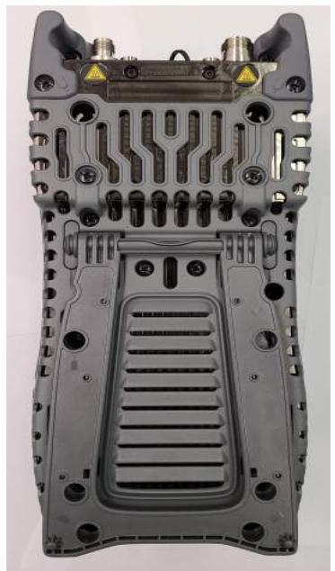
Screw Locations
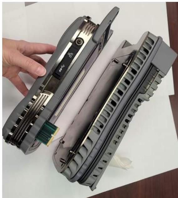
RF Module Removal
Figure B-1 RF Module Removal Process Diagrams
- Pull module straight off the back of unit to avoid damaging the PCB assembly.

NOTE
If module sticks to the Base, insert a screw driver where shown and gently pry until module releases (see Figure B-2).
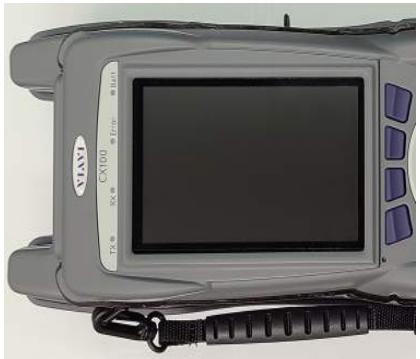
Figure B-2 Separating RF Module and Base
- Place the OneExpert Base on an ESD work surface with the display side down.

CAUTION
To avoid damaging hardware, do not place pressure against the Base PCB Assemblies.
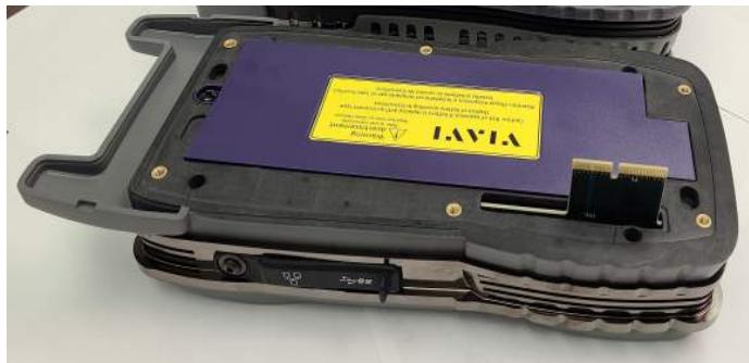
Figure B-3 Base Unit - RF Module Removed

NOTE
If the RF Module is being returned to the factory. See section 8.4, "Shipping Instructions", on page 8-2 for shipping instructions.
B.6 Installing the RF Module
The following procedure provides step by step instructions for installing the RF Application Module on the OneExpert base.

CAUTION
Modules are ESD sensitive and should only be installed, removed and/or serviced by Qualified Service Personnel.
Mise en Garde
How to Install the CX100 RF Module
- Remove the back cover from the Base.
- Install the RF Module to the Base by aligning the parts and feeding the backplane connector on the Base through the connector opening of the RF Module. Verify the RF Module is flush on the Base before proceeding.
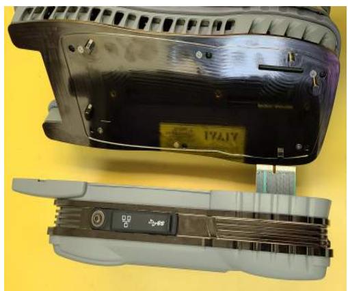
Base Cover Removal
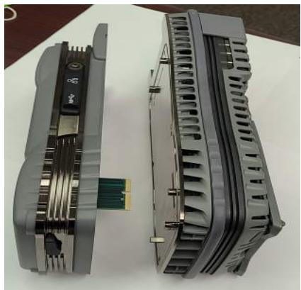
Module and Base Alignment
Figure B-4 CX100 RF Module Installation Diagram
- Firmly press the RF Module together with the Base.
- Install 6 screws securing the RF Module to the Base (Figure B-1). Torque screws to 6 in-lbs.

CAUTION
Do not over tighten the screws, doing so may crack the device's cover.
B.7 Removing the Battery
- Remove the RF Module. See section B.5, "Removing the RF Module", on page B-4.
- Loosen the screw that secures the battery cover (Figure B-5).
- Remove the cover to expose the battery.
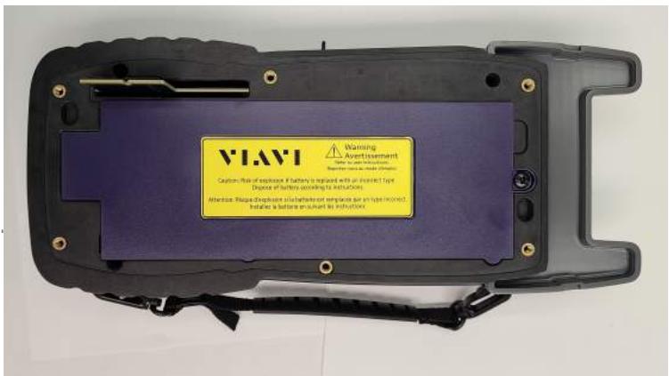
Figure B-5 Battery Cover Screw Location
- Push tab on battery cable connector clip to release and pull cable away from connector. Remove battery from the device.
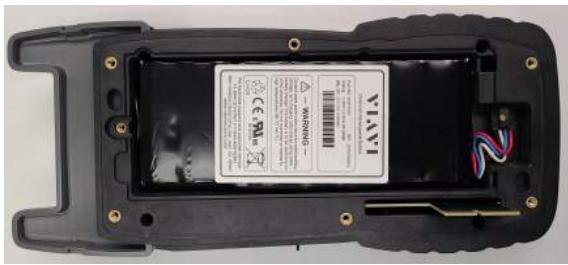
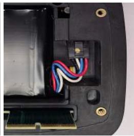
Figure B-6 Battery Cables and Release Clip
B.8 Installing the Battery
- Insert the new battery in the battery compartment.

CAUTION
When installing the new battery, use care to ensure wires are inside the compartment as shown in Figure B-6. Damage may occur if wires become pinched when installing the cover.
-
Replace Battery Cover. Reinstall the battery door and tighten the screw. Refer to Figure B-5.
-
Install the RF Module. See section B.6, "Installing the RF Module", on page B-6.
- The replacement battery is shipped in a partially charged state. The battery should be fully charged before using the device. See section 8.1, "Recharging the Battery", on page 8-2 for battery recharging instructions.
DTF Cable DB - Cable Values
This appendix lists the pre-defined cables that are found in the DTF Cable Database (DB) and each cable's parameters.
Table C-1 RG-115A Cable Values
| Parameter | Value |
| Velocity | 0.70 |
| Loss | 5.2 dB/100ft |
Table C-2 RG-142B Cable Values
| Parameter | Value |
| Velocity | 0.70 |
| Loss | 8.9 dB/100ft |
Table C-3 RG-174 Cable Values
| Parameter | Value |
| Velocity | 0.66 |
| Loss | 19.1 dB/100ft |
Table C-4 RG-213 Cable Values
| Parameter | Value |
| Velocity | 0.66 |
| Loss | 4.9 dB/100ft |
Table C-5 RG-214 Cable Values
| Parameter | Value |
| Velocity | 0.66 |
| Loss | 4.9 dB/100ft |
Table C-6 RG-223 Cable Values
| Parameter | Value |
| Velocity | 0.66 |
| Loss | 9.2 dB/100ft |
Table C-7 RG-400 Cable Values
| Parameter | Value |
| Velocity | 0.66 |
| Loss | 10.1 dB/100ft |
Table C-8 RG-55 Cable Values
| Parameter | Value |
| Velocity | 0.66 |
| Loss | 9.2 dB/100ft |
Table C-9 RG-55A Cable Values
| Parameter | Value |
| Velocity | 0.66 |
| Loss | 9.2 dB/100ft |
Table C-10 RG-55B Cable Values
| Parameter | Value |
| Velocity | 0.66 |
| Loss | 9.2 dB/100ft |
Table C-11 RG-58 Cable Values
| Parameter | Value |
| Velocity | 0.66 |
| Loss | 10.6 dB/100ft |
Table C-12 RG-58A Cable Values
| Parameter | Value |
| Velocity | 0.66 |
| Loss | 10.6 dB/100ft |
Table C-13 RG-58B Cable Values
| Parameter | Value |
| Velocity | 0.66 |
| Loss | 10.6 dB/100ft |
Table C-14 RG-58C Cable Values
| Parameter | Value |
| Velocity | 0.66 |
| Loss | 10.6 dB/100ft |
Table C-15 RG-58foam Cable Values
| Parameter | Value |
| Velocity | 0.79 |
| Loss | 10.6 dB/100ft |
Table C-16 RG-8 Cable Values
| Parameter | Value |
| Velocity | 0.66 |
| Loss | 4.9 dB/100ft |
Table C-17 RG-8A Cable Values
| Parameter | Value |
| Velocity | 0.66 |
| Loss | 4.9 dB/100ft |
Table C-18 RG-8foam Cable Values
| Parameter | Value |
| Velocity | 0.80 |
| Loss | 4.9 dB/100ft |
Table C-19 USER Cable Values
| Parameter | Value |
| Velocity | 0.75 |
| Loss | 8.7 dB/100ft |
Keyboard Mapping
This appendix shows the keyboard mapping of computer function keys to the corresponding CX100 keypad buttons. Some of the CX100's buttons and keypads have been mapped to function keys that can be found on a computer keyboard.
Table D-1 shows the keyboard mapping of computer function keys to the corresponding CX100 keypad buttons.
Table D-1 Computer to CX100 Keyboard Mapping
| Computer Keyboard | CX100 Keypad/Button |
| F1 through F4 | Correspond to the device system keys |
| F5 | Home |
| F6 | Utility Tray |
| Escape | Cancel |
| Enter | OK |
| Up, Down, Left, Right Arrows | Used to navigate menu contents. |
This page intentionally left blank.
Glossary
A A2D—Analog to Digital
ACLR - Adjacent Channel Leakage Power Ratio
AM — Amplitude Modulation
AF — Audio Frequency
ANT — Antenna
B-C BER—Bit Error Rate
BPF - Band Pass Filter
bps — bits per second
BW—Bandwidth
CW — Carrier Waveform
D D2A — Digital to Analog
DST — Daylight Savings Time
DTF — Distance to Fault
DUT - Device Under Test
E - G Ethernet TE — Ethernet Throughput Efficiency
EVM — Error Vector Magnitude
Ext - External
FIR — Finite Impulse Response
FM - Frequency Modulation
GEN - Generator
GHZ — Gigahertz
GPS - Global Positioning Satellite
GUI/UI — Graphic User Interface/User Interface
H-K HZ-Hertz
I/O — Input/Output
kbps — kilo bits per second
kHz — kilohertz
L LAN - Local Area Network
LCD — Liquid Crystal Display
LED — Light Emitting Diode
LIT - Line Item Test
LPF — Low Pass Filter
LSB — Lower Sideband
LRU - Line Replaceable Unit
M mA-milliampere
MHz — Megahertz
mHz — millihertz
Mod — Modulation
mW - milliwatt
N - R NRZ - Non-return to Zero
NTP — Network Time Protocol
OBW — Occupied Bandwidth
UOM - unit of measurement
PM — Phase Modulation
RA/RMA — Return Authorization/Return Material Authorization
RBW — Resolution Bandwidth
Ref — Reference
RMS — Root Mean Square
Rx - Receive
S - T SCA — Software Communications Architecture
Spec - Specifications
SSB — Single Sideband
SWR - Standing Wave Ratio
TAC — Technical Assistance Center for customer support
TPS - Test Program Set
T/R — Transmit/Receive for (Duplex Connector)
Tx—Transmit
U-Z
USB — Universal Serial Bus
USB - Upper Sideband
UUT - Unit Under Test
Vrms — Volts Root Mean Square
VSWR — Voltage Standing Wave Ratio
W-Watt
CX100 ComXpert Handheld Radio Test Set Operation Manual
22144015 Rev 002
Part of CD 22144014
August 2023
English
VIAVI Solutions
North America: 1.844.GO VIAVI / 1.844.468.4284
Latin America +52 55 5543 6644
EMEA +49 7121 862273
APAC +1 512 201 6534
All Other Regions: viavisolutions.com/contacts