FSCC60PW2 - Solar charge controller Furrion - Free user manual and instructions
Find the device manual for free FSCC60PW2 Furrion in PDF.
Document temporarily unavailable
The manual is currently being transferred to our new server. It will be accessible again in a few hours. Thank you for your patience.
| Product Type | MPPT Solar Charge Controller |
| Brand | Furrion |
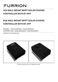
| Model | FSCC60PW2 |
| System Nominal Voltage | 12 V / 24 V |
| Maximum MPPT Charge Current | 60 A |
| Maximum Input PV Power | 750 W (12 V) / 1500 W (24 V) |
| Maximum PV Open Circuit Voltage | 95 V (25°C) / 100 V (-40°C) |
| MPPT Tracking Efficiency | 99 % |
| Maximum Conversion Efficiency | 98 % |
| Compatible Battery Types | Gel, AGM, Flooded, Lithium |
| Charge Mode | 4 stages: MPPT, Boost, Float, Equalization |
| Bluetooth Communication | Built-in, Furrion Solar App |
| Display | LCD screen and LED indicators |
| Auxiliary Load Terminals | Yes, rated current 30 A |
| Protections | Overcurrent, short circuit, reverse polarity, overheat, excessive discharge |
| Dimensions (L x H x D) | 215 x 263 x 97 mm |
| Net Weight | 2.7 kg |
| Operating Temperature Range | -20°C to 55°C |
| Protection Rating | IP32 |
| Certifications | UL 1741, CSA 22.2 No. 107.1, FCC Part 15 |
| Grounding | Common negative type, M6 lug |
| Standby Power Consumption | ≤ 14 mA |
Frequently Asked Questions - FSCC60PW2 Furrion
User questions about FSCC60PW2 Furrion
0 question about this device. Answer the ones you know or ask your own.
Ask a new question about this device
Download the instructions for your Solar charge controller in PDF format for free! Find your manual FSCC60PW2 - Furrion and take your electronic device back in hand. On this page are published all the documents necessary for the use of your device. FSCC60PW2 by Furrion.