XL-95P - Portable radio L3Harris - Free user manual and instructions
Find the device manual for free XL-95P L3Harris in PDF.
| Product type | Professional handheld radio (professional use only) |
| Brand | L3Harris |
| Model | XL-95P |
| Frequency bands | VHF (136-174 MHz), UHF (378-522 MHz), 700/800 MHz (763-870 MHz) |
| Power supply | Rechargeable battery (type not specified, estimated Li-Ion) |
| Weight (estimated) | Approximately 300 g (with battery) |
| Dimensions (estimated) | Approximately 13 x 6 x 3 cm |
| Transmit power | High and low power (selectable) |
| Duty cycle | Max 50% transmission (do not transmit more than half the time) |
| Body safety distance | At least 1.2 cm from the body, 2.5 cm from the face during transmission |
| Authorized accessories | L3Harris approved antennas, batteries, belt clips, speakers/microphones |
| Maintenance and cleaning | Clean with a damp cloth; do not use solvents; keep antenna in good condition |
| Spare parts and repairability | Antennas, batteries, chargers, microphones/speakers available; repair by qualified technician |
| RF safety | Complies with FCC and Industry Canada; use only low power if possible; do not use without antenna |
| Hazardous environments | Do not use in explosive atmospheres, blasting areas, aircraft (unless authorized) |
| Certifications | FCC Part 15, Industry Canada (CNR) |
Frequently Asked Questions - XL-95P L3Harris
User questions about XL-95P L3Harris
0 question about this device. Answer the ones you know or ask your own.
Ask a new question about this device
Download the instructions for your Portable radio in PDF format for free! Find your manual XL-95P - L3Harris and take your electronic device back in hand. On this page are published all the documents necessary for the use of your device. XL-95P by L3Harris.
USER MANUAL XL-95P L3Harris
XL Connect Series Portable Radios
MANUAL REVISION HISTORY
| REV. | DATE | REASON FOR CHANGE |
| - | Aug/21 | Initial release. |
| A | Oct/22 | Updated Options and Accessories table and added procedure for installing and removing the belt clip and D-ring. Added UHF and VHF. |
CREDITS
L3Harris, Harris, Unity, VIDA, EDACS, NetworkFirst, and OpenSky are registered trademarks of L3Harris Technologies.
Bluetooth is a registered trademark of Bluetooth SIG, Inc.
Motorola is a registered trademark of Motorola, Inc.
AMBE is a registered trademark and IMBE, AMBE+, and AMBE+2 are trademarks of Digital Voice Systems, Inc.
Wi-Fi is a registered trademark of Wi-Fi Alliance.
All brand and product names are trademarks, registered trademarks, or service marks of their respective holders.
NOTICE!
The material contained herein is subject to U.S. export approval. No export or re-export is permitted without written approval from the U.S. Government. Rated: EAR99; in accordance with U.S. Dept. of Commerce regulations 15CFR774, Export Administration Regulations.
Information and descriptions contained herein are the property of L3Harris Technologies. Such information and descriptions may not be copied or reproduced by any means or disseminated or distributed without the express prior written permission of L3Harris Technologies, PSPC Business, 221 Jefferson Ridge Parkway, Lynchburg, VA 24501.
Repairs to this equipment should be made only by an authorized service technician or facility designated by the supplier. Any repairs, alterations or substitutions of recommended parts made by the user to this equipment not approved by the manufacturer could void the user's authority to operate the equipment in addition to the manufacturer's warranty.

This product conforms to the European Union WEEE Directive 2012/19/EU. Do not dispose of this product in a public landfill. Take it to a recycling center at the end of its life.

L3Harris products comply with the Restriction of the Use of Certain Hazardous Substances in Electrical and Electronic Equipment (RoHS) Directive.
This manual is published by L3Harris Technologies without any warranty. Improvements and changes to this manual necessitated by typographical errors, inaccuracies of current information, or improvements to programs and/or equipment, may be made by L3Harris Technologies at any time and without notice. Such changes will be incorporated into new editions of this manual. No part of this manual may be reproduced or transmitted in any form or by any means, electronic or mechanical, including photocopying and recording, for any purpose, without the express written permission of L3Harris Technologies.
Copyright © 2021-2022, L3Harris Technologies.
TABLE OF CONTENTS
Section
Page
1. REGULATORY AND SAFETY INFORMATION 8
1.1 SAFETYCONVENTIONS 8
1.2 SAFETY TRAINING INFORMATION 8
1.2.1 RF Exposure Guidelines 9
1.2.2 Electromagnetic Interference/Compatibility 10
1.3 REGULATORY APPROVALS 10
1.3.1 Part 15 10
1.3.2 Industry Canada 10
1.4 OPERATING TIPS 10
1.4.1 Efficient Radio Operation 10
1.4.2 Antenna Care and Replacement 11
1.4.3 Electronic Devices 11
1.4.4 Aircraft 11
1.4.5 Electric Blasting Caps 11
1.4.6 Potentially Explosive Atmospheres 11
2. RENSEIGNEMENTS SUR LA REGLEMENTATION ET SECURITE 12
2.1 CONVENTIONS SUR LES SYMBOLES DE SECURITE 12
2.2 RENSEIGNEMENTS SUR LA FORMATION SUR LA SECURITE 12
3.3.1 Assemble the Radio 19
3.3.2 Removing the Battery 20
3.3.3 Installing the Belt Clip 20
3.3.4 Removing the Belt Clip 21
3.3.5 Installing the D-Ring 21
5.9.2 Removing the D-Ring.. 21
3.4 UNIVERSAL DEVICE CONNECTOR 22
3.5 CLEANING 22
3.6 OPTIONS AND ACCESSORIES 23
3.7 RELATED PUBLICATIONS 25
4.32.1 Conventional Failsoft (EDACS Only) 57
4.32.2 Failsoft (P25 Trunked) 57
4.33.1 Declaring an Emergency Call 58
4.33.2 Receiving an Emergency Call 58
4.33.3 Stealth Emergency 59
4.34 MDC-1200 (ANALOG CONVENTIONAL ONLY) 59
4.34.1 Normal PTT Operation 59
4.34.2 MDC PTT ID Receive Handling 59
4.34.3 Emergency Declaration 60
4.35 WI-FI CLIENT SELECTION 60
4.36 STEALTH MODE 62
5. ADVANCED OPERATIONS 63
5.1 VIEW/CHANGE PERSONALITIES 63
5.1.1 View Personalities 63
5.1.2 Change Active Personality 64
5.2 SITUATIONAL AWARENESS (SA) - P25 CONVENTIONAL ONLY 65
5.3 USER-DEFINED ZONES/SYSTEMS 66
5.3.1 Command Tactical Zone 66
5.3.2 Mixed System Zone 67
5.4 CH INFO MENU 68
5.5 AUDIO SETTINGS 68
5.6 DISPLAY SETTINGS 69
5.7 GPS SETTINGS 70
5.8 POSITION INFO 71
5.9 WI-FI 71
5.10 BLUETOOTH 73
5.10.1 Enable Bluetooth.. 73
5.10.2 Pair Devices 73
5.10.3 Reconnecting to Covert Bluetooth Microphone 12082-0684-01 .75
5.10.4 Pair with the SCOTT EPIC 3 Radio Direct Interface (RDI) Voice Amplifier ....75
5.11 CLOCK SETTINGS 75
5.12 BATTERY INFO. 76
5.13 SELECT LANGUAGE 76
5.14 SET UP SCAN 77
5.14.1 Default, Priority 1, and Priority 2 Channels .77
5.14.2 Trunked/Conventional Scanning 78
5.14.3Vote Scan (Analog and P25 Conventional Only) 78
5.14.4 Edit Scan List 79
5.14.5 Set or Remove Priority 1 and Priority 2 Channels .80
5.14.6 Custom Scan Lists 81
5.14.7 Wide Area System Scan (P25 Trunked and EDACS) 82
5.14.8 Site Lock 83
5.15 RADIO STATUS .84
5.16 RADIOMESSAGE 84
5.17 RADIO TEXTLINK 85
5.17.1 RadioTextLinkMessages 85
TABLE OF CONTENTS
Section
Page
5.17.2 RadioTextLinkForms 86
5.17.3 View Received Messages.. 86
5.18 FAULTS/ALERTS 87
5.19 TONE ENCODE 88
5.20 ENCRYPTION 88
5.20.1 Zeroize Keys from Radio 88
5.20.2 Protected Keys 89
5.20.3 Global Encryption 89
5.20.4 Select Keyset 90
5.20.5 View Key List 90
5.20.6 Delete Individual Keys 91
5.20.7 OTAR Configuration 91
5.21 P25 CONVENTIONAL FALLBACK 92
5.22 EMERGENCY CHECK-IN TIMER 92
6.PROGRAMMING 94
6.1 L3HARRIS DEVICE MANAGEMENT 94
6.2 PROGRAMMING VIA RPM2 95
6.3 EDIT CHANNEL (ANALOG AND P25 CONVENTIONAL ONLY) 95
6.4 OTAP 97
6.5 PROGRAMMABLE BUTTONS AND SWITCHES 98
6.5.1 Programmable Buttons 98
6.5.2 Programmable A/B/C Switch 100
6.6 PROGRAMMABLE ICONS 101
6.6.1 Top Display 101
6.6.2 Front Display 102
7. NARROWBANDING 103
8. GLOSSARY 104
9. BASIC TROUBLESHOOTING 107
9.1 ERROR MESSAGES 107
9.2 OTAR ERRORS/INFORMATION 109
10. TECHNICAL ASSISTANCE 110
11. WARRANTY 110
APPENDIX A WI-FI PROGRAMMING 111
APPENDIX B SCBA BLUETOOTH CONFIGURATION 117
APPENDIX C CONFIGURING ENCRYPTION 119
TABLE OF CONTENTS
Section
Page
LIST OF FIGURES
Figure 3-1: Attaching the Battery 19
Figure 3-2: Remove the Battery. 20
Figure 3-3: Universal Device Connector 22
Figure 4-1: Radio Controls, Indicators, and Connectors 26
Figure 4-2: Sample Idle Front Display. 29
Figure 4-3: Using Noise Cancellation. 44
Figure 5-1: Enabling Wi-Fi 72
Figure 5-2: Wi-Fi Install Active .72
Figure A-1: Options Network Configuration 112
Figure A-2: Wi-Fi Configuration 112
Figure A-3: Service Name 112
Figure A-4: Enable Wi-Fi in RPM2 113
Figure A-5: Enable Wi-Fi Programming Mode on Radio 114
LIST OF TABLES
Table 1-1: RF Exposure Compliance Tested Distances (Worst Case Scenario)
Table 3-1: Supported Features. 17
Table 3-2: Options and Accessories .23
Table 4-1: Radio Controls, Indicators, and Connectors 27
Table 4-2: Radio Icons. 30
Table 4-3: Status Messages 31
Table 4-4: Predefined Menu Layouts 32
Table 4-5: Menu Navigation. 34
Table 4-6: Alert Tones. 36
Table 6-1: Valid Frequency Ranges. 97
Table 6-2: Programmable Button Options. 98
Table 6-3: Single-Instance Features. 100
Table 6-4: Indexed Features. 101
Table 9-1: Displayed Error Messages, Reasons, and Resolutions. 107
Table 11-1: Wi-Fi Feature Support. 115
L3Harris Technologies, Public Safety and Professional Communications (PSPC) Business continually evaluates its technical publications for completeness, technical accuracy, and organization. You can assist in this process by submitting your comments and suggestions to the following:
L3Harris Technologies, Inc.
PSPC Business
Technical Publications
221 Jefferson Ridge Parkway
Lynchburg, VA 24501
fax your comments to: 1-434-455-6851
or
e-mail us at: PSPC_TechPubs@l3harris.com
1. REGULATORY AND SAFETY INFORMATION
1.1 SAFETY CONVENTIONS
The following conventions are used throughout this manual to alert the user to general safety precautions that must be observed during all phases of operation, service, and repair of this product. Failure to comply with these precautions or with specific warning elsewhere in this manual violates safety standards of design, manufacture, and intended use of the product. L3Harris assumes no liability for the customer's failure to comply with these standards.

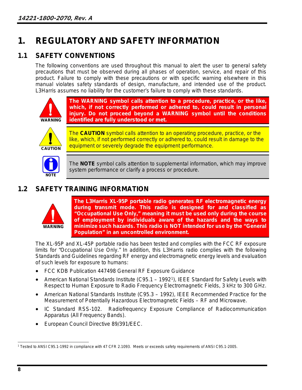
The WARNING symbol calls attention to a procedure, practice, or the like, which, if not correctly performed or adhered to, could result in personal injury. Do not proceed beyond a WARNING symbol until the conditions identified are fully understood or met.

The CAUTION symbol calls attention to an operating procedure, practice, or the like, which, if not performed correctly or adhered to, could result in damage to the equipment or severely degrade the equipment performance.

The NOTE symbol calls attention to supplemental information, which may improve system performance or clarify a process or procedure.
1.2 SAFETY TRAINING INFORMATION

The L3Harris XL-95P portable radio generates RF electromagnetic energy during transmit mode. This radio is designed for and classified as "Occupational Use Only," meaning it must be used only during the course of employment by individuals aware of the hazards and the ways to minimize such hazards. This radio is NOT intended for use by the "General Population" in an uncontrolled environment.
The XL-95P and XL-45P portable radio has been tested and complies with the FCC RF exposure limits for "Occupational Use Only." In addition, this L3Harris radio complies with the following Standards and Guidelines regarding RF energy and electromagnetic energy levels and evaluation of such levels for exposure to humans:
FCC KDB Publication 447498 General RF Exposure Guidance
American National Standards Institute (C95.1 - 1992 ^1 ), IEEE Standard for Safety Levels with Respect to Human Exposure to Radio Frequency Electromagnetic Fields, 3 kHz to 300 GHz.
- American National Standards Institute (C95.3 - 1992), IEEE Recommended Practice for the Measurement of Potentially Hazardous Electromagnetic Fields - RF and Microwave.
- IC Standard RSS-102. Radiofrequency Exposure Compliance of Radiocommunication Apparatus (All Frequency Bands).
European Council Directive 89/391/EEC.
1.2.1 RF Exposure Guidelines

To ensure that exposure to RF electromagnetic energy is within the EU/AU/FCC/IC allowable limits for occupational use, always adhere to the following guidelines:
- DO NOT operate the radio without a proper antenna attached, as this may damage the radio and may also cause the FCC RF exposure limits to be exceeded. A proper antenna is the antenna supplied with this radio by L3Harris or an antenna specifically authorized by L3Harris for use with this radio. (Refer to Table 3-2.)
- DO NOT transmit for more than 50% of total radio use time (" 50% duty cycle"). Transmitting more than 50% of the time can cause FCC RF exposure compliance requirements to be exceeded. The radio is transmitting when the "TX" indicator appears in the display. The radio will transmit by pressing the "PTT" (Push-To-Talk) button.
- ALWAYS transmit using low power when possible. In addition to conserving battery charge, low power can reduce RF exposure.
- ALWAYS use L3Harris authorized accessories (antennas, batteries, belt clips, speaker/mics, etc.). Use of unauthorized accessories may cause the FCC Occupational/Controlled Exposure RF compliance requirements to be exceeded. (Refer to Table 1-1.)
- As noted in Table 1-1, ALWAYS keep the housing of the transmitter AT LEAST 0.47 inches (1.2 cm) from the body and at least 0.98 in (2.5 cm) from the face when transmitting to ensure EU/AU/FCC/IC RF exposure compliance requirements are not exceeded. However, to provide the best sound quality to the recipients of your transmission, L3Harris recommends you hold the microphone at least 2 in (5 cm) from mouth, and slightly off to one side.
Refer to Standard EN 62311:2008.
Table 1-1: RF Exposure Compliance Tested Distances (Worst Case Scenario)
| RADIO FREQUENCY | Face2 |
| 700/800 MHz(763 - 776 MHz) | 0.98 in (2.5 cm) |
| (793 - 806 MHz) | |
| (806 - 824 MHz) | |
| (851 - 870 MHz) | |
| VHF(136 - 174 MHz) | 0.98 in (2.5 cm) |
| UHF(378 - 522 MHz) | 0.98 in (2.5 cm) |

SAR Evaluation: 1g averaged, 50% PTT Duty Factor, Occupational/Controlled Exposure.
The information in this section provides the information needed to make the user aware of RF exposure, and what to do to assure that this radio operates within the FCC RF exposure limits.
1.2.2 Electromagnetic Interference/Compatibility
During transmissions, this L3Harris radio generates RF energy that can possibly cause interference with other devices or systems. To avoid such interference, turn off the radio in areas where signs are posted to do so. DO NOT operate the transmitter in areas that are sensitive to electromagnetic radiation such as hospitals, aircraft, and blasting sites.
1.3 REGULATORY APPROVALS
Changes or modifications not expressly approved by the manufacturer could void the user's authority to operate the equipment.
1.3.1 Part 15
This device complies with Part 15 of the FCC Rules. Operation is subject to the following two conditions:
- This device may not cause harmful interference, and
- This device must accept any interference received, including interference that may cause undesired operation.
1.3.2 Industry Canada
This device complies with Industry Canada license-exempt RSS standard(s). Operation is subject to the following two conditions:
1) This device may not cause interference, and
2) This device must accept any interference, including interference that may cause undesired operation of the device.
1.4 OPERATING TIPS
Antenna location and condition are important when operating a portable radio. Operating the radio in low-lying areas or terrain, under power lines or bridges, inside of a vehicle, or in a metal framed building can severely reduce the range of the unit. Mountains can also reduce the range of the unit.
In areas where transmission or reception is poor, some improvement may be obtained by ensuring that the antenna is vertical. Moving a few yards in another direction or moving to a higher elevation may also improve communications. Vehicular operation can be aided with the use of an externally mounted antenna.
Battery condition is another important factor in the trouble-free operation of a portable radio. Always properly charge the battery.
1.4.1 Efficient Radio Operation
Keep the antenna in a vertical position when receiving or transmitting a message.

Do NOT hold onto the antenna when the radio is powered on!
1.4.2 Antenna Care and Replacement

Do not use the portable radio with a damaged or missing antenna. A minor burn may result if a damaged antenna comes into contact with the skin. Replace a damaged antenna immediately. Operating a portable radio with the antenna missing could cause personal injury, damage the radio, and may violate FCC regulations.

Use only the supplied or approved antenna. Unauthorized antennas, modifications, or attachments could cause damage to the radio unit and may violate FCC regulations. (Refer to Table 3-2.)
1.4.3 Electronic Devices

RF energy from portable radios may affect some electronic equipment. Most modern electronic equipment in cars, hospitals, homes, etc. is shielded from RF energy. However, in areas in which you are instructed to turn off two-way radio equipment, always observe the rules. If in doubt, turn it off!
1.4.4 Aircraft

Always turn off a portable radio before boarding any aircraft!
Use it on the ground only with crew permission.
DO NOT use while in-flight!!
1.4.5 Electric Blasting Caps

To prevent accidental detonation of electric blasting caps, DO NOT use two-way radios within 1000 feet of blasting operations. Always obey the "Turn Off Two-Way Radios" signs posted where electric blasting caps are being used (OSHA Standard: 1926.900).
1.4.6 Potentially Explosive Atmospheres

Areas with potentially explosive atmospheres are often, but not always, clearly marked. These may be fueling areas, such as gas stations, fuel or chemical transfer or storage facilities, and areas where the air contains chemicals or particles, such as grain, dust, or metal powders.
Sparks in such areas could cause an explosion or fire resulting in bodily injury or even death.
Turn off two-way radios when in any area with a potentially explosive atmosphere. It is rare, but possible that a radio or its accessories could generate sparks.
2. RENSEIGNEMENTS SUR LA RÉGLEMENTATION ET SÉCURITÉ
2.1 CONVENTIONS SUR LES SYMBOLES DE SECURITE
The XL-95P is a dual-band portable radio that provides advanced connectivity that first responders require while addressing evolving voice and data communications. The XL-45P is a dual-band portable radio that provides a reduced set of features. See Table 3-1 for a list features supported by both radios. They meet MIL-STD-810G for durability and are certified to more stringent MIL-STD parameters for contamination by fluids and explosive atmospheres.

ISED restricts 5150-5250 MHz to indoor use only.
Radio features include:
- Extremely Rugged - Exceeds the standards of other radios on the market.
- Single-key DES Encryption – Provides basic secure communications without having to buy the complete encryption option.
- Instant Recall of Received Audio - Allows user to replay the last transmission received to avoid unnecessary repetition.
Active Noise Cancellation - With two internal microphones to transmit intelligible audio from users in loud environments.
Built-in GPS - For location reporting and rapid response for emergencies. - Integrated Bluetooth® – For wireless interface to selected accessories.
Wi-Fi Connectivity - Permits simple and easy radio software and personality updates. - Covert Mode - Allows users to quickly configure the radio for operation in a covert environment.
- Fully Programmable Keypad - Each key can be programmed to a variety of functions.
- Three-position switch - Provides added configuration flexibility.
- Unique User Interface - Tools specially designed by first responders make radio operation simple and intuitive with an easy-to-read multi-color front display.
Refer to Table 3-2 for the list of options and accessories. Additional accessories may have been added since publication of this manual; contact L3Harris for more information.
Table 3-1: Supported Features
| FEATURE DESCRIPTION | XL-95P | XL-45P |
| Conventional Priority Scan | Standard | Standard |
| EDACS 3-Site System Scan | Standard | Not Supported |
| EDACS Group Scan | Standard | Not Supported |
| EDACS Priority System Scan | Standard | Not Supported |
| EDACS/P25 System Scan: ProScan/ProSound/Wide Area Scan | Standard | Standard (P25 Only) |
| EDACS/P25 Dynamic Regroup | Standard | Standard (P25 Only) |
| EDACS/P25 Emergency | Standard | Standard (P25 Only) |
| Type 99 Encode and Decode | Standard | Standard |
| Conventional Emergency | Standard | Standard |
| Digital Voice | Standard | Standard |
| DES Encryption (64-Bit) | Optional | Not Supported |
| EDACS/P25 Mobile Data | Optional | Optional (P25 Only) |
| EDACS/P25 Status (RSM) and Message (RTT) | Included with Operational Mode | Included with Operational Mode |
| EDACS Security Key/P25 Personality Lock | Included with Operational Mode | Included with Operational Mode |
| ProFile™ | Optional | Optional |
| Narrowband | Standard | Standard |
| ProVoice | Optional | Not Supported |
| FIPS 140-2 | Optional | Not Supported |
| P25 Common Air Interface (CAI) | Standard | Standard |
| Direct Frequency Entry | Included with P25 Phase 1 | Included with P25 Phase 1 |
| P25 Over-The-Air Rekeying (P25 OTAR) | Optional | Not Supported |
| EDACS/P25 AES Encryption (256-Bit) | Optional | Optional (P25 Only) |
| Radio TextLink | Optional | Optional |
| P25 Trunking | Optional | Standard |
| Conventional Vote Scan | Optional | Optional |
| P25 Phase II (TDMA) | Optional | Optional |
| GPS | Standard | Optional |
| Bluetooth | Standard | Standard |
| Wideband Disable | Standard | Standard |
| MDC-1200 Signaling | Standard | Standard |
| Single-Key DES Encryption | Optional | Optional |
| Wi-Fi | Standard | Optional |
| Link Layer Authentication | Optional | Optional |
| eData | Optional | Optional |
| In-Band GPS | Optional | Optional |
| Encryption Lite (Arc4) | Optional | Optional |
| Single Key AES | Optional | Not Supported |
3.2 STORAGE GUIDELINES
Store your radio and batteries in a clean, cool [not exceeding 86^ (+30^)] , dry, and ventilated storage area.
3.3 BASIC SETUP
3.3.1 Assemble the Radio

Only use L3Harris chargers approved for the battery chemistry. Injury could occur from improper charger use.

Do not over-tighten the antenna as damage could result. Torque should not exceed 20 in lbs. This torque is measured at a grip point one inch above the antenna's base.

Fully charge the battery before first use. Due to government regulations, batteries ship in a discharged state and may require up to two (2) minutes in a charger for successful initialization. During initialization, the charger does not show any charge indication. After this initialization period, charging resumes normally.
- Make sure batteries are charged per the manual supplied with the charger.
- Align the tabs at each side on the bottom of the battery with the slots at the bottom of the battery cavity ①.
- Push the top of the battery ② down until the latches click to attach the battery to the radio.
- Tug gently to verify that the latches are secure and the battery is properly attached to the radio.

Figure 3-1: Attaching the Battery
3.3.2 Removing the Battery
- Press or pull both latches on either side of the battery ① toward the bottom of the radio simultaneously.
- Pull the battery ② away from the radio.
- Remove the battery pack from the radio.
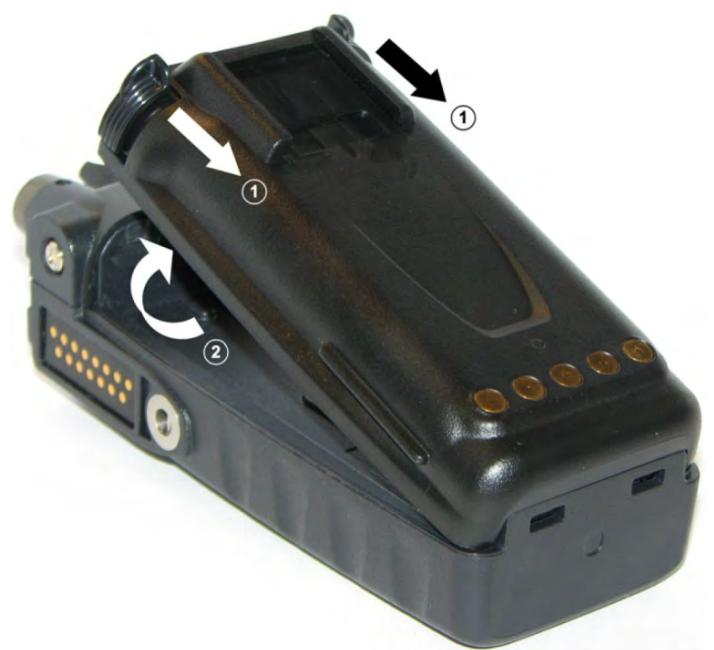
Figure 3-2: Remove the Battery
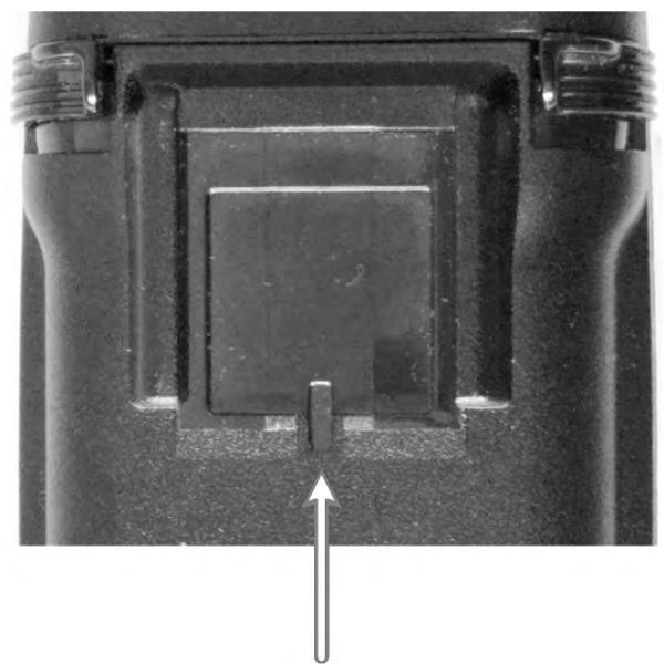
3.3.3 Installing the Belt Clip
While pressing down on the belt clip, slide into the slot on the back of the battery until it clicks into place.

3.3.4 Removing the Belt Clip
- Press down on the belt clip.
- Using a small flat head screw driver or equivalent, carefully pry up on the clip spring. There is a small groove in the battery that allows the flat blade to fit under the clip.
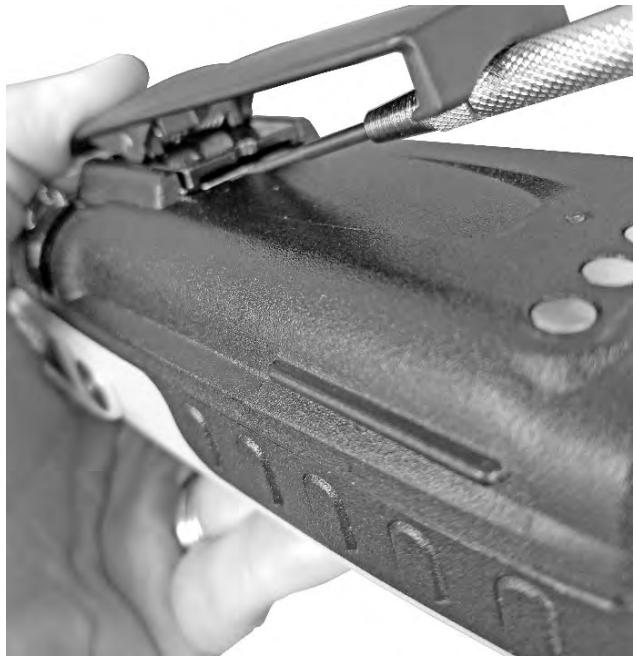
- Slide the belt clip out of the slot on the battery.
3.3.5 Installing the D-Ring
Slide the D-Ring into the slot on the back of the battery until it clicks into place.
5.9.2 Removing the D-Ring
- Using a small flat head screw driver or equivalent, carefully pry up on the clip spring as shown below. There is a small groove in the battery that allows the flat blade to fit under the clip.
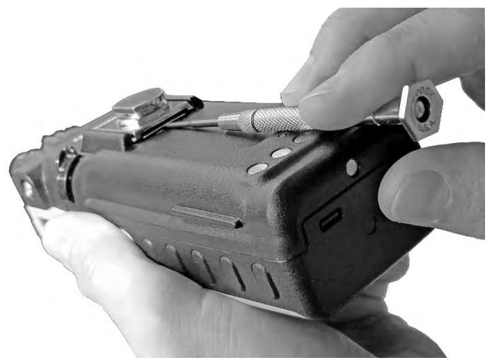

- Slide the D-Ring out of the slot on the battery.
3.4 UNIVERSAL DEVICE CONNECTOR
The Universal Device Connector (UDC) provides connections for external accessories such as a headset, a speaker-microphone, audio test box, audio test cables, and programming cables. The UDC is located on the right side of the radio, opposite the PTT Button. The UDC facilitates programming and testing the radio. The UDC pins perform different functions depending on the accessory attached to the UDC.

Figure 3-3: Universal Device Connector
3.5 CLEANING
Keep the exterior of the radio, battery, antenna, and radio accessories clean.
Periodically clean using the following procedures:
- To remove dust and dirt, clean using damp clean cloth (warm water and mild detergent soap or Simple Green).
- Follow by wiping with damp (warm water) clean cloth. Wipe dry with clean cloth.
- Remove the battery and wipe the battery and radio contacts using a soft dry cloth to remove dirt or grease. This will ensure efficient power transfer from the battery to the radio.
- Remove any accessories and clean the UDC contacts using a clean dry cloth. When the UDC is not in use, cover the connector with the protective dust cap to prevent the build-up of dust or water particles.
- If the radio is used in a harsh environment (such as driving rain, salt fog, etc.), it may be necessary to periodically dry and clean the battery and radio contacts with a soft dry cloth or soft-bristle non-metallic brush.
For more rigorous cleaning, use the following procedure:

CAUTION
Do not use chemical cleaners, spray, or petroleum-based products. They may damage the radio housing. L3Harris recommends Calla 1452 or equivalent.
- Apply the cleaning solution to a clean damp cloth and clean the radio.

NOTE
Do not spray cleaning solution directly on radio. To clean the radio in the speaker and microphone areas, carefully wipe these areas but prevent the cleaning solution from entering the speaker or microphone openings.
- Wipe off the radio with clean damp cloth using mild warm soapy water.
- Follow up by wiping off the radio with clean damp cloth using warm water only.
- Wipe dry with clean cloth.
3.6 OPTIONS AND ACCESSORIES
Only use L3Harris approved accessories. Refer to L3Harris' Product and Services catalog for the complete list of options and accessories available. Contact L3Harris for requirements not contained in this list:

CAUTION
Always use the correct options and accessories (battery, antenna, speaker/mic, etc.) for the radio. Immersion rated options must be used with an immersion rated radio. Refer to Table 3-2.
Table 3-2: Options and Accessories
| DESCRIPTION | PART NUMBER |
| ANTENNAS | |
| Antenna, Whip, 1/2 Wave 762-870 MHz | 14035-4440-01 |
| Antenna, Whip, 1/4 Wave, 762-870 MHz | 14035-4440-02 |
| Antenna, 378-430 MHz, Whip | KRE1011223/10 |
| Antenna, 378-403 MHz, Helical | KRE1011219/9 |
| Antenna, 403-430 MHz, Helical | KRE1011219/10 |
| Antenna, 440-512 MHz, Whip | KRE1011223/12 |
| Antenna, 440-494 MHz, Helical | KRE1011219/12 |
| Antenna, 470-512 MHz, Helical | KRE1011219/14 |
| Antenna, 150-174 MHz,Helical,Wideband | KRE1011219/21 |
| Antenna, 150-162 MHz, Helical | KRE1011219/2 |
| Antenna, 136-151 MHz, Helical | KRE1011219/1 |
| Antenna, Flex, Helical, 136-870 MHz | 14035-4000-01 |
| Antenna, Whip,Dual-Band,UHF/700/800 MHz | 14035-4420-01 |
| BATTERIES | |
| Lithium-polymer battery, immersible, non-IS (7.4V, 3600 mAh) | BT-023436-001 |
| AA Alkaline Clam Shell Battery Case | 14002-0199-01 |
| Li-ion Battery, 3100 mAH | 14002-0214-01 |
| Li-Ion Battery, 3100 mAH, ALT | 14002-0214-01 |
| CHARGERS | |
| Charger, Six-Bay | 14002-0600-06 |
| Charger, Single | 14002-0500-01 |
| Charger, Six-Bay, Li Battery | 14035-1800-02 |
| Wall Mount Kit, 6-Bay Li-Ion/Poly Charger | 12082-0315-01 |
| AUDIO ACCESSORIES | |
| Speaker Mic without Antenna (cc) provision | MC-023933-001 |
| Rugged Speaker Mic, Antenna, Straight, SBR | MC-011617-602 |
| Earphone for Speaker Mic | LS103239V1 |
| Earphone for Speaker Mic, right angle jack | LS103239V2 |
| Speaker Mic, Wireless, Bluetooth, Advanced | 12082-0800-02 |
| Speaker Mic, Wireless, Bluetooth, Advanced, ANZ | 12082-0800-03 |
| Ruggedized Speaker Mic-Coil Cord | MC-011617-601 |
| Standard Speaker Mic - Non-Ant | MC-011617-701 |
| Rugged Speaker Mic, Coiled Cord, Hi-Visibility | MC-011617-606 |
| Speaker Mic, Straight Cord, 25.6in, Antenna | MC-011617-703 |
| Speaker Mic, Antenna, Straight, 18in | MC-011617-718 |
| Speaker Mic, Antenna, Straight, 30in | MC-011617-730 |
| Speaker Mic, Rugged, Coiled, Hirose Port | MC-011617-611 |
| DROP SHIP AUDIO ACCESSORIES | |
| Earphone Kit, Black | EA-009580-001 |
| Earphone Kit, Beige | EA-009580-002 |
| 2-Wire Kit, Palm Mic, Black | EA-009580-003 |
| 2-Wire Kit, Palm Mic, Beige | EA-009580-004 |
| 3-Wire Kit, Mini-Lapel Mic, Black | EA-009580-005 |
| 3-Wire Kit, Mini-Lapel Mic, Beige | EA-009580-006 |
| Explorer Headset with PTT | EA-009580-007 |
| Lightweight Headset Single Speaker with PTT | EA-009580-008 |
| Breeze Headset with PTT | EA-009580-009 |
| Headset, Heavy Duty, N/C Behind-the-Head, with PTT | EA-009580-010 |
| Ranger Headset with PTT | EA-009580-011 |
| Skull Mic with Body PTT and Earcup | EA-009580-012 |
| Headset, Heavy Duty, N/C Over-the-Head, with PTT | EA-009580-013 |
| Throat Mic with Acoustic Tube and Body PTT | EA-009580-014 |
| Throat Mic with Acoustic Tube, Body PTT, and Ring PTT | EA-009580-015 |
| Breeze Headset with PTT and Pigtail Jack | EA-009580-016 |
| Hurricane Headset with PTT | EA-009580-017 |
| Hurricane Headset with PTT and Pigtail Jack | EA-009580-018 |
| CARRYING CASE ACCESSORIES | |
| Belt Loop, Leather, Premium | 14002-0218-01 |
| Case, Leather, Premium, XL-95, Belt Loop | 14002-0215-01 |
| Case, Leather, Premium, XL-95, Shoulder Strip | 14002-0215-02 |
| Case, Nylon, Tactical Green, Molle Strip | 14002-0217-01 |
| Black Nylon Case with Belt Loop Kit | 14011-0012-01 contains: 14011-0011-01 CC-014527 |
| Orange Nylon Case with Belt Loop Kit | 14011-0012-02 contains: 14011-0011-02 CC-014527 |
| Leather Case with Belt Loop Kit | 14011-0012-03 contains: 14011-0011-03 KRY 1011 608/2 CC-014527 |
| Leather Case with Shoulder Strip Kit | 14011-0012-04 contains: 14011-0011-04 KRY 1011 608/2 CC-014524-001 |
| Short Leather Retaining Strip (use with Shoulder Strip application) | CC-014524-002 |
| Metal Belt Clip | CC23894 |
| Strap Holder, "T" | KRY 101 1656/1 |
| Belt Loop, Leather with Swivel | KRY 1011 609/1 FM-017262-001 |
3.7 RELATED PUBLICATIONS
The following publications contain additional information about the radio and related products:
| MANUAL NUMBER | DESCRIPTION |
| 14221-1800-2080 | Product Safety Manual |
| 14221-1800-1020 | Radio Quick Guide |
| 14221-1800-5040 | Maintenance Manual |
| MM1000019423 | Key Manager and Key Admin Overview and Operation Manual |
| MM1000019424 | Key Manager and Key Loader Overview and Operation Manual |
| 14221-7200-6110 | Voice Annunciation Feature Manual |
| 14221-2100-3000 | Advanced Access Control (AAC)/Radio Personality Manager (RPM) Overview Manual |
| 14221-1100-8170 | Radio Personality Manager 2 (RPM2) Software Release Notes |
| 14221-1100-2060 | RPM2 User's Manual |
| 14221-1800-8010 | XLP Radio Software Release Notes |
| 14221-2100-2010 | L3Harris Device Management User's Manual |
| 14221-2100-8030 | L3Harris Device Management Software Release Notes |
The product safety manual and the quick guide are included with the radio equipment package when the radio ships from the factory. All publications listed above are available at https://premier.pspc.harris.com/ with a Tech Link login.
4. BASIC OPERATION
4.1 RADIO CONTROLS, INDICATORS, AND CONNECTORS
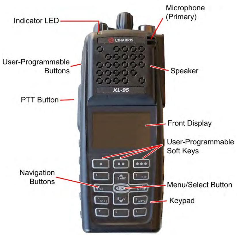
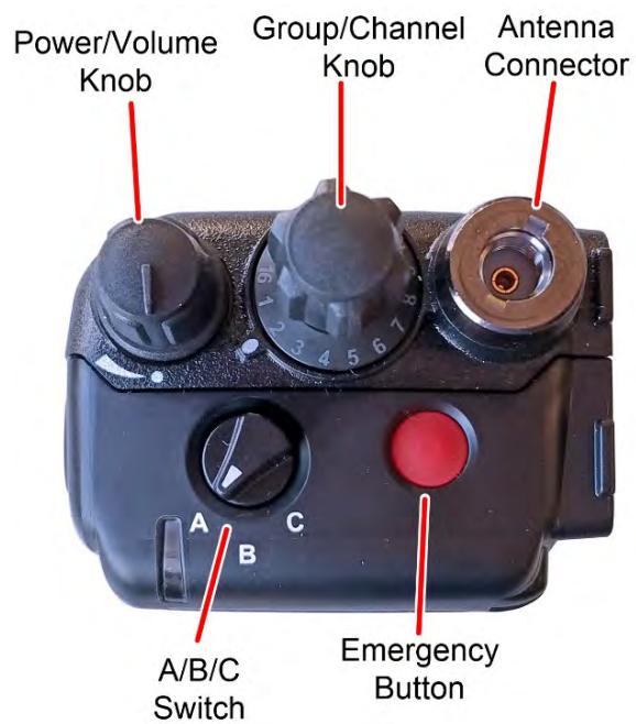
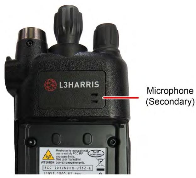
Figure 4-1: Radio Controls, Indicators, and Connectors

NOTE
Table 4-1 describes the default functions of buttons, knobs, and controls. Most can be programmed for different functions; see Section 6.5 for more information.
Table 4-1: Radio Controls, Indicators, and Connectors
| CONTROL/INDICATOR | FUNCTION |
| Power/Volume Knob | Turn clockwise to power on radio and increase volume of audio heard from speaker. Minimum volume levels may be programmed into the radio to prevent missed calls due to a low volume setting. |
| Group/Channel Knob | Selects groups/channels. |
| Microphone (Secondary) | When noise cancellation is enabled, the secondary and primary microphone are used together to form a dual microphone system. Noise cancellation improves the quality of transmitted voice. When noise cancellation is disabled, only the primary microphone is used. See Section 4.16 for detailed information on using noise cancellation. |
| A/B/C Switch | User-programmable switch (see Section 6.5.2). By default, selects one of three channel banks (see Section 4.11). |
| User-Programmable Buttons | Used to select a commonly used function as an alternative to navigating menus. This is configured via programming using Radio Personality Manager 2 (RPM2). See Section 6.5.1 for the options that can be programmed to these buttons. |
| Push-To-Talk (PTT) Button | Press to transmit. Make sure Push-To-Talk (PTT) is enabled (Section 5.5). |
| Battery | Battery - Refer to Section 3.3 for battery connection and removal. |
| Antenna Connector | Antenna connector. |
| Emergency Button | Used to place radio in emergency mode (see Section 4.32). This button can be disabled via programming using RPM2. In addition, this button can be used in conjunction with a User-Programmable Button to clear emergencies if configured to do so. |
| Indicator Light Emitting Diode (LED) | Indicates radio status: • Red = actively transmitting. • Green = actively receiving. • Orange = actively transmitting encrypted. |
| Speaker | Radio speaker which can be muted (Section 5.5). Adjust volume using the Power/Volume knob. |
| Microphone (Primary) | When noise cancellation is enabled, the primary and secondary microphones are used together to form a dual microphone system. Noise cancellation improves the quality of transmitted voice. When noise cancellation is disabled, only the primary microphone is used. See Section 4.7 for detailed information on using noise cancellation. |
| Front Display | Front display shows complete status and radio menus. |
| User-Programmable Soft Keys | User-programmable dynamic keys that have their current function labeled on the radio display directly above each button. See Section 6.5.1 for the options that can be programmed to these buttons. |
| Menu/Select Button | From the Main Display, press this button to access the menu. Also, selects highlighted menu items. |
| Navigation Buttons | Navigates menu items. In addition: • Press the left navigation button while on the idle display to access Channel Information (see Section 5.4). By default, this feature is disabled by RPM2. • Press the down navigation button while on the idle display to display the functions assigned to programmable buttons (see Section 6.5). • Press the up navigation button to display Missed Call info. • Press the right navigation button to end or reject an I-Call. |
| Keypad | By default, used to enter text or numbers. Can be programmed for various functions (see Section 6.5). |
4.2 BEFORE FIRST USE
Make sure the radio has:
- Fully charged battery
- Antenna attached
- Personality and radio programmed using RPM2
- Encryption keys loaded if using encrypted channels
- Personality activated
4.3 POWER ON AND SET VOLUME
The power switch and volume control are the same knob on top of the radio (see Figure 4-1). Turn the Power/Volume Knob clockwise to power on radio and increase the volume. The radio can be programmed to play an audible tone when changing the volume.

NOTE
A minimum volume level can be programmed into the radio to prevent missed calls due to a low volume setting.

NOTE
The radio can be programmed to require the entry of a PIN to operate the radio. Check with your System Administrator if you forget your PIN. As the PIN is entered, an asterisk is displayed for each digit; the actual value is not displayed.
4.4 VIDA ID
VIDA ID provides the capability to provision the VIDA User Personality configured in the UAS to radios operating on P25 networks via a User Login. Each personality can contain up to 16 profiles and each profile can contain up to sixteen Talk Groups. Refer to Section 9.1 for a list of potential login and provisioning error messages and what to do if they occur.
4.4.1 User Login
User Login enables multiple radio users to pick a radio from a fleet pool and enter unique credentials to log into the P25 system. Upon successful login, the Alias associated with the radio user is displayed at various end points in the P25 system.
A user can login on up to three (3) devices simultaneously. For example, if the "same user" is logged into a portable radio and mobile radio, the P25 system can differentiate the subscribers while transparently displaying the alias to other users.
Login can be initiated by a menu option, a button programmed for user login, or by selecting a P25 system that requires login. To login manually:
- From the UTILITY radio menu, select USER LOGIN, or press the button programmed for User Login.
- Enter the System ID, User ID, and Password, as required.
- Select Login.
4.4.2 Provisioning
If provisioning is enabled via radio programming and the user has successfully logged in, the VIDA User Personality configured in the UAS is provisioned to the radio. When no VIDA Provisioned database is available, the radio will operate using the RPM2-programmed personality.
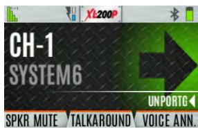
4.5 RADIO DISPLAY
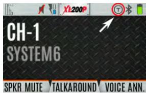
Figure 4-2 shows a sample front display while on the idle screen. The idle screen appears after power up or after exiting from the menus.
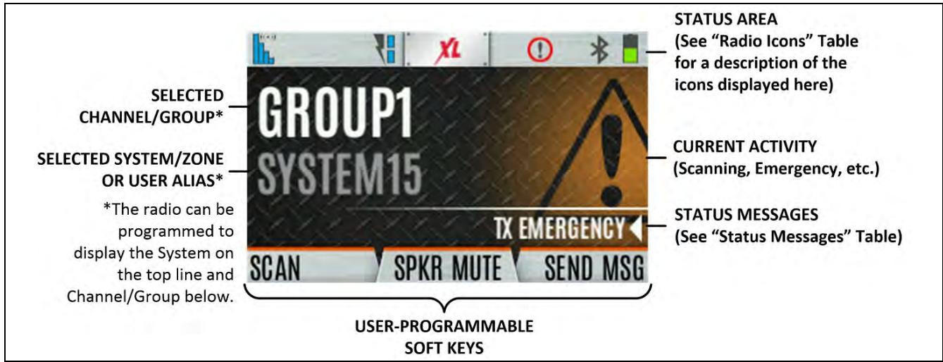
Figure 4-2: Sample Idle Front Display

NOTE
The radio can be programmed to display the User ID on the System line of the display.
Table 4-2 describes some of the icons that may be displayed by the radio. The radio menu also contains an icon glossary in the Utility Menu (see Section 4.7). Icons and their location can be customized using RPM2.
Table 4-2: Radio Icons
| ICON | DESCRIPTION | ICON | DESCRIPTION | ICON | DESCRIPTION |
| Analog Conventional System | P25 Conventional System | P25 Trunked System | |||
| EDACS System | Zone | User Defined Zone | |||
| (Blue) Trunked Signal Strength | Bluetooth Enabled | Monitor On | |||
| (Red) TX Power | (Blue) Bluetooth Connected | VDOC | |||
| (Green) Receive Signal Strength | Encryption Enabled | Receiving Data | |||
| (No Color) Channel Idle | Global Encryption | Transmitting Data | |||
| (Orange) Transmitting Encrypted | OTAR Disabled | Alert(s) Present | |||
| Battery Fully Charged | OTAR Registered | Vote Scanning | |||
| Battery Level 100% Capacity | OTAR Registering | Scanning Enabled | |||
| Battery Level 75% Capacity | OTAR Rekeying | Emergency | |||
| Battery Level 50% Capacity | Transmit Power Level High | RX Mail | |||
| Battery Level 25% Capacity | Transmit Power Level Low | Noise Cancellation Enabled | |||
| Battery Level 5% Capacity (Low Battery Audio Indicator) | RX Only | Fire Speaker Mic Attached4 | |||
| Battery Level Battery Exhausted (RX-Only State) | Speaker Muted | Nuisance Channel | |||
| Battery Charging5 | TX Disabled | Conventional Site Unregistered | |||
| Talkaround Enabled | Tones Disabled | Conventional Site Registered |
For the Fire Speaker Mic Attached icon to display, first the Noise Cancellation icon must be programmed to the radio's front display via RPM2. When you attach the Fire Speaker Microphone (FSM) to the radio and Noise Cancellation is enabled, then the Fire Speaker Mic Attached icon is displayed, replacing the Noise Cancellation icon. This indicates that Noise Cancellation is now being used from the FSM rather than the radio.
5 Not displayed when charging 14002-0214-01/14002-0214-04 batteries.
| ICON | DESCRIPTION | ICON | DESCRIPTION | ICON | DESCRIPTION |
| A! | Failsoft | PTT Disabled | T99 | Type 99 Enabled | |
| Wi-Fi Signal Strength Indicator | Wi-Fi Network in Process of Connecting | Wi-Fi Network in Process of Connecting | GPS Tracking | ||
| Wi-Fi Network Currently Connected | Add New Wi-Fi Client | Wi-Fi Clients Connected | Wi-Fi Clients Connected | ||
| A wearable Bluetooth device is attached [e.g., Self-Contained Breathing Apparatus (SCBA)] |
4.6 STATUS MESSAGES
The radio may display various radio Status Messages during operation. These messages are described in Table 4-3.
Table 4-3: Status Messages
| MESSAGE | DESCRIPTION |
| PTT DENIED | P25 Trunked and EDACS - The radio or talkgroup is not authorized to operate on the selected system and/or talkgroup. |
| CALL QUEUED | P25 Trunked and EDACS - The system has placed the call in a request queue. |
| SYSTEM BUSY | P25 Trunked and EDACS - The system is busy, no channels are currently available, the queue is full, or an individual call is being attempted to a radio that is currently transmitting. |
| SCANNING | The radio is scanning. |
| TX EMERGENCY | An emergency call is being transmitted. |
| RX EMERGENCY | An emergency call is being received. The radio displays the unit name or unit ID. |
| WIDE AREA SCAN | P25 Trunked and EDACS - The radio has entered the Wide Area Scan mode to search for a new system. |
| INVALID TALKGROUP | P25 Trunked and EDACS - The current talkgroup is not valid for the current system. This could happen if the site denies registration due to an unrecognized talkgroup ID. |
| INVALID UNIT | P25 Trunked and EDACS - The current unit is not valid for the current system. |
| REGISTERING | P25 Trunked only - Displayed when the radio is performing a registration/affiliation on a P25 trunking site. |
| CTRL CHANNEL SCAN | P25 Trunked and EDACS - The control channel is lost and the radio has entered the Control Channel Scan mode to search for the control channel (usually out of range indication). |
| BAND SCANNING | P25 Trunked - Only displayed if the system is configured for "EnhancedCC" mode of operation. When the radio cannot find a Control Channel in either the trunked frequency set or the list of discovered adjacencies, the radio can perform a full spectrum frequency scan to find a new Control Channel. |
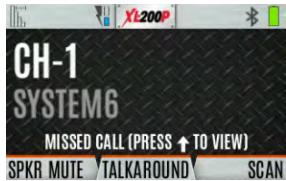
| MISSED CALL | P25 Modes and EDACS - Another user has tried to call or page this radio. The user can view who the caller was by pressing the up navigation button. |
| OTAR REKEY COMPLETE | OTAR Rekey operation completed successfully. |
| USER REGISTRATION Failed | User Login failed. Change selected system/zone or re-enter credentials. |
4.7 PREDEFINED MENU LAYOUTS
Depending on radio programming, some menu options described in this manual may not be available. The radio supports three predefined menu layouts: Full, Custom, and Restricted. Table 4-4 details what is available in each layout:

NOTE
The Custom predefined menu layout allows the administrator to customize the list of menu items that are available to the radio user. Table 4-4 lists the default settings.
Table 4-4: Predefined Menu Layouts
| MENU | FULL | CUSTOM (Default Settings) | RESTRICTED |
| Call Menu | Yes | Yes | Yes |
| Exit Emergency | Yes | Yes | Yes |
| Talkaround | Yes | Yes | Yes |
| Individual Call | Yes | Yes | Yes |
| Change Talkgroup | Yes | Yes | Yes |
| Call Alert/Page | Yes | Yes | Yes |
| Channel Guard | Yes | Yes | Yes |
| Audio Playback | Yes | Yes | No |
| Tone Encode | Yes | Yes | Yes |
| T99 | Yes | Yes | Yes |
| Emergency Timer | Yes | Yes | No |
| Active Emergency Display | Yes | Yes | Yes |
| Audio Settings | Yes | No | No |
| Display Settings | Yes | Yes | Yes |
| GPS Settings | Yes | No | No |
| Clock Settings | Yes | Yes | No |
| Bluetooth Settings | Yes | Yes | No |
| Scan Menu | Yes | Yes | Yes |
| Enable/Disable Scan | Yes | Yes | Yes |
| View Scan List | Yes | Yes | No |
| Edit Zone Scan List | Yes | No | No |
| View Custom Channels | Yes | Yes | No |
| Edit Custom Scan List | Yes | No | No |
| Custom Scan | Yes | Yes | No |
| Site Roam | Yes | Yes | No |
| Site Alias | Yes | Yes | No |
| Security Menu | Yes | Yes | Yes |
| Encryption Enable | Yes | Yes | Yes |
| Zeroize | Yes | No | No |
| Global CKR Enable | Yes | No | No |
| GCKR Key Select | Yes | No | No |
| Active Key Set | Yes | Yes | Yes |
| Key List | Yes | Yes | No |
| OTAR Enable | Yes | Yes | No |
| OTAR Rekey | Yes | Yes | Yes |
| Message Menu | Yes | Yes | Yes |
| Radio Status | Yes | Yes | No |
| Radio Message | Yes | Yes | No |
| Textlink Messages | Yes | Yes | No |
| Textlink Forms | Yes | Yes | No |
| Textlink Mailbox | Yes | Yes | No |
| Faults | Yes | Yes | Yes |
| Program Menu | Yes | Yes | No |
| Activate Plan | Yes | Yes | No |
| Activate Profile | Yes | Yes | No |
| Maintenance Menu | Yes | Yes | Yes |
| Radio Info | Yes | Yes | No |
| Battery | Yes | Yes | No |
| TCXO Tuning | Yes | No | No |
| P25 Tests | Yes | No | No |
| RSSI Display | Yes | Yes | Yes |
| Phase II Display | Yes | Yes | No |
| Feature Info | Yes | Yes | No |
| WiFi Client | Yes | Yes | No |
| WiFi Access Point | Yes | Yes | Yes |
| Change Language | Yes | No | No |
| Change PIN | Yes | Yes | Yes |
| Icon Glossary | Yes | Yes | Yes |
| User Login | Yes | Yes | Yes |
| System ID | Yes | Yes | Yes |
| Unit ID | Yes | Yes | Yes |
| Password | Yes | Yes | Yes |
| Device Management | Yes | Yes | Yes |
| Install GPP Software | Yes | Yes | Yes |
| Zone | Yes | Yes | No |
4.8 MENU
Press the Menu/Select button while on the idle display to access the menu. Press the left or right navigation buttons to scroll through the top-level menus and press the up or down navigation buttons to scroll through the sub-menus. Refer to Figure 4-1 for button location. While in a menu, press the Menu/Select button to choose, activate, or toggle the selected item; similar to an enter key. Table 4-5 provides a high-level overview of the menu layout. Menu options on your radio may vary depending on available features and radio programming.
Table 4-5: Menu Navigation
| MENUS | DESCRIPTION |
| CALL MENU: | |
| EXIT EMERGENCY MODE | Exits emergency. See Section 4.32 for more information. |
| TALKAROUND MODE | Enable/disable talkaround. See Section 4.22 for more information. |
| INDIVIDUAL CALL | Allows you to select an individual for an individual call. See Section 4.14 for more information. |
| CHANGE TLKGRP | Change the selected talkgroup. See Section 4.13. |
| PHONE CALL | Allows the user to initiate a telephone interconnect call. See Section 4.25 for more information. |
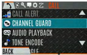
| CALL ALERT | Select a group for Call Alert transmission. See Section 4.24. |
| CHANNEL GUARD | Select the Transmit and/or Receive Channel Guard tone. See Section 4.21. |
| AUDIO PLAYBACK | Replays the last recorded call. See Section 4.27 for more information. |
| TONE ENCODE | Analog conventional only - Transmits a programmed tone sequence on the current radio system and channel. See Section 5.19 for more information. |
| T99 TOGGLE | Enable/disable T99. See Section 4.23 for more information. |
| EMERGENCY TIMER | Enable/disable the Emergency Check In Timer. See Section 5.22 for more information. |
| ACTIVE EMERG DISPLAY | Allows the radio user to see the units currently in emergency (up to 20) on the radio display. |
| SCAN MENU: | |
| START SCAN/STOP SCAN | Start or stop scan operation. See Sections 4.28 and 4.29. |
| SCAN Lists | View/Edit available scan lists. See Section 5.14. |
| ASSIGNED CUSTOM LIST | Create, View, and Edit Custom Scan Lists. See Section 5.14.6. |
| SITE ROAMING | Enable/Disable Wide Area System Scan. See Section 5.14.7. |
| SITE ALIAS | Select an available site from this list to lock the radio to; i.e., prevent the radio from roaming. This is also known as Site Lock. See Section 5.14.8 for more information. |
| SECURITY MENU: | |
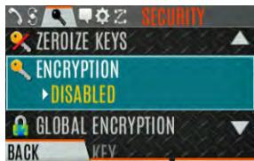
| ZEROIZE KEYS | Removes all encryption keys from the radio. See Section 5.20.1. |
| ENCRYPTION | Enable/Disable encryption. See Section 4.19. |
| GLOBAL ENCRYPTION | Enable/Disable Global Encryption. See Section 5.20.3. |
| GLOBAL KEY | Select the Global Key. Only available if Global Encryption is Enabled. See Section 5.20.3. |
| ACTIVE KEYSET | Select the Active Keyset. See Section 5.20.4. |
| KEY LIST | View available key lists. See Section 5.20.5. |
| OTAR | Enable/disable Over-the-Air Rekeying (OTAR). See Section 5.20.6. |
| OTAR REKEY | Request that the KMF updates the keys in the radio. See Section 5.20.6. |
| ZEROIZE ALL | Removes all keystores from the radio. |
| MESSAGE MENU: | |
| RADIO STATUS | Used to send a status condition to the site without making a voice call. See Section 5.14.8. |
| RADIOMESSAGE | Used to send a message to the site without making a voice call. See Section 5.16. |
| TEXTLINK MESSAGES | Allows the user to send a Radio TextLink message. See Section 5.17. |
| TEXTLINK FORMS | Allows the user to send a Radio TextLink form. See Section 5.17. |
| TEXTLINK MAILBOX | Contains received Radio TextLink messages. See Section 5.17. |
| FAULTS/ALERTS | Displays radio faults and alerts. See Section 5.18. |
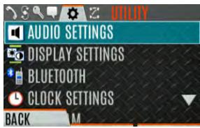
| UTILITY MENU: | |
| AUDIO SETTINGS:· SPEAKER (MUTE/UNMUTE)· NOISE CANCELLATION· PTT· TONES· KEYPAD TONES· VOICE ANNUNCIAIATION | Mute or unmute the speaker audio. Enable or disable Noise Cancellation. See Section 4.16. Enable or disable Push-To-Talk (PTT). Disable PTT to prevent accidental keying, such as when radio is in the holster or you are getting into a car. Enable or disable radio side tones. Enable or disable tones that sound when the radio's keypad buttons are pressed. Enable or disable Voice Annunciation. |
| DISPLAY SETTINGS: • COLOR SCHEME • INDICATOR LED • FRONT BACKLIGHT • FRONT BRIGHTNESS • FRONT TIMEOUT • FRONT DISPLAY OFF | Press the Menu/Select button to toggle the front and top display's COLOR SCHEME for optimum visibility in day or night conditions (NORMAL or INVERTED). Press the Menu/Select button to toggle the indicator LED ON or OFF. Press the Menu/Select button to toggle the front display backlighting between ON/OFF/MOMENTARY/MOMENTARY (OFF). Press the left or right navigation buttons to dim or brighten the display. When the FRONT BACKLIGHT setting is MOMENTARY, this value specifies how long the radio needs to be inactive before the front display's backlight turns off. Press the left or right navigation buttons to change the time in 0.5 second increments. Turns the front display off completely. Press the Menu/Select button to turn the front display back on. When the front display is turned off, the only button functions that are allowed are: • PTT • Emergency • Toggle Profile • Flashlight • Toggle Stealth • Channel Up • Channel Down • Volume Up • Volume Down |
| BLUETOOTH: • ENABLED (YES/NO) • DISCOVERABLE (YES/NO) • VOLUME CONTROL (YES/NO) • BLUETOOTH SPEAKER • EXTERNAL SPEAKER • PAIRING MGMT | Enable/disable Bluetooth. See Section 5.10 for more information. If YES, the radio knob can be used to adjust Bluetooth speaker volume (if the Bluetooth device supports it). Mute/Unmute Bluetooth Speaker. Mute/Unmute External Speaker. Pair Bluetooth devices with the radio. See Section 5.10 for more information. |
| CLOCK SETTINGS: • TIME FORMAT • TIME ZONE | Select 12-hour, 12-hour with date toggle, 24-hour, or 24-hour with date toggle time display format. Set time zone relative to Universal Time Coordinated (UTC). |
| GPS SETTINGS: • GPS (ENABLED/DISABLED) • POSITION INFO • ANGULAR UNITS • LINEAR UNITS • POSITION FORMAT • SA OVER NETWORK | Enable/disable GPS. Displays GPS, Latitude, Longitude, and Altitude information. From this menu, click NEXT to access SA INFO (see Section 5.2). Set unit of measurement of displayed angular units: CARDINAL, DEGREES, or MILS. Set unit of measurement of displayed linear units: STATUTE, METRIC, or NAUTICAL. Set format of displayed position information: Latitude/Longitude Decimal Degrees (LAT LONG DD), Latitude/Longitude Degrees Minutes Seconds (LAT/LONG DMS), LAT/LONG DM, Military Grid Reference System (MGRS), or Universal Transverse Mercator (UTM). When Enabled, the radio sends GPS data to a L3Harris-supplied PC client using RNDIS networking. |
| PROGRAM: • ACTIVATE PLAN • PROFILES | View/Activate a personality. See Section 5.1. Change current profile. See Section 4.15. |
| MAINTENANCE: • BATTERY INFO • RADIO INFO • TESTS • PH2 LC DISPLAY • DISPLAY RSSI • TCXO TUNING • FEATURE INFO | When a smart battery is attached, displays detailed battery status information. When a regular battery is attached, displays battery voltage. Displays radio information, i.e., ESN, software revisions, and firmware revisions. Allows service personnel to run radio tests. For field service use only. When enabled, RSSI is displayed on the RSSI screen and in the bottom of the idle display. -130 dBm is displayed when there is no received signal. For field service personnel only. Improper adjustment will result in loss of communications. Displays what features are enabled on your radio. |
| WIFI CLIENT: • POWER ON • ADD NEW | Displays the list of available Wi-Fi clients and the status of Wi-Fi Connection (a question mark indicates the Wi-Fi network is in the process of connecting; a check mark indicates the Wi-Fi Network is connected). Turn Wi-Fi on/off. Displays the list of Trusted Wi-Fi Networks and is populated when Wi-Fi is powered on. You can view, add, modify, and remove a Wi-Fi Network. |
| WIFI ACCESS POINT: • POWER • CLIENT COUNT | Power Wi-Fi On/Off. When the radio is configured as a Wi-Fi access point, displays the number of connected clients. Selecting CLIENT COUNT will display the MAC addresses of connected clients. |
| ICON GLOSSARY | Defines icons displayed by the radio. |
| USER-login | Enables the radio user to login. See Section 4.4.1 for more information. |
| • SYSTEM ID | Allows the radio user to enter/change the System ID for user login. |
| • UNIT ID | Allows the radio user to enter/change the User ID for user login. |
| • PASSWORD | Allows the radio user to enter the login password for user login. |
| DEVICE MANAGEMENT | Allows the user to check for and install updates from the L3Harris Device Management application over Wi-Fi. See Section 6.1 for more information. |
| INSTALL GPP SOFTWARE | Select a GPP package to install. |
| CHANGE LANGUAGE | Press the up or down navigation buttons until the desired language is highlighted and then press Menu/Select button. |
| CHANGE PIN | Allows you to change your PIN. |
| ZONE MENU | View or change zones/systems (see Sections 4.10 and 5.3.1). |
4.9 ALERT TONES
The radio provides audible Alert Tones or "beeps" to indicate various operating conditions. Some of the most common tones are described in Table 4-6.
Table 4-6: Alert Tones
| TONE | DESCRIPTION | SOUND/DURATION |
| Ready to Talk Tone Unencrypted (Analog FM or P25 digital) | After a PTT is pressed, this is an audible indication (tone) for you to begin speaking into the microphone. | 1000 Hz tone for 25 ms |
| Ready to Talk Tone Encrypted P25 digital | After a PTT is pressed, this is an audible indication (tone) for you to begin speaking into the microphone. | 1200 Hz tone for 25 ms |
| PTT Denied | PTT not possible. Momentary tone is present: • Receive only • Key not found • PTT button disabled • Emergency button disabled • Emergency not supported for current channel • Clear transmit denied • Trunking Channel unavailable | 544 Hz tone for 75 ms |
| Maximum transmit duration expires | Maximum transmit duration is exceeded. | 5 beeps of 2400 Hz tone and then a 544 Hz tone for as long as PTT is pressed |
| Low Battery Alarm | Alarm sounds upon initial detection of low battery and every 30 seconds thereafter. Tone stops upon detection of a battery charging state. | Sequence of tones: • 937 Hz tone for 50 ms • Silence for 60 ms • 1300 Hz tone for 50 ms |
| Emergency Call Received | Radio is receiving an emergency call or priority call. | 600 Hz tone for 250 ms and 1800 Hz tone for 250 ms |
| Alternate Emergency Tone | If enabled via programming, the radio plays an alternate emergency tone when declaring and receiving an emergency. | Sequence of tones: • 1000 Hz tone for 150 ms • Silence for 20 ms |
| Out of Range | Radio fails to find a local control channel. | Programmable via RPM2: • Disabled (no tone) • Slow (tone every 15s) • Medium (tone every 10s) • Fast (tone every 5s) • Tones is 544 Hz tone for 75 ms |
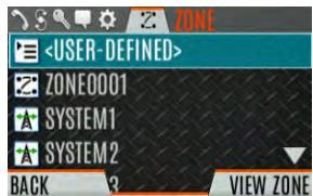
4.10 SELECT ZONE/System
A System is a group of channels or talkgroups that share a common set of parameters as programmed using RPM2. For example, a Trunking system defines the parameters needed to communicate on an infrastructure by agency or geographical region, such as WACN, System ID, Talkgroups, etc. A conventional system defines the channel set used and any specific signaling attributes (see RPM2 online help for more information on System attributes).
A Zone is an OPTIONAL container that can hold channels or talkgroups from a variety of systems (see Section 5.3). In other words, each member of a Zone belongs to an underlying system. Zones are always listed first in the Zone/System menu and are designated by the icon. A button on the radio can be programmed to scroll through available zones/systems (see Section 6.5).

NOTE
If enabled via radio programming, systems are not displayed in the ZONE menu, only zones are displayed.
Or
To select a zone/system via the menu:
- Press the Menu/Select button to access the menus.
- Use the left or right navigation buttons to display the ZONE menu. The currently selected zone/system is highlighted. A personality can have up to 512 systems and up to 250 Zones, independent of banks or channels.
Use the up or down navigation buttons to highlight the desired zone/system. Press and hold the up or down button to scroll repetitively; the menu wraps to allow quick access to a zone/system.
Enter the number of the zone/system to go directly to that selection in the list. Press the NUMERIC softkey to toggle the left, right, up, down navigation buttons to their alternate number function.
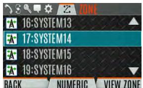
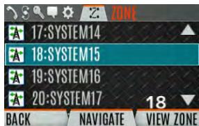
- Press the VIEW ZONE soft key to view channels in the zone/system or select the desired zone/system using the Menu/Select button.
4.11 SELECT GROUP/CHANNEL AND BANK
The radio can be programmed with 1,250 talkgroups or 1000 channels per personality. Use the Group/Channel knob to select groups/channels 1 - 16. Use the A/B/C switch to set the bank. The selected bank is indicated on the display.
Bank A: Channel A1 - A16 (1-16)
Bank B: Channel B1 - B16 (17-32)
Bank C: Channel C1 - C16 (33-48)
If your system has more than 48 groups/channels, a button on the radio can be programmed for the SEL CHAN/GRP option. This allows you to select a "super bank," providing access to groups/channels beyond the first 48.
ZONES have a limit of 64 entries per zone and cannot be "superbanked."
Direct Channel Entry
A button on the radio can be programmed for Direct Channel Entry, which allows the user to enter the talkgroup/channel number directly from the keypad. Press the NUMERIC softkey to toggle the left, right, up, down navigation buttons to their alternate number function.
The radio can be programmed for one of the following Direct Channel Entry options:
- When a Zone is selected on the radio, Direct Channel Entry performs a lookup using the currently selected system's group list.
Or
- When a Zone is selected on the radio, Direct Channel Entry performs a lookup using the currently selected Zone's system/group list.
4.12 LOCK/UNLOCK KEYPAD
There are two levels of keypad lock available: Keypad Lock and Radio Lock. Keypad lock only locks the navigation keys (except for use in unlock), programmable softkeys, and DTMF keypad. Radio lock disables all physical keys and knobs except:
The three-position switch
- PTT
- Emergency Button
- Any User Programmable Button (UPB) programmed for Monitor/Clear. This is required to allow Monitor/Clear to function for two-button emergency clear.
The A/B/C switch or a button on the radio can be programmed to lock the keypad/radio. If the keypad was locked via a switch, moving the switch to another position will unlock the keypad. If locked via a button, the navigation keys must be used to enter the unlock sequence of Left, Right, Up, Down.

NOTE
See Section 6.5 for the various options that can be programmed to the radio buttons and switches.
4.13 GROUP CALLS
4.13.1 Transmit a Group Call
A talkgroup is a group of radios that you want to have private conversations with. These groups can be divided into areas such as state, region, county, or large special events.
Turn the Channel/Group knob to select the desired group (see Figure 4-1). Press PTT to transmit.
Or
A button on the radio can be programmed for DIRECT CHANNEL ENTRY to allow the user to enter the talkgroup/channel number. Press PTT to transmit.
Or
To transmit a group call:
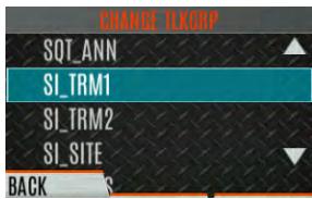
- In P25 Conventional, the talkgroup for the selected channel may be overridden as follows: Press the Menu/Select button to access the main menu.
- Press the left or right navigation buttons to display the CALL menu.
- Press the up or down navigation buttons to highlight CHANGE TLKGRP and press the Menu/Select button.
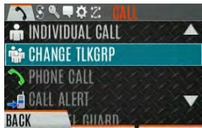
- Press the up or down navigation buttons to highlight and the desired talkgroup and press the Menu/Select button. After selecting the new talkgroup, the radio returns to the main screen.
- Press the PTT button to transmit.
4.13.2 Receive a Group Call
When receiving a group call, the status area of the idle display toggles between the Unit Name and the Group Name of the transmitting radio. If either of those names is not programmed, the corresponding ID number is displayed.

NOTE
If an in-band alias for the transmitting radio/console is sent to the receiving radios, the receiving radios display that alias instead of the Unit ID or the I-CALL/ Alias set contained in the receiving radio's personality, if any. The Alias alternates with the talkgroup name in the lower right display of the radio.
4.14 INDIVIDUAL CALLS
An individual call is used to make a call to one radio as opposed to a group of radios.
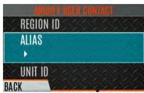
4.14.1 Add/Edit Contact from the Radio
- Press Menu/Select button to access the main menu.
- Press the left or right navigation buttons to display the CALL menu.
- Press the up or down navigation buttons to highlight INDIVIDUAL CALL and press the Menu/Select button.
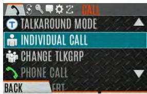
- Press the OPTIONS softkey.
- Press Menu/Select button to select MANAGE.
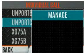
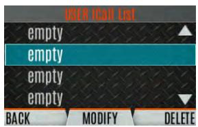
- Select MODIFY to edit/create a User Contact, or select DELETE to remove a contact from the list.
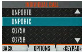
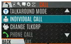
4.14.2 Transmit an Individual Call
- Press Menu/Select button to access the main menu.
- Press the left or right navigation buttons to display the CALL menu.
- Press the up or down navigation buttons to highlight INDIVIDUAL CALL and press the Menu/Select button.
- Use the up or down navigation buttons to highlight the unit to call and press the Menu/Select button, or select KEYPAD to enter the Unit ID.
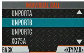
- Press PTT to make the call. When transmitting an Individual Call, the radio displays the called radio's name or Unit ID. If the radio is programmed for Acknowledged Individual Call, the radio displays "CALL QUEUED" until the callee answers or rejects the call.
- After the callee answers, press PTT to respond.
- Press the right navigation button to end the call.
How long the radio remains in Individual Call mode with no activity is programmable.
4.14.3 Receiving an Individual Call
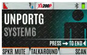
- When receiving an Individual Call, the radio displays the calling radio's name or Unit ID. The radio will also display "Press → to END."

- Press the PTT button to respond or the right navigation button to END/Reject the call. How long the radio remains in the Individual Call mode with no activity is programmable.
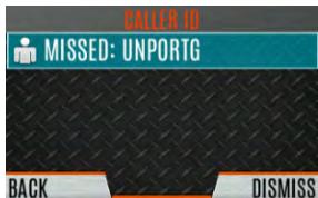
- The radio rings and indicates a missed call if you do not respond. The ring sounds until you press PTT, view the missed call menu using the up navigation button, change channel/group/system, or power cycle the radio.
- The radio can store up to ten (10) missed call entries. Select one of these entries to call the unit back or press the DISMISS soft key to clear the entry.
4.15 USER PROFILES
XL Connect Series radios support User Profiles (also referred to as "My Profile"). A User Profile is a grouping of preset configurations that allow the user to change radio operation based on current activity/scenario. For example, the radio can be programmed with profiles named Noisy, Fire, etc., and the radio user can switch profiles on the radio depending on the environment they are entering. User Profile selection persists across system/group changes and power cycles. Up to 10 profiles can be programmed to the radio. When you activate a new personality, the selected Profile changes to None.
A "Covert" Profile is installed on the radio by default. This profile cannot be modified or deleted. The following attributes apply when the Covert profile is active:
- The speaker is enabled.
- All tones are disabled.
- Keypad tones are disabled.
Voice Annunciation is disabled. - The front display backlight is disabled.
-
The top backlight is turned off.
-
The indicator LED is disabled.
- All other attributes remain at their current value.
Press the radio keypad sequence LEFT-RIGHT-UP-DOWN to exit Covert Mode.
To change the currently selected Profile:
- Press the Menu/Select button to access the menu.
- Press the left or right navigation buttons until the UTILITY menu is displayed.
- Press the up or down navigation buttons to highlight PROGRAM and press the Menu/Select button.
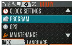
- Press the left or right navigation buttons until the PROFILES menu is displayed.
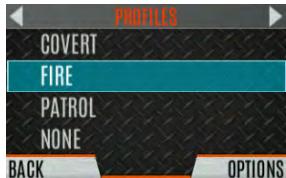
- Press the up or down navigation buttons to select the desired Profile and press the Menu/Select button.
A profile change persists across system/channel changes and power cycles.

NOTE
A button on the radio keypad can be used to toggle profiles. See Section 6.5.1.
4.16 NOISE CANCELLATION
XL Connect Series portable radios feature L3Harris' proprietary noise suppression capability to provide clear and crisp voice quality in high-noise environments. This can be used in any mode, including analog and digital communications.
The radio has two microphones; one located at the top and front of the radio (primary) and one on the back of the radio (secondary). When noise cancellation is enabled, voice is picked up by the front microphone, and noise is picked up from the rear microphone.
In the case where noise cancellation is enabled and a speaker microphone is attached to the radio, talk into the speaker microphone. In this mode, the radio's front microphone is used to pick up the surrounding noise, and the other microphone is unused. See Section 4.16.4 for more information. If the secondary microphone is blocked, the radio operates as though noise cancellation is turned off.
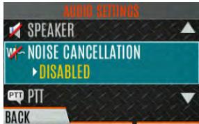
4.16.1 Enable Noise Cancellation
To enable Noise Cancellation:
- Press the Menu/Select button to access the menu.
- Press the left or right navigation buttons until the UTILITY menu is displayed.
- Press the up or down navigation buttons to highlight AUDIO SETTINGS and press the Menu/Select button.
- Press the up or down navigation buttons to highlight NOISE CANCELLATION. Toggle Noise Cancellation ENABLED/DISABLED using the Menu/Select button.
Refer to Section 5.5 for more information on the Audio Settings menu.
4.16.2 Using Noise Cancellation
When using the noise cancellation feature, observe the following:
- Verify NOISE CANCELLATION is enabled (see Section 4.16.1).
- Talk within two (2) inches of the primary microphone (see Figure 4-3).
- Ensure the primary and secondary microphones are not covered. See Section 4.16.4 for more information on the primary and secondary microphones.
- Speak clearly, loudly, and with authority.
- In very noisy environments, it is o.k. to yell into the radio. The radio can handle loud input levels.

Figure 4-3: Using Noise Cancellation
4.16.3 The Effect of Distance from the Microphone
Unlike a normal microphone system, noise cancellation makes the level of your voice diminish quickly as you move away from the radio. The radio starts to see your voice as surrounding noise. Whereas you may be comfortable speaking up to a foot away under normal operation, noise cancellation requires that you hold the radio close.
4.16.4 Primary versus Secondary Microphone
4.16.4.1 Without a Speaker Microphone Attached
The primary microphone is located on top front of the radio, and the secondary is on the back of the radio (refer to Figure 4-1 for microphone locations).
4.16.4.2 With a Speaker Microphone Attached
When a speaker microphone is attached, the radio electronically switches over to use the radio's front microphone as secondary. The microphone on the attached speaker microphone becomes primary.
4.16.5 When using a Self-Contained Breathing Apparatus (SCBA) Mask
When using an SCBA mask, the primary microphone can be held directly against the voice port. If the SCBA has a voice amplifier, the same rule applies. Ensure that the secondary microphone is uncovered. If possible, point the secondary microphone toward the noise source.
4.17 PTT OPTIONS
The radio can be programmed via RPM2 with one of the following PTT options:
- Radio and Accessory - In this mode, when the radio is PTTed, the audio source will correspond with the PTT source.
If the source of PTT is radio, the audio is routed via the radio microphone.
If the source of PTT is an external microphone accessory, the audio is routed via the external microphone accessory.
- Accessory Only - Any PTT input will have the audio routed through the external microphone accessory.

NOTE
The Bluetooth Speaker Mic is unaffected by this setting. PT Ting the Bluetooth Speaker Mic always results in audio being routed via the Bluetooth Speaker Mic.
4.18 VOICE ANNUNCIATION
When enabled via programming, Voice Annunciation provides audible feedback for various radio operations. The radio can be programmed to play an audio message for any or all the following. This message can be a pre-recorded (canned) message or a user-recorded message.
Zone changes
- Channel changes
- System changes
- Encryption On/Off
- Noise Cancellation On/Off
- Scan On/Off
- Talkaround On/Off
Monitor Mode On/Off
Three Position switch change
For more information on configuring the radio for Voice Annunciation, refer to the Voice Annunciation Feature Manual 14221-7200-6110.
4.19 ENABLE/DISABLE ENCRYPTION
A switch or a button on the radio can be programmed to enable/disable encryption.

See Section 6.5 for the various options that can be programmed to the radio buttons and switches.
Or
Turn encryption on or off via the Security Menu:
- Press the Menu/Select button to access the menus.
- Use the left or right navigation buttons button to highlight and select the SECURITY menu.
- Use the up or down navigation buttons button to highlight ENCRYPTION. Toggle encryption enabled/disabled using the Menu/Select button. This option is grayed out if any switch is programmed for encryption, or if Encryption Mode in the radio's personality is programmed "Forced On."
- If a channel is programmed to be encrypted, an optional key icon appears on the main display when encryption is enabled. The system must also be programmed for encryption.
-
When encryption is enabled and you use any channel not configured for encryption, the radio allows PTT. The signal is transmitted unencrypted.
-
Systems configured for Global Encryption (enabled in the Security menu) can display an optional Global Encryption icon in addition to or instead of a key icon (Section 5.20.2).
4.20 TRANSMIT ENABLE/DISABLE
When transmit is disabled, all forms of transmission from the radio are disabled, including Bluetooth. This is designed for use in explosive atmospheres.
4.21 CHANNEL GUARD (ANALOG CONVENTIONAL ONLY)
Channel Guard is L3Harris' trademark for CTCSS (tone squelch) and CDCSS (digital tone squelch).

NOTE
The Channel Guard menu is only accessible if the System is setup for CG SEL in the radio's personality.
To select the Channel Guard tone:
- Press Menu/Select button to access the main menu.
- Use the left or right navigation buttons to display the CALL menu.
- Use the up or down navigation buttons to highlight CHANNEL GUARD and press the Menu/Select button.
- Use the up or down navigation buttons to highlight RECEIVE GUARD or TRANSMIT GUARD and press the Menu/Select button.
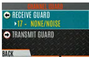
- Use the up or down navigation buttons to highlight the desired option from the list and select using the Menu/Select button.
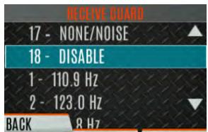
- The Channel Guard frequency is displayed on the main display.
The Channel Info screen and Channel Edit screen will change depending on this selection. See Sections 5.4 and 6.3 for more information.

NOTE
A button on the radio can be programmed for Channel Guard Override (see Section 6.5).
4.22 USE TALKAROUND TO BYPASS REPEATER (ANALOG AND P25 CONVENTIONAL ONLY)
You can bypass the repeater system to communicate directly with other radios on your current channel's receive frequency. This is useful if you are out of range of a repeater or if a repeater is busy. You must be in range of the other radio.

NOTE
Talkaround can be enabled/disabled on a per-channel basis. When talkaround is disabled, the icon is shown on the front and top display. If talkaround is disabled for a channel (via the RPM2 personality), and the user tries to enable talkaround via the menus or knobs while on that channel, the radio emits a "boop" deny tone. Additionally, if talkaround is disabled on a channel, the talkaround programmable button becomes inoperable and the radio boops.
To enable talkaround:
- Press Menu/Select button to access the main menu.
- Press the left or right navigation buttons to display the CALL menu.
- Press the up or down navigation buttons to highlight TALKAROUND MODE.
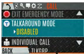
- Press the Menu/Select button to toggle TALKAROUND MODE to ENABLED.
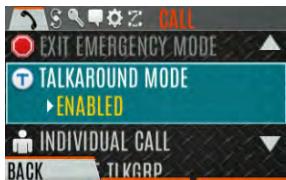
- The optional talkaround icon appears. Calls are now made on the receive frequency until you disable talkaround mode via the CALL menu. Power cycling the radio does not disable talkaround.
Or
A button or switch can be programmed to toggle talkaround enable/disabled. See Section 6.5 for the various options that can be programmed to the radio buttons and switches.
If the talkaround Indication feature is enabled using RPM2, the radio will play a unique grant tone when a call is placed on a simplex channel or when talkaround has been enabled on a duplex channel. This feature applies to both Analog and P25 Conventional systems. It optionally allows the radio to also play the same tone when it receives a call while operating in simplex or talkaround. If configured, the radio plays the tone at the selected volume level.

NOTE
The tone will not play on systems configured with MDC.
Talkaround Indication can be specified for each individual Analog and P25 Conventional system configured in personality. The following options can be selected, and apply only when the radio is on a simplex channel or when talkaround has been enabled by the user:
- Disabled: (This is the default option.) When this option is selected, the radio plays the standard grant tone when a call is placed. The radio does not play a tone when a call is received.
- Transmit Only: When this option is selected, the radio plays a different "talkaround" grant tone when a call is placed. The radio does not play a tone when a call is received.
- Transmit and Receive: When this option is selected, the radio plays a different "talkaround" grant tone when a call is placed, and at the beginning of a received call.

NOTE
In the radio personality, the "Alert Tone" parameter needs to be enabled for each channel on the Conventional Frequency Set. The "Ready to Talk Tone" parameter must also be enabled for the Talk Around Indication tone to be played when the radio is keyed.
Type 99 is L3Harris' name for in-band, two-tone sequential signaling. It is a conventional signaling protocol used to control the muting and unmuting of a radio. This signaling is commonly used for selective calling of individual units or groups of units in a conventional system.
In Type 99 tone systems, calls are not heard until the radio detects the proper two-tone sequence. This, in conjunction with squelch, prevents the user from hearing noise or undesired conversations. When the radio detects the second tone, it sounds the appropriate Type 99 alert tone. After the second tone stops, the receiver audio path is opened for the user to receive messages.
4.23.1 Enable/Disable Type 99
To enable Type 99:
- Press Menu/Select button to access the main menu.
- Press the left or right navigation buttons to display the CALL menu.
- Press the up or down navigation buttons to highlight T99 TOGGLE.
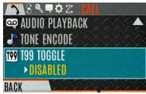
- Press the Menu/Select button to change T99 TOGGLE between ENABLED and DISABLED. T99 is displayed in the top of the radio display when Type 99 is enabled.
Or
A button or switch can be programmed to enable/disable Type 99 (see Section 6.5).
4.23.2 Disable After PTT
If this option is programmed using RPM2, Type 99 is disabled after the radio user activates the PTT. This allows the radio user to monitor traffic on the channel (after a PTT action) without pressing the monitor button.
Can be used in conjunction with the "Auto Reset" option (see Section 4.23.3) to disable Type 99 after a PTT and automatically reset, or enable, Type 99 after 30 seconds.
4.23.3 Auto Reset
If this option is programmed using RPM2, Type 99 is automatically reset, or turned back on, after 30 seconds. Can be used in conjunction with the "Disable After PTT" option (see Section 4.23.2) to disable Type 99 after a PTT and automatically reset, or enable, Type 99 after 30 seconds.
4.24 CALL ALERT (PAGE)
4.24.1 Send Alert
To send an alert:
- Press the Menu/Select button to access the main menu.
- Press the left or right navigation buttons to display the CALL menu.
- Press the up or down navigation buttons to highlight CALL ALERT and press the Menu/Select button.
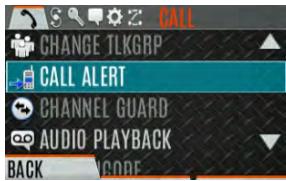
- Press the up or down navigation buttons to highlight the desired unit from the list and press the Menu/Select button, or select KEYPAD to enter the Unit ID.
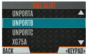
- Press PTT to send the page.
4.24.2 Receive Alert
- When receiving a Call Alert, the radio displays the calling radio's name or Unit ID.
- The radio rings and indicates a missed call. The ring sounds continuously until you press PTT, press the CLR MISSED softkey, change group/system, or power cycle the radio.
4.25 TELEPHONE INTERCONNECT
- Press the Menu/Select button to access the main menu.
- Press the left or right navigation buttons to display the CALL menu.
- Press the up or down navigation buttons to highlight PHONE CALL and press the Menu/Select button.
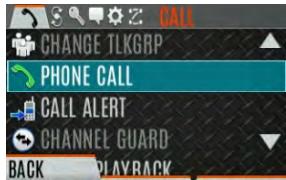
- Select an entry from the list of pre-programmed entries or click DIRECT DIAL to enter the number directly. Direct Dial entries can have up to 31 characters (0-9, *, #, or a space; the space correlates to a pause.) Select OPTIONS to view details about the highlighted pre-programmed entry. The radio supports up to 255 pre-programmed entries.
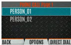
- Press PTT to initiate the phone call. Press the right navigation button to end the call.
The radio does not permit telephone interconnect calls during an emergency. While in a phone call, the radio ignores all types of calls EXCEPT a System All Call. If the radio receives a System All Call while in a phone call, it immediately drops the phone call and accepts the All Call.
4.26 DTMF
XL Series portables support the transmission of DTMF tones corresponding to the numbers/characters on the keypad. To overdial numbers/characters, press and hold the PTT button, and then press the corresponding keys one at a time on the keypad. Valid keys for DTMF tones are: 1, 2, 3, 4, 5, 6, 7, 8, 9, *, 0, and #.

NOTE
For conventional or P25 Conventional systems, DTMF tones only play if the current system is programmed for DTMF (part of general System configuration). DTMF tones are always enabled for P25 Trunking systems.
4.27 AUDIO PLAYBACK
The Audio Playback feature allows the user to playback a previously received call. Recordings are stored in the radio's RAM and are not persistent across power cycles. The radio stores the last five recorded calls up to one minute each.
A button on the radio can be programmed to replay the last recorded call. To playback the last received call from a button:
- Press the button programmed for audio playback. The last call received before the button was pressed is played each time the button is pressed.
- Additional incoming calls will be recorded in the background, but pressing the button continues to replay the captured call until reset.
- To reset the feature and allow a new call to be captured, press and hold the button until you hear a two-tone chirp. At this point, the button can be used to capture a new incoming call.
You can also playback one of the last five calls received via the menu.
To playback a previously received call from the menu:
- Press the Menu/Select button.
- Press the left or right navigation buttons to display the CALL menu.
- Press the up or down navigation buttons to highlight AUDIO PLAYBACK and press the Menu/Select button.
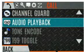
- Select the desired call from the list (the most recent call is at the top of the list) and press the select button. The selected call will be played.
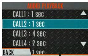
- If a button is also programmed for Audio Playback, pressing the button replays the call selected in the menu. The feature must be reset as above to use the button to capture a new call.
- If a button is not programmed for Audio Playback, then you must navigate back to the menu to play the call again.

Any incoming call that occurs during playback preempts the playback.
4.28 START SCAN
This procedure assumes that the scan list has been added and the radio is not in active scan. Refer to Section 5.13 for scan setup or Section 4.29 for stopping scan. Refer to Section 5.14.1.1, Section 5.14.1.2, and Section 5.14.1.3 for home and priority channel descriptions.
To start scan:
- Press the Menu/Select button to access the main menu.
- Press the left or right navigation buttons to display the SCAN menu.
- Press the up or down navigation buttons to highlight START SCAN and press the Menu/Select button. START SCAN text changes to STOP SCAN.

- Press the BACK soft key to exit the scan menu.
- The scan icon is displayed on the idle display when scanning is enabled.
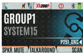
Or
To start scan:
- Press the Menu/Select button to access the main menu.
- Press the left or right navigation buttons to display the SCAN menu.
- Press the up or down navigation buttons to highlight SCAN Lists and press the Menu/Select button.

- Press the up or down navigation buttons to highlight the desired SCAN LIST and press the START SCAN soft key.
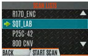
Or
A switch or button on the radio can be programmed to start/stop scan.

If a switch is programmed for start/stop scan, the menu for starting and stopping scan is disabled.

See Section 6.5 for the various options that can be programmed to the radio buttons and switches.
4.29 STOP SCAN
- Press the Menu/Select button to access the main menu.
- Press the left or right navigation buttons to display the SCAN menu.
- Press the up or down navigation buttons to highlight STOP SCAN and press the Menu/Select button.
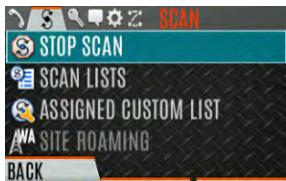
- Press the BACK soft key to exit the scan menu.
Or
- Press the Menu/Select button to access the main menu.
- Press the left or right navigation buttons to display the SCAN menu.
- Press the up or down navigation buttons to highlight SCAN Lists and press the Menu/Select button.
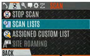
- Press the STOP SCAN soft key.
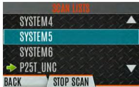
Or
A switch or button on the radio can be programmed to start/stop scan.

If a switch or button is programmed for start/stop scan, the menu for starting and stopping scan are disabled.

See Section 6.5 for the various options that can be programmed to the radio buttons and switches.
4.30 MONITOR AND SQUELCH TYPES (CONVENTIONAL ONLY)
The monitor function allows you to temporarily turn off selected squelch to monitor for traffic that may not normally break squelch. The type of squelch used depends on an analog or digital channel. A button or switch on the radio can be programmed to start or stop Monitor (see Section 6.5 for the various options that can be programmed to the radio buttons and switches.).
For analog channels, there is:
- Noise squelch - any received signal breaks squelch.
- Continuous Tone Coded Squelch (CTCSS) - squelch is selective based on tone code.
- Continuous Digital Coded Squelch (CDCSS) - squelch is selective based on digital code.
For digital channels, there is:
Monitor squelch - any received digital signal breaks squelch.
- Normal squelch - Received Network Access Code (NAC) must be correct to break squelch.
- Selective squelch - Received NAC and talkgroup Identification (ID) or unit ID must be correct to break squelch.

NOTE
During encrypted operations, the radio only unmutes when receiving with the same key.
4.31 NUISANCE DELETE
A channel can be deleted temporarily from the scan list. The selected channel, priority 1, and priority 2 channels cannot be nuisance deleted. A button or switch on the radio can be programmed for nuisance delete (see Section 6.5 for the various options that can be programmed to the radio buttons and switches).

NOTE
Nuisance delete can only be performed on the active scan list.
To perform a nuisance delete from the menu:
- Press the Menu/Select button to access the main menu.
- Press the left or right navigation buttons to display the SCAN menu.
- Press the up or down navigation buttons to highlight SCAN Lists and press the Menu/Select button.
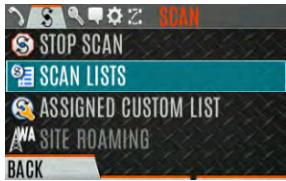
- Press the up or down navigation buttons to highlight the scan list and press the Menu/Select button. When scanning is started, indicates the active scan list; when scanning is stopped, indicates the active scan list.
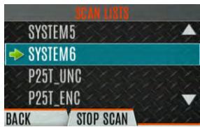
- Press the up or down navigation buttons to highlight the desired channel.
- Press the OPTIONS soft key.

- Press the up or down navigation buttons to highlight NUISANCE and press the Menu/Select button.
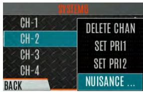
- The icon appears next to the channel and it will not be scanned.
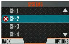
- Highlight the channel, press the OPTIONS soft key, and select ADD BACK to add channel back to scan list. If you do not add the channel back to the list, the channel will return to the scan list when you cycle radio power or activate a personality.
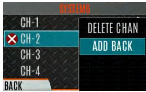
- Press the BACK soft key to exit the channel list.
- Press the BACK soft key to exit the scan list display.
4.32 FAILSOFT
4.32.1 Conventional Failsoft (EDACS Only)
In the unlikely event of an EDACS system failure, communications can take place in Conventional Failsoft mode. The radio is automatically directed to a communications channel set up for this purpose. An increase in activity on the channel during Conventional Failsoft operation may be noticed, so be careful not to transmit until the channel is clear.
Operation during Conventional Failsoft is the same as operation on a conventional system, except that it is not possible to select a communications channel or use emergency and special call. When trunking is restored, the radio automatically returns to normal operation.

NOTE
Emergency and special calls are not operational during Conventional Failsoft.
4.32.2 Failsoft (P25 Trunked)
When the site-link to the VNIC is down, the site is operating in Failsoft mode. Radios operating on that site can still communicate with each other, but not with the rest of the system. The radio provides a visual indicator (A! icon) on the display and plays a tone for a configured interval to indicate that the site is in Failsoft. This tone interval range is 0 to 120 seconds. This tone is not played during incoming voice or PTT.
The radio can be programmed to enable emergency mode. Unit name displays on dispatcher console if an emergency signal is received from another radio on a digital channel.
4.33.1 Declaring an Emergency Call
To declare an emergency:
- Press and hold the emergency button on the radio or the speaker microphone. The length of time you need to hold the button is configured using RPM2.
- The emergency icon is displayed on the idle display.
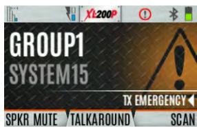
- For digital channels, the radio transmits the talkgroup or radio ID to the dispatch console and receiving radio.
- The radio can be programmed to have a dedicated emergency channel, which can be activated from analog or digital channels.
- The radio can also be programmed to send an Emergency Alarm in addition to or in place of the emergency call (P25 modes).
The radio goes through transmit and receive cycles if so configured. Speak into the microphone while the radio is transmitting or press PTT to talk.
- To exit emergency, power cycle the radio or select EXIT EMERGENCY from the CALL menu.
If enabled via programming, you can clear an emergency by pressing the button programmed for the Monitor/Clear function and then the emergency button.
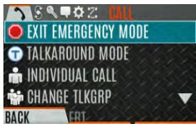
4.33.2 Receiving an Emergency Call
When receiving an Emergency Call, an alert tone sounds (if tones are enabled) and an emergency indication is displayed. The unit ID and/or unit name of the unit in emergency is displayed. While the emergency display is active, press PTT to respond to the emergency caller.
4.33.3 Stealth Emergency
The radio can be programmed with the following emergency behavior:
No audio indications when declaring an emergency.
Or
No visual indications when declaring an emergency.
Or
No audio and no visual indications when declaring an emergency.
During stealth mode, the radio will not receive any type of call. Once the user presses the PTT button, the radio display and audio return to normal.
4.34 MDC-1200 (ANALOG CONVENTIONAL ONLY)
MDC-1200 is a legacy in-band signaling protocol that provides the radio with the ability to transmit and receive a unique PTT ID. This PTT ID can be decoded by receiving radios and displayed as a hexadecimal number or an alias string. In addition, MDC-1200 provides radios with the ability to transmit emergency status to a console. Refer to the MDC-1200 Feature Manual, 14221-7200-6000, for complete instructions on configuring and using this feature.
4.34.1 Normal PTT Operation
If MDC signaling on PTT press is enabled using RPM2, the radio transmits an MDC PTT ID message when PTT is pressed. If the Sidetone option is enabled using RPM2, the radio plays a Ready-to-Talk (RTT) tone after the MDC pre-signaling has been transmitted.
If MDC signaling on PTT release is enabled (using RPM2), the radio transmits post-call MDC signaling when PTT is released.
- IF STE is enabled (using RPM2), the MDC post-call signaling is transmitted after STE is sent on PTT release only.
- MDC post-call signaling is also sent when there is a radio unkey due to Carrier Control Timeout (CCT). Normal CCT alert tones occur prior to unkey.
4.34.2 MDC PTT ID Receive Handling
When the radio receives an MDC PTT ID, it searches the MDC ID Alias List for an alias associated with the ID. If one is found, it displays the alias. If none is found, the radio displays the ID in hexadecimal.
4.34.3 Emergency Declaration
Emergency declaration is accomplished by the radio generating an MDC Emergency PTT message. An Emergency is considered acknowledged when the radio receives an "Ack To Emergency" PTT message with an ID which matches its own ID. If Emergency Audio is enabled and the PTT Sidetone option is enabled, the radio plays the Ready-to-Talk tone after the MDC Emergency PTT signaling is transmitted.
- If an MDC Alert on ACK is enabled, the radio plays an ACK tone when the MDC emergency is acknowledged.
- If audio tones are enabled, the radio plays an ACK tone if the emergency is not acknowledged within the programmed number of retries.
4.35 WI-FI CLIENT SELECTION
XL portable radios support up to 24 different Wi-Fi networks configurable via programming, with an option to select one of the configured networks as default.

NOTE
These 24 Wi-Fi networks are considered radio administrator approved and Trusted Wi-Fi Networks (TWiN) on which the radio can operate.
The radio will always join the network configured as the highest priority in the personality when multiple TWiNs are available.
To change the selected Wi-Fi network:
- From the UTILITY menu, select Wi-Fi Client.
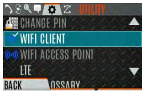
- From here, select a network from the list, add a network, view details about the selected network, or remove the selected network.
- Select ADD NEW to add a new network.
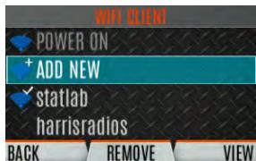
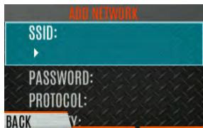
- Highlight and select SSID. Use the keypad on the radio to enter the SSID and press the ENTER softkey.
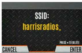
- Highlight and select PASSWORD. Use the keypad on the radio to enter the password.
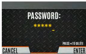
- Press the Menu/Select button to cycle through available Protocol selections (None, WPA, or WPA2-PSK).
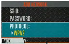
- Press the Menu/Select button to cycle through available Priority selections (Low, Medium, or High).
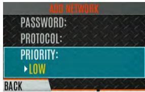
4.36 STEALTH MODE
For some users, it is important to be able to turn off the radio's display lights and side tones, but not the radio traffic. For example, in covert operations, lights and sounds could inadvertently expose an otherwise unobservable radio user. For this purpose, the radio has a Stealth feature that disables the radio display lights, indicator lights, audible alert, and side tones. When Stealth Mode is on, the radio continues to scan the programmed list of Talk Groups and the user can key-up on the selected Talk Group. A button can be programmed via RPM2 to enable/disable Stealth Mode.
The following Stealth Mode options are configurable via RPM2:
- Persistence Enabled - Specify whether or not Stealth Mode persists after the radio is powered down.
- LCD Enabled - Specify if the LCD is enabled or disabled for Stealth Mode.
LED Enabled - Specify if the LED is enabled or disabled for Stealth Mode. - Backlight Enabled - Specify if the Backlight is enabled or disabled for Stealth Mode.
- Side/Alert Tones Enabled - Specify if side tones and alert tones are enabled or disabled for Stealth Mode.
Voice Annunciation Enabled - Specify if Voice Annunciation is enabled or disabled for Stealth Mode. - Channel/Group Knob Enabled - Specify if the Channel/Group Knob is enabled or disabled for Stealth Mode.
- Top Display Enabled - Specify if the Top Display is enabled or disabled for Stealth Mode.
- Top Display Minimum Brightness - When this option is enabled, the top display is enabled at the minimum brightness when the radio is in Stealth Mode.
5. ADVANCED OPERATIONS
5.1 VIEW/CHANGE PERSONALITIES
Personalities contain radio programming information such as frequencies, channels, stations, and talk groups. Up to ten different personalities can be stored in the radio, but only one can be active at a time.
5.1.1 View Personalities
- At the main display, press the Menu/Select button to access the main menu.
- Press the left or right navigation buttons to display the UTILITY menu.
- Press the up or down navigation buttons to highlight PROGRAM and press the Menu/Select button. An arrow indicates the currently active personality.
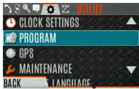
- Press the OPTIONS soft key.
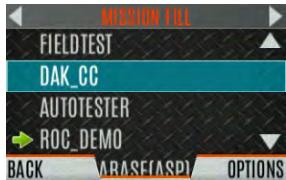
- Select VIEW PLAN INFO to view.
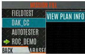
- The radio displays the plan's filename. Personality information appears if the field was filled out using RPM2.
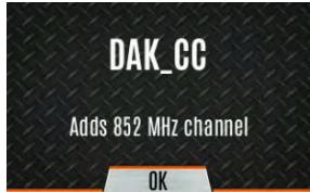
5.1.2 Change Active Personality
To change the active personality:
- At main display, press the Menu/Select button to access the main menu.
- Press the left or right navigation buttons to display the UTILITY menu.
- Press the up or down navigation buttons to highlight PROGRAM and press the Menu/Select button.
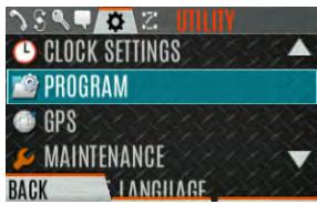
- Press the up or down navigation buttons to highlight the desired personality and press the Menu/Select button. indicates the currently active personality.
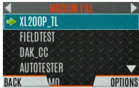
- Press the YES soft key to confirm personality activation. If the personality has a power-up PIN, you are prompted to enter the PIN before activation continues.

- The IN PROGRESS screen is displayed while plan activation is in progress.

- If personality is activated, the radio displays PLAN COMPLETE followed by the name of the personality. Press the OK soft key.

- You cannot activate a personality when the radio is transmitting an emergency.
- A Failed message may be displayed for errors such as invalid syntax in the fill or some other invalid parameter.
5.2 SITUATIONAL AWARENESS (SA) - P25 CONVENTIONAL ONLY
Situational Awareness is a feature in which the radio receives SA position from other units configured to send the SA packets. The SA display shows the positions of the other radios (units) relative to the radio. To make use of SA, all radios need to have a uniquely programmed Unit ID.
To display Situational Awareness Info:
- Press the Menu/Select button to access the main menu.
- Press the left or right navigation buttons to display the UTILITY menu.
- Press the up or down navigation buttons to select GPS and press the Menu/Select button.
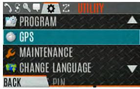
- Press the up or down navigation buttons to select POSITION INFO and press the Menu/Select button.
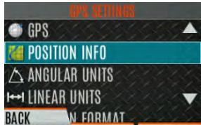
- Press the NEXT soft key.

-
Press the left or right navigation buttons to view the location of each unit. The color of each unit indicates its status as follows. Only one status can be shown at a time and are listed in priority order:
-
Grey – Unselected, no status
Red - Unselected, In Emergency
Orange - Unselected, Low Battery - Blue - Unselected, Scanning
- Green - Selected, no status
- Green/Red - Selected, In Emergency
- Green/Orange - Selected, Low Battery
-
Green/Blue - Selected, Scanning
-
GPS of this radio is shown by the center dot as follows:
-
Green - Tracking
Orange - Last known position
Red-Searching -
Press the up or down navigation buttons to zoom the display distance of current unit.

- Press the OPTIONS soft key. From here, select UNIT INFO to display details about the selected unit, select REFRESH to update information, or select EXIT.
5.3 USER-DEFINED ZONES/SYSTEMS
5.3.1 Command Tactical Zone
A Command Tactical Zone is defined at the radio.

A Command Tactical Zone is reset when a Personality is activated.
To create a Command Tactical Zone:
- Press the Menu/Select button to access the main menu.
- Press the left or right navigation buttons to display the ZONE menu.
- Press the up or down navigation buttons to highlight
and press the VIEW ZONE soft key.
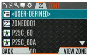
- Press the OPTIONS soft key.

- Press the up or down navigation buttons to select EDIT ZONE to create a zone or select RENAME ZONE to rename the Command Tactical Zone (up to 16 characters are allowed).
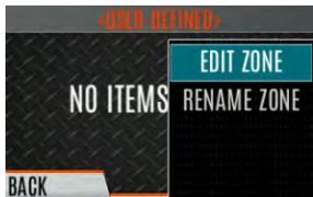
- Press the left or right navigation buttons to scroll through existing systems. Press the up or down navigation buttons to highlight desired channel/group.
-
Press the Menu/Select button to add or remove channel/group.
-
After adding all desired channels/groups, press the BACK soft key.
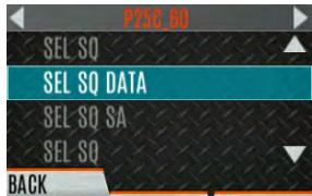
- Activate the Command Tactical Zone by selecting the SET ACTIVE soft key on the USER DEFINED screen, or by pressing the Menu/Select button when
is highlighted on the Zone menu.
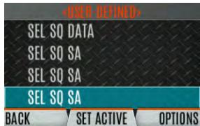
- After creating a Command Tactical Zone, select OPTIONS to edit the Command Tactical Zone, delete channels/groups, clear the zone, and rename the zone.
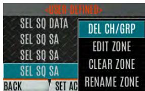
5.3.2 Mixed System Zone
Mixed System Zones are defined using RPM2 and cannot be edited on the radio. If a Mixed System Zone is not configured using RPM2, it will not appear on the radio. Up to 250 Mixed System Zones can be defined. You can view details about each channel/group. A user programmable button can be defined to scroll through just the mixed system zones.
To view Mixed System Zones:
- Press the Menu/Select button to access the main menu.
- Press the left or right navigation buttons to display the ZONE menu.
- Press the up or down navigation buttons to highlight the desired zone (Zones are indicated by the Z:icon) and select VIEW ZONE to view the groups/channels in the zone list.
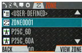
5.4 CHINFO MENU
The Channel Information (CH INFO) menu displays information about the currently selected channel. The information displayed varies between conventional and trunked systems. The Channel Information (CH INFO) menu display is only available if a Channel Edit Password has been programmed via RPM2.
To display channel information:
- Press while on the idle display.
- Press the up or down navigation buttons to scroll through the programmed channel settings.
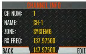
CONVENTIONAL OR P25 CHANNELS ONLY:
- Press the EDIT soft key.
- Enter the password. You may now select and change the values of the displayed channel parameters. The password remains active until power cycle. Refer to Section 6.3 for more information.
5.5 AUDIO SETTINGS
From this menu, you can set audio settings such as speaker mute, noise cancellation, PTT, and tones.
- Press the Menu/Select button to access the main menu.
- Press the left or right navigation buttons to display the UTILITY menu.
- Press the up or down navigation buttons highlight AUDIO SETTINGS and press the Menu/Select button.
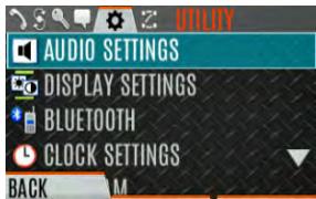
- Press the up or down navigation buttons to scroll through available audio settings. Press the Select/Menu button to change settings as desired:
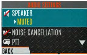
- SPEAKER - Mute or Unmute the speaker audio.
- NOISE CANCELLATION - Enable or disable noise cancellation. Noise cancellation reduces background noise during transmit.
-
PTT - Enable or disable Push-To-Talk (PTT). Disable PTT to prevent accidental keying, such as when the radio is in a holster or you are getting into a car.
-
TONES - Enable or disable alert tones (see Table 4-6).
-
KEYPAD TONES - Enable or disable keypad tones. When enabled, the radio plays a tone when a button on the keypad is pressed.
-
Press the BACK soft key to exit menu.
5.6 DISPLAY SETTINGS
To change display settings:
- Press the Menu/Select button to access the main menu.
- Press the left or right navigation buttons to display the UTILITY Menu.
- Press the up or down navigation buttons to highlight DISPLAY SETTINGS and press the Menu/Select button.
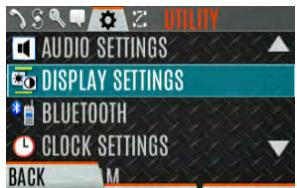
- Press the up or down navigation buttons and the Select/Menu button to change settings as desired:
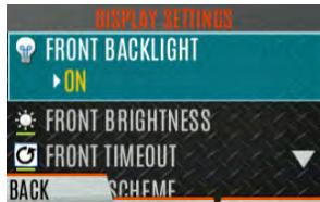
- COLOR SCHEME - Change the color scheme of the top and front displays for optimum viewing in day/night conditions.
- FRONT BACKLIGHT - Turn front display backlight on, off, momentary, or momentary (off). Momentary (off) is similar to momentary, but the backlight turns off completely and only comes on when the center navigation button is pressed.
- FRONT BRIGHTNESS - Set brightness level of front display. A level of 0 has same effect as turning off backlight.
- FRONT TIMEOUT - Specify how long the radio needs to be inactive before the front display's backlight turns off.
- FRONT DISPLAY OFF - Turns the front display off completely. Press the Menu/Select button to turn the front display back on. When the front display is turned off, the only button functions that are allowed are:
PTT
Emergency
Toggle Profile
Flashlight
Toggle Stealth
Channel UpChannel Down
Volume Up
Volume Down
Press the Menu/Select button to disable this feature and turn the front display back on.
-
INDICATOR LED - Toggle the indicator LED ON/OFF.
-
Press the BACK soft key to exit the menu.
5.7 GPS SETTINGS

NOTE
The GPS SETTINGS menu item only appears if enabled using RPM2 and the feature is installed.
To access GPS settings:
- Press the Menu/Select button to access the main menu.
- Press the left or right navigation buttons to display the UTILITY menu.
- Press the up or down navigation buttons to highlight GPS and press the Menu/Select button.
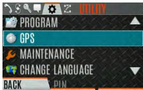
- Use the up or down navigation buttons and the Select/Menu button to change settings as desired:
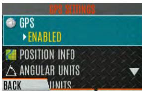
GPS - Enable or disable internal GPS.
- POSITION INFO - See Section 5.8.
- ANGULAR UNITS - Set unit of measurement of displayed angular units: CARDINAL, DEGREES, or MILS.
LINEAR UNITS - Set unit of measurement of displayed linear units: STATUTE, METRIC, or NAUTICAL.
- POSITION FORMAT- Set format of displayed position information: Latitude/Longitude Decimal Degrees (LAT LONG DD), Latitude/Longitude Degrees Minutes Seconds (LAT/LONG DMS), LAT/LONG DM, Military Grid Reference System (MGRS), or Universal Transverse Mercator (UTM).
- SA OVER NETWORK - When Enabled, the radio sends GPS data to an L3Harris-supplied PC client using RNDIS networking.
- Press the BACK soft key to exit the menu.
5.8 POSITION INFO
The Position Info screen displays the radio user's location information. GPS must be enabled in the GPS Settings (see Section 5.7).
To display position info:
- Press the Menu/Select button to access the main menu.
- Press the left or right navigation buttons to display the UTILITY menu.
- Press the up or down navigation buttons to highlight POSITION INFO and press the Menu/Select button.
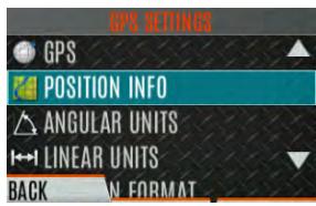
- Press the up or down navigation buttons to scroll through available location information.
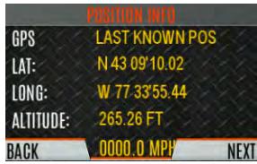
5.9 WI-FI
The XL portable supports programming via Wi-Fi. Refer to Appendix A for information on configuring Wi-Fi.

ISED restricts 5150-5250 MHz to indoor use only.
To enable Wi-Fi programming mode on the radio:
- Ensure the radio is powered off.
- Press and hold the middle side button and PTT button (see Figure 3-1).
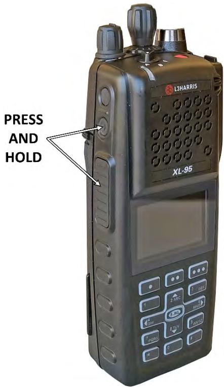
Figure 5-1: Enabling Wi-Fi
- Power on the radio.
- The WIFI INSTALL ACTIVE screen is displayed (Figure 5-2). The radio displays DISCONNECTED if not connected to a wireless network or CONNECTED if connected to a wireless network.
WIFI INSTALL ACTIVE
CYCLE POWER TO EXIT
192.168.11.4
PRESS SELECT FOR 'WIFI CLIENT' MENU

Figure 5-2: Wi-Fi Install Active
NOTE
Refer to Section 4.35 for more information about Wi-Fi Client selection.
5.10 BLUETOOTH

The BLUETOOTH menu item only appears if enabled using RPM2 and if the feature is installed.
5.10.1 Enable Bluetooth
To enable Bluetooth:
- Press the Menu/Select button to access the main menu.
- Press the left or right navigation buttons to display the UTILITY menu.
- Press the up or down navigation buttons to highlight BLUETOOTH and press the Menu/Select button.
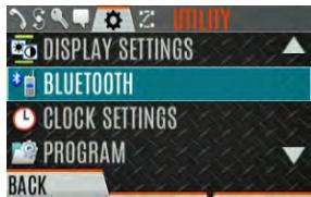
- Press the up or down navigation buttons to highlight ENABLED and press the Menu/Select button to toggle YES/NO.
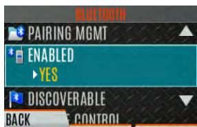
Or
A button or switch can be programmed to enable/disable Bluetooth.
5.10.2 Pair Devices
To pair devices:
- Press the Menu/Select button to access the main menu.
- Press the left or right navigation buttons to display the UTILITY menu.
- Press the up or down navigation buttons to highlight BLUETOOTH and press the Menu/Select button.
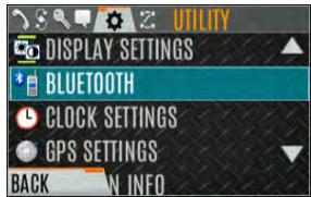
- Press the up or down navigation buttons to highlight PAIRING MGMT and press the Menu/Select button.
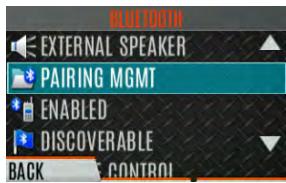
- Make sure device being paired is powered on and has discovery mode enabled to pair with the radio.
If no devices are found and Bluetooth is enabled, only the ADD NEW soft key is available. If devices are paired, the OPTIONS soft key appears.

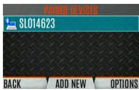
- Press the ADD NEW soft key to select a device to pair.
- A list of available Bluetooth devices appears.
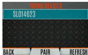
- Press the REFRESH soft key to refresh the device list if the desired device does not appear.
- Press the up or down navigation buttons highlight the desired device and press the PAIR softkey.
-
Pairing progress is displayed.
-
For Bluetooth 2.0 devices, a pin code screen appears.
Enter the pin code and select OK. - For Bluetooth 2.1 devices, a PASSKEY accept/deny screen appears. Select ACCEPT.
Accept the passkey on the Bluetooth 2.1 device as well.

- A PAIRING COMPLETE message appears when pairing is complete. Select OK. The paired device is then displayed in the PAIRED DEVICES list.

5.10.3 Reconnecting to Covert Bluetooth Microphone 12082-0684-01
When powering down, the radio and the microphone should be turned off one at a time, allowing the first device to completely shut down before turning off the second device.
Power Up Sequence:
- Power up the XL radio. Wait for power up to complete.
- Power up covert microphone 12082-0684-01.
- Wait for Bluetooth connection as indicated by the LED. When connected, the LED is on and blue.
- If the microphone LED indicates Idle or does not connect, press and release the PTT button.
5.10.4 Pair with the SCOTT EPIC 3 Radio Direct Interface (RDI) Voice Amplifier
The RDI Voice Amplifier enhances SCBA voice intelligibility when connected to the XL Portable via Bluetooth.
To turn the amplifier on and place into pairing mode:
- Press and hold the power button until the LED changes from green to red. This happens in about four (4) seconds.
- Release the power button.
- The LED starts blinking indicating the amp is in pairing mode.
- Ensure the LED is the same color blinking on and off indicating pairing mode. The amp will timeout of pairing mode quickly and the blinking will stop. If this happens before successful pairing, power off and restart from Step 1.
- If the LED is blinking between light red and dark red, then the amp is in programming mode. If you try to pair with the amplifier in this mode, it will identify itself as an RI version. Turn off power and restart from step 1.
5.11 CLOCK SETTINGS
To view/change clock settings:
- Press the Menu/Select button to access the main menu.
- Press the left or right navigation buttons to display the UTILITY menu.
- Press the up or down navigation buttons to highlight CLOCK SETTINGS and press the Menu/Select button.
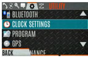
- Use the up or down navigation buttons and Menu/Select button to change settings as desired:
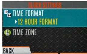
- TIME FORMAT- Set 12 or 24-hour time display format.
-
TIME ZONE - Set time zone relative to Universal Time Coordinated (UTC).
-
Press the BACK soft key to exit.
5.12 BATTERY INFO
To display battery information:
- Press the Menu/Select button to access the main menu.
- Press the left or right navigation buttons to display the UTILITY menu.
- Press the up or down navigation buttons to highlight MAINTENANCE and press the Menu/Select button.
- Press the up or down navigation buttons to highlight BATTERY INFO and press the Menu/Select button.
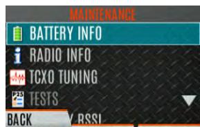
- Battery information is displayed (state, voltage, capacity, chemistry, etc.).


Use only L3Harris-approved batteries. Injury could occur from using an incorrect battery.
5.13 SELECT LANGUAGE
To change the language displayed by the radio:
- Press the Menu/Select button to access the main menu.
-
Press the left or right navigation buttons to display the UTILITY menu.
-
Press the up or down navigation buttons to highlight CHANGE LANGUAGE and press the Menu/Select button.
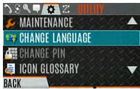
- Press the up or down navigation buttons to highlight the desired language and press the Menu/Select button.

5.14 SET UP SCAN
These procedures are used to set up the scan list, home channels, and priority channels.
To access the scan lists:
- Press the Menu/Select button to access the main menu.
- Press the left or right navigation buttons to display the SCAN menu.
- Press the up or down navigation buttons to highlight SCAN Lists and press the Menu/Select button. Refer to the following sections.


When using Preemptive Priority Scan, the frequencies in the list need to be unique.
5.14.1 Default, Priority 1, and Priority 2 Channels
5.14.1.1 Default Channel
This is the currently selected channel and is the channel you transmit on by default when you press PTT while the radio is actively scanning and is not responding to a just received call. Responding to a call the radio just received while scanning is called hang time. If hang time is set to 0 using RPM2, the radio always transmits on the default channel in scan.
5.14.1.2 Priority 1 Channel
This channel will be scanned more often than other channels in the list and will be scanned in between every other channel in the scan list. An example scan sequence would be P1 (priority 1), C2, P1, C3, P1, C4, etc. In addition, the priority channel is scanned even while actively receiving on a non-priority channel. For example, if the radio is actively receiving on C3 and activity is detected on P1, the radio drops C3 and switches to P1.
5.14.1.3 Priority 2 Channel
This channel is also scanned more often than others. An example scan sequence is P1, C2, P1, C3, P1, C4, P2, C5, P1, C6, P1, C7, P1, C8, P2, C9, etc. In addition, this channel is scanned even while actively receiving on a non-priority channel. For example, if the radio is actively receiving on C3 and activity is detected on P2, the radio drops C3 and switches to P2. Additionally, activity on P1 can also preempt P2, but P2 cannot preempt P1.
5.14.2 Trunked/Conventional Scanning
Trunked/conventional scanning adds the ability to scan multiple conventional and P25 conventional channels while still maintaining trunked radio operation. The radio can scan a conventional scan list while still receiving a trunked control channel and receiving trunked calls. Selection of which conventional scan list is associated with a given trunked system is done using RPM2 and cannot be changed on the radio. However, a user with access to the necessary menu layout (see Section 4.7) can edit the scan list members (both trunked groups and conventional channels on the selected Conventional Priority System). As the number of conventional channels being scanned increases, the time between scanning each channel increases (roughly 250 milliseconds per channel), with the consequent increase in the number of calls that will late-enter. To avoid missing calls, it is recommended to keep the number of conventional channels being scanned to eight (8) or fewer.

NOTE
The trunking site must have roaming set to Enhanced CC.
5.14.3 Vote Scan (Analog and P25 Conventional Only)
If vote scan is enabled via RPM2, the radio automatically selects the strongest signal ensuring that the best audio quality is delivered to the user. If vote scan is enabled, the radio is always scanning. You cannot stop scanning, start normal scanning, or monitor the channel. The scanning icon on the idle screen indicates that the radio is vote scanning versus, regular scanning.
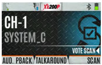

NOTE
If talkaround is enabled, Vote Scan is disabled until talkaround is disabled again.
5.14.4 Edit Scan List
Depending on the scan list options selected via RPM2, you may be able to add or remove channels/groups from the scan list.
To edit the scan list:
- Press the Menu/Select button.
- Press the left or right navigation buttons to display the SCAN menu.
- Press the up or down navigation buttons to select SCAN Lists.

- Press the up or down navigation buttons to highlight the scan list and press the Menu/Select button.
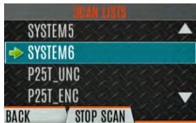
- Press the up or down navigation buttons to highlight channel/group.
- Select OPTIONS.
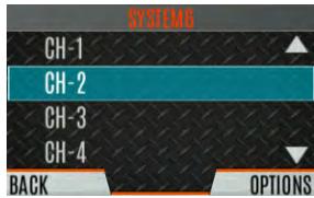
- Press the up or down navigation buttons to select ADD CHAN/DELETE CHAN, SET PRI1, SET PRI2, REMOVE PRI, or NUISANCE/Add BACK.
When a channel is not grayed out in the list, DELETE CHAN appears. When a channel/group is grayed out (not in list), ADD CHAN appears.
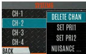
- Press the Menu/Select button to toggle selection.
5.14.5 Set or Remove Priority 1 and Priority 2 Channels
Priority channels are scanned more often than non-priority channels. Note that P1 and P2 can only be set if configured as "Keypad" and the scan list is not set to "Fixed" using RPM2.
To set or remove priority 1 and priority 2 channels:
- Press the Menu/Select button.
- Press the left or right navigation buttons to display the SCAN menu.
- Press the up or down navigation buttons to highlight SCAN Lists and press the Menu/Select button.
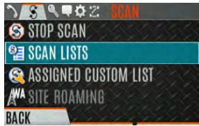
- Press the up or down navigation buttons to highlight the desired scan list and press the Menu/Select button.
- Press the up or down navigation buttons to highlight the desired channel/group.
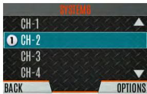
- Select OPTIONS.
- Press the up or down navigation buttons to highlight SET PRI1 or SET PRI2 and press the Menu/Select button. A Priority 1 channel appears with a P1; a Priority 2 channel appears with a P2.
- Select REMOVE PRI to remove priority.
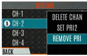
5.14.6 Custom Scan Lists
The Mixed Zone Scan (MZS) feature gives the user the capability to scan based on a custom scan list that is assigned at the system level. The Custom Scan (CS) list can contain System and Channel/Group configurations across P25 Trunked, P25 Conventional, and Analog Systems. When a Custom Scan List is assigned to a P25T system, the radio can scan P25T, P25C and Analog systems. When assigned to a P25C or Analog system, the radio only scans conventional channels. MZS also gives the user the capability to scan beyond the selected system group set.
P25T Scan
When a custom scan list is assigned to a P25T system, the user can scan P25T, P25C, and Analog groups/channels. All P25T systems must have the same WACN, System ID, and Unit ID to be added to the custom scan list. If P25C and/or analog channels are added to the custom scan list, the radio will scan them using the Trunked/Conventional scan feature described in section 5.14.2, and will override any other conventional scan list that may have been programmed using RPM2.
P25C and Analog Scan
When a custom scan list is assigned to a P25C or Analog System, the user can scan P25C and Analog channels. P25T systems are ignored.
Custom scan list can be created using RPM2 or at the radio. The radio supports up to 10 Custom Scan lists, with up to 100 channels/groups in each.
5.14.6.1 Create Custom Scan List
To create a custom scan list at the radio:
- Press the Menu/Select button.
- Press the left or right navigation buttons to display the SCAN menu.
- Press the up or down navigation buttons to highlight ASSIGNED CUSTOM LIST and press the Menu/Select button.
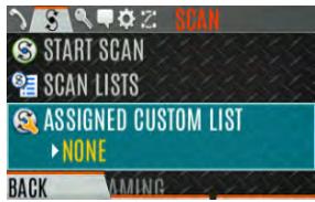
- Press the OPTIONS softkey.
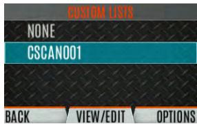
- Select ADD SCAN LIST.
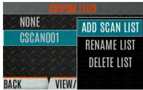
- Press the up or down navigation buttons to highlight the newly added scan list and press the VIEW/EDIT soft key.
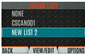
- Press the left or right navigation buttons to display the desired system.
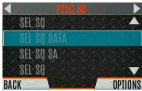
- Press the up or down navigation buttons to highlight the desired group/channel and press the OPTIONS softkey. From here, you can add/delete channels from the scan list and set/remove Priority 1 and Priority 2 channels.
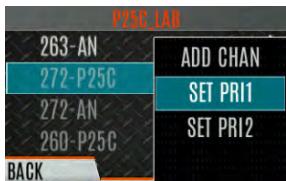

NOTE
When a custom scan list is selected, that list is scanned any time scanning is enabled for any Trunked, conventional, or P25 Conventional system. To scan only the channels assigned to a system, custom scanning must be turned off.
5.14.7 Wide Area System Scan (P25 Trunked and EDACS)
Wide Area System Scan (WASCAN) causes the radio to roam across mobile systems when the currently selected system's control channel is lost. The radio will scan the control channels of other systems.
To enable/disable Wide Area System Scan:
- Press the Menu/Select button to access the main menu.
- Press the left or right navigation buttons to display the SCAN menu.
- Press the up or down navigation buttons to highlight SITE ROAMING and press the Menu/Select button to toggle Wide Area System Scan ENABLED/DISABLED.
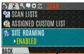
- Select BACK to exit the scan menu.
5.14.8 Site Lock
The Site Lock feature provides a list of available, adjacent sites that the user can lock the radio to. This restricts the radio from roaming between sites. Up to 512 sites can be programmed to the radio.

NOTE
Site Lock is only supported on P25 Trunked Systems with Enhanced CC Scan enabled. A button on the radio can be programmed to access the Site Alias list (see Section 6.5).
- Press the Menu/Select button to access the main menu.
- Press the left or right navigation buttons to display the SCAN menu.
- Press the up or down navigation buttons to highlight SITE ALIAS.
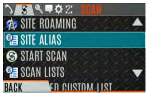
- Press the Menu/Select button to display the list of available sites. If a Site Alias is programmed for the available site(s), it is displayed here. Otherwise, the system name is displayed.
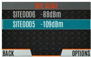
- From the OPTIONS menu, select LOCK SITE or SWITCH SITE.
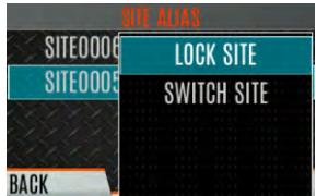
5.15 RADIO STATUS
The status feature allows the radio user to send a status condition to the site without making a voice call. There can be up to 10 status conditions programmed into the radio. For each status defined, there is an ID and an alphanumeric name. The ID is sent to the site and the alphanumeric name appears on the radio display when the ID corresponds with the information programmed at the site.

NOTE
A button on the radio can be programmed to send a radio status (see Section 6.5).
To send a radio status:
- Press the Menu/Select button to access the main menu.
- Press the left or right navigation buttons to display the MESSAGES menu.
- Press the up or down navigation buttons to highlight RADIO STATUS and press the Menu/Select button.
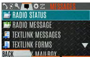
- Use the up or down navigation buttons and the Menu/Select button to highlight and select desired status.
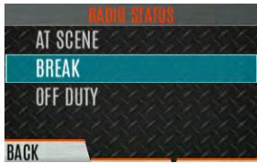
5.16 RADIOMESSAGE
The message feature is used to send a message to the site without making a voice call. There can be up to ten messages programmed into the radio. For each message defined, there is an ID and an alphanumeric name. The ID is sent to the site and the alphanumeric name appears on the radio display when the ID corresponds with the information programmed at the site.

NOTE
A button on the radio can be programmed to send a radio message (see Section 6.5).
To send a radio message:
- Press the Menu/Select button to access the main menu.
-
Press the left or right navigation buttons to display the MESSAGES menu.
-
Press the up or down navigation buttons to highlight RADIOMESSAGE and press the Menu/Select button.
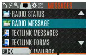
- Use the up or down navigation buttons and the Menu/Select button to highlight and select the desired message.
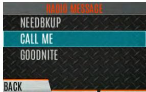
5.17 RADIO TEXTLINK
Radio TextLink provides short text messaging functionality for radios. Due to the difficulty of entering text messages on a radio, predefined "canned" messages and predefined replies can be stored in the radio. To facilitate sending messages where information must be provided at send time, text message forms can also be stored in the radio. A form can contain up to four text prompts, for which the operator enters alphanumeric values before sending the message.
5.17.1 RadioTextLinkMessages
To send a canned Radio TextLink message:
- Press the Menu/Select button to access the main menu.
- Press the left or right navigation buttons to display the MESSAGES menu.
- Press the up or down navigation buttons to highlight TEXTLINK MESSAGES and press the Menu/Select button.
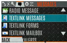
-
Press the left or right navigation buttons to display the desired message.
-
Press the Menu/Select button to send the message.
- Select CHG CALLEE to change the destination for the message.
- Select TOD QUERY to get the time of day.
5.17.2 RadioTextLinkForms
Form messages are displayed and stored in the radio as a message in which each field to be filled is indicated by a question mark (?) followed by one or more asterisks (^*) . The number of asterisks indicates the maximum number of alphanumeric characters allowed for that field.
To send a Radio TextLink form:
- Press the Menu/Select button to access the main menu.
- Press the left or right navigation buttons to display the MESSAGES menu.
- Press the up or down navigation buttons to highlight TEXTLINK FORMS and press the Menu/Select button.
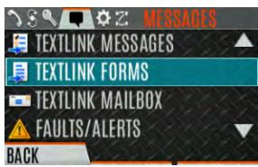
- Press the left or right navigation buttons to display the desired message and press the Menu/Select button.
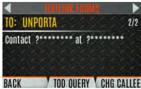
- Enter text into blank field(s) (up to eight alphanumeric characters). Press the NUMERIC softkey to toggle to the alternate function of the left, right, up, and down navigation buttons (select the numbers/letters assigned to that button). Press the NEXT soft key.
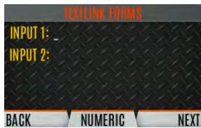
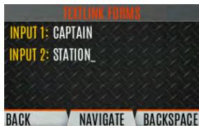
- Select SEND to send the message. Select CHG CALLEE to change the destination for the message. Select TOD QUERY to get the time of day.
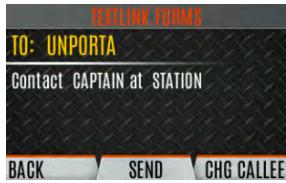
5.17.3 View Received Messages
When the icon appears on the idle display, there are Radio TextLink messages waiting to be read.
To view received Radio TextLink messages:
- Press the Menu/Select button to access the main menu.
-
Press the left or right navigation buttons to display the MESSAGES menu.
-
Press the up or down navigation buttons to highlight TEXTLINK MAILBOX and press the Menu/Select button. From the mailbox, select OPTIONS to delete messages, view details of messages, and reply to messages.
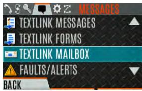
5.18 FAULTS/ALERTS
(1) is displayed on the idle display when there is a fault.
To view and clear faults/alerts:
- Press the Menu/Select button to access the main menu.
- Press the left or right navigation buttons to display the MESSAGES menu.
- Press the up or down navigation buttons to highlight FAULTS/ALERTS and press the Menu/Select button.
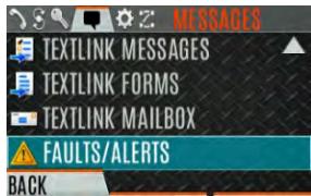
- Fault messages are displayed. Press the up or down navigation buttons to highlight the desired fault. Press the OPTIONS soft key delete faults. Press the DETAILS soft key to view details for the highlighted fault.
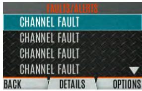
Possible faults include:
- BATTERY FAULT- Replace battery.
- EEEPROM FAULT - Contact L3Harris.
RF FAULT - Contact L3Harris. - OVERCURRENT - Check antenna and antenna connection. Try replacing antenna.
- INVALID SYSTEM - Feature not installed.
-
CHANNEL FAULT - Channel frequency programmed is not valid for this radio.
-
If you view but do not delete the fault, the alert icon goes away on the idle display.
-
Contact L3Harris for assistance with diagnosing a fault.
5.19 TONE ENCODE
Tone Encode is a generic tone encoding scheme for call identification when transmitting on a conventional system. It supports generic user-definable tone encode (up to 15 tones), Type 99 (up to 2 tones) and 5/1 Tone (up to 5 tones) encoding formats.
Tone encoding schemes are used to transmit calls to one or more target radios that have been programmed with the correct tone decode sequence. When the receiving radio detects its tone decode sequence, it unmutes on the call.
To select a Tone Encode option:
- Press the Menu/Select button to access the main menu.
- Press the left or right navigation buttons to display the CALL menu.
- Press the up or down navigation buttons to highlight TONE ENCODE and press the Menu/Select button.
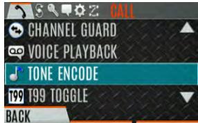
- Select the desired Tone Encode option from the list.
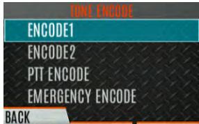
5.20 ENCRYPTION
Refer to Appendix C for instructions to configure encryption.
5.20.1 Zeroize Keys from Radio
It may be necessary to remove keys because of compromise or expiration.
To zeroize keys from the radio:
- Press the Menu/Select button to access the main menu.
- Press the left or right navigation buttons to display the SECURITY menu.
- Press the up or down navigation buttons highlight ZEROIze KEys and press the Menu/Select button.
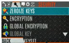
- Press the YES softkey to remove the keys. This will also remove the keysets.

5.20.2 Protected Keys
The Protected Keys feature transfers P25 Voice Keys, from L3Harris Key Loader to the radio, that have been wrapped (AES) or encrypted (DES) with Key Protection Keys (KPKs). KPKs are nothing more than unprotected Key Encryption Keys (KEKs). The KPKs need to be loaded into the radio before the Protected Keys are loaded. Once loaded into the radio, the KPKs are used to unwrap (AES) or decrypt (DES) the Protected Keys.
5.20.3 Global Encryption
Global Encryption can be enabled when encryption keys are loaded on the radio and the selected Zone/System is encrypted. When Global Encryption is enabled on the radio, a Global Key is used for all encrypted transmissions until:
- Global Encryption is disabled.
- A new personality is activated.
The active keyset is changed.
The system is changed.
Global Encryption behavior is available on all channels that support encrypted communications.
To enable Global Encryption and/or change Global Encryption Key:
- Press the Menu/Select button to access the main menu.
- Press the left or right navigation buttons to display the SECURITY menu.
- Press the up or down navigation buttons to highlight GLOBAL ENCRYPTION. Press the Menu/Select button.
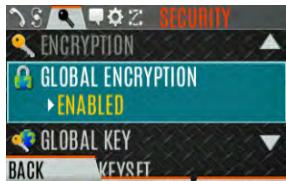
- Press the up or down navigation buttons to highlight the desired Global Key and press the Menu/Select button to enable Global Encryption.
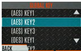
- To change the selected global key, press the up or down navigation buttons to highlight GLOBAL KEY on the SECURITY menu. Press the Menu/Select key.
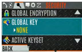
- Press the up or down navigation buttons to highlight the global key and press the Menu/Select button.
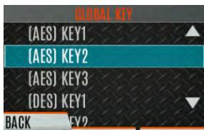
- RPM2 allows Key Numbers to be given Key Names.
- The optional global key icon is displayed on the main display.
5.20.4 Select Keyset
To select a keyset:
- Press the Menu/Select button to access the main menu.
- Press the left or right navigation buttons to display the SECURITY menu.
- Press the up or down navigation buttons to select ACTIVE KEYSET. Press the Menu/Select button to toggle to the inactive keyset.
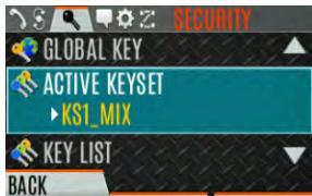
5.20.5 View Key List
To view the key list:
- Press the Menu/Select button to access the main menu.
- Press the left or right navigation buttons to display the SECURITY menu.
- Press the up or down navigation buttons to select KEY LIST and press the Menu/Select button.
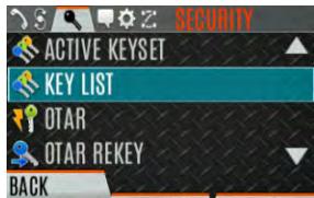
- The available key lists are displayed.
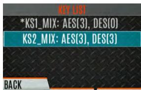
5.20.6 Delete Individual Keys
To delete individual keys from a keyset:
- Press the Menu/Select button to access the main menu.
- Press the left or right navigation buttons to display the SECURITY menu.
- Press the up or down navigation buttons to select KEY LIST and press the Menu/Select button.
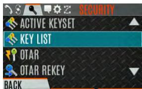
- The available key lists are displayed.
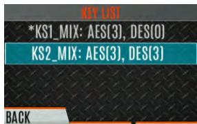
- Select the desired keyset and press the Menu/Select button to display the individual keys. Highlight the desired key and press the Delete softkey.
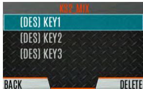
5.20.7 OTAR Configuration
OTAR is the over-the-air-rekeying from a KMF and must be enabled for the digital only channel using RPM2. For OTAR operation, the appropriate KEKs must be loaded into the radio using the L3Harris Key Loader or a KVL device.
The KMF Configuration must include the RSI of the KMF and the appropriate Message Number Period.
To enable OTAR and request rekey:
- Press the Menu/Select button to access the main menu.
-
Press the left or right navigation buttons to display the SECURITY menu.
-
Press the up or down navigation buttons to highlight OTAR and press the Menu/Select button to toggle ENABLED/DISABLED.
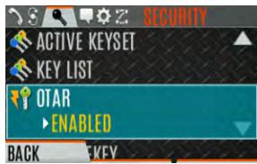
- Press the up or down navigation buttons to select OTAR REKEY and press the Menu/Select button to request that the KMF updates the keys in the radio. OTAR REKEY is only enabled if the radio has successfully registered for data operations. If enabled via programming, the radio plays an audible confirmation tone to indicate successful OTAR rekey.
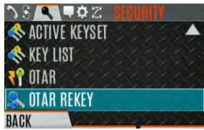
5.21 P25 CONVENTIONAL FALLBACK
When P25 Conventional Fallback is enabled, a P25 trunking site responds to failures by allowing one or more channels to operate as conventional repeaters. Terminals which are properly configured can then communicate using the conventional P25 channel(s).
The radio provides an audible and visual indication when operating in P25 Conventional Feedback.
5.22 EMERGENCY CHECK-IN TIMER
The Emergency Check In Timer is an added safety feature for a radio user who may be in a dangerous environment. If this timer expires before being cancelled by the radio operator, an emergency is declared.
To enable the Emergency-Check In Timer via the radio menu:
- Press the Menu/Select button to access the main menu.
- Press the left or right navigation buttons to display the CALL menu.
- Press the up or down navigation buttons to highlight EMERGENCY TIMER and press the Menu/Select button.
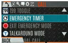
- Set the Emergency Check-In Timer using the left or right navigation buttons. The minimum and maximum allowable values are programmed via RPM2. Default is 10 minutes.

- Press START to restart the timer or STOP to stop the timer and return to the CALL menu. If enabled via RPM2, pressing the PTT button will also restart the timer.


NOTE
Power cycling the radio will stop the Emergency Check-In Timer.
If the EMERGENCY TIMER menu is not available to the radio user, a button can be programmed to enable/disable the Emergency Check-In Timer. In this case, the timer value is set in RPM2 and cannot be changed at the radio.
6. PROGRAMMING
This section provides information on front panel programming. Programming can also be accomplished by creating a plan using a computer with RPM2 installed.
6.1 L3HARRIS DEVICE MANAGEMENT
L3Harris Device Management is a web-based application that allows the user to collect basic status and version information, read and program personalities, and program firmware in XL radios over secure Wi-Fi. Refer to L3Harris Device Management User's Manual 14221-2100-2010 for information about using the application.
The radio only communicates with L3Harris Device Management when initiated by the user as shown in the following steps:
- From the radio menu select UTILITY DEVICE MANAGEMENT.
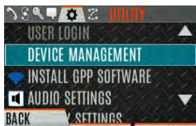
- Verify the CONNECTION STATUS is CONNECTED.
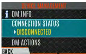
- Highlight and select DM ACTIONS to check for available updates.
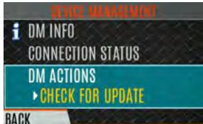
- The DM ACTIONS menu displays CHECKING while searching for updates. This will change to UPDATE AVAILABLE if there are available updates.
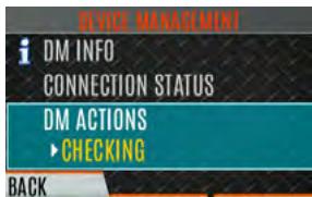
- Select DOWNLOAD & INSTALL to install available updates.
6.2 PROGRAMMING VIA RPM2
Radio Personality Manager2 (RPM2) is used to program the XL portable. With RPM2, you can fully program the radio using cable 14051-0410-A1.

Removing power during radio programming or programming the radio with low battery power could corrupt installation of firmware.

Ensure that the radio is turned off before connecting the programming cable. After the cable is connected, then power on the radio.
6.3 EDIT CHANNEL (ANALOG AND P25 CONVENTIONAL ONLY)
Channels can be edited from the Channel Information (CH INFO) menu display. Most of the displayed channel parameters can be modified here. Channel edits persist across a power cycle. Loading a personality clears any channel edits. Available parameters vary depending on whether the channel is a P25 or analog channel. The Channel Information (CH INFO) menu display is only available if a Channel Edit Password has been programmed via RPM2.
To edit a channel:
- From the main display, press to access the CH INFO screen.
- Press the up or down navigation buttons to scroll through the programmed channel settings.
- Press the EDIT soft key.
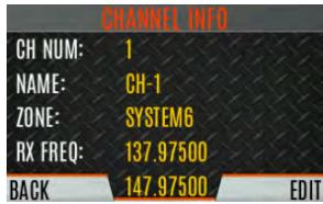

Only authorized users should attempt channel editing.
- Enter the password programmed via RPM2. You do not have to re-enter the password until you power cycle the radio.
- Press the ENTER soft key.
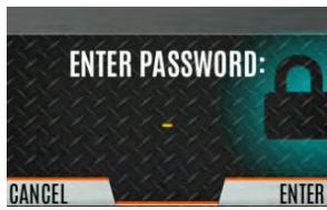
-
Highlight and select the parameter to edit. For P25 channels, modify remaining channel settings:
-
CHANNEL NAME - The Channel Name cannot be changed from this screen; RPM2 is required to change the Channel Name.
- RX FREQUENCY - Receive frequency. Note that if the new frequency is invalid, the display reverts to the old frequency (Table 6-1).
TX FREQUENCY - Transmit frequency.
TX POWER - Transmit power. Toggle between LOW and HIGH. - TALKGROUP - Select a talkgroup for the channel. Talkgroup name cannot be set here.
- RX NAC - Network Access Code (NAC) radio uses for Normal squelch in receive.
TX NAC - NAC radio transmits to break Normal squelch on receiving radio.
P25 SQUELCH - Select type the radio uses in receive. Select NORMAL, SELECTIVE, or MONITOR. - RX CHAN GUARD – Squelch type radio uses in receive. Select Noise, CTCSS, or CDCSS. For a digital channel, the RX CHAN GUARD is used to receive from a Conventional analog channel that is on the same frequency and uses the selected Channel Guard.
RX CODE - Code radio looks to unmute the speaker on the receiving radio when CDCSS squelch is used in conventional mode.
RX TONE - Tone radio looks to unmute the speaker on the receiving radio when CTCSS squelch is used in conventional mode.
-
For analog channel, modify remaining channel settings:
-
CHANNEL NAME - The Channel Name cannot be changed from this screen; RPM2 is required to change the Channel Name.
TX FREQUENCY - Transmit frequency.
TX POWER - Transmit power. Toggle between HIGH and LOW. - RX CHAN GUARD - Squelch type radio uses in receive. Select Noise, CTCSS, or CDCSS.
RX TONE - Tone radio uses to break selective squelch on receiving radio. This is available when RX squelch is set to CTCSS.
RX CODE - Code radio uses to break selective squelch on receiving radio. This is available when RX squelch is set to CDCSS.

NOTE
RX CHAN GUARD is not available on this screen if it was enabled from the CALL menu as per Section 4.21.
- TX CHAN GUARD - Squelch type radio uses in transmit. Select None, CTCSS, or CDCSS.
TX TONE - Tone sent by transmitting radio to allow receiving radio to unmute when CTCSS squelch is used in conventional mode.
TX CODE - Code sent by transmitting radio to allow receiving radio to unmute when CDCSS squelch is used in conventional mode.

NOTE
TX CHAN GUARD is not available on this screen if it was enabled from the CALL menu as per Section 4.21.
- An asterisk is displayed in front of the CHANNEL label on the main display when a channel has been edited. The asterisk is NOT shown for TX Power or Talkgroup changes.

NOTE
When the only item edited is the TX or RX CHAN GUARD values, and then CHAN GUARD edit is Disabled, the asterisk goes away and the channel is no longer considered edited. This is the only editable item for which this is true.
Table 6-1: Valid Frequency Ranges
| INTERNATIONAL (NON-REBANDED) | US (REBANDED) | FREQUENCY RESOLUTION |
| 763 - 776 MHz | 768 - 776 MHz | 6250 kHz |
| 793 - 806 MHz | 798 - 806 MHz | 6250 kHz |
| 806 - 825 MHz | 806 -816 MHz | 6250 kHz |
| 851 - 870 MHz | 851 - 861 MHz | 6250 kHz |
6.4 OTAP
The radio supports Over-the-Air-Programming (OTAP) via ProFile Manager. RPM2 creates, modifies and stores personality information while ProFile Manager delivers the personality over the network to the desired radios. ProFile Manager also contains the ability to read personality information over-the-air and save the files, so that RPM2 can modify the information if necessary.
You can interrupt the programming process, if necessary, by depressing the Push-to-Talk (PTT) button or declaring an emergency. Once a radio personality update is successfully completed, the radio automatically resets itself, switches to the new personality, and returns to normal operation. For more information on using ProFile Manager, refer to software release notes 14221-1100-8250.
6.5 PROGRAMMABLE BUTTONS AND SWITCHES
6.5.1 Programmable Buttons
Press the down navigation button while on the main display to view the functions assigned to the programmable buttons. The programmable buttons are programmed using RPM2. A delay of 0 to 10 seconds can be defined using RPM2 for the programmable buttons. Table 6-2 lists and describes the functions that can be programmed to the buttons:
Table 6-2: Programmable Button Options
| FUNCTION | DESCRIPTION |
| No Operation | |
| Adjust Squelch | Allows the user to adjust the analog squelch level using the 4/Left and 6/Right buttons. |
| Audio Playback | Accesses the AUDIO PLAYBACK menu. See Section 4.27. |
| Bluetooth Enable/Disable | Enable/disable Bluetooth. See Section 5.10. |
| Button Info | Opens the Programmable Button Info Menu. Button Info is assigned to the Key Down button by default. |
| Caller ID | Opens the Caller ID menu. When a Missed Call Alert is shown on the radio display, pressing the Key Up button on the radio opens the CALLER ID menu irrespective of the functionality assigned to the Key Up button. |
| Channel Guard Override | Allow user to pick a different Channel Guard setting for the current channel. |
| CMD Mute | Mutes all audio. Audio remains muted until this button is pushed again or until an I-Call is received by the radio. |
| Direct System/Zone Entry | Allow user to select system/zone. |
| Drop Call | Drop or terminate any group call that the radio receives. |
| Editable Preset | When this button is pressed and held for four (4) seconds, the radio saves the currently selected system/group or zone/channel to this button. When this button is pressed and released in less than four (4) seconds, the radio changes to the user-saved system/group or zone/channel if already saved by the user. If system/group or zone/channel is not configured for this button, when user defined preset button is pressed and released in less than four (4) seconds, the radio displays “Preset Empty.” |
| Emergency Check In Timer | When this button is pressed, the Emergency Check In Timer is activated. See Section 5.22 for more information. |
| Fixed Preset | When this button is pressed and released, the radio changes to the system/group or zone/channel specified in RPM2. |
| Flashlight Mode | Press and hold to turn on the front and top display backlights. Release the button to turn off both displays. |
| Front Backlight | Toggles front display's backlight On/Off/Momentary. |
| Home | Goes to home channel. |
| Individual Call | Initiate an Individual Call. |
| Lock Keypad | Locks the DTMF keypad, programmable function keys and navigation keys. |
| Monitor Toggle | Toggles Monitor On/Off. |
| Monitor/Clear | Temporarily turn off selected squelch to monitor for traffic that may not normally break squelch. Also, press this button followed by the emergency button to clear an emergency. |
| Noise Cancellation Enable/Disable | Turns Noise Cancellation On/Off. |
| Nuisance Delete | Performs a Nuisance Delete. See Section 4.31 for more information. |
| Numeric Channel Entry | Allows number channel entry. |
| OTAR Rekey | Initiate an OTAR rekey. See Section 5.20.6. |
| Phone Call | Initiate a telephone interconnect call. See Section 4.25. |
| Profile Toggle | Toggles between the currently active profile (if one has been selected) and no profile. |
| Priority Talk Group | Assigns Priority Talk Group functionality in trunked systems. Assigns the button to UNASSIGNED and plays boop tone in Conventional systems. |
| Scan Enable | Enable/disable scan. |
| Secure Enable Toggle | Toggles Encryption Mode On/Off. See Sections 4.19 and 5.20 for information on Encryption. |
| Send Message | Sends a preconfigured message. See Section 5.16 for more information. |
| Send Status | Sends a preconfigured status. See Section 5.15 for more information. |
| Site Alias | Accesses the Site Alias list. See Section 5.14.8 for more information. |
| Site Roaming | Enable/disable Site roaming. Site Roaming allows the radio to roam to another site. |
| Speaker Mute Toggle | Toggles Speaker Muted/Unmuted. |
| Stealth Mode | Enable/disable Stealth Mode. See Section 4.36. |
| System Down | Scrolls down through the list of available systems, stopping when the end of the list is reached. |
| System Down Wrap | Scrolls down through the list of available systems, wrapping to the top when the bottom of the list is reached. |
| System Up | Scrolls up through the list of available systems, stopping at the top of the list. |
| System Up Wrap | Scrolls up through the list of available systems, wrapping to the end when the beginning of the list is reached. |
| Talkaround | Toggles talkaround On/Off. See Section 4.22. |
| TX Power High/Low | Toggle TX Power between LOW and HIGH. |
| View SA Display | Displays the Situational Awareness (SA) Screen. See Section 5.2. |
| Voice Announce | Enable/disable Voice Annunciation. See Section 4.18. |
| Zone Down | Scrolls down through the list of available mixed system zones, stopping when the end of the list is reached. If no mixed system zones are defined, or there is only one, the user will hear a deny tone when the button is pressed. |
| Zone Down Wrap | Scrolls down through the list of available mixed system zones, wrapping to the top when the bottom of the list is reached. If no mixed system zones are defined, or there is only one, the user will hear a deny tone when the button is pressed. |
| Zone Up | Scrolls up through the list of available mixed system zones, stopping at the top of the list. If no mixed system zones are defined, or there is only one, the user will hear a deny tone when the button is pressed. |
| Zone Up Wrap | Scrolls up through the list of available mixed system zones, wrapping to the end when the beginning of the list is reached. If no mixed system zones are defined, or there is only one, the user will hear a deny tone when the button is pressed. |
| WifiAP | Enables/disables the Wi-Fi AP in XL-Radios that include the LTE option. |
6.5.2 Programmable A/B/C Switch
Sections 6.5.2.1 and 6.5.2.2 describe the various functions that can be programmed to the A/B/C switch.
6.5.2.1 Single-Instance Features
Single-instance features can only be assigned to one switch position at a time. If one of these features is programmed to the A/B/C switch, other means of accessing that feature are disabled (i.e., programmable buttons, call menu, etc.).
Table 6-3: Single-Instance Features
| FUNCTION | DESCRIPTION |
| No Function | No function programmed to switch. |
| Talkaround | See Section 4.22. |
| Scan | Enables scanning. |
| Bluetooth | Enable Bluetooth. |
| TX Power High | Sets transmission power level to High. • Changing to a Tx Power High position overrides the current personality or user setting for TX Power. • Changing from a Tx Power High position restores the personality-configured Tx Power Level. |
| TX Power Low | Sets transmission power level to Low. • Changing to a Tx Power Low position overrides the current personality or user setting for TX Power. • Changing from a Tx Power Low position restores the personality-configured Tx Power Level. |
| Keypad Lock | Locks DTMF, programmable, and navigation soft keys. |
| Radio Lock | When set, prevents the radio software from responding to the following physical inputs on the radio: • Volume Knob Change (power off is not prevented) • Channel Knob • Side User-Programmable Buttons and Keypad (DTMF, programmable, and navigation/soft keys) Exception is the emergency button and if any key is programmed for Monitor/Clear, it can be used with the emergency button to clear emergency, if so programmed. |
| Channel Bank | Selects channels 1-16 in position A; 17-32 in position B; and 33-48 in position C. If Channel Bank is selected for any single position, all 3 positions (A, B, and C) will be set to Channel Bank. |
6.5.2.2 Indexed Features
These features can be assigned to any number of positions if each index value selected for it is unique across multiple assignments of the same feature; for example, you cannot assign a Zone with an index (e.g., “ZONE A”) to both positions A and B.
Table 6-4: Indexed Features
| FUNCTION | DESCRIPTION |
| Zone Selection | Sets to the Zone index value. ·When setting the A/B/C switch to an indexed zone assigned position, the radio sets, but does not “hold,” that zone. This has the resulting effects: >This sets the channel knob to be zone-based system/channel selection just like selecting a zone from the main “Zone” menu or ramping up/down using the side user-programmable buttons. >If a user then changes to a different system or zone via another method (menu, button, etc.), it will override the Zone selection switch setting accordingly and not require it to remain in the zone where the switch assignment is set. ·When changing away from a Zone assigned position, no actions/changes will be taken by the radio. |
| System Selection | Sets to the System index value. ·When setting the A/B/C switch to an indexed System assigned position, the radio sets, but does not “hold,” that System. This has the resulting effects: >This sets the channel knob to be system-based channel selection, just like selecting a system from the main “Zone” menu or ramping up/down using the side user-programmable buttons. >If a user then changes to a different system or zone via another method (menu, button, etc.), it will override the System selection switch setting accordingly and not require it to remain in the system where the switch assignment is set. ·When changing away from a System assigned position, no actions/changes will be taken by the radio. |
6.6 PROGRAMMABLE ICONS
6.6.1 Top Display
The top display has space for up to seven configurable icons, which can be programmed to display any of the following:
Blank
Signal Strength
- Battery Status
- Bluetooth enabled
- Encryption enabled
- Scan/Vote Scan enabled
- Talkaround enabled
Emergency mode active
Wi-Fi
6.6.2 Front Display
The front display has space for up to 10 configurable icons, which can be programmed to display any of the following:
- Blank
Signal Strength - Battery Status
- Bluetooth enabled
- Encryption enabled
- Global Encryption
- Talkaround enabled
TX Disabled
Tones Disabled - PTT Disabled
- Speaker Muted
Monitor - OTAR Status (Disabled, Registering, Registered, Rekeying)
TX Power level (Low/High/RX Only)
GPS Status
VDOC
- Failsoft
- Data Status (TX/RX)
Alert(s)
RX Mail
- Noise Cancellation Enabled
- Type 99 Enabled
- Conventional Site Status (Unregistered/Registered)
Wi-Fi
Wi-Fi AP
7. NARROWBANDING
The FCC has mandated that all public safety radios manufactured after January 1, 2013 comply with narrowbanding restrictions. Radios manufactured after the above date will comply with these restrictions. Existing radio personalities that contain frequencies that violate these FCC rules will cause an invalid channel error indication on the radio display. The user must change the radio personality to comply with the rules. Note that there are multiple exceptions to the narrowbanding mandate.
8. GLOSSARY
-A-
AES Advanced Encryption Standard
AES-256 Advanced Encryption Standard, 256-bit
AMBE+2 Advanced Multi-Band Excitation implementation 2
ANSI American National Standards Institute
ASCII American Standard Code for Information Interchange
-B-
-C-
Celsius
CA Canada
CDCSS Continuous Digital Coded Squelch System
CH INFO Channel Information
CKR Common Key References
CMB Continuous Marine Broadcast
CTCSS Continuous Tone Coded Squelch System
-D-
DES Digital Encryption Standard
DES-OFB Digital Encryption Standard Output Feedback
DFO Department Fisheries Ocean
DMS Degrees Minutes Seconds
-E-
EPIRB Emergency Position-Indicating Radio Beacons
-F-
F Fahrenheit
FCC Federal Communications Commission
FM Frequency Modulation
-G-
GHz Giga (10^9) Hertz
GEOTRANS Geographic Translator
GPS Global Positioning System
-H-
Hz Hertz
HKL Harris Key Loader
-1
ID Identification
IEEE Institute of Electrical & Electronics Engineers
INTL International
-J
| -KEK | Key Encryption Key |
| kHz | kilo (103) Hertz |
| KID | Key Identification |
| KMF | Key Management Facility |
| KMS | Key Management System |
| KS | Key Set |
| KVL | Key Variable Loader (Motorola KVL Device) |
| -L- | |
| LAT/LONG DMS | Latitude/Longitude Degrees Minutes Seconds |
| LAT LONG DD | Latitude/Longitude Decimal Degrees |
| LED | Light Emitting Diode |
| Li-ION | Lithium-ION |
| -M- | |
| MHz | Megahertz |
| mm | Millimeter |
| MR | Mobile Radio |
| ms | milli (10-3) seconds |
| -N- | |
| NAC | Network Access Code |
| Ni-MH | Nickel Metal Hydride |
| NOAA | National Oceanic and Atmospheric Administration |
| -O- | |
| OET | Office of Engineering and Technology |
| OTAR | Over-The-Air Rekey |
| -P- | |
| P25 | Project 25 |
| POS | Position |
| PRI | Priority (Channel) |
| PTT | Push-to-Talk |
| -Q- | |
| -R- | |
| RF | Radio Frequency |
| RPM2 | Radio Personality Manager 2 |
| RSI | Radio Set Identifier |
| RSM | Remote Speaker Microphone |
| RX | Receive |
| -S- | |
| SA | Situational Awareness |
| SMA | Subminiature Version A |
| -T- | |
| TIA | Telecommunications Industry Association |
TX Transmit
-U-
UHF Ultra High Frequency
UKEK Unique Key Encryption Key
US United States
USCG United States Coast Guard
UTC Universal Time Coordinated
UTM Universal Transverse Mercator
-V-
VDC Volts, Direct Current
VHF Very High Frequency
VIDA Voice Interoperability Data Access
VTS Vessel Traffic Service
-W-
WEEE Waste from Electric and Electronic Equipment
-X-
-Y-
-z-
9. BASIC TROUBLESHOOTING
When installing XLP radio software, if the upgrade is interrupted by a power cycle, the radio displays . This indicates a partial install occurred and a reinstall is required. The radio should be connected via the programming cable and the software should be installed again.
If is displayed, the radio has lost its factory information and must be returned for updating.
9.1 ERROR MESSAGES
This section provides a list of error messages, as well as possible causes and solutions.
Table 9-1: Displayed Error Messages, Reasons, and Resolutions
| SCREEN/MENU | DISPLAYEDERRORMESSAGE | REASON | RESOLUTION |
| Top-LevelScreen | INVALID KEYSTOREZEROIZE NEEDED | Corrupt key database orincorrect databaseconfiguration. | Zeroize database. |
| BluetoothPairingScreen | PAIRING_FAILED | Bluetooth pairing failed. | Ensure device is discoverable and attemptto re-pair the device. |
| Channel EditScreen | EDIT_FAILED | Unable to modify P25Channel. | Power cycle and try again--contactL3Harris if problem persists. |
| Channel EditScreen | INVALID RX FREQUENCY | Entered Rx frequency isinvalid. | Ensure frequency follows band spacingrules. |
| Channel EditScreen | INVALID TX FREQUENCY | Entered Tx frequency isinvalid. | Ensure frequency follows band spacingrules. |
| InstallOperations | INSTALL_FAILED | Error during install process. | Transfer file again and reattempt install.Contact L3Harris if problem persists. |
| InstallOperations | INSTALL_FAILED | Extraction of compressed filefailed. | Transfer file again and reattempt install.Contact L3Harris if problem persists. |
| InstallOperations | INSTALL_FAILED | Removal of existing SWfailed. | Attempt install again and contact L3Harrisif problem persists. |
| Mission PlanIn ProgressScreen | Mission plan activation failed. | Use RPM2 to ensure plan validity.Contact L3Harris if failures persist. | |
| Security Menu | ZEROIZE_FAILED | Radio could not zeroize. | Radio problem-power cycle and contactL3Harris if problem persists. |
| Security Menu | NO KEYS TO ZEROIZE | Key database empty. | Nothing to zeroize. |
| UtilitiesMenu | INCORRECT PASSWORD | Maintenance passwordinvalid. | Enter valid maintenance password. |
| Channel InfoScreen | INCORRECT PASSWORD | Channel edit passwordinvalid. | Enter valid channel edit password. |
| Top-LevelScreen | USER REGISTRATIONFAILED FOR... | The user has either entered the wrong values or the user is not in the UAS database. | Check the System ID and User ID. If they are correct, contact your network administrator. |
| Top-LevelScreen | USER PASSWORDFAILEDFOR... | The user has entered a different password then what is in the UAS when password is required. | Re-enter the password. If the error persists, contact your network administrator. |
| Top-LevelScreen | RADIO ESN INVALID FOR... | Contact your network administrator. | |
| Top-LevelScreen | EXCEED ALLOWED USERSFOR... | There are already three radios registered with the same User ID. | Turn off one of these radios or register with a different ID. |
| Top-LevelScreen | PROVISIONING Failed | This failure could be due to bad password or a network issue. | Re-enter the password. If the error persists, contact your network administrator. |
9.2 OTAR ERRORS/INFORMATION
WORKAROUNDS:
- Zeroize.
- Load proper KEK from the L3Harris Key Loader or Motorola KVL.
IF RADIO INDICATES:
- INVALID KEYSTORE ZEROIZE NEEDED - This occurs if the radio's keys were loaded by the L3Harris Key Loader followed by an attempt to load UKEKs with the Key Loader or keys with the Motorola KVL.
Fix by performing workaround 1, followed by 2.
- NO UKEK - Displayed during a zeroize performed from the radio or a zeroize initiated from the KMF.
Fix by performing workaround 2.
- Zeroize Complete - KMF has zeroized the radio.
Fix by performing workaround 2.
- Disabled OTAR Icon (red slash) - OTAR is disabled while in scan, talkaround, emergency, and monitor.
Fix by disabling these features. Icon will be corrected (no red slash).
- Gray OTAR Icon (no red slash) - OTAR has not registered with tower (Conventional or Trunked system).
Fix by verifying proper frequencies.
-
If the radio is turned to the OTAR channel out of range of a conventional tower, and then comes in range after 3 minutes, fix by issuing an OTAR. Rekey, leaving and re-enter the OTAR channel.
-
Green OTAR Icon - OTAR is registered, all is well.
-
If update fails, verify you are in range of the tower and the KEK is correct.
-
Blue OTAR Icon - OTAR is attempting to rekey.
-
If rekey fails, verify you are in range of the tower and the KEK is correct.
10. TECHNICAL ASSISTANCE
The Technical Assistance Center's (TAC) resources are available to help with overall system operation, maintenance, upgrades and product support. TAC is the point of contact when answers are needed to technical questions.
Product specialists, with detailed knowledge of product operation, maintenance and repair provide technical support via a toll-free (in North America) telephone number. Support is also available through mail, fax and e-mail.
For more information about technical assistance services, contact your sales representative, or contact the Technical Assistance Center directly:
North America: 1-800-528-7711
International: 1-434-385-2400
Fax: 1-434-455-6712
E-mail: PSPC_tac@l3harris.com
11. WARRANTY
Please register this product within 10 days of purchase. Registration validates the warranty coverage and enables L3Harris to contact you in case of any safety notifications issued for this product.
Registration can be made on-line at the Customer Care center webpage:
https://www.l3harris.com/all-capabilities/pspc-customer-care
While on the webpage, please review the applicable battery and/or product warranty literature.
APPENDIX A WI-FI PROGRAMMING

CAUTION
Due to numerous issues with discovering and programming radios connected to Enterprise Wireless networks, it is strongly suggested that a single Access Point Wireless network be used for programming radios with RPM2. See Section A.7 for more information.

CAUTION
ISED restricts 5150-5250 MHz to indoor use only.

NOTE
These instructions assume the user has a basic familiarity with Wireless (Wi-Fi) networks, their configuration, and how to connect devices. If you are unfamiliar with the terms and/or procedures mentioned in these instructions, please contact your IT department for help before attempting to configure Wi-Fi programming.

NOTE
For radios to be discoverable on the Wi-Fi network, your wireless router must be configured to allow Multicast (mDNS). This varies by router manufacturer; refer to your router's documentation for specific settings needed to enable Multicast (mDNS).
A.1 OVERVIEW
Perform the following to program a radio over Wi-Fi. For first time setup, see Section A.8.1.
- Configure the Access Point (Section A.2).
- Configure the personality (Section A.3).
- Configure the RPM2 application (Section A.4).
- Put the radio in Wi-Fi Programming Mode (Section A.5).
- Discovery and programming in the RPM2 application (Section A.6).
- Support for Enterprise Wireless Networks (Section A.7).
- Helpful Hints (Section A.8).
A.2 CONFIGURE THE ACCESS POINT
- Setup an Access Point (wireless router) as follows. The bold values provided below are the default values in the personality.
Wireless Networking Name (SSID): harrisradios
Shared Key (Network Password): password
Wireless Authentication/Security Mode (Encryption Type): WPA
WPA and WPA2-PSK are the available Encryption Types in the RPM2 application
- Ensure that the Access Point has Multicast (mDNS) enabled. See the second note at the top of Appendix A for more information.
A.3 CONFIGURE THE PERSONALITY
For a radio to be programmed over Wi-Fi, the active personality on the radio must be configured for connecting with the values that were set in Section A.2. The following steps detail how to configure an existing radio personality.
- In the personality, navigate to OPTIONS Network Configuration.
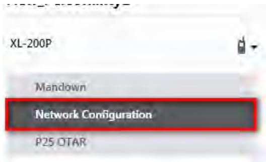
Figure A-1: Options Network Configuration
- Under the Wi-Fi Configuration section, set the Encryption Type, Network (SSID), and Network Password.

NOTE
XL radios support up to 24 different Wi-Fi networks (SSIDs). These 24 Wi-Fi networks are considered radio administrator approved and Trusted Wi-Fi Networks (TWiN) on which the radios can operate.
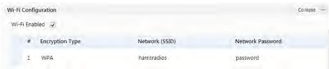
Figure A-2: Wi-Fi Configuration
- Under Network Service Configuration, the default values can remain the same. If the wireless network is managed by another department, please coordinate with them to get it setup correctly.
The Network Discovery Configuration Service Name is a Unique name used by RPM2 and radios to communicate with each other. There is more information about this in Section A.8.2.
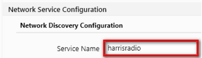
Figure A-3: Service Name
- After the personality is configured and saved, write it to the radio and then activate it.
A.4 CONFIGURE THE RPM2 APPLICATION
To ensure that RPM2 can discover radios over Wi-Fi, ensure that the Enable Wi-Fi checkbox is checked on the RPM2 Preferences screen as shown in Figure A-4. This checkbox is unchecked by default.
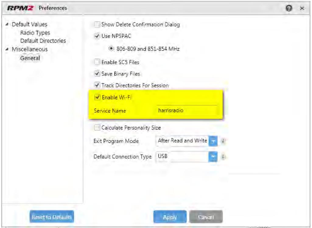
Figure A-4: Enable Wi-Fi in RPM2
Also, as shown in Figure A-4, the Service Name must be updated to reference the value in the active personalities for the radios you need to discover. See #3 in Section A.3 and Section A.8.2 for more information.
For default operation using the network as described in Section A.2, no other configuration of the radio or RPM2 is required.
A.5 PUT THE RADIO IN WI-FI PROGRAMMING MODE
To put the radio in Wi-Fi programming mode:
- Turn the radio off and remove the programming cable (optional).
- Press and hold the middle side button and PTT button (see Figure 5-1).
- Power on the radio while continuing to hold the buttons.
- Release the buttons when the WIFI INSTALL ACTIVE screen appears on the radio.
- Initially, the radio displays DISCONNECTED. When the IP address is displayed, the radio is available to be programmed.

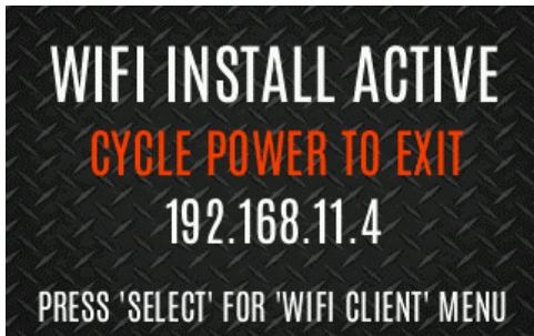
Figure A-5: Enable Wi-Fi Programming Mode on Radio

Refer to Section 4.35 for Wi-Fi Client selection information.
A.6 DISCOVERY AND PROGRAMMING IN THE RPM2 APPLICATION
- Start RPM2.
- Disconnect the radio from the programming cable.
- Select the Radio tab and click the Wi-Fi connection button
- When the Wi-Fi connection button is pressed, a "Discovering Wi-Fi Radios" message is displayed for several seconds and the radios connected to that access point with that Service Name populate the connection list.

To connect over Wi-Fi, the currently active personality MUST have the correct Wi-Fi parameters. Therefore, care must be taken that all personalities on a given radio have the correct Wi-Fi parameters for the desired network. Otherwise, activation of another personality on the radio will result in the inability to establish a Wi-Fi connection.
- Select a radio or radios and perform the desired action. Only Read Personality, Write Personality, and Load Code are supported over Wi-Fi. See the table below for the supported combinations.
Table 11-1: Wi-Fi Feature Support
| SINGLE RADIO | MULTIPLE RADIOS (UP TO 16) | |
| Read Single Personality | Yes | No |
| Read Multiple Personalities | Yes | No |
| Write Single Personality | Yes | Yes |
| Write Multiple Personalities | No | No |
| Load Single Code File | Yes | Yes |
| Load Multiple Code Files | Yes | Yes |
| Voice Annunciation | No | No |
| Feature Data | Yes | Yes |
| Radio Name | Yes | No |
| Install Splash Screen | Yes | Yes |
- In the Status Panel, all Wi-Fi related actions will have the prefix of "WIFI."
To help in displaying the radios, the "Connection" and "IP Address" columns are sortable.

NOTE
If the Access Point is not configured to the default values from Section A.2 and the active personality in the radio is removed, the radio loses connection to the Access Point and must be connected via the programming cable to write/activate a personality to reconnect to the Access Point.
A.7 RPM2 WI-FI SUPPORT FOR ENTERPRISE NETWORKS.
Enterprise Networks have certain limitations when it comes to Discovering/Programming Radios in RPM2. There is a 4500 second (75 minute) caching affect inherent to implementation with the Cisco® Wi-Fi solution that utilizes the Access Point (AP)/Wireless LAN Controller (WLC) components. Radios remain 'seen' in RPM2 even after the radio leaves Wi-Fi or is turned off. It is cached in RPM2 for 4500 seconds. This issue has only been observed with the Cisco AP and WLC solution; however, other enterprise wireless solutions may observe this caching affect. Operation with a lower tiered Wi-Fi router that does not operate with a WLC will likely not observe this behavior. Please see the Software Release Notes for Media Kit SK-019007-001 (14221-3100-8110) for more information.
A.8 HELPFUL HINTS
A.8.1 Initial Setup and Configuration
Since radio discovery is dependent on if Multicast (mDNS) messages are being received by RPM2, it is best to keep things as simple as possible. Here are the suggested steps if this is being setup and configured for the first time.
- Configure the Access Point with the default personality values provided in Section A.2.
- Create a basic personality with a single system, set and channel, write it to the radio and activate it.
- Complete Sections A.4 through A.6.
If the radio was not discovered in RPM2 but an IP address is displayed on the radio screen as seen in Figure A-5, this may mean that the Multicast (mDNS) messages are not making it through the Access Point. Consult the Access Point's manual and make sure that those messages are not being filtered out.
A.8.2 Grouping Radios by Service Name
One benefit of using a unique Service Name is that it allows the user to create logical groupings of radios to reduce the number of radios discovered in RPM2 and help reduce the overhead of keeping track of which radios have been configured.
For example, if there are 100 radios in Wi-Fi programming mode (see Section A.5) with the same Service Name, all 100 radios are displayed in the Radio tab after discovery has been completed. This makes it difficult to select and program multiple radios simultaneously. However, if the Service Name in the active personality on 16 of the radios are set to something unique like "fire1" and the RPM2 application Service Name (see Section A.4) is also updated to "fire1," only those radios with a Service Name of "fire1" are discovered and displayed in the Radio tab.
APPENDIX B SCBA BLUETOOTH CONFIGURATION

NOTE
Refer to the vendor documentation for your SCBA for device-specific programming and configuration instructions.
This appendix provides radio configuration instructions to enable Bluetooth pairing with SCBA.
Refer to RPM2 User's Manual 14221-1100-2060 as necessary when performing the steps in this section.
- Open RPM2.
- Ensure a Radio Name is programmed.
a. Select the Radio Tab Personality Tab.
b. Click the button and enter the radio name. The radio name can be up to 16 characters long.
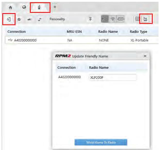
- Select Audio Settings from the Personality Rail.
- Under Audio Menu Settings, ensure Speaker is checked.
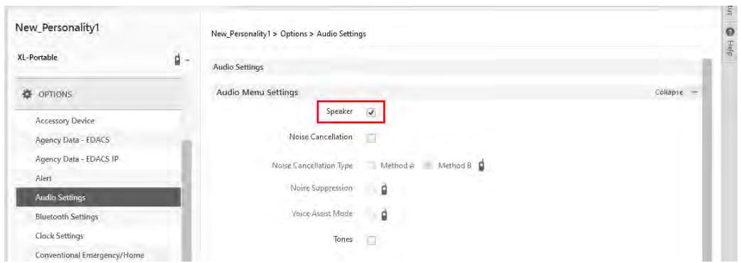
- Under OPTIONS Audio Settings PTT Options, check PTT and select Accessory Only.
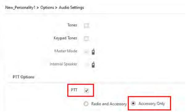
- (Optional) Configure Automatic Level Control (ALC). Enabling ALC uses proprietary L3Harris algorithms to adjust and level audio to compensate for users who speak loudly or speak softly to be heard at nearly the same level.

NOTE
Requires RPM2 R6A or later and XLP R6A or later. Consult with your L3Harris radio technician before adjusting any of these settings.
a. Select OPTIONS Audio Settings Bluetooth Microphone.
b. Check (enable) ALC.
c. Set ALC Max Gain to desired level (Default = 6 dB; Range = 0 dB to +12 dB in 1 dB increments). This setting allows the user to set the maximum gain applied by the ALC feature for transmitted voice. Higher gain settings increase the chance for acoustic feedback.
d. Set Mic Gain to desired level (Default = 16 dB; Range = -16 dB to +16 dB in 1 dB increments). This setting allows the user to set the Mic Gain for the Bluetooth External Microphone (baseline before ALC).
- Select OPTIONS Bluetooth Settings and check Bluetooth Enabled. Ensure MITM Protection Required is unchecked.
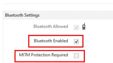
- Program a radio button or switch for Bluetooth Enable/Disable:
a. Select OPTIONS Portable Programmable Buttons or Programmable Switches.
b. Select Bluetooth Enable/Disable from the drop-down of the desired button/switch.
- Write the personality to the radio.
APPENDIX C CONFIGURING ENCRYPTION
Refer to the following documentation for advanced programming and setup instructions:
OTAR Overview Manual - MM-008069-001
Network Key Manager Installation and Configuration Manual - MM-008070-001
UAS Key Management Application Manual - MM-008068-001
Key Manager Key Admin Overview and Operation Manual - MM1000019423
Key Manager Key Loader Overview and Operation Manual - MM1000019424
Motorola® KVL User's Guide
C.1 CREATE KEYS USING L3HARRIS KEY ADMIN
L3Harris Key Admin is part of the L3Harris Key Manager and is used by the Crypto Officer (CO). The CO creates a Master Set of keys from which a Distribution Set is produced. Using the Key Admin software, the CO can save keys into Distribution key files for technicians to use in radios.
- Select Start Harris Key Manager Harris Key Admin.
- Select New Master Set, Open, or Import from Security Device. Refer to the Key Admin online help for more information on creating keys.
- When finished, create a Distribution Key File. A Distribution Key File is used with Key Loader to load key sets into the radio and cannot be edited. Refer to the Key Admin online help for more information on creating the Distribution Key File.
C.2 LOAD ENCRYPTION KEYS
C.2.1 Load UKEKS with Key Loader and RPM2 (for OTAR-Enabled Systems)
UKEKs are loaded into L3Harris OTAR-enabled radios using the Key Loader application. Key Loader is a part of Key Manager.
To load encryption keys:
- Obtain the UKEK file and Storage Location Number (SLN) Binding Report information from the Crypto Officer (CO).

AES and DES UKEKs can be contained within the same UKEK file.
- If not already on, power-up the PC on which RPM2 and Key Loader are installed.
- Connect the radio to the PC using the USB programming cable.
- Load the UKEK file from the Crypto Officer onto the PC.
- Run the RPM2 application and setup the radio's Personality according to the SLN Binding Report information.
-
Setup the talk groups and the SLN mappings (Talk Group ID to SLN). This includes mapping SLNs to the "System" keys (PSTN, All Call, etc.).
-
In RPM2, select P25 OPTIONS P25 OTAR/Keystores and set the following, referring to the RPM2 online help as necessary:
a. Click Create to add a Keystore or edit the Default Keystore.
b. Check Enable OTAR Options.
c. Enter the OTAR Message Number Period (MNP) as defined by the System Administrator.
d. Enter the radio's Individual RSI (from the SLN Bindings Report).
e. Enter the KMF's RSI (from the SLN Bindings Report).
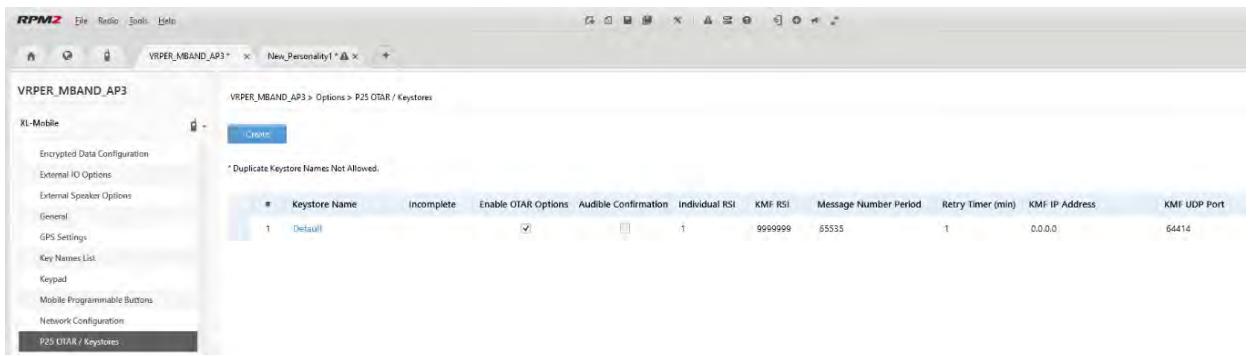
- Program the Personality to the radio.
- Run the Key Loader application.
- Open the UKEK file loaded in step 4.
- Select the Target Device type and click the Load button.
- The Key Loader reads the target device's identifying information, retrieves a UKEK of the proper algorithm type from the UKEK file, and downloads the UKEK to the target device at the proper SLN and keyset with the proper key ID.
- Click the button to exit the Key Loader application. New UKEKs are loaded and the radio is now ready to accept TEKs via OTAR with the trunked radio network.
C.2.2 Load Keys Using Key Loader
Key Loader is part of Key Manager and can be used by the Crypto Officer or Technician to load the keys into the radio.
Refer to the Key Loader online help if additional information is required when performing this procedure.
- Connect the radio to the PC using the programming cable.
- Power on the radio, if not already.
- Select Start Harris Key Manager Harris Key Loader.
- At the Key Loader Welcome screen, click Next.
- Select Load a Distribution Set into one or more devices.
- Click Next.
-
Browse to the Key File and enter the password.
-
Click Next to validate the password and continue. If the password is incorrect, the screen will display an error message.
- Ensure USB is selected in the drop-down and click Next.
- Select the radio from the drop-down and click Load.
- Click Finish.
C.3 PROTECTED KEYS
The Protected Keys feature transfers P25 Voice Keys, from Key Loader to the radio, that have been wrapped (AES) or encrypted (DES) with Key Protection Keys (KPKs). KPKs are unprotected Key Encryption Keys (KEKs). The KPKs need to be loaded into the radio before the Protected Keys are loaded. Once loaded into the radio, the KPKs are used to unwrap (AES) or decrypt (DES) the Protected Keys.
The radio must be placed into the key loading mode (see Section C.2.2) in order to accept the KPKs and P25 Voice Keys.
About L3Harris Technologies
L3Harris Technologies is an agile global aerospace and defense technology innovator, delivering end-to-end solutions that meet customers' mission-critical needs. The company provides advanced defense and commercial technologies across air, land, sea, space and cyber domains.