USER MANUAL XMAT R255SMS-DB+ EVOLUTION
Original Instruction
| Introduction | 3 |
| Warranty | 3 |
| Machine Specifications | 4 |
| Safety Labels & Symbols | 6 |
| Intended Use Of This Power Tool | 6 |
| Prohibited Use Of This Power Tool | 6 |
| Safety Precautions | 6 |
| Electrical Safety | 6 |
| Outdoor Use | 7 |
| General Power Tool Safety Instructions | 7 |
| Specific Safety Instructions | 8 |
| Blade Safety | 10 |
| Health Advice | 10 |
| Personal Protective Equipment (PPE) | 10 |
| Safe Operation | 10 |
| Perform Cuts Correctly & Safely | 11 |
| Additional Safety Advice | 11 |
| Getting Started | 12 |
| Unpacking | 12 |
| Serial No. / Batch Code | 13 |
| Additional Accessories | 13 |
| Items Supplied | 14 |
| Machine Overview | 15 |
| Assembly Diagrams | 17 |
| Saw Set Up Diagrams | 19 |
| Saw Usage Diagrams | 20 |
| Assembly & Preparation | 24 |
| Tools Needed | 24 |
| Installing The Blade | 26 |
| North American Models | 26 |
| Non-North American Models | 27 |
| Checking & Adjusting | 27 |
| Bevel Angles | 28 |
| 0° Bevel Stop Adjustment | 28 |
| 0° Bevel Pointer Adjustment | 28 |
| 45° Bevel Stop Adjustment | 28 |
| Machine Fence Alignment | 29 |
| The Depth Stop | 29 |
| Mitre Angle Pointer Adjustment | 29 |
| The Sliding Upper Fence Section | 29 |
| The Laser | 29 |
| Laser Safety | 30 |
| Laser Adjustment | 31 |
| Permanently Mounting The Mitre Saw | 31 |
| For Portable Use | 31 |
| The Hold Down Clamp | 32 |
| Front Clamp | 32 |
| Operation Instructions | 33 |
| Body & Hand Positioning | 33 |
| On/Off Trigger Switch | 33 |
| Preparing To Make A Cut | 33 |
| Chop Cutting | 33 |
| Slide Cutting | 34 |
| Mitre Cutting | 34 |
| Bevel Cutting | 35 |
| Compound Cutting | 35 |
| Crown Moulding Cutting | 35 |
| Cutting Bowed Material | 35 |
| Clearing Jammed Material | 35 |
| Optional Evolution Accessories | 36 |
| Maintenance | 36 |
| Tensioning The Drive Belt | 37 |
| Replacing The Drive Belt | 37 |
| Environmental Protection | 37 |
| Assembly Safety Checks | 38 |
| Final Safety Checks | 38 |
| EC Declaration of Conformity | 39 |
(1.3)IMPORTANT
Please read these operating and safety instructions carefully and completely.
For your own safety, if you are uncertain about any aspect of using this equipment please access the relevant technical helpline, the number of which can be found on the Evolution Power Tools website.
We operate several helplines throughout our worldwide organization, but technical help is also available from your supplier.
WEB: www.evolutionpowertools.com
UK/EU/AUS: customer.servicesevolutionpowertools.com
USA:evolutioninfo@evolutionpowertools.com
WARRANTY
(1.4) Congratulations on your purchase of an Evolution Power Tools Machine.
Please complete your product registration 'online' as explained on the leaflet included with this machine.
This will enable you to validate your machine's guarantee period via Evolution's website by entering your details and thus ensure prompt service if ever needed.
We sincerely thank you for selecting a product from Evolution Power Tools.
| MACHINE SPECIFICATION | UK/EU/AU |
| R225SMS-DB | R225SMS-DB+ |
| Model No: | 053-0001,053-0002,053-0003 | 053-0001A, 053-0002A,053-0003A, 053-0011 |
| Motor (220-240V ~ 50 Hz) | 2000W | 2000W |
| Motor (110V ~ 50 Hz) | 1600W | 1600W |
| Speed No Load | 2600 min-1 | 2600 min-1 |
| Weight (Net) | 16.5kg | 18.3kg |
| Dust Port Diameter | 35mm | 35mm |
| Cable Length | 3m | 4m |
| CUTTING CAPACITIES | R225SMS-DB | R225SMS-DB+ |
| Mild Steel Plate - Max Thickness | 6mm | 6mm |
| Mild Steel Box Section - Max Wall Thickness
(50mm mild steel box section.) | 3mm | 3mm |
| Wood - Max section | 300 x 80 mm | 300 x 90 mm |
| MITRE | BEVEL | R225SMS-DB | R225SMS-DB+ |
| 0° | 0° | 300mm x 80mm | 300mm x 90mm |
| 0° | 45° Left | 300mm x 46mm | 300mm x 52mm |
| 0° | 45° Right | 300mm x 27mm | 300mm x 34mm |
| 45° | 0° | 212mm x 80mm | 212mm x 90mm |
| 45° | 45° Left | 212mm x 46mm | 212mm x 52mm |
| 45° | 45° Right | 212mm x 27mm | 212mm x 34mm |
| 45° | 0° | 212mm x 80mm | 212mm x 90mm |
| BLADE SPECIFICATION | R225SMS-DB | R225SMS-DB+ |
| Diameter | 255mm | 255mm |
| Number Of Teeth | 24 | 28 |
| Bore | 25.4mm | 25.4mm |
| Kerf | 2mm | 2mm |
| LASER |
| Laser Class | Class 2 |
| Laser Source | Laser Diode |
| Laser Output Power (Max) | ≤1mW |
| Wave Length (Nm) | 650 |
| NOISE EMISSION DATA* |
| Sound Pressure Lpa (No-Load) | 110V: 96,4 dB(A) / 220-240V~ 96,9 dB(A) |
| Sound Power Level Lwa (No-Load) | 110V: 109,4 dB(A) / 220-240V~ 109,9 dB(A) |
| Uncertainty, KpA & KwA | K=3 dB(A) |
*Noise emission test according to EN 62841-1 & EN 62841-3-9.
WARNING: The noise emissions during actual use of the power tool can differ from the declared values depending on the ways in which the tool is used especially what kind of workpiece is processed.
WARNING: The need to identify safety measures to protect the operator that are based on an estimation of exposure in the actual conditions of use (taking account of all parts of the operating cycle such as the times when the tool is switched off and when it is running idle in addition to the trigger time).
| NORTH AMERICA |
| MACHINE SPECIFICATION | R225SMS-DB | R225SMS-DB+ |
| Model No: | 053-0004 | 053-0004A |
| Motor (120V ~ 60 Hz) | 15A | 15A |
| Speed No Load | 2600 rpm | 2600 rpm |
| Weight (Net) | 36.3lb | 40.3lb |
| Dust Port Diameter | 1 -3/8 In | 1 -3/8 In |
| Cable Length | 10ft | 13ft |
| CUTTING CAPACITIES | R225SMS-DB | R225SMS-DB+ |
| Mild Steel Plate - Max Thickness | 1/4 In | 1/4 In |
| Mild Steel Box Section - Max Wall Thickness
(2 in. mild steel box section.) | 1/8 In | 1/8 In |
| Wood - Max section | 11-3/4 In x 3-1/2 In | 11-3/4 In x 3-1/2 In |
| MITER | BEVEL | R225SMS-DB | R225SMS-DB+ |
| 0° | 0° | 12 In x 3-1/8 In | 12 In x 3-1/2 In |
| 0° | 45° Left | 12 In x 1-7/8 In | 12 In x 2-1/16 In |
| 0° | 45° Right | 12 In x 1 In | 12 In x 1-1/4 In |
| 45° | 0° | 8-3/8 In x 3-1/8 In | 8-3/8 In x 3-1/3 In |
| 45° | 45° Left | 8-3/8 In x 1-7/8 In | 8-3/8 In x 2-1/16 In |
| 45° | 45° Right | 8-3/8 In x 1 In | 8-3/8 In x 1-1/4 In |
| 45° | 0° | 8-3/8 In x 3-1/8 In | 8-3/8 In x 3-1/2 In |
| BLADE DIMENSIONS | R225SMS-DB | R225SMS-DB+ |
| Diameter | 10 In | 10 In |
| Number Of Teeth | 24 | 28 |
| Bore | 1 In | 1 In |
| Kerf | 5/64 In | 5/64 In |
| LASER | |
| Laser Class | Class 2 |
| Laser Source | Laser Diode |
| Laser Output Power (Max) | ≤1mW |
| Wave Length (Nm) | 650 |
| NOISE EMISSION DATA* | |
| Sound Pressure Lpa (No-Load) | 110V: 95,8 dB(A) / 220-240V~ 95,8 dB(A) |
| Sound Power Level Lwa (No-Load) | 110V: 108,8 dB(A) / 220-240V~ 108,8 dB(A) |
| Uncertainty, Kpa & Kwa | K=3 dB(A) |
*Noise emission test according to EN 62841-1 & EN 62841-3-9.
(1.8) SAFETY LABELS & SYMBOLS
WARNING: Do not operate this machine if warning and/or instruction labels are missing or damaged. Contact Evolution Power Tools for replacement labels.
Note: All or some of the following symbols may appear in the manual or on the product.
| Symbol | Description |
| V | Volts |
| A | Amperes |
| Hz | Hertz |
| min-1(RPM) | Speed |
| ~ | Alternating Current |
| no | No Load Speed |
| Wear Safety Goggles |
| Wear Ear Protection |
| Do Not Touch,
Keep hands away |
| Wear Dust Protection |
| Wear Hand Protection |
| CE | CE certification |
| ETL US
Intertek
5012207 | ETL Certification |
| 5490 | Regulatory Compliance Mark (RCM)
for electrical and electronic equipment.
Australian/New Zealand Standard |
| EAC | The Eurasian Conformity Mark (EAC)
Eurasian Customs Union |
| Waste Electrical and
Electronic Equipment |
| Read Manual |
| ! | WARNING |
| Laser Warning |
| Double Insulation Protection |
| — | Fuse |
| Triman - Waste Collection
& Recycling |
1. Replacement Parts
When servicing use only identical replacement parts.
2. Polarized Plugs
To reduce the risk of electric shock, this equipment has a polarized plug (one blade is wider than the other). This plug will fit in a polarized outlet only one way. If the plug does not fit fully in the outlet, reverse the plug. If it still does not fit, contact a qualified electrician to install the proper outlet. Do not change the plug in any way.
FOR NON-NORTH AMERICAN MODELS ONLY
WARNING: This product is a Multi-material sliding mitre saw and has been designed to be used with genuine Evolution blades rated for this machine. Only use blades designed for use in this machine and/or those recommended specifically by Evolution Power Tools Ltd.
WHEN FITTED WITH A CORRECT BLADE THIS MACHINE CAN BE USED TO CUT:
- Wood, Wood derived products (MDF, Chipboard, Plywood, Blockboard, Hardboard etc),
Wood with nails,
- 50mm mild steel box section with 3mm wall at HB 200-220,
- 6mm mild steel plate at HB 200-220.
Note: Wood containing non-galvanised nails or screws, with care, can be safely cut.
Note: Not recommended for cutting galvanised materials or wood with embedded galvanised nails.
Cutting galvanised steel may reduce blade life.
WARNING: This product is a Multi-material sliding mitre saw and must only be used as such. It must not be modified in any way, or used to power any other equipment or drive any other accessories other than those mentioned in this Instruction Manual.
(1.13) WARNING: This product is not intended for use by persons (including children) with reduced physical, sensory or mental capabilities, or lack of experience and knowledge, unless they have been given supervision or instruction concerning the safe use of the product by a person responsible for their safety and who is competent in its safe use.
SAFETY PRECAUTIONS
(1.14) ELECTRICAL SAFETY
This machine is fitted with the correct moulded plug and mains lead for the designated market. If the supply cord is damaged, it must be replaced by a special cord or assembly available from the manufacturers or its service agent.
For added protection use a residual current device (R.C.D.) that will interrupt the supply if the leakage current to earth exceeds 30mA for 30ms. Always check the operation of the residual current device (R.C.D.) before using the machine.
(1.15) OUTDOORUSE
WARNING: For your protection if this tool is to be used outdoors it should not be exposed to rain, or used in damp locations. Do not place the tool on damp surfaces. Use a clean, dry workbench if available. For added protection use a residual current device (R.C.D.) that will interrupt the supply if the leakage current to earth exceeds 30mA for 30ms. Always check the operation of the residual current device (R.C.D.) before using the machine. If an extension cable is required it must be a suitable type for use outdoors and so labelled. The manufacturers instructions should be followed when using an extension cable.
WARNING: When using electric tools basic safety precautions should always be followed to reduce the risk of fire, electric shock and personal injury including the following.
Note: This power tool should not be powered on continuously for a long time.
WARNING: Read all safety warnings and instructions before attempting to operate this product and save these instructions.
Failure to follow the warnings and instructions may result in electric shock, fire and/or serious injury.
SAVE ALL WARNING & INSTRUCTIONS FOR FUTURE REFERENCE
The term "power tool" in the warnings refers to your mains-operated (corded) power tool or battery-operated (cordless) power tool.
(2.2) 1. General Power Tool SafetyWarnings [Work area safety]
a) Keep work area clean and well lit.
Cluttered or dark areas invite accidents.
b) Do not operate power tools in explosive atmospheres, such as in the presence of flammable liquids, gasses or dust. Power tools create sparks which may ignite the dust or fumes.
c) Keep children and bystanders away while operating power tool. Distractions can cause you to lose control.
d) Do not use this machine in an enclosed room.
(2.3) 2. General Power Tool SafetyWarnings [Electrical Safety]
a) Power tool plugs must match the outlet. Never modify the plug in any way. Do not use any adapter plugs with earthed (grounded) power tools. Unmodified plugs and matching outlets will reduce the risk of electric shock.
b) Avoid body contact with earthed or grounded surfaces, such as pipes, radiators, ranges and refrigerators. There is an increased risk of electric shock if your body is earthed or grounded.
c) Do not expose power tools to rain or wet conditions. Water entering a power tool will increase the risk of electric shock.
d) Do not abuse the cord. Never use the cord for carrying, pulling or unplugging the power tool. Keep cord away from heat, oil, sharp edges or moving parts. Damaged or entangled cords increase the risk of electric shock.
e) When operating a power tool outdoors, use an extension cord suitable for outdoor use. Use of a cord suitable for outdoor use reduces the risk of electric shock.
f) If operating a power tool in a damp location is unavoidable, use a residual current device (RCD) protected supply. Use of an RCD reduces the risk of electric shock.
(2.4) 3) General Power Tool SafetyWarnings [Personal Safety].
a) Stay alert, watch what you are doing and use common sense when operating a power tool. Do not use a power tool while you are tired or under the influence of drugs, alcohol or medication. A moment of inattention while operating power tools may result in serious personal injury.
b) Use personal protective equipment. Always wear eye protection to prevent injury from sparks and chippings. Protective equipment such
as dust masks, non-skid safety shoes, hard hat or hearing protection used for appropriate conditions will reduce personal injuries.
c) Prevent unintentional starting. Ensure the switch is in the off-position before connecting to power source and or battery pack, picking up or carrying the tool. Carrying power tools with your finger on the switch or energising the power tools that have the switch on invites accidents.
d) Remove any adjusting key or wrench before turning the power tool on. A wrench or key left attached to a rotating part of a power tool may result in personal injury.
e) Do not overreach. Keep proper footing and balance at all times. This enables better control of the power tool in unexpected situations.
f) Dress properly. Do not wear loose clothing or jewellery. Keep your hair, clothing and gloves away from moving parts. Loose clothes, jewellery or long hair can be caught in moving parts.
g) If devices are provided for the connection of dust extraction and collection facilities, ensure that these are connected and properly used.
Use of dust collection can reduce dust-related hazards.
h) When cutting metal, gloves should be worn before handling to prevent from getting burnt from hot metal.
i) Keep handles and grasping surfaces dry, clean and free from oil and grease. Slippery handles and grasping surfaces do not allow for safe handling and control of the tool in unexpected situations.
(2.5) 4) General Power Tool SafetyWarnings [Power tool use and care].
a) Do not force the power tool. Use the correct power tool for your application. The correct power tool will do the job better and safer at a rate for which it was designed.
b) Do not use the power tool if the switch does not turn it on or off. Any power tool that cannot be controlled with the switch is dangerous and must be repaired.
c) Disconnect the power tool from the power source and/or battery pack from the power tool before making any adjustments, changing accessories, or storing power tools. Such preventative safety measures reduce the risk of starting the power tool accidentally.
d) Store idle power tools out of the reach of children and do not allow persons unfamiliar with the power tool or these Instructions to operate the power tool. Power tools are
dangerous in the hands of untrained users.
e) Maintain power tools. Check for misalignment or binding of moving parts, breakage of moving parts and any other condition that may affect the power tools operation. If damaged, have the power tool repaired before use. Many accidents are caused by poorly maintained power tools.
f) Keep cutting tools sharp and clean. Properly maintained cutting tools with sharp cutting edges are less likely to bind and are easier to control.
g) Use the power tool, accessories and tool bits etc. in accordance with these instructions, taking into account the working conditions and the work to be performed. Use of the power tool for operations different from those intended could result in a hazardous situation.
h) Keep handles and grasping surfaces dry, clean and free from oil and grease.
Slippery handles and grasping surfaces do not allow for safe handling and control of the tool in unexpected situations.
(2.6) 5) General Power Tool SafetyWarnings [Service] a) Have your power tool serviced by a qualified repair person using only identical replacement parts. This will ensure that the safety of the power tool is maintained.
If the supply cord of this power tool is damaged, it must be replaced by a specially prepared supply cord available through the service organization.
(3.5) MITRE SAW SPECIFIC SAFETY
- Not to use saw blades manufactured from high speed steel.
- Use only the saw with guards in good working order and properly maintained, and in position.
- Always to clamp work-pieces to the saw table.
a) Mitre saws are intended to cut wood or woodlike products, they cannot be used with abrasive cut-off wheels for cutting ferrous material such as bars, rods, studs, etc. Abrasive dust causes moving parts such as the lower guard to jam. Sparks from abrasive cutting will burn the lower guard, the kerf insert and other plastic parts.
b) Use clamps to support the workpiece whenever possible. If supporting the workpiece by hand, you must always keep your hand at least 150mm from either side of the saw blade. Do not use this saw to cut pieces that are too small to be securely clamped or held by hand. If your hand is placed too close to the saw blade, there is an increased risk of injury from blade contact.
c) The workpiece must be stationary and clamped or held against both the fence and the table. Do not feed the workpiece into the blade or cut "freehand" in any way. Unrestrained or moving workpieces could be thrown at high speeds, causing injury.
d) Push the saw through the workpiece.
Do not pull the saw through the workpiece. To make a cut, raise the saw head and pull it out over the workpiece without cutting, start the motor, press the saw head down and push the saw through the workpiece. Cutting on the pull stroke is likely to cause the saw blade to climb on top of the workpiece and violently throw the blade assembly towards the operator.
NOTE: The above warning is omitted for a simple pivoting arm metre saw.
e) Never cross your hand over the intended line of cutting either in front or behind the saw blade. Supporting the workpiece "cross handed" i.e. holding the workpiece to the right of the saw blade with your left hand or vice versa is very dangerous.
f) Do not reach behind the fence with either hand closer than 150mm from either side of the saw blade, to remove wood scraps, or for any other reason while the blade is spinning. The proximity of the spinning saw blade to your hand may not be obvious and you may be seriously injured.
g) Inspect your workpiece before cutting. If the workpiece is bowed or warped, clamp it with the outside bowed face toward the fence. Always make certain that there is no gap between the workpiece, fence and table along the line of the cut. Bent or warped workpieces can twist or shift and may cause binding on the spinning saw blade while cutting. There should be no nails or foreign objects in the workpiece.
h) Do not use the saw until the table is clear of all tools, wood scraps, etc., except for the workpiece. Small debris or loose pieces of wood or other objects that contact the revolving blade can be thrown with high speed.
i) Cut only one workpiece at a time. Stacked multiple workpieces cannot be adequately clamped or braced and may bind on the blade or shift during cutting.
j) Ensure the litre saw is mounted or placed on a level, firm work surface before use. A level and firm work surface reduces the risk of the litre saw becoming unstable.
k) Plan your work. Every time you change the bevel or mitre angle setting, make sure the adjustable fence is set correctly to support the
workpiece and will not interfere with the blade or the guarding system. Without turning the tool "ON" and with no workpiece on the table, move the saw blade through a complete simulated cut to assure there will be no interference or danger of cutting the fence.
NOTE: The phrase "bevel or" does not apply for saws without bevel adjustment.
I) Provide adequate support such as table extensions, saw horses, etc. for a workpiece that is wider or longer than the table top. Workpieces longer or wider than the metre saw table can tip if not securely supported. If the cut-off piece or workpiece tips, it can lift the lower guard or be thrown by the spinning blade.
m) Do not use another person as a substitute for a table extension or as additional support.
Unstable support for the workpiece can cause the blade to bind or the workpiece to shift during the cutting operation pulling you and the helper into the spinning blade.
n) The cut-off piece must not be jammed or pressed by any means against the spinning saw blade. If confined, i.e. using length stops, the cut-off piece could get wedged against the blade and thrown violently.
o) Always use a clamp or a fixture designed to properly support round material such as rods or tubing. Rods have a tendency to roll while being cut, causing the blade to "bite" and pull the work with your hand into the blade.
p) Let the blade reach full speed before contacting the workpiece. This will reduce the risk of the workpiece being thrown.
q) If the workpiece or blade becomes jammed, turn the litre saw off. Wait for all moving parts to stop and disconnect the plug from the power source and/or remove the battery pack. Then work to free the jammed material. Continued sawing with a jammed workpiece could cause loss of control or damage to the litre saw.
r) After finishing the cut, release the switch, hold the saw head down and wait for the blade to stop before removing the cut-off piece.
Reaching with your hand near the coasting blade is dangerous.
s) Hold the handle firmly when making an incomplete cut or when releasing the switch before the saw head is completely in the down position. The braking action of the saw may cause the saw head to be suddenly pulled downward, causing a risk of injury.
Note: The above warning applies only for mitre saws with a brake system.
BLADE SAFETY
WARNING: Rotating saw blades are extremely dangerous and can cause serious injury and amputation. Always keep fingers and hands at least 150mm (6") away from the blade at all times. Never attempt to retrieve sawn material until the cutting head is in the raised position, the guard is fully closed and the saw blade has stopped rotating. Only use saw blades that are recommended by the manufacturer and as detailed in this manual and that comply with the requirements of EN 847-1.
Only use genuine Evolution blades rated for this machine.
- Do not use saw blades that are damaged or deformed as they could shatter and cause serious injury to the operator or bystanders.
- If the table insert becomes damaged or worn it must be replaced with an identical one available from the manufacturer.
- Use only a saw blade diameter in accordance with the markings on the saw and information about the bore diameter and the maximum kerf of the saw blade.
- Use additional supports if needed to ensure the stability of the workpiece.
- Avoid overheating the saw blade tips and, if cutting plastics is permitted, avoid melting the plastic.
- Ensure that the metre saw is always stable and secure (e.g. fixed to a bench)
- Identify the correct saw blade to be used for the material to be cut.
(2.7) HEALTH ADVICE
WARNING: If you suspect that paint on surfaces in your home contains lead seek professional advice. Lead based paints should only be removed by a professional and you should not attempt to remove it yourself.
Once the dust has been deposited on surfaces, hand to mouth contact can result in the ingestion of lead. Exposure to even low levels of lead can cause irreversible brain and nervous system damage. The young and unborn children are particularly vulnerable.
(2.8) WARNING: Some wood and wood type products, especially MDF (Medium Density Fibreboard), can produce dust that may be hazardous to your health. We recommend the use of an approved face mask with replaceable filters when using this machine, in addition to using the dust extraction facility.
(3.6) PERSONAL PROTECTIVE EQUIPMENT (PPE)
Hearing protection should be worn in order to reduce the risk of induced hearing loss.
Eye protection should be worn in order to prevent the possibility of the loss of sight from ejected chippings.
Respiratory protection is also advised as some wood and wood type products especially MDF (Medium Density Fibreboard) can produce dust that can be hazardous to your health. We recommend the use of an approved face mask with replaceable filters when using this machine in addition to using the dust extraction facility.
Gloves should be worn when handling blades or rough material. Heat resistant gloves should be worn when handling metallic materials which may be hot. It is recommended that saw blades should be carried in a holder wherever practicable. It is not advisable to wear gloves when operating the mitre saw.
Always ensure that you have selected the correct saw blade for the material being cut. Do not use this metre saw to cut materials other than those specified in this Instruction Manual.
When transporting a litre saw ensure that the cutting head is locked in the 90^ down position (if a sliding litre saw ensure that the slide bars are locked). Lift the machine by gripping the outer edges of the base with both hands (if a sliding litre saw, transport using the handles provided). Under no circumstances shall the machine be lifted or transported using the retractable guard or any part of its operating mechanism.
Bystanders and other colleagues must be kept at a safe distance from this saw. Cut debris can, in some circumstances, be ejected forcibly from the machine, posing a safety hazard to people standing nearby.
Before each use check the operation of the retractable guard and its operating mechanism ensuring that there is no damage, and that all moving parts operate smoothly and correctly. Keep the work bench and floor area clear of all debris including sawdust, chips and off-cuts.
Always check and ensure that the speed marked on the saw blade is at least equal to the no load speed marked on the mitre saw. Under no circumstances shall a saw blade be used that is marked with a speed that is less than the no-load speed marked on the mitre saw.
Where it is necessary to use spacer or reducing rings these must be suitable for the intended purpose and only as recommended by the manufacturer.
If the mitre saw is fitted with a laser it shall not be replaced with a different type. If the laser fails to operate it shall be repaired or replaced by the manufacturer or authorised agent.
The saw blade shall only be replaced as detailed in this instruction manual.
Never attempt to retrieve off-cuts or any other part of the work-piece until the cutting head is in the raised position, the guard is fully closed and the saw blade has stopped rotating.
WARNING: Only check the operation of the blade guarding system with the machine disconnected from the power supply. To check blade guard operation: Raise and lower the Cutting Head several times and visually check the operation of the retractable blade guard.
Note: The retractable blade guard should exhibit no signs of judder but smoothly draw into the upper blade guard as the Cutting Head is lowered. As the Cutting Head is returned to the upper position, the blade guard should emerge from the upper blade guard to fully enclose the machines blade.
- Ensure that in the full upper position the Cutting Head is locked in place by the Blade Guard.
Wherever practicable always secure the work-piece to the saw table using the work clamp where provided.
Always ensure that before each cut the litre saw is mounted in a stable position.
If needed the litre saw can be mounted on a wooden base or work bench or attached to a litre saw stand as detailed in this instruction manual. Long work-pieces should be supported on the work supports provided or on appropriate additional work supports.
(2.8) WARNING: The operation of any litre saw can result in foreign objects being thrown towards your eyes, which could result in severe eye damage. Before beginning power tool operation, always wear safety goggles or safety glasses with side shield or a full face shield when needed.
WARNING: If any parts are missing, do not operate your mitre saw until the missing parts are replaced. Failure to follow this rule could result in serious personal injury.
(3.9)ADDITIONAL SAFETY ADVICE CARRYING YOUR MITRE SAW
WARNING: When using electric tools basic safety precautions should always be followed to reduce the risk of fire, electric shock and personal injury including the following.
READ all these instructions before attempting to operate this product and save these instructions.
Safety Advice:
- Although compact, this litre saw is heavy. To reduce the risk of back injury, get competent help whenever you have to lift the saw.
- Hold the tool close to your body when lifting. Bending your knees so you can lift with your legs, not your back. Lift by using the cutting handle on the head of the metre saw and the large, orange handle on the rear of the carriage slide.
- Never carry the metre saw by the power cord. Carrying the metre saw by the power cord could cause damage to the insulation or the wire connections resulting in electric shock or fire.
Before moving the litre saw tighten the litre and bevel locking screws and the sliding carriage locking screw to guard against sudden unexpected movement.
- Lock the cutting head in its lowest position.
Ensure that the cutting head locking pin is completely engaged in its socket.
WARNING: Do not use the blade guard as a 'lifting point'. The power cord must be removed from the power supply before attempting to move the machine.
- Lock the cutting head in the down position using the cutting head locking pin.
- Loosen the Mitre Angle locking screw. Turn the table to either of its maximum settings.
- Lock the table in position using the locking screw.
- Wrap the cable around the cable guide.
ADDITIONAL WARNINGS
(These warnings are specified in UL Std. 987 and CAN/CSA Std.C22.2 No. 71.2)
- Keep guards in place and in working order.
- Remove adjusting keys and wrenches. Form habit of checking to see that keys and adjusting wrenches are removed from tool before turning it on.
- Keep work area clean. Cluttered areas and benches invite accidents.
- Don't use in dangerous environment. Don't use power tools in damp or wet locations, or expose them to rain. Keep work area well lit.
- Keep children away. All visitors should be kept safe distance from work area.
- Make workshop child proof with padlocks, master switches, or by removing starter keys.
- Don't force the tool. It will do the job better and safer at the rate for which it was designed.
- Use the right tool. Don't force the tool or attachment to do a job for which it was not designed.
- Use proper extension cord. Make sure your extension cord is in good condition. When using an extension cord, be sure to use one heavy enough to carry the current your product will draw. An undersized cord will cause a drop in line voltage resulting in loss of power and overheating. The table on the next page shows the correct size to use depending on cord length and nameplate ampere rating. If in doubt, use the next heavier gauge. The smaller the gauge number, the heavier the cord.
- Wear proper apparel do not wear loose clothing, gloves, neckties, rings, bracelets, or other jewellery which may get caught in moving parts. Nonslip footwear is recommended. Wear protective hair covering to contain long hair.
- Always use safety glasses. Also use face or dust mask if cutting operation is dusty. Everyday eyeglasses only have impact resistant lenses, they are not safety glasses.
- Secure work. Use clamps or a vise to hold work when practical. It's safer than using your hand and it frees both hands to operate tool.
- Don't overreach. Keep proper footing and balance at all times.
- Maintain tools with care. Keep tools sharp and clean for best and safest performance. Follow instructions for lubricating and changing accessories.
-
Disconnect tools before servicing; when changing accessories, such as blades, bits, cutters, and the like.
-
Reduce the risk of unintentional stating. Make sure switch is in off position before plugging in.
- Use recommended accessories. Consult the owner's manual for recommended accessories. The use of improper accessories may cause risk of injury to persons.
- Never stand on the tool serious injury could occur if the tool is tipped or if the cutting tool is unintentionally contacted.
- Check damaged parts. Before further use of the tool, a guard or other part that is damaged should be carefully checked to determine that it will operate properly and perform its intended function - check for alignment of moving parts, binding of moving parts, breakage of parts, mounting, and any other conditions that may affect its operation. A guard or other part that is damaged should be properly repaired or replaced.
- Direction of feed. Feed work into a blade or cutter against the direction of rotation of the blade or cutter only.
- Never leave tool running unattended. Turn power off. Don't leave the tool until it comes to a complete stop.
(4.1)GETTING STARTED - UNPACKING
Caution: This packaging contains sharp objects. Take care when unpacking. This machine could require two persons to lift, assemble and move this machine. Remove the machine, together with the accessories supplied from the packaging. Check carefully to ensure that the machine is in good condition and account for all the accessories listed in this manual. Also make sure that all the accessories are complete. If any parts are found to be missing, the machine and its accessories should be returned together in their original packaging to the retailer. Do not throw the packaging away; keep it safe throughout the warranty period. Dispose of the packaging in an environmentally responsible manner. Recycle if possible. Do not let children play with empty plastic bags due to the risk of suffocation.
SERIAL NO./BATCH CODE
The serial number can be found on the motor housing of the machine. For instructions on how to identify the batch code, please contact the Evolution Power Tools helpline or go to: www.evolutionpowertools.com.
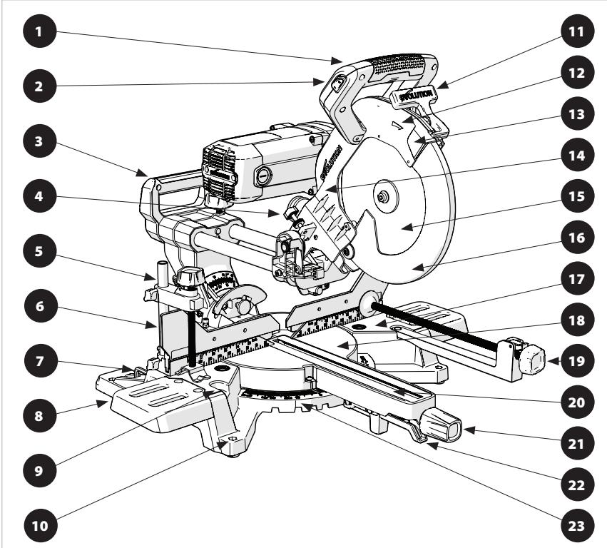
(4.3) ADDITIONAL ACCESSORIES
In addition to the standard items supplied with this machine the following accessories are also available from the Evolution online shop at www.evolutionpowertools.com or from your local retailer.
(4.4)
| Description | Part No |
| RAGE Multi-Material TCT Blade | RAGEBLADE255MULTI |
| Dust Bag | 030-0309 |
| Front Clamp | 052-0052 |
4.2) ITEMS SUPPLIED
These items can be found in the box.
| 053-0001
053-0002
053-0003
053-0004 | 053-0001A
053-0002A
053-0003A
053-0011 | 053-0004A |
| Machine Table Extensions x2 | ✓ | ✓ | ✓ |
| 6mm & 4mm Dual Ended Hex Key | ✓ | ✓ | ✓ |
| Rotary Table And Neck | ✓ | ✓ | ✓ |
| Cutting Head | ✓ | ✓ | ✓ |
| Carriage Slides | ✓ | ✓ | ✓ |
| Mitre Locking Knob | ✓ | ✓ | ✓ |
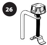
| Mains Cable Guide/Clamp | ✓ | ✓ | ✓ |
| Self Tapping Cap Screw x1 | ✓ | ✓ | ✓ |
| M6 x 16mm Socket Headed Screws x4 | ✓ | ✓ | ✓ |
| M5 x 12mm Socket Headed Screws x2 | ✓ | ✓ | ✓ |
| Laser Lens Cap | ✓ | ✓ | ✓ |
| Cable Clip | ✓ | ✓ | ✓ |
| Slide Locking Knob | ✓ | ✓ | ✓ |
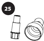
| Dust Port Adaptor | | ✓ | ✓ |
| Dust Collection Bag | | ✓ | ✓ |
| Hold Down Clamp | ✓ | | |
| Quick Release Hold Down Clamp | | ✓ | ✓ |
| Front Clamp | | ✓ | |
| 255mm (10 In) 24 Tooth Blade | ✓ | | |
| 255mm (10 In) 28 Tooth Blade | | ✓ | ✓ |
| Instruction Manual | ✓ | ✓ | ✓ |
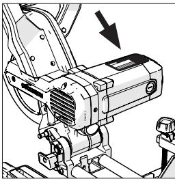
MACHINE OVERVIEW


- CUTTING HANDLE
- LASER GUIDE ON/OFF SWITCH
- REAR CARRY HANDLE*
- TRENCH STOP
- QUICK RELEASE HOLD DOWN CLAMP*
- SLIDING FENCE
- HEX KEY STORAGE
- MACHINE TABLE EXTENSIONS
- FRONT CLAMP HOLES
- MOUNTING HOLE (X4)
- BLADE GUARD LOCKING TRIGGER†
- BLADE ROTATION INDICATION ARROW
- UPPER BLADE GUARD
- CUTTING HEAD
15.BLADE
*Supplied as original equipment on the R255SMS-DB+. 'North American models only.
†Non-North American models only. ‡230v models only.
Pictured: R255SMS-DB+
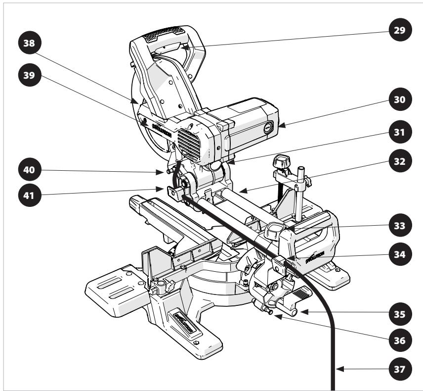
- ON/OFF TRIGGER SWITCH
- CARBON BRUSH HOLDER
- DUST EXTRACTION PORT
- REAR SLIDING CARRIAGE
- SLIDE LOCKING SCREW
- REAR CABLE GUIDE CLAMP
- BEVE L LOCK HANDLE
- LEFT 33.9^ BEVEL PIN
- MAINS POWER CABLE
-
ARBOR LOCK BUTTON
-
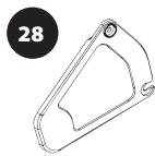
DRIVE BELT COVER
- CUTTING HEAD LOCKING PIN
- FRONT CABLE GUIDE CLAMP
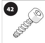
- M5 X 20mm SELF TAPPING CAP SCREW X1
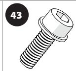
- M6 X 16mm SOCKET HEAD SCREW X4
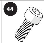
- M6 X 12mm HEAD SECURING SOCKET HEAD SCREWX X2
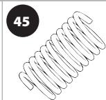
- ANTI-VIBRATION SPRING (FITTED TO ITEM '33'-THE SLIDE LOCKING SCREW)
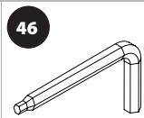
- 6mm & 4mm DUAL ENDED HEX KEY
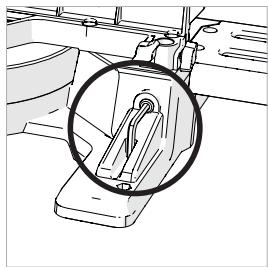
Fig. 1
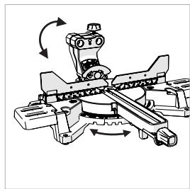
Fig. 2
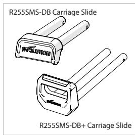
Fig. 3
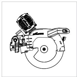
Fig. 4
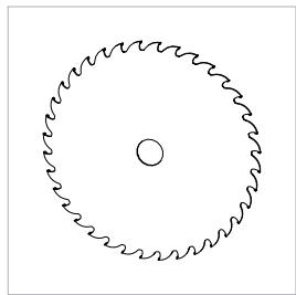
Fig. 5
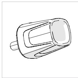
Fig. 6
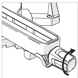
Fig. 7
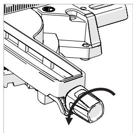
Fig. 8
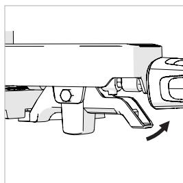
Fig. 9
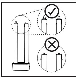
Fig. 10
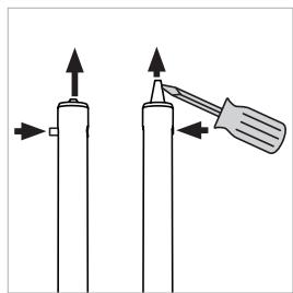
Fig. 11
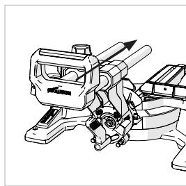
Fig. 12
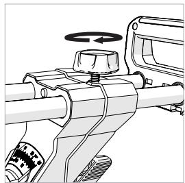
Fig. 13
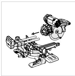
Fig. 14a
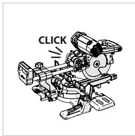
Fig. 14b
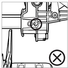
Fig. 15a
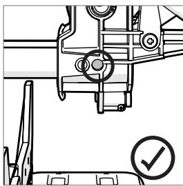
Fig. 15b
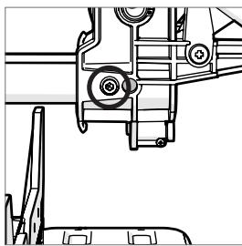
Fig. 15c
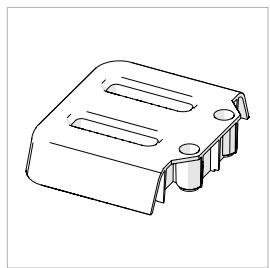
Fig. 16
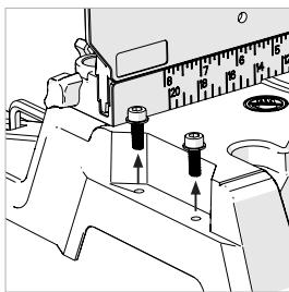
Fig.17
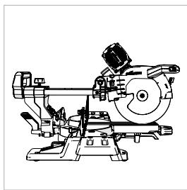
Fig. 18
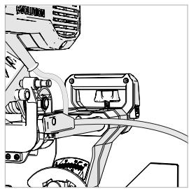
Fig. 19
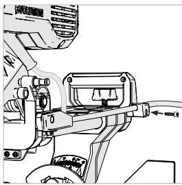
Fig. 20
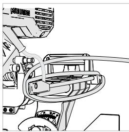
Fig. 21
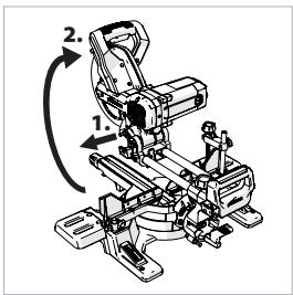
Fig. 22
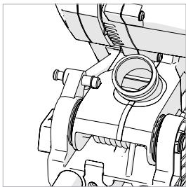
Fig. 23
Fig. 24
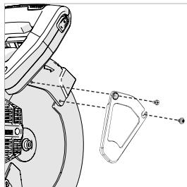
Fig. 25
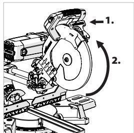
Fig. 26
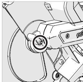
Fig. 27
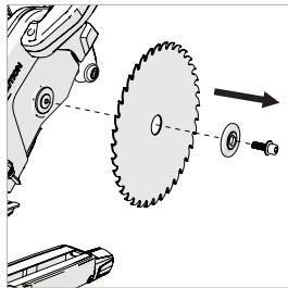
Fig. 28
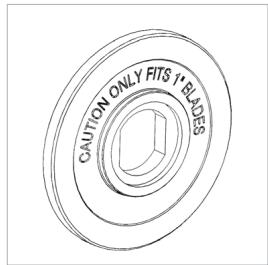
Fig. 29a
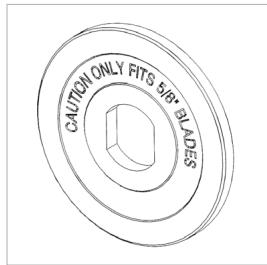
Fig. 29b
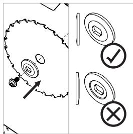
Fig. 30
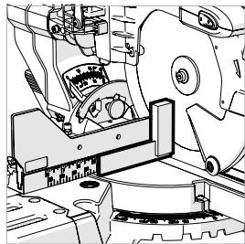
Fig. 31
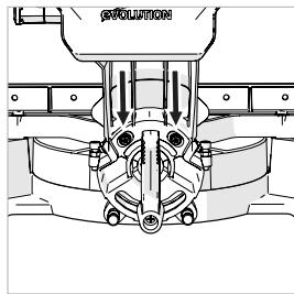
Fig. 32
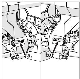
Fig. 33
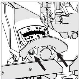
Fig. 34
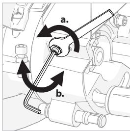
Fig. 35
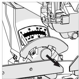
Fig. 36
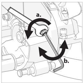
Fig. 37
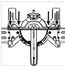
Fig. 38

Fig. 39
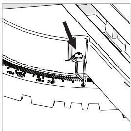
Fig. 40
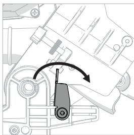
Fig. 41a
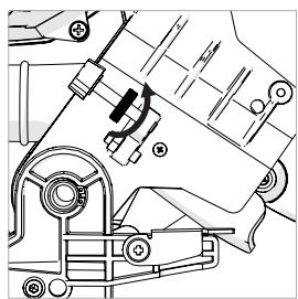
Fig. 41b

Fig. 41c
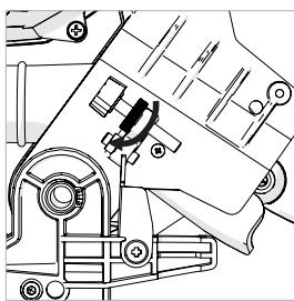
Fig. 41d
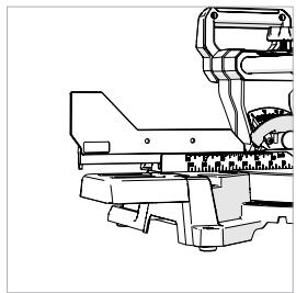
Fig. 42
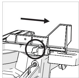
Fig. 43
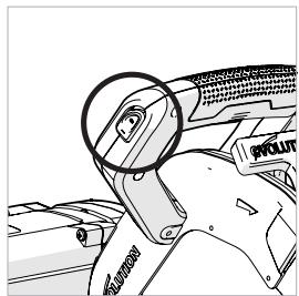
Fig. 44
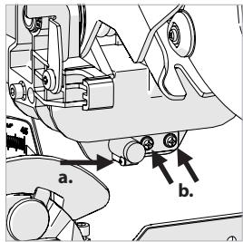
Fig. 45
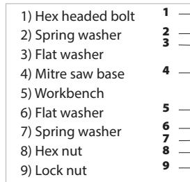
Fig.46
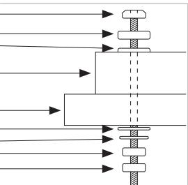
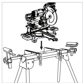
Fig. 47
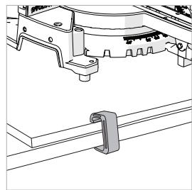
Fig. 48
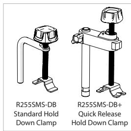
Fig. 49
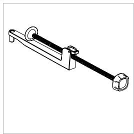
Fig. 50
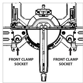
Fig. 51
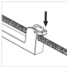
Fig. 52
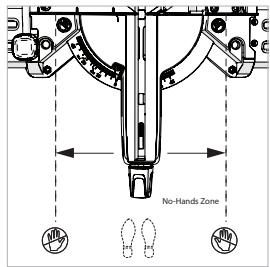
Fig. 53
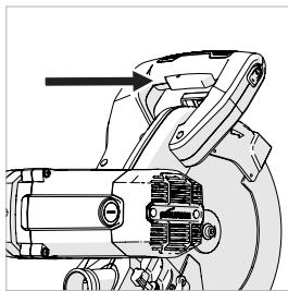
Fig. 54
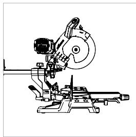
Fig. 55
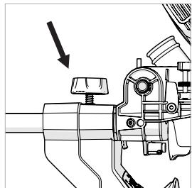
Fig. 56

Fig. 57
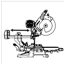
Fig. 58
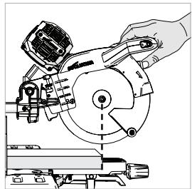
Fig. 59
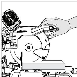
Fig. 60
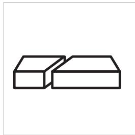
Fig. 61
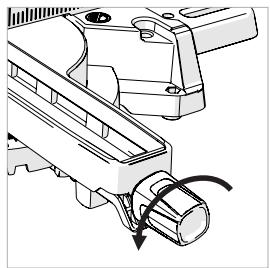
Fig. 62
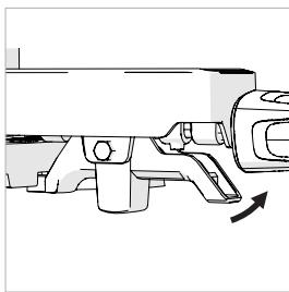
Fig. 63
Fig. 64
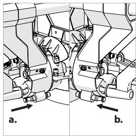
Fig. 65
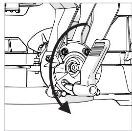
Fig. 66
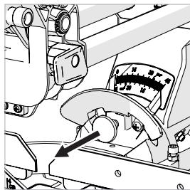
Fig. 67
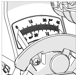
Fig. 68
Fig. 69
Fig. 70
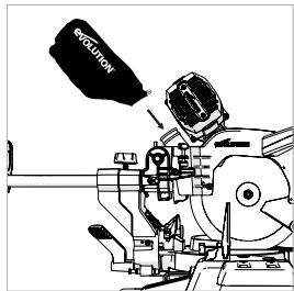
Fig. 71
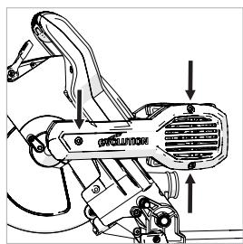
Fig. 72
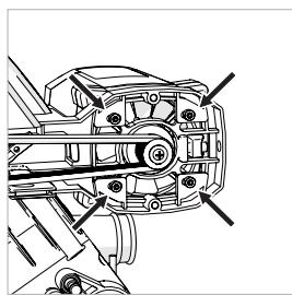
Fig. 73
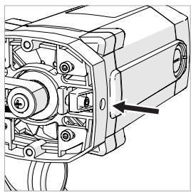
Fig. 74
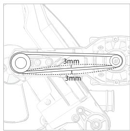
Fig. 75
(7.1) ASSEMBLY AND PREPARATION WARNING: Always disconnect the saw from the power source before making any adjustments.

Some minor assembly is required to commission this machine.
By assembling this machine the owner/ operator will gain valuable insight into its many advanced features. This should enable the operator to exploit the machines full potential once it is commissioned.
Note: Study the diagrams showing the assembled machine. You will gain valuable insight which will help you with the assembly process.
- 4mm & 6mm Hex Key - Supplied and located in a dedicated storage position on the machine. (Fig. 1)
3mm Hex Key
- 5mm Hex Key
- Flat Bladed Screwdriver - Not supplied.
-
2 Phillips Screwdriver - Not supplied.
Crosshead Screwdriver - Not supplied.
- 10mm Spanner - Not supplied.
Note: The assembly process is a 'one time assembly'.
Once assembly is successfully completed no attempt to disassemble the machine should be made.
The blade and some other smaller parts also need to be fitted by the owner/operator.
Note: A safety check must be carried out once assembly is completed and before the machine is used - see page 36.
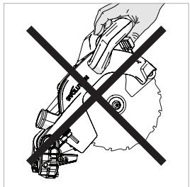
WARNING: Do not under any circumstances plug the cutting head into the power supply and try to use it as a hand held circular saw.
KNOW THE PARTS
There are four (4) main parts to be assembled (including the blade), and two (2) other smaller parts to be connected. Additionally the blade (supplied) will need to be fitted.
The rotary base and bevel neck (Fig. 2)
The carriage slides (Fig. 3)
- The cutting head (in the 'locked down position as removed from the packaging) (Fig. 4)
The Blade (Fig. 5)
Note: The Blade should be the last part to be fitted. It must only be fitted after the assemble process is completed and the machine has been subjected to the Assembly Safety Checks - see page 36.
THE MITRE LOCKING KNOB (Fig. 6)
The threaded spigot of the Mitre Locking Knob slides through a hole in the front of the Mitre Locking Handle (Fig. 7) and then screws into an internally threaded boss located in the base of the machine.
Before the machine can be assembled, the rotary base needs to be rotated to 0^ .
- Loosen the mitre handle locking knob (Fig. 8) by turning the locking knob anti-clockwise.
- Pull up the positive stop locking lever. (Fig. 9)
- Turn the rotary table to the 0^ .
- Lock the Mitre Locking Knob.
THE BEVEL NECK
Note: The bevel neck is supplied fitted to the Rotary table. The bevel neck should be adjusted to the 0^ position.
- Slacken the Bevel Locking screw using the Bevel Locking Handle. (Fig. 66)
- Rotate the bevel neck to the vertical position so that it rests against the 0^ stop.
- Tighten the Bevel Locking Handle.
INSERTING THE CARRIAGE SLIDE
IMPORTANT: If for any reason (transit damage, unpacking error, operator mistake, etc.) the locating pins at the tip of the carriage slide arms have been 'stripped', the sliding carriage cannot be fitted into the bevel neck or onto the cutting head.
The locating pins must be reset, if either or both have been 'tripped' prematurely. (Fig.10)
Resetting the locating pins:
- Gently push the protruding lug into the Carriage arm.
- Gently ease the locating lug deployment plunger forward by using a flat bladed screwdriver (not supplied) as a lever. (Fig. 11)
The carriage slides two (2) arms should be inserted through the two linear bearings contained within the bevel neck.
The carriage slide should be inserted from the back ensuring that the 'Evolution' logo is the correct way up. (Fig. 12)
- Slide the sliding carriage arms through the bevel neck for approximately half of their length.
- Screw the carriage slide locking screw into the threaded hole above the right hand arm of the carriage slide. (Fig. 13)
Note: Ensure that the anti-vibration spring is fitted underneath the hand knob before fitting the locking screw into its service position.
- Tighten the locking screw to lock the sliding carriage into the desired position.
ATTACHING THE CUTTING HEAD
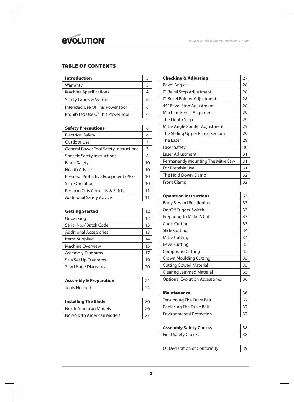
- Align the cutting head with the two (2) sliding carriage arms. (Fig. 14a)
- Push the cutting head onto the Carriage arms firmly until the 'click' of the Locating Pins deploying is heard. (Fig. 14b)
Note: The deployed locating pins must be fully visible when viewed from the side of the cutting head. (Figs. 15a, 15b) The Locating Pins are coloured green to make identification easy.
Two M6 x 12mm screws are supplied which should be screwed into the head of the saw where it meets the rear sliding carriage rails. This secures the rails in place reducing any wobble that may occur. (Fig. 15c) The two screws are supplied with the rear cable guide clamp in the packaging. These 2 screws can be fitted with the supplied 4mm hex key.
THE MACHINE TABLE EXTENSIONS (Fig. 16)
Two (2) machine table extension pieces are provided with this machine.
To fit the table extensions:
- Remove the socket headed screws from the table using the supplied 4mm hex key. (Fig. 17)
- Position the Extension piece onto the table and secure it into its service position using the socket headed screws.
- Repeat for the second Extension piece.
WARNING: This machine is equipped with a mains cable and a moulded plug which satisfies the regulations of the receiving country. This cable and plug, if damaged, should only be replaced with genuine Evolution replacement parts and be fitted by a competent technician.
- Ensure that the cutting head is in the down position.
- Ensure that the carriage slide is in its most forward position and locked. (Fig. 18)
From the motor the mains cable is pre-routed through the front cable guide. The cable should then be routed rearwards. (Fig. 19)
The cable should be inserted into the rear cable guide/clamp. For 230v models, ensure the Cable Grip Component is inside the cable guide when the cable passes through.
This guide/clamp should then be fastened to the rear sliding carriage cross piece (right hand side) using the self tapping cap screw (included). (Fig. 20)
Note: The cable should not be stretched or taught anywhere along its length. (Fig. 21)
Raise and lower the cutting head several times (see the section below - 'Unlatching and Raising the Cutting Head') and also operate the sliding carriage. Check that the cable does not become entangled with any other parts of the machine. Check also that the cable is not stretched during any of the operating procedures. To secure the cable, secure the cable using the cable clip.
Note: The cable guides can be used to provide a very convenient way of storing the mains cable on the machine when the machine itself is not being used and is perhaps in storage.
UNLATCHING AND RAISING THE CUTTING HEAD (Fig. 22)
WARNING: To avoid serious injury, NEVER perform the locking or unlocking procedure unless the saw is OFF and the blade stationary.
To release the cutting head from the locked down position:
Gently press down on the Cutting Head Handle.
- Supporting the head, pull out the head latching pin (Step 1) and allow the cutting head to rise to its upper position.(Step 2)
Note: The cutting head will automatically rise to the upper position once it is released from the locked down position. It will automatically lock in the upper position.
If release is difficult:
Gently rock the cutting head up and down.
- At the same time twist the Head Latching Pin clockwise and pull outwards.
Note: We recommend that when the machine is not in use the cutting head is locked in its down position with the latching pin fully engaged in the open half socket which is machined into the cutting head upper surface near to the pivot point. (Fig. 23).
INSTALLING OR REMOVING A BLADE
NORTH AMERICAN MODELS ONLY
WARNING: Only carry out this operation with the machine disconnected from the mains supply.
Note: It is recommended that the operator considers wearing protective gloves when handling the blade during installation or when changing the blade.
Ensure the cutting head is in its upper position. (Fig. 24)
- Remove the blade arbor cover by unscrewing the 2 screws with a crosshead screwdriver. (Fig. 25)
- Rotate the lower blade guard up and into the upper blade guard (Fig. 26 - step 2).
Note: Lowering the cutting head slightly will allow the lower blade guard to rotate fully into the upper blade guard giving maximum access for the operator.
- Press the black arbor lock button to lock the arbor. (Fig. 27) You may need to rotate the arbor slightly for the arbor lock to engage.
- Using the supplied Hex Key, release the flange bolt and outer blade flange and the blade (if fitted) from the arbor. (Fig. 28)
Note: The arbor screw has a LH (left hand) thread.
Turn clockwise to loosen.
Turn counterclockwise to tighten.
Ensure that the blade and blade flanges are clean and free from any contamination.
1" (25.4mm) ARBOR BLADES
You must ensure the dual-sided inner flange 1'' side is visible to you. (Fig. 29a)
Do not fit a 5 / 8'' (16mm) arbor blade when the inner-flange is in this configuration.
- The 'CAUTION ONLY FITS 1" BLADES' text is required to point 'outwards' from the motor when fitting a 1" (25.4mm) arbor blade, as this provides a 1" (25.4mm) arbor.
5/8" (16mm) ARBOR BLADES
You must ensure the dual-sided inner flange 5 / 8'' side is visible to you. (Fig. 29b)
Do not fit a 1'' (25.4mm) arbor blade when the inner-flange is in this configuration.
The 'CAUTION ONLY FITS 5/8" BLADES' text is required to point 'outwards' from the motor when fitting a 5 / 8'' (20mm) arbor blade, as this provides a 5 / 8'' (20mm) arbor.
Install the new blade. Make sure the rotation arrow on the blade matches the clockwise rotation arrow on the upper guard.
Note: The blade teeth should always point downward at the front of the saw.
- Install the outer blade flange making sure it is fitted the correct way around, then refit flange bolt. (Fig. 30)
- Lock the arbor and tighten the arbor screw using moderate force, but do not overtighten.
- Refit the blade arbor cover.
- Ensure the Hex Key is removed and the arbor lock has released before proceeding.
- Ensure the blade guard is fully functional before using the machine.
NON-NORTH AMERICAN MODELS
WARNING: Only carry out this operation with the machine disconnected from the mains supply.
WARNING: Only use genuine Evolution blades or those blades specifically recommended by Evolution Power Tools and which are designed for this machine. Ensure that the maximum speed of the blade is higher than the speed of the motor.
Note: It is recommended that the operator considers wearing protective gloves when handling the blade during installation or when changing the blade.
Ensure the cutting head is in its upper position. (Fig. 25)
- Press the lower blade guard locking trigger (Fig. 26-step 1).
- Rotate the lower blade guard up and into the upper blade guard (Fig. 26 - step 2).
Note: Lowering the cutting head slightly will allow the lower blade guard to rotate fully into the upper blade guard giving maximum access for the operator.
- Press the black arbor lock button to lock the arbor. (Fig. 27) You may need to rotate the arbor slightly for the arbor lock to engage.
- Using the supplied Hex Key, release the flange bolt and outer blade flange and the blade (if fitted) from the arbor. (Fig. 28)
Note: The arbor screw has a LH thread.
Turn clockwise to loosen. Turn counterclockwise to tighten.
Ensure that the blade and blade flanges are clean and free from any contamination.
- The inner blade flange should be left in place, but if it is removed for cleaning it must be replaced the same way round as it was removed from the machine.
Install the new blade. Make sure the rotation arrow on the blade matches the clockwise rotation arrow on the upper guard.
Note: The blade teeth should always point downward at the front of the saw.
Install the outer blade flange making sure it is fitted the correct way around, then refit flange bolt. (Fig. 30)
- Lock the arbor and tighten the arbor screw using moderate force, but do not overtighten.
- Ensure the Hex Key is removed and the arbor lock has released before proceeding.
- Ensure the blade guard is fully functional before using the machine.
CHECKING AND ADJUSTING OF THE PRECISION ANGLES
Note: This machine has been accurately set up and adjusted at the factory. If it is suspected that some of the precision angles have been lost they can be reset by following the procedure outlined below.
Note: Several checks/adjustments are possible on this machine. Please read the entire angle adjustment section before attempting to adjust the angles on the machine. It is recommended that the adjustments only be made by someone who is confident it their ability to do so. The operator will require a set square (triangle) (not supplied) or similar to carry out these checks and adjustments. If bevel adjustment proves difficult, please contact Evolution Customer Services on the appropriate helpline on rear cover of this manual.
WARNING: Checks/adjustments must only be conducted with the machine disconnected from the power supply.
0^ Bevel Stop Adjustment
- Ensure that the Cutting Head is in the locked down position with the latching pin fully engaged in its socket.
- Ensure that the Bevel Neck is upright (rotated clockwise), against its stop.
- Lock Bevel Lock Handle.
- Place a set square (triangle) or similar on the table with one edge against the table and the other edge against the blade (avoiding the TCT tips). (Fig. 31)
If the blade is not at 90^ (square) with the rotary table, then adjustment is required.
- Using the supplied 4mm hex key, loosen the two (2) socket headed cap screws on the rear of the Bevel arm. (Fig. 32)
- Unlock the Bevel Lock Handle.
- Use two 3mm hex keys, one inserted into the LH (Left Hand) (a) grab screw, with the other inserted into the RH (Right Hand) (b) grab screw. (Fig. 33)
- Turn one of the grub screws very slightly as if loosening it, whilst at the same time tightening the other grub screw by the same amount
- Turning the left grab screw moved the head vertical position to the right and turning the right grab screw will move the head vertical position to the left.
- The Bevel arm will move slightly, to the right or left, depending upon which direction the grub screws are being turned.
- The operator should check frequently the alignment of the blade with the square, making sure to move the head against its upright stop and lock the Bevel Lock Handle each time a check is made. If further adjustment is needed, repeat the above procedure.
- When accurate alignment has been achieved, tighten the two (2) cap screws at the rear of the Bevel arm. (Fig. 32)
0^ Bevel Pointer Adjustment
Note: The operator must be satisfied that the blade is set exactly perpendicular to the table when in the upright position and against its stop. There are two Bevel Pointers; one for left bevel and one for right bevel.
- If either pointer is not in exact alignment with the 0^ mark on the protractor scale adjustment is necessary.
- Loosen the necessary Bevel Pointer screw
(Fig. 34) using a #2 Phillips screwdriver.
- Adjust the Bevel Pointer so that it is in alignment exactly with the 0^ mark.
- Hold the pointer in place whilst tightening the screw.
45^ Left Hand Bevel Stop Adjustment
- Slide the left upper section of fence away from the blade by loosening the thumbscrew. (Fig. 43)
- Loosen the Bevel Lock Handle and tilt the Cutting Head completely to the left until it rests against the 45^ stop.
- Use a set square (triangle) or similar to see if the blade is at 45^ to the table (avoiding the TCT tips).
If the saw blade is not in exact alignment adjustment is necessary.
- Return the Cutting Head to its upright position.
- Loosen the locknut on the right 45^ Bevel Adjustment Screw with a 10mm spanner. (Fig. 35-a)
- Use a 3mm Hex Key to adjust the Adjustment Screw in or out as required. (Fig. 35-b)
- Tilt the Cutting Head to the 45^ setting and recheck for alignment with the set square.
- Repeat the above steps until the correct angular alignment is achieved.
- Hold the Adjustment Screw in place with the hex key and tighten the Adjustment Screw locknut securely once alignment is achieved.
- Lock the Bevel Lock Handle.
45° Right Hand Bevel Stop Adjustment
- Slide the right upper section of fence away from the blade by loosening the thumbscrew. (Fig.43)
- Loosen the Bevel Lock Handle.
Pull out and hold the 0^ Bevel Locking Pin (Fig. 36) then tilt the Cutting Head completely to the right until it rests against the 45^ stop. Release the 0^ Bevel Locking Pin.
- Use a set square (triangle) or similar to see if the blade is at 45^ to the table (avoiding the TCT tips).
If the saw blade is not in exact alignment adjustment is necessary.
MACHINE FENCE ALIGNMENT
The Fence must be aligned at 90^ (square) to a correctly installed blade. The Rotary table must be set at 0^ 'mitre angle.
The Fence is fastened to the table with four (4) socket head Hex screws (Fig. 38), two (2) to the left hand side and two (2) to the right hand side. All four (4) are located through elongated slots machined into the fence casting.
- Ensure that the cutting head is in the locked down position with the latching pin fully engaged.
- Place a set square (triangle) on the table with one edge against the Fence and the other edge against the Blade (avoiding the TCT tips). (Fig. 39)
- If adjustment is necessary, loosen the four (4) Fence adjustment screws using a Hex Key.
- Re-position the Fence in its elongated slots until alignment is achieved.
- Securely tighten the socket head Hex screws, repeat on both sides.
MITRE ANGLE POINTER ADJUSTMENT
Note: There are dual litre angle scales cast into the front of the machines base. A small pointer attached to the rotary table indicates the angle selected.
If necessary, the pointer can be repositioned by loosening its fastening screw using a #2 Phillips screwdriver. Adjust as necessary, and then securely tighten the fixing screw. (Fig. 40)
THE DEPTH STOP (Fig. 41)
Use of the depth stop allows the operator to cut slots in a work-piece.
The downward travel of the cutting head can be limited so that the saw blade does not completely cut through the work-piece.
Note: When using the depth stop it is advisable that the depth of cut is checked using a scrap piece of timber to ensure that the slot is cut correctly.
By making a cut in the work-piece, and then repeating the cut but with the work-piece slightly repositioned to the left or right, it is possible to perform trenching cuts.
To use the depth stop:
- Deploy the depth stop 'stop plate' (Fig. 41-a) by rotating it forward from its storage position alongside the machine to its horizontal service position.
- Loosen the knurled locking nut. (Fig. 41-b)
- Adjust the thumb - screw (Fig. 41-c) to limit the cutting heads travel to the required depth.
- Once set to the desired depth, tighten the knurled locking nut (Fig.41-d) against the retaining bracket to lock the depth stop and ensure that there is no movement.
- When cutting is complete either re-adjust the depth stop or return the 'stop plate' to its storage position.
- Check that the Cutting Head can be locked in the down position by the head latching pin.
THE SLIDING UPPER FENCE SECTION (Fig. 42)
Both sides of the machines Fence have adjustable Upper Sections. These sections can slide outwards, away from the blade and be re-positioned as required.
Adjustment may be necessary when certain acute bevel or compound angles are selected to provide clearance for the moving cutting head and blade as a cut is made.
To adjust the sliding fence:
- Loosen the thumbscrew. (Fig.43)
- Slide the selected upper section of the Fence away from the blade to the desired position and tighten the thumbscrew.
- Conduct a 'dry run' with the power off to confirm that there is no interference between moving parts as the Cutting Head and blade are lowered to make a sliding cut.
THE LASER
This machine is equipped with a laser cutting guide. This allows the operator to preview the path of the blade through the work-piece. The
ON/OFF switch for the Laser Guide is positioned on the left side of the cutting handle. (Fig. 44) Avoid direct eye contact with the laser beam, and do not use on material that could reflect the laser beam.
WARNING: Do not stare directly at the laser beam. A hazard may exist if you deliberately stare into the beam. Please observe all of the following safety rules.
- The laser beam must not be deliberately aimed at personnel and must be prevented from being directed towards the eyes of a person.
- Always ensure that the laser beam is used only on work-pieces that have non-reflective surfaces, i.e. natural wood or matt surfaces etc.
- Never exchange the laser module assembly for a different type or class of laser.
- Repairs to the laser module must only be conducted by Evolution Power Tools or their authorized agent.
Note: The laser guide can be a very useful facility, particularly when a large number of work-pieces are to be cut.
However the laser Guide should not be regarded as a substitute for good conventional planning and marking out.
LASER SAFETY
The laser guide line used in this product uses a class 2 laser with a maximum power output of 1mW at a wave length of between 650nm . These lasers do not normally present an optical hazard, although staring at the beam may cause temporary flash blindness.
WARNING: Do not stare directly at the laser beam. The laser must be used and maintained as detailed in this manual. Never intentionally aim the laser beam at any person and prevent it from being directed towards the eye, or an object other than the work-piece. Always ensure that the laser beam is directed at the work-piece only when it is located on the mitre saw table.
Never direct the laser beam onto any bright, shiny reflective surface, as the laser beam could be reflected back towards the operator. Do not change the laser unit for any other type.
Do not tamper with the laser unit. Only touch
the unit when making adjustments. Repairs to the laser shall only be carried out by an authorised service centre.
The laser guide line
The projected laser guide line shows the centre of the cut the blade will make. To use the laser guide:
- Mark the cut required on the work-piece using a pencil, etc.
- Set the saw to the cutting angle required and lock into position using the mitre locking handle and/or the positive stop locking lever.
- Switch on the laser beam.
- Position the work-piece on the rotary table and against the fence.
- Slide the work-piece into position until the pencil line on the work-piece and the projected laser line exactly match.
- Clamp the work-piece into position using the hold down clamp.
- Proceed to make the cut.
To use the laser guide for an unknown angle:
- Mark the position of the cut to be made on the work-piece using a pencil etc.
- Place the work-piece on the rotary table and against the fence.
- Adjust the litre saw to give the approximate angle of cut. Do not tighten the litre lock handle at this stage.
- Slowly slide the work-piece backwards and forwards along the fence, whilst at the same time slowly adjusting the angle of the rotary table.
- Stop when the projected laser line and pencil line on the work-piece match exactly.
- Tighten the metre lock handle to lock the rotary table in place.
- Secure the work-piece with a hold down clamp.
- Recheck the alignment.
- When satisfied that alignment is accurate proceed to make the cut.
The laser lens cap
The laser lens cap is a simple push fit onto the front of the laser unit. If it becomes damaged or opaque for any reason it can be replaced.
Carefully pull the lens from the laser unit and replace with a new lens.
LASER ADJUSTMENT
WARNING: At no time during this procedure should the motor be started.
To check laser alignment:
- Set litre table to 0^ .
- Place a piece of cardboard, or similar, onto the rotary table of the machine.
- With the carriage slide in the rearmost position, lower the cutting head so that a blade tooth makes a mark in the cardboard.
- Allow the cutting head to rise, and then repeat the above with the carriage slide in an approximate mid-way position.
- Again repeat, but with the carriage slide moved to its most forward position.
- With the cutting head raised, turn on the laser and slide the cutting head backwards and forwards to observe if the projected laser beam is in line with the marks previously made:
- Beam is aligned with the marks = No further action required.
- Beam is not parallel with the marks = Follow section A.
- Beam is parallel but not aligned with the marks = Proceed to section B.
A. If the laser beam is not parallel to the marks proceed as follows:
- Loosen the clamping screw. (Fig. 45-a)
- Carefully rotate the laser module, until the line is parallel with the marks in the cardboard.
- Re-tighten the clamping screw.
- Recheck the alignment.
B. If the laser beam is parallel with the marks, but not going through them:
- Slacken the two screws. (Fig. 45-b)
- The laser mounting block can now be moved sideways to align the laser beam with the marks made in the cardboard.
- When the laser beam is in the correct place, re-tighten the two screws.
- Repeat procedure 'A' to check alignment.
Note: The above adjustments & alignments should be checked on a regular basis to ensure laser accuracy.
Note: The following WARNING labels can be found on this machine:

LASER LIGHT
Warning: Do not stare into the beam
Wavelength: 650nm
Output Max: ≤ 1mW
CLASS 2 LASER PRODUCT
EN 60825-1:2014
PERMANENTLY MOUNTING THE MITRE SAW
To reduce the risk of injury from unexpected saw movement, place the saw in the desired location either on a workbench or other suitable machine stand. The base of the saw has four mounting holes through which suitable bolts (not supplied) can be placed to secure the metre saw. If the saw is to be used in one location, permanently fasten it to the workbench using appropriate fastenings (not supplied). Use locking washers and nuts on the underside of the workbench. (Fig. 46)
- To avoid injury from flying debris, position the saw so that other people or bystanders cannot stand too close (or behind) it.
- Locate the saw on a firm, level surface where there is plenty of room for handling and properly supporting the work-piece.
- Support the saw so the machine table is level and the saw does not rock.
- Bolt or clamp the saw securely to its support stand or workbench.
Note: This machine can be attached to the Evolution Mitre Saw Stand. (Fig. 47). This will provide a safe secure, and extremely portable workshop stand which is capable of handling long pieces of material. Operator efficiency and safety may thus be enhanced, as well as operator fatigue reduced.
For portable use:
- Mount the saw on a 18mm (11/16 in) thick piece of plywood or MDF (800mm x 500mm (31-1/2in x 19-11/16in) min size recommended) using appropriate fastenings (not supplied).
Note: It may be necessary to countersink the washers, nuts, etc. to the underside of the plywood or MDF mounting board. The underside needs to be smooth and flush with no protruding fixings etc.
- Use 'G' clamps to attach the mounting board to the work surface. (Fig. 48)
THE HOLD DOWN CLAMP (Fig. 49)
Note: The specific type of Hold Down Clamp supplied will depend upon the model and/or type of Mitre Saw purchased.
Two sockets (one either side) are incorporated into the rear of the machines Fence. These sockets provide alternative positions for the Hold Down Clamp.
Using a Standard Hold Down Clamp (Included with R25SSMS-DB):
To use the Hold Down Clamp during operations:
- Loosen the thumbscrew on the retaining socket that best suits the cutting application to be undertaken.
- Fit the clamp, ensuring that the clamp pillar is fully located in the selected fence socket.
- Rotate the clamp pillar so that maximum clamping efficiency will be obtained when the clamp is tightened.
- Tighten the fence thumbscrew to lock the pillar of the clamp into the fence socket.
- Place the workpiece to be cut onto the machines table, against the fence and in the desired position.
- Using the hand-wheel tighten the clamp to secure the workpiece to the machines table.
Note: Always conduct a 'dry run' with the power disconnected. Ensure that the clamp does not interfere with the path of the blade, or with any other part of the Cutting Head as the head lowered to make the required cut.
Using a Quick Release Hold Down Clamp (Included with R255SMS-DB+):
- Loosen the thumbscrew on the retaining socket that best suits the cutting application to be undertaken.
- Fit the clamp, ensuring that the clamp pillar is fully located in the selected fence socket.
- Secure by tightening fence thumbscrew.
- Position the horizontal arm of the clamp so that maximum clamping efficiency will be obtained when the clamp is tightened.
- Secure the horizontal arm to the upright pillar using the thumbscrew.
- Using the hand-wheel tighten the clamp to secure the work-piece to the machines table.
Note: This clamp is provided with a quick release/ adjustment feature. The operating button is
located at the front of the clamps horizontal arm. Pushing this button operates the mechanism which allows the clamping screw to be quickly repositioned. Releasing the button re-engages the mechanism with the clamping screw.
WARNING: To tighten this clamp correctly, this operating mechanism must be fully engaged with the clamping screw threads. It is dangerous to use this clamp without this mechanism being fully engaged and must not be attempted.
Note: Always conduct a 'dry run' with the power disconnected. Ensure that the clamp does not interfere with the path of the blade, or with any other part of the Cutting Head as the head lowered to make the required cut.
FRONT CLAMP (Fig. 50)
(Included with Non-North American R255SMS-DB+ models)
Note: For speed and convenience, the front clamp is equipped with a 'quick release mechanism'. When operated, this mechanism releases the clamp operating screw enabling the screw to be quickly repositioned. Once repositioned and the quick release mechanism returned to its normal operating position the clamp can be tightened or loosened in the normal way.
Two sockets (one either side) (Fig. 51) are incorporated into the front of the machines table. These two sockets provide alternative positions for the Front Clamp.
- Select the retaining socket that best suits the cutting application to be undertaken.
- Insert the 'clamps boss' (located at the end of the long clamping arm) fully into the selected table socket.
- Place the workpiece to be cut onto the machines table, against the fence and in the desired position.
- Using the hand-wheel tighten the clamp to secure the work-piece to the machines fence.
Note: Using a front clamp in conjunction with a hold down clamp provides the safest and most efficient method of clamping a workpiece to the machines table.
To use the Quick Release Mechanism:
- Release the 'sleeve nut' by pressing down
on the finger pad indicated. (Fig. 52) The clamping screw is now 'free' to slide.
- Slide the clamping screw to the required position.
- Allow the sleeve nut to return to its normal service position.
WARNING: The threads machined inside the 'sleeve nut' must be fully engaged with the threads machined on the clamping screw.
Note: Pulling back slightly on the clamping screw just before the clamping foot contacts the workpiece will help facilitate and confirm the correct seating of the 'sleeve nut'.
WARNING: Using this machine without the 'sleeve nut' fully engaged with the clamping screw threads is dangerous and must not be attempted.
OPERATING INSTRUCTIONS
Caution: All metre saws should be inspected (particularly for the correct functioning of the safety guards) before each use. Do not connect the saw to the power supply until a safety inspection has been carried out.
WARNING: Ensure that the operator is adequately trained in the use, adjustment and maintenance of this machine, before connecting it to the power supply and commencing operations. To reduce the risk of injury, always unplug the saw before changing or adjusting any of the machines parts. Compare the direction of the rotation arrow on the guard to the direction arrow on the blade. The blade teeth should always point downward at the front of the saw. Check the tightness of the arbor screw.
(8.3) BODY & HAND POSITIONING (Fig. 53)
- Never place your hands within the 'no hands zone' (at least 150mm (6in) away from the blade).
- Keep hands away from the path of the blade.
- Secure the work-piece firmly to the table and against the fence to prevent any movement.
- Use a Hold Down Clamp at all times but check that it is so positioned that it does not interfere with the path of the blade or other
moving machine parts.
- Avoid awkward operations and hand positions where a sudden slip could cause your fingers or a hand to move into the blade.
- Before attempting a cut, make a 'dry run' with the power off so that you can see the path of the blade.
- Keep your hands in position until the ON/OFF trigger switch has been released and the blade has completely stopped.
THE ON/OFF TRIGGER SWITCH (Fig. 54)
The ON/OFF motor trigger switch is a non-latching type. It is ergonomically positioned inside the Cutting HANDLE. To start the motor:
- Press the switch to start the motor.
- Release the switch to turn off the motor.
PREPARING TO MAKE A CUT DO NOT OVER-REACH
Keep good footing and balance. Stand to one side so that your face and body are out of line of a possible kickback.
WARNING: Freehand cutting is a major cause of accidents and should not be attempted.
- Ensure that the work-piece is always firmly resting against the fence, and where practical is clamped with the Hold Down Clamp to the table.
- The saw table should be clean and free from any sawdust etc. before the work-piece is clamped into position.
- Ensure that the 'cut-off' material is free to move sideways away from the blade when the cut is completed. Ensure that the 'cut-off' piece cannot become 'jammed' in any other part of the machine.
- Do not use this saw to cut small pieces. If the work-piece being cut would cause your hand or fingers to be within 150mm (6in) of the saw blade, the work-piece is too small.
Chop cutting
This type of cut is used mainly for cutting small or narrow section material. The cutting head is gently pushed down to cut through the workpiece. The sliding carriage should be locked in its rearmost position. (Fig. 55)
- Slide the cutting head to the rear as far as it will go.
- Tighten the slide lock screw. (Fig. 56)
- Place the work-piece on the table and against the fence and secure with clamp(s) as appropriate.
- Grasp the Cutting Handle.
- Turn the motor on and allow the saw blade to reach full speed.
- Press the lower guard locking trigger to release the cutting head (Non-North American models only). (Fig. 57)
- Lower the Cutting Handle downwards and cut through the work-piece.
- Allow the speed of the blade to do the work, there is no need to apply undue pressure to the Cutting Handle.
- When the cut has been completed, release the ON/OFF trigger switch.
- Allow the blade to come to a complete stop.
- Allow the cutting head to rise to its upper position, with the lower blade guard completely covering the blade teeth, and the cutting head locked in the upper position, before releasing the Cutting Handle.
- Remove the work-piece.
Slide cutting
This saw is equipped with a sliding carriage system. Loosening the slide lock screw will release the slide and allow the cutting head to move forwards and backwards. (Fig. 58)
The saw blade is lowered into the work-piece and then pushed to the rear of the machine to complete a cut. This type of cut can be used for cutting wide pieces.
WARNING: Never pull the cutting head and spinning blade towards you when making a sliding cut. The blade may try to climb up on top of the work-piece, causing the cutting head to 'kickback' forcefully.
The cutting head should always be positioned as outlined above before attempting to make a sliding cut. When the cutting head is in the correct position above the work-piece it can be lowered and pushed rearwards towards the fence to complete the cut.
The rotary table of this machine can be turned through 50^ to the left or right from the normal cross-cut (0^) position.
Positive stops are provided at 45^ , 31.6^ , 22.5^ and 15^ to both the right hand and left hand sides.
Mitre Cutting is possible with or without the sliding carriage system being deployed.
- Loosen the metre handle locking knob (Fig. 62) by turning the locking knob anti-clockwise.
- Pull up the positive stop locking lever. (Fig. 63)
- Turn the rotary table to the desired angle.
Note: A protractor scale is incorporated into the machines base to aid setting.
- Tighten the metre handle locking knob when the angle is achieved.
Note: It is good practice to tighten the Mitre Locking Knob even when a positive stop is selected and the Positive Stop Locking Lever is positively engaged.
Bevel cutting by tilting the cutting head
A bevel cut (Fig. 64) is made with the rotary table set at 0^ litre angle.
Note: It may be necessary to adjust the upper
section of the sliding fence to provide clearance for the moving cutting head. (Fig. 42-43)
The Cutting Head can be tilted from the normal 0^ (perpendicular position) to a maximum angle of 45^ from the perpendicular to the right hand or left hand side. Bevel cutting is possible with or without the sliding carriage system being deployed.
Note: A positive stop is provided at 33.9^ Bevel angle. This is accessed by deploying (pushing inwards) the left 33.9^ Bevel Pin (Fig. 65-a) for a left bevel or the right 33.9^ Bevel Pin (Fig. 65-b) for a right bevel. Normally the Bevel Pins should be left in the un-deployed (pulled out) position.
To tilt the cutting head:
- Loosen the bevel lock handle. (Fig. 66)
- If bevelling to the right, pull out the 0^ Bevel Locking Pin which secures the Cutting Head in the vertical position. (Fig. 67)
- Tilt the cutting head to the required angle. A protractor scale is provided as an aid to setting. (Fig 68)
- Tighten the bevel lock handle when the desired angle has been selected.
- Stand to the left side of the Cutting Handle when making a cut.
When cutting is completed:
- Release the ON/OFF trigger switch to switch off the motor, but keep your hands in position.
- Allow the blade to come to a complete stop.
- Allow the cutting head has to rise to its upper position, with the lower blade guard completely deployed and covering the blade before removing yours hand(s).
- Return the cutting head to the perpendicular position.
- Push in the 0^ locking pin to secure the Cutting Head in the vertical position.
Compound cutting (Fig. 69)
A compound cut is a combination of a litre and bevel cut employed simultaneously. When a compound cut is required, select the desired bevel and litre positions as previously described.
Note: Compound Cutting with the sliding carriage system deployed is possible. Always check that the blade does not interfere with the machines fence or any other parts of the
machine. Adjust the upper sections of the sliding fence if necessary.
CROWN MOULDING CUTTING
This machine is capable of cutting the mitre angles required for Crown Mouldings. To configure the machine to cut Crown Moulding:
- Deploy the required 33.9^ Bevel Pin by pushing it fully inwards. (Fig. 65)
- Tilt the cutting head to the 33.9^ position and lock it in place by tightening the bevel lock handle.
- Turn the rotary table and set it to 31.6^ litre angle as indicated by the protractor scale.
Ensure that the Crown Moulding is correctly positioned on the rotary table and secure it with appropriate clamps before making the cut.
When cutting operations are completed, return the cutting head to the vertical position and return the 33.9^ Bevel Pin to its outer (disengaged) position.
CUTTING BOWED MATERIAL (Fig. 70)
WARNING: Before cutting any work-piece, check to see if it is bowed. If it is bowed the work-piece must be positioned and cut as shown. Do not position the work-piece incorrectly or cut the work-piece without the support of the Fence.
CLEARING JAMMED MATERIAL
- Turn litre saw"OFF"by releasing the trigger switch.
- Allow the blade to come to a complete halt.
- Unplug the litre saw from the mains supply.
- Carefully remove any jammed material from the machine.
- Check the condition and operation of the safety guard.
- Check for any other damage to any part of the machine e.g. the blade.
- Have any damaged parts replaced by a competent technician and a safety inspection carried out before using the machine again.
The free end of a long work-piece should be supported at the same height as the machines rotary table. The operator should consider using a remote work-piece support stand, adjustable workmate or saw horse etc.
OPTIONAL EVOLUTION ACCESSORIES
DUST BAG (Supplied with R255MS-DB+)
A Dust Bag can be fitted to the extraction port at the rear of the machine. The Dust Bag is for use when cutting wooden materials only.
- Slide the Dust Bag over the dust extraction port, ensuring that the spring clip grips the port holding the Dust Bag securely in place. (Fig. 71)
Note: For operational efficiency empty the Dust Bag when it becomes 2/3 full. Dispense of the contents of the Dust Bag in an environmentally responsible way. It may be necessary to wear a dust mask when emptying the Dust Bag.
Note: A workshop vacuum extraction machine can be attached to the dust extraction port if required. Follow the manufacturers instructions if such a machine is fitted.
WARNING: Do not use the Dust Bag when cutting metallic materials including wood with nails.
Use the Adaptor Tube to connect the extraction port of the machine to suitable commercial workshop vacuum extraction equipment (not supplied) which have 30mm (1-3/16in) internal bore hoses or inlet ports.
MAINTENANCE
Note: Any maintenance must be carried out with the machine switched off and disconnected from the mains/battery power supply.
Check that all safety features and guards operating correctly on a regular basis. Only use this machine if all guards/safety features are fully operational.
All motor bearings in this machine are lubricated for life. No further lubrication is required. Use a clean, slightly damp cloth to clean the plastic parts of the machine. Do not use solvents or
similar products which could damage the plastic parts.
CLEANING THE MACHINES BLADE GUARDING SYSTEM
WARNING: Only clean blade guarding system with the machine disconnected from the power supply. The operator must wear all the relevant PPE equipment and also ensure the safety of any close by colleagues or observers when cleaning this machine.
Note: The frequency with which the guarding system needs attention will largely depend upon service conditions and the type of material that is being routinely cut. Some wood based products, for example, may contain resins or produce dust that can build up on the inside surfaces of the guarding system.
Removing the blade, or during a blade change, accessibility to the inside surfaces and operating mechanism within the blade guards will be at its maximum.
- Visually check the guarding system for any obvious build up of debris or lodged workpiece fragments etc. that may impede the systems efficient operation.
- Remove any large debris fragments using a suitable tool e.g. a pair of blunt long nosed pliers or similar.
- Dry compressed air (or similar) can be used to remove small particle debris build-up. Aerosol cans filled with a dry cleaning medium are commercially available (usually from large office suppliers) and can be used as long as the manufacturers recommendations and instructions are followed closely.
- A vacuum cleaner fitted with a fine long nosed crevice tool (preferably with a brush tip) can also be used to remove small particle debris.
A long handled artist type paintbrush (not supplied) may also prove to be useful in the cleaning process.
WARNING: Do not attempt to clean by inserting pointed objects through openings in the machines casings etc. The machines air vents should be cleaned using compressed dry air.
Excessive sparking may indicate the presence of dirt in the motor or worn out carbon brushes. If this is suspected have the machine serviced and
the brushes replaced by a qualified technician.
TENSIONING THE DRIVE BELT
WARNING: Only attempt these procedures with the machine disconnected from the power supply.
Note: Belt maintenance is not necessary if the tool is used properly, however adjustments can be made if the belt fails due to abuse. If the blade doesn't rotate while the motor is running, inspect the belt tension and condition.
WARNING: Under no circumstances should the bearing retention bolts shown below be adjusted or removed. If these bolts are adjusted or removed this will void the warranty of the machine.
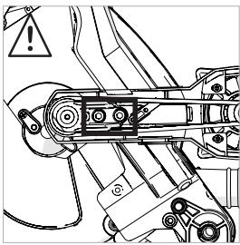
Tensioning the belt:
- To gain access to the transmission case remove the plastic case cover by unscrewing the three (3) machine head bolts which hold it in place with the supplied 4mm Hex Key. (Fig. 72)
- Loosen the four (4) socket headed screws which secure the motor in place. (Fig. 73)
- The tensioning screw (Fig. 74) is accessed through a hole in the rear of the aluminium transmission case with the supplied 4mm Hex Key.
- Use the supplied 4mm Hex Key to turn the tensioning screw in the required direction, clockwise to increase the tension, counterclockwise to reduce the tension.
- Place a finger underneath the drive belt and gently push upwards to discern the tension.
- The belt should be fairly taut over the two drive pulleys, with approximately 3mm (1/8in) deflection detectable either side of the belt at the midpoint between the pulleys. (Fig. 75)
- When the belt tension is correct, tighten the four (4) socket headed screws and replace the transmission case cover.
REPLACING THE DRIVE BELT
Note: Should the belt need replacing, a genuine replacement belt can be purchased by contacting the appropriate customer services on page 3 of this manual.
Replacing the belt:
- To gain access to the transmission case remove the plastic case cover by unscrewing the three (3) machine head bolts which hold it in place with the supplied 4mm Hex Key. (Fig. 72)
- Loosen the four (4) socket headed screws which secure the motor in place. (Fig. 73)
- Remove all tension from the motor by turning the tensioning screw (Fig. 74) counterclockwise.
- Remove the drive belt.
- Thread a new drive belt onto the two pulleys, ensuring that the 'V's' in the belt fit into the 'V's' machined in the pulleys, and that the belt fits fully across the width of both pulleys.
Tension the belt as described in the Tensioning the Belt' section.
- Replace the transmission case cover.
(6.4) ENVIRONMENTAL PROTECTION
Waste electrical products should not be disposed of with household waste. Please recycle where facilities exist. Check with your Local Authority or retailer for recycling advice.


ASSEMBLY SAFETY CHECKS
| PART | CONDITION | YES |
| Slide Carriage | Inserted through the bevel neck and connected to the cutting head. Locating pins successfully deployed. | |
| Mitre Handle Locking Knob | Installed into metre handle / rotary table. | |
| Slide Carriage locking screw | Inserted into the threaded hole in the bevel neck. Anti-vibration spring fitted beneath the locking screw hand knob. | |
| Power Cable | Routed correctly with cable guide/clamps correctly installed. | |
| Blade | Blade correctly installed and with the rotation arrows on the blade and on the machine matching. Outer blade flange and arbor bolt correctly fitted. | |
| Safety Guards | Lower Safety Guard fully operational. Cutting head locks in the upper position with blade covered. Cutting head can only be lowered when Blade Guard Locking Lever is operated. | |
| Supply | Supply matches specification found on machine Rating Plate. Plug matches power source outlet. | |
| Mounting | Either:
a) Machine permanently sited and bolted to workbench.
b) Machine mounted on board which can be clamped to workbench.
c) Machine is bolted to a dedicated metre saw Stand. | |
| Sited | Adequate provision made for the handling of long or irregular shaped work-pieces. | |
| Environment | Dry, clean and tidy. Temperature conducive to material handling. Lighting adequate (double banked if fluorescent lights are used). | |
All the Yes Boxes must be ticked before the machine can be used. No tick = No use.
FINAL SAFETY CHECKS
| PART | CONDITION | YES |
| Assembly | Repeat the Assembly Safety Checks. | |
| Operation | With the machine switched off and disconnected from the mains supply, carry out the following procedures:
· Set the machine to each of its maximum operational settings in turn.
· At each setting lower the cutting head to its lowest position, observing the path of the blade as you do so.
· Check that the blade does not interfere or strike any part of the machine, castings or guards as the cutting head is lowered.
· Check that when the sliding carriage is employed no contact between the cutting head and the blade and other parts of the machine occurs.
· Spin the blade by hand (it is advisable to wear gloves whilst doing this, but not when the saw is being used operationally).
· Check that the blade rotates smoothly with no unusual noises, and that there is no contact between the blade and the upper and lower blade guards.
· Check that there is no discernible blade 'wobble' in any direction as the blade rotates. | |
All the Yes Boxes must be ticked before the machine can be used. No tick = No use.

The manufacturer of the product covered by this Declaration is:
UK: Evolution Power Tools Ltd. Venture One, Longacre Close, Holbrook Industrial Estate, Sheffield, S20 3FR.
FR: Evolution Power Tools SAS. 61 Avenue Lafontaine, 33560, Carbon-Blanc, Bordeaux, France.
The manufacturer hereby declares that the machine as detailed in this declaration fulfils all the relevant provisions of the Machinery Directive and other appropriate directives as detailed below. The manufacture further declares that the machine as detailed in this declaration, where applicable, fulfils the relevant provisions of the Essential Health and Safety requirements.
The Directives covered by this Declaration are as detailed below:
2006/42/EC Machinery Directive.
2014/30/EU. Electromagnetic Compatibility Directive.
2011/65/EU. & The Restriction of the Use of certain
2015/863/EU. Hazardous Substances in Electrical Equipment (RoHS) Directive.
2012/19/EU. The Waste Electrical and Electronic Equipment (WEEE) Directive.
EN 62841-1:2015·EN 62841-3-9:2015/A11:2017·EN 55014-1:2017·EN 55014-2:2015·
EN 61000-3-2: 2014 • EN 61000-3-3: 2013 • EN ISO 12100:2010 • EN 50581:2012
Product Details
Description: 255MM TCT DOUBLE BEVEL SLIDING MITRE SAW
Evolution Model No: R255SMS-DB: 053-0001 / 053-0002 / 053-0003
R255SMS-DB+: 053-0001A / 053-0002A / 053-0003A
Brand Name: EVOLUTION
Voltage: 220-240V 50 Hz - UK, EU & AU
110V\~50Hz-UK
120V~60Hz-US
Input: 2000W (220-240V) / 1600W (110V)
The technical documentation required to demonstrate that the product meets the requirements of directive has been compiled and is available for inspection by the relevant enforcement authorities, and verifies that our technical file contains the documents listed above and that they are the correct standards for the product as detailed above.
Name and address of technical documentation holder.
Signed:

Print: Barry Bloomer
Supply Chain & Procurement Director
Date:
12/11/2018
UK: Evolution Power Tools Ltd. Venture One, Longacre Close, Holbrook Industrial Estate, Sheffield, S20 3FR.
FR: Evolution Power Tools SAS. 61 Avenue Lafontaine, 33560, Carbon-Blanc, Bordeaux, France.
INDICE
Introduccion 41
(UL Std. 987 and CAN/CSA Std.C22.2 No. 71.2)
Warning: Do not stare into the beam.
Wavelength: 650nm
Output Max: ≤ 1mW
CLASS 2 LASER PRODUCT
EN 60825-1:2014
UK: Evolution Power Tools Ltd. Venture One, Longacre Close, Holbrook Industrial Estate, Sheffield, S20 3FR.
FR: Evolution Power Tools SAS. 61 Avenue Lafontaine, 33560, Carbon-Blanc, Bordeaux, France.
UK: Evolution Power Tools Ltd. Venture One, Longacre Close, Holbrook Industrial Estate, Sheffield, S20 3FR.
FR: Evolution Power Tools SAS. 61 Avenue Lafontaine, 33560, Carbon-Blanc, Bordeaux, France.
SOMMAIRE
(UL Std. 987 and CAN/CSA Std.C22.2 No. 71.2)
LASER LIGHT
Warning: Do not stare into the beam
Wavelength: 650nm
Output Max: ≤ 1mW
CLASS 2 LASER PRODUCT
EN 60825-1:2014
MONTAGE PERMANENT DE LA SCIE À ONGLETS

UK: Evolution Power Tools Ltd. Venture One, Longacre Close, Holbrook Industrial Estate, Sheffield, S20 3FR.
FR: Evolution Power Tools SAS. 61 Avenue Lafontaine, 33560, Carbon-Blanc, Bordeaux, France.
2006/42/CE Directive Machines.
UK: Evolution Power Tools Ltd. Venture One, Longacre Close, Holbrook Industrial Estate, Sheffield, S20 3FR.
FR: Evolution Power Tools SAS. 61 Avenue Lafontaine, 33560, Carbon-Blanc, Bordeaux, France.
EVOLUTION®
evolutionpowertools.com
AUS
Total Tools (Importing) Pty Ltd
20 Thackray Road
Port Melbourne
Vic 3207
T:0392611900
FR
Evolution Power Tools SAS
61 Avenue Lafontaine
33560, Carbon-Blanc
Bordeaux
T: +33 (0)5 57 30 61 89
UK
Evolution Power Tools Ltd
Venture One, Longacre Close
Holbrook Industrial Estate
Sheffield, S20 3FR
T: +44 (0)114 251 1022
USA
Evolution Power Tools LLC
8363 Research Drive
Davenport, IA
52806
T: 1-833-MULTI SAW (TOLL FREE)
DE +44 (0)114 251 1022
ES +34 91 114 73 85
NL +44 (0)114 251 1022
PL +48 33 822 09 22
PT+34911147385
RO + 44(0)1142050458
RU +33 (0)5 57 30 61 89
TR +90 (0) 312 9001810


EPT QR CODE