USER MANUAL LC-132 ZIBRO
natural_image
Exterior view of a modern electric heater with digital display and ventilation grille (no text or symbols visible)
GB OPERATING MANUAL.....PAGE 2
PT MANUAL DE INTRUÇÕES .....PAGE 74
DK BRUGERVEJLEDNING ..... PAGE 86
NO BRUKERINSTRUKSEN .....PAGE 98
SE BRUKSANVISNING.....PAGE 110
FI KÄYTTÖOHJEET ......PAGE 122
(This product is not suitable for primary heating purpose)
1 Children should be supervised to ensure that they do not play with the appliance.
2 DO NOT move the heater when it is burning or still hot. DO NOT refill nor service the heater when it is burning or still hot.
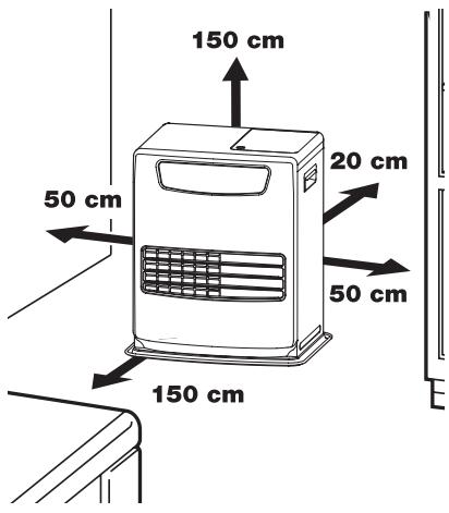
3 Position the front of the heater at a distance of minimum 1.5 metres from walls, curtains, and furniture.
4 DO NOT use the heater in dusty rooms. You will not have optimum burning in such rooms. DO NOT use the heater in the immediate surrounding of a bath, a shower or a swimmingpool.
5 Switch off the heater, before you leave or go sleeping. Unplug the heater as well, when you go away for a longer period of time (e.g. holidays).
6 Store and move fuel only in suitable tanks and jerrycans.
7 Make sure that the fuel is not exposed to heat or extreme temperature changes. ALWAYS store the fuel in a cool, dry and dark place (sunlight will affect the quality).
8 NEVER use the heater in places where harmful gasses or fumes may be present (e.g. exhaust gasses or paint fumes).
9 Beware that the grid of the heater becomes hot. If the appliance is covered there is a risk of fire.
10 ALWAYS make sure that there is sufficient ventilation.
11 The heater must not be located immediately below a socket-outlet.
12 Children of less than 3 years should be kept away unless continuously supervised. Children aged from 3 years and less than 8 years shall only switch on/off the appliance provided that it has been placed or installed in its intended normal operating position and they have been given supervision or instruction concerning use of the appliance in a safe way and understand the hazards involved. Children aged from 3 years and less than 8 years shall not plug in, regulate and clean the appliance or perform user maintenance.
CAUTION - Some parts of this product can become very hot and cause burns. Particular attention has to be given where children and vulnerable people are present.
13 Children shall not play with the appliance.
14 Cleaning and user maintenance shall not be made by children without supervision.
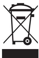
Defective electrical devices and batteries must be kept separate from household waste. Ensure that there is effective recycling where possible. Ask you local council or dealer for expert advice on recycling.
Thank you for choosing a "TOYOTOMI" product!
Toyotomi products are used by satisfied customers worldwide. In order to assure the comfortable and safe use of our products by customers in each country, our products conform to the safety standards not only in Japan but also in every country around the world we do business with.
Toyotomi tailors its products to satisfy its customer's needs by always pursuing our business philosophy, "sharing joys in daily living". We will continue to research, develop and manufacture products that match people's lifestyle for efficiency, safety and comfort.
We hope that you'll enjoy your Toyotomi appliance for years to come! We invite you to read this instruction manual first, to ensure the maximum lifetime for this appliance.
Get to know us better... visit us at www.toyotomi.eu for our full line of products.
1 READ THE DIRECTIONS FOR USE FIRST.
2 IN CASE OF ANY DOUBT, CONTACT YOUR DEALER.
3 BEFORE YOU START READING, CONSULT THE MAIN COMPONENTS LIST ON THE LAST PAGE.
GENERAL DIRECTIONS FOR USE
Below you will find the main steps to be taken for using your heater. For more details, please refer to the MANUAL.
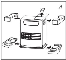
1 Remove all packaging materials (refer to Section A, Fig. A).
2 Fill the removable tank ⑥ (refer to Section B, Fig. C).
3 Insert the plug into the wall-socket.
4 Ignite the heater using the ⏻ key 12 (refer to Section E).
5 If required, change the temperature using the adjustment keys (refer to Section F).
6 Switch off the heater by pressing the ⏻ key 12.
- As a fire precaution, the tank must be filled either when the heater has been switched off or in another room than the room where the heater is installed.
- Always ensure that the tank is closed properly after filling it at a safe distance from all sources of heat and open flames (see Section B).
- The first time the heater is ignited it will smell like "new" for a short time.
- Store all fuel containers with their original caps and seals in a cool and dark place.
- Fuel ages. Use new fuel at the start of every heating season.
- Only use high quality and water-free pure paraffin in accordance with local legislation (TOYOTOMI fuel).
- Before changing brands and/or types of fuel make sure that the mobile heater first completely empties all of the remaining fuel inside the heater.
WHAT YOU NEED TO KNOW IN ADVANCE
VENTILATE SUFFICIENTLY
Read this user manual carefully before using the appliance and keep it for future reference. Install this device only when it complies with local/national legislation, ordinances and standards. This product is intended to be used as a heater in residential houses and is only suitable for use in dry locations, in normal household conditions, indoors in living room, kitchen and garage.
For comfortable and safe heating ensure that there is sufficient ventilation.
NOTE: To avoid unexpected shut off, we recommend to put a door or window ajar when the heater is operating.
Regardless of the model, you must always make sure that the heater is used in a room large enough to enable the heater to be used safely without extra ventilation (refer to Section P). If the room is smaller than required, you must always open a door or window slightly (ensuring an opening of approx. 2.5 cm). It is important that every room where the heater is used has sufficient air intake and efficient air outflow (both openings must have a minimum cross section of 50 cm ^4 ).
We also recommend doing this in highly insulated or draught-free rooms and/or at high altitude. Do not use your heater in cellars or other underground areas.
No modifications to the safety system are allowed, as that will invalidate the guarantee that the air probe will work properly. Consult your dealer in case of doubt.
ESPECIALLY FOR FRANCE: Your heater was designed to operate exclusively on fuel for liquid fuel-operated mobile heaters in accordance with the Decrees of 18-07-2002 and 25-06-2010. The use of other fuels is forbidden.
Ask your dealer or check our website for the addresses of our retailers.
The liquid fuel-operated mobile heater is intended as an extra heater, and not as a continuous source of heat.
ESPECIALLY FOR UNITED KINGDOM: Only use Class C1 paraffin fuel in accordance with BS2869; Part 2, or equivalent.
The user must comply with the following instructions for proper use:
DO NOT
- use the liquid fuel-operated mobile heater in caravans, boats, and vehicle cabins.
- use the liquid fuel-operated mobile heater in insufficiently ventilated rooms (consult the table of properties for the minimum dimensions of the room to be heated), underground rooms and / or at a height of over 1900 metres.
- modify the heater safety features.
The use of this type of heating in public rooms is subject to prior regulatory permission. Obtain proper information on this in advance.
THE RIGHT FUEL
Your heater has been designed for use with high-quality water-free pure paraffin oil (TOYOTOMI fuel). Only fuels of this kind will ensure clean and proper burning. Lower quality fuel may result in:
- increased possibility of malfunctioning
- incomplete combustion
- reduced heater lifetime
- smoke and/or fumes
- deposits on the grid or mantle
Using the right fuel is therefore essential for safe, efficient, and comfortable use of your heater.
Damage and/or malfunctions of the heater due to the use of other than high-quality water-free pure paraffin oil is not covered by the warranty.
Always refer to (www.toyotomi.eu) for the right fuel for your heater.
Only the use of the correct fuel will ensure safe, efficient, and comfortable use of your heater.

This transportation cap is packed separately in the box. Only this cap ensures trouble-free transportation of the heater after use. Store it well!
MANUAL
A INSTALLING THE HEATER
1 Carefully remove your heater from the box and check the contents. In addition to the heater you also need to have:
- a manual fuel pump
● a transportation cap
● these directions for use
Keep the box and the packaging materials (Fig. A) for storage and/or transportation.
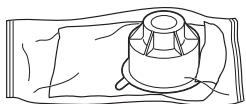
2 Open the lid of the removable tank ④ and remove the piece of cardboard.
3 Fill the removable tank as indicated in Section B.
4 The floor should be firm and completely level. Reposition the heater, when it is not level. Do not try to correct the situation by placing books or other goods under the heater.
5 Insert the plug 10 into the wall-socket (230 Volts - AC / 50 Hz) and set the correct time using the adjustment keys 14 (refer to Section C).
6 Your heater is now ready for use.
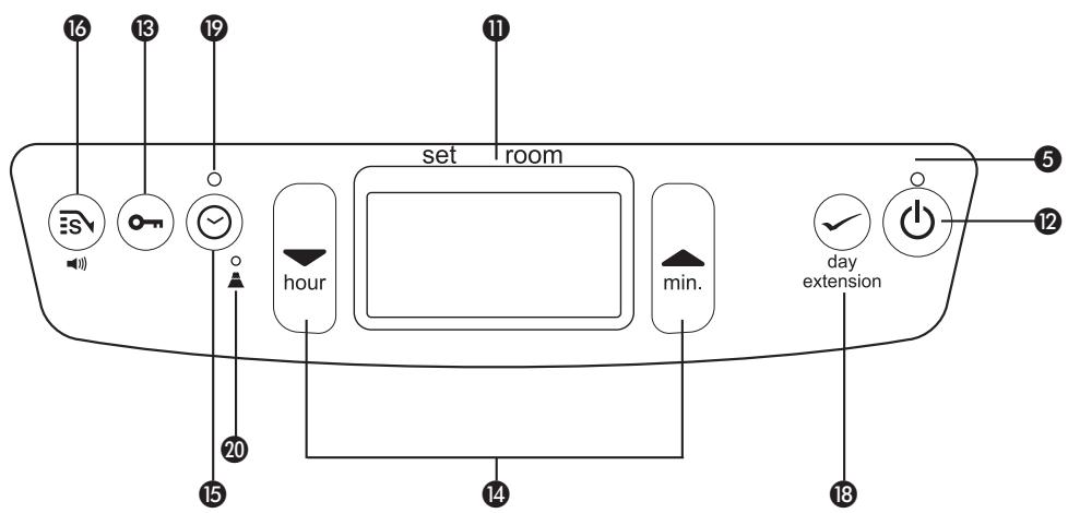
SET ALTITUDE
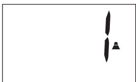
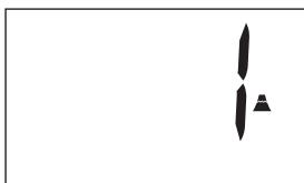
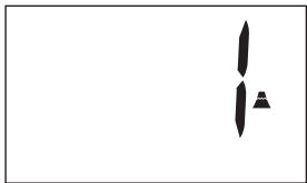
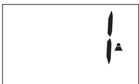
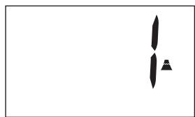
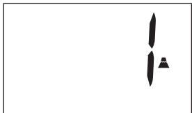
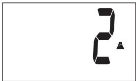
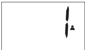
1 If the heater is used at a height of 800 m to 1300 m, use the altitude mode 1. Push the altitude button 20 with thin rod like a clip and plug into the outlet simultaneously. Then “/▲” will be shown on the display.
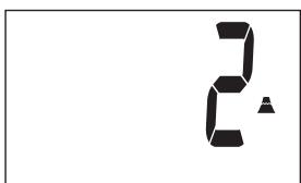
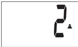
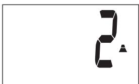
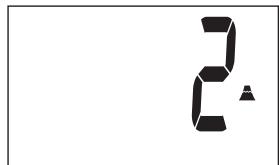
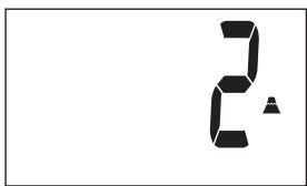
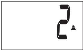
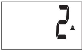
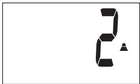
2 If the heater is used at a height of 1300 m to 1900 m, use the altitude mode 2. After setting the altitude mode 1, push the altitude button 20 with thin rod and plug into the outlet simultaneously again. Then “2” will be shown on the display.
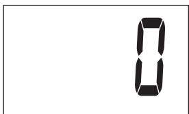
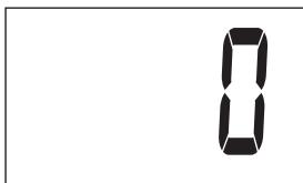
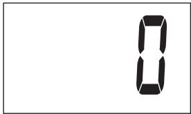
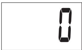
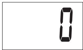
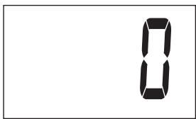
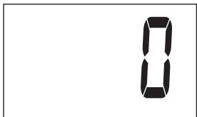
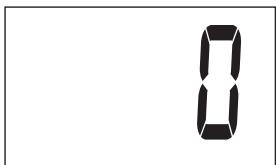
3 Switch off the altitude mode by pressing the altitude button 20 and into the outlet simultaneously after setting altitude mode 2. Then “☐” will be shown on the display and “▲” will be disappeared.
NOTE: When the altitude mode 1 is set, the altitude mark “▲” is lit on the display. When the altitude mode 2 is set, the altitude mark “▲” is blinking during operation.
NOTE: In the event of power failure or disconnection of heater, the altitude setting will remain.

Do not use the heater at a height of over 1900 meters.
SWITCH THE VOLUME
This heater can be switched the buzzer sound volume. The initial setting is in High level.
1 Push the SAVE key 16 and holding it down for more than 3 seconds, then the buzzer sound volume is switched from High to Low.
2 Push the SAVE key 16 and holding it down for more than 3 seconds again, then the buzzer sound volume is switched from Low to High.
NOTE: The volume level is Low and High only, but the alarm by safety device sounds in High level.
NOTE: When the heater has been unplugged or after a power failure, the volume will be the initial setting High.
flowchart
graph TD
    A["Fan"] --> B["Printer"]
    B --> C["Printer"]
    C --> D["Printer"]
    D --> E["Printer"]
    E --> F["Printer"]
    F --> G["Printer"]
    G --> H["Printer"]
    H --> I["Printer"]
    I --> J["Printer"]
    J --> K["Printer"]
    K --> L["Printer"]
    L --> M["Printer"]
    M --> N["Printer"]
    N --> O["Printer"]
    O --> P["Printer"]
    P --> Q["Printer"]
    Q --> R["Printer"]
    R --> S["Printer"]
    S --> T["Printer"]
    T --> U["Printer"]
    U --> V["Printer"]
    V --> W["Printer"]
    W --> X["Printer"]
    X --> Y["Printer"]
    Y --> Z["Printer"]
    Z --> AA["Printer"]
    AA --> AB["Printer"]
    AB --> AC["Printer"]
    AC --> AD["Printer"]
    AD --> AE["Printer"]
    AE --> AF["Printer"]
    AF --> AG["Printer"]
    AG --> AH["Printer"]
    AH --> AI["Printer"]
natural_image
Line drawing of a hand inserting a component into a device (no text or symbols)
natural_image
Simple black line drawing of a pen and triangle on white background (no text or symbols)
B FILLING FUEL
Fill the removable tank in a suitable place since there can always be some spillage. Follow the procedure below:
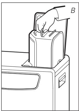
1 Make sure that the heater is switched off.
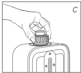
2 Open the upper lid and lift the removable tank out of the heater (Fig. B). Put down the removable tank (cap pointing upwards, handle on floor) and screw off the fuel cap (Fig. C).
NOTE: Some drops may leak from the tank.
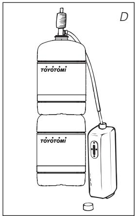
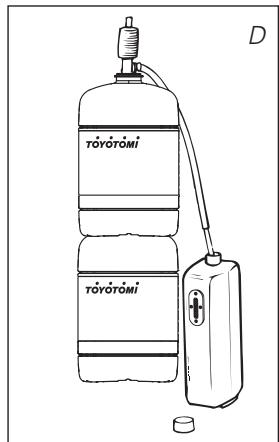
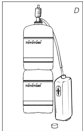
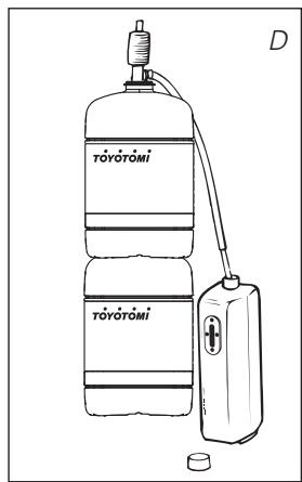
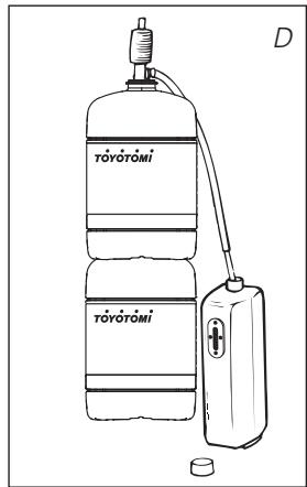
3 Fill the removable tank using a fuel pump (refer to fuel pump operation instructions.) Make sure that it is in a higher position than the removable tank (Fig. D). Insert the ribbed hose into the opening of the removable tank.
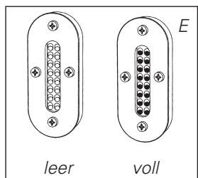
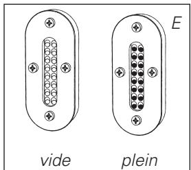
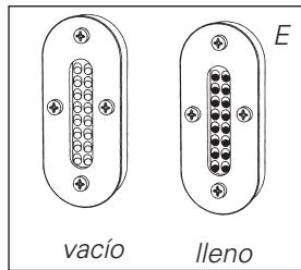
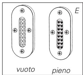
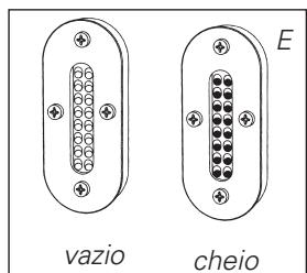
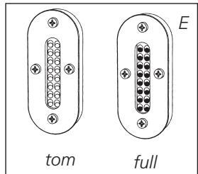
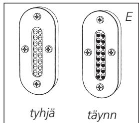
4 Check the removable tank fuel gauge while filling the tank (Fig. E). Stop filling once the gauge indicates that the tank is full. Never overfill the tank, especially not when the fuel is very cold (fuel expands when it heats up).
5 Let the remaining fuel in the pump flow back into the jerrycan and carefully remove the pump. Carefully screw the fuel cap back on the tank. Clean off any spilled fuel.
6 Check whether the fuel cap is straight and tightened properly. Reinstall the removable tank in the heater (cap down). Close the lid.
C SETTING THE CLOCK
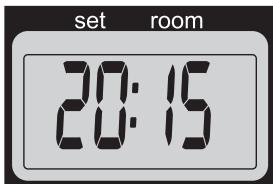
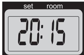
It is only possible to set the correct time, when the heater is connected to the mains and not burning. Use the adjustment keys ⑭ to set the time. First press either of the two keys to switch on the function (the 4-digit ⑪ will start blinking). Next, set the hours using the key on the left ( ▼ hour) and the minutes using the key on the right ( ▲ min.). Press once to increase the value by one step. When you hold down the key, the value will continue going up, until you release the key again. After approximately 10 seconds the 4-digit will stop blinking and the setting will be locked (Fig. F). 5 minutes after switching off the heater, the information on the display will disappear and the heater will automatically switch into the stand-by position.
When the heater has been unplugged for more than 30 minutes (or after a power failure), the time and the day need to be set again.
D WEEKLY TIMER
Here is an example on how the weekly timer can be programmed:
| Monday | Tuesday | Wednesday | Thursday | Friday | Saturday | Sunday |
| P1 ON | 6:30 | 6:30 | 6:30 | 6:30 | 6:30 | 10:00 | 9:00 |
| P1 OFF | 8:45 | 8:45 | 8:45 | 8:45 | 8:45 | 23:00 | 23:00 |
| P2 ON | 12:00 | 15:00 | 18:00 | 12:00 | 12:00 | | |
| P2 OFF | 14:00 | 23:00 | 23:00 | 14:00 | 14:00 | | |
| P3 ON | 18:00 | | | 18:00 | 18:00 | | |
| P3 OFF | 23:00 | | | 23:00 | 23:00 | | |
• Maximum of 3 programs per day can be set.
- Every day of the week can be programmed separately.
• Minimum switching interval, 1 hour.
• Minimum activation time, 1 hour.
- Choice between manual and timer.
- Settings are saved in the memory and remain saved without power supply.
natural_image
Line drawing of a hand holding a knob on a device component (no text or symbols)

F: When the 4-digit stops blinking, the setting has been locked to the indicated value.
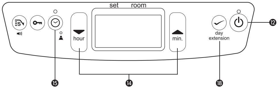
Make sure the heater is connected to the mains and not burning. Press the timer-key 15. Also make sure the time and day are set correctly. Choose the day you would like to program by pressing the adjustment keys 14. Press the adjustment key ▲ to increase the day by one step and press the key ▼ to decrease the day.
Press extension/day/set 18 to select the desired day. The display shows:
With the adjustment keys ▲ and ▼ 14 you can choose between the programs P1, P2 and P3. You can also choose the option Copy to copying the setting from one day to another. Press extension/day/set 18 to select the displayed program.
Use the adjustment keys 14 to set the hour at which the heater must ignite. Press the adjustment key ▲ to increase the hour and the key ▼ to decrease the hour. Press extension/day/set 18 to select the right hour.
Then, use the adjustment keys 14 to set the minute. Press the adjustment key ▲ to increase the minute and the key ▼ to decrease the minute. Press extension/day/set 18 to select the right minute.
Use the adjustment keys 14 to set the hour at which the heater must shut off.
Press the adjustment key ▲ to increase the hour and the key ▼ to decrease the hour.
Press extension/day/set 18 to select the right hour.
Then, use the adjustment keys 14 to set the minute. Press the adjustment key ▲ to increase the minute and the key ▼ to decrease the minute. Press extension/day/set 18 to select the right minute.
The settings for program 1 for Monday are programmed and the display shows SET for 3 seconds.
After 3 seconds choose another day or end the setting mode by pressing timer.
Press the "timer" key 15 to exit the weekly timer setting mode and return to the time and a day of the week display. Timer lamp turns off.
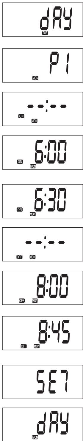
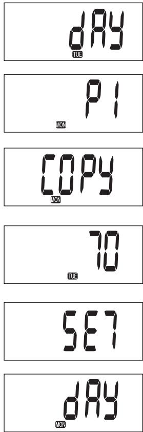
COPYING THE SETTING FROM ONE DAY TO ANOTHER
Use the copy function if there are multiple days during one week which should have the same setting times.
Make sure that the heater is not burning. Press the timer key 15. Use the adjustment keys 14 until the day of its source is displayed in the display.
Press extension/day/set 18 to select.
The display shows:
Use the adjustment keys ▲ or ▼ 14 to choose copy. Press extension/day/set 18 to select the copy function.
Use the adjustment keys ▲ or ▼ 14 to select the day to which the settings should be copied. Press extension/day/set 18 to choose the selected day.
The settings for program for Tuesday are programmed and the display shows SET for 3 seconds.
After 3 seconds choose another day to copy or end the setting mode by pressing timer.
Switch on the heater by pressing the POWER button 12. And then press the timer-key 15 immediately after that. The Timer light will light up and the heater shuts off. The On / Off indicators on the display shows whether the appliance is switched on or off.
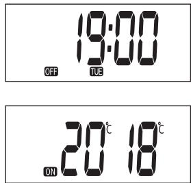
When the appliance is switched off by the timer, the off indicator is visible. The display shows the -actual time.
When the appliance is switched on by the timer, the on indicator is visible. The display shows the desired (set) and actual (room) temperature.
E IGNITING THE HEATER
When used for the first time, a new heater may give out a smell for a short while.
You should therefore provide extra ventilation.

Always ignite the heater with the ⏻ button ⑫. Never use matches or a cigarette lighter.
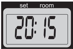
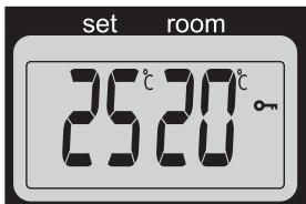
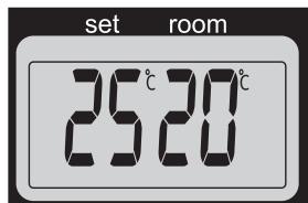
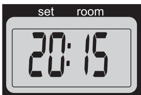
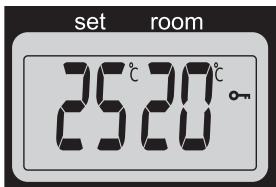
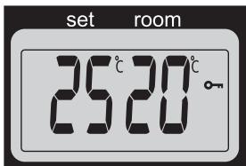
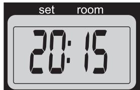
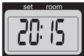
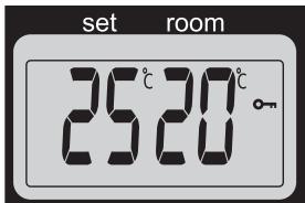
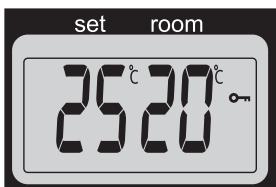
Just press the ⏻ button ⑫ to ignite the heater. The POWER lamp will start blinking, indicating that the ignition procedure has started. This will take a short while. Once the heater is burning, the POWER lamp will remain lit (red). The information display ⑪ will show two numbers. The light next to them indicates that these numbers refer to the temperatures (Fig. G). The actual room temperature is indicated below ROOM, while the temperature setting is indicated below SET. The latter can be changed with the adjustment keys (refer to Section F).
Prior to igniting the heater, always check for sufficient fuel in the removable tank.
G: The required temperature on the left, the measured temperature on the right.
F SETTING THE REQUIRED TEMPERATURE
The temperature setting can only be adjusted, when the heater is burning. Use the adjustment keys 14 to adjust the temperature. First press either of the two keys to switch on the function (the °C mark 11 will start blinking). Next, adjust the temperature using the key on the right (▲min.) to set the temperature to a higher setting and the key on the left (▼hour) to lower the temperature. Press once to increase the value one step. After approximately 10 seconds the °C mark will stop blinking and the setting will be locked (Fig. G).
The available temperature settings range from 6^ C minimum to 28^ C maximum. When the heater has been unplugged (or after a power failure), the temperature will reset to the factory setting of 20^ C.
G SWITCHING OFF THE HEATER
There are two ways to switch off the heater.
1 Press the ⏻ button 12. The information display will show the CLOCK signal. Within approximately one minute the flame will have extinguished.
2 Press the TIMER key 15, when you want to switch off the heater and ignite it again with the timer the next time. This not only switches off the heater, but it also activates the timer function.
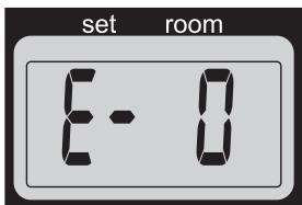
The information display ⑪ not only serves as an indicator of the (set) time and temperature (Sections C, D, and F), it also indicates any malfunctioning of the heater. The code on the information display tells you what is the matter:
| CODE | INFORMATION | WHAT TO DO |
| E-0 | Temperature within the heater too high. | Cool-down and re-ignite. |
| F-0 | Power interrupted. | Re-ignite the heater. |
| E-1 | Faulty thermostat. | Contact your dealer. |
| F-1 | Faulty burner thermistor. | Contact your dealer. |
| E-2 | Starting problems. | Contact your dealer. |
| E-23 | Re-ignite the heater immediately after extinguishing. | Wait for approx. 30 sec.and re-ignite after inserting the plug again. |
| E-5 | Tipping-over protection. | Re-ignite the heater. |
| E-6 | Poor burning. | Contact your dealer. |
| E-7 | Room temperature above 32°C. | If necessary,re-ignite the heater. |
| E-8 | Defective booster. | Contact your dealer. |
| E-81 | Abnormal frequency. | Insert the plug into the wall-socket again.Contact your dealer. |
| E-9 | Air filter dirty; or Fuel pump dirty. | Clean filter.Contact your dealer. |
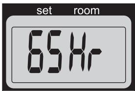
| 65 Hr | The heater has been in operation continuously for a period of 65 hours and has turned itself off automatically. | Switch the heater back on. |
| --: --+ | Out of fuel. | Refill removable tank. |
| --: --+ | Too little ventilation. | Ventilate better. |
In case of any malfunctioning the information display will tell you what is the matter.
Always contact your dealer for any malfunctioning not listed above and/or when the error keeps occurring after taking the corrective measure as described above.
AUTOMATIC DEACTIVATION
This heater is fitted with a safety system that ensures that it switches off automatically after 65 hours continuous operation. The following will then appear in the display:65 Hr. If desired, you can switch the heater on again by pressing the ⏻ button ⑫ (see Section E).
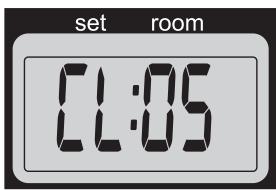
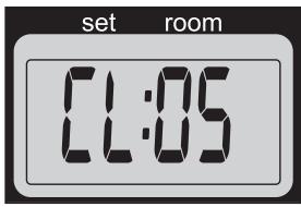
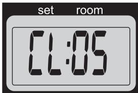
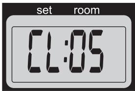
AUTOMATIC CLEANING MODE
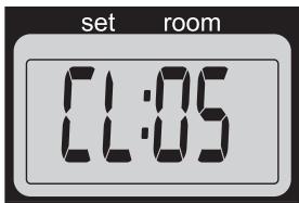
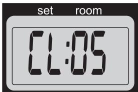
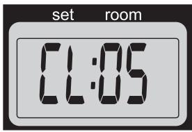
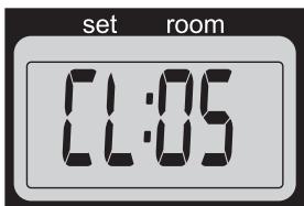
When the heater has been burning continuously for two hours at its highest setting, the burner will automatically start an autoclean procedure. The display will show the autocleaningcode CL:OS running back to CL:OI. The procedure takes 5 minutes, during which the heater will burn at its lowest setting, while the burner autocleans. When the burner is clean again, the heater will automatically switch back to the highest setting again.
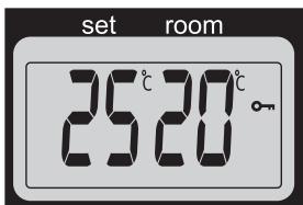
CHILDPROOF LOCK / PARENTAL CONTROL
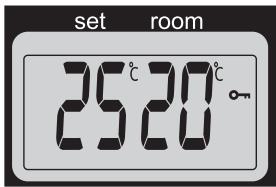
The childproof lock can be used to prevent children accidentally changing the heater settings. When the heater is burning and the childproof lock is on, the heater can only be switched off. Other functions are blocked then. If the heater has already been switched off, the childproof lock also prevents accidental ignition of the heater. Activate the childproof lock by pressing the appropriate key 13 and holding it down for more than 3 seconds. The KEY-LOCK indicator will appear on the information display (Fig. I), indicating that the childproof lock has been activated. Switch off the childproof lock by pressing the key 13 and holding it down for more than 3 seconds once again.
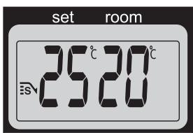
J THE CORRECT USE OF 'SAVE'
The 'SAVE' function allows you to limit the temperature. When this function is activated, the heater will automatically switch off, when the room temperature exceeds the set temperature by 3°C. Subsequently, when the room temperature has dropped again to the set temperature, the heater will automatically switch on again. Activate the 'SAVE' setting by pressing the appropriate 16 key. The SAVE indicator light will light up (Fig. J). Switch off the function by pressing the SAVE key once again.

Without the 'SAVE' setting your heater will maintain the set temperature by approximation as well, by adjusting its heating capacity. 'SAVE' is an economy setting, which you can use when, for instance, you are not present in the room or to keep it frost-free.
K THE 'FUEL' INDICATOR
When the FUEL indicator appears, it means that there is only fuel left for 10 more minutes. The count-down of the remaining heating time can be seen in the information display ⑪ (Fig. K). Now you have two options:
- you remove the fuel tank and refill it outside the living room (Section B) or
- you push the button extension 18. By pushing this button, the remaining heating time will extend to 60 minutes.
The heater will automatically switch back to its lowest position. In the display the number 60 will appear, which will decline to 10. At the arrival of 10, you will hear an alarm signal every two minutes, warning you to refill the removable tank. If you do not react, the heater will extinguish by itself. The heater will also sound a warning signal, when it switches off. The fuel indicator will blink, while four lines (--:--) are blinking in the information display. You can stop this by pressing the ⏻ button ⑫ once more.
Once the heater has used up all its fuel and extinguished, it will take some time, after the refill, before the heater is completely ready for use again.
L THE 'VENT' INDICATOR
When the VENT indicator starts blinking, this is a sign that the room is not vented sufficiently (Fig. L). The heater will switch off automatically. If the indicator continues blinking after extra ventilation, please contact your dealer..
I: When the ⏻ mark appears, the childproof lock has been activated.
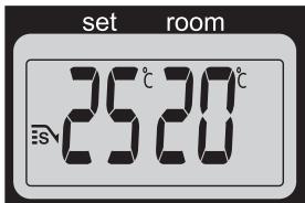
J: When the SAVE light lights up, the heater will automatically switch on or off in order to remain within a specified temperature range.
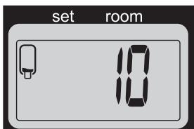
K: When the FUEL indicator has appeared, the information display will show the number of minutes of fuel left in the tank.
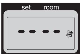
L: A blinking VENT indicator is a sign that you need extra ventilation.
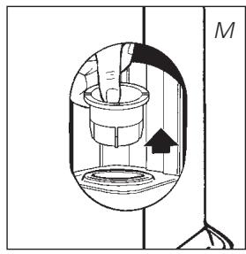
M MAINTENANCE
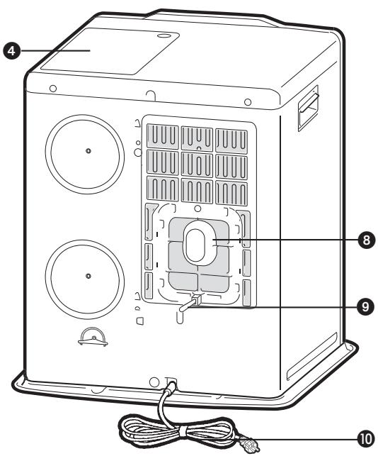
Switch off the heater and let it cool down, before you start any maintenance work. Also disconnect the plug from the mains. Your heater needs hardly any maintenance. It is, however, important that you clean the vent filter ⑧ with a vacuum cleaner and the grid ② with a damp cloth, both on a weekly basis. Regularly inspect the fuel filter as well:
1 Remove the removable tank ⑥ from the heater and remove the fuel filter (Fig. M). Some drops may leak from the filter; keep a cloth at hand.
2 Remove the dirt by tapping the fuel filter upside-down against a hard surface. (Never clean it with water!)
3 Reinstall the fuel filter into the heater.
We recommend that you remove dust and stains from time to time with a damp cloth, because otherwise these may cause stains that are hard to remove.

Do not remove any heater components yourself. Always contact your dealer for repairs. When the power cord is damaged, it may only be replaced by an authorised fitter. Use a new cord of the type H05 VV-F.
N STORAGE (END OF THE HEATING SEASON)
At the end of the heating season, you must store the heater in a dust-free place, if possible in its original packaging. Unused fuel cannot be used in the next heating season. We therefore recommend that you burn up all fuel. If there is still some fuel left, do not throw it away, but dispose of it in accordance with the local regulations for the disposal of domestic chemical waste.
Always start the new heating season with fresh fuel. When you start re-using the heater follow the instructions again (starting from Section A and as specified).
O TRANSPORTATION
Take the following measures to avoid fuel leakage during the transportation of the heater:
1 Let the heater cool down.
2 Remove the removable tank ⑥ from the heater and remove the fuel filter (refer to Section M, Fig. M). Some drops may leak from the filter; keep a cloth at hand. Store the fuel filter and the removable tank outside the heater.
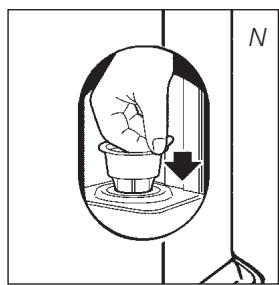
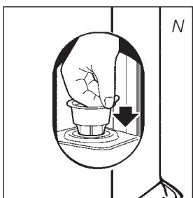
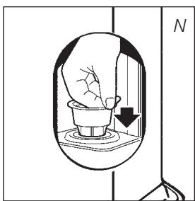
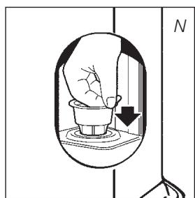
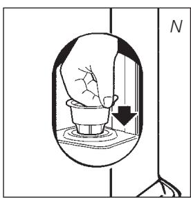
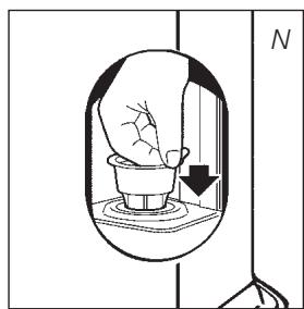
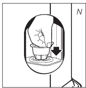
3 Place the transportation cap into the position of the fuel filter (Fig. N). Press it tight. The transportation cap will, as much as possible, prevent oil leakage from the heater during transport.
4 Always move the heater in an upright position.
5 Make the fixed tank empty with a fuel pump before transportation or in case of wrong or dirty fuel. First remove the fuel filter and then insert the fuel pump into the empty fixed tank. Follow the same procedure if the fuel tank contains water.
natural_image
Cross-sectional diagram of a mechanical device with internal components and an arrow indicating direction (no text or symbols)

natural_image
Diagram showing a hand pouring liquid into a cup inside a circular opening, with an arrow indicating direction (no text or symbols)
Transportation cap

| Ignition | electrical | Dimensions (mm) | width | 376 |
| Fuel | paraffin | including base plate: | depth | 296 |
| Capacity (kW) max. | 3.20 | | height | 428 |
| Capacity (kW) min. | 0.80 | Accessories: | - manual fuel pump |
| Suitable space ( m^3 )** | 48-120 | | - transportation cap |
| Fuel consumption (l/hr)* | 0.333 | Mains | | 230 V |
| | | -- AC / 50 Hz |
| Fuel consumption (g/hr)* | 267 | Electrical consumption: | | |
| Burning time per tank (hr)* | 16.2 | - igniter | | 320 W |
| Capacity removable tank (litres) | 5.4 | - continuous | | 13 W |
| Weight (kg) | 8.0 | Fuse rating | | 250V, 5A |
* At maximum setting ** Specified values are indicative
Q WARRANTY PROVISIONS
Your heater comes with a 48-month warranty starting on the date of purchase. Within this period all defects in material or workmanship will be repaired without any charge. The following provisions shall apply regarding this warranty:
1 We expressly dismiss all other claims for damages, including consequential damages.
2 Any repairs or replacements of components within the term of warranty will not result in an extension of the term of warranty.
3 The warranty shall no longer apply, when the heater has been modified, non-original parts have been used, or when it is repaired by third parties.
4 The warranty shall not apply to parts that are subject to normal wear, such as the burner mat, any kind of gasket and the manual fuel pump.
5 The warranty shall only apply, when you present the original, dated proof of purchase, provided no changes have been made to it.
6 The warranty shall not apply to damages caused by actions not in compliance with the Directions for Use, neglect, and the use of an incorrect type of fuel, or fuel past its use-by date. The use of incorrect fuel can even be dangerous*.
7 Transportation costs and the risks involved during the transportation of the heater or heater components shall always be at the expense of the purchaser.
In order to avoid unnecessary costs, we recommend that you always read the
'Directions for Use' carefully first. In case they offer no solution, please take the heater to your dealer for repair.
R PRODUCT FICHE
| (a) Supplier's name/Trademark | TOYOTOMI Europe Sales B.V. |
| (b) Model | LC-132 |
| (c) EEC | A |
| (d) Direct heat output | 3.2kW |
| (e) Indirect heat output | N/A |
| (f) EEI | 96.0% |
| (g) Useful energy efficiency | 100% |
| (h) Specific precaution | For assembly, installation or maintenance instructions, please refer to the operating manual. |
S MAIN COMPONENTS
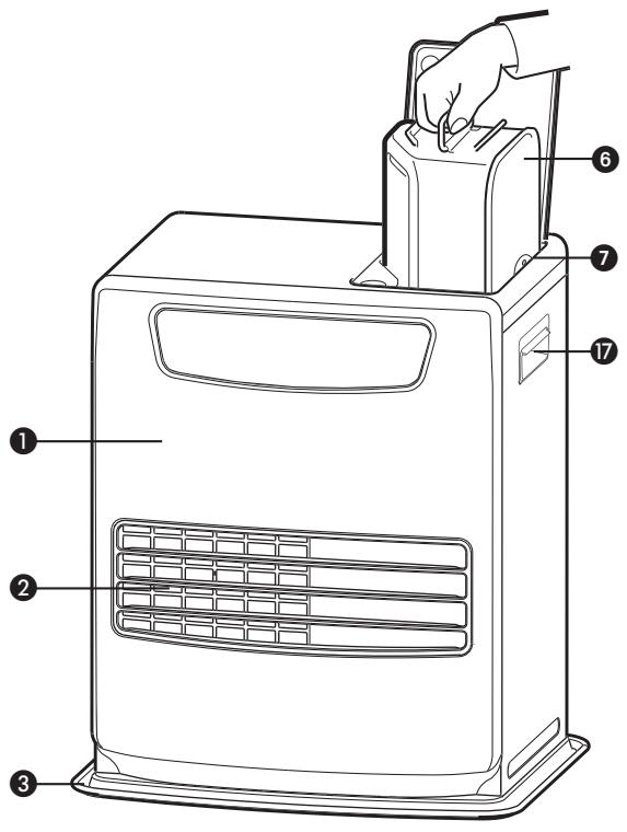


1 Front plate
② Grid
③ Base plate
4 Lid for removable tank
⑤ Operation panel
6 Removable tank
⑦ Fuel gauge removable tank
8 Vent filter
9 Thermostat
10 Plug + cord
11 Information display
12 ⏻ key
13 Childproof lock
14 Adjustment keys (time and temperature)
15 Timer
16 SAVE key
17 Handle
18 Extension / day /set (weekly timer)
19 Timer lamp
20 Altitude setting button
natural_image
Line drawing of a hand inserting a component into a device (no text or symbols)
natural_image
Simple black geometric shapes on white background, no text or symbols present
natural_image
Line drawing of a hand holding a small mechanical component, no text or symbols present

natural_image
Cross-sectional diagram of a mechanical device with internal components and an arrow indicating direction (no text or symbols)

natural_image
Diagram showing a hand pouring liquid into a cup inside an inverted container, with a directional arrow and label 'N' (no text or symbols on the diagram itself)
Transport-verschluß

P
TECHNISCHE DATEN


LE COMBUSTIBLE APPROPRIÉ
natural_image
Line drawing of a hand inserting a component into a device (no text or symbols)
natural_image
Simple black line drawing of a stylized object with two triangular shapes, no text or symbols present

B REMPLISSAGE DU COMBUSTIBLE
natural_image
Line drawing of a hand pressing down on a device component (no text or symbols)
FR
33
VERROUILLAGE DE SECURITE ENFANTS
natural_image
Cross-sectional diagram of a mechanical device with internal components and an arrow indicating direction (no text or symbols)

natural_image
Diagram showing a hand pouring liquid into a cup inside an inverted container, with a directional arrow and label 'N' (no text or symbols on the diagram itself)
Bouchon de transport

O TRANSPORT
CONDITIONS DE GARANTIE


WAT U VOORAF MOET WETEN
ALTIJD VOLDOENDE VENTILEREN
natural_image
Line drawing of a hand inserting a component into a device (no text or symbols)
natural_image
Simple black line drawing of a pen and pencil with a triangular tip, on white background (no text or symbols)
B VULLEN MET BRANDSTOF
natural_image
Line drawing of a hand holding a small mechanical component, no text or symbols present

natural_image
Cross-sectional diagram of a mechanical device with internal components and an arrow indicating direction (no text or symbols)

natural_image
Diagram showing a hand pouring liquid into a cup inside an inverted container, with a directional arrow and label 'N' (no text or symbols on the diagram itself)
Transportdop

P SPECIFICATIES


natural_image
Line drawing of a hand inserting a component into a device (no text or symbols)
natural_image
Simple black line drawing of a stylized object with two triangular shapes, no text or symbols present
B LLENAR DE COMBUSTIBLE
natural_image
Line drawing of a hand holding a small mechanical component, no text or symbols present

J USO CORRECTO DE LA FUNCION 'SAVE'
natural_image
Cross-sectional diagram of a mechanical device with internal components and an arrow indicating direction (no text or symbols)
natural_image
Diagram of a hand pouring liquid into a cup inside an inverted container, with a directional arrow and label 'N' (no text or symbols on the diagram itself)
Tapón de
transporte


ESPECIFICACIONES


natural_image
Line drawing of a hand inserting a component into a device (no text or symbols)

natural_image
Simple black line drawing of a stylized object with two triangular shapes, no text or symbols present

B RIFORNIMENTO DEL COMBUSTIBILE
natural_image
Line drawing of a hand holding a mechanical component with a knob (no text or symbols)

E ACCENSIONE DELLA STUFA
natural_image
Cross-sectional diagram of a mechanical device with internal components and an arrow indicating direction (no text or symbols)


natural_image
Diagram showing a hand pouring liquid into a cup inside a circular opening, with an arrow indicating direction (no text or symbols)

natural_image
Line drawing of a hand inserting a component into a device (no text or symbols)

natural_image
Simple black line drawing of a pen and triangle on white background (no text or symbols)

B ABASTECIMENTO DE COMBUSTÍVEL
natural_image
Line drawing of a hand holding a small mechanical component, no text or symbols present
TECLA DE BLOQUEIO / CONTROLO PARENTAL
natural_image
Cross-sectional diagram of a mechanical device with internal components and an arrow indicating direction (no text or symbols)

natural_image
Diagram showing a hand pouring liquid into a cup inside a circular opening, with an arrow indicating direction (no text or symbols)
Tapón de transporte


natural_image
Line drawing of a hand inserting a component into a device (no text or symbols)
natural_image
Simple black line drawing of a stylized object with two triangular shapes, no text or symbols present

B PÅFYLDNING AF BRÆNDSTOF
natural_image
Line drawing of a hand pressing a button onto a device component (no text or symbols)
DK
AUTOMATISK RENSNING AF BRÆNDER

natural_image
Cross-sectional diagram of a mechanical device with internal components and an arrow indicating direction (no text or symbols)
natural_image
Diagram of a hand pouring liquid into a cup inside an inverted container, with a directional arrow and label 'N' (no text or symbols on the diagram itself)
Transportprop


natural_image
Line drawing of a hand inserting a component into a device (no text or symbols)

natural_image
Simple black line drawing of a pen and triangle on white background (no text or symbols)
B FYLLE DRIVSTOFF
natural_image
Line drawing of a hand pressing a button onto a device (no text or symbols)

F: Når de 4 tallene slutter å blinke, er innstillingen låst med den angitte verdien.

Slå av varmeovnen hvis den står på. Trykk på timerknappen 15. For å kunne aktivere timeren må du ha stilt tiden og dagen riktig. Velg dagen som du vil programmere ved å trykke på 14. Trykk på ▲ én gang for å øke verdien ett trinn. Trykk på ▼ én gang for å redusere verdien ett trinn.
I: Når 🔍-symbolet vises, er barnesikringen aktivert.
K: Når
drivstoffindikatoren
lyser, viser
informasjonsdisplayet
hvor mange minutter
ovnen kan brenne før
beholderen er tom.
L VENTILASJONSINDIKATOREN
natural_image
Cross-sectional diagram of a mechanical device with internal components and an arrow indicating direction (no text or symbols)
natural_image
Diagram showing a hand pouring liquid into a cup inside an inverted container, with a directional arrow and label 'N' (no text or symbols on the diagram itself)
Transportdeksel

| Tenning | elektrisk | Mål (mm) | bredde | 376 |
| Drivstoff | parafin | inkludert bunnplaten: | dybde | 296 |
| Kapasitet (kW) maks | 3,20 | | høyde | 428 |
| Kapasitet (kW) min. | 0,80 | Tilbehør: | - manuell drivstoffpumpe |
| Egnet plass ( m^3 )** | 48-120 | | - transportdeksel |
| Drivstofforbruk (l/t)* | 0,333 | Inngangsstrøm | | 230 V |
| | | -- AC / 50 Hz |
| Drivstofforbruk (g/t)* | 267 | Strømforbruk: | | |
| Forbrenningstid per beholder (t)* | 16,2 | - tenner | | 320 W |
| Kapasitet uttakbar beholder (liter) | 5,4 | - kontinuerlig | | 13 W |
| Vekt (kg) | 8,0 | Sikringsstørrels | | 250V, 5A |


SE ALLTID TILL ATT DET FINNS TILLRÄCKLIG VENTILATION
natural_image
Line drawing of a hand inserting a component into a machine (no text or symbols)
natural_image
Simple black line drawing of a stylized human figure with a triangular base (no text or symbols)

B FYLLA PÅ BRÄNSLE
natural_image
Line drawing of a hand holding a small mechanical component, with no visible text or symbols
AUTOMATISKT RENGÖRINGSLÄGE
natural_image
Diagram showing a hand pouring liquid into a container inside an inverted vise, with a directional arrow and label N (no text or symbols on the diagram itself)
Transportationskydd


natural_image
Line drawing of a hand inserting a component into a device (no text or symbols)

natural_image
Simple black line drawing of a pen and ruler on white background (no text or symbols)
natural_image
Line drawing of a hand holding a small mechanical component, no text or symbols present

J 'SAVE'-TOIMINNON OIKEA KÄYTTÖ

natural_image
Cross-sectional diagram of a mechanical device with internal components and an arrow indicating direction (no text or symbols)
natural_image
Diagram of a hand pouring liquid into a cup inside a container, with an arrow indicating direction (no text or symbols)
Kuljetuskorkki


Distributed in Europe by TOYOTOMI EUROPE SALES B.V.
Should you require further information or should particular problems occur that are not dealt with in this operating manual, please visit our website www.toyotomi.eu or contact our Sales Support (you find its phone number on www.toyotomi.eu)
Kerosun, Toyostove, Toyoset, Toyotomi and Zibro for the use of paraffin heaters are all registered trademarks of TOYOTOMI Co., Ltd. - Japan.
Zibro brand paraffin heaters are made in JAPAN and imported by Toyotomi Europe Sales b.v.