CLAS 90 EIRB/C-EU BLEU - Induction cooktop FALCON - Free user manual and instructions
Find the device manual for free CLAS 90 EIRB/C-EU BLEU FALCON in PDF.
| Product Type | Induction hob with ovens and grill |
| Brand | FALCON |
| Model | CLAS 90 EIRB/C-EU BLUE |
| Width | 900 mm |
| Depth (overall) | 610 mm (above the hob) |
| Height (adjustable) | 905 mm (min) - 932 mm (max) |
| Weight (estimated) | Approximately 80 kg |
| Power supply | 220-240 V ~ 50 Hz |
| Maximum total electrical power | 17.1 kW (fan oven variant) / 18.3 kW (multifunction variant with Rapid Response) |
| Number of induction zones | 5 |
| Zone diameters | Front left: 14 cm; Rear left: 18 cm; Center: 18 cm; Rear right: 18 cm; Front right: 14 cm |
| Main cooking functions | Induction with automatic heating, child lock, pan detection, residual heat indicator |
| Main oven type | Fan oven or Multifunction (depending on model) |
| Top oven type | Fan oven |
| Grill power | 2.3 kW |
| Energy efficiency class (main oven) | A (convection) / B (multifunction) |
| Hob maintenance | Semi-liquid cleaner for ceramic glass, scraper for sugary spills |
| Safety | Automatic shut-off, overheating protection, child lock, residual heat indicator |
| Common spare parts | Oven bulb (15 W, Edison base 240 V, resistant to 300 °C) |
| Included accessories | Racks, drip tray, sliding grill, handles |
Frequently Asked Questions - CLAS 90 EIRB/C-EU BLEU FALCON
User questions about CLAS 90 EIRB/C-EU BLEU FALCON
0 question about this device. Answer the ones you know or ask your own.
Ask a new question about this device
Download the instructions for your Induction cooktop in PDF format for free! Find your manual CLAS 90 EIRB/C-EU BLEU - FALCON and take your electronic device back in hand. On this page are published all the documents necessary for the use of your device. CLAS 90 EIRB/C-EU BLEU by FALCON.
USER MANUAL CLAS 90 EIRB/C-EU BLEU FALCON
Handyrack (Four principal)
Check the appliance is electrically safe when you have finished.
7. Installation
Dear Installer
Before you start your installation, please complete the details below, so that, if your customer has a problem relating to your installation, they will be able to contact you easily.
| Installer's Name |
| Installer's Company |
| Installer's Telephone number |
| Appliance Serial Number |
Safety Requirements
The cooker must be installed in a well-ventilated space, in accordance with the section entitled 'Electrical Connection'.
Read these instructions before installing or using the appliance.
Provision of Ventilation
This appliance is not connected to a combustion products evacuation device. Therefore, particular attention must be given to the relevant requirements regarding ventilation.
All rooms require a window that can be opened, or equivalent, while some rooms require a permanent vent in addition to the window.
Location of Cooker
The cooker may be installed in a kitchen/kitchen diner but NOT in a room containing a bath or shower.
This appliance is designed for domestic cooking only. Use for any other purpose could invalidate any warranty or liability claim.
You will need the following equipment to complete the cooker installation satisfactorily:
Multimeter (for electrical checks)
Cooker levelling tool with Allen keys (provided in pack)
You will also need the following tools:
- Electric drill
- Masonry drill bit (only required if fitting the cooker on a stone or concrete floor)
- Wall plugs (only required if fitting the cooker on a stone or concrete floor)
- Steel tape measure
- Cross-head screwdriver
- Flat-bladed screwdriver
- Spirit level
- Pencil
- Adjustable spanner
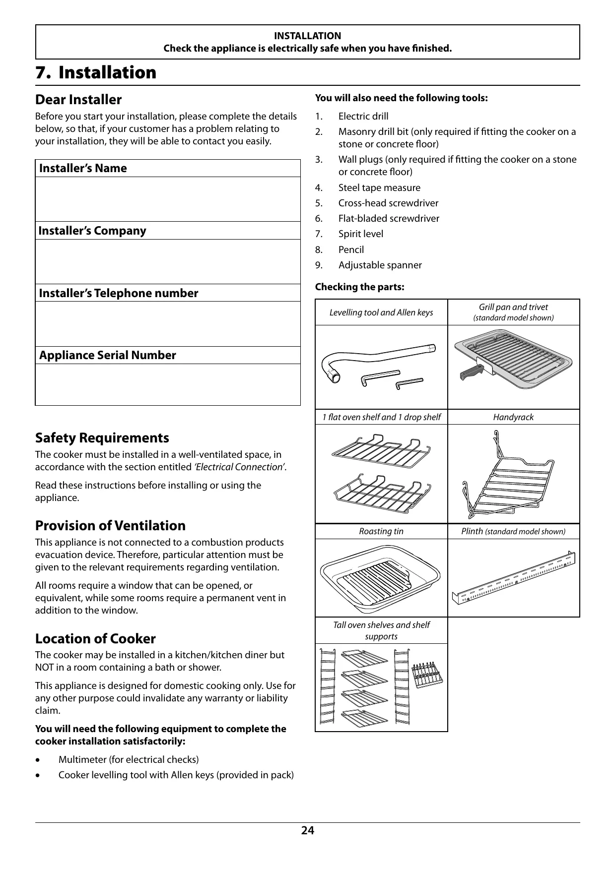
Checking the parts:
| Levelling tool and Allen keys | Grill pan and trivet (standard model shown) |
| 1 flat oven shelf and 1 drop shelf | Handyrack |
| Roasting tin | Plinth (standard model shown) |
| Tall oven shelves and shelf supports |
INSTALLATION
Check the appliance is electrically safe when you have finished.
Positioning the Cooker
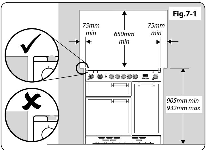
Fig.7-1 shows the minimum recommended distance from the cooker to nearby surfaces.
The cooker should not be placed on a base.
The hotplate surround should be level with, or above, any adjacent work surface. A gap of 75mm should be left between each side of the cooker ABOVE the hotplate level and any adjacent vertical surface.
For non-combustible surfaces (such as unpainted metal or ceramic tiles), this can be reduced to 25mm .
A minimum space of 650mm is required between the top of the hob and a horizontal combustible surface.
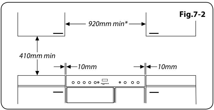
Fig.7-2 shows the suggested clearances above the cooker.
*Any cooker hood should be installed in accordance with the hood manufacturer's instructions.
Surfaces of furniture and walls at the sides and rear of the appliance should be heat, splash and steam resistant. Certain types of vinyl or laminate kitchen furniture are particularly prone to heat damage and discolouration. We cannot accept responsibility for damage caused by normal use of the cooker to any material that de-laminates or discolours at temperatures less than 65^ above room temperature.
We recommend a gap of 920mm between units to allow for moving the cooker. Do not box the cooker in – it must be possible to move the cooker in and out for cleaning and servicing.
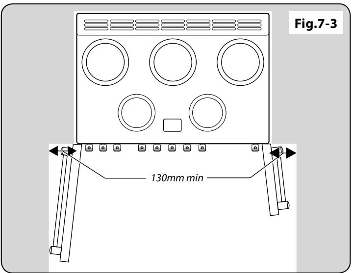
A clearance of 130mm is required if the cooker is near a corner of the kitchen, to allow the oven doors to open (Fig.7-3). The actual opening of the doors is slightly less, but this allows for some protection of your hand as you open the door.
Unpacking the Cooker
Do not take any packaging off the cooker until it is directly in front of the place in which it is to be installed (unless it will not fit through a door in its outer packaging).
Cut the banding straps and lift the cardboard box off the cooker, leaving the cooker standing on the base packaging. See the loose unpacking sheet.
Moving the Cooker

On no account try and move the cooker while it is plugged into the electricity supply.

The cooker is very heavy, so take great care.
We recommend two people manoeuvre the cooker. Ensure that the floor covering is firmly fixed, or removed to prevent it being disturbed when moving the cooker around. To help you, there are two levelling rollers at the back and two screw-down levelling feet at the front. You will need the levelling tool.
INSTALLATION
Check the appliance is electrically safe when you have finished.
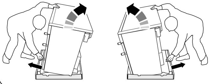
Fig.7-4
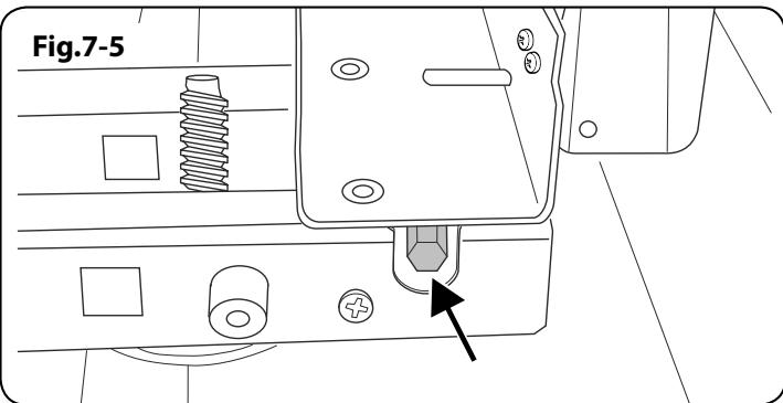
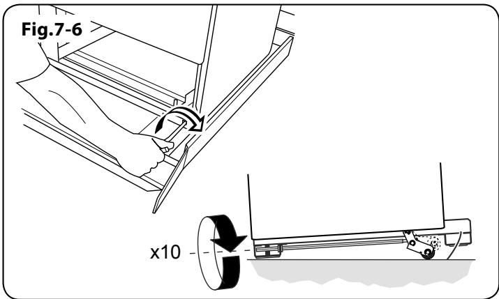
Fig.7-7
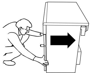
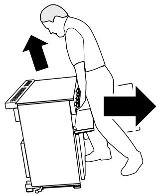
Fig.7-8
From the back, tilt the cooker forward and remove the rear half of the polystyrene base pack (Fig.7-4). Repeat from the front and remove the front half of the poly base.
Lower the Two Rear Rollers
First fit the levelling tool on the hexagonal adjusting nut (Fig.7-5).
Make 10 complete (360^) turns clockwise (Fig.7-6). (This means turning and removing the levelling tool 20 times.)
Make sure you lower BOTH REAR ROLLERS. There are two adjusting nuts, one for each roller, at both the front and bottom corners of the cooker.
Completing the Move
Unfold the rear edge of the pack base tray. Open the grill door and right-hand oven door so that you can get a good grip on the bottom of the fascia panel as you move the cooker.
Grip under the fascia panel and lift the front of the cooker slightly (Fig.7-7).
Carefully push the cooker backwards off the pack base. Remove the pack base tray. Position the cooker close to its final position, leaving just enough space to get behind it.
Do not use the door handles or control knobs to manoeuvre the cooker.
Repositioning the Cooker following Connection
If you need to move the cooker once it has been connected, make sure it is switched off at the supply switch before gripping under the fascia panel and lifting the front of the cooker slightly (Fig.7-8). Check behind the cooker to ensure that the electricity cable is not caught. As you progress, always ensure that the cable has sufficient slack to allow the cooker to move.
If a stability chain is fitted, release it as you ease the cooker out. Do not forget to refit it when you replace the cooker.
When you replace the cooker, check behind it again once more to ensure that the electricity cable is not caught or trapped.
Levelling
It is recommended that you use a spirit level on a shelf in one of the ovens to check for level.
Place the cooker in its intended position. Take care not to twist it within the gap between the kitchen units, as otherwise, damage may occur to the cooker or units.
The front feet and rear rollers can be adjusted to level the cooker. To adjust the height of the rear of the cooker, use the levelling tool supplied to turn the roller adjusting nuts at the front bottom corners of the cooker. To raise or lower the feet, simply turn the disks that are fitted onto them.
INSTALLATION
Check the appliance is electrically safe when you have finished.
Electrical Connection
The cooker must be installed by a qualified electrician, in accordance with all relevant British Standards/Codes of Practice (in particular BS 7671), or with the relevant national and local regulations.
Current Operated Earth Leakage Breakers
The combined use of your cooker and other domestic appliances may cause nuisance tripping, so we recommend that the cooker is protected on an individual RCD (Residual Current Device) or RCBO (Residual Current Breaker with Overload).
IF IN DOUBT, PLEASE CONSULT A SUITABLY QUALIFIED ELECTRICIAN.

WARNING: THE APPLIANCE MUST BE EARTHED.
Note: The cooker must be connected to the correct electrical supply as stated on the voltage label on the cooker, through a suitable cooker control unit incorporating a double pole switch, having a contact separation of at least 3mm in all poles.

The cooker MUST NOT be connected to an ordinary domestic power point.
Access to the mains terminal is gained by removing the electrical terminal cover box on the back panel. Connect the mains cable to the correct terminals for your electrical supply type (Fig.7-9 and Fig.7-10). Check that the links are correctly fitted and that the terminal screws are tight. Secure the mains cable using the cable clamp.
Hob Check
Check each cooking zone in turn. Be sure to use pans of the correct size and material.
Grill Check
Turn on the grill control and check that the grill heats up.
Oven Check
Set the clock as described earlier, and then turn on the ovens. Check the oven fans start to turn and that the ovens heat up.
Fitting the Handles and Handrail (depending on model)
Remove the 4mm Allen screws from the doors (Fig.7-11). Fit the door handles and secure using the 4mm screws.

The handles should be above the fixings.
Fit the plastic blanking plugs to the fixing holes (Fig.7-12).
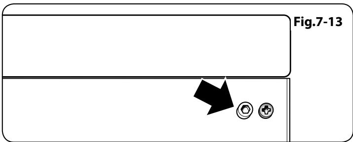
Remove the 4mm Allen screws from the top corners of the fascia (Fig.7-13). Fit the front handrail in position and secure using the 4mm screws.
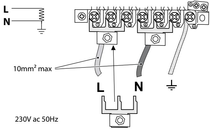
Fig.7-9
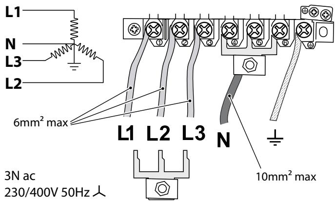
Fig.7-10
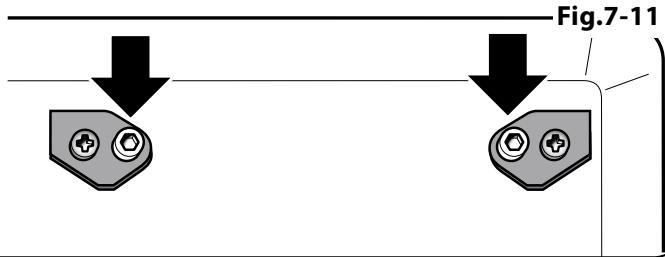
Fig.7-11
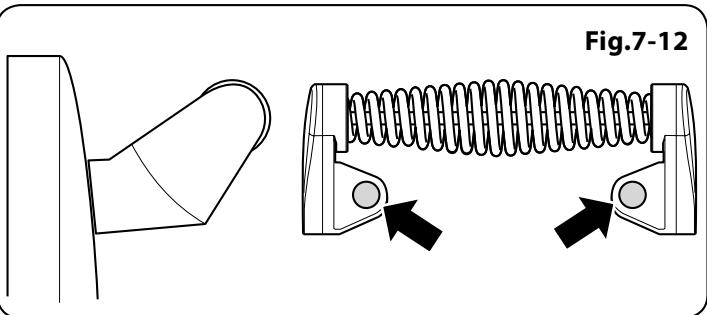
Fig.7-12
INSTALLATION
Check the appliance is electrically safe when you have finished.
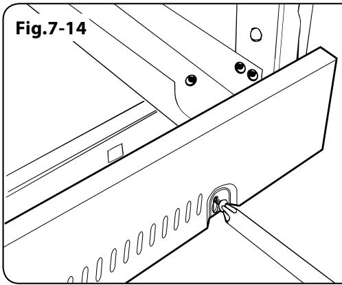
Fig.7-15
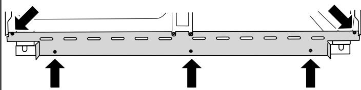
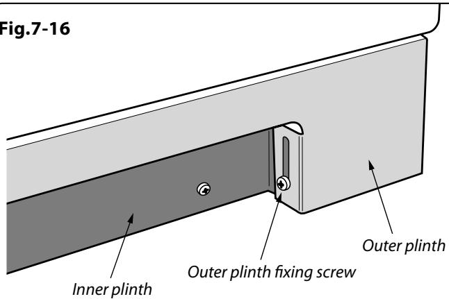
Fig.7-16
Splashback retaining clip
Fitting the Plinth
Loosen the three screws along the front bottom edge of the cooker. Hook the central keyhole over the central screw. Twist and fit each end keyhole over their respective screws. Tighten the fixing screws (Fig.7-14).
Fitting the Plinth (Kitchenener and Toledo only)
Fit the inner plinth to the bottom front of the cooker using the 5 screws provided (Fig.7-15).
Fit the outer plinth (2 screws, 1 each end) to the inner plinth. The height of the outer plinth can be adjusted by sliding it up or down via the slotted hole (Fig.7-16).
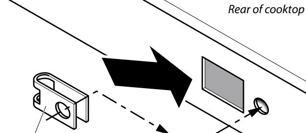
Fitting the Splashback (optional)
The splashback secures to the back of the hotplate using the securing clips and screws provided. Slide the clips into the openings on the rear of the hotplate, making sure to align the holes in the clips to the holes in the hotplate (Fig.7-17).
Position the splashback on the rear of the hotplate and secure with the screws supplied.
Customer Care
Installer: Please complete your details in this Guide, inform the user how to operate the cooker and hand oven the instructions.
Thank you.
Clarence Street, Royal Leamington Spa,
Warwickshire, CV31 2AD, England.
Tel: +44 (0) 1926 457400 Fax: +44 (0) 1926 450526
E-mail: consumers @rangemaster.co.uk