USER MANUAL RN-361DS DAEWOO
2-1.DISPLAY 9
2-2. Temperature Control of Refrigerator compartment 10
2-3.Defrost Mode 11
2-4. Function of Low Ambient Temperature 13
2-5. Prevention of Compressor Restart 13
2-6.BuzzerSound 13
2-7. Control of R Sensor OFF Point 14
2-8.Error Display 15
3. DISASSEMBLY
3-1. Door Switch 16
3-2. Cover Multi-Flow Duct As (in Fresh food Compartment) 17
3-3. Louver F As (in Frozen Food Compartment) 18
3-4. Door F/R 19
3-5.FRONT CONTL PANELPCB 21
4.How to Change Door Position 22
5.How to Charge R-600a Refrigerant 23
6. Part List
6-1. Cabinet Compartment 28
6-2. Compressor Room Compartment 29
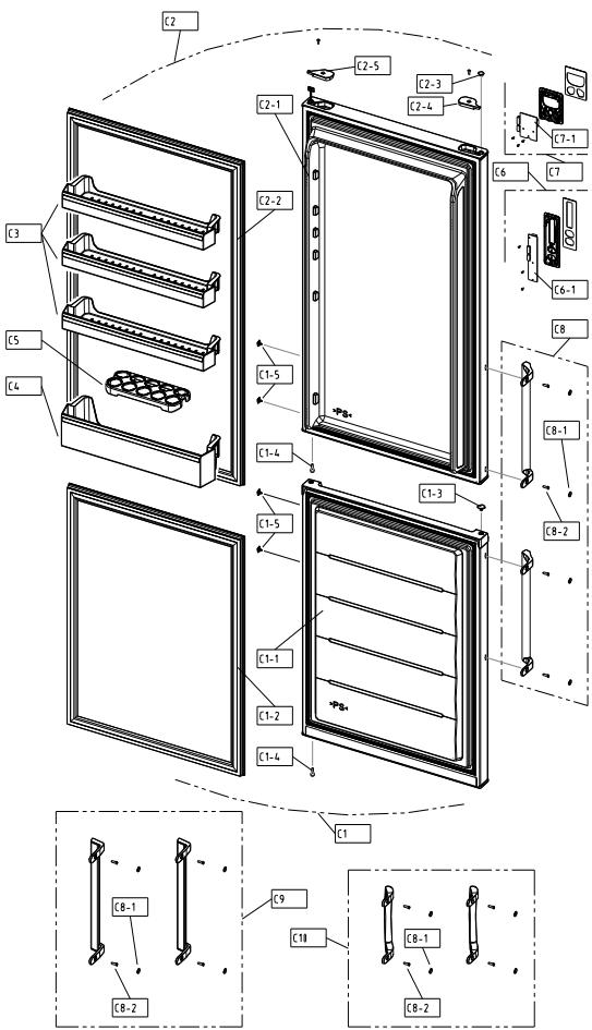
6-3. Door Compartment 30
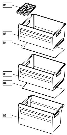
6-4. Frozen Food Compartment 33
6-5. Fresh Food Compartment 34
1-1. Model Information
* is the Door Type
| Buyer No. | RN-34*N | |
| Factory No. | RFP-31*N*P8N | |
| Control Type | Front Control Panel Button |
| Gross Vol.
IEC 62552
(unit: L) | Total | 337 |
| Freezer | 111 |
| Refrigerator | 226 |
| Storage Vol.
IEC 62552
(unit: L) | Total | 305 |
| Freezer | 84 |
| Refrigerator | 221 |
| Diemension
(unit: mm) | Net Width (Packing) | 595(634) |
| Net Depth (Packing) | 650(685) |
| Net Height (Packing) | 1870(1970) |
| Cooling Cycle | Refrigerant Type | R-600a |
| Refrigerant Charge | 0.044kg |
| Evaporator Type | Fin Type |
| Condenser Type | Natural Convection Cooling System |
| Dryer | Desiccant: Molecular Sieve xH-9 |
| Capillary Tube (unit: mm) | ID0.75 x T0.55 x L2290 |
| Heater | Defrost Type | Automatic Start & Stop |
| Defrost Heater | AC230V, 130W |
| Defrost Shape | Sheath Type |
| Electric Part | Freezer Fan Motor | AC 220V/50Hz, 2500RPM |
| Refrigerator Lighting | Bulb 15W x 1EA |
| Net Weight (Packing) | 67(73)kg |
| Blowing Agent | C-Pentane |
1-2. Interior Parts
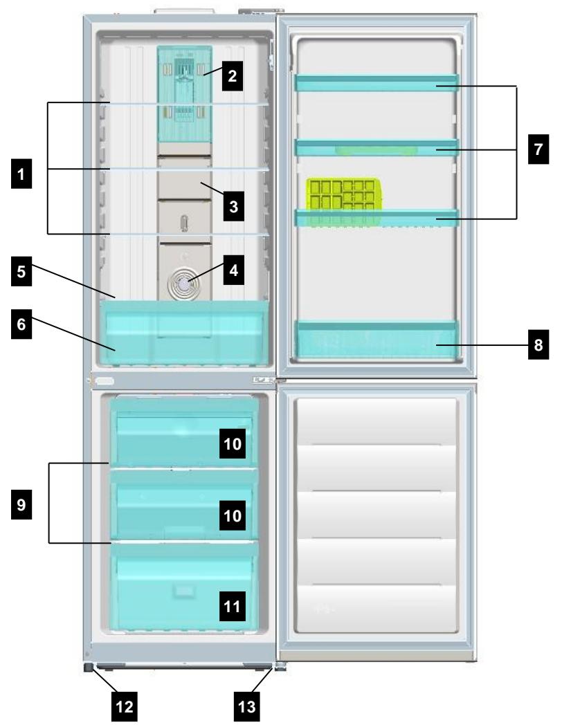
- Refrigerator Shelves
- Lamp Window
- Multi Duct
- Knob R Control
- Cover Vegetable Case
-
Vegetable Case
-
Refrigerator Pocket "R"
- Refrigerator Pocket "J"
- Freezer Shelves
- Freezer Case "A"
- Freezer Case "B"
- Adjusting Leg (Left)
- Adjusting Leg (Right)
1-3. Machine (Compressor) Compartment View
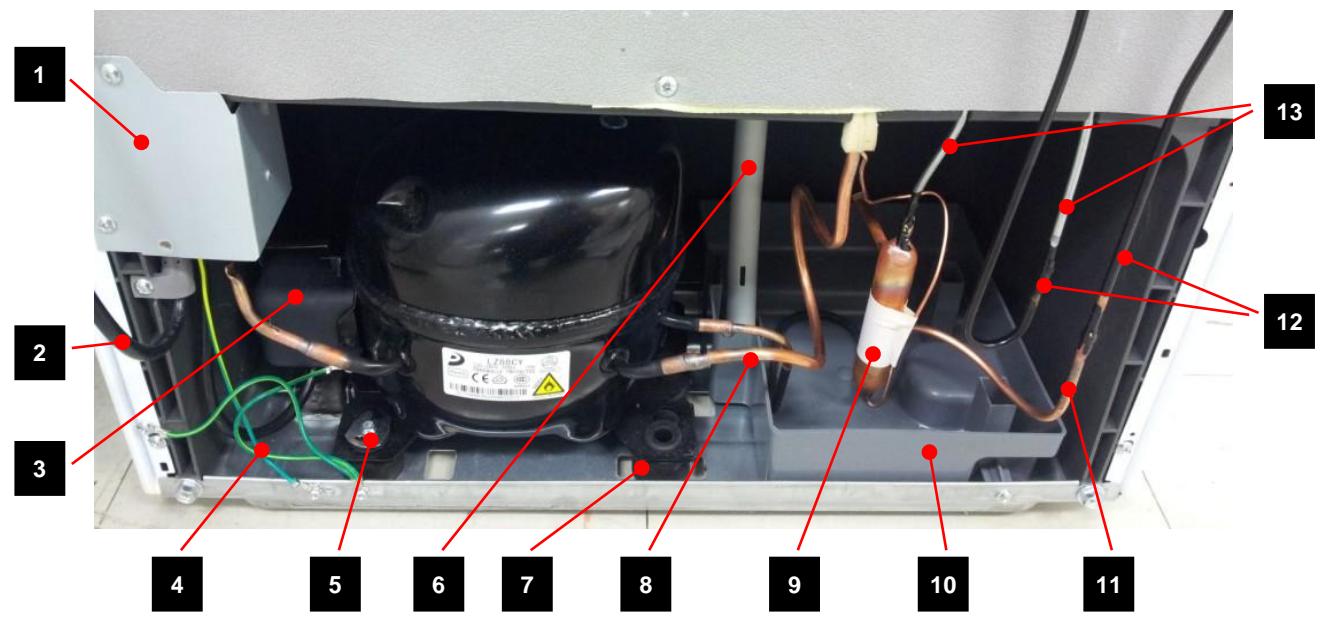
1.Box Power As (Capacitor Run)
2. Power Cord
3. Switch P Relay As
4. Earth Comp Wire
5. Fixture Compressor (Washer)
6. Drain Hose
7. Compressor Absorber
- Suction Pipe As
- Dryer As
- Case vaporization As
11.Pipe connector A
- Pipe Wire Condensor As
- Pipe Hot
1-4. Refrigerant Cycle
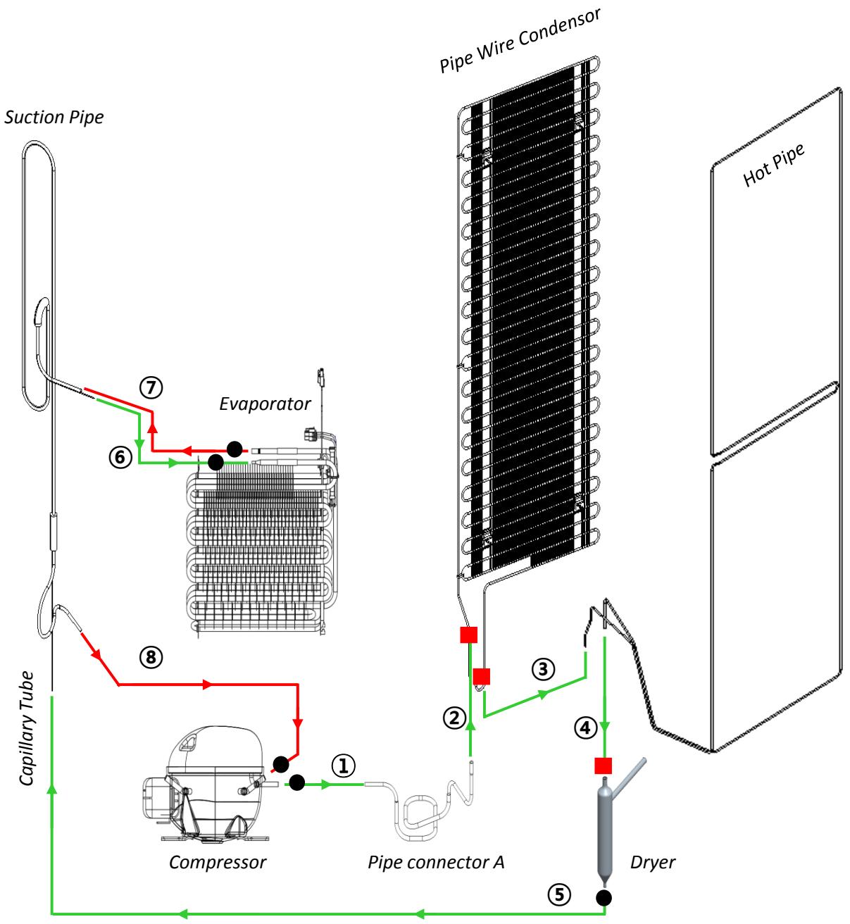
| ● | Copper Welding ( Ag 5%) | 5 Point |
| ■ | Silver Welding ( Ag 30%) | 3 Point |
1-5. Temperature Diagram
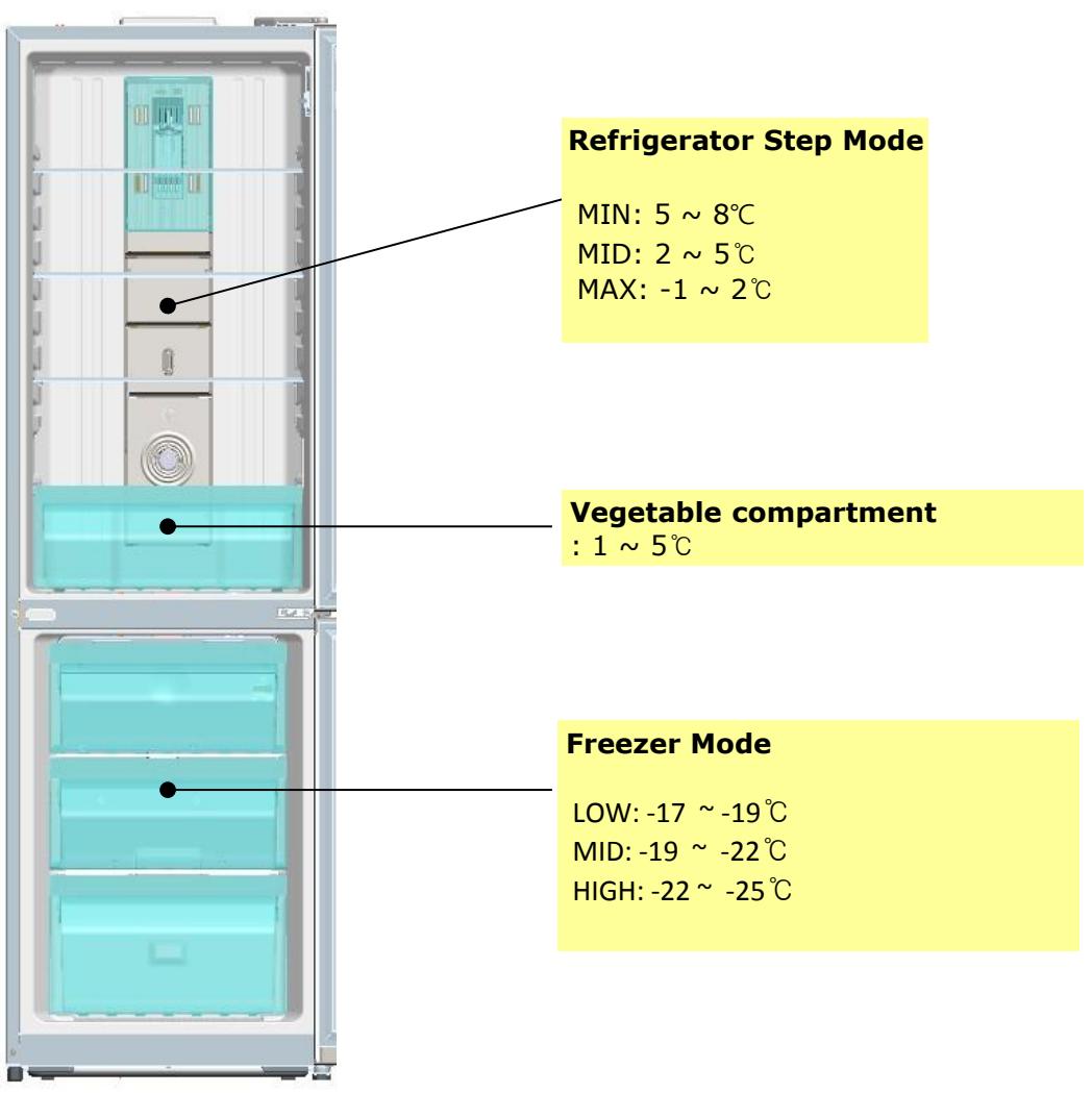

; The actual inner temperature varies depending on the food status, as the indicated setting temperature is a target temperature, not actual temperature within refrigerator.
; Refrigeration function is weak in the initial time.
Please adjust temperature as above after using refrigerator for minimum 1 ~ 2 days.
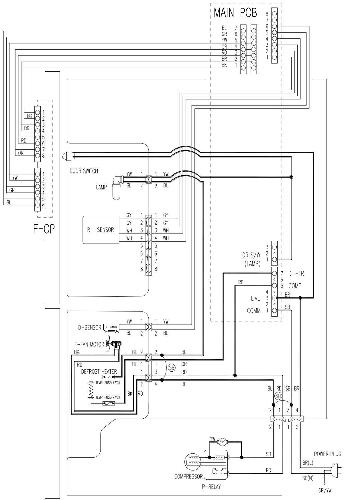
1-6. Wiring Diagram
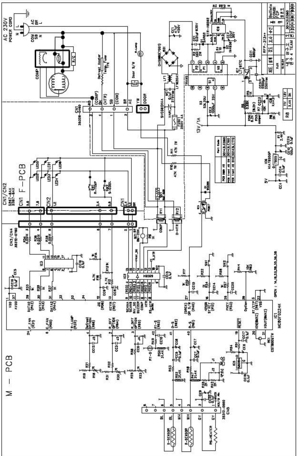
1.7. Main PCB Circuit Diagram
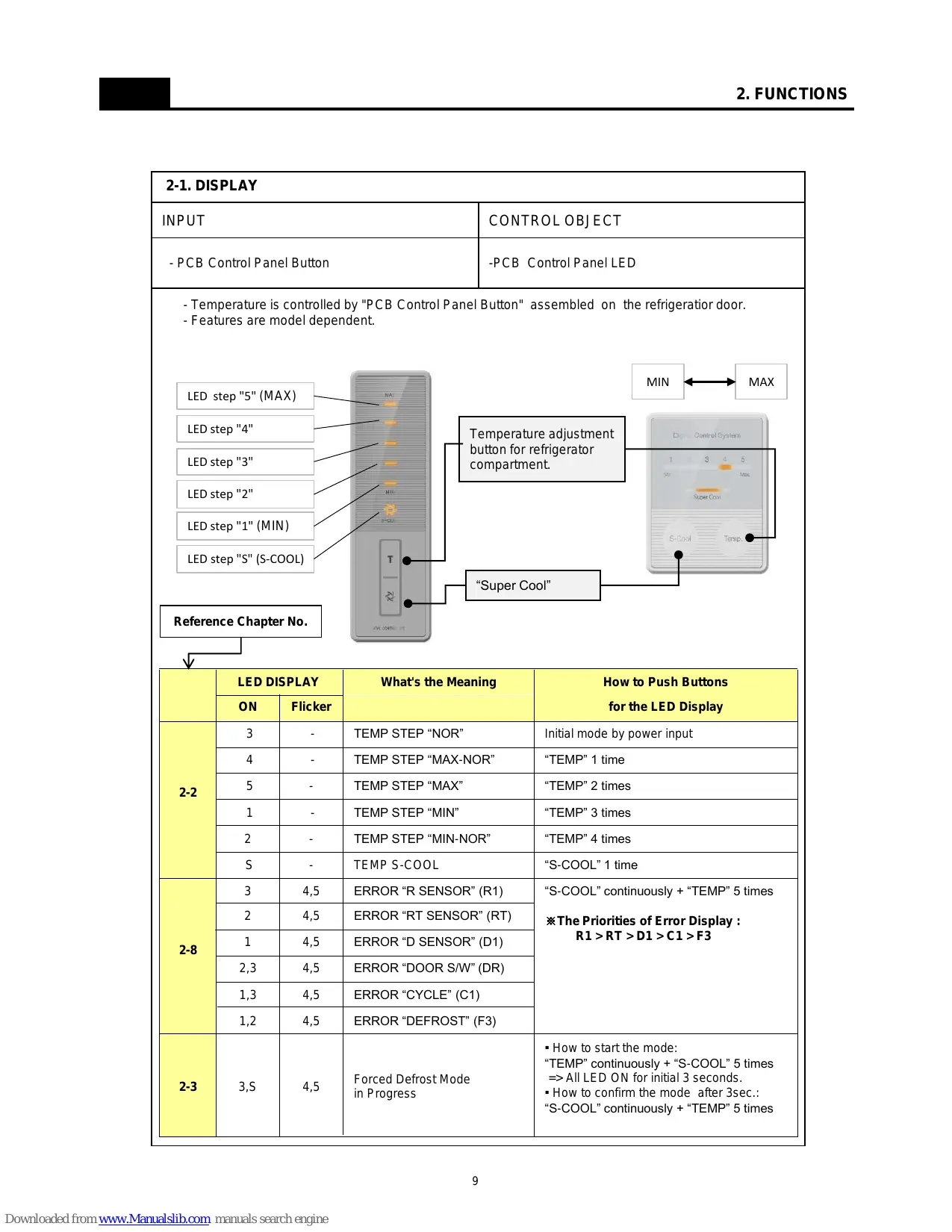
| 2-1. DISPLAY |
| INPUT | CONTROL OBJECT |
| - PCB Control Panel Button | -PCB Control Panel LED |
| - Temperature is controlled by "PCB Control Panel Button" assembled on the refrigerator door.
- Features are model dependent. |
| LED step "5" (MAX) | Temperature adjustment
button for refrigerator
compartment. | MIN MAX |
| LED step "4" |
| LED step "3" |
| LED step "2" |
| LED step "1" (MIN) |
| LED step "S" (S-COOL) |
| Reference Chapter No. | "Super Cool" |
| ↓ |
| LED DISPLAY | What's the Meaning | How to Push Buttons
for the LED Display |
| ON | Flicker |
| 2-2 | 3 | - | TEMP STEP "NOR" | Initial mode by power input |
| 4 | - | TEMP STEP "MAX-NOR" | "TEMP" 1 time |
| 5 | - | TEMP STEP "MAX" | "TEMP" 2 times |
| 1 | - | TEMP STEP "MIN" | "TEMP" 3 times |
| 2 | - | TEMP STEP "MIN-NOR" | "TEMP" 4 times |
| S | - | TEMP S-COOL | "S-COOL" 1 time |
| 2-8 | 3 | 4,5 | ERROR "R SENSOR" (R1) | "S-COOL" continuously + "TEMP" 5 times
*The Priorities of Error Display : R1 > RT > D1 > C1 > F3 |
| 2 | 4,5 | ERROR "RT SENSOR" (RT) |
| 1 | 4,5 | ERROR "D SENSOR" (D1) |
| 2,3 | 4,5 | ERROR "DOOR S/W" (DR) |
| 1,3 | 4,5 | ERROR "CYCLE" (C1) |
| 1,2 | 4,5 | ERROR "DEFROST" (F3) |
| 2-3 | 3,S | 4,5 | Forced Defrost Mode
in Progress | • How to start the mode:
"TEMP" continuously + "S-COOL" 5 times => All LED ON for initial 3 seconds.
• How to confirm the mode after 3sec.: "S-COOL" continuously + "TEMP" 5 times |
| 2-2. Temperature Control of Refrigerator Compartment |
| INPUT | CONTROL OBJECT |
| - PCB Control Panel "TEMP" and "S-Cool" Buttons
- R sensor | - COMPRESSOR
- FAN |
| A. "TEMP" Button of the Panel
- Temperature control of Refrigerator compartment
- 5 step mode of successive temperature mode
- Initial mode by power input: step 3 (NOR)
- Temperature will be set if the button doesn't get pressed again within 5 sec.
- Whenever pressing "TEMP" button, setting is repeated in the order of
"NOR" → "MAX-NOR" → "MAX" → "MIN" → "MIN-NOR" (LED DISPLAY ON) |
| B. Temperature of Refrigerator Control
- COMP and FAN will be controlled by the on/off condition of each mode
- Temperature Difference of Refrigerator each step : |
| STEP | 1 | 2 | 3 | 4 | 5 |
| ON(℃) | 9.4 | 7.1 | 4.9 | 3.4 | 1.2 |
| OFF(℃) | -0.5 | -1.6 | -3.7 | -5.2 | -7.2 |
| C. Temperature of Refrigerator at "NOR" OFF point:
-3.7℃ |
| D. S-Cool (Quick Refrigeration) Mode
- Press "S-Cool" Button of the Panel and make "S-Cool" LED on.
- Comp & Fan are on until R-sensor reaches to "Over Refrigeration OFF Point", -9.5℃
- After the reach of -9.5℃, Step 5(MAX) mode continues.
- When "S-Cool" mode lasts for about 40 minutes, it returns to general operation mode. |
| E. Temperature of Freezer Control
-It will be only controlled by using "KNOB F LOUVER" in the Freezer Comaprtment. |
| | | | | |
| 2-3. Defrost Mode |
| INPUT | CONTROL OBJECT |
| - Accumulated Compressor Run Time
- Running Time Ratio of Compressor
- Accumulated Door Open Time
- Ambient temperature (RT) | - Compressor
- F Fan
- Defrost Heater |
| A. Defrost Mode Operation conditon
(1) In case accumulated compressor run times: 6, 8, 10, 12 hours,
- when there occur any errors:
R1, D1, C1, RT, Door SW error etc. (Check "2-9. ERROR DISPLAY")
- or, running rate of COMP (per 2hrs of accumulated operation time) is more than 90%
- or, accumulated door open time is over 2 minutes
- or, ambient temperature (RT) is more than 38℃
(2) Even if the above condition is not satisfied,
defrost mode starts immediately when accumulated compressor run time is 14hrs. |
| B. Normal Defrost Mode |
| PRE-COOL
Defrost Heater on | ·Comp ON, Fan On, Heater OFF
·Comp runs for 25min. before defrost mode |
| ·Comp OFF, Fan OFF, Heater ON
·Heater off when 'D-Sensor' is over 10℃.
·Heater off after 60min. at normal control.
·Heater off after 40min. in case D1 error. |
| ·Comp OFF, Fan OFF, Heater OFF
·10minutes. |
| Pause | ·Normal Operation |
| C. Forced Defrost Mode
- How to start:
by press "TEMP" button for continuously and "S-COOL" button 5 times.
- If appliance has any error, Forces Defrost Mode don't start.
- Process: same as Normal Defrost Mode except 'PRE-COOL'
※ Heater is supposed to be on Initial 30sec. even though the temp. at "D SENSOR" is over 13℃. (for TEST)
- How to confirm:
1) buzzer sound 3times and all LED on for 3 sec., when Forced Defrost Mode start.
2) LED "3", "S-COOL" on and "4", "5" flickering by pushing "S-COOL" button for continuously and "TEMP" button 5 times after Forced Defrost Mode start. |
2-3. Defrost Mode
D. Flow chart of How to Start Defrost Mode
※ A.C.R.T.: Accumulated Compessor Run Times
※ R.R.O.C.: Running Rate of Compressor
※ RT: Ambient temperature
※ T.C.O.T.: Total Compressor ON/OFF Times

| 2-4. Function of Low Ambient Temperature (RT) |
| INPUT | CONTROL OBJECT |
| RT | - R HTR
- COMP |
| A. Condition of LOW RT
- RT sensor below 19℃
- When the RT sensor is over 20℃, the system comes to be “General Operation Mode”.
- When the RT sensor is between 19℃ to 20℃, the system keeps the previous mode.
B. Control
- When the temp of RT sensor is between 14℃ to 19℃, COMP on/off temp is 3℃ UP
- When the temp of RT sensor is below 14℃, COMP ON/OFF temp is 4℃ UP |
|
| 2-5. Prevention of Compressor Restart |
| INPUT | CONTROL OBJECT |
| N/A | COMP |
| It takes several minutes to protect Compressor:
(1) 6 minutes after Comp off
(2) 30 minutes at operation of Low RT, but 6 minutes when the doors open more than 20 seconds |
|
| 2-6. Buzzer Sound |
| INPUT | CONTROL OBJECT |
| - Forced Defrost Mode start
- Door Switch
- Initial Power Input | Buzzer |
| A. When Forced Defrost Mode start, the buzzer rings 3times.
B. After 2 minutes power's on, the buzzer rings 3 times.
C. At Short Circuit Test, the buzzer rings 1 times.
D. When door opens, the buzzer rings every 1 minute for 5 minutes. |
| 2-7. Control of R-sensor OFF Point |
| INPUT | CONTROL OBJECT |
| "J1", "J2" On Main PCB | Control Resistance of R sensor OFF Point |
| - When the refrigeration of refrigerator is poor or weak though Fan and COMP are working continuously, the following actions are recommended for service.
(1) Resistance (R25): Default resistance (31.4Kohms)
(2) Resistance (R26): Cut the "J1" off to reduce basic resistance by 1.5°C. (2Kohms up)
(3) Resistance (R27): Cut the "J2" off additionally to reduce basic resistance by 1.5°C. (total 4Kohms up)
※ R25 = R-SENSOR OFF point
R25 + R26 = R-SENSOR OFF point - 1.5°C
R25 + R26 + R27 = R-SENSOR OFF point - 3°C |
| 2-8. Error Display |
| INPUT | CONTROL OBJECT |
| PCB Control Panel Buttons on Door | LED DISPLAY |
| - Error Check Mode
(1) How to start: Push "S-COOL" button for continuously and "TEMP" button 5 times.
(2) What happen: LED "4 & 5" flickering, and if any errors occur, the related LEDs on.
(3) CANCEL: Push "TEMP" button 1 time, or wait 4 minutes.
※ After operations back to normal, the displays come to be reset. |
| A. "R1" ERROR
: It happens when R-Sensor is OPEN or SHORT.
(1) LED DISPLAY: LED "3" on, "4 & 5" flickering
(2) REACTION: Controlled by the following condition of RT |
| RT sensor TEMP (unit:°C) | ~13 | ~19 | ~29 | 29~ |
| COMP. Operating ON/OFF TIME (unit:min.) | 6/34 | 10/30 | 16/24 | 20/20 |
| ※ If "RT" ERROR happens at the same time, COMP. Operating ON/OFF Time is 16min/24min.
(3) RELEASE: When R-Sensor is working normally. |
| B. "RT" ERROR
: It happens when RT-Sensor is OPEN or SHORT.
(1) LED DISPLAY: LED "2" on, "4 & 5" flickering
(2) REACTION: Delete the conditions of RT-sensor Control and operate normally.
(3) RELEASE: When RT-Sensor is working normally. |
| C. "d1" ERROR
: It happens when D-Sensor is OPEN or SHORT.
(1) LED DISPLAY: LED "1" on, "4 & 5" flickering
(2) REACTION: Return to next limit Defrost Time (40 min)
(3) RELEASE: When D-Sensor is working normally. |
| D. "DR" ERROR
: It happens when the system senses door opens more than 1 hour.
(1) LED DISPLAY: LED "2 & 3" on, "4 & 5" flickering
(2) REACTION: Delete function relating to door switch sensing
(3) RELEASE: When sensing close from door S/W. |
3-1. Door Switch
| No | Procedure | No | Procedure |
| 1 | Inuput a thin driver in the upper part as above picture.
And lift up 'Door Switch' carefully. | 3 | |
| 2 | Inuput a thin driver in the lower part as above picture.
And lift up 'Door Switch' carefully. | Disconnect the wire housing. |
3-2. Cover Multi-Flow Duct As (in Fresh food Compartment)
| No | Procedure | No | Procedure |
| 1 | Unlock the lamp window
(1) Push the window right side
(2) Lever two window lock with flat driver | 4 | the Mark of Locking Position
Push
Unlock the 'COVER M/FLOW DUCT'
(1) Check the marks of locking position on 'Cover'.
(Number of the marks are model dependent)
(2) Push the 'cover' inside and Unlock. |
| 2 | 'A' axis
Open window turning on the axis 'A' | 5 | |
| 3 | screw cap
Remove two screw cap with flat driver.
Unscrew 2 points | unscrew
Unscrew | Disconnect the Lamp & Sensor wire housing. |
3-3. Louver F As (in Frozen Food Compartment)
| No | Procedure | No | Procedure |
| 1 | Unscrew to disassemble the 'Louver F As' from Freezer. | 4 | Unscrew to disassemble as each component part. |
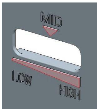
| 2 | Remove the 'Louver F As' pulling the top side. | 5 | Unlock carefully. (especially, inside 3 locks) |
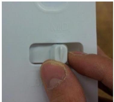
| 3 | Disconnect Fan motor wire housing. | inside 3
*KNOB F'
*Default position of 'KNOB F' is 'MID' |
3-4. DOOR F/R
| No | Procedure | No | Procedure |
| 1 | Tilt down the appliance to the rear. | 4 | Remove door in fresh food compartment.
And unscrew middle hinge. |
| 2 | Unscrew and lift up top cover hinge to remove. | 5 | washer
※ Don't forget the washer for middle hinge. |
| 3 | Unscrew and remove top hinge. | 5 | Lift up middle cover hinge to remove. |
3-4. DOOR F/R
| No | Procedure | No | Procedure |
| 6 | Unscrew and remove under hinge.
washer
※ Don't forget the washer for under hinge.
※ The washer for under hinge's bigger than middle one. | 7 | Turn the 'Adjusting Leg (Left)' CCW and Remove. |
| 8 | Remove door in frozen food compart ment. |
3-5. Front Control Panel PCB
| No | Procedure | No | Procedure |
| 1 | MAX
Inuput a cutter sleeve between Panel and Door.
Be careful not to scratch the Door surface. | 2 | Lift up the Panel and disconnect the wire housing. |
| 3 | PCB
Panel
Unscrew and separate the panel and PCB. | |
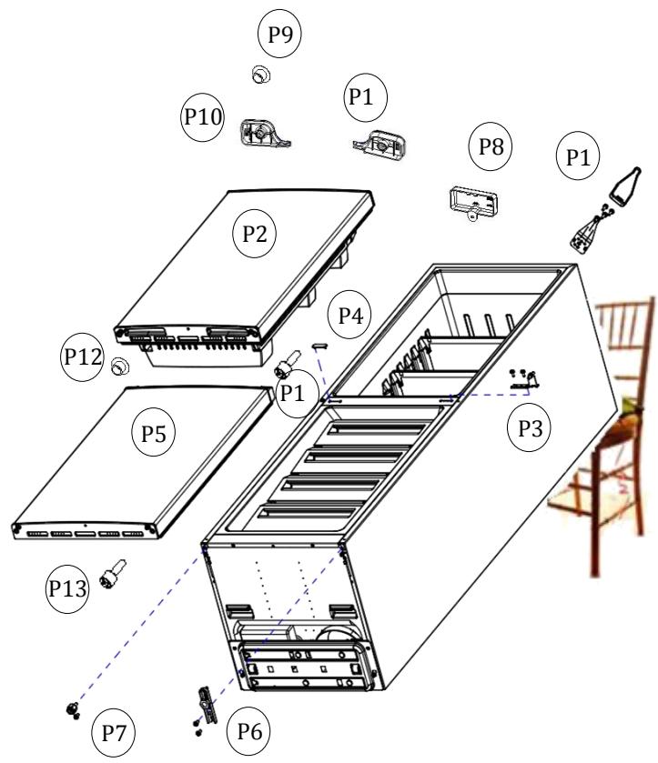
1-1> Tilt down the appliance to the rear. (Watch out for damage of Pipe Wire Condenser assembled in the rear of refrigerator.)
1-2> Disassemble following parts in order.
P1) 'Top Cover Hinge' and 'Top Hinge'
P2) 'Refrigerator Door'
P3) 'Middle Hinge'
P4) 'Middle Cover Hinge'
P5) 'Freezer Door'
P6) 'Under Hinge'
P7)'Adjusting Leg'
P8) 'Cover Cabinet Harness'
P9) 'Cap Refrigerator Door'
P10) 'Cover Door Harness Left'
P11) 'Cover Door Harness Right'
P12) 'Cap Freezer Door'
P13) 'Stopper Refrigerator/Freeze Door'
1-3> Move following parts in the opposite position: P9, P12, P13
1-4> Change the position of following parts each other and assemble them:
P6 & P7, P3 & P4, P1 & P8
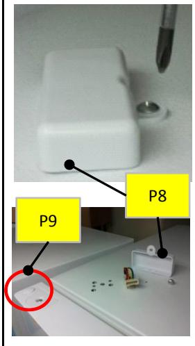
Disassemble "P8"
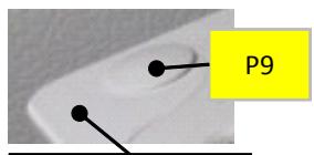
Disassemble "P9"
Refrigerator Door
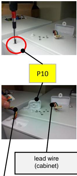
Disassemble "P10"
lead wire (door)
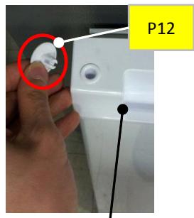
Disassemble "P12"
Freezer Door
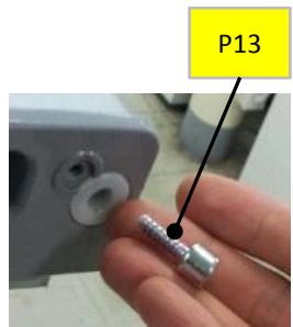
Disassemble "P13"
1-5> Assemble following parts:
P5, P2, P10, P11
5-1. Safety Warning ( R-600a Refrigerant Models Only)
R600a
This appliance contains a certain amount of isobutane refrigerant (R600a) a natural gas with high environmental compatibility that is, however, also combustible.
When transporting and installing the appliance, care should be taken to ensure that no parts of the refrigerating circuit are damaged.
Refrigerant squirting out of the pipes could ignite or cause an eye injury. If a leak is detected, avoid any naked flames or potential sources of ignition and air the room in which appliance is standing for several minutes.
- In order to avoid the creation of a flammable gas-air mixture if a leak in the refrigerating circuit occurs, the size of the room in which the appliance may be sited depends on the amount of refrigerant used. The room must be 1m3 in size for every 8g of R600a refrigerant inside the appliance. The amount of refrigerant is shown on the identification plate inside the appliance.
- Never start up an appliance showing any songs of damage. If in doubt, consult your dealer.
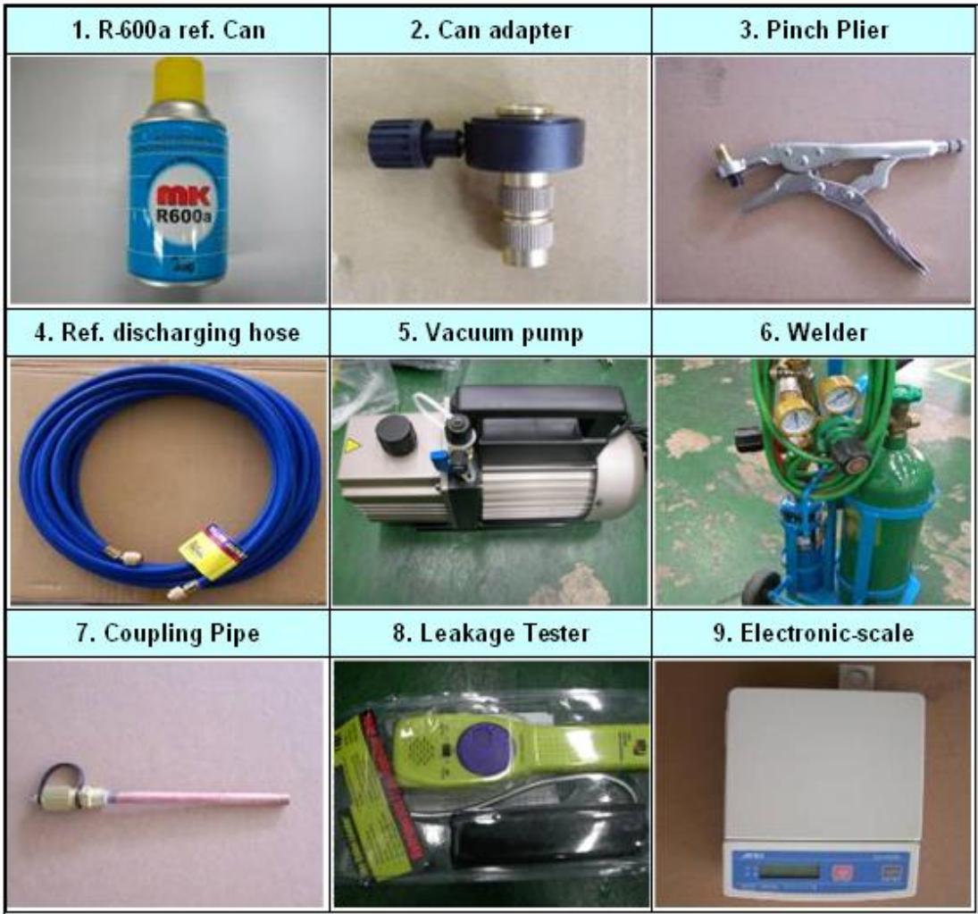
5-3. Process Summary
1st Step. R-600a ref. discharging
- Connect the discharging hose to the outdoors.
- Time: 7 min.
2nd Step. Removing the remaining refrigerant
- For removing of remaning refrigerant., connect the discharging hose to the vacuum pump
-Time:10min
3th Step. Exchanging comp. & dryer / pipe welding
- Exchange Comp. and Dryer
- Welding the Pipe
- Copper-Copper : 5% rod
- Copper-Steel : 30% rod
4th Step. Welding coupling pipe
Coupling cap and gas charging cap should be seperated before welding.
5th Step. Vacuum
- Check the vacuum with (mani-polder) gauge
- Time : 60~80min
6th Step. Charge R-600a
- Charging the ref. on POWER ON
- Time : 10min
5-4. In Detail Precess
| NO. | SVC process | Image | Details |
| 1 | Connecting the pinch-plier & discharging hose | OUT DOOR | 1. Connect the discharging hose to the pinch-plier
2. The outlet of discharging hose should be placed to the outdoorwindow) |
| 2 | Fixing the pinch-plier & charging pipe | | 1. Fix the pinch-plier to the compressor charging pipe.
2. Pinch-plier should not be moving freely.
※ If that is moving freely, it would cause fire/explosion as leakage gas in the room. |
| 3 | Discharging the R-600a ref. | | 1. Discharge the R-600a ref. to outdoor.
[Befor connecting the vacuum pump]
※ It should have enough time more than 7 minutes to discharge. |
| 4 | Removing the remaining ref. | | 1. And then, connect the vacuum pump to the outlet of discharging hose
※Vacum pump should be placed at the outdoor where is able to clear air easily.
※It should have enough time more than 10 minutes to discharge. |
| 5 | Removing the pinch-plier & pipe | ○ | 1. Disassemble the each pipe (Del-pipe, Suc-pipe, Capi-pipe, Dryer & Hot-pipe)
※Caution; A part is easily damaged by flame so that disassembly should be done carefully. |
| 6 | Exchanging comp & dryer | ○ | 1. Change the comp. & dryer.
※You should check the comp. spec. and assemble correctly. |
| 7 | Welding | | 1. Weld the each pipe.
※O Copper-Copper welding - 5% rod
△ Copper-Steel welding - 35% rod |
| 8 | Disassembly of charging valve (Coupling pipe) | Valve Ass'y
Valve Ass'y | 1. Decap the coupling pipe cap and disassemble the vlave ass'y.
※If you don't disassemble, the coupling rubber would be melted. |
| 9 | Coupling pipe welding | | 1. Weld after inserting the coupling pipe to the compressor.
※ Use the wet cloth for preventing the other part of machinery-room from damage. |
| 10 | Valve reass'y & guage connecting | | 1. Reassemble the valve ass'y with coupling pipe to clockwise.
2. Connect the blue hose of the guage to the coupling pipe and the yellow hose to the vacuum pump.
3. Open the blue guage lever and start the vacuum pump |
| |
| 11 | Vacuum | | 1. Be vacuumed the cycle with pump.
※ Time: 60~80min
=> If the vacuum time is less than 60min, ref. COP & air coolong would be weak. |
| 12 | Check | | 1. Check the guage: -76cmHg
※ If the cycle is not vacuumed, it would be leak. |
| 13 | Adjusting the amounts of refrigerants (R-600a can) | | 1. Check the amounts of R-600a can with scale and discharge the surplus ref.
※ Discharging is surely done at the outdoor where is able to clear air.
※ Tip of adjusting.
- Can total weight:160g(Can 75g+Ref. 85g)
- Adapter:145g
=> Total:305g
- The amounts of charging:79g
=> Discharging:6g => Total:299g |
| 14 | Connecting of coupling pipe & adapta | | 1. Conect can adapter to the coupling pipe.
2. Charge the ref. with open lever slowly.
※ Refrigerant should never leak in the room. |
| 15 | Charging | | 1. On the power of refrigerator and then start to charge the ref. (10min)
※ Charge the ref. until going out the water vapour condensing on the can outlet. |
| 16 | Leakage Test | | 1. Check the leakage.
※ You must rework from Step.1 when the leakage is detected. |
| 17 | Finish | | 1. Clean and clear around the machinery room when the service is finished.
2. Assemble the machinery room cover. |
6.PART LIST
6-1. Cabinet Compartment
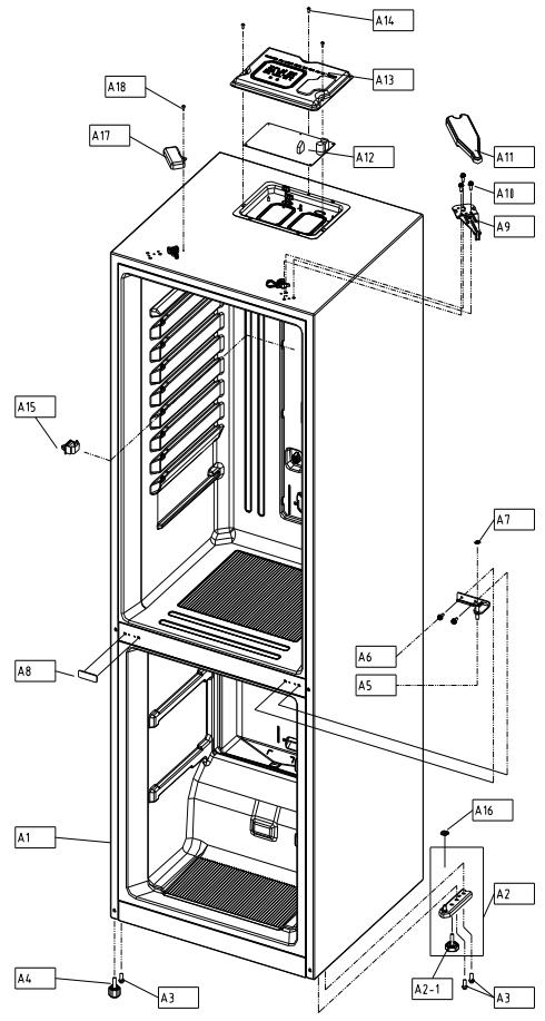
| NO | PART-CODE | PART NAME | SPEC. | Q'ty |
| RN-34* | |
| A1 | - | ASSY CAB URT AS | | 1 | |
| A2 | 3012938100 | HINGE *U AS | RFP-301 | 1 | |
| A2-1 | 3012105300 | FOOT ADJ AS | PP+INSERT | 1 | |
| A3 | 30160A1700 | SPECIAL BOLT | SWCH10A M8*L18 | 3 | |
| A4 | 3012106500 | FOOT ADJ *L AS | PP+INSERT | 1 | |
| A5 | 3012938000 | HINGE *M AS | RFP-301 | 1 | |
| A6 | 3016001250 | SPECIAL BOLT *M | 6X15 SWCH22A(WH) | 2 | |
| A7 | 3016044410 | SPECIAL WASHER *M HI | SGCC, T1.0XI.D9.0XO.D15 | 1 | |
| A8 | 3010937720 | CAP DV HI HOLE *M | HIPS | 1 | |
| A9 | 3012938900 | HINGE *T AS | RFP-311 | 1 | |
| A10 | 3016001250 | SPECIAL BOLT *M | 6X15 SWCH22A(WH) | 3 | |
| A11 | 301149DX00301149DX10301149DX20 | COVER HI *T | PP(White), RFP-311PP(T/SILVER), RFP-311PP(BLACK), RFP-311 | | |
| A12 | 30143LE060 | PCB MAIN AS | RFP-311 | 1 | |
| A13 | 3001416640 | COVER M/PCB BOX AS | PCM (BACK COATING) | 1 | |
| A14 | 7112401211 | SCREW TAPPING | T1 TRS 4*12 MFZN | 3 | |
| A15 | 301179DP00 | DOOR S/W AS | HC-050K4 250V2.5A | 1 | |
| A16 | 3816000200 | SPECIAL WASHER | SPCC T1.0 O.D21*1D8 MFZN | 1 | |
| A17 | 300141220030014122203001412230 | COVER CAB HRNS | PP(White), RFP-340PP(T/SILVER), RFP-340PP(BLACK), RFP-340 | | |
| A18 | 7112401211 | SCREW TAPPING | T1 TRS 4*12 MFZN | 1 | |
| | | | | |
| | | | | |
| | | | | |
| | | | | |
| | | | | |
- Please check the color, some parts code color dependent.
6.PART LIST
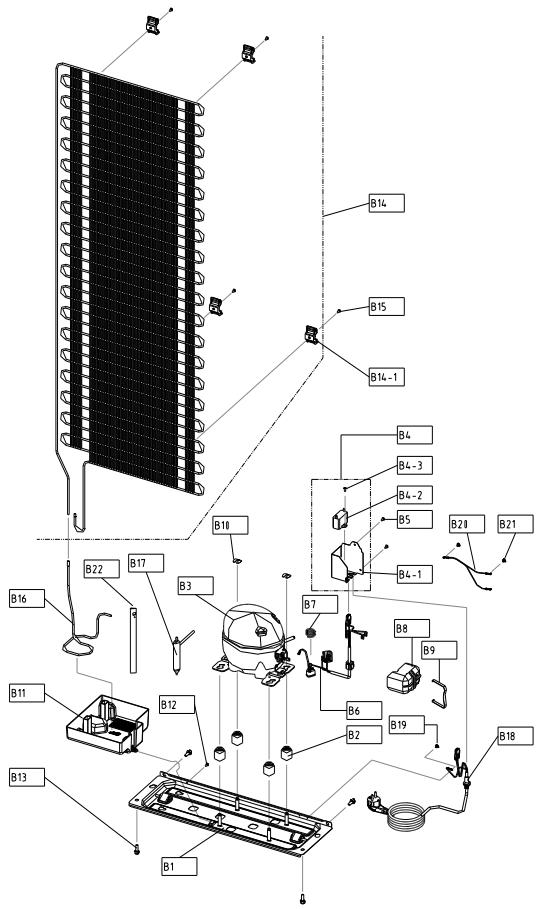
6-2. Compressor Room Compartment
| NO | PART-CODE | PART NAME | SPEC. | Q'ty |
| RN-34* | |
| B1 | 3010365500 | BASE COMP AS | RFP-301 | 1 | |
| B2 | 3010103400 | ABSORBER COMP | RUBBER | 4 | |
| B3 | 3956188C50 | COMPRESSOR | LZ88CY(QLZ12Y) 220-240V 50HZ | 1 | |
| B4 | 3010583700 | BOX POWER AS | RFP-301(400V/4UF) | 1 | |
| B4-1 | 3010552101 | BOX POWER | GI/T0.5 | 1 | |
| B4-2 | 3016406010 | CAPACITOR RUN | DMF-40405(400V 4UF) | 1 | |
| B4-3 | 7122401011 | SCREW TAPPING | T2S TRS 4*10 MFZN | 1 | |
| B5 | 7112401211 | SCREW TAPPING | T1 TRS 4*12 MFZN | 2 | |
| B6 | 3018134600 | SWITCH P RELAY AS | B60-120, OP2-15C(RSCR DONPER) | 1 | |
| B7 | 3015103900 | SPRING OVERLOAD PROTECTOR | LZ88CY OLP FIXING | 1 | |
| B8 | 3811402600 | COVER RELAY | LZ88CY | 1 | |
| B9 | 3015103800 | SPRING COVER RELAY | LZ88CY COVER RELAY FIXING | 1 | |
| B10 | 4019H09031 | SPECIAL WASHER | SWRH | 2 | |
| B11 | 301119VJ00 | CASE VAPORI AS | RFP-301 | 1 | |
| B12 | 7112401211 | SCREW TAPPING | T1 TRS 4*12 MFZN | 1 | |
| B13 | 3016003300 | SPECIAL BOLT | T2 M6.5*20 | 4 | |
| B14 | 3014480010 | PIPE WI-ICON AS | RFP-301 | 1 | |
| B14-1 | 3012041500 | FIXTURE W-ICON | HIPS | 4 | |
| B15 | 7112402011 | SCREW TAPPING | T1 TRS 4X20 MFZN | 4 | |
| B16 | 3014479420 | PIPE CONN A | DUCT1-0 OD4.76*T0.5 | 1 | |
| B17 | 3016808203 | DRYER AS | 10G, SINGLE TUBE | 1 | |
| B18 | 3011348111 | CORD POWER AS | FR-290(EUI), 250V 10/16A | 1 | |
| B19 | 7071400811 | SCREW MACHINE | PAN 4X8 SW MFZN+STAR WASHER | 1 | |
| B20 | 3012763210 | HARNESS EARTH COMP | FRM-241, L140 | 1 | |
| B21 | 7071400811 | SCREW MACHINE | PAN 4X8 SW MFZN+STAR WASHER | 2 | |
| B22 | 3012513950 | HOSE DRN B | PVC | 1 | |
| | | | | |
| | | | | |
| | | | | |
| | | | | |
| | | | | |
| | | | | |
| | | | | |
| | | | | |
| | | | | |
| | | | | |
| | | | | |
| | | | | |
| | | | | |
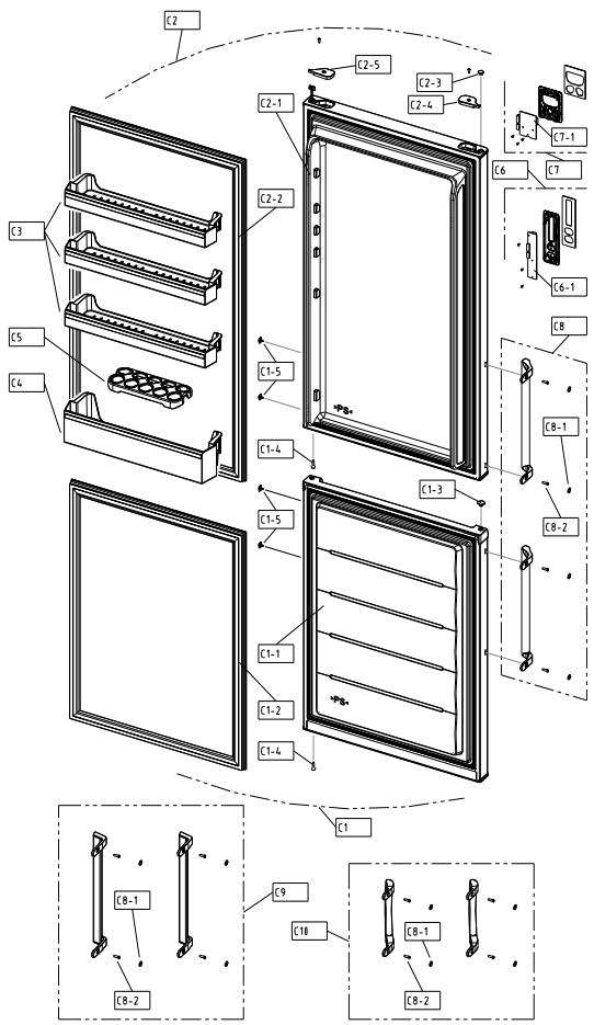
| NO | PART-CODE | PART NAME | SPEC. | Q'ty |
| COLOR | COLOR# | the others | RN-341 | RN-342 | RN-343 | RN-334 | RN-335 | RN-336 | |
| C1 | 30100B9X00 | ASSY F DR | WHITE | DWG1C | RFP-301 | 1 | x | x | x | x | x | |
| 30100B9X30 | AL SILVER | ASG4P | RFP-301 |
| 30100B9X40 | T/SILVER | TSH1P | RFP-301 |
| 30100B9X50 | BLACK | BLH1C | RFP-301 |
| | | |
| | | |
| 30100B9X20 | ASSY F DR | WHITE | DWG1C | RFP-302/303 | x | 1 | 1 | x | x | x | |
| 30100B9Y80 | AL SILVER | ASG4P | RFP-302/303 |
| 30100B9Y90 | T/SILVER | TSH1P | RFP-302/303 |
| 30100B9YA0 | BLACK | BLH1C | RFP-302/303 |
| | | |
| | | |
| 30100B9X10 | ASSY F DR | WHITE | DWG1C | RFP-304 | x | x | x | 1 | x | x | |
| 30100B9X70 | AL SILVER | ASG4P | RFP-304 |
| 30100B9X80 | T/SILVER | TSH1P | RFP-304 |
| 30100B9X90 | BLACK | BLH1C | RFP-304 |
| | | |
| | | |
| 30000CPN00 | ASSY F DR | WHITE | DWG1C | RFP-305 | x | x | x | x | 1 | x | |
| 30000CPN10 | AL SILVER | ASG4P | RFP-305 |
| 30000CPN20 | T/SILVER | TSH1P | RFP-305 |
| 30000CPN30 | BLACK | BLH1C | RFP-305 |
| | | |
| | | |
| 30000CPQ00 | ASSY F DR | WHITE | DWG1C | RFP-306 | x | x | x | x | x | 1 | |
| 30000CPQ10 | AL SILVER | ASG4P | RFP-306 |
| 30000CPQ20 | T/SILVER | TSH1P | RFP-306 |
| 30000CPQ30 | BLACK | BLH1C | RFP-306 |
| | | |
| | | |
| C1-1 | - | ASSY F DR URT | | | | 1 | 1 | 1 | 1 | 1 | 1 | |
| C1-2 | 3012330900 | GASKET F DR AS | GRAY | | | 1 | 1 | 1 | 1 | 1 | 1 | |
| 3012330910 | BLACK | | |
| C1-3 | 3011450300 | COVER CAP HOLE A | WHITE | | ABS, RFP-340 | 1 | 1 | 1 | 1 | 1 | 1 | |
| 3011450310 | SILVER | | ABS, RFP-340 |
| 3011450340 | BLACK | | ABS, RFP-340 |
| | | |
| | | |
| C1-4 | 3016047410 | SPECIAL STOPPER DR BOL | | | TAP-TITE 5'16 | 2 | 2 | 2 | 2 | 2 | 2 | |
| C1-5 | 3010985100 | CAP DR | WHITE | | ABS, RFP-340 | x | 4 | 4 | 4 | x | x | |
| 3010985110 | SILVER | | ABS, RFP-340 |
| 3010985120 | BLACK | | ABS, RFP-340 |
| | | |
| | | |
- Please check the color, some parts code color dependent.

| NO | PART-CODE | PART NAME | SPEC. | Q'ty |
| RN-341 | RN-342 | RN-343 | RN-334 | RN-335 | RN-336 | |
| C2 | 30100C4600 | ASSY R DR | WHITE | DWG1C | RFP-311 | 1 | x | x | x | x | x | |
| 30100C4610 | AL SILVER | ASG4P | RFP-311 |
| 30100C4620 | T/SILVER | TSH1P | RFP-311 |
| 30100C4630 | BLACK | BLH1C | RFP-311 |
| | | |
| | | |
| 30100C3G00 | ASSY R DR | WHITE | DWG1C | RFP-312/313 | x | 1 | 1 | x | x | x | |
| 30100C3G10 | AL SILVER | ASG4P | RFP-312/313 |
| 30100C4620 | T/SILVER | TSH1P | RFP-312/313 |
| 30100C3G30 | BLACK | BLH1C | RFP-312/313 |
| | | |
| | | |
| 30100C4700 | ASSY R DR | WHITE | DWG1C | RFP-314 | x | x | x | 1 | x | x | |
| 30100C4710 | AL SILVER | ASG4P | RFP-314 |
| 30100C4720 | T/SILVER | TSH1P | RFP-314 |
| 30100C4730 | BLACK | BLH1C | RFP-314 |
| | | |
| | | |
| 30100C4800 | ASSY R DR | WHITE | DWG1C | RFP-315 | x | x | x | x | 1 | x | |
| 30100C4810 | AL SILVER | ASG4P | RFP-315 |
| 30100C4820 | T/SILVER | TSH1P | RFP-315 |
| 30100C4830 | BLACK | BLH1C | RFP-315 |
| | | |
| | | |
| 30100C4900 | ASSY R DR | WHITE | DWG1C | RFP-316 | x | x | x | x | x | 1 | |
| 30100C4910 | AL SILVER | ASG4P | RFP-316 |
| 30100C4920 | T/SILVER | TSH1P | RFP-316 |
| 30100C4930 | BLACK | BLH1C | RFP-316 |
| | | |
| | | |
| C2-1 | - | ASSY R DR URT | | | | 1 | 1 | 1 | 1 | 1 | 1 | |
| C2-2 | 3012331000 | GASKET R DR AS | GRAY | | | 1 | 1 | 1 | 1 | 1 | 1 | |
| 3012331010 | BLACK | | |
| C2-3 | 3010974100 | CAP BUSH *T | WHITE | | PP, RFP-340 | 1 | 1 | 1 | 1 | 1 | 1 | |
| 3010974110 | SILVER | | PP, RFP-340 |
| 3010974120 | BLACK | | PP, RFP-340 |
| | | |
| | | |
| C2-4 | 3011450500 | COVER HI HRNS *T *L | WHITE | | PP, RFP-340 | 1 | 1 | 1 | 1 | 1 | 1 | |
| 3011450510 | SILVER | | PP, RFP-340 |
| BLACK | | PP, RFP-340 |
| | | |
- Please check the color, some parts code color dependent.
| NO | PART-CODE | PART NAME | SPEC. | Q'ty |
| COLOR | COLOR# | the others | RN-341 | RN-342 | RN-343 | RN-334 | RN-335 | RN-336 |
| C2-5 | 3011450700 | COVER HI HRNS *T *R | WHITE | | PP, RFP-340 | 1 | 1 | 1 | 1 | 1 | 1 |
| 3011450710 | SIL,VER | | PP, RFP-340 |
| BLACK | | PP, RFP-340 |
| | | |
| | | |
| C3 | 3019068700 | POCKET R | CRISTAL | | GPPS,RFP-301 | 3 | 3 | 3 | 3 | 3 | 3 |
| 3019068710 | GRAY | | GPPS,RFP-301 |
| 3019068720 | BLUE | | |
| | | |
| C4 | 3019068800 | POCKET J | CRISTAL | | GPPS,RFP-301 | 1 | 1 | 1 | 1 | 1 | 1 |
| 3019068810 | GRAY | | GPPS,RFP-301 |
| 3019068820 | BLUE | | |
| | | |
| C5 | 3011190800 | CASE EGG TRAY | CRISTAL | | GPPS | 1 | 1 | 1 | 1 | 1 | 1 |
| C6 | 3014257200 | PANEL *F CONTL AS | GRAY | | RFP-311 | 1 | 1 | 1 | 1 | 1 | 1 |
| 3014257220 | BLACK | | RFP-311 |
| | | |
| C6-1 | 30143LE160 | PCB FRONT AS | | | RFP-311 | 1 | 1 | 1 | 1 | 1 | 1 |
| C7 | 3014257210 | PANEL *F CONTL AS | WHITE | | | x | x | x | x | x | x |
| 3014257230 | BLACK | | |
| | | |
| C7-1 | 30143LE170 | PCB FRONT AS | | | | x | x | x | x | x | x |
| C8 | 3014011300 | PACKING HNDL AS | WHITE | WH1802B | RFP-302 | x | 1 | x | x | x | x |
| 3014011320 | AL SILVER | SV3703BM | RFP-302 |
| 3014011330 | T/SILVER | GY7602BM | RFP-302 |
| 3014011310 | BLACK | BK103B | RFP-302 |
| C9 | 3014011400 | PACKING HNDL AS | WHITE | WH1802A | RFP-303 | x | x | 1 | x | x | x |
| 3014011420 | AL SILVER | SV3703BM | RFP-303 |
| 3014011430 | T/SILVER | SV5701BM | RFP-303 |
| 3014011410 | BLACK | BK103B | RFP-303 |
| C10 | 3014011100 | PACKING HNDL AS | WHITE | | RFP-304 | x | x | x | 1 | x | x |
| 3014011110 | SIL,VER | | RFP-304 |
| 3014011120 | BLACK | | RFP-304 |
| | | |
- Please check the color, some parts code color dependent.
| NO | PART-CODE | PART NAME | SPEC. | Q'ty |
| RN-34* | |
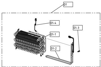
| D1 | 3017070000 | EVA AS | RFP-301(230V 130W) | 1 | |
| D1-1 | 3017070100 | EVA SAS | RFP-301 | 1 | |
| D1-2 | 3012831200 | HEATER SHEATH AS | RFP-301, 230V, 130W | 1 | |
| D1-3 | 4856813100 | CABLE TIE | DA-140 | 1 | |
| D1-4 | 3012764100 | HARNESSE SENS | RFP-340(NBC-K43-24) | 1 | |
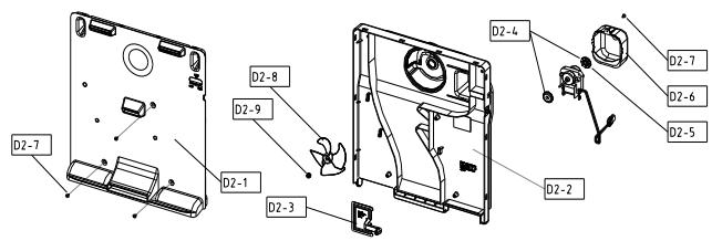
| D2 | 3018932500 | LOUVER F AS | RFP-301(AC 230V 50HZ) | 1 | |
| D2-1 | 3018932300 | LOUVER F A | PP | 1 | |
| D2-2 | 3018932400 | LOUVER F B | PP | 1 | |
| D2-3 | 3013415800 | KNOB F CONTL | PP | 1 | |
| D2-4 | 301107100 | ABSORBER F MOTR | NBR | 2 | |
| D2-5 | 3015922200 | MOTOR F AS | AC220V/50HZ,2500RPM(S6111BDF04) | 1 | |
| D2-6 | 3010664700 | BRACKET FAN MOTR | PP, T2.0 | 1 | |
| D2-7 | 7112401211 | SCREW TAPPING | T1 TRS 4*12 MFZN | 4 | |
| D2-8 | 3011835900 | FAN | OD100,SHAFT OD3.17 | 1 | |
| D2-9 | 3011200510 | CLAMP FAN | SUS 304 (SPRING) | 1 | |
| D3 | 301119V200 | CASE F A | GPPS(GRYSTAL) | 1 | |
| 301119V210 | GPPS(GRAY) | |
| 301119V220 | GPPS(BLUE) | |
| D4 | 3017861500 | SHELF GLAS F | T3.2 RFP-301 | 2 | |
| D5 | 301119V100 | CASE F A | GPPS(GRYSTAL) | 2 | |
| 301119V110 | GPPS(GRAY) | |
| 301119V120 | GPPS(BLUE) | |
| D6 | 3011187310 | CASE ICING AS | | | |
| | | | | |
| | | | | |
| | | | | |
- Please check the color, some parts code color dependent.
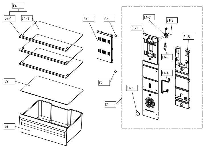
| NO | PART-CODE | PART NAME | SPEC. | Q'ty |
| RN-34* | |
| E1 | 301149C430 | COVER M/FLOW DUCT AS | RFP-311 | 1 | |
| E1-1 | 301149C300 | COVER M/FLOW DUCT | HIPS | 1 | |
| E1-2 | 3017903900 | SOCKET LAMP AS | AC250V | 1 | |
| E1-3 | 7121300811 | SCREW TAPPING | T2S PAN 3X8 MFZN | 2 | |
| E1-4 | 3014811310 | SENSOR R AS | RFP-311(PBN-43) | 1 | |
| E1-5 | 3013387900 | INSU M/FLOW DUCT | F-PS | 1 | |
| E1-6 | 3013416300 | KNOB R CONTL | HIPS,RFP-311 | 1 | |
| E1-7 | 3013600020 | LAMP AS | 240V/15W(E14,CCTA) | 1 | |
| E2 | 3010924600 | CAP F LOUVER | HIPS T2.3 | 2 | |
| E3 | 3015523800 | WINDOW M/FLOW DUCT | GPPS | 1 | |
| E4 | 3017861100 | SHELF R AS | RFP-301 | 3 | |
| E4-1 | 3011664700 | DECO SHELF *F | HIPS | 1 | |
| E4-2 | 3017861200 | SHELF GLAS R | T3.2 | 1 | |
| E5 | 301119V400 | CASE GLAS VEGTB | T3.2 | 1 | |
| E6 | 301119V000 | CASE VEGTB | GPPS(CRYSTAL) | 1 | |
| GPPS(GRAY) | |
| 301119V010 | GPPS(BLUE) | |
| 301119V020 | |
| | | | | |
| | | | | |
- Please check the color, some parts code color dependent.
*Some parts can be changed for improving without notice.