
IHTI9.5ABX - IHTI9.5LBX - Combined refrigerator INDESIT - Free user manual and instructions
Find the device manual for free IHTI9.5ABX - IHTI9.5LBX INDESIT in PDF.
| Product type | Range hood |
| Brand | Indesit |
| Models | IHTI9.5ABX, IHTI9.5LBX |
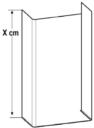
| Height (cm) | 74 to 104 |
| Width (cm) | 90 |
| Depth (cm) | 60 |
| Exhaust tube diameter (cm) | 15 / 12.5 / 12 |
| Usage version | Extracting or recirculating (optional charcoal kit) |
| Number of speeds | 3 speeds + stop |
| Lighting | LED (energy-saving, long lasting) |
| Anti-grease filter | Metal, dishwasher safe |
| Charcoal filter | Replacement every 4 months maximum |
| Power supply | 230 V / 50 Hz (standard) |
| Total power | See rating plate |
| Minimum safety distance | 50 cm (electric hob) / 65 cm (gas) |
| Maintenance of anti-grease filters | Monthly or according to indicator |
| Exterior cleaning | Damp cloth with neutral liquid detergent |
| LED consumption | 90% energy savings compared to traditional bulbs |
| Estimated weight | Approximately 15 kg |
| Standards | EN/IEC 60335, 61591, 60704, etc. |
Frequently Asked Questions - IHTI9.5ABX - IHTI9.5LBX INDESIT
User questions about IHTI9.5ABX - IHTI9.5LBX INDESIT
0 question about this device. Answer the ones you know or ask your own.
Ask a new question about this device
Download the instructions for your Combined refrigerator in PDF format for free! Find your manual IHTI9.5ABX - IHTI9.5LBX - INDESIT and take your electronic device back in hand. On this page are published all the documents necessary for the use of your device. IHTI9.5ABX - IHTI9.5LBX by INDESIT.
USER MANUAL IHTI9.5ABX - IHTI9.5LBX INDESIT
natural_image
Line drawing of a washing machine with a hand inserting a bandage into it (no text or symbols)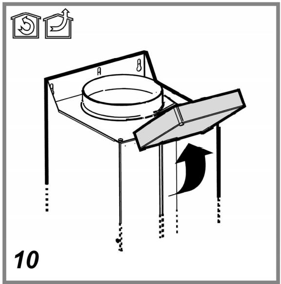
natural_image
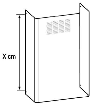
Simple line drawing of a rectangular container with a vertical dimension labeled 'X cm' (no text or symbols on the diagram itself)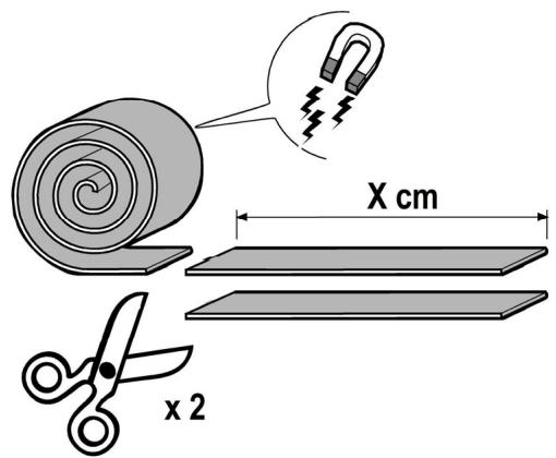
natural_image
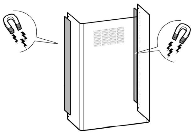
Diagram of a server rack with two hanging clips attached to the side panel (no text or symbols present)19
natural_image
Technical line drawing of a mechanical lifting or lifting system with no visible text or symbols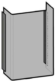
natural_image
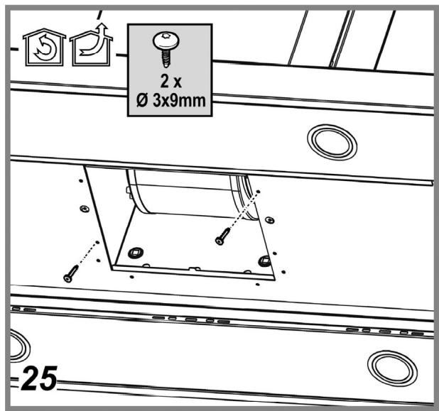
3D diagram of a rectangular panel with a U-shaped cutout and dashed line indicating a dimension (no text or symbols)4 x ∅ 3x9
natural_image
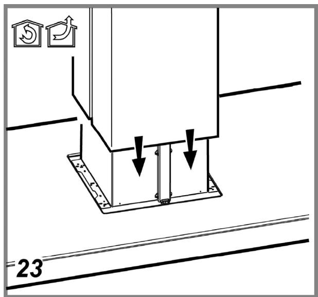
Technical line drawing of a mechanical assembly with no visible text or symbols20

natural_image
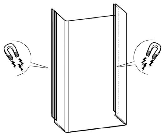
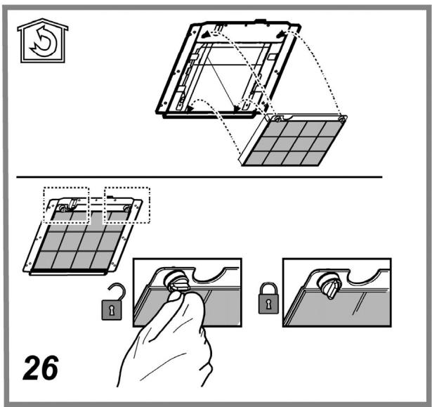
Diagram of a rectangular panel with two hanging clips attached to its sides, showing internal structure and spring-like details (no text or symbols)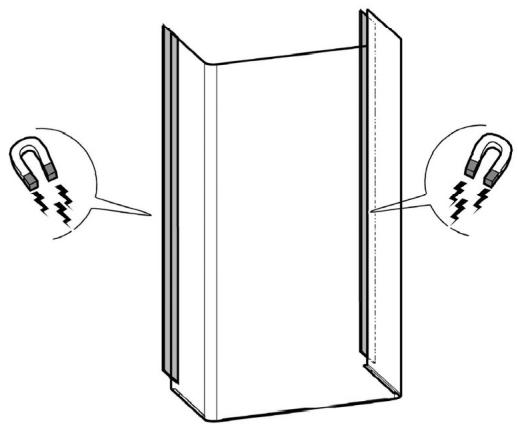
natural_image
Diagram of a rectangular panel with two hanging clips attached to its sides (no text or symbols)21
natural_image
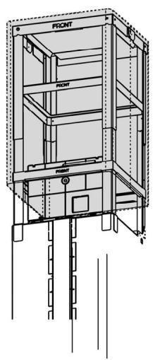
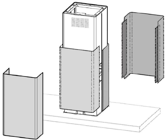
Technical line drawing of a multi-tiered industrial cabinet or enclosure with internal components, shown in 3D perspective (no text or symbols)22

⚠ SICUREZZA GENERALE
natural_image
Illustration showing two hands performing a manual tool manipulation technique (no text or symbols present)- Before any cleaning or maintenance operation, disconnect hood from the mains by removing the plug or disconnecting the mains electrical supply.
- Always wear work gloves for all installation and maintenance operations.
- This appliance can be used by children aged from 8 years and above and persons with reduced physical, sensory or mental capabilities or lack of experience and knowledge if they have been given supervision or instruction concerning use of the appliance in a safe way and understand the hazards involved.
- Children shall not be allowed to tamper with the controls or play with the appliance.
- Cleaning and user maintenance shall not be made by children without supervision.
- The premises where the appliance is installed must be sufficiently ventilated, when the kitchen hood is used together with other gas combustion devices or other fuels.
- The hood must be regularly cleaned on both the inside and outside (AT LEAST ONCE A MONTH).
- This must be completed in accordance with the maintenance instructions provided. Failure to follow the instructions provided regarding the cleaning of the hood and filters will lead to the risk of fires.
- Do not flambé under the range hood.
- For lamp replacement use only lamp type indicated in the Maintenance/Replacing lamps section of this manual.
The use of exposed flames is detrimental to the filters and may cause a fire risk, and must therefore be avoided in all circumstances.
Any frying must be done with care in order to make sure that the oil does not overheat and ignite.
CAUTION: Accessible parts of the hood may become hot when used with cooking appliances.
- Do not connect the appliance to the mains until the installation is fully complete.
- With regards to the technical and safety measures to be adopted for fume discharging it is important to closely follow the regulations provided by the local authorities.
- The air must not be discharged into a flue that is used for exhausting fumes from appliance burning gas or other fuels.
- Do not use or leave the hood without the lamp correctly mounted due to the possible risk of electric shocks.
- Never use the hood without effectively mounted grids.
- The hood must NEVER be used as a support surface unless specifically indicated.
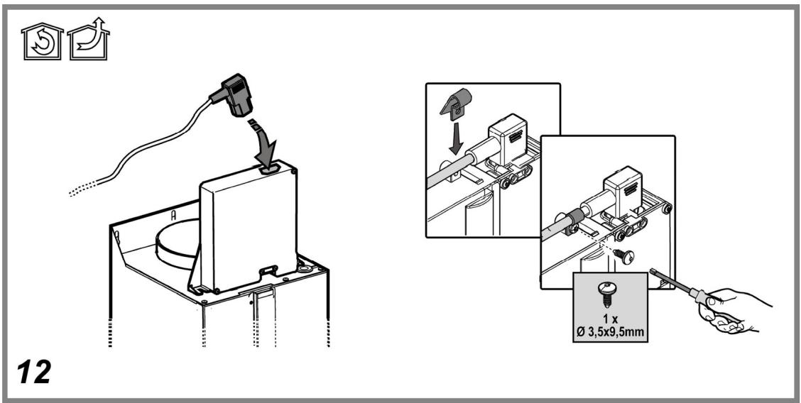
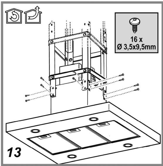
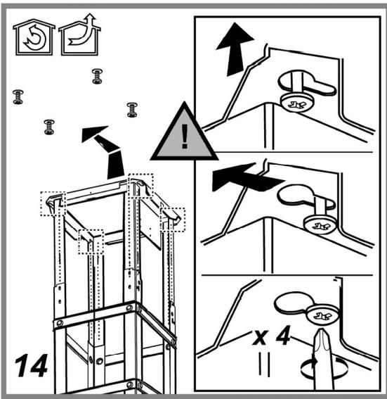
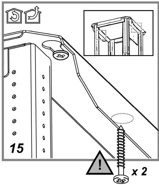
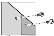
- Use only the fixing screws supplied with the product for installation or, if not supplied, purchase the correct screws type.
- Use the correct length for the screws which are identified in the Installation
Guide.
- In case of doubt, consult an authorized service assistance center or similar qualified person.
WARNING!
- Failure to install the screws or fixing device in accordance with these instructions may result in electrical hazards.
- Do not use with a programmer, timer, separate remote control system or any other device that switches on automatically.
The hood can look different to that illustrated in the drawings in this booklet. The instructions for use, maintenance and installation, however, remain the same.
Closely follow the instructions set out in this manual. All responsibility, for any eventual inconveniences, damages or fires caused by not complying with the instructions in this manual, is declined. This appliance is intended to be used in household and similar application such as: - staff kitchen areas in shop, offices and other working environments; - farm houses; - by clients in hotels, motels and other residential type environments; - bed and breakfast type environments.
- It is important to conserve this booklet for consultation at any moment. In the case of sale, cession or move, make sure it is together with the product.
- Read the instructions carefully: there is important information about installation, use and safety.
- Do not carry out electrical or mechanical variations on the product or on the discharge conduits.
- Before proceeding with the installation of the appliance verify that there are no damaged all components. Otherwise contact your dealer and do not proceed with the installation.
The minimum distance between the supporting surface for the cooking equipment on the hob and the lowest part of the range hood must be not less than 50cm from electric cookers and 65cm from gas or mixed cookers.
If the instructions for installation for the gas hob specify a greater distance, this must be adhered to.
ELECTRICAL CONNECTION
The mains power supply must correspond to the rating indicated on the plate situated inside the hood. If provided with a plug connect the hood to a socket in compliance with current regulations and positioned in an accessible area, after installation. If it not fitted with a plug (direct mains connection) or if the plug is not located in an accessible area, after installation, apply a double pole switch in accordance with standards which assures the complete disconnection of the mains under conditions relating to over-current category III, in accordance with installation instructions.
▲ WARNING!
Before re-connecting the hood circuit to the mains supply and checking the efficient function, always check that the mains cable is correctly assembled.
Replacing the power cable
The hood is provided with a special power cable; if the cable is damaged, request a new one from Technical Service.
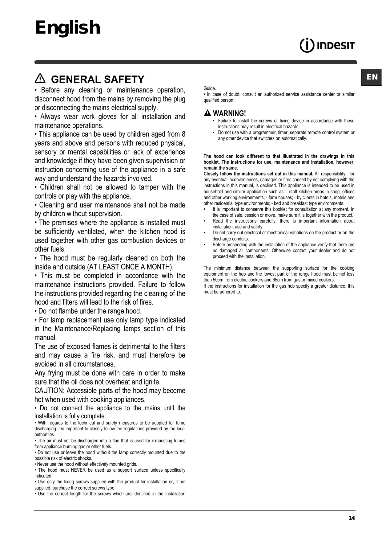
AIR VENT
(for the suction versions)
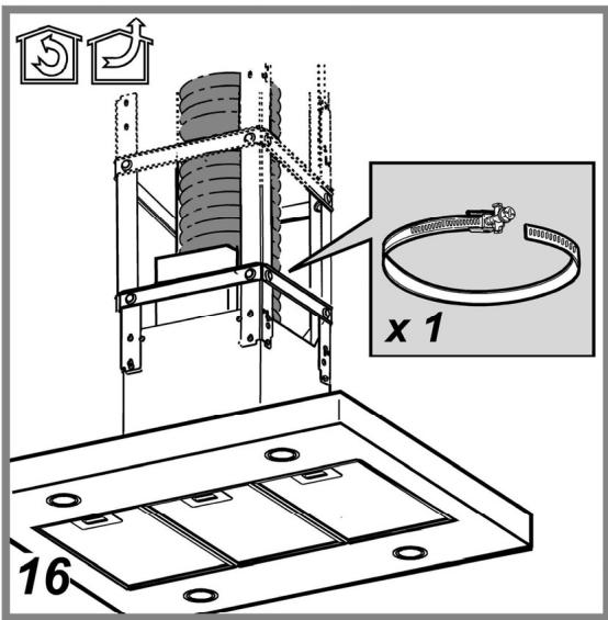
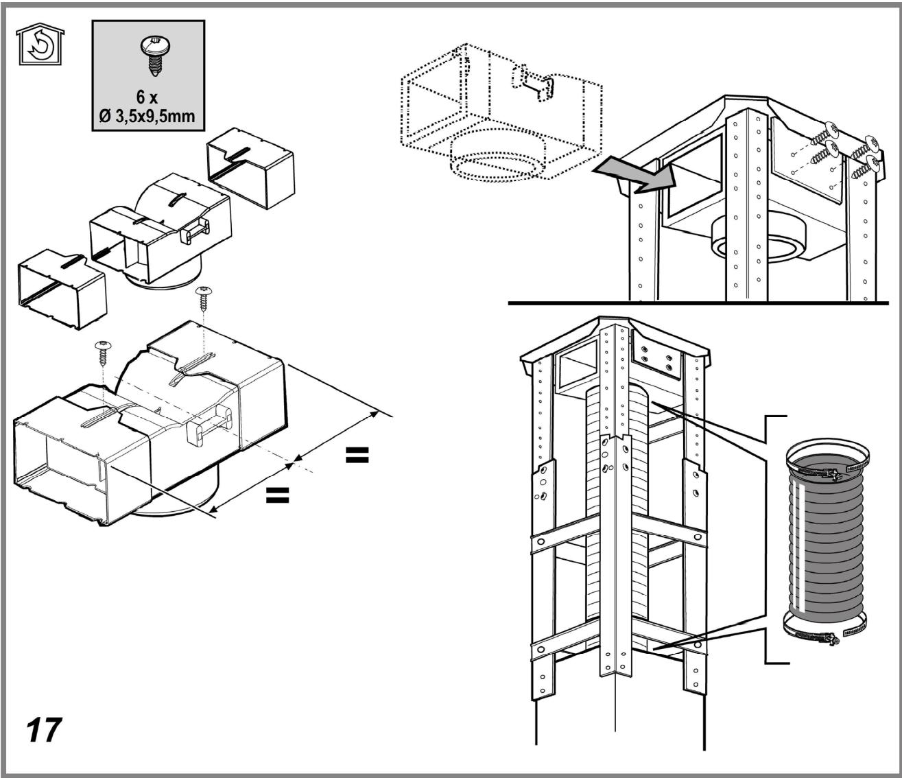
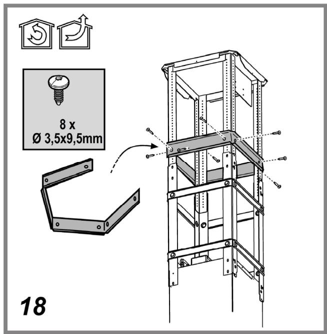
Connect the hood and discharge holes on the walls with a diameter equivalent to the air outlet (connection flange).
Using the tubes and discharge holes on walls with smaller dimensions will cause a diminution of the suction performance and a drastic increase in noise.
Any responsibility in the matter is therefore declined.
! Use a duct of the minimum indispensable length.
! Use a duct with as few elbows as possible (maximum elbow angle: 90°).
! Avoid drastic changes in the duct cross-section.
! The company declines any responsibility whenever these regulations are not respected.
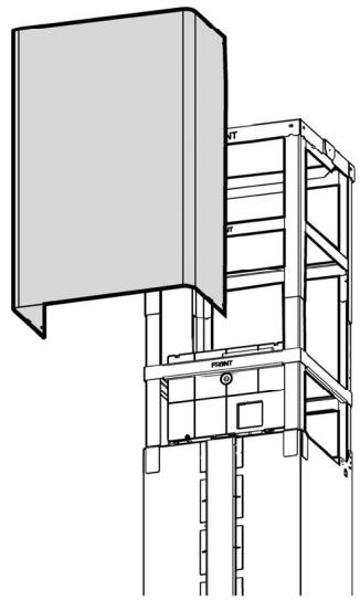
FILTERING OR DUCTING?
! Your cooker hood is ready to be used in suction version.
To use the hood in filtering version the special ACCESSORY KIT must be installed.
Check on the first pages of this manual if the ACCESSORY KIT is furnished or must be bought separately.
Note: If furnished, in certain cases, the additional activated carbon filtering system may be installed on the hood.
Information about the conversion of the hood from suction version to filtering version is present in this manual.

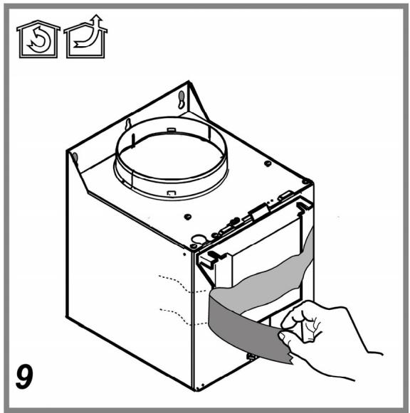
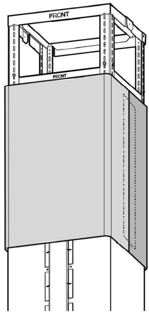
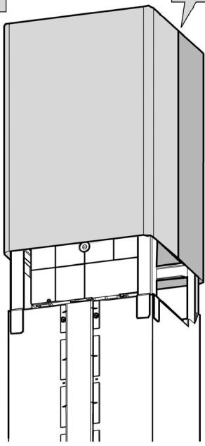
Ducting version
In this case the fumes are conveyed outside of the building by means of a special pipe connected with the connection ring located on top of the hood.
CAUTION!
The exhausting pipe is not supplied and must be purchased apart.
Diameter of the exhausting pipe must be equal to that of the connection ring.
CAUTION!
If the hood is supplied with active charcoal filter, then it must be removed.

Filter version
The aspirated air will be degreased and deodorised before being fed back into the room.
In order to use the hood in this version, you have to install a system of additional filtering based on activated charcoal.
CONTROLS
The hood is fitted with a control panel with aspiration speed selection control and a light switch to control cooking area lights.
Models with mechanical control panel
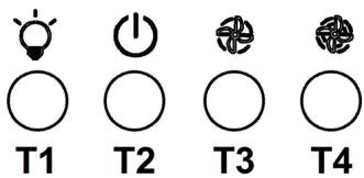
T1. ON/OFF light switch
T2. Speed 1/OFF switch
T3. 2-speed selection
T4. 3-speed selection
MAINTENANCE
Cleaning
Clean using ONLY a cloth dampened with neutral liquid detergent. DO NOT CLEAN WITH TOOLS OR INSTRUMENTS. Do not use abrasive products. DO NOT USE ALCOHOL!
Perimeter aspiration panel
Clean the perimeter aspiration panel with the same frequency as the ant-fats filter, using a cloth and not too concentrated liquid detergent. Do not use abrasive substances.
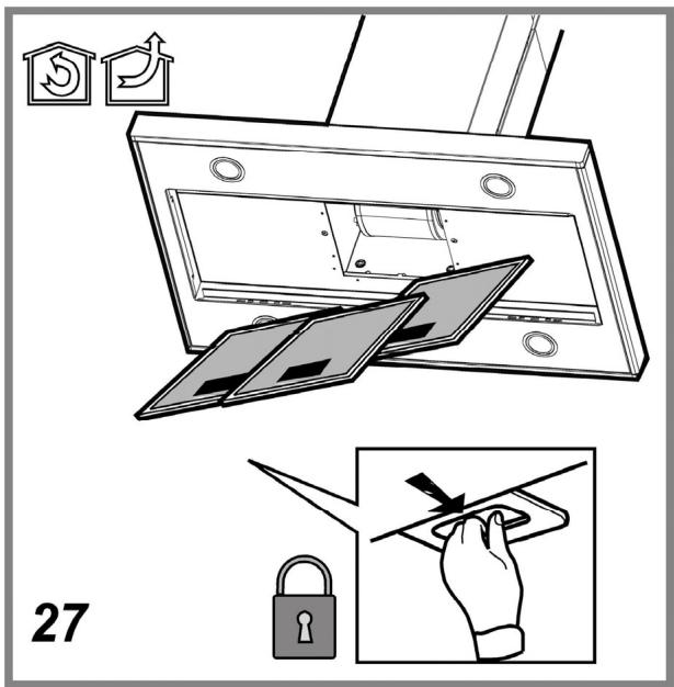
Maintenance of the anti-grease filters
Traps cooking grease particles.
This must be cleaned once a month (or when the filter saturation indication system – if envisaged on the model in possession – indicates this necessity) using non aggressive detergents, either by hand or in the dishwasher, which must be set to a low temperature and a short cycle.
When washed in a dishwasher, the grease filter may discolor slightly, but this does not affect its filtering capacity.
To remove the grease filter, pull the spring release handle.
natural_image
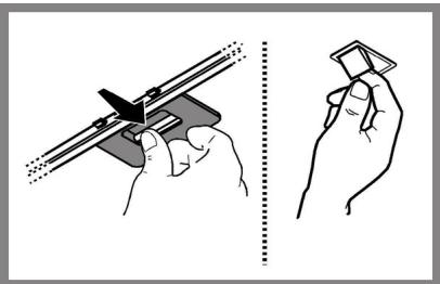
Illustration showing two hand positions: one holding a tool with a triangular cutout, the other holding a small object (no text or symbols present)Maintenance of the charcoal filter
It absorbs unpleasant odors caused by cooking.
The saturation of the charcoal filter occurs after more or less prolonged use, depending on the type of cooking and the regularity of cleaning of the grease filter.
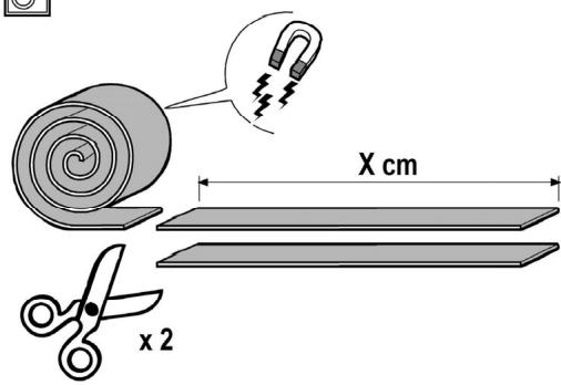
In any case it is necessary to replace the cartridge at least every four months (or when the filter saturation indication system – if envisaged on the model in possession – indicates this necessity). The charcoal filter may NOT be washed or regenerated.
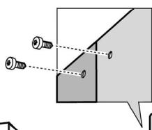
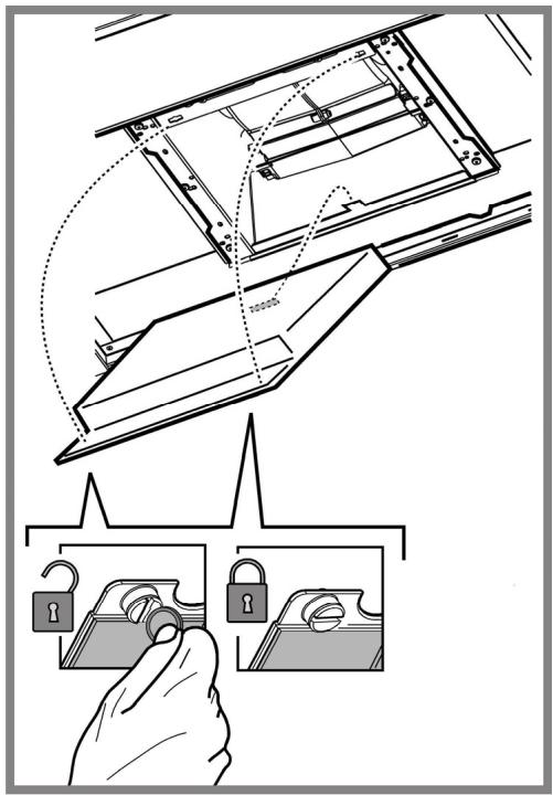
Assembly
Hook the charcoal filter at the back on the metal tongue of the hood first, then on the front with the two knobs.
Disassembly
Remove the charcoal filter by turning the knobs fixing it to the hood by 90^ .
Replacing lamps
The hood is equipped with a lighting system based on LED technology. The LEDs guarantee an optimum lighting, a duration up to 10 times as long as the traditional lamps and allow to save 90% electrical energy.
For replacement, contact the technical service.
DISPOSAL
- This appliance is marked according to the European directive 2012/19/EC on Waste Electrical and Electronic Equipment (WEEE).
- By ensuring this product is disposed of correctly, you will help prevent potential negative consequences for the environment and human health, which could otherwise be caused by inappropriate waste handling of this product.

- The symbol ■ on the product, or on the documents accompanying the product, indicates that this appliance may not be treated as household waste. Instead it should be taken to the appropriate collection point for the recycling of electrical and electronic equipment. Disposal must be carried out in accordance with local environmental regulations for waste disposal.
- For further detailed information regarding the process, collection and recycling of this product, please contact the appropriate department of your local authorities or the local department for household waste or the shop where you purchased this product.
Appliance designed, tested and manufactured according to:
• Safety: EN/IEC 60335-1; EN/IEC 60335-2-31, EN/IEC 62233.
- Performance: EN/IEC 61591; ISO 5167-1; ISO 5167-3; ISO 5168; EN/IEC 60704-1; EN/IEC 60704-2-13; EN/IEC 60704-3; ISO 3741; EN 50564; IEC 62301.
- EMC: EN 55014-1; CISPR 14-1; EN 55014-2; CISPR 14-2; EN/IEC 61000-3-2; EN/IEC 61000-3-3. Suggestions for a correct use in order to reduce the environmental impact: Switch ON the hood at minimum speed when you start cooking and kept it running for few minutes after cooking is finished. Increase the speed only in case of large amount of smoke and vapor and use boost speed(s) only in extreme situations. Replace the charcoal filter(s) when necessary to maintain a good odor reduction efficiency. Clean the grease filter(s) when necessary to maintain a good grease filter efficiency. Use the maximum diameter of the ducting system indicated in this manual to optimize efficiency and minimize noise.
MALFUNCTIONS
If something appears not to be working properly, do the following simple checks before calling Technical Service:
• If the hood is not working:
Check that:
- The power has not been disconnected.
- A speed has been selected.
• If the hood performs inefficiently:
Check that:
- The motor speed selected is sufficient for the amount of smoke and vapours released.
- The kitchen is sufficiently ventilated to allow air intake.
- The charcoal filter is not worn (hood in filtering version).
• If the hood has turned off during normal functioning:
Check that:
- The power has not been disconnected.
- the omnipolar disconnection device has not tripped.
If the hood fails to operate correctly, briefly disconnect it from the mains power supply for almost 5 sec. by pulling out the plug. Then plug it in again and try once more before contacting the Technical Assistance Service.
TECHNICAL DATA
| Model | Height (cm) | Width (cm) | Tiefe (cm) | ∅ of exhaust tube (cm) |
| IHTI 9.5 L B X | 74 – 10476 –104 | 90 | 60 | 15-12,5-12 |
Please check the plate in order to verify the total absorption and the light absorption.


Components not provided with the product
natural_image
Illustration showing two hands holding a tool and a small object, with no visible text or symbols.Ersetzen der Lampen
natural_image
Illustration showing two hand positions: one holding a tool with a triangular cutout, the other holding a small object (no text or symbols present)natural_image
Illustration showing two hands performing a manual tool manipulation technique (no text or symbols present)natural_image
Illustration showing two hand positions: one holding a tool with a cutting edge, the other holding a small object (no text or symbols present)Vervanging lampjes
natural_image
Illustration showing two hand positions: one holding a tool with a bracket, the other holding a small object (no text or symbols present)natural_image
Illustration showing two hand positions: one holding a tool with a triangular cutout, the other holding a small object (no text or symbols present)Замена ламп
natural_image
Illustration showing two hands holding a tool and a small object, with no visible text or symbols.Wymiana żarówek
natural_image
Illustration showing two hand positions: one holding a tool, the other holding a paper (no text or symbols present)Výměna svítidel
natural_image
Illustration showing two hands performing a manual tool manipulation technique (no text or symbols present)Výmena žiaroviek
Odsávač pary je vybavený systémom osvetlenia založenom na technoloógii LED.
natural_image
Illustration showing two hands performing a manual tool manipulation (no text or symbols present)Izzók cseréje
- ⚠ SICUREZZA GENERALE
- WARNING!
- ELECTRICAL CONNECTION
- ▲ WARNING!
- Replacing the power cable
- AIR VENT
- FILTERING OR DUCTING?
- Ducting version
- CAUTION!
- Filter version
- CONTROLS
- MAINTENANCE
- Cleaning
- Perimeter aspiration panel
- Maintenance of the anti-grease filters
- Maintenance of the charcoal filter
- Assembly
- Disassembly
- Replacing lamps
- DISPOSAL
- MALFUNCTIONS
- Ersetzen der Lampen
- Vervanging lampjes
- Замена ламп
- Wymiana żarówek
- Výměna svítidel
- Výmena žiaroviek
- Izzók cseréje
Brand : INDESIT
Model : IHTI9.5ABX - IHTI9.5LBX
Category : Combined refrigerator