USER MANUAL GAIN D20 - GAIN D30 - GAIN D40 ORBEA
Orbea lifetime warranty
Mahle Ebikemotion components warranty
Warranty claim process
03 MAINTENANCE 8
Keep your bicycle clean
Keep your drivetrain lubricated
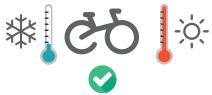
Inspect your bicycle before every ride
Maintenance schedule
Replacement parts
After a crash or an impact
04 USE WARNINGS. GAIN 12
Maximum tyre width
Minimum seatpost insertion
Maximum number of headset spacers
Headset spacers above the stem. Position of the carbon expander
Intended use
05 USE WARNINGS. MAHLE EBIKEMOTION X35 SYSTEM 14
Battery and electric components care
Components installation
Lights
Range
Electric bicycle battery transport
Electric bicycle transport
Charging the battery
Battery level visualization (during use)
Turning the system on/off and changing the assist level
Turning the lights on/off
System errors
07 MAHLE EBIKEMOTION MOBILE USER APP 20
App installation and registration
Creating a new account
App diagram
Language
Units
Pairing a bicycle
Main features
System alerts
User app troubleshooting and error codes
08 MAHLE EBIKEMOTION WEB DASHBOARD 32
Register as the bicycle owner
09 MAHLE EBIKEMOTION DEALER MOBILE APP 33
10 GEOMETRY AND SIZING 34
11 TECHNICAL SPECIFICATIONS 35
Gain Hydro technical specifications
Mahle Ebikemotion X35 system technical specifications
12 ASSEMBLY AND SPARES 40
Headset
Cutting the fork steerer tube
13 MAHLE EBIKEMOTION X35 SYSTEM 53
Components connection diagram
Spares
Range extender
X35 system cable routing on Gain Hydro
Components assembly warning
ANT+ connectivity
14 LIGHTS 63
Lights specifications
Installation diagram and components
Lights cabling
15 DECLARATION OF COMFORMITY 66
16 ADDITIONAL INFORMATION 67
01 INTRODUCTION
This technical manual contains important information about your bicycle, its use, maintenance and replacement parts. Please read it carefully.
This document is a supplement to the General User's Manual for Orbea bicycles and components, which describes in a more detailed manner their appropriate use and the adjustment of the general components of the bicycles for safe riding and operation. You can see and download the User's Manual and the rest of the technical manuals for Orbea products from our website:
You can consult the information on the use, maintenance and characteristics of the components of other manufacturers that are assembled on our bicycles, such as wheels, handlebars, pedaling assistance systems, suspension forks, etc, on the manufacturer's website or through their dealer in your country.
KEY TO SYMBOLS
Throughout this technical manual, various symbols are used that indicate instructions and warnings for use, maintenance and assembly. Pay attention to these symbols to avoid hazardous situations and ensure the correct use and assembly of all components.
The meaning of these symbols is explained below. In this manual, the symbol may appear accompanied only by the relevant instruction for the component described. Read the following information carefully in order to understand their meanings.
SAFETY INSTRUCTIONS

DANGER: Immediately hazardous situation. If not avoided, serious injury or even death will occur.

WARNING: Potentially hazardous situation. If not avoided, serious injury or even death may occur.

CAUTION: Potentially hazardous situation. If notavoided, minor or moderate injury may occur.

Not related to injury. Property situation hazard.

RISK OF ELECTRIC SHOCK: Dangerous situation. If not avoided, may cause serious injuries, or even death, due to electric shock.

RISK OF SHORT CIRCUIT: Not observing the indications may cause components to short circuit. Potential damage to components and fire hazard.
The symbols DANGER and WARNING inform about a dangerous situation that, if not avoided, may cause an accident. An accident while riding a bicycle always poses risk of serious injury or even death. In this manual, the risk of death may therefore not always be mentioned when these symbols appear, since the risk is explained here.

SPANNER

TORX KEY

ALLEN KEY

PHILLIPS
SCREWDRIVER

The key number is indicated inside the symbol.

10 N.m
TIGHTENING TORQUES: The corresponding tightening torque (in Newtons/meter) is indicated beneath the symbol of the tool to use for the element described.
ASSEMBLY COMPOUNDS

OIL: Light lubrication of elements like chains and cables.

GREASE: High quality assembly grease to avoid creaking and seizing.

CARBON PASTE: Carbon fiber assembly compound to increase friction between carbon fiber components.

LOCTITE SERIES 600: Fixing cylindrical surfaces.

LOCTITE SERIES 200: Threadlock. Medium resistance.

LOCTITE SERIES 400: Instant adhesive.
02 ORBEA WARRANTY
Our continuous daily effort to provide maximum quality of our bicycles allows us to offer the following warranty and coverage conditions:
LEGAL WARRANTY
Orbea offers the original owner of the Orbea bicycle, rigid fork or original component a legal warranty of 2 years from the date of purchase of the items, or the period stipulated as the legal warranty in the country of purchase.
This warranty covers all Orbea products against manufacturing defects and/or lack of compliance and guarantees the repair or replacement of the defective product at no cost to the affected customer. Likewise, this warranty also covers paint, varnish and corrosion defects on all frames and rigid forks assembled on our bicycles during the period specified in the previous paragraph of this warranty.
This warranty does not cover in any case damage derived from inappropriate use, falls or accidents or the lack of maintenance, as well as the normal wear and tear of consumable parts, such as, by way of example, but without limitation: seals, bearings, handlebar tape, spokes, tires, saddles, etc.
For a full description of the coverage conditions and the legal warranty, please visit:
As a supplement to the legal warranty, Orbea offers the original buyer of the bicycle the Orbea lifetime commercial warranty, as long as they have registered their product on the Orbea website within 30 days of its purchase. This lifetime warranty covers the frames and rigid forks that we mount on our bicycles against manufacturing defects and material conformity issues with no time limitation.
This warranty extends the original period of coverage against paint, varnish or corrosion defects on the frames and rigid forks for one additional year after the end of the legal warranty period.
Orbea's lifetime commercial warranty only covers frames and rigid forks, but not OC components.
For a full description of the warranty conditions for the lifetime warranty, please visit:
www.orbea.com/es-es/garantia/#garantia-deporvida-orbea
REGISTER YOUR BICYCLE
In order to benefit from the Orbea lifetime warranty extension, you must register your bicycle within 30 days of its purchase at:
The MAHLE Ebikemotion components are covered by the legal 2 year warranty, or the legal warranty period on the country of purchase, valid from the date of purchase of the components or the bicycle they are assembled on.
This warranty covers all MAHLE Ebikemotion products against manufacturing defects or lack of conformity and gives the owner of the bicycle or the component the right to have the component repaired or replaced without any additional cost derived from this warranty.
This warranty does not cover in any case damages derived from inadequate use, falls or accidents, incorrect assembly, lack of maintenance or not observing the recommendations of use, storage, charge, etc. described in this manual.
The natural aging of the MAHLE Ebikemotion batteries and loss of capacity due to normal use, charge and storage are not covered by the conditions of the warranty.
WARRANTY CLAIM PROCESS
All warranty claims must be processed through an authorized Orbea dealer, who will perform the initial diagnosis and send Orbea all the necessary documentation for a complete diagnosis of the claim in question. The dealer will inform the owner about the status of the process and the decision made on the warranty claim by Orbea.
We recommend that you always visit the dealer where you purchased your bicycle to process a warranty claim, or the dealer you chose during the process of purchasing a bicycle that was delivered directly to your home. If you cannot visit the original dealer, you can check the list of authorized dealers on our website or contact Orbea directly so we can indicate the dealer you should visit.
Orbea products are carefully designed to be long-lasting, efficient and easy to maintain. The carbon and aluminum frames and forks are extremely corrosion-resistant.
However, your bicycle needs regular maintenance of its components in order to ensure that it works properly and safely, and to ensure its longevity.
KEEP YOUR BICYCLE CLEAN
Clean your bicycle with mild soap and water on a regular basis to keep it working like new, and check the condition of the frame and its components. Do not use pressurized water, since it could damage components like bearings or the tubes of the frame.
Citrus-based degreasers are biodegradable and very effective in removing grease from drivetrain components and the chain.

Accumulated dirt can complicate the visual inspection of the components and hide damage that could potentially cause malfunctions or accidents.
NOTICE
Built-up dirt causes the premature wear of components and can even damage the bicycle frame in areas such as the bearing housings and moving parts. Damage due to the lack of cleaning and maintenance is not covered by the warranty.
KEEP YOUR DRIVETRAIN LUBRICATED
Once you have cleaned your bicycle, lubricate the drivetrain, specifically the chain. Use the minimum amount necessary to lubricate the links, removing any excess amounts to prevent them from attracting dirt, causing the drivetrain to not work properly and the premature wear of the components.

Avoid the use of aerosol lubricants to prevent them from adhering to the brake surfaces. Always check the brakes after lubricating the drivetrain.
INSPECT YOUR BICYCLE BEFORE EVERY RIDE
Do a quick check before each ride to make sure that your bicycle is in optimal operating conditions. You might discover small problems that could turn into major issues during the ride.
FRAME: Inspect the frame and the fork, looking for cracks or other damage. No strange noises should be heard. In the event of any damage to the frame, avoid using the bicycle and contact your authorized dealer for inspection.
CHAIN: Ensure it's clean and lubricated. The drivetrain should not make any abnormal noises.
BRAKES: Check that the brakes operate properly and in a safe manner. Check the tightening torques of the components.
TIRES: Check for worn tires and look for cuts on the tread or sides. If you spot damage, replace the tire. Make sure that the tire pressure is adequate.
WHEELS: Check that the wheels turn smoothly and show no signs of lateral deviations. Turn the wheel slightly from side to side to check that there is no lateral play in the bearings. Make sure that there are no broken or loose spokes. Check that the axles or quick-release levers are securely tightened with the correct tightening torque.
HEADSET: Activate the front brake and move the front part of the bicycle back and forth, applying pressure on the handlebars with the rear wheel on the ground. Check for strange noises or movement of the headset, which could indicate that the bearings are worn or the headset has not been correctly tightened. Once the headset is correctly adjusted, check that it turns smoothly.
LINKAGE PIVOT POINTS: On full suspension bicycles, check that all the linkage pivot points rotate smoothly and show no signs of play in the bearings. Pull the linkages from side to side on the bicycle and pay attention to any noise or play at the pivot points. If the linkages do not operate smoothly or show signs of play, it could be a sign that the tightening torques are incorrect or that the bearings are worn or damaged.
BEARINGS: The bearings (bottom bracket, linkage pivot points, headset, wheels, etc.) are elements subject to wear that must be inspected on a regular basis to ensure that they operate correctly. Bearings in poor condition can damage the components in which they are installed. Adverse weather conditions speed up bearing wear. Bearings that have excessive play or that do not turn smoothly must be replaced immediately. In the case of any doubt, consult your authorized dealer.
NOTICE
Damage to components like the frame, bicycle wheels, etc. associated with the lack of maintenance and the replacement of the bearings are not covered by the warranty conditions.
PEDELEC SYSTEM: Turn the bicycle on and check that the system is showing no errors (pink light on the Iwoc One/Trio). Ensure that the system assists normally and that all functions (assist level change, lights, etc.) work correctly.

Failure to follow the recommendations outlined in this manual and riding a bicycle that shows signs of the symptoms described above may cause accidents and serious injuries.

TIGHTENING TORQUES. Always check the tightening torques and install the components described in this manual according to the tightening torque specifications. Follow the tightening torque specifications for components from other manufacturers installed on your Orbea bicycle. The failure to follow these specifications may lead to the malfunction of the components, accidents and even death.
MAINTENANCE SCHEDULE
NOTICE
Maintenance periods for the components indicated below are general guidelines and largely depend on factors such as weather conditions in which your bicycle is ridden (adverse conditions considerably reduce the life of the components and increase maintenance frequency), the cleanliness of your bicycle and its components (components with accumulated dirt wear more quickly), and use (more demanding use of the bicycle will require more frequent maintenance periods).
For components from other brands mounted on Orbea bicycles, you can check the recommended or mandatory maintenance periods on the manufacturer's website or by contacting the distributor of that brand in your country.
NOTICE
Damage to components as a result of failing to follow the recommended maintenance periods could result in damage that is not covered by the warranty conditions of Orbea or the component manufacturer.

The failure to comply with maintenance periods could result in damage to the components and lead to malfunctions and accidents.
HEADSET:
- Inspection of its operation before each ride.
- Disassembly and manual inspection of the bearings once every 6 months of use.
BOTTOM BRACKET:
- Inspection of its operation before each ride.
- Disassembly and manual inspection of the bearings once every 6 months of use.
DRIVETRAIN:
- Inspection of its operation before each ride.
- Regular inspection of chain wear every 500 km. A chain that is worn beyond the manufacturer's recommendations must be replaced to prevent damage to the rest of the drivetrain components. The failure to observe the manufacturer's recommendations in terms of wear could necessitate the replacement of the rest of the parts of the drivetrain.
WHEELS:
- Inspection of its operation before each ride.
- Disassembly and manual inspection of the bearings and all components once every 6 months.
SHOCKS AND SUSPENSION FORKS:
- Inspection of its operation before each ride.
- Inspection and full maintenance every 125 hours or once a year (whichever occurs first) by the manufacturer's authorized dealer.
TELESCOPIC SEAT POSTS:
- Inspection of its operation before each ride.
- Inspection and full maintenance every 125 hours or once a year (whichever occurs first) by the manufacturer's authorized dealer.
PIVOT POINTS ON FULL SUSPENSION FRAMES:
- Inspection of its operation before each ride.
- Disassembly of the frame and the manual inspection of all the bearings every 125 hours of use or once a year (whichever occurs first). These times may be shorter depending on the conditions in which the bicycle is ridden. More demanding use of the bicycle or use in adverse weather conditions or in mud requires the disassembly and inspection of the frame once every 75 hours of use or once every 6 months (whichever comes first). If a bearing does not turn smoothly or has excessive play, it must be replaced immediately.
GEAR CABLES AND HOUSING:
- Inspection of its operation before each ride.
- Replacement of gear cables every 6 months to 1 year depending on the conditions in which the bicycle is used.
BRAKES:
- Inspection of the operation and wear of the brake pads or shoes before each ride.
- Check the wear on disc brakes and the cables or hydraulic lines every 6 months to 1 year depending on the conditions in which the bicycle is used. Flush the hydraulic lines once a year.
PEDELEC SYSTEM COMPONENTS:
- Regularly check the connections and cables of the ebike system components. The connections must be clean and free of debris and foreign objects. The cables must be in good condition and free of cuts or kinks and bends that may cause short circuits and lack of electric assistance.
- The exterior of the controllers and batteries should not show signs of damage that may allow water and other elements to ingress within.
- If you notice any damage to the components, contact your Orbea dealer for a professional diagnosis and/or replacement.
- Read the X35 System Use Warnings section of this manual to know about the correct care and maintenance procedures of the pedelec system components.
ELECTRIC SYSTEM ERRORS.
- Read the Ebikemotion User App section of this manual to know how to identify errors in the system. When facing a system error that cannot be corrected by following the trouble-shooting procedures shown in this section, contact your Orbea dealer for a complete diagnosis of the X35 system.
SYSTEM UPDATES:
- The ebike systems manufacturers may develop improvements and updates of their pedelec systems overtime that improve the system or fix existing problems. Remember to contact Orbea or your authorized dealer to find out if there is any available update for the system on your bike.
- On the MAHLE Ebikemotion X35 system, the updates are performed through the CAN BUS protocol and can only be carried out by an authorized dealer using a specific MAHLE update tool.

Some of these checks and maintenance needs go beyond the mechanical knowledge of most bicycle users. If you are not qualified to perform the necessary maintenance, always visit an Orbea dealer for maintenance on your bicycle and its components. The failure to perform proper maintenance can result in malfunctions and accidents with serious consequences.
NOTICE
Maintenance performed incorrectly can damage the components, which are not covered by the warranty conditions.
REPLACEMENT PARTS
Always use original Orbea or MAHLE original replacement parts or those from the component manufacturer in question.

The use of non-original replacement parts may cause damage that results in malfunctions and accidents with serious consequences.

The installation of some of the replacement parts in this technical manual are beyond the mechanical knowledge of most bicycle users. If you are not qualified to install these replacement parts, always visit an Orbea dealer for maintenance on your bicycle and its components. The failure to properly install replacement parts can result in malfunctions, accidents and serious injuries.
NOTICE
The installation of non-original replacement parts can damage your bicycle and is not covered by the warranty conditions.
AFTER A CRASH OR AN IMPACT
Falling off your bike is part of cycling. If you have an accident on your Orbea bicycle, be sure that you're okay and seek medical care, if necessary. If you are uninjured, you should check the condition of your bicycle before continuing to ride.
INSPECT THE FRAME AND THE BICYCLE COMPONENTS TO SEE IF THEY HAVE BEEN DAMAGED IN ANY WAY
If you detect any problem, do not continue to ride the bicycle.
POINTS TO CHECK
Inspect the frame and the fork to identify whether either of these components have been broken or bent. If you detect any damage or cracks, you must stop using the bicycle immediately. On carbon frames, look for cracks or soft spots in the carbon. If you detect any of these symptoms, you must stop using the bicycle immediately.

The materials used on carbon frames and forks are rigid and strong, but if overloaded or if they suffer an impact, the fibers do not bend, and they will break. A strong enough impact to this material could cause damage that, while not visible at first glance, could cause the materials to fail in the future. In the case of any doubt about the consequences of a fall or accident, contact your Orbea dealer for a correct diagnosis of the materials.
Check the drivetrain and the wheels to make sure that the components operate correctly. If you discover any damage to the components, stop using the bicycle immediately.
Even if you do not observe any damage, pay close attention to the sound of your bicycle when you ride it again. Damage and other problems can cause unusual noises. If you notice any unusual noise, stop using your bicycle immediately and contact your Orbea dealer for a correct diagnosis of the problem.
04 USE WARNINGS. GAIN HYDRO
TAKE YOUR ORBEA BICYCLE TO AN AUTHORIZED DEALER FOR A PROFESSIONAL INSPECTION
Some of the consequences of a fall or accident can only be detected by completely disassembling the bicycle to check for the presence of damage or other signs of deterioration.

A collision or impact can cause serious damage to your bicycle and its components, causing them to malfunction or wear out prematurely. Malfunctions can occur suddenly and without notice, causing you to lose control of your bicycle and suffer serious injuries, or even death.
MAXIMUM TYRE WIDTH
This technical manual specifies the maximum size of the tyres that can be mounted on the frame. Always follow these guidelines when installing tyres on your bicycle.
However, the real measurements of the tyre circumference and width may change from one manufacturer to another. When installing a tyre other than that originally mounted on your Orbea bicycle, check that there is at least 3 mm between the top and the sides of the tyre and any part of the frame.
NOTICE
Damage to the frame or components due to the use of a tyre that does not comply with these measurements is not covered by the warranty conditions.
MINIMUM SEATPOST INSERTION

Always follow the specifications regarding the minimum insertion depth of the seatpost or the frame on road bicycles with exclusive Orbea seatposts. The failure to follow these instructions can cause stresses on the materials beyond the conditions for which they were designed and cause damage not covered by the warranty conditions, as well as accidents that can result in serious injuries.
MAXIMUM NUMBER OF HEADSET SPACERS

Never use more headset spacers below the stem than those specified for the frame. Consult the specifications tables to find out the maximum number of headset spacers that are acceptable for use on an Orbea frame. Installing more spacers than those permitted can stress the materials beyond the use for which they were designed, which can cause accidents and serious injuries.
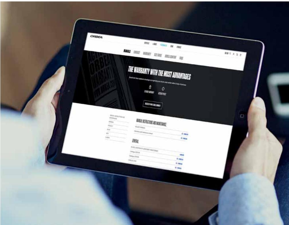
HEADSET SPACERS ABOVE THE STEM. POSITION OF THE CARBON EXPANDER INSIDE CARBON FORKS

Never install headset spacers above the stem. Placing spacers above the stem, especially on forks with a carbon steerer tube, can cause the expander inside the fork tube to be positioned above the lower limit of the steerer tube, which can stress the materials beyond the use for which they were designed, possibly causing accidents and serious injuries.

The length of the fork steerer tube must always be appropriate for the position of the stem in the fork. The stem must always be installed in the steerer tube of the fork so that both fastening bolts on the back of the stem are positioned above the surface of the steerer tube of the fork. Never mount the stem so that the top fastening bolt of the stem remains above the top edge of the fork steerer tube. This will stress the materials beyond the use for which they were designed, possibly causing accidents and serious injuries.
INTENDED USE
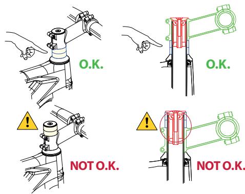
The intended use of all models is ASTM Condition 2, that includes Condition 1 as well as unpaved and gravel roads and trails with moderate grades with drops limited to 15 cm.
For information about all ASTM categories, consult the General User Manual.
For Gain to be used under the conditions observed in the ASTM Condition 2, make sure to use appropriate all-road tyres (wide and with generous tread). Assemblies with road specific tyres should only be used on paved roads under the conditions described by the ASTM Condition 1.
05 USE WARNINGS. MAHLE EBIKEMOTION X35 SYSTEM
BATTERY AND ELECTRIC COMPONENTS CARE
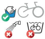
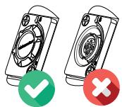
Do not wash your bike with a pressure washer or submerge it or the electric system components. All the pedelec system components have an IP54 water resistance rating that protects them against rain and splashes. However, the use of pressure washers may allow water to ingress into the components and damage them.
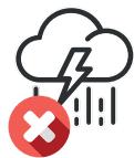
Avoid using your bicycle in extreme weather conditions. All the pedelec system components have an IP54 water resistance rating that protects them against rain and splashes. However, extreme weather conditions may damage the components.
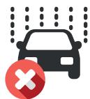
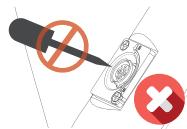
Avoid transporting your bicycle outside your car when it is raining. All the pedelec system components have an IP54 water resistance rating that protects them against rain and splashes. However, the speed of your vehicle may increase the effects of the rain and damage the components.
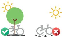
Do not leave your bicycle exposed to high temperatures for long periods of time. It may damage the components on your bicycle.
Observe the recommended temperature ranges of use (discharge), charge and storage (internal battery). The use, charge and storage outside these recommended temperature ranges may affect the battery cells and reduce their life and available range.
TEMPERATURE RANGES
Charge: 10°C - 40°C
Discharge (use) -15°C - 50°C
Storage: 0°C - 30°C
The following table shows the maximum and minimum ranges stated by the cell manufacturer.
Generally, the use, charge and storage of batteries below 0^ C will affect the available range for charge of a battery and overtime may reduce the battery life.

Avoid storing your bicycle (internal battery) or Range Extender for long periods of time without monitoring the charge levels.
If planning to store the battery for a long period of time, completely charge the battery before putting it away and re-charge it every 2 months to avoid the battery levels falling below 10%.
USE OF THE BATTERY BELOW 10% CHARGE: Avoid discharging your battery regularly below 10% of charge. Charge levels below 10% may affect the life of the cells and the battery balance.
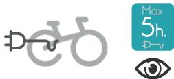
Avoid charging the bike continuously for more than 5 straight hours and always charge your bicycle or battery in a place where you have visual access to it so the charger can be disconnected if any anomaly is detected, such as smoke, strange smells or fire.
Avoid hitting or dropping your battery. If after a fall or an impact the external casing of the battery has been damaged, do not charge or use the battery and contact your authorized dealer for a full diagnosis.
COMPONENTS INSTALLATION
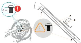
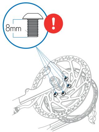
REAR ROTOR FIXING BOLTS
Always use 8mm bolts to fix the rear rotor to the motor hub. The use of longer bolts will damage the motor internal components. The use of shorter bolts will compromise the attachment of the rotor to the motor hub and may cause accidents and serious injuries.
INTERNAL BATTERY AND WATER BOTTLE FIXING BOLTS
Always use the original internal battery fixing bolts to attach the internal battery to the frame and the downtube water bottle. The use of different bolts may damage the battery cells and cause short circuits and/or a fire hazard.
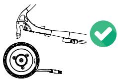
The rear wheel must be installed into the rear dropouts so the motor cable is facing downwards and towards the front of the bike. Installing the wheel in any other orientation may damage the motor cable. Consult the rear wheel tightening torque settings on the axles section of this manual.
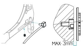
The maximum distance between the PASS sensor and the magnetized cassette lockring is 3mm to allow for a correct reading. If the system is not providing electric assistance, check the position of the PASS sensor and its distance to the lockring.
REPAIRS WITHOUT CHAIN
When carrying out repairs and maintenance for which it was needed to remove the chain, be aware that if the rear wheel is turned, the PASS sensor will detect this movement and the motor will engage and turn the rear wheel. Keep your hands and tools away from the inside of the wheel or any moving parts during repairs or maintenance.
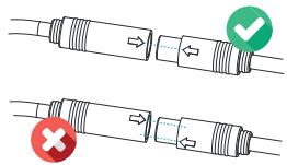
Always connect the cables following the orientation indications on the connectors. Connecting the cables not following the correct orientation may damage the terminals.
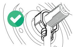
The motor cable protector must always be installed to avoid damage to the motor cable.
Before every use, make sure that the charging point cover is installed correctly to avoid dirt or water ingress into the port.
Do not use metallic tools to clean the charging point of foreing objects or dirt. Pay attention not to damage the terminals during this process.
LIGHTS
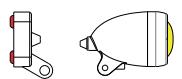
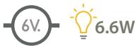
Observe the maximum output specifications when connecting lights to the X35 system. These specifications are: 6V / 6.6W / 1100mA.
Connecting more powerful lights may cause the system to give out an illumination error.
RANGE
The Mahle Ebikemotion X35 system has been designed to offer the maximum possible range for a system of its reduced size and weight. The system offers ranges of up to 125 Km using the internal battery (244.8Wh) and up to 220 Km using both the internal battery and the Range Extender. The final available range, will greatly depend on factor such us:
- Assist level: The use of the more powerful assist levels will decrease the available range.
- Temperature: Charging and using the battery in low temperatures will affect the available range.
· Total weight of cyclist/equipment/luggage.
- Pedal power provided by the cyclist.
- Terrain and climbing: The use on deteriorated roads and routes with considerable altitude gain will affect the available range per charge.
- City use: Frequent stops and accelerations may affect the available range.
ELECTRIC BICYCLE BATTERY TRANSPORT
The transport of the internal Mahle Ebikemotion battery and the external Range Extender battery should be in accordance with the transport rules and regulations of this type of article. The units must always be transported or sent using the original certified packaging and a certified shipping company. Please find information regarding these conditions of transport from your country authority.
If the Range Extender or the internal battery must be sent to Orbea for repair or diagnostics, it must be in the original certified packaging and via a shipping company equipped for battery shipment. Orbea can inform you of the best option.
ELECTRIC BICYCLE TRANSPORT
If you intend to travel with your electric bicycle, research the transport conditions for batteries according to the airline you plan on using to transport your bicycle. The majority of commercial airlines do not permit transport of batteries with a capacity larger than 100 Wh.
To charge the battery, connect the X35 charger to a power outlet and check that the LED on the charger turns green. Connect the X35 charger to the ebike's charging port, aligning the arrows and securing the connection by turning the safety ring clockwise. The LED on the charger will turn red. It will turn green once the battery is fully charged.
While the battery is charging, the Iwoc One light will fade in and out, showing the color code for the current battery level. Once the battery is fully charged, the Iwoc One charging indicator will turn white. Turn the safety ring counterclockwise and detach the charger from the charging port.
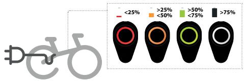
BATTERY LEVEL VISUALIZATION (DURING USE)
While the bike is on, the Iwoc One and Trio will display the current battery level with the following color codes:
· SOLID WHITE: >75% battery charge.
· SOLID GREEN: 75%-50% battery charge.
· SOLID ORANGE: 50%-25% battery charge.
· SOLID RED: <25% battery charge.


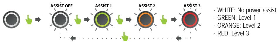
To adjust the power assist level, press the Iwoc One one time. The current power assist level will then blink on screen in the corresponding color code. While still blinking, press the Iwoc One again to adjust the power assist level. The corresponding color codes for the power assist levels are:
flowchart
graph LR
    A["Start"] --> B["ASSIST OFF"]
    B --> C["ASSIST 1"]
    C --> D["ASSIST 2"]
    D --> E["ASSIST 3"]
    style A fill:#999
    style B fill:#ccc
    style C fill:#999
    style D fill:#ccc
    style E fill:#ccc
    note1["• WHITE: No power assist"]
    note2["• GREEN: Level 1"]
    note3["• ORANGE: Level 2"]
    note4["• RED: Level 3"]
TURNING THE LIGHTS ON/OFF
If lights are connected to the X35 system using the Ebikemotion® specific cable and compatible lights, they can be turned on and off as follows:
Press the Iwoc One button once. While it's blinking, press the Iwoc One button again and hold until the LED turns solid yellow. The lights will turn on. Repeat the same procedure to turn the lights off.

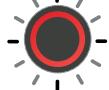
SYSTEM ERRORS
The Iwoc One and Iwoc Trio will indicate an error in the system by displaying a pink light.
SOLID PINK: The system has gone into SAFE mode. Take the ebike to an Orbea dealer to diagnose the problem.
BLINKING PINK: There is an error in the system. Check the User App, which will display the error code, and refer to the User App troubleshooting guide in this manual to fix the error. If the error is not fixed or there is no solution a user can apply, take the ebike to an Orbea dealer to diagnose the problem.
NOTICE
The lights on Gain, both front and rear, are programmed as running lights, so they will turn on automatically when the bicycle is switched on and will turn off when the bicycle is switched off.
Once the bicycle has been turned on, the lights can be switched off using the Iwoc One following the method described above.
However, if the user prefers that the lights do not turn on upon turning on the bicycle, this behaviour can be modified by an Orbea dealer using the Mahle Ebikemotion Dealer App.

07 MAHLE EBIKEMOTION MOBILE USER APP
The MAHLE ebikemotion® User App is a smartphone app that provides an enhanced bike riding experience that is connected to your bicycle. It can be used with conventional bicycles, but when combined with any ebikemotion® bicycle, you will get access to additional information on your ebike and in the User App (when connected to Bluetooth®).
This manual describes the account activation process and main features of the Mahle Ebikemotion user app and its use when connected to an X35 equipped Orbea bicycle. You can access a description of all the app features and functionalities when downloading the complete app user manual from the Mahle Ebikemotion website download center.
www.ebikemotion.com/web/es/centro-de-descargas/
APP INSTALLATION AND REGISTRATION
To install the app, find the Ebikemotion® app in the Apple Store or in iTunes on your iPhone. If you are using an Android phone, the Ebikemotion® app can be found in Google Play.
The User App is identified by a GREEN icon with the letter "e" in white. The user App is free of charge and you can use it for any activity, not necessarily for connecting bikes to the X35 system. It can be used with a non-electric bike, although in order to use all its features, it needs to be linked to an Ebikemotion®- compatible ebike. To successfully complete this installation, you will need a reliable Internet connection.

SMARTPHONE MINIMUM SPECIFICATIONS
· Minimum 512MB RAM (recommended 1 GB).
· 80 MB free space in ROM.
- 1 GHz processor or better (recommended).
- Android 8 or higher - Bluetooth® BLE 4.0.
- Apple iPhone 4S or higher - iOS 7.1.2 / 8 or higher.
- iPhone 5 or 6 updated to the last iOS version (recommended)
- Android phones with 1G of RAM (recommended). 3G connection recommended, but it can also operate offline (some features will be not available).
* Most features operate via Bluetooth®.
Once you have downloaded the app, you will need to register to start using it.
* NOTE: If trying to install, pair, or use the User or Dealer App on an Android phone, the phone's location feature must be turned on. (This is an Android requirement.)
CREATING A NEW ACCOUNT
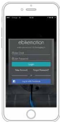
- Click on REGISTER. The app will take to you to a registration form. Complete and submit the form. To help Orbea access your account in the event of future queries about your bike, select the option "I agree to share my account with the bike manufacturers".
- You will receive a confirmation email from MAHLE with a link. Click the link to activate your account.
- MAHLE will confirm that the registration process has been completed.
- Login to the app with your username and password and begin using the app.
* NOTE: If you do not receive a confirmation email, it means there was a problem. Please register again or contact MAHLE.
www.ebikemotion.com/web/contact-2/
REGISTER AND LOGIN WITH EBM
If you have an active ebikemotion® account you will be able to access the app. Enter your username and password and press the green login button. The app will confirm your data and allow access to the app.
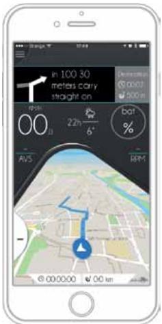
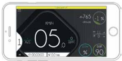
APP DIAGRAM
STATIC COMPONENTS
A Main menu.
B Warning.
C Power assist level.
D Bluetooth ^® connection.
E Time of the active workout.
F Ebike torque (function not active).
G Distance of the active workout.
H Recording status (stop, play, pause).
I Motor power (total power percentage).
J Battery level.
DYNAMIC COMPONENTS
-
Main information component:
-
Speed monitor.
- Map monitor.
-
Range monitor.
-
Auxiliary information component
-
Bike information.
· Health information (if heart rate detected).
- Weather information.
· Music information (if playing).
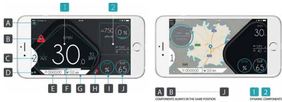
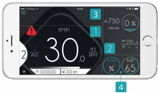
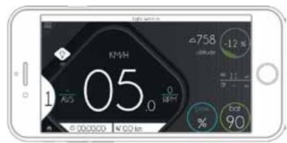
THE APP SCREEN IS DIVIDED INTO FOUR PARTS
- Main monitor.
- Auxiliary components.
- Alerts.
- Ebike power and battery status.
The power is shown as the current percentage used of the maximum available power (250W).
LANGUAGE
The User App will automatically detect what language your smartphone is set to and display the information accordingly as long as the language on your smartphone is supported by the User App. The supported languages are:
- Spanish.
· German.
· French
- English (Default language. If the app doesn't support the configured language of your smartphone, it will automatically be set to English.)
The language cannot be changed in-app.
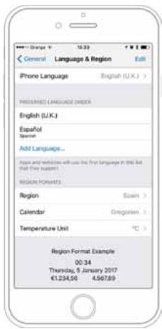
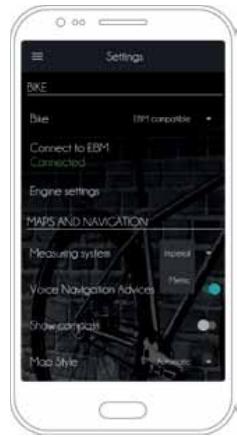
UNITS
The units of measurement (metric or imperial) can be changed from the SETTINGS section of the app menu. Go to MAPS AND NAVIGATION and select your preferred measuring units from the two options available in MEASURING SYSTEM.
PAIRING A BIKE
For a bike to be paired with a smartphone, the User App must be installed and registered:
- Turn the ebike power on.
- Run the User App on your smartphone.
a. iOS: When the app detects an unpaired ebikemotion® compatible ebike, it will automatically pair, and the message "pairing with ebikemotion® bike" will be displayed.
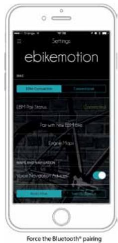
b. Android: Go to SETTINGS in the app menu, then select CONNECT TO EBM to pair with an EBM bike.
To pair the bike with the user app, the option EBM COMPATIBLE must be selected in the SETTINGS menu.
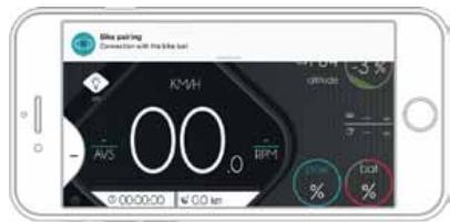
Once the bike is paired, a message will be displayed at the top of the screen informing you that the connection has been established.
The light on the Iwoc One and/or Iwoc Trio remote will turn blue. Your smartphone and ebike will be paired, and no further pairing will be needed.
Once the pairing is complete, the ebike will not be visible to other smartphones.
If the app does not pair with the desired bike, make sure that it has not been paired with another nearby bike.
Turn off the bike being paired and repeat the pairing process.
DISCONNECT THE BLUETOOTH® CONNECTION
You can choose to disconnect the Bluetooth connection without having to turn off the bike.
- ANDROID: Press CONNECT TO EBM in the SETTINGS menu. If the app was connected to a bike, the connection will be disconnected.
- IPHONE: Press PAIR WITH ANOTHER EMB BIKE in the SETTINGS menu. The current connection will be disconnected and the app will automatically search for another available bike.
If no other bike is found, the app will reconnect to the previous bike. If you do not wish for this to occur, turn off the bike.
MAIN FEATURES
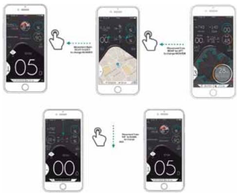
APP CONTROL BY GESTURES
It is possible to change the information displayed in the MONITOR screen using your fingers to swipe on the screen. By doing so, you will be able to change the main monitor view (speed, map, and range) and the auxiliary components.
flowchart
graph TD
    A["Start: 05"] --> B["Step 1: Home Screen Interface with Settings and Time Window"]
    B --> C["Step 2: Home Screen Interface with Settings and Time Window"]
    C --> D["Step 3: Home Screen Interface with Settings and Time Window"]
    D --> E["Step 4: Home Screen Interface with Settings and Time Window"]
    E --> F["End: 05"]
- Changing between speed, maps and range. To change between speed, maps, and range on the MONITOR screen, swipe your finger from right to left on the screen.
- Changing the auxiliary components. To change the auxiliary components on the MONITOR screen, swipe your finger from top to bottom on the screen.
MAIN MONITOR CONTENT
This area of the ebikemotion® app will show you the general information on the main, active screen. There are three different types of information in the main monitor area:
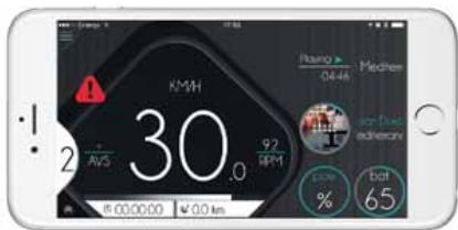
Monitor: Speed View
- SPEED INFORMATION: This monitor shows information about current speed and battery level as a bar graph and a percentage. When the ebikemotion®-compatible ebike is paired, the battery level and power assist level will display a value. The battery bar will show the remaining capacity in green, blue, orange, or red.
- NAVIGATION INFORMATION: The navigation screen shows your position on the map. When you zoom in on the map, the app will remember your zoom level. If NAVIGATION is turned on and a route is planned, the recommended course will be highlighted in blue, your current position will be located in the middle of the screen, and the next route direction will appear at the top of the screen as an alert.
The view in the navigation mode appears in 3D. If you do not have a current route, the view will appear in 2D and your position will appear in the middle of the screen. The map will automatically move and orient to the navigated
course. It is possible to customize the type of map and how it moves in SETTINGS > MAPS AND NAVIGATION. Options that can be modified are: voice navigation advices, show compass, map style, heading mode, and simulate navigation.
The User App does not allow GPX files to be uploaded for route tracking. Point-to-point navigation is permitted through the app.
- RANGE INFORMATION: The range diagram is a special map view that will be appear within an area outlined with a blue circular line representing the estimated destination that you will be able to reach based on average battery usage from the start of activity, the course and the distance that you rode. This area is dynamic and will change automatically. At the same time, you will see the range ring. This ring shows the distance, the amount of time you have ridden, and how much you are able to ride with your average battery use as it relates to your current battery capacity.
The map with the range information will only appear if you have an ebikemotion®-compatible ebike. The range diagram and map area are displayed after the first kilometer is ridden.
APP SETTINGS
Settings displays all the possible configurations and customizable options within the app. To enter this section select SETTINGS in the Main Menu.
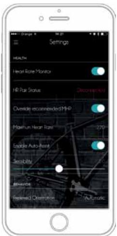
AUTOMATIC HR-BASED POWER ASSIST
This function controls the ebikemotion®-compatible ebike power assist using your heart rate, without the need to change the power assist level on the Iwoc remote. It is possible to activate this function by selecting a maximum heart rate. The app will increase or decrease the power assist of the ebikemotion®-compatible ebike to keep you in your selected exercise zone. (If you activate this option, you will need to establish a desired maximum HR.)
Monitor: Navigation
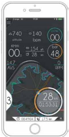
Monitor: Bnge View (Only for eBiles)
Go to MAIN MENU > SETTINGS > HEALTH and select the option ENABLE AUTO-ASSIST. If your HR sensor is connected, the app will automatically change the power assist level, depending on your HR frequency.
SENSIBILITY: This bar lets you control the accuracy response of the power assist level changes based on your HR changes. Low sensibility will take longer to change the power assist level and high sensibility will change it quickly.
The heart rate sensor you wish to connect must be compatible con Bluetooth® 4.0 or later. Heart rate sensors that transmit using the ANT+ protocol are not compatible with this function.
MOTOR MAPS
The User App enables the rider to modify the motor output for each of the three power assist levels. By selecting a level's bar (the WRITE button has to be selected from the top of the screen to modify the levels assistance), the slider at the bottom of the screen can be used to decrease or increase the power assist for that level. The changes for a given level will always range from 0W to the level's fix maximum power output.
Save the changes after modifying the power assist levels by pressing the SAVE button at the top of the screen.
This is how the power output is distributed on each power assist level:
- LEVEL 3: from 0 to 250 W.
- LEVEL 2: from 0 to 175W.
- LEVEL 1: from 0 to 100W.
Settings: HR Monitoring

bar
| Category | Value |
|---|---|
| Done | 20 |
| Save | 65 |
| Other | 90 |
Power Supply Configuration (level by level)
MAP LICENSES FOR EBIKEMOTION® - COMPATIBLE BIKES
In order to enjoy the navigation functionalities of the User App, maps need to be downloaded from the ebikemotion ^® server.
Every ebikemotion ^® bike comes with a five-map subscription. When a new bike is first paired to an User App, the user will be able to download maps from the DOWNLOAD MAPS section of the app menu. Once the first map is downloaded, users have a maximum of three months to download the remaining four maps.
Once the first map has been downloaded, the other four maps will need to be downloaded for the same continent. If you wish to download maps from other continents, you'll need to make an in-app purchase.
Additional maps beyond the subscription can also be downloaded through an in-app purchase.
It is important to note that once a map has been downloaded, it is linked to that app installation. Therefore, if the app is uninstalled or deleted, any downloaded maps will be lost.
Any remaining maps from a subscription that have not been downloaded yet will be available after the app has been reinstalled.
If the maps disappear from your telephone as the result of an app update or for any other reason, contact MAHLE ebikemotion®.
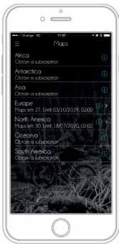
Download Maps: Subscription Status
natural_image
Person riding a bicycle on a highway with green hills in the background (no visible text or symbols)
SYSTEM ALERTS
The app will automatically notify the user about the system's status by displaying alert messages. Normally these alerts refer to the Bluetooth® pairing process, system and operational errors detected on the ebikemotion® -compatible ebike, and general information. The alerts have four priority levels:
- High priority message with permanent alert: Messages will disappear, but the alert icon will be permanently displayed on screen. Press the icon to make the alert emerge again. (Bike error).
- High priority message without permanent alert: High priority message with non-permanent alert: There is no alert icon and the message will disappear (Ebike Bluetooth® pairing, battery low).
- Low priority message with permanent alert: Messages will disappear, but the alert icon will be permanently displayed on screen. (Lights on, walk mode).
- Low priority message without permanent alert: There is no alert icon and the message will disappear (Lights off, HR monitor connection)
High priority message with permanent alert
High priority message with non-permanent alert
Low priority message with permanent alert
Low priority message with non-permanent alert
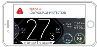
USER APP TROUBLESHOOTING AND ERROR CODES
If you experience an error code message, refer to this table for a troubleshooting guide and corresponding error codes for each problem. If a problem cannot be solved by following this guide, the bike will need to be taken to a dealer for further diagnosis using the Dealer App.
| COD. | DESCRIPTION | CORRECTIVE MEASURE |
| 0 | NO ERROR | No action needed. |
| 1 | THROTTLE ALWAYS ON | Turn off the ebike system. Ensure that the throttle is released and try again. |
| 2 | THROTTLE FAULT | Throttle damaged or out of operation specifications. Contact your ebike dealer. |
| 3 | TORQUE FAULT | Torque damaged or out of operation specifications. Contact your ebike dealer. |
| 4 | LOW VOLTAGE PROTECTION | Battery pack voltage too low. Charge the battery pack. |
| 5 | OVER VOLTAGE PROTECTION | The battery pack voltage is incorrect for this system. Install the correct battery pack for your ebike system. |
| 6 | HALL SENSORS FAULT | Check the motor wire connection. Restart the ebike system. If the problem persists contact your ebike dealer. |
| 7 | OVER TEMPERATURE PROTECTION | The ebike is outside of the permitted temperature range. Turn off the ebike and allow the drive unit to either cool down or heat up to the allowed temperature. Restart the system. If the problem persists, contact your ebike dealer. |
| 8 | TEMPERATURE SENSOR FAULT | Temperature sensor damaged. Contact your ebike dealer. |
| 9 | CURRENT SENSOR FAULT | Current sensor damaged. Contact your ebike dealer. |
| 10 | BMS COMMUNICATION FAULT | Battery pack communication error. Check the battery pack connector. If the problem persists contact your ebike dealer. |
| 11 | COMMUNICATION FAULT LOST FRAME JOB | Remote control communication error. Check the remote connector. If the problem persists, contact your ebike dealer. |
| 12 | DRIVER ERROR: VG UNDERVOLTAGE | Battery pack voltage too low. Charge the battery pack. |
| 13 | DRIVER ERROR OVER TEMPERATURE | The ebike is outside of the permissible temperature range. Turn off the ebike and allow the drive unit to either cool down or heat up to the permissible temperature. Restart the system. If the problem persists, contact your ebike dealer. |
| 14 | DRIVER ERROR OVER CURRENT | Current supplied by the battery pack is too high. Reduce the demand. If the system locks, restart the ebike system. If the problem persists, contact your ebike dealer. |
| 15 | DRIVER ERROR: VDD UNDERVOLTAGE | Battery pack voltage too low. Charge the battery pack. |
| 16 | PHASE I SCG | Check the motor wire connection and restart the ebike system. If the problem persists, contact your ebike dealer. |
| 17 | PHASE II SCG | Check the motor wire connection and restart the ebike system. If the problem persists, contact your ebike dealer. |
| 18 | PHASE III SCG | Check the motor wire connection and restart the ebike system. If the problem persists, contact your ebike dealer. |
| 19 | PHASE I SCS | Check the motor wire connection and restart the ebike system. If the problem persists, contact your ebike dealer. |
| 20 | PHASE II SCS | Check the motor wire connection and restart the ebike system. If the problem persists, contact your ebike dealer. |
| 21 | PHASE III SCS | Check the motor wire connection and restart the ebike system. If the problem persists, contact your ebike dealer. |
| 22 | PHASE I CONNECTION ERROR | Check the motor wire connection and restart the ebike system. If the problem persists, contact your ebike dealer. |
| 23 | PHASE II CONNECTION ERROR | Check the motor wire connection and restart the ebike system. If the problem persists, contact your ebike dealer. |
| 24 | PHASE III CONNECTION ERROR | Check the motor wire connection and restart the ebike system. If the problem persists, contact your ebike dealer. |
| 25 | COMPONENT PROTECTOR | Check the motor wire connection and restart the ebike system. If the problem persists, contact your ebike dealer. |
| COD. | DESCRIPTION | CORRECTIVE MEASURE |
| 26 | NVM ERROR PARAMS TO DEALER | Take the ebike to your dealer to set to the default system parameters. |
| 27 | NVM I ERROR SAVED ERRORS LOST | Error in the error database system. Restart the ebike system.If the problem persists, contact your ebike dealer. |
| 28 | EMN ERROR IMPOSSIBLE SAVE ERRORS | Error database system full. Restart the ebike system. If the problem persists, contact your ebike dealer. |
| 29 | BATTERY VOLTAGE SENSOR FAULT | Battery pack sensor damaged. Restart the ebike system. If the problem persists, contact your ebike dealer. |
| 30 | OVER CURRENT PROTECTION | Current supplied by the battery pack is too high. Reduce the demand.If the system locks, restart the ebike system. If the problem persists, contact your ebike dealer. |
| 31 | PEAK OVER CURRENT PROTECTION | Current supplied by the battery pack is too high. Reduce the demand.If the system locks, restart the ebike system. If the problem persists, contact your ebike dealer. |
| 32 | COMM FATAL ERROR | Fatal error. Restart the ebike system. If the problem persists, contact your ebike dealer. |
| 33 | CURRENT NO SPEED | Locked motor. Check that WALK mode works fine. If the problem persists, contact your ebike dealer. |
| 34 | ACC VOLTAGE ERROR | Power supply problem in the HMI bus. Contact your ebike dealer. |
| 35 | SENSORS 4V3 ERROR | Power supply problem in sensors. Check the wires on the pedaling sensor (PAS sensor) and motor sensor. If the problem persists, contact your ebike dealer. |
| 36 | LIGHTS V ERROR | Power output failure in the lights line. Check the wiring and accessory connected to the light line. If the error persists, disconnect the accessory and check again. If the error is corrected, the accessory exceeds the output specifications. If the error persists, contact the accessory manufacturer. |
CONSULT THE USER APP MANUAL
Download the complete User App manual for a full guide on all features and functions of the ebikemotion® User App at:
www.ebikemotion.com
08 MAHLE EBIKEMOTION WEB DASHBOARD
Once you have created a new account using the User App, you can use the same login details to access the Mahle Ebikemotion web dashboard, where you can access relevant information about your Orbea bicycle, as well as seeing the profiles of your activities recorded using the User App and many other features.
ebikemotion.com/app/login.php

REGISTER AS THE BICYCLE OWNER
To be able to access certain information about your bicycle using the Mahle Ebikemotion web dashboard, it is necessary to register as the bicycle's owner.
The registration process as the owner of an X35 equipped bicycle requires to be the first person that records an activity using the user app while connected to the bicycle.
- Connect your bicycle to the User App.
- Access the app menu and select "Start Activity".
- Record an activity with your bicycle while connected to the app.
- When you have finish the route, select "Finish Activity" from the app menu
- You will receive a message in your linked email account informing you that you are now the owner of the bicycle.
NOTICE
This process is independent from the frame barcode registration on Orbea's website in order to enjoy the benefits of the Orbea's Lifetime Warranty.
Register your bicycle barcode on our web within the first 30 days from the moment of purchase to access the benefits of the extended commercial warranty.
09 MAHLE EBIKEMOTION DEALER MOBILE APP
If you are an authorized Orbea dealer, you will need to download and install on your phone the MAHLE Ebikemotion dealer app to be fully able to diagnose and perform repairs on an X35 equipped Orbea bicycle.
Download and install the user app and create a new account following the method described on previous points. Once you have first logged onto the dealer app and connected to an Orbea bicycle, contact Orbea for us to check your dealer details and activate your access to the dealer app.

10 GEOMETRY AND SIZING
GAIN HYDRO
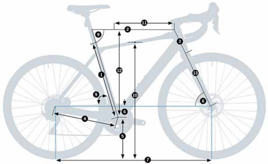
| SIZES | XS | S | M | L | XL |
| 1 - Seat Tube (C-T) | 455 | 485 | 515 | 545 | 575 |
| 2 - Top Tube (EFF) | 507 | 530 | 547 | 571 | 589 |
| 3 - Head Tube | 95 | 120 | 146 | 172 | 196 |
| 4 - Chainstay | 420 | 420 | 420 | 420 | 420 |
| 5 - BB Height | 76 | 76 | 74 | 74 | 74 |
| 6 - BB Drop | 265 | 265 | 267 | 267 | 269 |
| 7 - Wheelbase | 986.14 | 1.000.98 | 1.021.5 | 1.040.6 | 1.048.97 |
| 8 - Head Angle | 71^ | 71.5^ | 72^ | 72^ | 72.5^ |
| 9 - Seat Angle | 75^ | 74.5^ | 74.5^ | 74^ | 74^ |
| 10 - Standover | 708 | 785.73 | 819.5 | 771 | 872.68 |
| 11 - Reach | 366 | 377 | 388 | 399 | 410 |
| 12 - Stack | 525 | 550 | 575 | 600 | 625 |
| 13 - Fork Length | 400 | 400 | 400 | 400 | 400 |
HEIGHT (CM) HEIGHT (IN) SIZE*
| 150-160 | 59.1"-63.0" | XS |
| 160-170 | 63.0"-66.9" | S |
| 170-180 | 66.9"-70.9" | M |
| 180-190 | 70.9"-74.8" | L |
| 190-200 | 74.8"-78.7" | XL |
11 TECHNICAL SPECIFICATIONS
GAIN HYDRO
| MATERIAL |
| Frame | ALUMINUM 6061 |
| Fork | Fork blades: carbonSteerer tube: carbon |
| Recommended use | ALL ROAD EBIKE |
| Available sizes | XS, S, M, L, XL |
| Ebikemotion® remote controller | IWOC ONE |
| Ebikemotion® internal battery fixing | VERTICAL INTO DOWNTUBE |
| Ebikemotion® Range Extender battery fixing | Seat tube |
| Stem | OC COMPONENTSICR headset internal cabling |
| Fork's rake | 50mm |
| Maximum number of headset spacers | 30mm |
| Fork steerer tube | TAPERED 1" 1/8-1" 1/2 |
| Fork lenght (axle-to-crown) | 400mm |
| Headset bearings | UPPER 1" 1/2 (WITH ADAPTER 1 1/2" - 1 1/8" FOR INTERNAL CABLING)LOWER 1" 1/2 |
| Wheel size | 700C |
| Tyre maximum width | 700x40C |
| Tyre maximum external diameter: 702mm |
| Bottom bracket | PRESSFIT (PF86) |
| BB shell width | 86.5mm |
| Fork dropout standard | 12x100mm |
| Front axle measurements | 12x119mm |
| Front axle thread pitch | DOUBLE LEAD "MAVIC SPEED RELEASE" 2P1.0 |
| Front axle thread lenght | 13mm |
| Rear dropout standard | Ebikemotion X35. 135x10mm |
| Rear axle measurements | Ebikemotion X35 motor |
| Rear axle/nuts thread pitch | M121.25mm |
| Seatpost diameter | 27.2mm |
| Seatpost clamp | 31.8mm |
| Front derailleur | DOWN PULL.BRAZE-ON. REMOVABLE MECH HANGER |
| Front derailleur angle | 63° - 66° |
| Big ring max size | 53T |
| Small ring max size | 46T |
| Oval ring max size | 50T |
| Triple chainset compatible | NO |
| Chainline | Shimano 2X Road Groupsets: 43.5mmShimano AllRoad 2X Groupsets: 46.9mmShimano AllRoad 1X Groupsets: 49.7mm |
| Minimum Q-factor | 146mm |
| Maximum crank lenght | 175 |
| Rear derailleur hanger | Standard derailleurs. No direct mount |
| Drivetrain compatibility | Shimano: 10V ROAD / ALL ROAD11V ROAD / ALL ROADDura Ace not compatible |
| Sram: 10V ROAD11V ROAD (No XD o XDR) |
| Only Shimano 10/11S spline cassettesXD/Microspline cassettes not compatible |
| Front brake | DISC. FLAT MOUNT* |
| Min/max front rotor diameter | 160/160mm |
| Rear brake | DISC. FLAT MOUNT* |
| Min/max rear rotor diameter | 160/160mm (with 20mm adaptor) |
| Rear caliper flat mount fixing bolt lenght(Chainstay height = 25mm) | Shimano = 38mmSram = 32mm |
| Cabling | Internal (brakes, gears and x35) through headset, downtube and chainstays |
| Full sleeve |
| Internal front brake routing through fork blade |
| Bottle holder | 2. ALL SIZES |
| Compatible DI2 and EPS | NO |
| Mudguards threads on frame/fork | NO |
| Rack compatible | NO |
| Childseat compatible | NO |
| Trailer compatible | NO |
| Powermeter compatibility** | QUARK: YESSTAGES: YESSRM: YES |
| Lights | Front light integrated in cycle computer mount |
| Rear light integrated in seatpost |
| UCI legal | NO |
* Not all calipers and rotors in the market are compatible with all frames.
All components specified from Orbea have been tested. For aftermarket options, check componentes dimensions and tolerances before purchasing.
** For other powermeters, consult the compatibility and dimensions with the manufacturer.
TECHNICAL SPECIFICATIONS
MAHLE EBIKEMOTION® X35 SYSTEM
MOTOR
| Nominal power | 250W |
| Voltage | 36V |
| Type | TRIPHASIC BRUSHLESS DC |
| Max torque | 40Nm |
| Gear reduction | 14:1 |
| Max speed | 25 Kph (EU) |
| 20 Mph (US) |
| Weight | 2.1Kg (without wheel) |
| Spokes | 32 |
| Compatible cassettes | Up to 11S Shimano standard. XD and Microspline not compatible |
| Compatible frame | 10x135mm DROPOUTS |
INTERNAL BATTERY+CONTROLLER
| Capacity | 244.8Wh |
| Voltage | 36V |
| Weight | 1.5Kg |
| Bluetooth®connectivity | BLUETOOTH 4.1 (FOR MOBILE APPS) |
| ANT+®connectivity | ANT+® LEV (FOR COMPATIBLE COMPUTERS) |
| Lights connections | YES. FRONT AND REAR |
| Maximum light output | 6.6W6V1.100mA |
| Charge level visualization | IWOC ONE / MOBILE APP |
| Charge time | 3.5 h |
| Updates | CAN BUS |
| Diagnosis | CAN BUS / BLUETOOTH® |
CHARGER
| Input | 100-240V / 50-80Hz |
| Output | 42V / 2A |
RANGE EXTENDER (OPTIONAL)
| Capacity | 209.8Wh |
| Voltage | 36V |
| Charge time | 3h |
| Discharge | 1.9A |
| Weight | 1.7 Kg |
| Charge level visualization | IWOC ONE / MOBILE APP |
IWOC ONE REMOTE
| Functions | Assist level change |
| Charge level visualization |
| Error visualization |
| Lights ON/OFF |
| System ON/OFF |
| Assembly | Top tube |
| COMPONENTS WATERPROOFNESS RATING | IP54 |
12 ASSEMBLY AND SPARES HEADSET
HEADTUBE DIMENSIONS

HEADSET SPECIFICATIONS
| TYPE | ID* | OD** | Bearing angle | Compression ring/crown race contact angle | SHIS CODE | Bearing dimensions |
| TOP | 1-1/8" Integrated | 52.1mm | 56mm | 45° | 45° | IS52/42 | Angular contact bearing 42x52x7mm |
| BOTTOM | 1-1/2" Integrated | 52.1mm | 56mm | 45° | 45° | IS52/40 | Angular contact bearing 40x52x7mm |
* ID: Internal headtube diameter.
** OD: External headtube diameter.
HEADSET ASSEMBLY AND SPARES
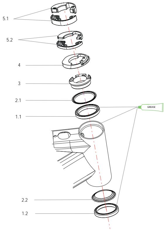
01 HEADSET ICR BEARING KIT
| ART N°: X0430000 | QTY. |
| 1.1 TOP BEARING 1-1/2 INTERN. CABLING | 1 |
| 1.2 BOTTOM BEARING 1-1/2 | 1 |
03 COMPRESSION RING INTERNAL CABLING ROAD
| ART N°: X0450000 | QTY. |
| COMPRESSION RING INTERNAL CABLING ROAD | 1 |
05 HEADSET SPACERS KIT INT CABLING. ROUND
| ART N°: X0780000 | QTY. |
| 5.1 10mm INTERNAL CABLING H/SET SPACER.ROUND | 4 |
| 5.2 5mm INTERNAL CABLING H/SET SPACER. ROUND | 4 |
02 HEADSET DUST SEAL KIT
| ART N°: X0440000 | QTY. |
| 2.1 TOP DUST SEAL H/SET ROAD | 1 |
| 2.2 BOTTOM DUST SEAL H/SET ROAD | 1 |
04 FRAME HEADSET COVER DIAM. 56
| ART N°: X0720000 | QTY. |
| FRAME HEADSET COVER DIAM. 56 | 1 |
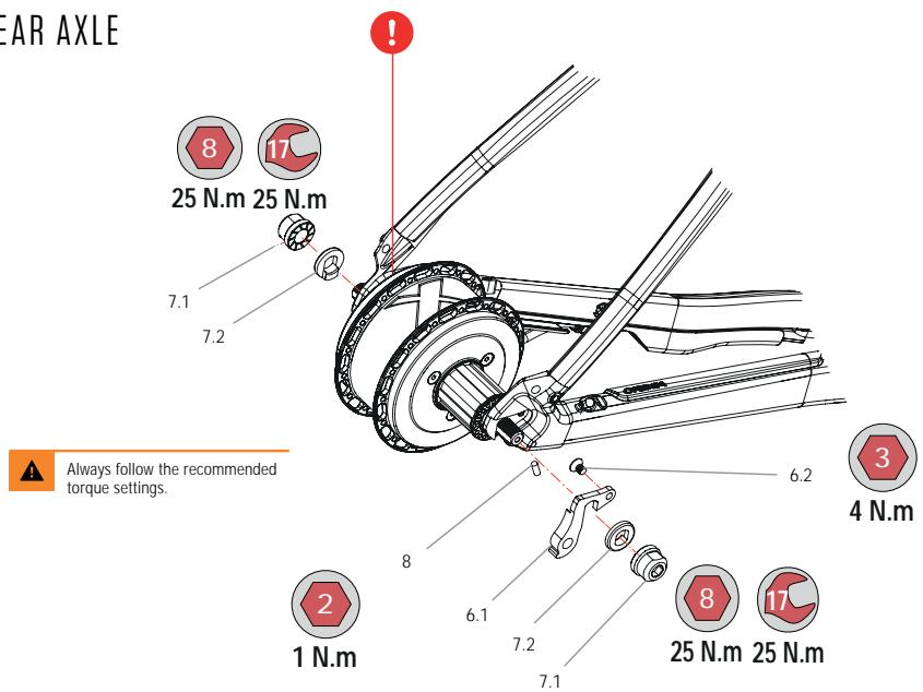
AXLES AND REAR DERAILLEUR
REAR AXLE
FRONT AXLE
06 REAR DERAILLEUR X35 HYDRO
| ART N°: X0970000 | QTY. |
| 6.1 REAR DERAILLEUR X35 HYDRO | 1 |
| 6.2 BOLT M4x8 COUNTERSUNK | 1 |
08 PASS SENSOR GRUBSCREW KIT
| ART N°: X0990000 | QTY. |
| GRUBSCREW M4x10 | 5 |

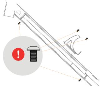
Only use the original 8mm bolts (Y0000113) to attach the rear rotor to the motor hub. The use of longer bolts will damage the motor electronics. The use of shorter bolts will compromise the attachment of the rotor to the hub, potentially causing accidents and serious injuries.
07 X35 MOTOR NUT/WASHER KIT
| ART N°: X0980000 | QTY. |
| 7.1 NUT M12 MOTOR X35 | 2 |
| 7.2 ANTI-TURN WASHER MOTOR X35 | 2 |
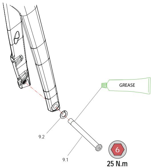
09 THRU-AXLE ROAD 12x119mm
DOUBLE-LEAD THREAD 2P1.0x13mm
| ART N°: X0530000 | QTY. |
 | 9.1 THRU-AXLE ROAD 12x119x2P1.0x13mm | 1 |
| 9.2 AXLE WASHER 12mm | 1 |
NOTICE
The Gain fork is only compatible with Mavic Speed Release thru-axles with a double-lead 2P1.0 thread pitch for faster wheel changes. The use of axles with other thread pitch will damage the frame.
FRAME HARDWARE

Always follow the recommended torque settings.
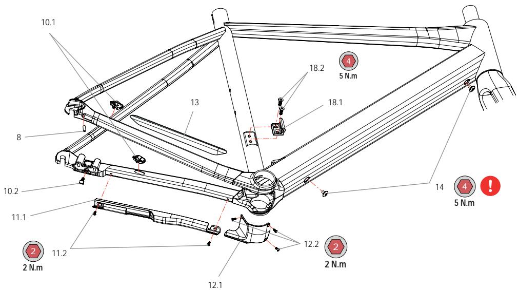
10 CABLEGUIDE KIT VIBE / GAIN H
| ART N°: X1000000 | QTY. |
| 10.1 CABLEGUIDE CLIP BRAKE/DERAILL. | 1 |
| 10.3 THREADED CLIP MOTOR CABLE | 1 |
11 MOTOR CABLE PROTECTOR CHAINSTAY
| ART N°: X1400000 | QTY. |
| 11.1 MOTOR CABLE PROTECTOR CHAINSTAY | 1 |
| 11.2 BOLT M3x8 | 2 |
13 ADHESIVE PROTECTOR RIGHT C/STAY
| ART N°: X1410000 | QTY. |
| ADHESIVE PROTECTOR RIGHT C/STAY | 1 |
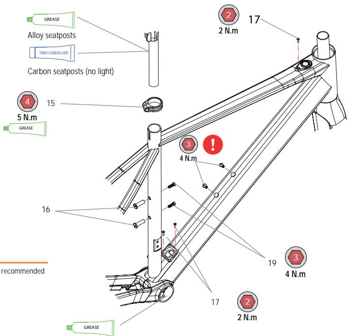
15 SEATPOST CLAMP 31.8 BLK
| ART N°: X0760000 | QTY. |
| SEATPOST CLAMP 31.8 BLK | 1 |
17 BOLT KIT CHARGE POINT / IWOC ONE
| ART N°: X1060000 | QTY. |
| BOLT M3x12 DIN7991 | 4 |

- Always use the Orbea original bolts to fix the internal battery to the downtube.
- Always use bolts of the same length as specificated by Orbea (M5X10) to fix a water bottle cage to the downtube on Gain.
The use of longer bolts may damage the X35 internal battery and cause short circuits and fire hazard.
08 PASS SENSOR GRUBSCREW KIT
| ART N°: X0990000 | QTY. |
| GRUBSCREW M4x10 | 5 |
 | |
12 BB COVER VIBE / GAIN H
| ART N°: X1020000 | QTY. |
 | 12.1 PLASTIC BB COVER | 1 |
| 12.2 BOLT M3x8 | 3 |
14 INTERNAL BATTERY DT FIXING BOLTS
| ART N°: X1040000 | QTY. |
| BATTERY FIXING BOLT M5x8 | 2 |
 | |
16 THREADED INSERTS SEAT TUBE BOTTLE CAGE
| ART N°: X1050000 | QTY. |
| THREADED INSERT M5x25 (PITCH 0.8) | 2 |
 | |
18 FRONT DER. HANGER ROAD 17
| ART N°: X0580000 | QTY. |
| 18.1 FRONT DER. HANGER ROAD 17 | 1 |
| 18.2 COUNTERSUNK BOLT M5x16 | 2 |
NOTICE
19 Always use bolts of the same length specified by Orbea to attach bottle cages and the Range Extender to the frame. Read the Range Extender section of this manual to know the Range Extender assembly compatibility for each frame.
GAIN HYDRO
| SEAT TUBE BOTTLE CAGE BOLTS (WITHOUT RANGE EXTENDER) | M5x12 ISO7380 |
| SEAT TUBE BOTTLE CAGE BOLTS (WITH RANGE EXTENDER) | M5x16 DIN6912 + M5 WASHER |
STEM
OC1 ROAD STEM ASSEMBLIES
OC1 ROAD STEM
(ICR INTERNAL CABLING THROUGH HEADSET)
| MATERIAL | ALUMINUM |
| ∅ FORK | 1" 1/8 |
| ∅ HANDLEBAR | 31.8mm |
| STEERER TUBE CLAIMPING AREA HEIGHT | 38mm |
| FRAME | 60mm |
| Headtube external max ∅ | 58mm |
| Top bearing external ∅ | 52mm |
| INTERNAL CABLING | Up to 2 brake hoses, 2 gear outers and a front light cable (with ICR headset cover and headset spacers) |
| SHIMANO Di2 | External cabling |
| CYCLE COMPUTER ADAPTER | ON FACE PLATE |
| COMPUTER MAXIMUM SIZE: GARMIN 1030 |
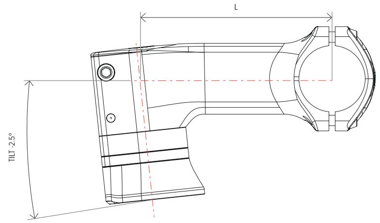
| AVAILABLE LENGTHS (L) | 80, 90, 100, 110, 120 |
| TILT | -2.5° |
| HEADSET SPACERS | 5mm and 10mm. ORBEA ICR INTERNAL CABLING SPECIFIC |
| TOPCAP | ORBEA SPECIFIC |
| WEIGHT | 167 gr (100 mm) |
SPARE PARTS AND ASSEMBLY.
OC1 ROAD STEM
20 HEADSET SPACERS KIT INT CABLING. ROUND
| ART N°: X0780000 | QTY. |
| 20.1 10mm INTERNAL CABLING H/SET SPACER.ROUND | 4 |
| 20.2 5mm INTERNAL CABLING H/SET SPACER.ROUND | 4 |
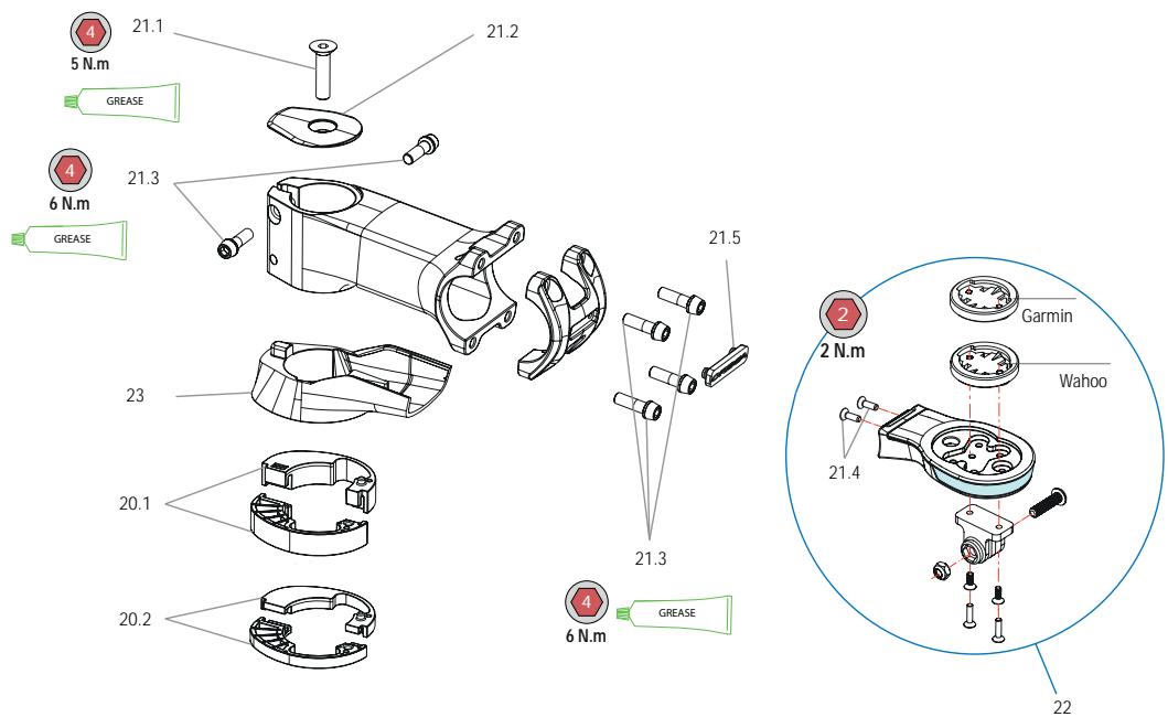
22 OC COMPUTER MOUNT. WITH LIGHT
NOTICE
Consult the lights section of this manual.
21 HARDWARE KIT OC1 ROAD STEM
| ART N°: X0690000 | QTY. |
| 21.1 BOLT M6x35 TOPCAP | 1 |
| 21.2 TOPCAP OC1 ROAD STEM | 1 |
| 21.3 BOLT M5x15 STEERER AND FACEPLATE | 6 |
| 21.4 BOLT M3x10 | 2 |
| 21.5 LOGO ORBEA FACEPLATE | 1 |
23 LOWER OC1 STEM COVER. INTERNAL CABLING. ROUND
| ART N°: X0790000 | QTY. |
| LOWER OC1 STEM COVER. INTERNAL CABLING ROUND 1 |
OC1 ROAD COMPLETE STEMS
HANDLEBARS
Check the geometry and characteristics of the OC road handlebars range on the OC Road Cockpit components manual on the Support section of our website.
natural_image
Technical line drawing of a mechanical linkage or pipe assembly with colored cable routing (no text or symbols)
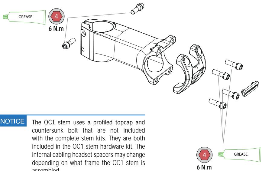
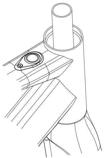
CUTTING THE FORK STEERER TUBE/HEADSET SPACERS
CUTTING THE FORK STEERER TUBE AND HEADSET SPACER INSTALLATION
Due to the front brake hose being internally routed through the fork's blade and steerer tube, removing the fork on Gain requires to disconnect the front brake caliper hose.
However, it is not necessary to disconnect the front caliper to cut the fork's steerer tube to the desired height.
Simply disassemble the OC1 stem from the steerer tube and remove the headset spacers (these can be split in two halves to allow you to remove them without interfering with the cabling).
With the fork completely inserted into the headtube and the bike positioned so the fork is horizontally positioned to avoid debris from falling into the headset, use a steerer tube cutting guide and a carbon or aluminum specific saw (depending on the steerer tube material) to cut the steerer to the desired height. Measure the final height of all components before cutting the steerer.
natural_image
Technical line drawing of a mechanical component with cylindrical and flanged parts (no text or symbols)
When cutting, be careful not to damage any components or cables.
The installation or removal of headset spacers does not require to remove any cables. They are composed of two halves that allow for easy installation without interfering with the cabling

When installing headset spacers (30mm maximum), make sure that the steerer tube is long enough to allow for a correct and safe installation of the stem and that the cables are long enough.

Cutting the fork steerer tube requires advanced mechanical skills and must by performed by a professional bicycle mechanic. Never install headset spacers above the stem. The steerer tube lenght must be set so no spacers are needed above the stem.

When cutting carbon steerer tubes, make sure the safety measures are met to avoid inhaling carbon dust.
13 MAHLE EBIKEMOTION X35 SYSTEM
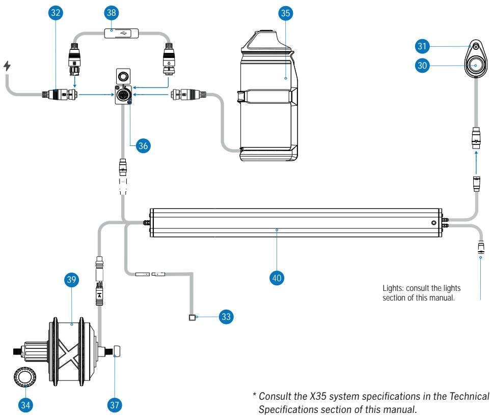
X35 SYSTEM CONNECTION DIAGRAM AND COMPONENTS\*
flowchart
graph TD
    A["1"] --> B["2"]
    B --> C["3"]
    C --> D["4"]
    D --> E["5"]
    E --> F["6"]
    F --> G["7"]
    G --> H["8"]
    H --> I["9"]
    I --> J["10"]
    J --> K["11"]
    K --> L["12"]
    L --> M["13"]
    M --> N["14"]
    N --> O["15"]
    O --> P["16"]
    P --> Q["17"]
    Q --> R["18"]
    R --> S["19"]
    S --> T["20"]
    T --> U["21"]
    U --> V["22"]
    V --> W["23"]
    W --> X["24"]
    X --> Y["25"]
    Y --> Z["26"]
    Z --> AA["27"]
    AA --> AB["28"]
    AB --> AC["29"]
    AC --> AD["30"]
    AD --> AE["31"]
    AE --> AF["32"]
    AF --> AG["33"]
    AG --> AH["34"]
    AH --> AI["35"]
    AI --> AJ["36"]
    AJ --> AK["37"]
    AK --> AL["38"]
    AL --> AM["39"]
    AM --> AN["40"]
    AN --> AO["Lights: consult the lights section of this manual."]
    style A fill:#f9f,stroke:#333
    style B fill:#ccf,stroke:#333
    style C fill:#cfc,stroke:#333
    style D fill:#fcc,stroke:#333
    style E fill:#cff,stroke:#333
    style F fill:#ffc,stroke:#333
    style G fill:#fcf,stroke:#333
    style H fill:#cff,stroke:#333
    style I fill:#cfc,stroke:#333
    style J fill:#fcc,stroke:#333
    style K fill:#ffc,stroke:#333
    style L fill:#cfc,stroke:#333
    style M fill:#fcc,stroke:#333
    style N fill:#cfc,stroke:#333
    style O fill:#fcc,stroke:#333
    style P fill:#cfc,stroke:#333
    style Q fill:#fcc,stroke:#333
    style R fill:#cfc,stroke:#333
    style S fill:#fcc,stroke:#333
    style T fill:#cfc,stroke:#333
    style U fill:#fcc,stroke:#333
    style V fill:#cfc,stroke:#333
    style W fill:#fcc,stroke:#333
    style X fill:#cfc,stroke:#333
    style Y fill:#fcc,stroke:#333
    style Z fill:#cfc,stroke:#333
    style AA fill:#fcc,stroke:#333
    style AB fill:#cfc,stroke:#333
    style AC fill:#fcc,stroke:#333
    style AD fill:#cfc,stroke:#333
    style AE fill:#fcc,stroke:#333
    style AF fill:#cfc,stroke:#333
    style AG fill:#fcc,stroke:#333
    style AH fill:#cfc,stroke:#333
* Consult the X35 system specifications in the Technical Specifications section of this manual.
SPARE PARTS
30 IWOC ONE REMOTE (WITHOUT MOUNTING PLATE)
ROUND CONNECTOR
| ART N°: X1420000 | QTY. |
| IWOC ONE REMOTE (WITHOUT MOUNTING PLATE) ROUND CONNECTOR | 1 |
32 X35 MAHLE CHARGER. 100-240V. 2A EU
| ART N°: X1170000 | QTY. |
| EU | X35 MAHLE CHARGER. 100-240V. 2A | 1 |
| MAINS CABLE EU | 1 |
32 X35 MAHLE CHARGER. 100-240V. 2A UK
| ART N°: X1170200 | QTY. |
| UK | X35 MAHLE CHARGER. 100-240V. 2A | 1 |
| MAINS CABLE UK | 1 |
33 PASS SENSOR X35 B/C MAHLE 63mm
| ART N°: X1210000 | QTY. |
| PASS SENSOR X35 B/C MAHLE 63mm | 1 |
35 RANGE EXTENDER EXTERNAL BATTERY 208Wh MAHLE
| ART N°: Y002 | QTY. |
| 35.1 MAHLE RANGE EXTENDER EXTERNAL BATTERY | 1 |
| 35.2 RANGE EXTENDER MOUNTING CAGE | 1 |
| 35.3 FRAME FIXING BOLTS | 2 |
37 X35 MOTOR CABLE PROTECTOR
| ART N°: X1240000 | QTY. |
| X35 MOTOR CABLE PROTECTOR | 1 |
31 IWOC ONE MOUNTING PLATE. ROUND
| ART N°: X1430000 | QTY. |
| IWOC ONE MOUNTING PLATE. ROUND | 1 |
32 X35 MAHLE CHARGER. 100-240V. 2A US
| ART N°: X1170100 | QTY. |
| US | X35 MAHLE CHARGER. 100-240V. 2A | 1 |
| MAINS CABLE US | 1 |
32 X35 MAHLE CHARGER. 100-240V. 2A AUS
| ART N°: X1170300 | QTY. |
| AU | X35 MAHLE CHARGER. 100-240V. 2A | 1 |
| MAINS CABLE AUS | 1 |
34 MAGNETIZED CASSETTE LOCKRING X35 MAHLE
| ART N°: X1220000 | QTY. |
| MAGNETIZED CASSETTE LOCKRING X35 MAHLE | 1 |
36 INTERNAL BATTERY CHARGING POINT X35 MAHLE C
| ART N°: X1230000 | QTY. |
| INTERNAL BATTERY CHARGING POINT X35 MAHLE C | 1 |
38 UPDATES CABLE USB-GCU
| TOOL AVAILABLE FOR AUTHORIZED ORBEA DEALERS |
39 X35 MOTOR MAHLE 250W 25 KPH
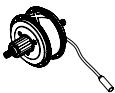
THE X35 MOTOR AND COMPLETE REAR WHEELS ARE ONLY AVAILABLE AS REPLACEMENT ITEMS THROUGH AN AUTHORIZED ORBEA DEALER
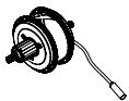
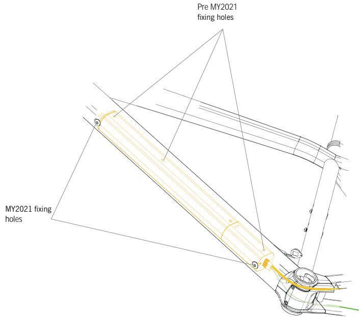
40 X35 INTERNAL BATTERY 244,8WH ANT+ HORIZONTAL AND VERTICAL MOUNTING\*
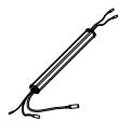
THE X35 INTERNAL BATTERY IS ONLY AVAILABLE AS A REPLACEMENT ITEM THROUGH AN AUTHORIZED ORBEA DEALER
39 X35 MOTOR MAHLE 250W 20 MPH
THE X35 MOTOR AND COMPLETE REAR WHEELS ARE ONLY AVAILABLE AS REPLACEMENT ITEMS THROUGH AN AUTHORIZED ORBEA DEALER
NOTICE
* The X35 internal battery is installed inside the Gain downtube vertically. For that purpose, internal batteries from MY2021 and onwards feature two threaded holes on their side for installation on 2021 Gain frames, besides the three holes on its bottom side for installation on pre2021 Gain frames.
Batteries from MY2021 are compatible with pre2021 Gain, Optima and eMX24 frames. However, pre2021 batteries are not compatible with MY2021 and onwards frames.
RANGE EXTENDER
The Range Extender from Ebikemotion provides an extra 208W/h to the main internal battery on Ebikemotion's X35 systems, increasing the 248W/h of the main battery up to a maximum capacity of as much as 450W/h.
This increase in total capacity of the system will make it possible to increase the autonomy achieved with the internal battery by up to 70%.
The Range Extender works like a portable internal battery charger that charges the main battery while it is turned on. It operates differently from other systems in that on the Ebikemotion X35, only the main battery provides power to the motor, while the Range Extender charges the main battery, regardless of whether the motor demands current from the main battery or not (such as at speeds greater than 25 km/h, when there is no pedaling or the bicycle is not moving).
The Range Extender provides charge to the main battery at a discharge ratio of 2A, while the motor can demand current of up to 9A. Therefore, the Range Extender is not capable of supplying enough current to the motor by itself, and all this current comes from the main battery.
If the main battery is discharged and the Range Extender is connected and turned on, you must wait until the Range Extender has charged the main battery enough for the system to provide electrical assistance. For this reason, it is recommended that whenever you use the Range Extender, always keep the unit connected to the main battery through the charging port in order to make sure that the
main battery charges during use, thus ensuring the maximum possible autonomy. In the case of intensive use of the system in extreme cases, in the top assistance mode during long periods of time, the battery may completely discharge faster than the Range Extender is able to charge it. In this case, you will need to wait for the main battery to have enough charge from the Range Extender to be able to continue riding with electrical assistance.
Acting as the main battery charger, the Range Extender is compatible with any version of the Ebikemotion X35 system.
After connecting the Range Extender to the bicycle charging port, turn on the Range Extender by pressing the Iwoc One button on the top of the unit. The light on the button will turn white. To turn off the Range Extender, press and hold the Iwoc One button for 2-3 seconds.
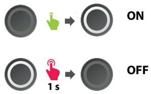
After turning on the Range Extender with the unit connected to the bicycle, the Iwoc One button on the top tube of the bicycle will blink continuously in the color corresponding to the current level of charge of the main battery, just like when the charger is connected to the charging port.
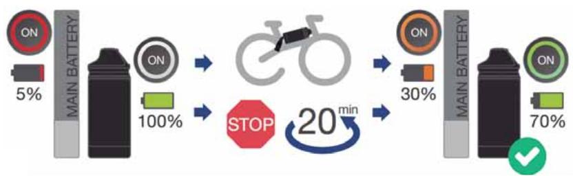
flowchart
graph LR
    A["ON 5%"] --> B["MAIN BATTERY"]
    B --> C["ON 100%"]
    C --> D["STOP 20 min"]
    D --> E["ON 30%"]
    E --> F["MAIN BATTERY"]
    F --> G["ON 70%"]
    G --> H["✓"]
The bicycle will provide assistance as normal and the assistance modes can be changed just as if the Range Extender were not connected.
To ensure maximum continuous autonomy, be sure to turn on the Range Extender as soon as you turn on the bicycle for use, so that the Range Extender begins to charge the main battery from the very beginning.
The Range Extender begins to charge once the internal battery is at 85% of charge or below. If the Range Extender is connected to a fully charged internal battery and the Range Extender is turned on, after a few minutes, when no charge is being provided, it will automatically turn off. When the charge level of the main battery drops below 85%, it will be necessary to turn on the Range Extender by pressing the button to start charging the main battery.
The Range Extender can be charged by itself when it is disconnected from the bicycle. Connect the X35 charger to the charging port on the top of the unit.
The charge levels of the Range Extender will be displayed using the same color code as the main battery:
- WHITE: 100% - 75%
- GREEN: 74% - 50%
- ORANGE: 49% - 25%
- RED: 24% - 1%
<25%
25%
<50%

50%
<75%

75%
The unit can also be charged while it is connected to the main battery. Connect the charger to the charging point of the Range Extender using the Range Extender cable connected to the charging point of the bicycle and both batteries will charge at the same time.
Alternatively, the charging level of the Range Extender can be seen on the Ebikemotion smartphone application. The exact way in which the charge is displayed in the application will depend on the version of the X35 system to which the Range Extender is connected.
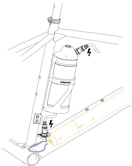
INSTALLING THE RANGE EXTENDER ON GAIN
The Range Extender must be installed on the frame using the Ebikemotion Range Extender cage included with the unit.
The installation of the Range Extender on Gain must always be done on the seat tube, using the threaded inserts on the frame.
For its installation, detach the Range Extender from the holder cage, then install the holder onto the seat tube.
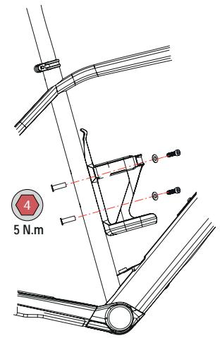
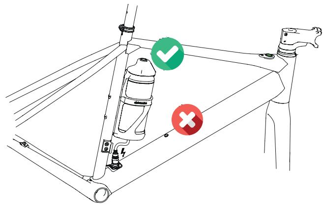
RANGE EXTENDER SPARES
41 RANGE EXTENDER CAGE
| ART N°: X1250000 | QTY. |
| 41.1 RANGE EXTENDER CAGE | 1 |
| 41.2 RANGE EXTENDER SILICON BAND | 1 |
| 41.3 BOLT M5x16 | 2 |
| 41.4 WASHER M5 | 2 |
NOTICE
Always use the M5x16 bolts and washers included with the Range Extender to install it on Gain. The bolts for standard bottle cages included with the frame if your bicycle did not include a Range Extender originally are too short for the weight of the Range Extender.
It is recommended to check the recommended settings regularly to avoid damage to the frame or fixing hardware.
* It is not possible to install and/or connect two Range Extender units on the same system/bicycle.
NOTICE
Read the Lights section of this manual to know about the lights cable routing on Gain Hydro.
NOTICE
Read the X35 system Use Warnings section of this manual to know the correct installation instructions for the rear wheel, cables, PASS sensor and rear rotor.
Always follow the recommended torque settings for all the components on your bicycle.

The removal and installation of the X35 system components may require to remove and install several mayor components of the bicycle, such as the fork, the chainset and bottom bracket, and may therefore be beyond the mechanical knowledge of most users. Always take your bicycle to an authorized Orbea dealer for the installation and replacement of these components.
The incorrect installation of the bicycle components may be cause of accidents and serious injuries, as well as cause damage to the components that may not be covered by the warranty.

Always take the necessary precautions when working with electric components to avoid electric shocks and damage to the components.
Connect all components in the correct way to avoid short circuits and exposure to elements.
Cover any crimped cable connections (if there were any) with heat shrink tubing or electrical tape to avoid short circuits.
REPLACING THE IWOC ONE AND PASS SENSOR
It is not necessary to remove the fork to replace the Iwoc One on Gain. Remove the Iwoc One from the top tube and carefully pull from the cable until you can access the connector to the battery cable.
Connect a new Iwoc One, introduce the connector and excess cable into the top tube and fix the Iwoc One plate onto the top tube, always following the recommended torque settings in this manual.
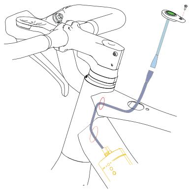
natural_image
Technical line drawing of a mechanical assembly with no visible text or symbols
The PASS sensor can also be replaced without removing any other component from the bicycle (besides the rear wheel).
Remove the rear wheel from the frame. Remove the bottom bracket cover from the frame and locate the PASS sensor cable connector to the battery cable. Disconnect the PASS sensor cable. Loosen the PASS sensor grubscrew on the right dropout, carefully pull from the PASS sensor cable from the rear dropout until the PASS sensor cable is completely out of the right chainstay.
Follow the opposite process to install a new PASS sensor. Make sure that the distance between the PASS sensor once it is installed in its housing and the magnetized cassette lockring is 3mm maximum. Install the BB cover and install the rear wheel on the frame making all connections and following the recommended torque settings as shown in this manual.
LIGHTS CABLE INSTALLATION
The installation and replacement of the lights cable requires the removal of the internal battery and must be performed by an Authorized Orbea dealer.
Read the Lights section of this manual to know about the lights cable routing on Gain.
REPLACING THE X35 INTERNAL BATTERY
Replacing the X35 internal battery is a process that requires advanced mechanical knowledge for its correct installation.
The bicycle fork, chainset and bottom bracket need to be removed and all the pedelec system components disconnected.
Replacing the X35 internal battery is a process that must be performed by an authorized Orbea dealer.
The X35 internal battery on your Orbea bicycle carries all the relevant information about your bike, such as the serial number and the specific motor maps for your model.
If the internal battery needs to be replaced due to natural wear or a warranty claim, contact your authorized Orbea dealer, who will provide Orbea with your bicycle information and carry out the claim and installation.
NOTICE
The X35 internal battery is installed inside the Gain downtube vertically. For that purpose, internal batteries from MY2021 and onwards feature two threaded holes on their side for installation on 2021 Gain frames, besides the three holes on its bottom side for installation on pre2021 Gain frames.
Batteries from MY2021 are compatible with pre2021 Gain, Optima and eMX24 frames. However, pre2021 batteries are not compatible with MY2021 and onwards frames.
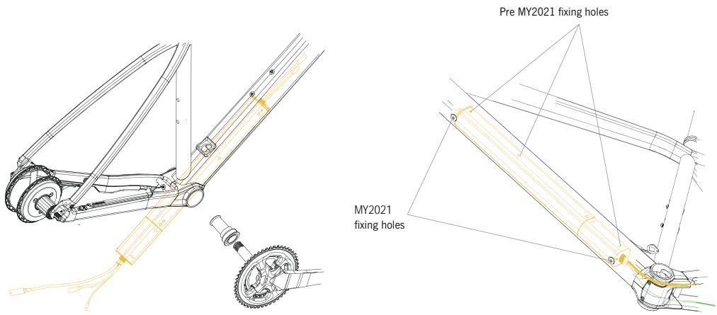
MAHLE EBIKEMOTION X35 SYSTEM ANT+ CONNECTIVITY
From Model Year 2020, all Orbea ebikes equipped with a MAHLE Ebikemotion® X35 system do have ANT+ connectivity from the factory, which allows for the visualization of the X35 system data on compatible head units, such as the OC ANT+ LEV display, amongst other units in the market.
The X35 system uses the ANT+ protocol to communicate to compatible head units real-time data of the system. The ANT+ communication occurs from the internal battery to the head unit, it is not possible to control the system using ANT+ accessories. The protocol by which certain accessories can change parameters of the system, such as the Mahle Ebikemotion mobile apps or a heart rate monitor, must be Bluetooth 4.0 or later versions.
COMPATIBLE HEAD UNITS
The X35 system uses the ANT+ LEV protocol.
The head unit to be connected to the X35 system for the display of the system data must be compatible with this data transmission protocol. Not all ANT+ units on the market are necessarily compatible with the LEV protocol.
The OC ANT+ LEV display unit is fully compatible with the ANT+ LEV protocol and allows for the visualization of the following X35 system data:
- Current speed.
- Internal X35 battery charge level.
- Total system odometry.
- Current assist level.
- System errors.
The OC ANT+ LEV display unit also allows for the assist levels to be changed from the unit itself.
Consult all the OC ANT+ LEV functions on the specific user manual from our website.
NOTICE
The system data and the specific functions available on other ANT+ LEV units in the market will depend on the characteristics of the connected head unit.
Consult with the compatible head unit manufacturer.
You can access the list of ANT+ LEV compatible head units here:
www.thisisant.com/directory
Select the option LEV Display in the Profiles section for a complete list of the compatible devices.
X35 ERRORS DISPLAY:
Through the ANT+ LEV connection, errors on the MAHLE Ebikemotion® X35 system can be displayed on the compatible head units. If the system has recovered from a previous error, this can also be displayed in the head unit.
- ERRORS IN THE X35 SYSTEM: If there is an error code in the system, this will be shown in the head unit by the generic error code E255. All system error codes (regardless of the specific error code in the system) will be shown by the code E255 in the head unit. Connect the X35 system to the MAHLE Ebikemotion® X35 mobile apps (User or Dealer app) to access the system's specific error code and the diagnostics/repair method.
- ERROR RECOVERY VISUALIZATION: If the system has recovered from an error, this will be shown in the compatible head unit by the generic code E000 when the system is switched on and paired with the display. The E000 code will disappear after a few seconds. The system has no errors.
14 LIGHTS
LIGHTS SPECIFICATIONS
NOTICE
Observe the maximum output specifications for the system when connecting lights to the X35 system. Connecting lights of greater output may make the system to give out an illumination error.
MAXIMUM LIGHTS SPECIFICATIONS:
| FRONT LIGHT |
| ORBEA OC. INTEGRATED ON COMPUTER MOUNT | Luminosity: 60 lumen |
| Input voltage 6-12V DC |
| On/Off: Iwoc One |
| Connection: Mahle lights cable (bare cable) |
| REAR LIGHT |
| LEZYNE REAR STVZO EBIKE INTEGRATED IN SEATPOST | Luminosity: 30 lumen / 11 lux |
| Output: 1.25W |
| Input voltage: 6-12V DC |
| 2 LED |
| Cable lenght: 135 cm |
| On/Off: Iwoc One |
| Connection: Mahle lights cable (JST connector) |
NOTICE
The lights on Gain, both front and rear, are programmed as running lights, so they will turn on automatically when the bicycle is switched on and will turn off when the bicycle is switched off. Once the bicycle has been turned on, the lights can be switched off using the Iwoc One following the method described in the X35 operation section of this manual. However, if the user prefers the lights not to turn on upon turning on the bicycle, this behaviour can be modified by an Orbea dealer using the Mahle Ebikemotion Dealer App.
COMPONENTS DIAGRAM
43 OC COMPUTER MOUNT. INTEGRATED LIGHT. 6V
| ART N°: X1490000 | QTY. |
| COMPUTER MOUNT. INTEG. LIGHT | 1 |
| GARMIN/WAHOO ADAPTER | 1 |
| CAMERA BRACKET | 1 |
| FACEPLATE M3x10 FIXING BOLT | 1 |
45 RUBBER PLUG 27.2 LIGHT CABLE GUIDE
| ART N°: X1280000 | QTY. |
| RUBBER PLUG 27.2 LIGHT CABLE GUIDE | 1 |
|
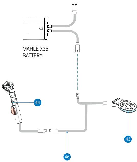
44 GAIN SEATPOST 27.2 350mm + LEZYNE REAR STVZO LIGHT
| ART N°: X1273500 | QTY. |
| GAIN SEATPOST 27.2 350mm + LEZYNE REAR STVZO LIGHT | 1 |
46 MAHLE X35 LIGHTS CABLE. 2 LIGHTS BARE CABLE (F) + JST CONNECTOR (R)
| ART N°: X1320000 | QTY. |
| MAHLE X35 LIGHTS CABLE. 2 LIGHTS BARE CABLE (F) + JST CONNECTOR (R) | 1 |
NOTICE
The installation and replacement of lights or the lights cable on Gain may require the removal and assembly of several key components of the bicycle, such as the fork, the chainset and/or the internal battery, and are therefore beyond the mechanical knowledge of must users. Always take your Orbea bicycle to an authorized Orbea dealer for the installation or replacement of these components.
#
Always take the necessary precautions when working with electric components to avoid electric shocks and damage to the components.
Connect all components in the correct way to avoid short circuits and exposure to elements.
Cover any crimped cable connections (if there were any) with heat shrink tubing or electrical tape to avoid short circuits.
LIGHTS CABLE ROUTING
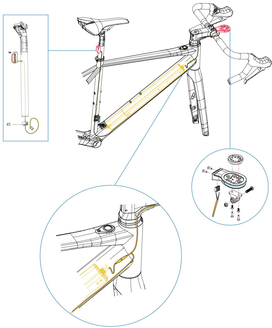
ORBEA

El fabricante / The manufacturer:
Orbea S. Coop
Polígono Industrial Goitondo s/n
48269, Mallabia (Bizkaia) - Spain
EMX 24, GAIN, KATU, KERAM, OPTIMA, VIBE
and WILD
- Directiva 2006/42/CE / Directive 2006/42/EC
- Directiva 2004/108/CE / Directive 2004/108/EC
- Directiva 2011/65/CE / Directive 2011/65/EC
Las siguientes normas armonizadas han sido completamente aplicadas / The following harmonized standards have been fully applied:
De acuerdo con la Directiva 2006/42/CE / According to Directive 2006/42/EC - EN 12100
De acuerdo con la Directiva 2004/108/CE / According to Directive 2004/108/EC
- EN 61000-3-2
- EN 61000-3-3
- EN 61000-6-1
- EN 61000-6-3
- 61000-4-2
ORBEA participates actively on facebook and Twitter with our fantastic global community of riders. Looking to find spots to ride or plan a vacation? Someone will have the answers:
FACEBOOK
www.facebook.com/OrbeaBicycles
www.twitter.com/Orbea/
YOUTUBE
Visit our Orbea Channel on YouTube for a variety of helpful setup and tech videos:
www.youtube.com/user/OrbeaBicycles
INSTAGRAM
www.instagram.com/orbeabicycles
ORBEA CONTENT
View and download photos, videos and documents.
content.orbea.com/us-en/
BLOG ORBEA
Our dealers are experts and should be able to assist you with setting up and maintaining your Orbea bicycle. A complete listing of Orbea dealers and distributors can be located on our website:
www.orbea.com/us-en/dealers/?country=INT
Access Orbea's contact details and form at:
05 ADVERTENCIAS DE USO DEL SISTEMA MAHLE EBIKEMOTION X35
www.ebikemotion.com/web/contact-2/
UNIDADES DE MEDIDA
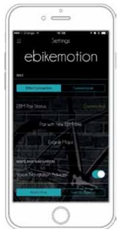
Force the Bluetooth® pairing
EMPAREJAR UNA BICICLETA
flowchart
graph TD
    A["05"] --> B["User Interface: Weather Monitoring & Navigation"]
    B --> C["00"]
    C --> D["User Interface: Weather Monitoring & Navigation"]
    D --> E["05"]
    E --> F["User Interface: Weather Monitoring & Navigation"]
Monitor: Navigation
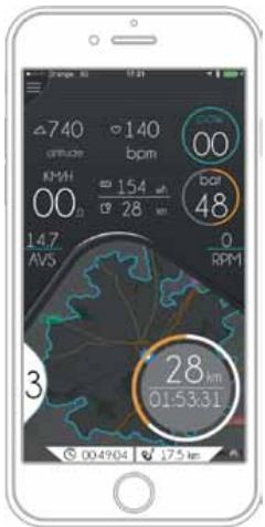
Monitor: Bnge View (Only for eBills)
Settings: HR Monitoring
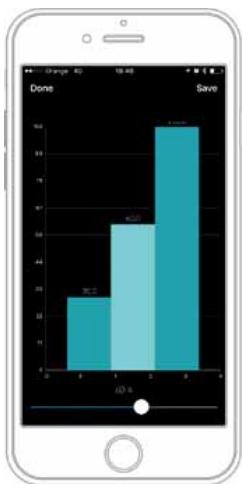
bar
| Category | Value |
|---|---|
| Done | 20 |
| Save | 65 |
| Other | 90 |
Power Supply Configuration (level by level)
LICENCIAS DE MAPAS PARA BICICLETAS COMPATIBLES CON EBIKEMOTION®
Download Maps: Subscription Status

natural_image
Person riding a bicycle on a highway with green hills in the background (no visible text or symbols)
ALERTAS DEL SISTEMA
High priority message with permanent alert

High priority message with non-permanent alert

Low priority message with permanent alert

Low priority message with non-permanent alert
ebikemotion.com/app/login.php

REGISTRO COMO PROPIETARIO DE TU BICICLETA CON SISTEMA MAHLE EBIKEMOTION
| TALLA | XS | S | M | L | XL |
| 1 - Tubo de sillín (C-T) | 455 | 485 | 515 | 545 | 575 |
| 2 - Tubo horizontal (EFF) | 507 | 530 | 547 | 571 | 589 |
| 3 - Tubo frontal | 95 | 120 | 146 | 172 | 196 |
| 4 - Vaina | 420 | 420 | 420 | 420 | 420 |
| 5 - Altura eje pedalier | 76 | 76 | 74 | 74 | 74 |
| 6 - Caída eje pedalier | 265 | 265 | 267 | 267 | 269 |
| 7 - Distancia entre ejes | 986.14 | 1.000.98 | 1.021.5 | 1.040.6 | 1.048.97 |
| 8 - Ángulo frontal | 71^ | 71.5^ | 72^ | 72^ | 72.5^ |
| 9 - Ángulo del sillín | 75^ | 74.5^ | 74.5^ | 74^ | 74^ |
| 10 - Altura base | 708 | 785.73 | 819.5 | 771 | 872.68 |
| 11 - Largo del cuadro | 366 | 377 | 388 | 399 | 410 |
| 12 - Altura del cuadro | 525 | 550 | 575 | 600 | 625 |
| 13 - Longitud horquilla | 400 | 400 | 400 | 400 | 400 |
ALTURA (CM)
ALTURA (IN)
TALLA*
| 150-160 | 59.1"-63.0" | XS |
| 160-170 | 63.0"-66.9" | S |
| 170-180 | 66.9"-70.9" | M |
| 180-190 | 70.9"-74.8" | L |
| 190-200 | 74.8"-78.7" | XL |
POTENCIA
MONTAJES CON POTENCIA OC1
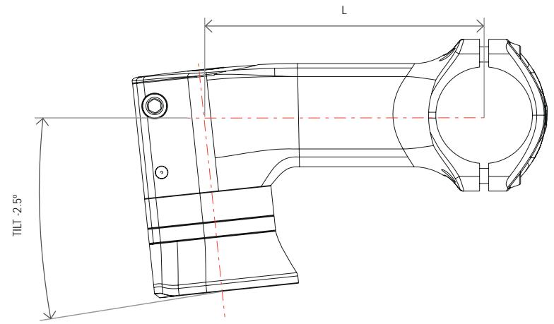
POTENCIA OC1 ROAD
natural_image
Technical line drawing of a mechanical linkage or pipe assembly with colored cable routing (no text or symbols)
natural_image
Technical line drawing of a mechanical component with cylindrical and base components (no text or symbols)
BLANCO: 100% - 75%
VERDE: 74% - 50%
NARANJA: 49% - 25%
ROJO: 24% - 1%
<25%

25%
<50%

50%
<75%

75%
MONTAJE DEL RANGE EXTENDER EN GAIN
RECAMBIOS RANGE EXTENDER
41 PORTABIDÓN RANGE EXTENDER
| ART N°: X1250000 | CANT. |
| 41.1 PORTABIDÓN RANGE EXTENDER MAHLE | 1 |
| 41.2 BANDA SOLICONA RANGE EXTENDER | 1 |
| 41.3 TORNILLO M5x16 | 2 |
| 41.4 ARANDELA M5 | 2 |
AVISO
natural_image
Technical line drawing of a mechanical assembly with no visible text or symbols
www.thisisant.com/directory
El fabricante / The manufacturer:
Orbea S. Coop
Polígono Industrial Goitondo s/n
48269, Mallabia (Bizkaia) - Spain
EMX 24, GAIN, KATU, KERAM, OPTIMA, VIBE
and WILD
- Directiva 2006/42/CE / Directive 2006/42/EC
- Directiva 2004/108/CE / Directive 2004/108/EC
- Directiva 2011/65/CE / Directive 2011/65/EC
Las siguientes normas armonizadas han sido completamente aplicadas / The following harmonized standards have been fully applied:
De acuerdo con la Directiva 2006/42/CE / According to Directive 2006/42/EC - EN 12100
De acuerdo con la Directiva 2004/108/CE / According to Directive 2004/108/EC
- EN 61000-3-2
- EN 61000-3-3
- EN 61000-6-1
- EN 61000-6-3
- 61000-4-2
www.twitter.com/Orbea/
YOUTUBE
www.youtube.com/user/OrbeaBicycles
INSTAGRAM
www.instagram.com/orbeabicycles
ORBEA CONTENT