
FMA 905 WH XS - Kitchen hood FRANKE - Free user manual and instructions
Find the device manual for free FMA 905 WH XS FRANKE in PDF.
| Product Type | Kitchen Hood |
| Brand | FRANKE |
| Model | FMA 905 WH XS |
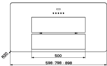
| Width | 900 mm |
| Depth | 500 mm |
| Height | 250 mm |
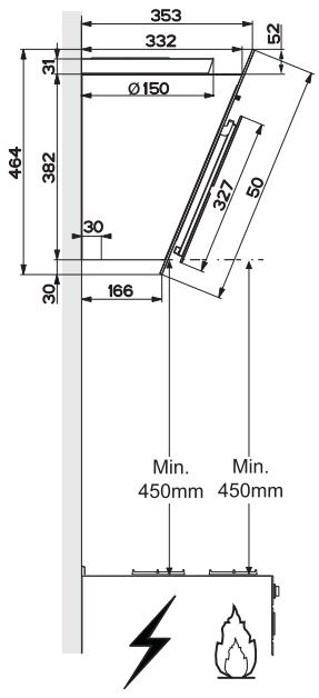
| Minimum distance from cooking surface | 650 mm |
| Power supply | 220-240 V ~ 50 Hz |
| Motor power | 200 W |
| Control type | Tactile |
| Number of speeds | 3 + timed boost (6 min) |
| Lighting | LED 7 W, class 1M |
| Grease filters | Self-supporting metal, dishwasher safe (every 2 months) |
| Activated carbon filter | Replace every 4 months (not washable) |
| Material | White lacquered steel |
| Net weight | 15 kg |
| Airflow | 650 m³/h |
| Noise level | 50 dB(A) |
| Repairability | LED lighting replaceable only by after-sales service |
| Installation | Wall-mounted, extractor or recirculation |
| Safety | Mandatory bipolar switch, grounding |
Frequently Asked Questions - FMA 905 WH XS FRANKE
User questions about FMA 905 WH XS FRANKE
0 question about this device. Answer the ones you know or ask your own.
Ask a new question about this device
Download the instructions for your Kitchen hood in PDF format for free! Find your manual FMA 905 WH XS - FRANKE and take your electronic device back in hand. On this page are published all the documents necessary for the use of your device. FMA 905 WH XS by FRANKE.
USER MANUAL FMA 905 WH XS FRANKE
The Instructions for Use apply to several versions of this appliance. Accordingly, you may find descriptions of individual features that do not apply to your specific appliance.
INSTALLATION
- The manufacturer will not be held liable for any damages resulting from incorrect or improper installation.
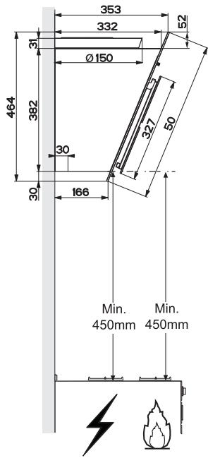
- The minimum safety distance between the cooker top and the extractor hood is 650~mm (some models can be installed at a lower height, please refer to the paragraphs on working dimensions and installation).
- Check that the mains voltage corresponds to that indicated on the rating plate fixed to the inside of the hood.
- For Class I appliances, check that the domestic power supply guarantees adequate earthing.
Connect the extractor to the exhaust flue through a pipe of minimum diameter 120mm . The route of the flue must be as short as possible.
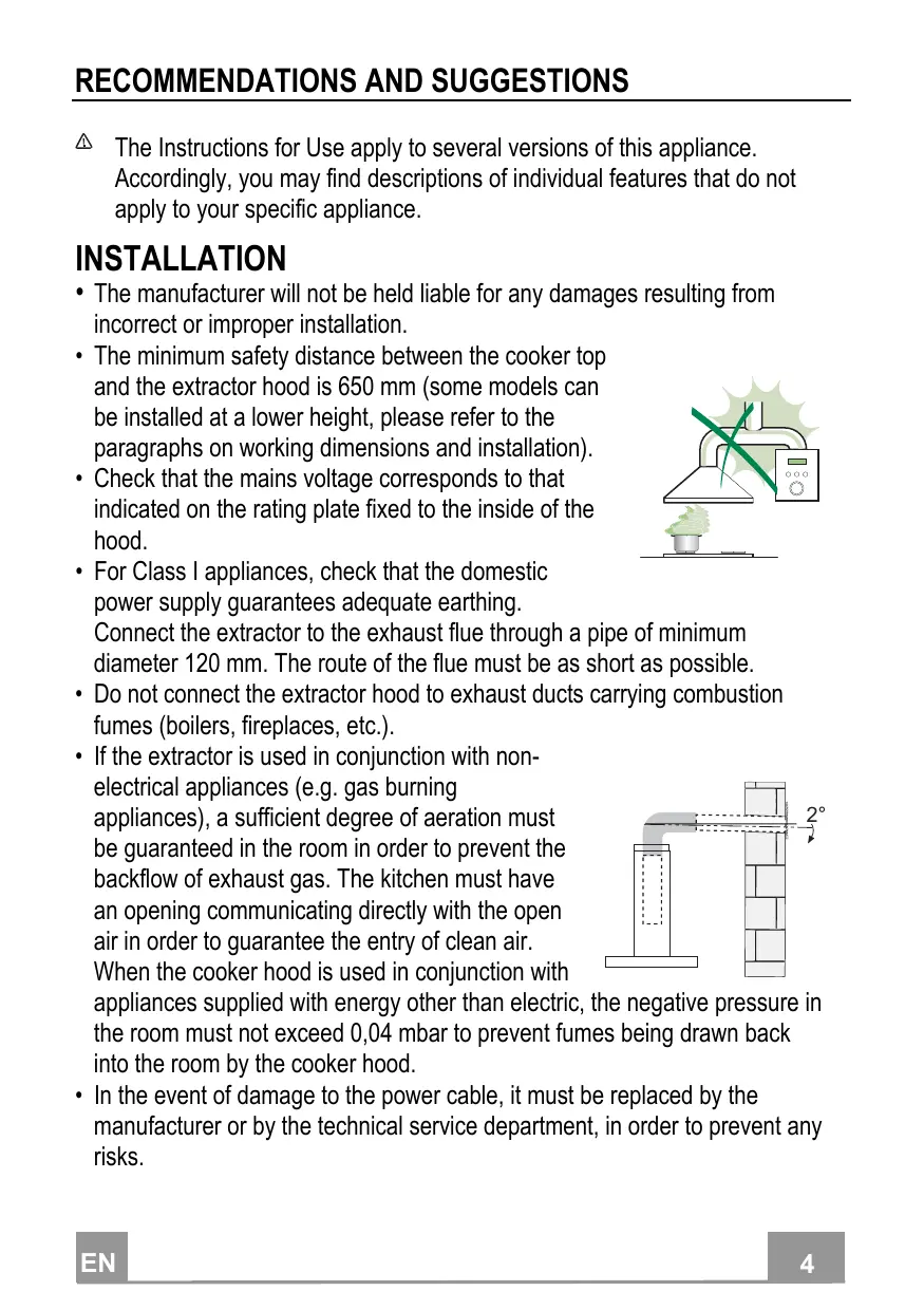
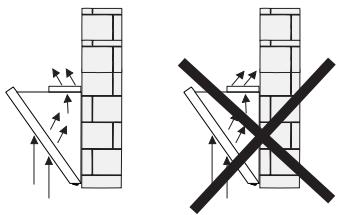
- Do not connect the extractor hood to exhaust ducts carrying combustion fumes (boilers, fireplaces, etc.).
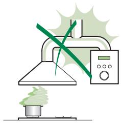
- If the extractor is used in conjunction with nonelectrical appliances (e.g. gas burning appliances), a sufficient degree of aeration must be guaranteed in the room in order to prevent the backflow of exhaust gas. The kitchen must have an opening communicating directly with the open air in order to guarantee the entry of clean air. When the cooker hood is used in conjunction with
appliances supplied with energy other than electric, the negative pressure in the room must not exceed 0.04 mbar to prevent fumes being drawn back into the room by the cooker hood.
- In the event of damage to the power cable, it must be replaced by the manufacturer or by the technical service department, in order to prevent any risks.
- If the instructions for installation for the gas hob specify a greater distance specified above, this has to be taken into account. Regulations concerning the discharge of air have to be fulfilled.
- Use only screws and small parts in support of the hood.
Warning: Failure to install the screws or fixing device in accordance with these instructions may result in electrical hazards.
- Connect the hood to the mains through a two-pole switch having a contact gap of at least 3mm .
USE
- The extractor hood has been designed exclusively for domestic use to eliminate kitchen smells.
- Never use the hood for purposes other than for which it has been designed.
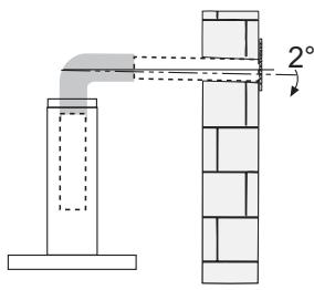
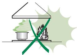
- Never leave high naked flames under the hood when it is in operation.
- Adjust the flame intensity to direct it onto the bottom of the pan only, making sure that it does not engulf the sides.
- Deep fat fryers must be continuously monitored during use: overheated oil can burst into flames.
- Do not flambé under the range hood; risk of fire.
- This appliance can be used by children aged from 8 years and above and persons with reduced physical, sensory or mental capabilities or lack of
experience and knowledge if they have been given supervision or instruction concerning use of the appliance in a safe way and understand the hazards involved. Children shall not play with the appliance. Cleaning and user maintenance shall not be made by children without supervision.
- “CAUTION: Accessible parts may become hot when used with cooking appliances.”
MAINTENANCE
- Switch off or unplug the appliance from the mains supply before carrying out any maintenance work.
- Clean and/or replace the Filters after the specified time period (Fire hazard).
- The Grease filters must be cleaned every 2 months of operation, or more frequently for particularly heavy usage, and can be washed in a dishwasher.
- The Activated charcoal filter is not washable and cannot be regenerated, and must be replaced approximately every 4 months of operation, or more frequently for particularly heavy usage.
- Clean the hood using a damp cloth and a neutral liquid detergent.
The symbol on the product or on its packaging indicates that this product may not be treated as household waste. Instead it shall be handed over to the applicable collection point for the recycling of electrical and electronic equipment. By ensuring this product is disposed of correctly, you will help prevent potential negative consequences for the environment and human health, which could otherwise be caused by inappropriate waste handling of this product. For more detailed information about recycling of this product, please contact your local city office, your household waste disposal service or the shop where you purchased the product.
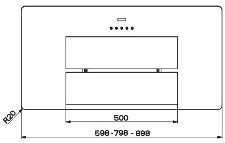
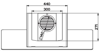
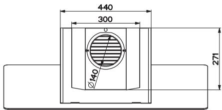
Dimensions
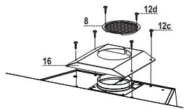
Components
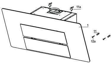
| Ref. | Q.ty | Product Components |
| 1 | 1 | Hood Body, complete with: Controls, Light, Blower, Filters |
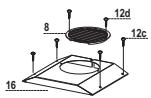
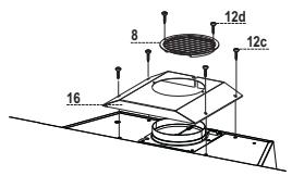
| 8 | 1 | Directional Air Outlet grille |
| 16 | 1 | Filter cover |
| Ref. | Q.ty | Installation Components |
| 11 | 2 | Wall Plugs |
| 11a | 2 | Wall Plugs SB 12/10 |
| 12a | 2 | Screws 4,2 x 44,4 |
| 12c | 4 | Screws 2,9 x 6,5 |
| 12d | 2 | Screws 2,9 x 9,5 |
| Q.ty | Documentation | |
| 1 | Instruction Manual |
Wall drilling and bracket fixing
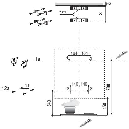
As a first step, proceed with the following drawings:
- a vertical line up to the ceiling or up to the upper limit, at the centre of the area in which the hood is to be fitted;
- a horizontal line at a minimum 788mm above the cooker top.
- Mark a point (1) on the horizontal line, 164 mm to the right of the vertical reference line.
- Repeat this operation on the other side, checking that the two marks are levelled.
- Mark a reference point (2) as indicated at 140mm from the vertical reference line and 540 mm above the cooker top.
- Repeat this operation on the other side, checking that the two marks are levelled.
- Drill at the marked points (1), using a 12mm drill bit.
- Drill at the marked points (2) using a 8 mm drill bit.
- Insert the bracket plugs 11a into the holes (1) and tighten the screws.
- Insert plug 11 into holes (2).
To install a decorative chimney ( optional )
- Place bracket 7.2.1 on the wall, about 1 - 2mm from the ceiling or from the upper limit, aligning the centre (notch) with the vertical reference line.
- Mark the wall at the centres of the bracket holes.
- Place the bracket 7.2.1 on the wall at X mm below the first bracket ( X = height of the upper chimney section), aligning the centre (notch) with the vertical line.
- Mark the wall at the centres of the bracket holes.
- Drill 8 mm holes at all the marked centre points.
- Insert the wall plugs 11 in the holes.
Fix the brackets using the 12a screws (4,2× 44,4) supplied with the hood.
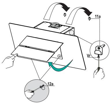
Fitting the hood body
- Open the doors/the door (See section Open Panels).
- Remove the Metal grease filters using the handles provided.
- Adjust the two screws Vr , in the brackets 11a, so that they are at the start of their travel.
- Hook the hood body to the two brackets 11a.
- From the inside of the hood body, turn screws Vr to level the hood body itself.
- Fasten the safety screw 12a.
- Close the doors/the door again.

Air outlet - Recirculation Version
- Screw the filter cover onto the air outlet, using four screws 12c (2.9 x 6.5).
Fix the directional Grid 8 on the recycled air outlet, using 2 screws 12d (2.9 x 9.5) provided. - Open the Door/Doors (See paragraph Opening Panels).
- Remove the Metal grease filters using the handles provided.
- Make sure that the Activated charcoal odour filter has been fitted.
Connections
AIR OUTLET - DUCTING VERSION
To install the hood in the ducting version, please refer to the instructions provided in the ducting kit specific to the hood.
ELECTRICAL CONNECTION
- Connect the hood to the mains through a two-pole switch having a contact gap of at least 3mm .
- Remove the grease filters (see paragraph Maintenance) being sure that the connector of the feeding cable is correctly inserted in the socket placed on the side of the fan.
Control panel


| Button | Function | |
| T1 | Turns the Motor off. | |
| T2 | Turns the motor on at speed one | Buttons T1+T2 are lit. |
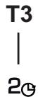
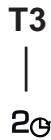
| T3 | Turns the Motor on at speed two | Buttons T1+T3 are lit. |
| Press and hold for 2 seconds to activate switch-off with a 30 minute delay (Motor+Lights). It is possible to change the operating speed with this function activated. | Buttons T1+ (T2 or T3 or T4, respectively) flash. | |
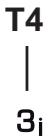
| T4 | Turns the Motor on at speed three | Buttons T1+T4 are lit. |
| Press and hold for 2 seconds to activate Intensive speed with a timer set to 6 minutes, after which it returns to the speed that was set previously. Suitable to deal with maximum levels of cooking fumes. | The Button flashes. | |
| L | Turns the Lighting system on and off at maximum intensity. | Button on |
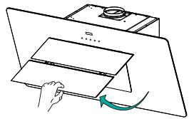
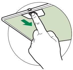
Opening Panel
- Open the Panel by pulling it.
- The panel can be locked in any position.
- Clean the outside with a damp cloth and neutral detergent.
- Clean the inside using a damp cloth and neutral detergent; do not use wet cloths or sponges, or jets of water; do not use abrasive substances.
Grease filters
CLEANING METAL SELF- SUPPORTING GREASE FILTERS
- The filters must be cleaned every 2 months of operation, or more frequently for particularly heavy usage, and can be washed in a dishwasher.
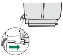
- Pull the comfort panels to open them.
- Remove the filters one by one pushing them towards the back side of the hood unit and simultaneously pulling downwards.
- Any kind of bending of the filters has to be avoided when washing them. Before fitting them again into the hood make sure that they are completely dry. (The colour of the filter surface may change throughout the time but this has no influence to the filter efficiency).
- When fitting the filters into the hood pay attention that they are mounted in correct position the handle facing outwards.
- Close the comfort panel.
Activated charcoal filter (Recirculation version)
These filters are not washable and cannot be regenerated, and must be replaced approximately every 4 months of operation, or more frequently with heavy usage.
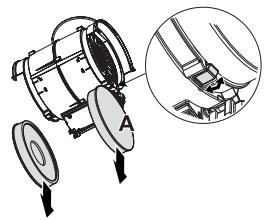
REPLACING THE ACTIVATED CHARCOAL FILTER
- Open the comfort panels pulling them downwards.
- Remove the metal grease filters
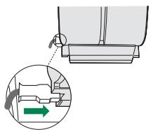
- Remove the saturated activated charcoal filter as shown (A).
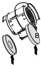
- Fit the new filters (B).
- Replace the metal grease filters.
- Close the comfort panels.
Lighting unit
Warning: This appliance is fitted with a white LED lamp classed as 1M according to EN 60825-1: 1994 + A1:2002 + A2:2001 standards; maximum optical power emitted @439nm: 7 W . Do not look directly at the light through optical devices (binoculars, magnifying glasses...).
- For replacement contact technical support. ("To purchase contact technical support")

a_i = 70%
jll jll lalac elil yall lc log aill
Jaiydu jolll
"4444" 5aall pabll gji jbi
:
jiall jalll 1
J 8
-
- a j k l s y d j n j j j j j j j j j j j j j j j j j j j j j j j j j j j j j j j j j j j j j j j j j j
00000000000000000000000000000000000000
j 1
i 15 12 1 1 1 1 1 1 1 1 1 1 1 1 1
1
1 1
aill
aIiJg cIbii Ioc yIyIyIyIyIyIyIyIyIyIyIyIyIyIyIyIyIyIyIyIyIyIyIyIyIyIyIyIyIyIyIyIyIyIyIyIyIyIyIyIyIyIyIyIyIy
jL jlll lil l l l l l l l l l l l l l l l l l l l l l l l l l l l l l l l l l l l l l l l l l l l l l l l l l l l l l l l l l l l l l l l l l l l l l l l l l l l l l l l l l
LgS
faiiaial 1j jai aiaial bao gao 1aai 1
cbw jj 788 auaa g
164 164 (1)
540 4aLwgeo jyjgall blln 140 4aLwge (2) gaiiabaiiae Juaa la
. 1
.
Aaall bai (1) 0 12
alallblai (2)08jbi
(1)a11a 1
(2) _g^g_g 11
()
(jall jSo) jsall oljg yge 12 2-1 7.2.1
yall sbaal bilg
aillwglllc
(a#d#jX)x7.2.1
a
iiDall gai jsl o cdo
aalallblill 008 jbi ciil
11 1
12a (4.2 x 44.4)
(c)gj
aalal alalal y aalal yall glal
Jlllal 11a 1111r Vr
11a 1
aJgJn Jn Vr aadall JdJn gJd Jn Jdaill
a.s. sol
.12a J
jll jjjgglg c
12c 4
).6.5x2.9(
g2abwjzglg 8 aagall
(2.9x9.5)12d
(20 1j jai jai)
Jauaiall jiaiall abw y waaill sluaal jilll glsl
(jlllglj)JLJnJyBGLJyBGLJyBGLJyBGLJyBGLJyBGLJyBGLJyBGLJyBGLJyBGLJyBGLJyBGLJyBGLJyBGLJyBGLJyBGLJyBGLJyBGLJyBGLJyBGLJyBGLJyBGLJyBGLJyBGLJyBGLJyB
#


"aaiaaaii aaiy aaiy aaiy aaiy
Franke S.p.a.
Via Pignolini,2
37019 Peschiera del Garda (VR)
www.franke.it