
TM-J7200 - Multifunction thermal printer EPSON - Free user manual and instructions
Find the device manual for free TM-J7200 EPSON in PDF.

| Product Type | Multi-function thermal printer (inkjet) for receipts and single sheets |
| Brand and Model | Epson TM-J7200 (or TM-J7700) |
| Dimensions (W × D × H) | TM-J7200: 195 × 260 × 188 mm; TM-J7700: 251 × 260 × 188 mm |
| Weight | Approximately 5.1 kg (TM-J7200) or 5.8 kg (TM-J7700) including cartridge |
| Power Supply | Dedicated AC adapter PS-180 (model M159E), input 24 V DC ±7%, typical consumption 15.9 W (operating), 1.8 W (standby) |
| Printing Method | Serial dot matrix inkjet, monochrome (black), resolution 600 dpi, max speed 23.2 lines/sec (76 mm roll) |
| Supported Paper Types | Roll (widths 57.5 / 69.5 / 76 / 82.5 mm) and single sheet (68–230 mm × 68–297 mm) |
| Ink Cartridge | SJIC33P(K) black pigment ink, with low-level detection (flashing Ink LED) |
| Software Functions | ESC/POS command system, barcode printing (UPC-A, EAN, CODE39, etc.) and 2D symbols (QR, PDF417, DataMatrix, etc.) |
| Maintenance and Cleaning | Clean the case with a dry or damp cloth (no solvents); clean the print head via the Cleaning button (≥3 s); print test via self-test |
| Safety | Warnings: use specified adapter, avoid dust/moisture, do not disassemble, cut power if abnormal, keep cartridges out of reach of children |
| Consumables and Repairability | Print head (3.7 billion shots/nozzle), auto cutter (1.5 million cuts), roll mechanism (15 million lines). Contact qualified technician for replacement of maintenance parts. |
| Interfaces | Ethernet 10/100BASE-TX, USB 2.0 Full Speed (type B), connector for cash drawer and optional customer display |
| Operating Temperature and Humidity | 10 to 35 °C, 20 to 80% RH (no condensation) |
| Country of Manufacture | Manufactured by Seiko Epson Corporation (Japan) |
Frequently Asked Questions - TM-J7200 EPSON
User questions about TM-J7200 EPSON
0 question about this device. Answer the ones you know or ask your own.
Ask a new question about this device
Download the instructions for your Multifunction thermal printer in PDF format for free! Find your manual TM-J7200 - EPSON and take your electronic device back in hand. On this page are published all the documents necessary for the use of your device. TM-J7200 by EPSON.
USER MANUAL TM-J7200 EPSON
Describes features of the product.
Setup
Describes setup and installation of the product and peripherals.
Advanced Usage
Describes advanced usage methods for the product.
Application Development Information
Describes how to control the printer and necessary information when you develop applications.
Handling
Describes how to handle the product.
Appendix
Describes general specifications and character code tables.
Cautions
- No part of this document may be reproduced, stored in a retrieval system, or transmitted in any form or by any means, electronic, mechanical, photocopying, recording, or otherwise, without the prior written permission of Seiko Epson Corporation.
The contents of this document are subject to change without notice. Please contact us for the latest information. - While every precaution has been taken in the preparation of this document, Seiko Epson Corporation assumes no responsibility for errors or omissions.
- Neither is any liability assumed for damages resulting from the use of the information contained herein.
- Neither Seiko Epson Corporation nor its affiliates shall be liable to the purchaser of this product or third parties for damages, losses, costs, or expenses incurred by the purchaser or third parties as a result of: accident, misuse, or abuse of this product or unauthorized modifications, repairs, or alterations to this product, or (excluding the U.S.) failure to strictly comply with Seiko Epson Corporation's operating and maintenance instructions.
- Seiko Epson Corporation shall not be liable against any damages or problems arising from the use of any options or any consumable products other than those designated as Original Epson Products or Epson Approved Products by Seiko Epson Corporation.
Trademarks
EPSON is a registered trademark of Seiko Epson Corporation.
Exceed Your Vision and ESC/POS are registered trademarks or trademarks of Seiko Epson Corporation.
Microsoft, Windows, and Windows Vista are registered trademarks of Microsoft Corporation in the United States and/or other countries.
All other trademarks are the property of their respective owners and used for identification purpose only.
ESC/POS® Command System
Epson ESC/POS is a proprietary POS printer command system that includes patented or patent-pending commands. ESC/POS is compatible with most Epson POS printers and displays.
ESC/POS is designed to reduce the processing load on the host computer in POS environments. It comprises a set of highly functional and efficient commands and also offers the flexibility to easily make future upgrades.
© Seiko Epson Corporation 2017. All rights reserved.
For Safety
Key to Symbols
The symbols shown below are used in this manual in order to ensure safety and proper use of this product and to prevent danger to customers and other persons, and property damage. The symbols indicate the precaution levels as described below. Be sure that you completely understand their meaning before reading this manual.
| WARNING | You must follow warnings carefully to avoid serious bodily injury. |
| CAUTION | Provides information that must be observed to prevent damage to the equipment or loss of data. ·Possibility of sustaining physical injuries. ·Possibility of causing physical damage. ·Possibility of causing information loss. |
| CAUTION | Provides information that must be observed to avoid damage to your equipment or a malfunction. |
| NOTE | Provides important information and useful tips. |
Cautions on Installation
| CAUTION | ·Do not install/store the product in an unstable location or in a location subject to vibration from other devices. Equipment may fall or collapse, causing breakage and possible injury. ·Do not install the product in a location exposed to oily smoke or dust, or in a humid location. Doing so may cause electric shock or fire. ·Place this product near a wall outlet where the plug can be easily unplugged. ·Use this product in the environment described in this manual. Failure to do so may damage the product or cause injuries. (See "Product Specifications" on page 95.) |
Cautions on Power Supply

WARNING
- Be sure to use the specified AC adapter. Connection to an improper power source may cause fire. (See "Product Specifications" on page 95.)
- Do not allow dust or foreign materials to adhere to the power plug. Accumulated dust or foreign material may cause electric shock or fire.
- Insert the power plug securely into the socket. Failure to insert the plug securely may cause electric shock or fire.
- For the power cable, use either the included one or a designated one that meets the relevant safety standards of the area where you plan to use it.
- Do not use it for any device other than the designated device.
-
Do not use a damaged power cable. Doing so may cause electric shock or fire. Contact qualified service personnel for advice if the power cable is damaged. Observe the following points so as not to damage the power cable:
-
Do not modify the power cable.
- Do not place heavy objects on the power cable.
- Do not forcibly bend, twist or pull the power cable.
-
Do not locate the power plug near a heating device.
-
Do not hold the power plug with a wet hand. Doing so may cause electric shock.
- Do not connect too many power cables to one outlet. Doing so may cause fire.
- Disconnect the power plug from the outlet on a periodical basis, and clean the areas around and between the blades. Leaving the power plug connected to the outlet for a long period of time may cause dust to accumulate on the blade root, resulting in a short-circuit or fire.
- Hold the plug and do not pull the cable when disconnecting the power plug from the outlet. Pulling the cable may damage the cable or deform the plug, causing electric shock or fire.

CAUTION
- To ensure safety, unplug this product before leaving it unused for an extended period.
Cautions on Handling
| WARNING | ·Do not use this product in a location with volatile substances such as alcohol or paint thinner, or near fire. Doing so may cause electric shock or fire. ·Shut down the product immediately if it produces smoke, a strange odor, or unusual noise. Continued use may cause electric shock or fire. Immediately unplug the product when a fault or other problem occurs, and contact qualified service personnel. ·Shut down the product immediately if water or other liquid spills into this product. Continued use may cause electric shock or fire. Immediately unplug the product and contact qualified service personnel. ·Never disassemble or repair this product. Tampering with this product may result in injury or fire. ·Do not use this product in an environment where inflammable gas or explosive gas may exist. Do not use aerosol sprayers containing flammable gas inside or around this product. Doing so may cause fire. ·Do not connect cables in ways other than those mentioned in the manual. Doing so may cause fire. (See "Connecting the AC Adapter" on page 30, "Connecting the Printer to the Host Devices" on page 34.) ·Do not connect a telephone line to the drawer kick connector or the DM-D connector; otherwise the printer and the telephone line may be damaged. ·Do not connect a LAN cable to the DM-D connector; otherwise the connected device may be damaged. ·Do not connect a telephone line to the drawer kick connector; otherwise the printer and the telephone line may be damaged. ·Do not touch the areas inside the product other than those mentioned in this manual. Doing so may cause electric shock or burns. ·Do not insert metal or flammable materials, or allow them to fall into the product. Doing so may cause electric shock or fire. |
| CAUTION | ·Do not allow anyone to stand or place heavy objects on top of this product. Equipment may fall or collapse, causing breakage and possible injury. ·Install the cables and optional products in the proper direction according to the proper procedures. Failure to install correctly may cause fire or injury. Follow the instructions in this manual to install them properly. (See "Connecting the AC Adapter" on page 30, "Connecting the Printer to the Host Devices" on page 34.) ·Before moving the product, shut down and unplug the product, and make sure that all the cables are disconnected. Failure to do so may damage a cable, causing electric shock or fire. ·Do not store or transport the product in a tilted, standing or upside-down position. Doing so may cause the ink to leak. |
Cautions on the Ink Cartridge

CAUTION
- The usable ink cartridges vary depending on the product. Use an ink cartridge that matches your printer.
(See "Product Specifications" on page 95, "Ink cartridge" on page 111.) - Do not touch the IC chip on the cartridge. Doing so may cause operating/printing malfunction.
- This product uses ink cartridges equipped with an IC chip that monitors the amount of ink used by each cartridge. Cartridges are usable even if they are removed and reinstalled. However, if an ink cartridge in which little amount of ink remains is removed and reinstalled, it may not be usable. Some ink is consumed each time cartridges are installed because the product automatically checks their reliability.
- Since ink cartridges are designed to stop the operation before ink runs out completely to maintain the quality of the print head, some ink remains in the used ink cartridge.
- Ink is also consumed during head cleaning maintenance.
- Do not turn off the product or open the Front cover while charging Ink Power LED is flashing. Opening the cover may cause the ink to be recharged, resulting in more ink being consumed. Also, it may cause printing malfunction.
- Do not disassemble the ink cartridge. Doing so may cause ink to adhere eyes and skin.
- Do not disassemble and remodel the ink cartridge. Doing so may cause printing malfunction.
- Use of an old ink cartridge may result in reduced print quality. Use it up within six months after opening the package. The usage period for ink cartridges is printed on the packaging of individual ink cartridges.
- If ink contacts your skin, eyes, or mouth, take the following actions.
- When it gets onto your skin, immediately wash the area with soap and water.
- When ink gets into your eyes, immediately flush them with water. Leaving the ink as is may result in bloodshot eyes or mild inflammation. If something is wrong, immediately consult with a doctor.
- When ink gets into your mouth, immediately spit it and consult with a doctor.
- There may be some ink around the ink supply port on the removed ink cartridge. Take care so that it does not stain the desk or other surface.
- Do not remove the ink cartridge, except when you replace it.
- Do not open the ink cartridge package until you are ready to install it in the product.
- Do not shake the ink cartridge too hard. The ink cartridge may leak if you shake it around too much or push the sides strongly.
- Do not allow foreign objects to fall into the cartridge installation section. Doing so may cause printing malfunction. Remove any object that might have fallen into the installation section, taking care not to damage the section.
- When ink is charged for the first time (right after purchase), ink is consumed for filling the print head nozzle (ink discharge holes) to get ready for printing. That is why the number of the printable sheets may be fewer than for the cartridges to be installed later.
- Dispose the ink cartridges properly following the law or regulations of your country and area.
- If you turn the power off the product using the power switch, the print head is automatically capped, which prevents the ink from drying. After installing the ink cartridges, be sure to turn the power off using the power switch when you are not using the product. Do not pull out the power plug or trip the breaker while the power is on.
- Keep ink cartridges out of the reach of children.
- A cool and dark place is recommended to store ink cartridges.
- If the ink cartridge is stored in a cold place for a long period of time, let it warm up at least 3 hours before using it.
- If moving or transporting the product after the ink cartridges are installed, leave them installed during the moving or transporting process.
Restriction of Use
When this product is used for applications requiring high reliability/safety, such as transportation devices related to aviation, rail, marine, automotive, etc.; disaster prevention devices; various safety devices, etc.; or functional/precision devices, etc., you should use this product only after giving consideration to including fail-safes and redundancies into your design to maintain safety and total system reliability. Because this product was not intended for use in applications requiring extremely high reliability/safety, such as aerospace equipment, main communication equipment, nuclear power control equipment, or medical equipment related to direct medical care, etc., please make your own judgment on this product's suitability after a full evaluation.
About this Manual
Aim of the Manual
This manual was created to provide information on development, design, and installation of POS systems and development and design of printer applications for developers.
Manual Content
The manual is made up of the following sections:
Chapter 1 Product Overview
Chapter 2 Setup
Chapter 3 Advanced Usage
Chapter 4 Application Development Information
Chapter 5 Handling
Chapter 6 Troubleshooting
Appendix Product Specifications
Character Code Tables
Contents
For Safety 3
Key to Symbols 3
Cautions on Installation 3
Cautions on Power Supply. 4
Cautions on Handling 5
Cautions on the Ink Cartridge 6
■ Restriction of Use 7
About this Manual 8
Aim of the Manual 8
Manual Content. 8
Contents. 9
Product Overview 13
■ Features 13
Product Configurations 15
Models. 15
Accessories 15
Part Names and Functions 16
Front Side 16
Control panel. 17
Rear Side Connectors 18
Online and Offline. 19
Status and Errors 20
■ NV Memory (Non-Volatile Memory) 22
NV Graphics Memory 22
User NV Memory 22
Memory Switches 22
Maintenance Counter 22
Setup. 23
■ Installing the Printer 23
Notes for when installing the device 23
■ Removing the Protective Materials and Tape 24
Changing the Roll Paper Width 26
Adjusting the Roll Paper Near-End Sensor 28
- Connecting the AC Adapter 30
■ To install the AC Adapter (only for the TM-J7700) 31
- Connecting the Printer to the Host Devices 34
- Connecting the Cash Printer 35
Required specifications of cash drawers 35
Connecting the drawer kick cable. 36
■ Installing the Customer Display 37
■ Attaching the Power Switch Cover 38
Advanced Usage 39
■ Software Settings 39
Software Setting Mode Functions 40
■ Network Settings 41
Setup methods 43
Flow of Setup 43
Setup using EpsonNet Config (Web version) 44
Setup using arp/ping commands 45
MAC Address Confirmation. 45
Ethernet setting mode 46
Setting/Check Modes 47
Self-test Mode 49
NV Graphics Information Print Mode 53
Customize Value Setting Mode 54
Ethernet Setup Mode 56
Hexadecimal Dumping Mode 57
■ Printing a Status Sheet 58
Printing method 58
■ EpsonNet Config (Web Version) 59
Information Menu 59
Configuration Menu 60
Application Development Information 63
Controlling the Printer 63
ESC/POS 63
■ Software. 64
Development Kit 64
Drivers 64
Utilities 65
Download 65
■Turning off the Printer without Using the Power Switch 66
■ Printing Barcodes/2-dimensional Symbols 67
Notes on printing barcodes 67
Notes on printing 2-dimensional symbols 68
Handling 69
■ Installing/Replacing the Roll Paper 69
Notes on Use 72
Inserting Slip Paper 73
Notes on Use 74
■ Installing/Replacing the Ink Cartridge 75
Notes on Use 77
■ Removing Jammed Paper 79
For roll paper. 79
For slip papers 80
■ Test Printing 81
■ Cleaning the Printer. 82
Cleaning the Printer Case. 82
Cleaning the Print Head. 82
Preparing for Transport. 83
Troubleshooting 85
■ Error LED is On/Flashing 86
■ Ink LED is On/Flashing 87
Ink LED is flashing 87
Ink LED is on. 87
■ Print Quality Problem 88
Misaligned print position 88
Print result on slip paper is skewed. 88
Missing print data. 88
Paper gets dirty/stained with ink 88
■ When slip paper is set, paper is discharged resulting an error 89
Setting slip paper does not start printing 90
Cut sheet LED is flashing continuously. 90
Cut sheet LED repeats a double-flashing pattern 90
Cut sheet LED is off 90
■ Paper jam 90
■ Printing from the computer is disabled/Printing was suddenly disabled 91
Printer is offline 91
Reconnect the printer and the computer 91
Check installation of printer driver 91
■ Power does not turn on 92
"A maintenance part must be replaced." is printed 92
Appendix 93
■ Specifications of Interface and Connector 93
USB Interface 93
Ethernet Interface 94
■ Product Specifications 95
Printing Specifications 97
Character Specifications 100
Paper Specifications 102
Printable Area. 104
Printing and Cutting Positions. 107
Electrical Characteristics 107
Environmental Conditions 108
External Dimensions 109
Ink cartridge 111
■ Character Code Tables. 112
Product Overview
This chapter describes features of the product.
Features
This product is a high-end POS ink jet printer that can print on both receipt paper (roll paper) and slip paper.
Printing
- Can print on both roll paper and slip paper
- 600-dpi high-quality fine printing
- Achieves super-fast printing at approx. 23.2 lps (76 mm 2.99" paper width). [lps: lines per second] For the print speed, see "General Print Speed" on page 98.
Ink cartridge
- Uses pigment ink with compared with Dye ink resistance to light and water.
- The ink-low detection function notifies you when it is nearly time to replace the ink cartridge by flashing the Ink LED.
Handling
- Easy drop-in roll paper loading.
- Uses the wide slip entrance and mechanical form stopper to enable stable slip printing.
Software
- Based on the ESC/POS Command System.
- Printing of various types of bar codes, GS1-DataBar, and 2-dimensional symbols (PDF417, QR code, MaxiCode, Composite Symbology, Aztec Code, DataMatrix) is supported.
- A maintenance counter function is supported.
- Various language support. (Code Page)
- Windows utility for printer setup (TM-J7200 TM-J7700 Utility, TM-J7200 TM-J7700 Printer Model Setting Utility) is provided.
- Printer driver is provided. (EPSON Advanced Printer Driver, EPSON OPOS ADK, EPSON OPOS for .NET, EPSON JavaPOS)
Environment
- Low noise printing, ideal for use in quiet environments.
- Ink jet printer that can print on normal paper at a low running cost.
Others
- Can be equipped with an Epson customer display. (DM-D110 and DM-D210 only)
- Can be equipped with the cash drawer.
Product Configurations
Models
TM-J7200
TM-J7700
Accessories
Included
- Roll paper (Paper width 76mm {2.99")}
Dedicated ink cartridge SJIC33P(K) - Setup Guide and sheets
- Manual CD
Power switch cover - AC adapter PS-180
- AC cable
- USB cable
-
Power source fixing plate × 1 (Screw × 2 )
-
For TM-J7700 only
Consumables
- Ink cartridge SJIC33P(K)
Part Names and Functions
Front Side
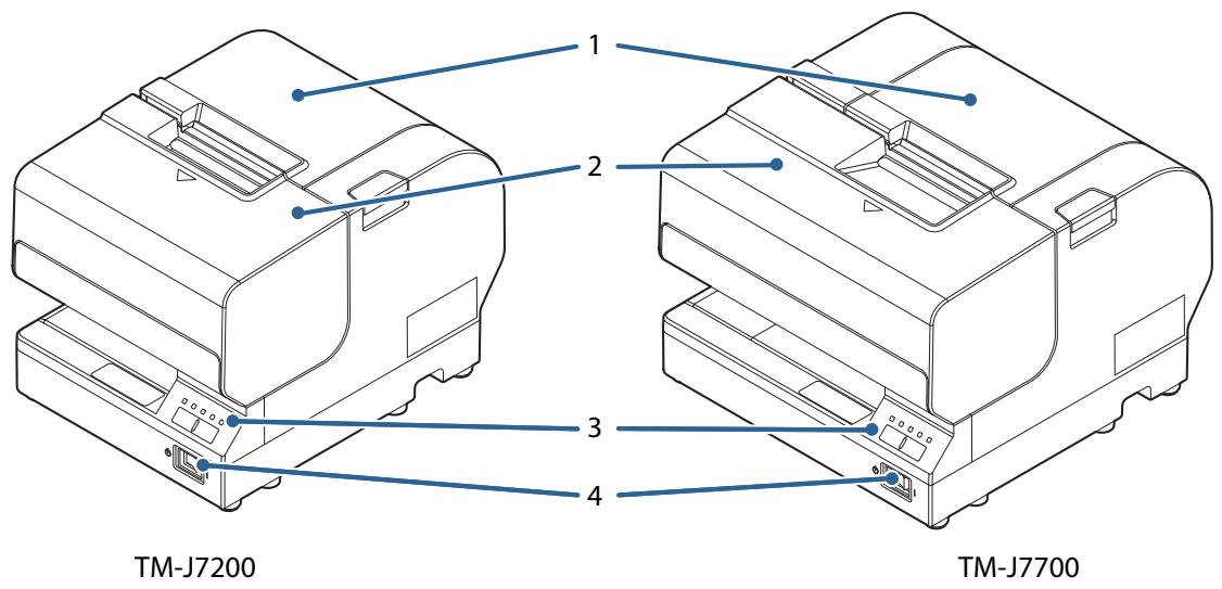
| 1 | Roll paper cover | Open this cover to install/replace the roll paper. |
| 2 | Front cover | Open this cover to install/replace the ink cartridge. |
| 3 | Control panel | For details on LED, see "Control panel" on page 17. |
| 4 | Power Switch | Turns the printer on/ off. |
Control panel
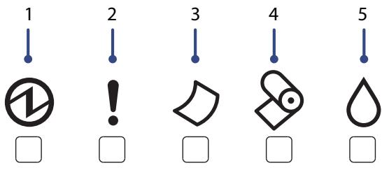
| 1 | Power LED | Lights up when the printer is turned on. Flashes during head cleaning and other operations such as when turning the printer on/off. |
| 2 | Error LED | Lights up when the printer is offline due to the following conditions. ·The ink cartridge is not installed or requires replacement. ·The roll paper has run out. ·The Front cover/Roll paper cover is open. ·During power-on initialization. ·During power-off processing. ·When the printer is waiting for printing or insertion of another slip to be printed while the printer is waiting for removal of a slip paper. Off when the printer is online. Flashes when an error occurs. (See "Error LED is On/Flashing" on page 86.) |
| 3 | Cut sheet LED | Lights up when slip paper (cut sheet) is selected as the print sheet. Off when roll paper is selected as the print sheet. Flashes when the printer is in the slip paper insertion or removal waiting state. |
| 4 | Paper LED | Lights up when the roll paper has run out or is near the end. |
| 5 | Ink LED | Lights up when the ink cartridge is not installed or requires replacement. Off when the ink cartridge is installed and there is sufficient ink. Flashes when the ink is low. |
| 6 | Feed Button | Press this button to feed the roll paper or slip paper. Paper cannot be fed using this button in the following cases: ·The Front cover/ Roll paper cover is open. ·Printer is in the slip paper insertion or removal state. ·When head cleaning is being performed or an error has occurred with any sheet selected. |
| 7 | Cleaning Button | Press this button for more than three seconds to perform head cleaning. |
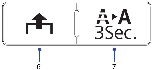
Rear Side Connectors
| 1 | DM-D connector | For connecting the customer display. Be careful not to insert a telephone jack (RJ11) or the modular cable of the cash drawer into the DM-D connector. Doing so could damage the printer or the drawer. |
| 2 | Drawer kick connector | For connecting a modular cable for the cash drawer. |
| 3 | Power supply connector | For connecting the power cable. |
| 4 | USB connector (Type B) | For connecting a USB cable. |
| 5 | Ethernet connector | For connecting a LAN cable. Be careful not to insert a telephone jack (RJ11) or the modular cable of the cash drawer into the Ethernet connector. Doing so could damage the printer or the drawer. |
Online and Offline
Online
When the product is ready for normal printing, it is "online".
Offline
The printer automatically goes offline under the following conditions:
- While the printer power is turning on/off
-
When any of the following covers are opened:
-
Roll paper cover
- Front cover
While paper is fed using the Feed button
- When the printer stops printing due to a paper end (when the paper out detector detected the paper out)
- When no ink cartridge is installed
- When it is time to replace the ink cartridge
- During the print head cleaning
- When an error has occurred
Status and Errors
The status of the printer is indicated by lit and flashing LEDs.
CAUTION
You cannot print when an error has occurred.
NOTE
You cannot identify the error by the flashing patterns of the LEDs. Develop the application so that users can identify the error description and check the solutions.
O: OFF

ON
: Flashing
(x): Flashing x times
- : Changes depending on whether or not paper is detected.
| Power LED | Error LED | Cut sheet LED | Paper LED | Ink LED | Printer Status | |
| Non-Error | ● | ○ | - | - | - | Online |
| ◇ | ● | ○ | ○ | ○ | During Power Off Sequence | |
| ◇ | - | ○ | - | - | While initializing after turning on the power | |
| ● | ○ | - | - | - | Pushed for feeding | |
| ● | ● | - | ● | - | Roll paper cover open while not printing | |
| ● | ● | - | - | - | Front cover open while not printing | |
| ● | ○ | - | ● | - | Roll paper near-end | |
| ● | ● | - | ● | - | No roll paper | |
| ● | ○ | ● | - | - | Printing on Slip | |
| ● | ○ | ◇ | - | - | Waiting for Slip insertion | |
| ● | - | ◇(2) | - | - | Removal for Slip ejection | |
| ● | - | - | - | ◇ | Ink Status: Ink low | |
| ● | ● | - | - | ● | Ink Status: Ink replace | |
| ◇ | ○ | - | - | - | During Ink Cleaning | |
| ◇ | - | - | - | - | During network startup when the power is turned on. *When LED indicator when I/F starting is enabled, it links to printer status. | |
| Error | ● | ● | - | - | - | Roll paper cover open error. Auto Recoverable errors |
| ● | ○(1) | - | - | - | Autocutter error | |
| ● | ○(2) | - | - | - | Carriage detection error | |
| ● | ○(4) | - | - | - | Cut sheet error | |
| ● | ○(6) | - | - | - | Roll paper cover open error | |
| ● | ○ | - | - | - | Unrecoverable Errors CAUTION: Turn off the power immediately when an unrecover-able error occurs. If the same error occurs again even after turning the power back on, contact qualified service personnel for advice. |
- : Changes depending on whether or not paper is detected.
NV Memory (Non-Volatile Memory)
The printer's NV memory stores data even after the printer power is turned off. NV memory contains the following memory areas for the user:
- NV graphics memory
- User NV memory
- Memory switches
- User-defined page
- Maintenance counter
CAUTION
As a guide, NV memory rewriting should be used 10 times or less a day.
NV Graphics Memory
Graphics, such as shop logos to be printed on receipts, can be registered.
To register graphics, use the TM-J7200 TM-J7700 Utility.
To check the registered graphics, use the TM-J7200 TM-J7700 Utility or the NV graphics information print function for printing.
NOTE
For information about how to use the NV graphics information print mode, see "NV Graphics Information Print Mode" on page 53.
User NV Memory
You can store and read text data for multiple purposes, such as for storing a note including customizing or maintenance information of the printer.
Memory Switches
With the memory switches, which are software switches for the printer, you can configure various settings of the printer. For information about the memory switch, see "Software Settings" on page 39.
Maintenance Counter
With this function, printer information, such as the number of lines printed, the number of autocuts, and printer operation time after the printer starts working, is automatically stored in printer's memory. You can read the counter information to use it for periodical checks or part replacement.
NOTE
You can also check the length of paper feed and number of times of autocutting with the TM-J7200 TM-J7700 Utility.
Setup
This chapter describes setup and installation of the product and peripherals.
Installing the Printer
Notes for when installing the device
- On an area larger than the bottom surface of the product.
- In a location free of vibration and impacts.
- In a location that is firm, stable, and horizontal.
- In a location where a dedicated power outlet is available.
- In a location where you can set and remove paper without difficulty.
- In a location with sufficient space around the printer to allow for installation of accessories, replacement of consumable products, and daily cleaning.
- In a location that meets the conditions listed in the specifications.
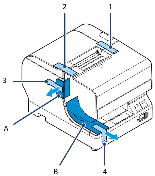
Removing the Protective Materials and Tape
Protective materials and tape are applied for protection against impacts during transportation. Remove them before installation.
NOTE
The Protective materials and packaging box will be required for future transportation. Keep them in a safe place.
TM-J7200
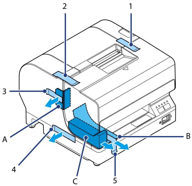
TM-J7700

Changing the Roll Paper Width
This printer allows for the paper width of the roll paper to be changed. It can be selected from four types: 57.5 mm 2.26" , 69.5 mm 2.74" , 76 mm 2.99" , and 82.5 mm 3.25" . (The default is 76 mm 2.99" .)
Follow the procedure below to change the paper width.
NOTE
- When changing the paper width, be sure to change the setting for the paper width by using the TM-J7200 TM-J7700 Utility or customize value. (See "Customize Value Setting Mode" on page 54)
- Do not change to wider paper width after using a narrower paper width. The autocutter blade may be worn and may not be able to cut cleanly.
1 Make sure the printer is turned off.
2 Open the Roll paper cover by pressing the cover open button.
3 Remove the screw holding the roll paper guide located on the left side of the roll paper holder.
4 Change the location of the roll paper guide to match the paper width to select the required paper width. Align the upper and lower grooves, and confirm that the protrusion is inserted in the hole on the bottom.
Use the removed screw to affix the guide.
Adjusting the Roll Paper Near-End Sensor
Adjust the roll paper near-end sensor in the following situations:
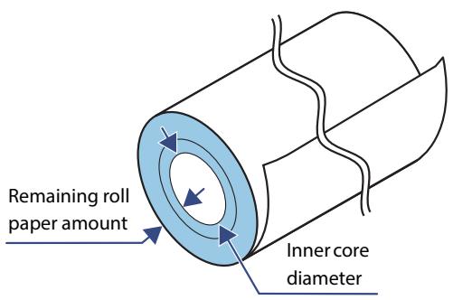
- To adjust the detection position according to the thickness of the roll paper core that is used
- To adjust the detection position for remaining roll paper amount
CAUTION
- The near end cannot be detected precisely, because the core shape varies slightly with each roll paper.
- In order for the roll paper near-end sensor to correctly detect the amount of paper remaining, use roll paper with an inner core diameter of 10mm0.39" or larger.
- If the roll paper is loose due to the paper quality, false detections could occur.
Use the following procedure to adjust the roll paper near-end sensor.
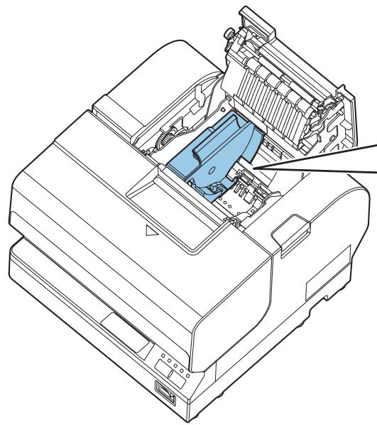
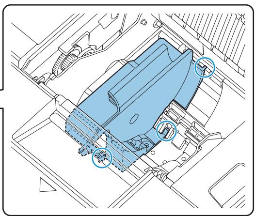
1 Open the Roll paper cover, and remove the roll paper.
2 Loosen the adjustment screw fastening the sensor.
3 Set the position of the sensor by moving the its tab.
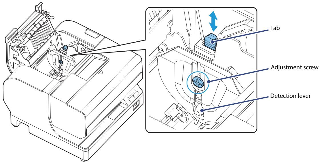
NOTE
The remaining roll paper amount will change depending on the slit location on the tab.
| Slit location on the tab | Remaining roll paper amount | |
| #4 | Approx. 5 mm {0.20"} | |
| #3 | Approx. 7 mm {0.28"} (Default setting) | |
| #2 | Approx. 8.5 mm {0.33"} | |
| #1 | Approx. 10 mm {0.39"} | |
4 Tighten the adjustment screw.
After completing the adjustments, check that the detection lever operates smoothly.
Connecting the AC Adapter

WARNING
- Be sure to use the specified AC adapter [PS-180 (model: M159E)]. Connection to an improper power source may lead to equipment damage, fire, or electric shock.
- Should a fault ever occur, immediately turn off the power to the printer and unplug the AC cable from the socket.
CAUTION
Use the AC cable provided with this printer.
Connect the AC Adapter by following the procedure below.
For the TM-J7700, you can connect an AC adapter to the underside of the printer. Follow the instructions to install it properly. (See "To install the AC Adapter (only for the TM-J7700)" on page 31)

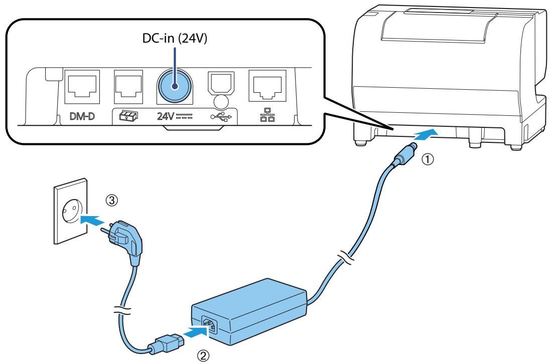
Confirm that the power switch is off.

Firmly insert the DC connector of the AC adapter into the DC-in ("24V") connector of the printer.

Firmly insert the AC cable connector into the AC port of the AC adapter.

Firmly insert the plug into a grounded wall outlet.

Set the AC adapter so that its label side is facing down.
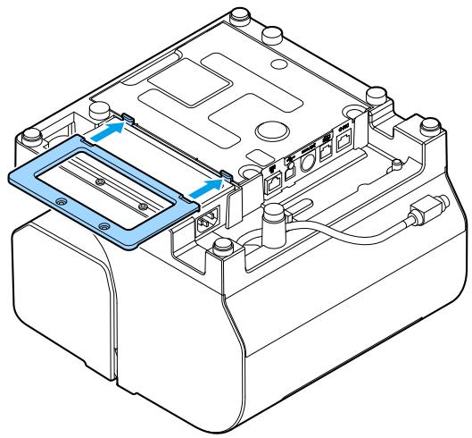
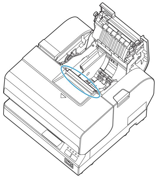
To install the AC Adapter (only for the TM-J7700)
Follow the procedure below to install the AC Adapter.
NOTE
Perform the following when installing the AC adapter.
- Be sure to use a dedicated AC adapter [PS-180 (model: M159E)].
- Install the AC adapter so that its label can still be seen after it is attached.
- Use a straight plug for the AC inlet side of the power cable. If you do use an L-shaped plug, install the printer near the power outlet and be sure that the plug can be easily disconnected.
- Be sure to thoroughly read and understand the information on the label of the AC adapter (rating, Warning/Cautions) before installing it to the printer unit.
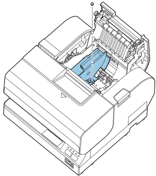
1 Turn the printer over.
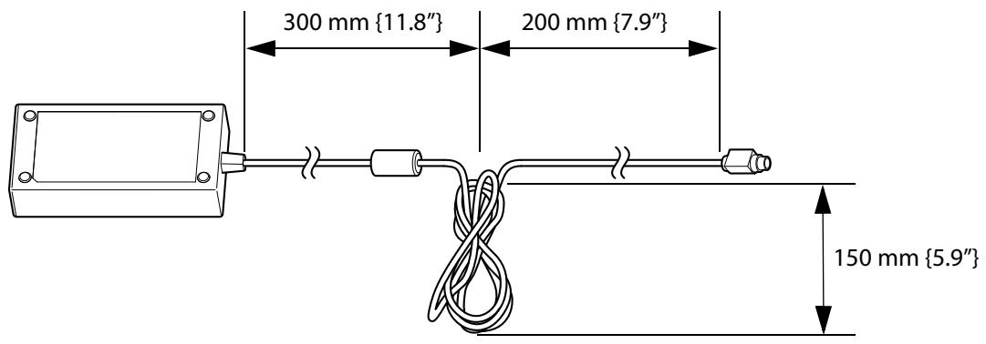
2 Bundle the DC cable of the AC adapter as shown in the illustration. The dimensions show are approximate and for use only as a rough guide.
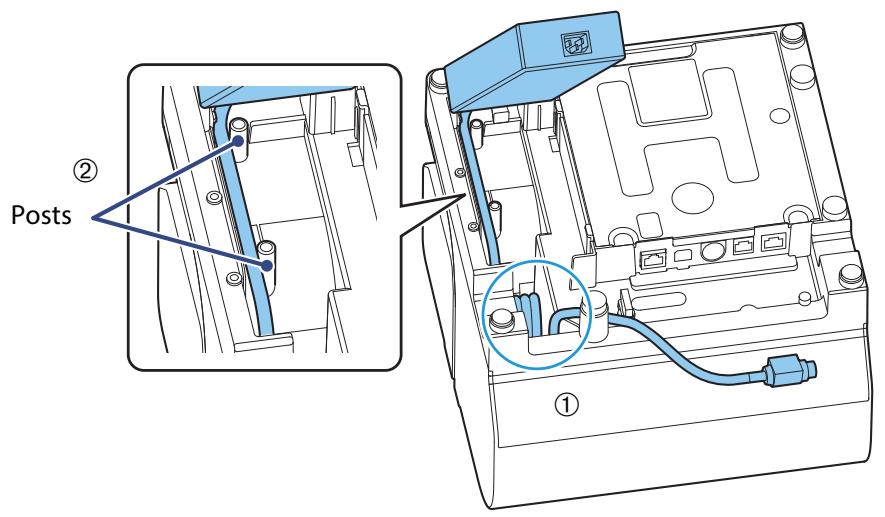
3 Set the bundled part of the DC cable into the empty space inside the printer indicated by the circle. Insert the DC cable next to the two posts on the bottom of the printer to securely store the adapter.
4 Place the AC adapter into the printer with the label side facing up.
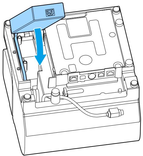
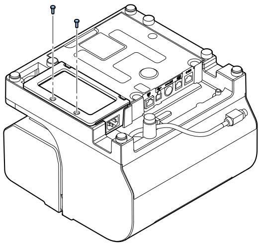
5 Align the depressions on the power source fixing plate with the hook protrusions on the main unit and gently push the plate to install.
6 Use the included screws (× 2) to attach the fixing plate.
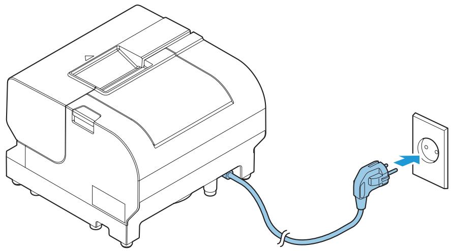
7 Connect the DC cable of the AC adapter to the power supply connector ("24V") and connect the AC cable to the AC adapter.
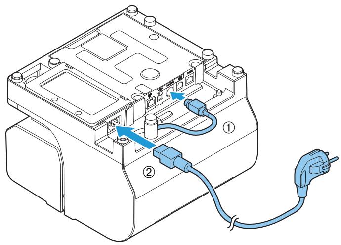
8 Turn the printer right side up and connect the AC cable plug to a power outlet.
Connecting the Printer to the Host Devices
Connect the interface cable to be used to the connector on the rear side of the printer.
(See "Rear Side Connectors" on page 18.)
Connect the cable to be used to either the USB type-B connector or Ethernet connector.

CAUTION
When using a USB cable, pass the cable through the wire saddle to prevent accidental disconnection.
TM-J7200
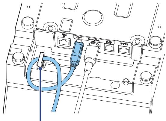
Wire saddle
TM-J7700
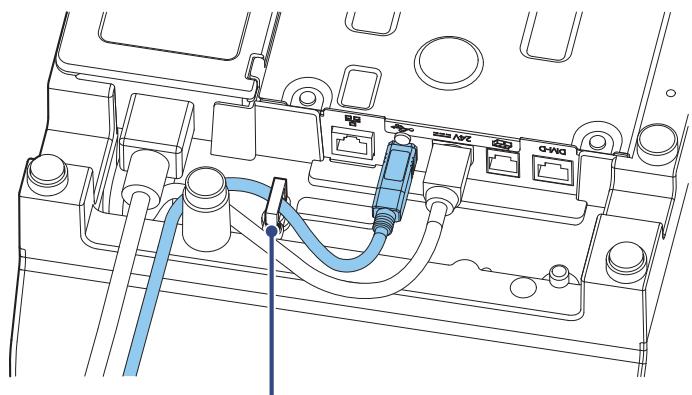
Wire saddle
Connecting the Cash Printer
CAUTION
- Two driver transistors cannot be energized simultaneously.
- Leave intervals longer than 4 times the drawer driving pulse when sending it continuously.
Required specifications of cash drawers
Specifications of drawers differ depending on manufacturer and/or model. When you use a drawer other than specified, make sure its specification meets the following conditions.
Otherwise, devices may be damaged.
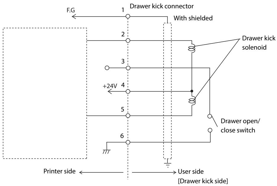
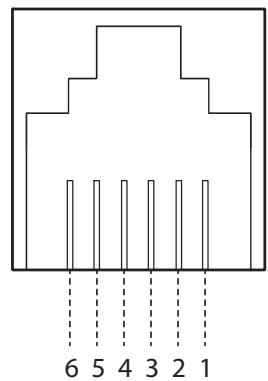
- The load, such as a drawer kick solenoid, must be connected between pins 4 and 2 or pins 4 and 5 of the drawer kick connector.
- When the drawer open/close signal is used, a switch must be provided between drawer kick connector pins 3 and 6.
- The resistance of the load, such as a drawer kick solenoid, must be 24 or more or the input current must be 1A or less.
- Be sure to use the 24V power output on drawer kick connector pin 4 for driving the equipment.
Drawer Connection Diagram
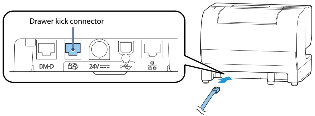
Connecting the drawer kick cable

WARNING
- Use a shielded cable for the drawer kick cable.
- When using cash drawer, make sure to use the correct connector pin (pin 4) for powering the cash drawer. Please see the "Drawer Connection Diagram" on page 35.
- Do not insert a telephone line into the drawer kick connector.
Doing so may damage the telephone line or printer.
Connect the drawer kick cable to the drawer kick connector by pressing firmly until the connector clicks into place.
Installing the Customer Display
A customer display and DP-502 (customer display fixing plate) can be installed.
For details, refer to DM-D110/DM-D210 Technical Reference Guide.
2
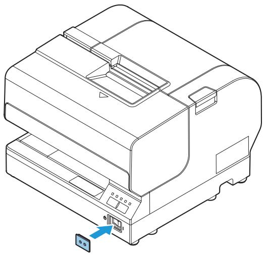
Attaching the Power Switch Cover
Attach the Power switch cover to prevent accidental operation of the power switch. Insert a sharp-pointed object into one of the holes on the Power switch cover to turn the power on or off accordingly. Use a sharppointed object to detach the cover.

WARNING
Unplug the product immediately if an accident occurs with the Power switch cover attached. Continued use may cause fire or shock.
Install the cover as shown in the illustration below.
Advanced Usage
Software Settings
With the memory switches and customized values, which are software settings for this printer, you can set the various functions.
For an outline of the functions, see the following section. Use the Software Setting Mode to set the memory switches.
| Item\Method | TM-J7200 TM-J7700 Utility for Windows | Software Setting Mode | |
| Memory Switches | Auto line feed | ✓ | ✓ |
| Handshaking (Condition for BUSY) | ✓ | - | |
| Connect to Customer Display | ✓ | - | |
| Autocutter Operation | ✓ | - | |
| Setting the conditions that cancel the receive buffer BUSY state | ✓ | - | |
| Number of characters per line on a slip | ✓ | - | |
| Number of characters per line on roll paper | ✓ | - | |
| Roll paper cover open during printing | ✓ | - | |
| Right margin of the slip *1 | ✓ | - | |
| Bottom margin of the slip *2 | ✓ | - | |
| Customized Values | Paper width | ✓ | ✓ |
| Command execution during offline | ✓ | ✓ | |
| LED indicator when I/F starting | ✓ | ✓ | |
| Method for canceling recoverable error | ✓ | - | |
| Logo | ✓ | - | |
| IP Address Config | ✓ | - | |
| DNS Config | ✓ | - | |
| Certificate Config | ✓ | - | |
| SSL/TLS Config | ✓ | - | |
| Ethernet Config | ✓ | - | |
| SNMP Config | ✓ | - | |
| Timeout Config | ✓ | - | |
| IP/Port Filter Config | ✓ | - | |
| Administrator Name and Location | ✓ | - | |
1: This appears only for TM-J7700.
2: This appears only for TM-J7200.
NOTE
For information about how to use the software setting mode, see "Customize Value Setting Mode" on page 54.
Software Setting Mode Functions
Auto line feed
Always disabled (Default setting)
Always enabled
Paper width
- 58 mm
- 70 mm
- 76 mm (Default setting)
- 82.5 mm
Command execution during offline
- Enabled
- Disabled (Default setting)
LED indicator when I/F starting
- Enabled
- Disabled (Default setting)
Autocutter Operation
- Enabled (Default setting)
- Disabled
Network Settings
The following explains the procedure for network settings in order to connect the product to your network.
| Articles | Parameters | Default | TM-J7200TM-J7700 Utility | Web Browser | Status Sheet | ||
| Reference | Setting | Reference | Setting | Reference | |||
| IP Address | (192.168.192.168) * | Yes | Yes | Yes | Yes | Yes | |
| Subnet Mask | (255.255.255.0) * | Yes | Yes | Yes | Yes | Yes | |
| Default Gateway Address | (0.0.0.0) * | Yes | Yes | Yes | Yes | Yes | |
| Acquiring the IP Address | Manual/ Auto(DHCP) | Auto(DHCP) | Yes | Yes | Yes | Yes | Yes |
| APIA | Enable/ Disable | Disable | Yes | Yes | Yes | Yes | No |
| ARP + Ping | Enable/ Disable | Disable | Yes | Yes | Yes | Yes | No |
| Administrator Name | (Up to 255 characters) | '' (no value) | Yes | Yes | Yes | Yes | No |
| Location/ Person | (Up to 255 characters) | '' (no value) | Yes | Yes | Yes | Yes | No |
| Password | (Up to 20 characters) | "epson" | No | Yes | No | Yes | No |
| Standard Community Name | (read only) | "public" | No | No | Yes | No | No |
| Community Name (read only) | (Up to 31 characters) | '' (no value) | Yes | Yes | Yes | Yes | No |
| Community Name (read/write) | (Up to 31 characters) | '' (no value) | Yes | Yes | Yes | Yes | No |
| IP Trap1 | Enable/ Disable | Disable | No | No | Yes | Yes | No |
| IP Trap2 | Enable/ Disable | Disable | No | No | Yes | Yes | No |
| Community Name(IP Trap #1) | (Up to 31 characters) | '' (no value) | No | No | Yes | Yes | No |
| Community Name(IP Trap #2) | (Up to 31 characters) | '' (no value) | No | No | Yes | Yes | No |
| IP Trap#1 Address | - | 0.0.0.0 | No | No | Yes | Yes | No |
| IP Trap#2 Address | - | 0.0.0.0 | No | No | Yes | Yes | No |
| Socket Timeout | 1-300sec /0 (no timeout) | 90 sec | Yes | Yes | Yes | Yes | No |
| Time Server Status | Success / Failure / Invalid | Invalid | Yes | Yes | Yes | Yes | Yes |
| Time Server Address | - | 0.0.0.0 | Yes | Yes | Yes | Yes | No |
- Default value when "Acquiring the IP Address" is set to "Manual".
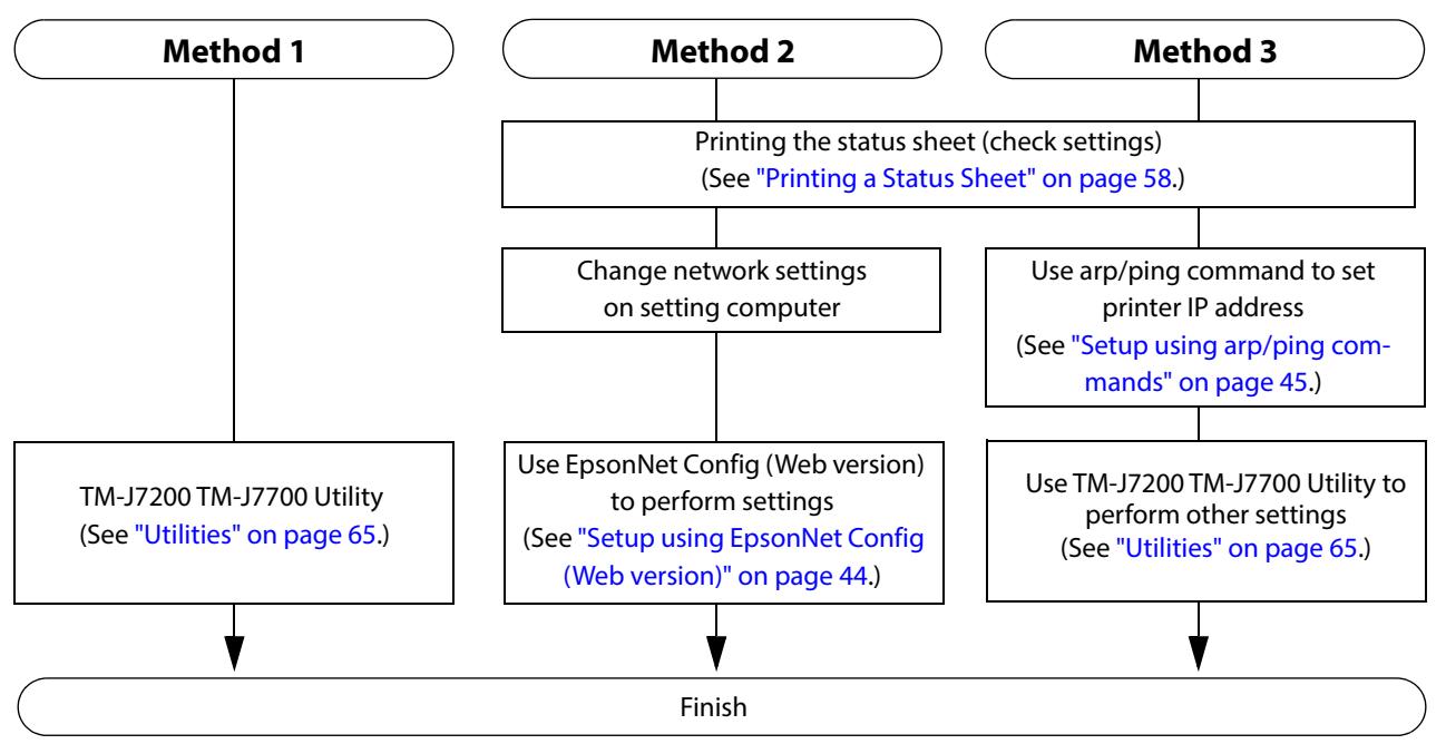
Setup methods
When you use "Acquiring the IP Address" for Auto (DHCP), you do not need to set the IP address. When you set the IP Address manually, follow one of the methods below.
There are three methods for set up.
Method 1: Setup using TM-J7200 TM-J7700 Utility
This method involves installation of the TM-J7200 TM-J7700 Utility to the computer for setup.
Setup is easiest when performed using a USB connection. Setup from an existing computer connected to the network is also available.
Download TM-J7200 TM-J7700 Utility from the Epson website.
Method 2: Setup using EpsonNet Config (Web version)
This method involves opening the Web application equipped in the printer from a Web browser to perform settings.
Because you specify the printer's IP address to open it, you need to set your computer to the same network segment as the printer.
Method 3: Setup using arp/ping commands
This method involves setting the printer's IP address in the setting computer's arp/ping commands, then using the setting tool to change the other settings.
The setting computer must be in the same segment as the printer. Also, settings can be done only when the printer's arp+ping IP setting is set to Enable.
Use TM-J7200 TM-J7700 Utility for settings other than the IP address.
Flow of Setup
Setup using EpsonNet Config (Web version)
Follow the steps below to start up EpsonNet Config (Web version), and check or change the settings.
CAUTION
- When setting up using the EpsonNet Config (Web version), you need to set the network settings for the device to the same network segment as the printer you want to connect to.
- The default setting uses an IP address for the printer provided by a DHCP server. Since you cannot complete setup if there are conflicting IP addresses on the network, make sure that there are no other devices on the network that conflict with the IP address provided by the DHCP server. If a DHCP server is not available, a fixed IP address (192.168.192.168) is set approximately one minute after turning on the printer. Also, if the Ethernet cable is not connected, connect the Ethernet cable and then run this process.
- When DHCP is enabled, the provided IP address is printed automatically. However, if the Ethernet cable is not connected, printing is not performed.
1 Connect the setting computer and the printer to the same network.
2 Perform network settings on the computer so that it is in the same segment as the printer's IP address.
Subnet mask: Same subnet mask as the printer
IP address: Same segment (same network address) as the printer, different host address
Check the values set in the printer on the status sheet.
E.g.)
| Printer | Setting computer | |
| Subnet mask | 255.255.255.0 | 255.255.255.0 |
| IP address | 192.168.192.168 | 192.168.192.2 |
3 Start up your Web browser and input the printer's IP address into the address field.
E.g.) http://192.168.192.168
NOTE
Under default settings, when you access EpsonNet Config (Web version) from your browser, an authentication warning message may be displayed.
4 Input your user name and password on the authentication window.
Input "epson" for both the user name and password. You can change the password in the [Optional] setting menu, under [Password].
5 Change the settings based on the network setting information you received from the network administrator.
Select an item from [Configuration] and change the setting.
After changing the necessary parameters, click the [Send] button.
The changes are sent to the printer.
7 Click the [Reset] button on the Web page displayed after sending.
The sent contents are enabled.
Depending on the changes, such as the IP address, the connection with the setting computer may be cut and the EpsonNet Config (Web version) window may not be displayed. To reconnect, you need to set the network settings of the setting computer to the same network segment as the printer for which settings were changed.
Setup using arp/ping commands
You can change the printer's IP address by changing the ARP table (table of IP address and MAC addresses) managed by the OS on the setting computer.
Check that the setting computer is connected to the network in the same segment as the printer, and that the arp+ping IP setting for the printer is set to Enable. (The factory default is Disable.)
You can check the printer settings on the status sheet.
1 Delete the IP address you want to set to the printer from the ARP table.
arp -d (IP address)
E.g.) arp -d 192.168.0.10
2 Add the printer's MAC address and the IP address you want to set to the ARP table.
arp -s (IP address) (MAC address)
E.g.) arp -s 192.168.0.10 00-26-AB-7B-00-00
3 Execute the ping command and enable settings.
ping (IP address you want to set)
E.g.) ping 192.168.0.10
When a message like "Reply From 192.168.0.10: Bytes=32 Time < 10ms TTL=255" is displayed, the IP address setting is complete.
Use TM-J7200 TM-J7700 Utility or EpsonNet Config (Web version) for settings other than the IP address.
MAC Address Confirmation
You can check the printer's MAC address using the following procedures.
- Printing the status sheet
- A printer self-test
- Using a Web browser to confirm (EpsonNet Config (Web version) function)
Ethernet setting mode
This function initializes Ethernet interface settings.
Follow the procedure below for initialization.
1 With the Front cover/ Roll paper cover closed, turn the printer power on while pressing the Feed button until printing of the printer status starts.
After the printer status is printed, press the Feed button until printing of the instructions for operation method starts.
3 After the instructions for operation are printed, briefly press the Feed button three times.
4 Then, press and hold the Feed button until Ethernet setting mode starts.
5 The printer prints the setting instructions. Perform settings in accordance with the instructions.
6 After finishing the setting, turn off the printer.
Setting/Check Modes
As well as print mode, the following modes are also provided for making various printer settings and checking items.
- Self-test mode
- NV graphics information print mode
- Customize Value settings mode
- Ethernet setup mode
- Hexadecimal dumping mode
The self-test mode or hexadecimal dumping mode is selected depending on the operation performed when the power is turned on.
NV graphic information print mode, and Customize Value settings mode are selected depending on the Feed button operation performed during a self-test.
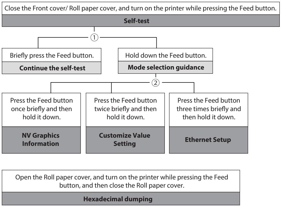
In 1 and 2, the following guidances are printed, the Paper LED flashes, and instructs the user's operations.
1. Continuing self-test guidance
Select Modes by pressing Feed Button.
Continue SELF-TEST: Less than 1 second
Mode selection : 1 second or more
2. Mode selection guidance
Mode Selection
Modes
0: Exit and Reboot Printer
1: NV Graphics Information
2: Customize Value Settings
3: Ethernet Setup
4 or more: None
Select Modes by executing following procedure.
step 1. Press the Feed button less than 1 second as many times as the selected mode number.
step 2. Press Feed button for 1 second or more.
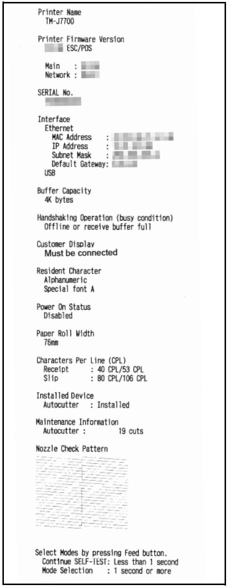
Self-test Mode
You can check the following items using the self-test.
Product name
- Firmware version
- Product serial number
- Interface information
- Buffer Capacity
- Handshaking Operation (busy condition)
- Customer Display
- Resident fonts
Power On Status
- Paper Roll Width
- Characters Per Line
- Installed device
- Maintenance counter information (number of times of autocutting)
- Nozzle Check Pattern
Self-test is printed on roll paper or slip paper.
Roll paper
Follow the steps below.
1 Close the Front cover/ Roll paper cover.
2 Turn the power on while pressing the Feed Button. Continue holding the Feed Button until the printer begins feeding roll paper.
The printer status is printed on the roll paper.
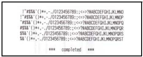
3 Briefly press the Feed button (less than one second) to continue the self-test.
The printer prints a rolling pattern on the roll paper, using the built-in character set.
After "" completed "" is printed, the printer initializes and switches to normal print mode.
Self-test print result
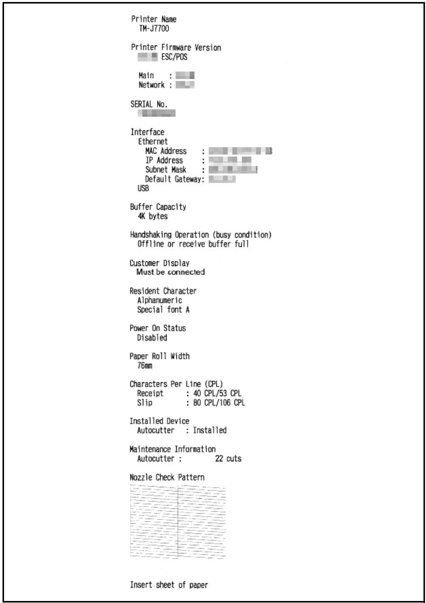
Slip paper
Follow the steps below.
NOTE
- The self-test on the slip paper will print in all columns, regardless of the slip paper width. Using a slip paper narrower than the print width of all columns will result in printing running over and making the platen dirty. Use a slip paper 85 ~mm 3.35" wide or wider.
- Set the roll paper even when performing the self-test for slip paper.
1 Close the Front cover/ Roll paper cover.
2 Turn the power on while pressing the Cleaning Button. Continue holding the Cleaning Button until the printer begins feeding roll paper.
The Cut sheet LED begins flashing.
3 Set the slip paper to begin printing the printer status on the slip paper.
After printing the current printer status, the printer ejects the slip paper and then transfers to the next slip paper insertion standby. Set the slip paper to begin the test print.
After a set of test characters, *** completed *** is printed and the self-test ends. After the initialization process, the printer enters the normal print mode.
Self-test print result
```bash
!/$$&*(+)++, -/0123456789: <=?@ABCDEFGHIJKLMNOPRSTUVWXYZ[ ] _ ' abcdefghijklmnlo'
!#$&(+)++, -/0123456789: <=?ABCDEFGHIJKLMNOPRSTUVWXYZ[ ] _ ' abcdefghklkmnop' !$$&(+)++, -/0123456789: <=?ABCDEFGHIJKLMNOPRSTUVWXYZ[ ] _ ' abcdefghklkmnop' %$()++, -/0123456789: <=?ABCDEFGHIJKLMNOPRSTUVWXYZ[ ] _ ' abcdefghklkmnop' $&&(+)++, -/0123456789: <=?ABCDEFGHIJKLMNOPRSTUVWXYZ[ ] _ ' abcdefghklkmnop' %$(*)++, -/0123456789: <=?ABCDEFGHIJKLMNOPRSTUVWXYZ[ ] _ ' abcdefghklkmnoprs
*** completed ***
NV Graphics Information Print Mode
Prints the following NV graphic information registered to the printers.
- Capacity of the NV graphics
Used capacity of the NV graphics
Unused capacity of the NV graphics
Number of NV graphics that are registered - Key code, number of dots in X direction, number of dots in Y direction to be defined.
- NV graphics data
NOTE
For details on NV graphics, see "NV Graphics Memory" on page 22.
Follow the steps below.
After running a self-test, hold down the Feed button for at least one second, and then select the Mode selection.
The Mode selection guidance is printed, and the Paper LED flashes.
2 After briefly (less than one second) pressing the Feed button once, hold it down for at least one second, to print the NV graphics information.
After information printing, the Mode selection guidance is printed again.
3 To finish, turn off the power, or select "Exit and Reboot Printer".
Customize Value Setting Mode
You can confirm and set the printer's memory switches and customized values.
| Item | Confirm | Set |
| Autocutter | ✓ | ✓ |
| Auto line feed | ✓ | ✓ |
| Paper width | ✓ | ✓ |
| Command execution during offline | ✓ | ✓ |
| LED indicator when I/F starting | ✓ | ✓ |
| Printer Model Setting Information | ✓ | - |
NOTE
- For details on the memory switches and customized values, see "Software Settings" on page 39.
- Settings for Printer Model Setting Information are specified by using the "TM-J7200/TM-J7700 Printer Model Setting Utility". See "Utilities" on page 65.
Follow the steps below.
1 After running a self-test, hold down the Feed button for at least one second to enter the Mode selection.
The Mode selection guidance is printed, and the Paper LED flashes.
2 Briefly press the Feed button three times (less than one second), hold it down for at least one second to enter the Software settings mode (Customized value setting).
The Software setting mode guidance is printed, and the Paper LED flashes.
Customize Value Settings
Modes
0:Exit
1: Print Current Settings
2: Autocutter
3: Auto Line Feed
4: Paper Width
5: Other Settings
Select Modes by executing following procedure.
step 1. Press the Feed button less than 1 second as many times as the selected mode number.
step 2. Press Feed button for 1 second or more.
3 After briefly pressing the Feed button (less than one second) for the number of times shown in the print result, hold down the button for more than one second to select the setting items.
The setting selected as the setting item, the current settings and default settings are printed.
Depending on the setting item, you may need to continue selecting the setting item before the settings are printed.
For details on setting items, see "Software Settings" on page 39.
4 Select a setting by briefly pressing the Feed button (less than one second) for the number of times applicable to the setting, and then hold down the button for more than one second to confirm your selection.
After saving the settings, the Software setting mode guidance is printed, and the Paper LED flashes.
5 To close Software setting mode, turn off the printer, or select "Exit" to return to Mode selection guidance, and then select "Exit and Reboot Printer".
NOTE
- To select 0 as the item number, hold down the Feed button until printing starts.
- If the button is pressed a number of times that is not displayed by the Setup guidance, the operation is invalid and the same guidance is printed.
Ethernet Setup Mode
This mode restores the Ethernet interface settings to the factory-default settings.
Follow the steps below.
After running a self-test, hold down the Feed button for at least one second to enter the Mode selection.
The Mode selection guidance is printed, and the Paper LED flashes.
2 Briefly press the Feed button three times (less than one second), hold it down for at least one second to enter the Interface Setup mode.
The guidance is printed.
3 Briefly press the Feed button once (less than one second), hold it down for at least one second. (Hold down the Feed button until the message of Resetting to Factory Default is printed.)
Hexadecimal Dumping Mode
In hexadecimal dumping mode, data from the host device is printed in hexadecimal numbers and characters. By comparing the print outs and the program, you can check whether or not data is being sent to the printer correctly.
NOTE
- When there are no characters that correspond to the print data, ". ." is printed.
- If you press the Feed button when there is less than one line of print data, one line is printed.
- During hexadecimal dumping mode, applications that check the printer status may not operate correctly. The printer only returns the status for the "Real-time transmission status" command.
Follow the steps below.
1 Open the Roll paper cover while the Front cover is closed.
2 While pressing the Feed button, turn on the printer. (Hold down the Feed button until the Error LED turns on.)
3 Close the Roll paper cover.
From this point, all data received by the printer is printed in the corresponding hexadecimal numbers and ASCII characters.
Example of printing in hexadecimal dumping mode:
Hexadecimal Dump To terminate hexadecimal dump, press FEED button three times. 1B21001B260240401B69.!..&. @ @i 1B25011B6334001B3031.%..c4..01 4142434445464748494AABCDEFGHJ *** completed ***
4 To close hexadecimal dumping mode, turn off the printer after printing is complete, or press the Feed button for three times.
Printing a Status Sheet
By printing a status sheet, you can check the following network-related information:
- MAC address
- Physical Layer settings
- Connection status
Network firmware version - IP address setting method
- IP address, subnet mask, default gateway
- NTP server connection information
- Time of internal settings
Printing method
Follow the procedure below to print a status sheet.
1 Check that the printer is on.
2 Open the Roll paper cover.
Hold down the Feed button for at least three seconds.
Paper LED starts flashing.
4 Close the Roll paper cover. The status sheet is printed. After printing, the printer returns to the standard mode.
*** Ethernet Interface ***
Ethernet Status
MAC Address

Physical Layer
: Auto-negotiation
Link Status
:Connect
Network
Soft Version

TCP/IP
Acquiring
:Auto
IP Address

Subnet Mask

Default Gateway

APIA
: Disable
ARP+Ping
:Enable
Other Status
TimeServer
Invalid
Date/Time
:2016/01/01 00:00:00
EpsonNet Config (Web Version)
This section explains items that can be displayed in the Web application EpsonNet Config (Web version) built into the TM-J7200/TM-J7700, as well as items that can be set.
Information Menu
On the Information menu, you can check the following settings. For the details of each protocol or the settings other than the Information menu, check the Configuration menu.
Basic Information
You can check the items below.
(Administrator name, installation location, MAC address, software version, printer model name, printer status)
TCP/IP
You can confirm TCP/IP protocol IP address settings.
SNMP
You can confirm SNMP protocol settings.
Bonjour
You can confirm Bonjour protocol settings.
Time Setting
You can confirm SNTP protocol time server settings.
Timeout
You can confirm LPR/Port9100 protocol Timeout duration settings.
Configuration Menu
On the Configuration menu, you can check and set the following items.
Ethernet
You can check and set the communication standard.
(Auto / 10Base-T Half Duplex / 10Base-T Full Duplex / 100Base-Tx Half Duplex / 100Base-Tx Full Duplex)
Security
SSL/TLS
You can check and set the SSL/TLS.
- Selection of the server certificate type (Self-Signed Certificate / CA-Signed Certificate1 / CA-Signed Certificate2 / CA-Signed Certificate3)
- Encryption strength setting (Medium / Low / High)
- Setting for automatic redirect from HTTP to HTTPS (Enable / Disable)
- Confirmation of each certificate
Authentication
Certificate List
You can check the following items for certificates.
- Self-Signed Certificate setting
- CA-Signed Certificate settings 1 to 3
- CA Certificate settings 1 to 10
Certificate Import
You can check and set the following items for certificate imports.
- File format settings (PEM/DER Certificate / Password Protected PKCS#12 Certificate)
- File name input
-
Password input
-
If you import and select an invalid certificate, you will no longer be able to start up EpsonNet Config (Web version).
In that case, use TM-J7200 TM-J7700 Utility to select a certificate other than the invalid one (for example, a Selfsigned Certificate), and import the correct certificate with EpsonNet Config (Web version) again.
TCP/IP
IP v4 Address
This sets the IP address when setting the manual.
- Setting for IP address acquisition method (Manual / Auto)
- IP address setting
- Subnet mask address setting
- Default gateway address setting
- APIPA setting (Enable / Disable)
- ARP+Ping setting (Enable / Disable)
DNS/DDNS
This sets the DNS server address (IPv4).
- Setting for automatic acquisition of the DNS server address (Disable / Enable)
DNS server address setting
This sets the host name and domain name.
- Setting for automatic acquisition of the host name and domain name (Disable / Enable)
- Host name input
- Domain name input
- Setting of the function for registering the network I/F address in the DNS server (Disable / Enable)
SNMP
Community
This sets the community name used in notifications. You can set up to 16 ASCII characters.
- Read Only community name fixed as "public" * Cannot be changed
- Read/Write community name input
IP Trap
This sets the IP trap.
IP Trap1
- Trap setting (Disable / Enable)
- Trap address setting
- Community name input
IP Trap2
- Trap setting (Disable / Enable)
- Trap address setting
- Community name input
Bonjour
This sets Bonjour.
- Bonjour setting (Disable / Enable)
- Name input for when using Bonjour *
- Printer name setting for when using Bonjour *
- Installation location input
- You can use upper and lower case alphabet characters, numerals and hyphens, however, only use upper and lower case alphabet characters for the initial character.
Time Setting
You can check and set the time server.
- Use of time server (Disable / Enable)
- Time server address setting
- Time setting for refresh interval (Can be set between 1 min to 10,080 min) - Default is 60 min.
- Time difference settings
Timeout
This sets the timeout time for printing.
- LPR time-out setting - Default is 90 sec.
- RAW (Port9100) time-out setting - Default is 90 sec.
Certificate Import
NOTE
Enable the time server when using a certificate.
Make the following settings in the Authentication - Certificate Import menu.
1 Set the file type of certificate.
2 Specify the certificate file to import.
3 If the file type of certificate is PKCS#12, enter the password.
4 Click [Import].
Application Development Information
This chapter describes how to control the printer and gives information useful for printer application development.
Controlling the Printer
The printer supports the following command systems:
- ESC/POS
Users can control the printer by using the aforementioned commands, or the following development kits or drivers.
EPSON OPOS ADK
- EPSON OPOS ADK for .NET
- EPSON JavaPOS ADK
- EPSON Advanced Printer Driver
EPSON TM Virtual Port Driver
ESC/POS
ESC/POS is the Epson original printer command system for POS printers and customer display. With ESC/POS commands, you can directly control all the TM-J7200/TM-J7700 printer functions, but detailed knowledge of printer specifications or combination of commands is required, compared to using drivers and applications.
For detailed information about ESC/POS commands, see the Product Specifications. Product Specifications is available after contracting the non-disclosure agreement with Epson. For details, please contact the selling agency.
Software
The following software is provided for application development.
Development Kit
| Software | Description |
| EPSON OPOS ADK | This OCX driver can control POS peripherals using OLE technology. *Because controlling POS peripherals with original commands is not required on the application side, efficient system development is possible. |
| EPSON OPOS ADK for .NET | The OPOS ADK for .NET is a POS industry standard printer driver compatible with Microsoft POS for .NET. It allows you to develop applications that are compatible with the UPOS (Unified POS) specification. When developing applications, use a separate development environment such as Microsoft Visual Studio .NET. |
| EPSON JavaPOS ADK | JavaPOS is the standard specification which defines an architecture and device interface (API) to access various POS devices from a Java based system. Using JavaPOS standard API allows control with Java based applications of functions inherent to each device. A flexible design with Java language and JavaPOS enables many different types of computer systems, such as stand alone or network configuration, to use a same application. You can use JavaPOS to build applications and drivers independently of platforms. This allows flexible configurations using thin clients to meet the system requirements. |
*: OLE technology developed by Microsoft divides software into part blocks. The OPOS driver is presupposed to be used with a development environment, such as Visual Basic, unlike ordinary Windows printer drivers. It is not a driver to be used for printing from commercial applications. You can acquire documents regarding the UnifiedPOS from the following link. https://nrf.com/resources/retail-technology-standardst/unifiedpos
Drivers
| Software | Description | Operating environment |
| EPSON Advanced Printer Driver | In addition to ordinary Windows printer driver functions, this driver has controls specific to POS. The Status API (Epson original DLL) that monitors printer status and sends ESC/POS commands is also attached to this driver. | Windows |
| EPSON TM Virtual Port Driver | This is a serial/parallel-USB/LAN conversion driver to make an Epson TM/BA/EU printer connected via USB or LAN accessible from a POS application through a virtual serial or parallel port. It allows you to directly control devices connected via USB or LAN with ESC/POS commands without making changes in the POS application that controls devices connected via a serial or parallel interface. | Windows |
Utilities
| Software | Description | Operating environment |
| TM-J7200 TM-J7700 Utility | A utility for checking and changing various printer settings. Use this utility to:Check the current settingsStoring LogosSet printing controlSet IP AddressSet DNSSet CertificateSet SSL/TLSSet EthernetSet SNMPSet TimeoutSet BonjourSet Time ConfigurationSet IP/Port FilterSet Administrator Name and LocationSave/restore settingsTest operation | Windows |
| Deployment Tool | Use to make network and printer settings simultaneously. Allows you to make settings efficiently at the time of introducing TM printers for the first time, or when configuring multiple TM printers at the same time. | Windows |
| Monitoring Tool | Use to check a list of status for the Epson printers connected to the network.You can also update certificates for multiple printers used for WPA-Enterprise in a batch. | Windows |
| TM-J7200/TM-J7700 Printer Model Setting Utility | This tool allows you to change the model name for the TM-J7200 to TM-J7000II and TM-J7000, and TM-J7700 to TM-J7500II and TM-J7500. | Windows |
| TM-J7200 TM-J7700 Firmware Updater | Use this tool to update the printer's firmware.An executable file and the firmware are packaged together. | Windows |
Download
You can obtain software and manuals from one of the following URLs.
For customers in North America, go to the following web site and follow the on-screen instructions.
http://www.epson.com/support/
For customers in other countries, go to the following web site:
http://download.epson-biz.com/?service=pos
Turning off the Printer without Using the Power Switch
If turning off the printer without using the power switch, send the command to execute the power-off sequence. If the power-off sequence is not executed, cleaning will be performed the next time the printer is turned on, thus consuming ink, and if the printer is not used for over two weeks, the nozzles may become clogged and will not recover.
Printing Barcodes/2-dimensional Symbols
To print barcodes/2-dimensional symbols with this product, the following methods are available:
- Printing after preparing graphic data of the barcode/2-dimensional symbol using the application.
- Printing by using the barcode fonts installed on the printer. For details about how to use the fonts, refer to the printer driver manual.
Notes on printing barcodes
When printing barcodes with this product, note the following points:
- We recommend using the barcodes with the height of 33mm1.30" or less. If the height of barcodes is more than 33mm1.30" , quality for scanning barcodes may decline. After printing barcodes, make sure they can be scanned correctly using a barcode scanner.
- When scanning barcodes, be aware that the recognition rate may vary based on the paper material and the performance of the scanner.
- When printing barcodes, we recommend also using HRI characters.
- Because the recognition rate for barcodes may vary based on the performance of the barcode reader, considerations should be taken so that the system can also be input HRI characters for processing if the barcode cannot be recognized.
- If printing a ladder barcode, it is recommended to set the minimum module width to 0.423mm 0.02" or the element width to 3 or more.
- Do not use a ladder barcode on a slip paper.
- A quiet zone (left or right-side space area, determined by the bar code specifications) must be ensured by the user for barcode printing.
Notes on printing 2-dimensional symbols
When printing 2-dimensional symbols with this product, note the following points:
- We recommend using the 2-dimensional symbols with the height of 33mm1.30" or less. If the height of symbols is more than 33mm1.30" , quality for scanning symbols may decline. After printing 2-dimensional symbols, make sure they can be scanned correctly using a barcode scanner.
- When printing 2-dimensional symbols, it is recommended to set the height of 1 step of the symbol to 3-5 times the width of one module, and the total height of the code should be about 5mm0.20" or more.
- When using a page mode that includes a 2-dimensional symbol, the printer uses normal mode and unidirectional direction for all passes that include the 2-dimensional symbol. Because the print density changes midway, we recommend printing all pages in normal mode.
- If printing a 2-dimensional symbol with a 90^ or 270^ orientation, it is recommended to set the minimum module width to 0.423 ~mm 0.017" or the module width to 3 or more.
- The PDF417 quiet zone (left and right, upward and downward space areas for symbols determined by the PDF417 symbol specifications) must be ensured by the user.
Handling
This chapter describes basic handling of the printer.
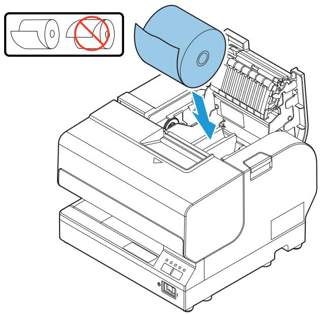
Installing/Replacing the Roll Paper
CAUTION
- Be sure to use roll paper that meets the specifications.
- Do not use thermal paper.
- Be careful not to insert your fingers into the paper exit. The cutter blade is installed inside the paper exit and you might be injured.
NOTE
Do not open the Roll paper cover during printing or paper feeding.
Follow the procedure below to install or replace paper:
1 Make sure the printer is turned on.
2 Open the Roll paper cover by pressing the cover open button.

3 Remove the used roll paper core if there is one.
4 Put the roll paper inside the printer in the correct direction as shown in the illustration below.
Before closing the cover, pull out the leading edge of the roll paper and align the mark as shown in the illustration below.
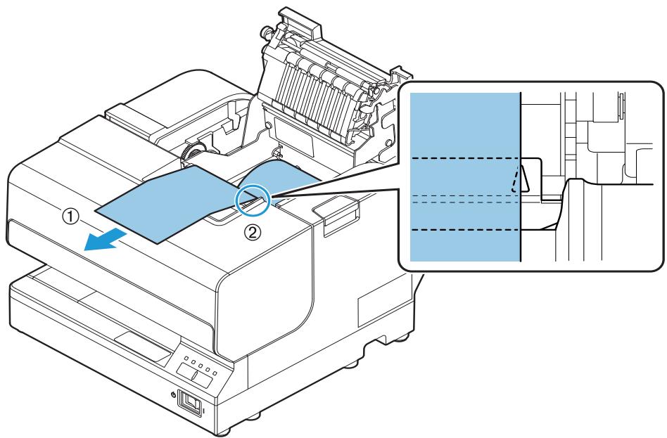
6 Close the Roll paper cover.
The printer will automatically feed the roll paper to remove any slack in the paper.
Notes on Use
- The emergency cutter on the roll paper exit section is only for cutting paper. Be careful, as touching the blade may result in injury.
- When the Roll paper cover is open, it is possible to touch the fixed blade and revolving blade of the autocutter. The part is only for cutting paper. Be careful, as touching the blade may result in injury.
- The paper ejection slot contains the cutter blades. Do not insert your fingers, as doing so may result in injury.
- When the Roll paper cover is open, do not touch the plastic gears on the left side, and do not apply a force that may disfigure them.
- If a paper jam occurs, do not forcefully pull the paper or use tools, but open the Roll paper cover and manually remove the paper.
- Do not open the cover during operation. (It may cause a paper jam.)
Inserting Slip Paper
NOTE
- Be sure the paper is flat, without curls, folds, or wrinkles.
- Use only single sheet paper. Do not insert any multiple sheet paper, as this may cause a paper jam.
- Pressure sensitive copy paper cannot be used because the printer is an inkjet printer.
- Roll paper must be installed evenly for printing on slip paper in order to prevent paper jams.
Follow the procedure below to insert slip paper:
1 Make sure the printer is turned on.
NOTE
Confirm that the Cut sheet LED is turned off or flashing continuously when inserting slip paper.
2 Set the paper so that the right edge of the paper contacts the paper guide on the right and insert the slip paper. Refer to the label affixed to the printer.
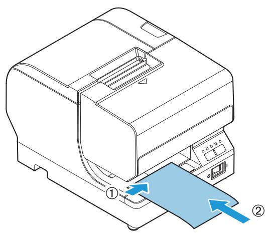
TM-J7200
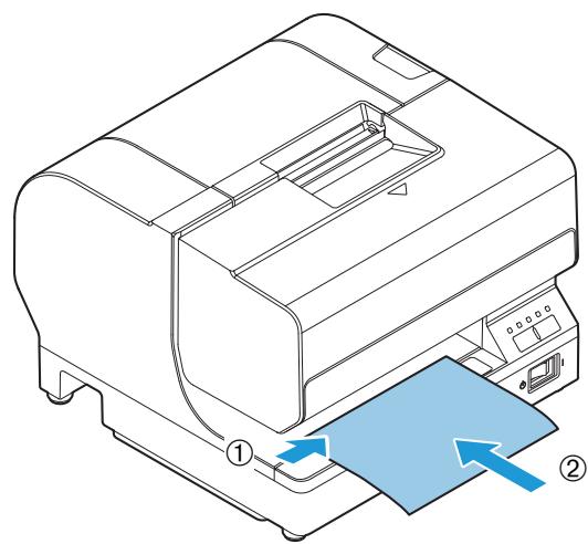
TM-J7700
3 The Cut sheet LED turns on when slip paper is being printed. After printing has been completed and the slip paper has been discharged, the Cut sheet LED repeats a double-reflecting pattern.
NOTE
If the next print data is sent before printed paper is removed, the printer goes offline, causing the Error LED to turn on.
4 Remove the slip paper. After approximately one second, the status of the Cut sheet LED changes as follows.
| Next print data | LED status |
| If there is no next data | OFF |
| If there is next data | Flashing |
NOTE
Confirm that the Cut sheet LED is not repeating a double-flashing pattern when inserting the next slip paper.
If the next slip paper is inserted while the Cut sheet LED is repeating the double-FLASHING pattern, Removal for Slip ejection is not cancelled even if the printed paper is removed. For this reason, printing will not start even if the next print data arrives. When this occurs, remove the inserted paper, and confirm that the Cut sheet LED is turned off or flashing continuously before inserting the paper again.
Notes on Use
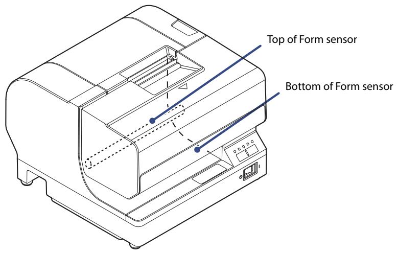
- Be sure to align slip papers with the right-side guide and form stopper when setting them. If the paper is inserted at an angle, the slip detection (TOF: Top of Form, BOF: Bottom of Form sensors) cannot operate properly and the paper cannot be clamped. Also, let go of the paper quickly once it is clamped by the printer.
- Remove the printed slip paper and then set the next slip paper for printing. If you do not remove the printed slip paper first, the printer cannot recognize that the sheet has been removed and does not move onto the next operation.
- The slip section of this printer uses ink jet printing, and cannot be used with pressure-sensitive forms.
- The slip section of this printer is only for use with single-sheet paper. Do not insert multi-part forms, as they may cause paper jams.
Installing/Replacing the Ink Cartridge
Install/Replace the ink cartridge by following the procedure below.
1 Make sure the printer is turned on.
2 Make sure the Ink LED is on or flashing.
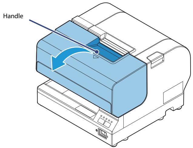
3 Pull the handle to open the Front cover
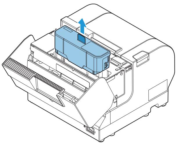
4 During replacement, remove the used ink cartridge.

Do not put your fingers inside the ink cartridge compartment or you may be injured by a sharp or protruding part.
5 Shake the ink cartridge package three or four times before opening it.
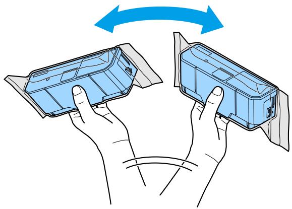
6 Insert a new ink cartridge from the top and push it firmly but gently until it clicks into place.
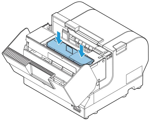
7 Push down the tab in the direction of the arrow before closing the Front cover.
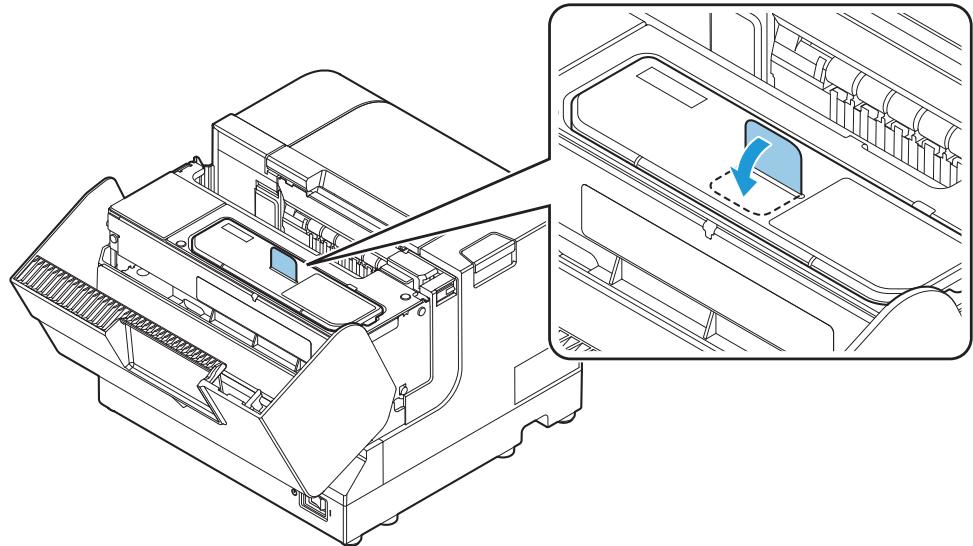
8 Close the Front cover.
The Ink LED will now turn off.
When the ink cartridge is installed for the first time, the Power LED flashes and initial ink charging starts.
CAUTION
Never open any cover on the printer or turn off the printer during ink charging (while the Power LED is flashing). Doing so during ink charging will consume a large amount of ink, which may require replacement of the ink cartridge before completion of charging.
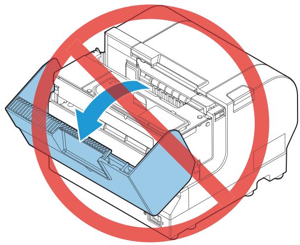
NOTE
The ink cartridge included in the product package is used for initial ink charging. The printer uses ink to prepare for printing when the ink cartridge is installed for the first time.
It takes at least two minutes to charge ink. The ink charging time varies depending on the conditions.
When ink charging completes, the Power LED changes from flashing to on.
Perform a test print to check if printing is performed properly. (See "Test Printing" on page 81.)
Notes on Use
- Be sure to keep the ink cartridge out of the reach of children. Be sure not to swallow any ink.
- Do not disassemble the ink cartridge or attempt to refill or replace the ink. Doing so could cause ink to leak or damage the printer.
- Be careful when handling the ink cartridge, as any ink that gets on your clothing may cause a permanent stain.
- Do not press on the supply section of the ink cartridge, as doing so may cause ink to leak.
- Do not touch the ink supply section of an ink cartridge that has been installed then removed, as some ink might be stuck on it. Also, be careful where you place it.
- Do not touch the plate on the ink cartridge. The ink cartridge may no longer operate properly.
- The ink cartridge holder in the printer which stores the ink cartridge contains a needle for supplying ink to the printer, which has ink on it. Do not insert your finger or the like, as it will get dirty.
-
Do not remove the ink cartridge from the printer except when replacing it.
-
Unnecessarily opening or closing the Front cover except for replacement causes unnecessary ink consumption and can significantly harm the print life of the ink cartridge.
- Use up an ink cartridge within half a year of installing it. When a significant amount of time passes since it was opened, the ink cartridge may not be used to print properly.
- Use up the ink cartridge by the date printed on its individual box or on the ink cartridge itself.
- The ink inside the ink cartridge may freeze if left at temperatures of -20^ (-4.0^) or lower, but it can be used after thawing and reaching 10^ (50^) or higher.
- When printing on water-repellent paper such as art paper, the ink may dry very slowly and smear. Use paper that does not cause smearing.
- Do not transport an ink cartridge that is in use by itself, as transporting it while it is not installed in the printer may cause ink to leak.
- Do not apply strong shocks or vibrations to the ink cartridge.
- Ink life varies based on the printer usage and the printed contents.
- We recommend using genuine Epson ink cartridges. Using ink cartridges not manufactured by Epson may cause the product to not function properly, such as causing unrecoverable damage to the printer or print quality.
- Be sure to use ink cartridges with the specified model number. Using ink cartridges other than those specified may cause ink leaks or negatively affect printing.
- Do not apply petroleum benzine, paint thinner, toluene, or ketone-based solvents to the ink cartridge, as they may cause deformation or damage to the plastic components.
- Dispose of ink cartridges in accordance with all national and local laws, ordinances, and regulations.
- Because it takes a long time (approx. 2 minutes) to complete the ink loading when beginning to use the printer (initial loading), never turn off the power during loading (when the Power LED is flashing, until it turns on). (Be careful as turning off the power during ink loading causes the ink loading process to be performed again from the start, resulting in a significant waste of ink.)
- Ideally, the ink loading when beginning to use the printer (initial loading) should be performed with the printer itself (without performing an interface reset).
- Do not perform unnecessary manual cleaning other than when print problems occur.
- While the Power LED is flashing, the printer is performing cleaning or ink loading. Do not open the Roll paper cover or turn off the power switch.
Removing Jammed Paper
CAUTION
When a paper jam occurs, never pull out the paper forcibly.
For roll paper
Follow the steps below if the roll paper is jammed.
1 Turn off the printer.
2 Open the Roll paper cover.
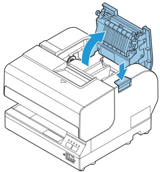
3 Remove the paper causing the paper jam.
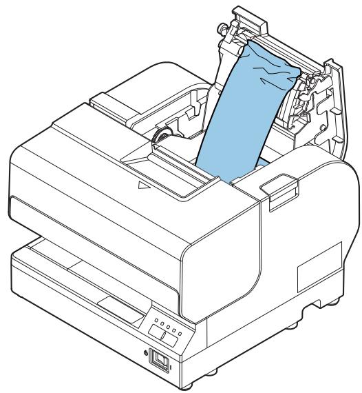
4 Set the roll paper again and close the cover.
For slip papers
Follow the steps below if the slip paper is jammed.
1 Turn off the printer.
2 Open the Front cover.
3 Remove the paper causing the paper jam.
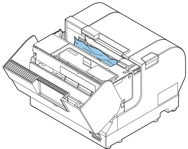
4 Close the Front cover.
Test Printing
You can perform printer status printing using the self-test to check if any print errors, such as dot drop-outs, are occurring.
You can use the nozzle check pattern which is printed to check whether the nozzle is clogged.
Follow the procedure below to perform the self-test.
1 Make sure the printer is turned off.
2 Turn the power on while pressing the Feed Button. Continue holding the Feed Button until the printer begins feeding roll paper.
The printer status is printed on the roll paper.
3 Check the printed nozzle check pattern.
If the pattern is printed normally, all the lines are printed properly as shown in the left figure below.
Perform head cleaning if there are any broken or unprinted lines due to nozzle clogging, as shown in the right figure below.
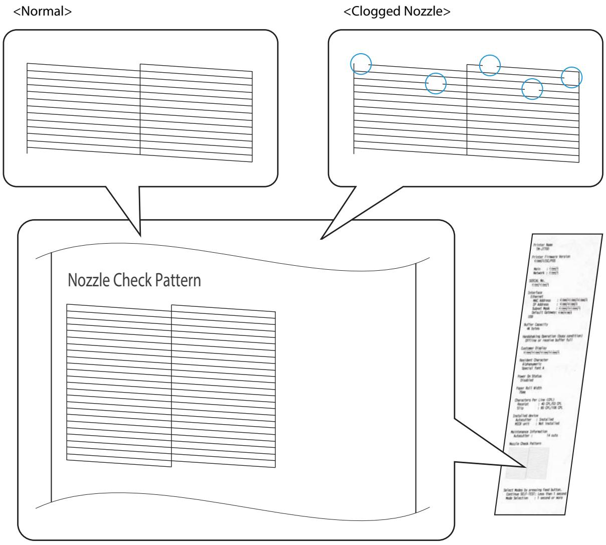
Cleaning the Printer
Cleaning the Printer Case
Be sure to turn off the printer, and wipe the dirt off the printer case with a dry cloth or a damp cloth. Be sure to unplug the AC cable while cleaning.

Never clean the product with alcohol, benzine, thinner, or other such solvents.
Doing so may damage or break the parts made of plastic and rubber.
Cleaning the Print Head
Perform head cleaning if the print result is not normal as shown in the illustration below.
ABC ABC

- Head cleaning takes one to two minutes. Do not open any cover or turn the power off during head cleaning.
- Do not press the Cleaning button unless there is a problem with print quality. Unnecessary head cleaning will waste ink.
Follow the procedure below to perform head cleaning.
1 Make sure the printer is turned on.
2 Press the Cleaning button more than 3 seconds. The Power LED flashes and head cleaning begins.
When head cleaning is complete, the Power LED turns off and the printer can perform normal printing. Perform a test print to check if printing is performed properly. (See "Test Printing" on page 81.)
Preparing for Transport
Follow the procedure below to transport this printer.
1 Remove the roll paper.
NOTE
Leave the ink cartridge in the printer. Transporting the printer with the ink cartridge removed can result in dot dropout or ink adhering to the inside of the case.
2 Turn off the printer.
3 Check that the Power LED is off.
4 Disconnect the power cable and all other cables.
5 Attach the protective materials and affix tape as shown in the figure below. TM-J7200
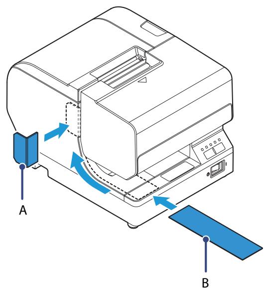
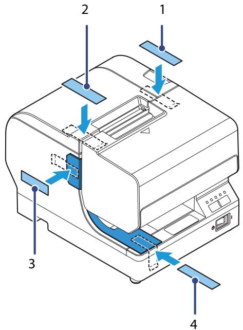
TM-J7700
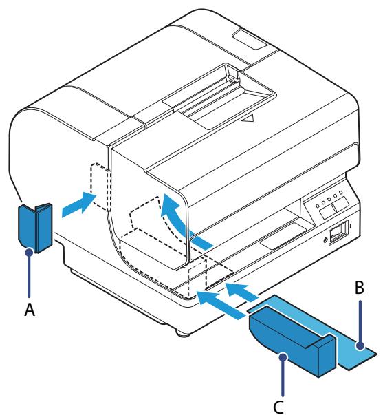
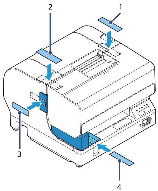
6 Wrap the printer with protective cushioning material to prevent any impacts during transport.
Keep the printer upright and horizontal while packing and transporting it.
NOTE
Reshipping it can result in dot dropout. Perform head cleaning if dot dropout occurs. (See "Cleaning the Print Head" on page 82.)
Troubleshooting
This chapter describes the actions to take when a trouble occurs.
| Trouble | Reference |
| Error LED is on/flashing | See page 86. |
| Ink LED is on/flashing | See page 87. |
| Print quality problem | See page 88. |
| When slip paper is set, paper is discharged, resulting in an error | See page 89. |
| Setting slip paper does not start printing | See page 90. |
| Paper jam | See page 90. |
| Printing from the computer is disabled/Printing was suddenly disabled | See page 91. |
| Power does not turn on | See page 92. |
| "A maintenance part must be replaced." is printed. | See page 92. |
Error LED is On/Flashing
Automatically Recoverable Errors
| Error | Error description | Error LED flash code | Recovery measure |
| Roll paper cover open error (When automatic recovery is selected*) | The Roll paper cover is open during roll paper print operation. | LED ON LED OFF | Automatically recovers when the Roll paper cover is closed. |
*: Selected by the memory switch.
Recoverable Errors
| Error | Error description | Error LED flash code | Recovery measure |
| Roll paper cover open error (When possible error recovery is selected*) | The Roll paper cover is open during roll paper print operation. | LED ON LED OFF Approx. 320 ms | Close the Roll paper cover, turn the power on to recover. |
| Autocutter error | The autocutter does not operate properly. | LED ON LED OFF Approx. 320 ms | Remove the jammed paper or foreign matter in the printer, close the Roll paper cover, turn the power on to recover. |
| Carriage error | The carriage home position cannot be detected. Alternatively, the carriage does not operate properly. | LED ON LED OFF Approx. 320 ms | Remove the jammed paper or foreign matter in the printer, close the Front cover, turn the power on to recover. |
| Cut sheet error | The cut sheet cannot be fed. | LED ON LED OFF Approx. 320 ms | Remove the jammed paper or foreign matter in the printer, close the Front cover, turn the power on to recover. |
*: Selected by the memory switch.
Unrecoverable Errors
| Error | Error description | Error LED flash code |
| Unrecoverable errors | An unrecoverable error has occurred. CAUTION: Turn off the power immediately when an unrecoverable error occurs. If the same error occurs again even after turning the power back on, contact qualified service personnel for advice. | LED ON → Approx.320 ms LED OFF → |
Ink LED is On/Flashing
Check the Ink LED.
Ink LED is flashing
| Cause | Solution and reference |
| Ink is low. | Prepare an ink cartridge for when replacement is required. |
Ink LED is on
| Cause | Solution and reference |
| An ink cartridge is not installed. | Install an ink cartridge. |
| It is time to replace the ink. Cannot print. | Replace an ink cartridge. |
Print Quality Problem
Identify the cause from the print examples below and solve the problem.
| Print example | Solution and reference |
| ABC | Missing dots are occurring. Perform head cleaning. (See "Cleaning the Print Head" on page 82.)If the problem is not solved, ask for repair. |
| ABC |
Misaligned print position
| Cause | Solution and reference |
| The slip paper is set in a incorrect position. | Check whether the slip paper is inserted straight along the paper guide. If the paper is inserted at an angle, misalignment may occur in the print result. |
Print result on slip paper is skewed
| Cause | Solution and reference |
| The slip paper is inserted at an angle. | Check whether the slip paper is inserted straight along the paper guide. If the paper is inserted at an angle, misalignment may occur in the print result. |
Missing print data
| Cause | Solution and reference |
| The paper being used does not match the printer driver settings. | Check the printer driver settings. |
Paper gets dirty/stained with ink
| Cause | Solution and reference |
| If any foreign matter adheres to the head, the paper may get dirty. | Perform manual head cleaning. Press and hold the Cleaning button for 3 seconds or longer to start head cleaning. |
When slip paper is set, paper is discharged resulting an error
| Cause | Solution and reference |
| The paper being used does not match the printer driver settings. | Check the printer driver settings. |
Setting slip paper does not start printing
Check the Cut sheet LED.
Cut sheet LED is flashing continuously
Waiting for insertion of slip paper.
| Cause | Solution and reference |
| The slip paper is set in a incorrect position. | Check whether the slip paper is inserted straight along the paper guide. If the paper is inserted at an angle, misalignment may occur in the print result. |
Cut sheet LED repeats a double-reflecting pattern
| Cause | Solution and reference |
| A new slip paper was inserted before the printed slip paper was removed. | Remove both the printed slip paper and the new slip paper. When the cut sheet LED stops a double-flashing pattern, insert the new slip paper. |
Cut sheet LED is off
| Cause | Solution and reference |
| Roll paper is set as the paper source. The slip paper is not ready for printing. | Check the application and change the paper source to slip paper. |
| Not connected to the computer. | Check the interface cable. |
Paper jam
| Cause | Solution and reference |
| Slip paper jam | Open the Front cover and remove the paper. |
| Roll paper jam | Open the Roll paper cover and the Front cover and remove the paper. |
Printing from the computer is disabled/Printing was suddenly disabled
Printer is offline
Remove the cause of going offline.
See "Online and Offline" on page 19.
Reconnect the printer and the computer
1 Check the cable connection.
Check whether the power/USB/wired LAN cables are properly connected.
2 Reconnect all devices.
For USB connection
- Disconnect the USB cable and then connect it again.
- When the computer has multiple USB connectors, reconnect the cable to another connector. For wired LAN
- As operation of a device connected with a wired LAN may be unstable, restart the network.
- Turn off all devices.
- Wait for approx. 10 seconds, and turn on the network device, computer, and printer in this order.
NOTE
When there is a network administrator, follow his/her instructions.
3 Check whether data is sent from the computer to the printer.
Check installation of printer driver
Check whether the required software and applications are installed on the computer.
For details about how to check installation of printer driver, refer to the manual for each printer driver.
Power does not turn on
Check whether the power cable and AC adapter are properly connected to the printer and outlet.
"A maintenance part must be replaced." is printed
| Cause | Solution and reference |
| The message shown below is printed each time the printer is turned on. Caution: A maintenance part must be replaced. Contact qualified service personnel. | A maintenance part (pump unit, ink supply unit, or waste liquid absorber) is near the end of its service life. Contact qualified service personnel. |
Appendix
Specifications of Interface and Connector
USB Interface
USB interface connector
USB type-B connector
USB transmission specifications
USB function
| Overall specifications | According to USB 2.0 specifications | |
| Transmission speed | USB Full-Speed (12 Mbps) | |
| Transmission method | USB bulk transmission method | |
| Power supply specifications | USB self power supply function | |
| Current consumed by USB bus | 2 mA | |
| USB packet size (with full-speed connection) | USB bulk OUT (TM) | 64 bytes |
| USB bulk IN (TM) | 64 bytes | |
| USB device class | USB vendor-defined class. | |
USB descriptor
| USB vendor-defined class | ||
| Vendor ID | 04b8h | |
| Product ID | 0202h | |
| String Descriptor | Manufacturer | Epson |
| Product | TM-J7200 / TM-J7700 | |
| Serial number | Character string based on the product serial number | |
Ethernet Interface
Communication specifications
10BASE-T/100BASE-TX
Support protocols
| Protocols | Usage |
| IP, ARP, ICMP, UDP, TCP | Basic communication protocols |
| LPR, TCP Socket Port | Printing protocols |
| HTTP/HTTPS | Used in EpsonNet Config (Web version) |
| SNMP, ENPC | Used in setting and monitoring |
| DHCP, APISA | Used in automatic setting for the IP address and so on |
Product Specifications
| Item | Specification | ||
| Model number | TM-J7200 | TM-J7700 | |
| Printing method | Serial inkjet Dot Matrix Method Single color printing (Black) | ||
| Paper feed | Unidirectional friction feed | ||
| Paper feed speed | 282 mm/s {11.1"/s} (continuous paper feeding with the Feed button) | ||
| Cutting method | Circular cut | ||
| Interface | Ethernet | × 1 10BASE-T/100BASE-TX | |
| USB | × 1 USB 2.0 Full speed, Type B | ||
| Barcode printing | UPC-A, UPC-E, JAN13 (EAN13), JAN8 (EAN8), CODE39, ITF, CODABAR (NW7), CODE93, CODE128, GS1-128, GS1 DataBar Omnidirectional, GS1 DataBar Truncated, GS1 DataBar Limited, GS1 DataBar Expanded | ||
| 2-dimensional symbol printing | PDF417, QR code, MaxiCode, 2D GS1 DataBar, Composite Symbology, Aztec Code, DataMatrix (2D Mailmark Type 9, Type 7, Type 29) | ||
| Power supply | Dedicated AC adapter PS-180 (model: M159E) DC 24 V ± 7 % | ||
| Power consumption * | Operating | Approx. 15.9 W | |
| Standby | Approx. 1.8 W | ||
| Current consumption | Input current from the AC adapter Average: Approx. 1.8 A | ||
| Life | Printer mechanism | Receipt: 15,000,000 lines Slip: 5,000,000 lines | |
| Print head | 3,700,000,000 shots / nozzle (1 shot / dot) | ||
| Autocutter | 1,500,000 cuts | ||
| MTBF | 180,000 hours | ||
| MCBF | 50 million lines | ||
| Temperature/humidity | During operation | 10 to 35°C {50 to 95°F}20 to 80% RH (No condensation | |
| During storage | Ink cartridge installed:-20 to 40°C [-4 to 104°F]20 to 85% RH (No condensation)(At -20°C [-4°F] or 60°C [140°F]: up to 12 hours) | ||
| Ink cartridge not installed:-20 to 60°C [-4 to 140°F]5 to 85% RH (No condensation)(At -20°C [-4°F] or 60°C [140°F]: up to 120 hours) | |||
| Overall dimensions (W × D × H) | 195 × 260 × 188 mm{7.68 × 10.24 × 7.40"} | 251 × 260 × 188 mm{9.88 × 10.24 × 7.40"} | |
| Weight | Approximately 5.1 kg {11.24 lb}(including the ink cartridge) | Approximately 5.8 kg {12.79 lb}(including the ink cartridge) | |
*: According to Epson's operating conditions.
Printing Specifications
Characters per Line and Printable Area for Roll Paper
| Paper width (mm) | 57.5 | 69.5 | 76 | 82.5 | ||
| Print dot count (dots) * | 1200 (360) | 1440 (432) | 1600 (480) | 1706 (512) | ||
| Print width (mm) | 50.8 | 61 | 67.7 | 72.2 | ||
| Characters per line | Font A | 30 | 36 | 40 | 42 | 15 cpi |
| Font B | 40 | 48 | 53 | 56 | 20 cpi | |
| Font A, when increasing number of lines | 32 | 39 | 43 | 46 | 16.3 cpi | |
| Font B, when increasing number of lines | 45 | 54 | 60 | 64 | 22.5 cpi | |
| Special Font A | 24 | 28 | 32 | 34 | 12 cpi | |
*: With 600 dpi. Parentheses indicate value for 180 dpi.
[cpi: characters per inch (25.4 mm)]
Characters per Line and Printable Area for Slips (TM-J7200)
| Print dot count (dots) * | 1920 (576) | ||
| Right margin (mm) * | 4.3 | ||
| Print width (mm) | 81.3 | ||
| Characters per line | Font A | 48 | 15 cpi |
| Font B | 64 | 20 cpi | |
| Font A, when increasing number of lines | 52 | 16.3 cpi | |
| Font B, when increasing number of lines | 74 | 22.5 cpi | |
| Special Font A | 38 | 12 cpi | |
*: With 600 dpi. Parentheses indicate value for 180 dpi.
[cpi: characters per inch (25.4 mm)]
Characters per Line and Printable Area for Slips (TM-J7700)
| Print dot count (dots) * | 3200 (960) | 3257(977) | |||
| Right margin (mm) * | 4.3 | 2.0 | |||
| Print width (mm) | 135.6 | 137.8 | |||
| Characters per line | Font A | 80 | 15 cpi | 81 | 15 cpi |
| Font B | 106 | 20 cpi | 108 | 20 cpi | |
| Font A, when increasing number of lines | 87 | 16.3 cpi | 88 | 16.3 cpi | |
| Font B, when increasing number of lines | 120 | 22.5 cpi | 122 | 22.5 cpi | |
| Special Font A | 64 | 12 cpi | 65 | 12 cpi | |
*: With 600 dpi. Parentheses indicate value for 180 dpi.
[cpi: characters per inch (25.4mm)]
General Print Speed
| Print control mode | Font | Roll paper width TM-J7200/ TM-J7700 (mm) | Slip paper | |||||
| 57.5 | 69.5 | 76 | 82.5 | TM-J7200 | TM-J7700 | |||
| Normal | Font A (6 lpi) | (lps) | 24.8 | 23.8 | 23.2 | 22.8 | 19.8 | 16.9 |
| Font B (8 lpi) | (lps) | 33.1 | 31.7 | 30.9 | 30.4 | 26.4 | 22.6 | |
| Graphics | (mm/s) | 107 | 102 | 100 | 98 | 85 | 73 | |
| High-speed | Font A (6 lpi) | (lps) | 24.8 | 23.8 | 23.2 | 22.8 | 19.8 | 16.9 |
| Font B (8 lpi) | (lps) | 33.1 | 31.7 | 30.9 | 30.4 | 26.4 | 22.6 | |
| Graphics | (mm/s) | 10.7 | 102 | 100 | 98 | 85 | 73 | |
| Economy | Font A (6 lpi) | (lps) | 24.8 | 23.8 | 23.2 | 22.8 | 19.8 | 16.9 |
| Font B (8 lpi) | (lps) | 33.1 | 31.7 | 30.9 | 30.4 | 26.4 | 22.6 | |
| Graphics | (mm/s) | 10 7 | 102 | 100 | 98 | 85 | 73 | |
[lpi: lines per inch (25.4mm)]
[lps: lines per second]
NOTE
- Print speed when continuously printing for all lines without cleaning and without character styles.
- The print speed may decrease due to the transmission status or the combination of commands.
- If the line spacing of the print data is smaller than the font height, the print speed may decrease due to printing one line at a time.
Print control mode
| Print control mode | Number of carriage passes * | Vertical resolution [dpi] | Horizontal resolution [dpi] |
| Normal | 1 | 600 | 600 |
| High-speed | 1 | 600 | 600 |
| Economy | 1 | 600 | 300 |
[dpi: dots per inch (25.4 mm)]
* Pass: Refers to when the carriage moves from the right side to the left side, or from the left side to the right side.
Character Specifications
Number of characters
- Alphanumeric characters: 95
- Extended graphics: 128 × 31 pages (including user-defined page)
International characters: 37
Character structure
| Font A * | 40 × 80 dot (12 × 24 dot) |
| Font B * | 30 × 56 dot (9 × 17 dot) |
| Special Font A * | 50 × 80 dot (15 × 24 dot) |
| Font A* (When increasing number of lines) | 37 × 80 dot (11 × 24 dot), or 36 × 80 dot depending on the print position |
| Font B* (When increasing number of lines) | 27 × 56 dot (8 × 17 dot), or 26 × 56 dot depending on the print position |
*: With 600 dpi. Parentheses indicate value for 180 dpi.
| CAUTION | If you select to increase the number of lines, some graphic characters of user-defined characters will be missing 3 or 4 dots on the right side. |
| NOTE | Receipts and slips can be set individually. |
Character size
| Standard/Double-height/Double-width/Quadruple W × H | |
| Font A (40 × 80) | 1.69 × 3.38 mm {0.067 × 0.133"}/1.69 × 6.77 mm {0.067 × 0.267"}/3.38 × 3.38 mm {0.133 × 0.133"}/3.38 × 6.77 mm {0.133 × 0.267"} |
| Font B (30 × 56) | 1.27 × 2.40 mm {0.05 × 0.094"}/1.27 × 4.80 mm {0.05 × 0.189"}/2.54 × 2.40 mm {0.10 × 0.094"}/2.54 × 4.80 mm {0.10 × 0.189"} |
| Font A (37 × 80) | 1.55 × 3.38 mm {0.061 × 0.133"}/1.55 × 6.77 mm {0.061 × 0.267"}/3.10 × 3.38 mm {0.122 × 0.189"}/3.10 × 6.77 mm {0.122 × 0.267"} |
| Font B (27 × 56) | 1.13 × 2.40mm {0.044 × 0.094"}/1.13 × 4.80mm {0.044 × 0.189"}/2.26 × 2.40mm {0.089 × 0.094"}/2.26 × 4.80mm {0.089 × 0.189"} |
| Special Font A (50 × 80) | 2.12 × 3.38mm {0.083 × 0.133"} |
NOTE
- This chart includes the spaces inside the character font, and so the actual characters are smaller than the Table above.
- Characters can be scaled up to 64 times as large as the standard sizes above.
- The following describes the standard character dimensions not including the horizontal space.
Font A: 1.41 (W) × 3.384 (H) mm {0.056 × 0.133"}
Font B: 0.987 (W) × 2.397 (H) mm {0.039 × 0.094"}
Paper Specifications
Roll paper
| Paper width 57.5 mm {2.26"} | Paper width 69.5 mm {2.74"} | Paper width 76 mm {2.99"} | Paper width 82.5 mm {3.25"} | ||
| Paper types | Normal quality paper (only single-ply rolls can be used) | ||||
| Paper thickness | 0.06–0.09 mm {0.0023–0.0035"} | ||||
| Form | Roll paper | ||||
| Size | Roll paper diameter | 83 mm {3.27"} maximum | |||
| Roll paper core | Inner diameter: 10 mm {0.39"} or more | ||||
| Paper width | 57.5 ± 0.5 mm {2.26 ± 0.02"} | 69.5 ± 0.5 mm {2.74 ± 0.02"} | 76 ± 0.5 mm {2.99 ± 0.02"} | 82.5 ± 0.5 mm {3.25 ± 0.02"} | |
Slip paper
| Paper types | Normal paper |
| Paper size | 68–230 mm [2.68–9.06"] (width) × 68–297 mm [2.68–11.7"] (length) The minimum size is 68 × 152 mm [2.68 × 5.98"]. |
| Paper thickness | 0.09–0.2 mm [0.0035–0.0079"] (only single-ply can be used) |
Notes on slip paper
- The slip paper must be flat and without curls, folds (especially curls or folds at the top edges), curves, or wrinkles. Otherwise, it may rub against the print head surface and become dirty.
- Because the BOF sensor uses a transmission photo sensor, do not use paper that has holes at the sensor position or is translucent.
- The TOF sensor uses a reflective photo sensor and detects from the back of the slip. Do not use paper that has holes or dark portions with low reflection rates (40% or less) at the sensor position.
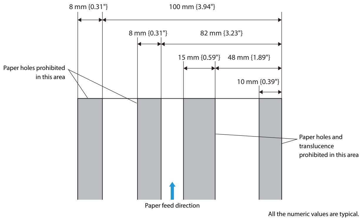
Printable Area
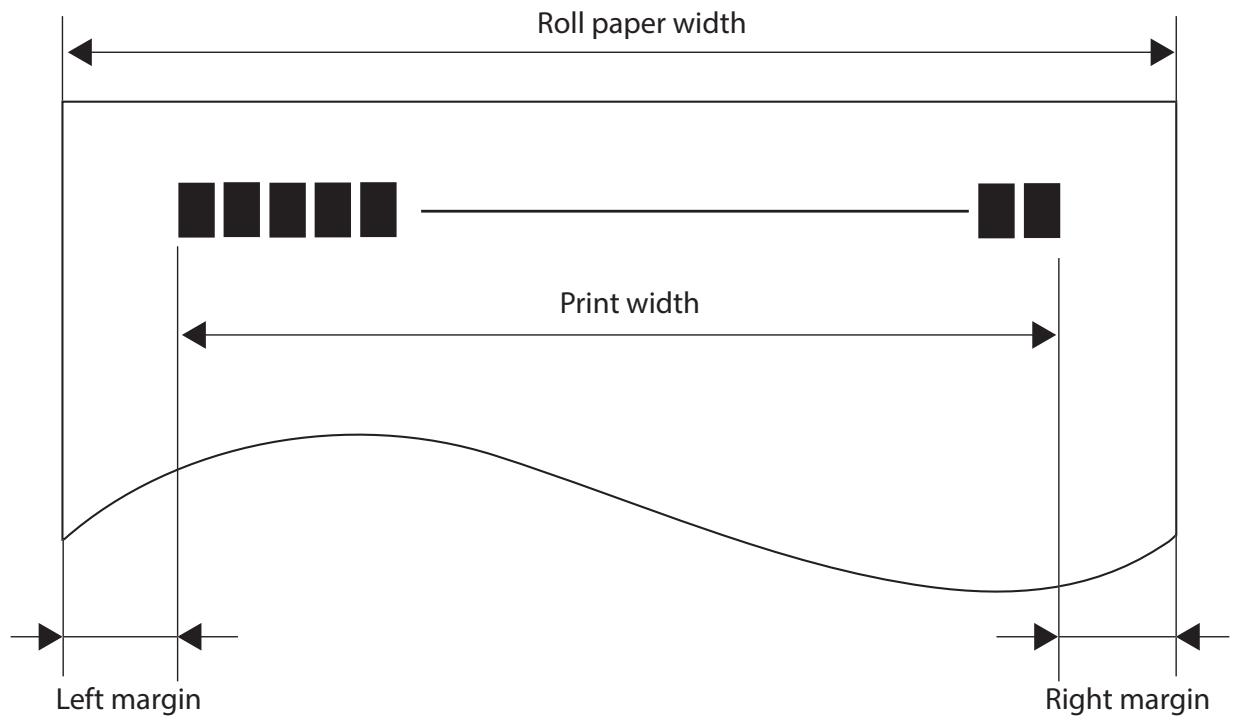
Roll paper
| Roll paper width | Print width | Left margin | Right margin |
| 57.5{2.26"} | 50.8{2.00"}(1200 dots) | 3.4{0.134"} | 3.3{0.130"} |
| 69.5{2.74"} | 61.0{2.40"}(1440 dots) | 4.2{0.165"} | 4.3{0.169"} |
| 76{2.99"} | 67.7{2.67"}(1600 dots) | 4.3{0.169"} | 4.2{0.165"} |
| 82.5{3.25"} | 72.2{2.84"}(1706 dots) | 6.0{0.236"} | 4.3{0.169"} |
[units: mm (All the numeric values are typical.)]
Slip paper for TM-J7200
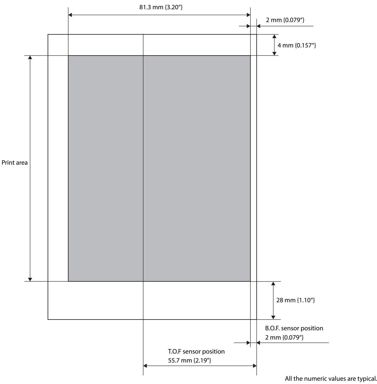
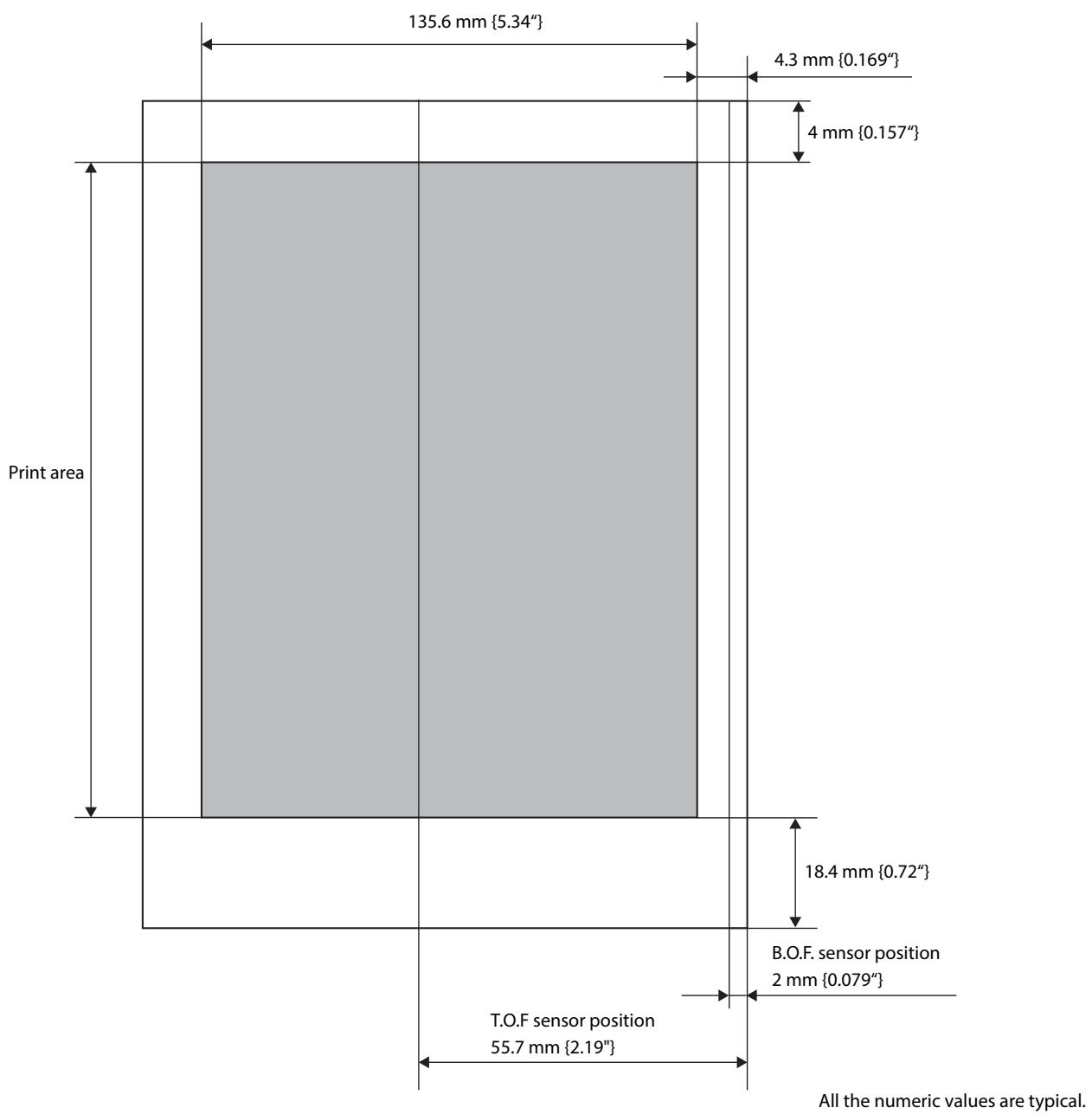
Slip paper for TM-J7700
Printing and Cutting Positions
Autocutting operation is enabled with roll paper only.
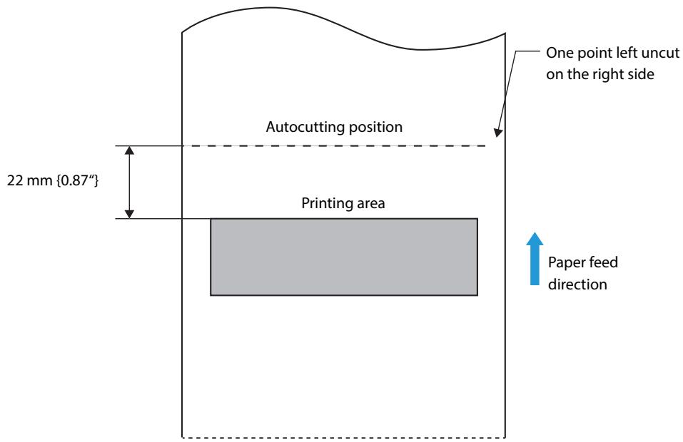
CAUTION
- The values above may vary slightly as a result of paper slack or variations in the paper. Take this into account when setting the cutting position of the autocutter.
Electrical Characteristics
| Operating voltage | DC 24V ± 7 % |
| Current consumption (24V, 25°C, standard print density) | Average: Approx. 1.8 A |
Environmental Conditions
| Temperature/Humidity | Operating | 10 to 35°C {50 to 95°F} 20 to 80% RH (No condensation |
| Storage | Ink cartridge installed: -20 to 40°C (-4 to 104°F) 20 to 85% RH (No condensation) Ink cartridge not installed: -20 to 60°C (-4 to 140°F) 5 to 85% RH (No condensation) (At -20°C (-4°F) or 60°C (140°F): up to 120 hours) | |
| Maximum absolute rated temperature | Humidity (%) 80 55 20 10 27 35 Temperature (°C) | |
| 70°C {158°F} (Including the operating and storage status.) | ||
| Air pressure (Altitude) | 700–1050 hPa (Approx. -20–2000 m (-21.87–2187.23 yards) above sea level) | |
| Acoustic noise (operating) | Approximately 55 dB (bystander position) Note: The values above are measured in the Epson evaluation condition. Acoustic noise differs depending on the paper used, printing contents, and the setting values, such as print speed or print density. | |
External Dimensions
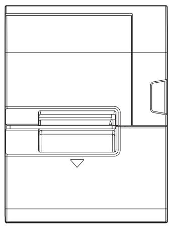
TM-J7200
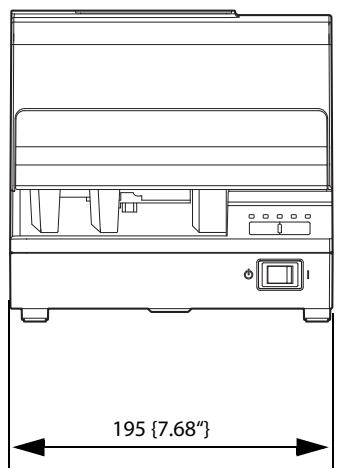
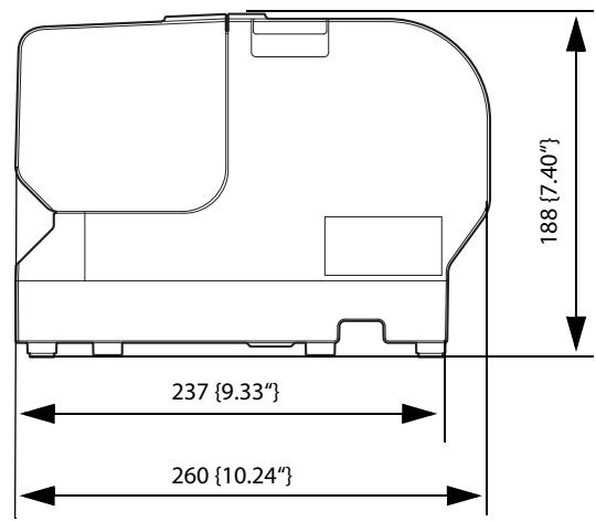
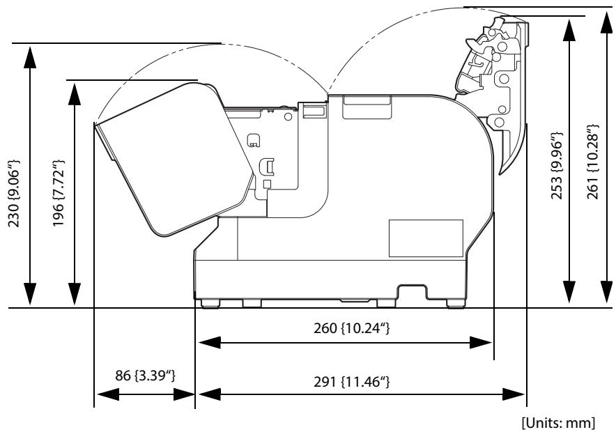
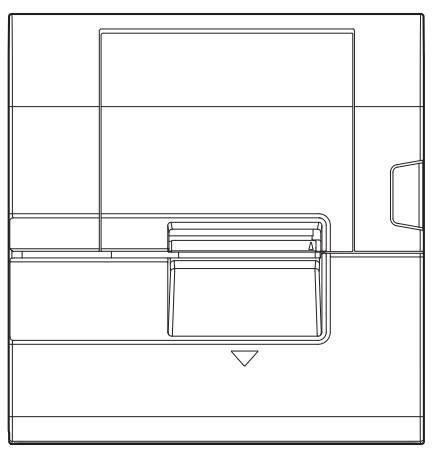
TM-J7700
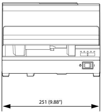
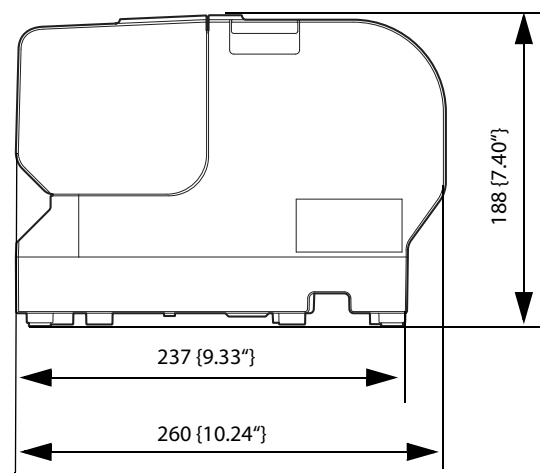
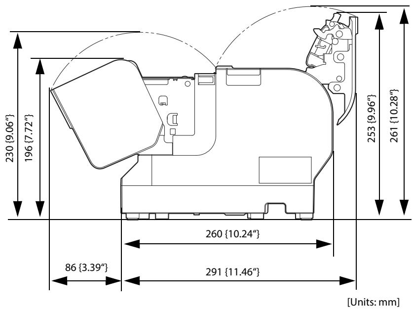
Ink cartridge
| Model number | SJIC33P(K) | |
| Ink colors | Black | |
| Ink type | Pigmented ink | |
| Expiration date | Expiration date 6 months after installation in the printer, 2 years after manufacture including the period of use | |
| Storage temperature | Transportation | -20 to 60°C (-4 to 140°F) (within 5 days when 60°C {140°F}) |
| Storage in individual packaging | -20 to 40°C (-4 to 104°F) (within 1 month when 40°C {104°F}) | |
| Installed | -20 to 40°C (-4 to 104°F) (within 1 month when 40°C {104°F}) | |
Character Code Tables
Refer to the following URL regarding the character code table.
http://www.epson-biz.com pos/reference/charcode/