USER MANUAL TFH 6630 X CATA
flowchart
graph TD
    A[" "] --> B[" "]
    B --> C[" "]
    C --> D[" "]
    D --> E[" "]
    E --> F[" "]
    F --> G[" "]
    G --> H[" "]
    H --> I[" "]
    I --> J[" "]
    J --> K[" "]
    K --> L[" "]
    L --> M[" "]
    M --> N[" "]
    N --> O[" "]
    O --> P[" "]
    P --> Q[" "]
    Q --> R[" "]
    R --> S[" "]
    S --> T[" "]
    T --> U[" "]
    U --> V[" "]
    V --> W[" "]
    W --> X[" "]
    X --> Y[" "]
    Y --> Z[" "]
cata
new tech
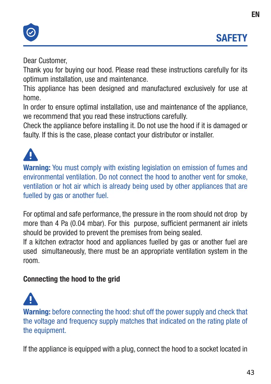
natural_image
Line drawing of a technical enclosure or enclosure with a grid-patterned metal grate (no text or symbols)
EN Installation, use and maintenance instructions

flowchart
graph TD
    A["●"] --> B["●"]
    B --> C["●"]
    C --> D["●"]
    D --> E["●"]
    E --> F["●"]
    F --> G["●"]
    G --> H["●"]
    H --> I["●"]
    I --> J["●"]
    J --> K["●"]
    K --> L["●"]
    L --> M["●"]
    M --> N["●"]
    N --> O["●"]
    O --> P["●"]
    P --> Q["●"]
    Q --> R["●"]
    R --> S["●"]
    S --> T["●"]
    T --> U["●"]
    U --> V["●"]
    V --> W["●"]
    W --> X["●"]
    X --> Y["●"]
    Y --> Z["●"]
    Z --> A["●"]
Tisztelt ügyfelünk!
natural_image
Two blue silhouette figures standing side by side with a checkmark symbol (no text or labels)


natural_image
Illustration of various office tools including screwdriver, flathead, and drill bit (no text or symbols)
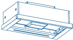
natural_image
Technical line drawing of a mechanical housing or enclosure with mounting brackets and internal compartments (no text or symbols)
01 x 1
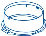
natural_image
Line drawing of a cylindrical mechanical component with mounting base (no text or symbols)
02 x1
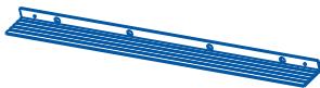
natural_image
Blue wireframe plate with evenly spaced holes, no text or symbols present
03x1
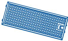
natural_image
Simple line drawing of a rectangular electronic component with grid pattern (no text or symbols)
04x1

natural_image
Blue rectangular grid pattern with a small U-shaped cutout at the bottom right corner (no text or symbols)
05x1

06 x 4
07 x 4
(6 x 40mm)


08 x 2
(4x 8mm)


09 x 2
(3x 12mm)
Nincs mellékelve
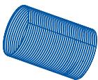
x 1
(∅125mm)

x 2

natural_image
Simple 3D geometric shape resembling a parallelogram with no text or symbols
| KIVEZETÉSES ÜZEMMÓD | BELSŐ KERINGTETÉSES ÜZEMMÓD |
 |  |
KIVEZETÉSES ÜZEMMÓD
natural_image
Line drawing of a 3D box with a hand pointing at a tray, labeled 'A' (no text or symbols on the diagram itself)
text_image
556
458
301
43
251
221.5
181.5
141.5
300
460
20
598
05
natural_image
Line drawing of a simple indoor space setup with a wall-mounted fixture and a diagonal saw (no text or symbols)
06
text_image
x4
Ø8mm
07

07 x 4

06 x 4
text_image
07
06
natural_image
Line drawing of a kitchen air vent with ventilation grilles (no text or symbols)
08
natural_image
Line drawing of a technical enclosure with ventilation grilles and a circular vent (no text or symbols)
09
x 1
(∅125mm)
natural_image
Technical line drawing of a mechanical assembly with three views of a cylindrical component (no text or symbols present)
10
natural_image
Line drawing of a cabinet with two doors and a mesh drain (no text or symbols)
natural_image
Diagram of a server rack with an arrow indicating direction, showing internal components and a magnified inset (no text or symbols)
Thank you for buying our hood. Please read these instructions carefully for its optimum installation, use and maintenance.
This appliance has been designed and manufactured exclusively for use at home.
In order to ensure optimal installation, use and maintenance of the appliance, we recommend that you read these instructions carefully.
Check the appliance before installing it. Do not use the hood if it is damaged or faulty. If this is the case, please contact your distributor or installer.

Warning: You must comply with existing legislation on emission of fumes and environmental ventilation. Do not connect the hood to another vent for smoke, ventilation or hot air which is already being used by other appliances that are fuelled by gas or another fuel.
For optimal and safe performance, the pressure in the room should not drop by more than 4 Pa (0.04 mbar). For this purpose, sufficient permanent air inlets should be provided to prevent the premises from being sealed.
If a kitchen extractor hood and appliances fuelled by gas or another fuel are used simultaneously, there must be an appropriate ventilation system in the room.
Connecting the hood to the grid

Warning: before connecting the hood: shut off the power supply and check that the voltage and frequency supply matches that indicated on the rating plate of the equipment.
If the appliance is equipped with a plug, connect the hood to a socket located in
EN
an accessible area which is compliant with existing standards.
If the appliance is not equipped with a plug, connect the appliance directly to the power grid, protected by an omnipolar separating device which can be accessed to disconnect it, in accordance with local regulations.
If the power cable is damaged, it must be replaced by the manufacturer through its post-sale service, or by similar, qualified personnel in order to prevent danger.
Using the hood

Warning: during electrostatic discharge (e.g. a flash of lightning) the hood may stop working. This does not involve risk of damage. Shut off the power supply to the hood and re-connect it after one minute.
Children under the age of 8 years should be kept away from the appliance unless under permanent supervision.
This appliance can be used by children of 8 years and over and people with reduced physical, sensory or mental capacities or a lack of experience or knowledge, if supervised by a person responsible for their safety or if they have been given suitable instructions regarding the safe use of the appliance and they understand the risks involved. Children should not play with the appliance. The cleaning and maintenance to be performed by the user should not be carried out by unsupervised children.
To avoid the risk of fire, the metal filter should be cleaned regularly.
Containers with hot oil should be monitored continuously.
Do not set food alight under the hood.
Accessible parts may become hot when used with cooking appliances.
The manufacturer:
- Declares that this appliance complies with the essential requirements for low-voltage electrical equipment, as set out in Directive 2014/35/EU, and electromagnetic compatibility, as set out in Directive 2014/30/EU.
- Shall not be held responsible for failure to follow the instructions given in this manual or non-compliance with safety standards relating to the correct use of
the equipment.
- Shall not be held responsible for any damage caused by the incorrect installation, use or maintenance of the appliance.
- Reserves the right to make any changes to the equipment or this manual without giving prior notice.
Should you need technical assistance or additional information about our products, please contact your distributor or an official, authorised technical service.

ELECTRIC INSTALLATION
Make sure the maximum air extraction flow rate for the appliances in the room does not exceed 4 Pa (0.04 mbar). The room must have adequate ventilation if an extractor hood is used simultaneously with appliances that run on gas or other fuels. The evacuated air must be extracted through ducts that are used for evacuating fumes from appliances that run on gas or other fuels. Regulations regarding air extraction must be complied with.
This product in intended for HOUSEHOLD USE only.
Use a rigid PVC pipe with a min. ∅ l20 mm to evacuate fumes outside.
The above restrictions do not apply to hoods with no fumes outlet to outside (recirculation system with activated charcoal filter).

Warning: Failure to install the screws or fixing device in accordance with these instructions may result in electrical hazards.
Installation and connection
- This appliance is only intended for domestic use.
- Please observe the special installation instructions.
- The appliance is fitted with a plug and must only be connected to a properly installed earthed socket.
- The mains voltage must correspond to the voltage specified on the rating plate.
- The socket must be installed and connecting cable must only be replaced by a qualified electrician. If the plug is no longer to accessible following installation, an all-pole disconnecting device must be present on the installation side with a contact gap of at lease 3mm.
-Adapters, multi-way strips and extension leads must not be used. Overloading can result in a risk of fire.

Warning: This is a Class I appliance and MUST be earthed.
This appliance is supplied with a 3 core mains cable coloured as follows:
- Brown = L or Live
- Blue = N or Neutral
- Green and Yellow = E or Earth

text_image
EUR
N BLUE
L BROWN
GREEN/YELLOW
UK
DOUBLE POLE SWITCHED
FUSED SPUR OUTLET
USE A 3AMP FUSE
x2

natural_image
Two stylized human figures with a checkmark, no text or symbols present


natural_image
Illustration of various hand tools including a screwdriver, screwdriver, and drill bit (no text or labels)
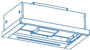
natural_image
Technical line drawing of a mechanical housing or enclosure with mounting brackets and internal compartments (no text or symbols)
01 x 1
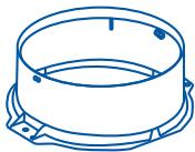
natural_image
Line drawing of a cylindrical mechanical component with mounting base (no text or symbols)
02 x1

natural_image
Blue wireframe plate with evenly spaced holes, no text or symbols present
03x1
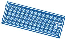
natural_image
Simple line drawing of a rectangular electronic component with grid pattern (no text or symbols)
04x1
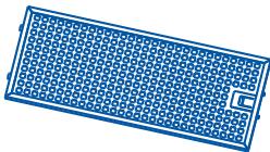
natural_image
Blue rectangular grid pattern with a small U-shaped cutout at the bottom right corner (no text or symbols)
05x1

06 x 4
07 x 4
(6 x 40mm)


08 x 2
(4x 8mm)


09 x 2
(3x 12mm)
Not included
x 1
(∅125mm)

x 2

natural_image
Simple 3D geometric shape resembling a parallelogram with no text or symbols
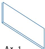
A x 1
Choose a type of installation:
| SUCTION VERSION(extraction to the outside) | FILTERING VERSION(no extraction to the outside) |
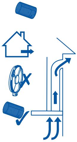 | 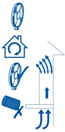 |
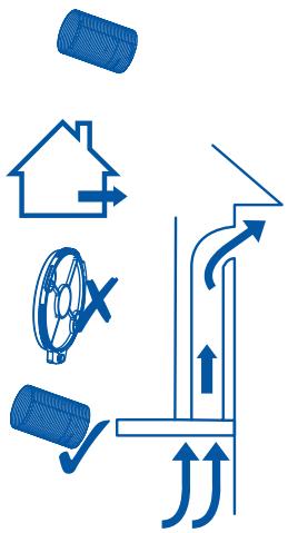
SUCTION VERSION
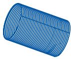
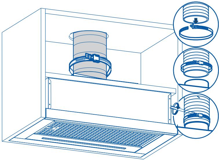
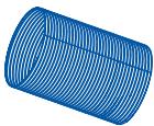
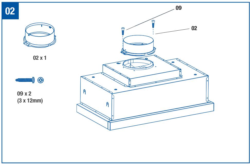
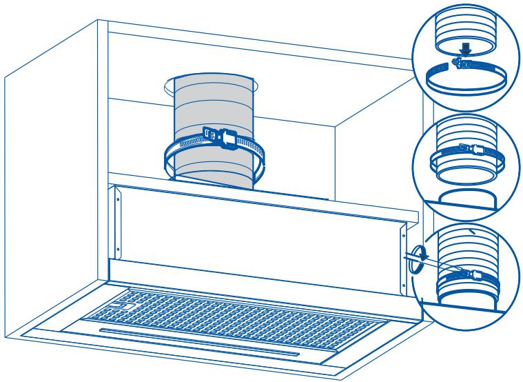
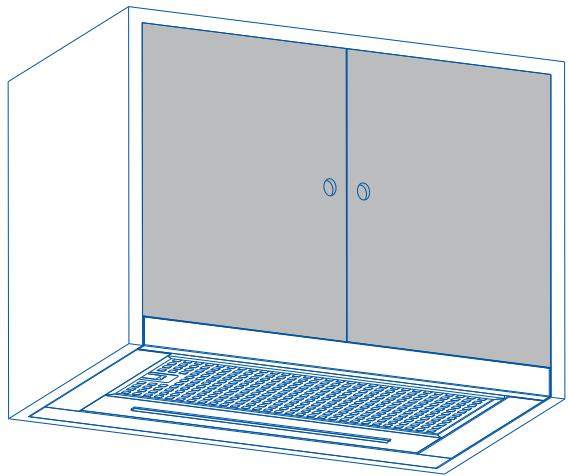
If the hood is to be installed as a SUCTION hood, connect the plastic outlet piece supplied with the hood (120mm diameter pipe for better performance and lower noise levels.
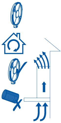
FILTERING VERSION (INTERNAL RE-CYCLING)
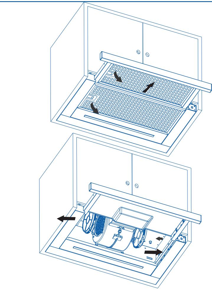
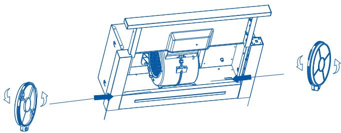
When there is no exhaust duct for venting out-door, you can use a carbon filter. The air is depu-rate by the filter and put again in the surrounding.
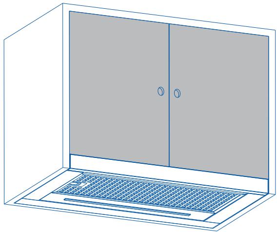
The air is released in the room through a connecting pipe, which goes through the hanging cupboard and us connected to the connecting ring supplied.
To use the appliance in this version, proceed as follows:
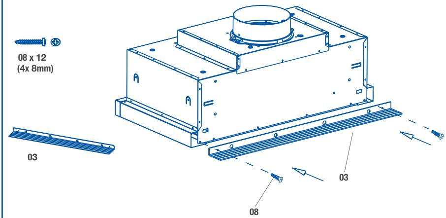
- Open the grids
- To proceed to change the charcoal filter, the screw has to be removed.
- Reinstall the grids.
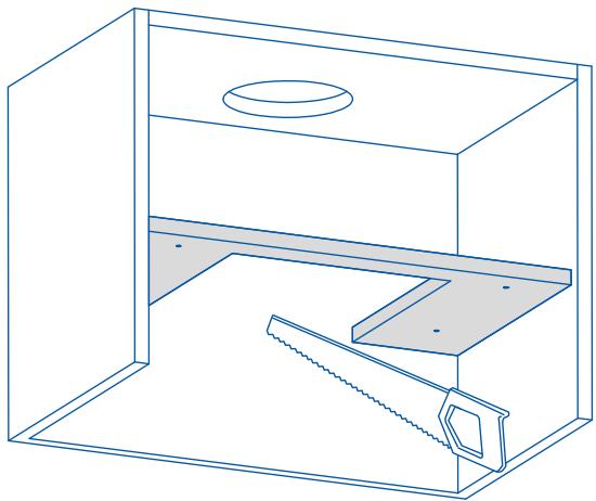
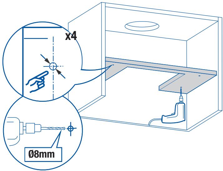
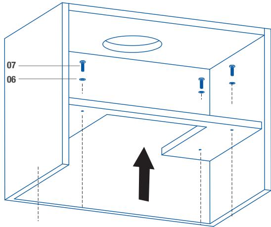
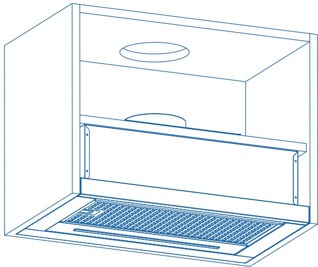
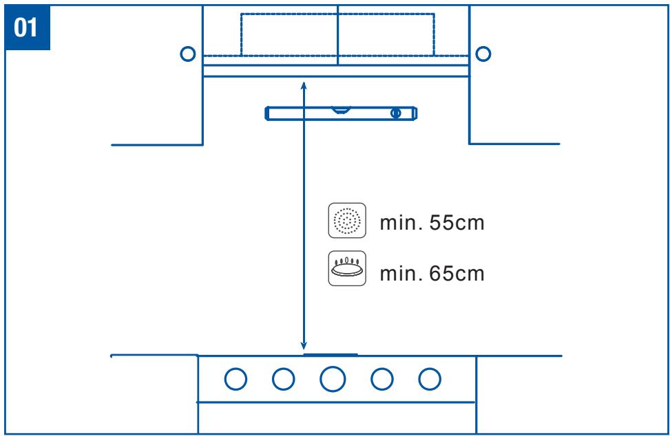
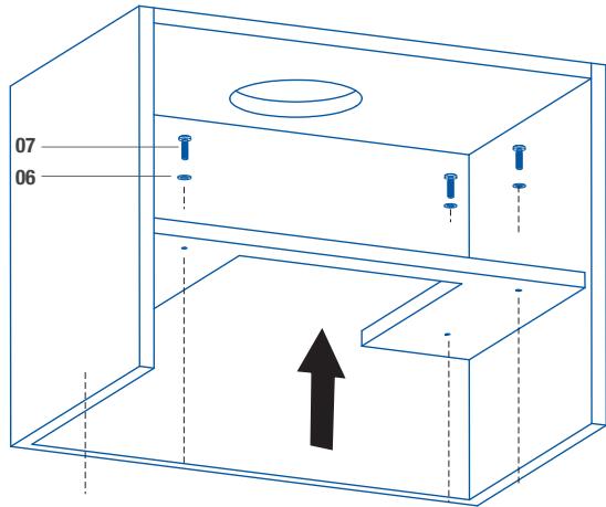
Install the hood in line with the instructions on the template.
For gas cooking appliances only: the minimum distance to the Hood must be at least 65 cm.
text_image
01
min. 55cm
min. 65cm
text_image
02
02 x 1
09 x 2
(3 x 12mm)
09
02
03
text_image
08 x 12
(4x 8mm)
03
03
08
04

A x1
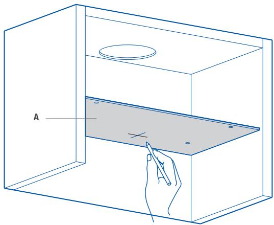
natural_image
Line drawing of a 3D box with a hand pointing to a tray, labeled 'A' (no text or symbols on the diagram itself)
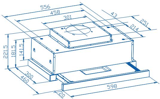
text_image
556
458
301
43
251
221.5
181.5
141.5
300
460
20
598
05
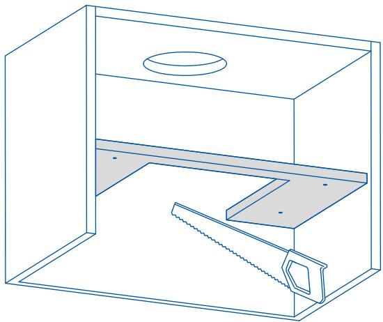
natural_image
Line drawing of a simple room setup with a sink, shelf, and saw (no text or symbols)
06
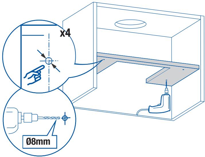
text_image
x4
Ø8mm
07

07 x 4

06 x 4
text_image
07
06
natural_image
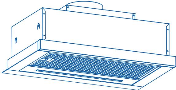
Line drawing of a kitchen air vent with ventilation grilles (no text or symbols)
08
natural_image
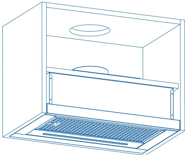
Line drawing of a technical enclosure with ventilation grilles and a circular vent (no text or symbols)
SUCTION VERSION
09
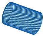
x1
(∅125mm)
natural_image
Technical line drawing of a mechanical assembly with three views of a cylindrical component inside a housing (no text or symbols)
10
natural_image
Line drawing of a cabinet with two doors and a mesh drain (no text or symbols)
11

x 2
natural_image
Technical line drawing of a laptop with internal components and airflow indicators (no text or symbols)
natural_image
Technical line drawing of a mechanical device with two wheels and a central motor (no text or symbols)
To obtain the best results from your cooker hood it is recommended that you leave it switched on for up to 15 minutes after you have finished cooking.
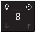 |
| SDM0 | Light On/Off |
| SDM1 | Fan On/Off and Speed Reduction |
| SDM2 | LED Display |
| SDM3 | Boost Function and Speed Increase |
| SDM4 | Timer |
To Set Up For First Use
Ducted Option
This is the factory default setting if you are extracting air to the outside.
Recirculation Option
This is the option to be used with carbon filters.
To change to this option, press both Speed icons ↓ ↑ together and the Timer ⏻ will flash red.
Press the Speed Increase ↑ to change to the Recirculation Option ☐ and the Speed Reduction ↓ to revert back to the Ducted Option ☐. Finally, press both Speed icons ↓ ↑ together one more time to confirm the change and the Timer ⏱ will stop flashing.

NOTE: This operation must be undertaken within two minutes of switching the power on at the mains outlet. To change this setting at a later time, switch off the power at the mains outlet, wait a few seconds, turn on the power and repeat the above.
02 General Use
Light On/Off
- Use this control to switch the light on independently of the fan motor, it will be lit red in this mode.
- When the fan is in use, and the light is off, the icon will be lit white in this mode, but will turn red if the light is then switched on.
Fan On/Off and Speed Reduction
- Press this icon once to turn on the fan motor at speed 1. All icons will be lit white and the light icon will be red if already in use.
- If the motor is on speed 1, pressing and holding this icon for two seconds will turn off the fan motor. As above, the light control is independent of this operation.
- If the motor is higher than speed 1, this will reduce the fan speed with each press of the icon.
LED Display
- Shows the extraction mode during set up ☐ or ☑ and the motor speeds from 1-5, and P for Boost. Boost Function and Speed Increase
- Press this icon once to turn on the fan motor at full power, and P will flashinthedisplay,
- If the motor is already on speed 1-5, each press of this icon will increase the fan speed accordingly.
- If you press and hold the icon for two seconds, the fan speed will increase to full power and P will flashinthedisplay.

NOTE: Full power or Boost only operates for five minutes maximum to conserve energy and the fan speed will automatically drop to speed level 5 after this time.
Timer
- When the fan motor is on and the Timer 🔒 icon is pressed, the icon will be lit red and the current speed in the display will start to flash.
- The chosen speed level will remain in use for five minutes before dropping downtothenext lowest speed. This speed will remain in operation for two minutes before dropping down again. This will be repeated every two minutes unless the speed is already at level 1 and then the fan will turn off. If the light is already on, this will also be turned off.
- Pressing the Speed Reduction↓ or Speed Increase ↑ icon during a current timer program will restart the countdown process again with a fiveminutecycle.
- If the Timer 📋 icon is pressed again during a current timer program, the cycle will be cancelled, the icon will revert to white and the current fan speed will remain on indefinitely.
- The maximum timer program cycle is 15 minutes: 5 minutes on P and then 2 minutes each on speed 5 down to speed 1.
CONECTE LAS LÁMPARAS
natural_image
Diagram of a server rack with an arrow indicating direction, showing internal components and a magnified inset (no text or symbols)

Warning: always switch off the electricity supply before carrying out maintenance work on the hood. In the event of a fault, contact an official distributor or authorised dealer.
Cleaning the outside: use liquid, non-corrosive detergent and avoid using abrasive cleaning products and solvents. Do not use high-pressure or steam cleaning devices.

Important: increase the filter cleaning/replacement frequency if the hood is used for more than 2 hours a day. Always use genuine filters from the manufacturer.
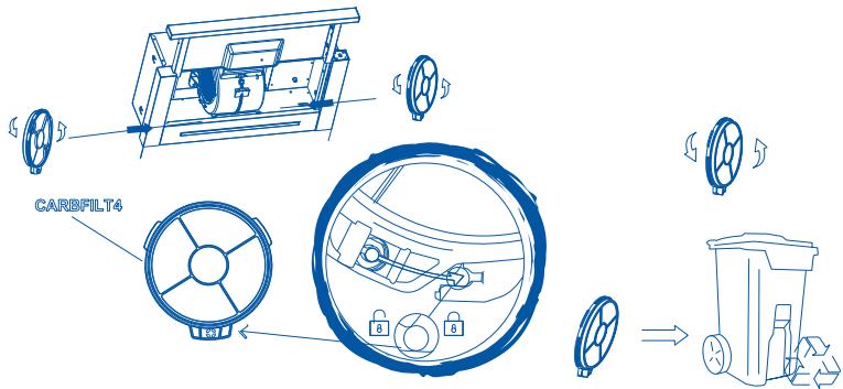
Carbon filter replacement
Activated charcoal filters: replace them every 3 months.
3 MONTHS

text_image
CARBILT4
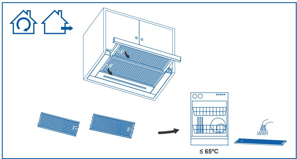
Grease cleaning
To avoid fires, clean thoroughly once a month or whenever the display pilot light indicates as such. To do so, remove the filters and wash with hot water and detergent. If using a dishwasher (metal parts may turn black without this affecting their functional capacity), load the filters vertically to avoid solid residue from being deposited.
1 month
text_image
≤ 65°C
Lamp replacement

Warning: do not handle the bulbs until the electricity supply has been switched off and they have cooled.

Important: use new bulbs according to that indicated on the hood nameplate.
If using LED lighting, do not look directly at the light.
Use bulbs with an aluminium reflector to replace halogen bulbs. Do not use dichroic bulbs - risk of overheating.
For LED lamp replacements, please contact Technical Support or the distributor of the brand.
cata
new tech
Importór:
MULTIKOMPLEX BUDAPEST KFT.