HYPNOSE INCLINEE 800 - Range hood ROBLIN - Free user manual and instructions
Find the device manual for free HYPNOSE INCLINEE 800 ROBLIN in PDF.

User questions about HYPNOSE INCLINEE 800 ROBLIN
0 question about this device. Answer the ones you know or ask your own.
Ask a new question about this device
Download the instructions for your Range hood in PDF format for free! Find your manual HYPNOSE INCLINEE 800 - ROBLIN and take your electronic device back in hand. On this page are published all the documents necessary for the use of your device. HYPNOSE INCLINEE 800 by ROBLIN.
USER MANUAL HYPNOSE INCLINEE 800 ROBLIN
MANUEL D'INSTALLATION
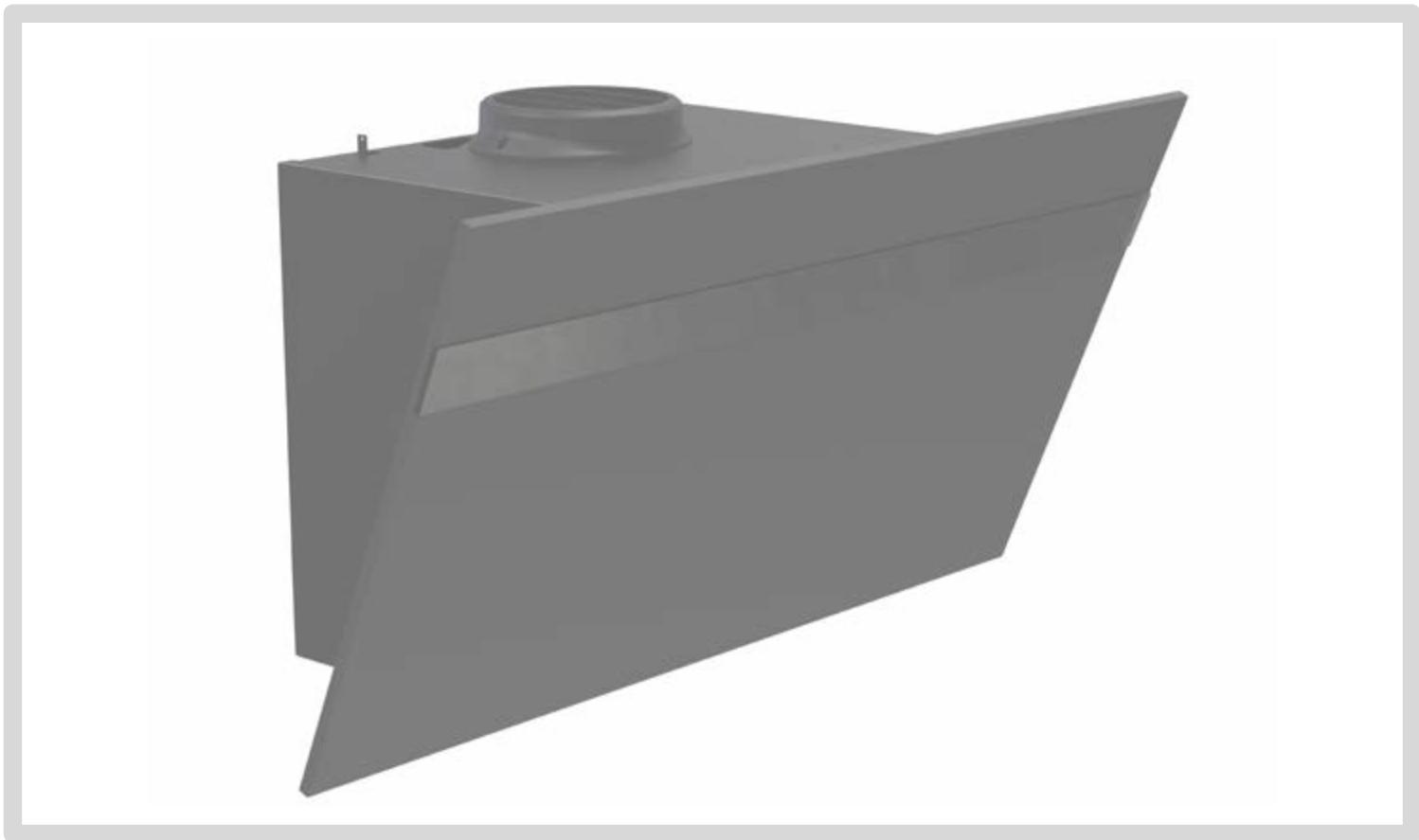
natural_image
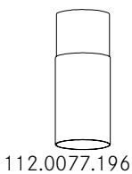
3D rendering of a gray industrial or mechanical component with a flanged base and central cylindrical feature (no text or symbols)HYPNOSE INCLINEE
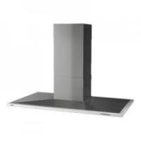
Kitchen extractor hood
Küchenabzugshaube
Cappa aspirante
Campana extractora
text_image
Three human figures with checkmark and cross symbols indicating approval or rejection status


A
1x

B
1x

C
1x
1x
E
1x

F
1x
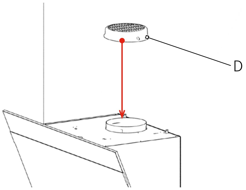
D
1x


G
1x
text_image
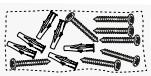
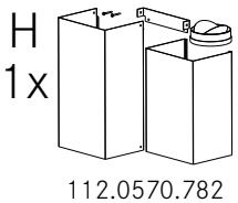
H 1x 112.0570.782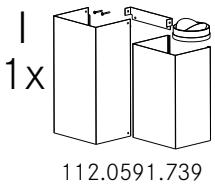
text_image
1x 112.0591.739
F
1x


K
1x
112.0540.798

text_image
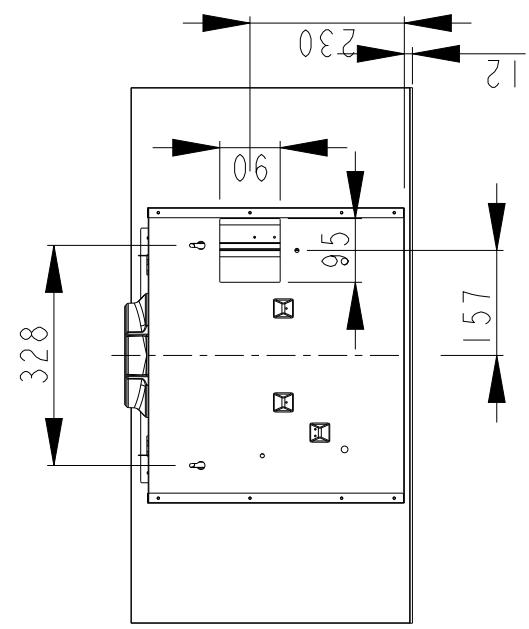
328 90 230 12 95 157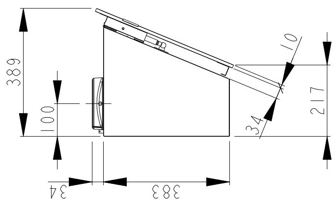
text_image
389 100 34 217 383 34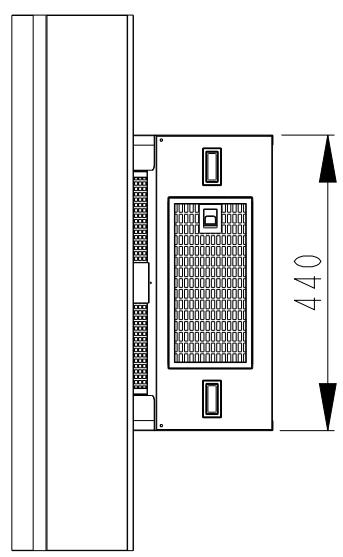
text_image
440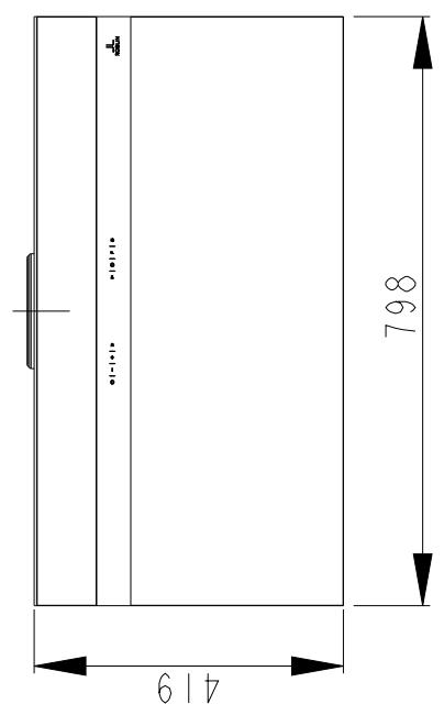
text_image
4 798 619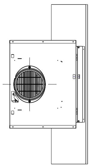
natural_image
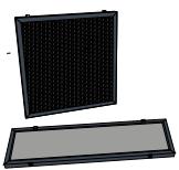
Technical line drawing of a mechanical component with internal grid pattern and mounting brackets (no text or symbols)
text_image
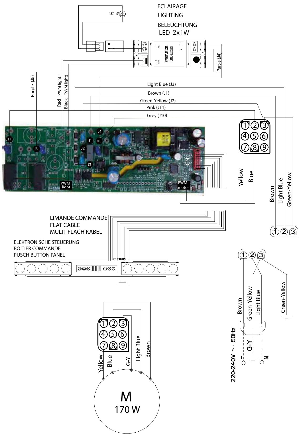
ECLAIRAGE LIGHTING BELEUCHTUNG LED 2x1W Purple (J4) Red (PWM light) Black (PWM light) Light Blue (J3) Brown (J1) Green-Yellow (J2) Pink (J11) Grey (J10) J11 J5 J4 J1 J10 CNT PWM light PWM motor Yellow Blue Brown Light Blue Green-Yellow LIMANDE COMMANDE FLAT CABLE MULTI-FLACH KABEL ELEKTRONISCHE STEUERUNG BOITIER COMMANDE PUSCH BUTTON PANEL CONN Yellow Blue G-Y Light Blue Brown M 170 W 220-240V ~ 50Hz L Brown Green-Yellow Light Blue Green-Yellow N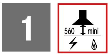
text_image
Diagram illustrating electric field (E) and magnetic field (B) vectors with positive and negative charges, showing electron movement in a circular region.
text_image
4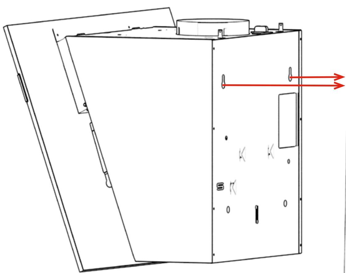
natural_image
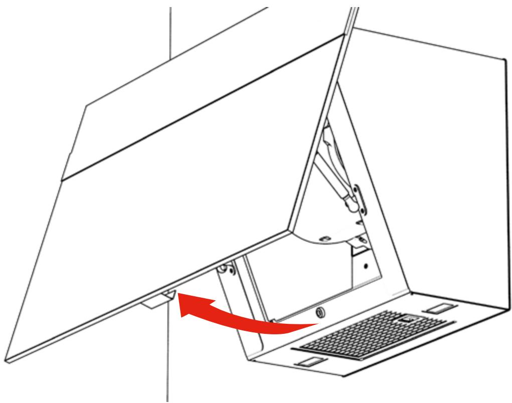
Technical line drawing of a device casing with internal components and red directional arrows indicating flow or movement (no text or symbols)5
natural_image
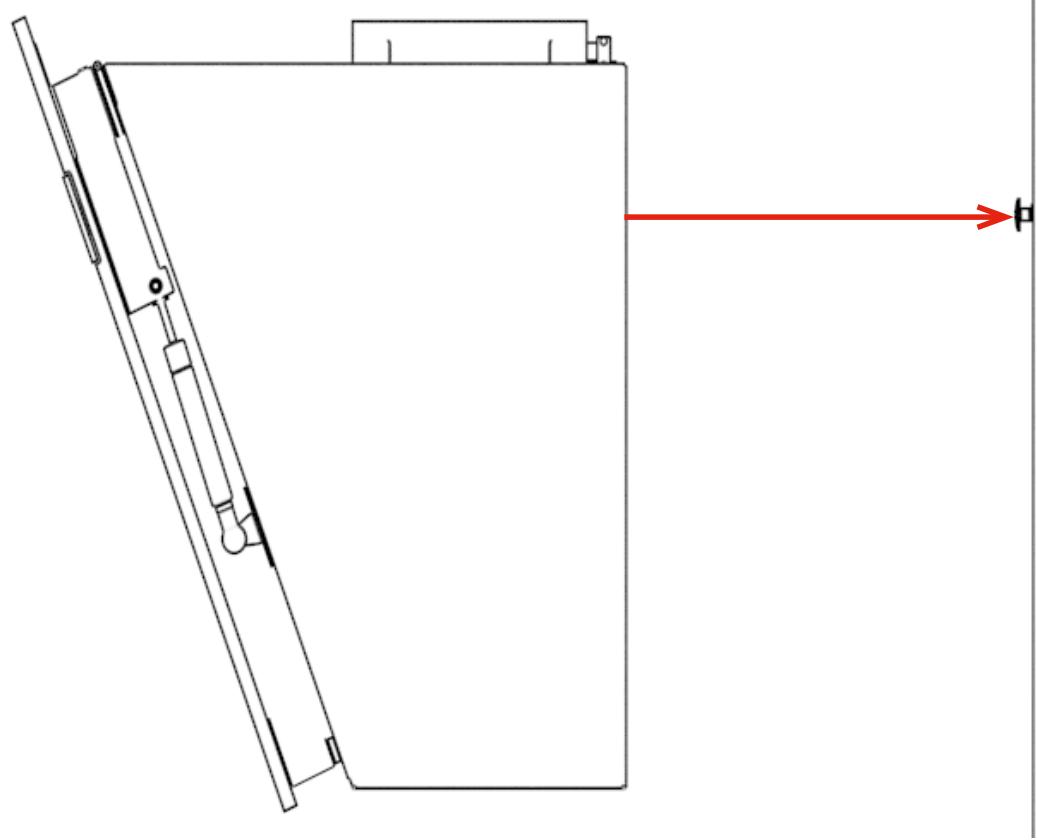
Technical line drawing of a mechanical assembly with a red arrow pointing to a component (no text or symbols present)6
natural_image
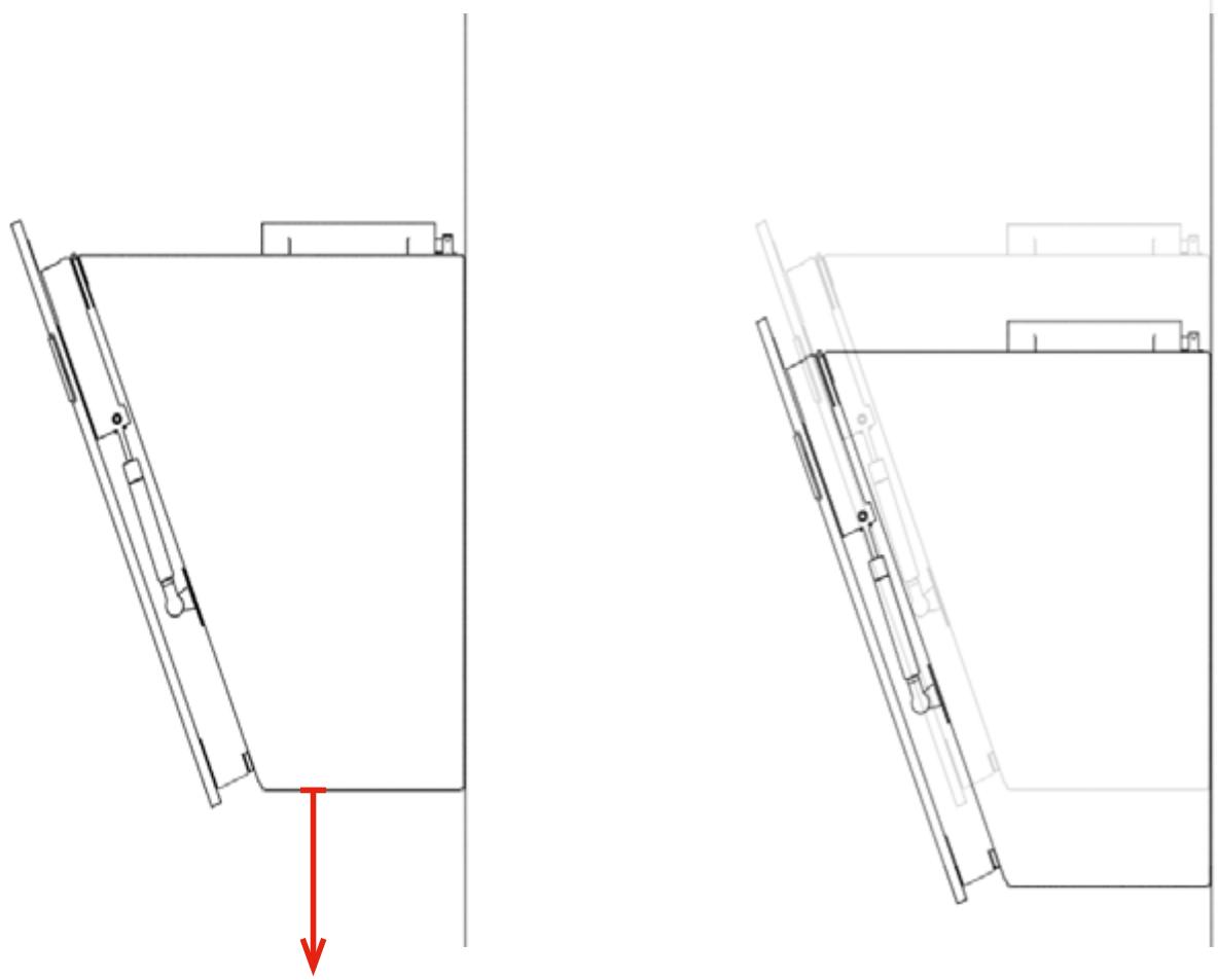
Technical line drawing of a mechanical component with two views, one showing a downward arrow and the other a bracket (no text or symbols)2
1
text_image
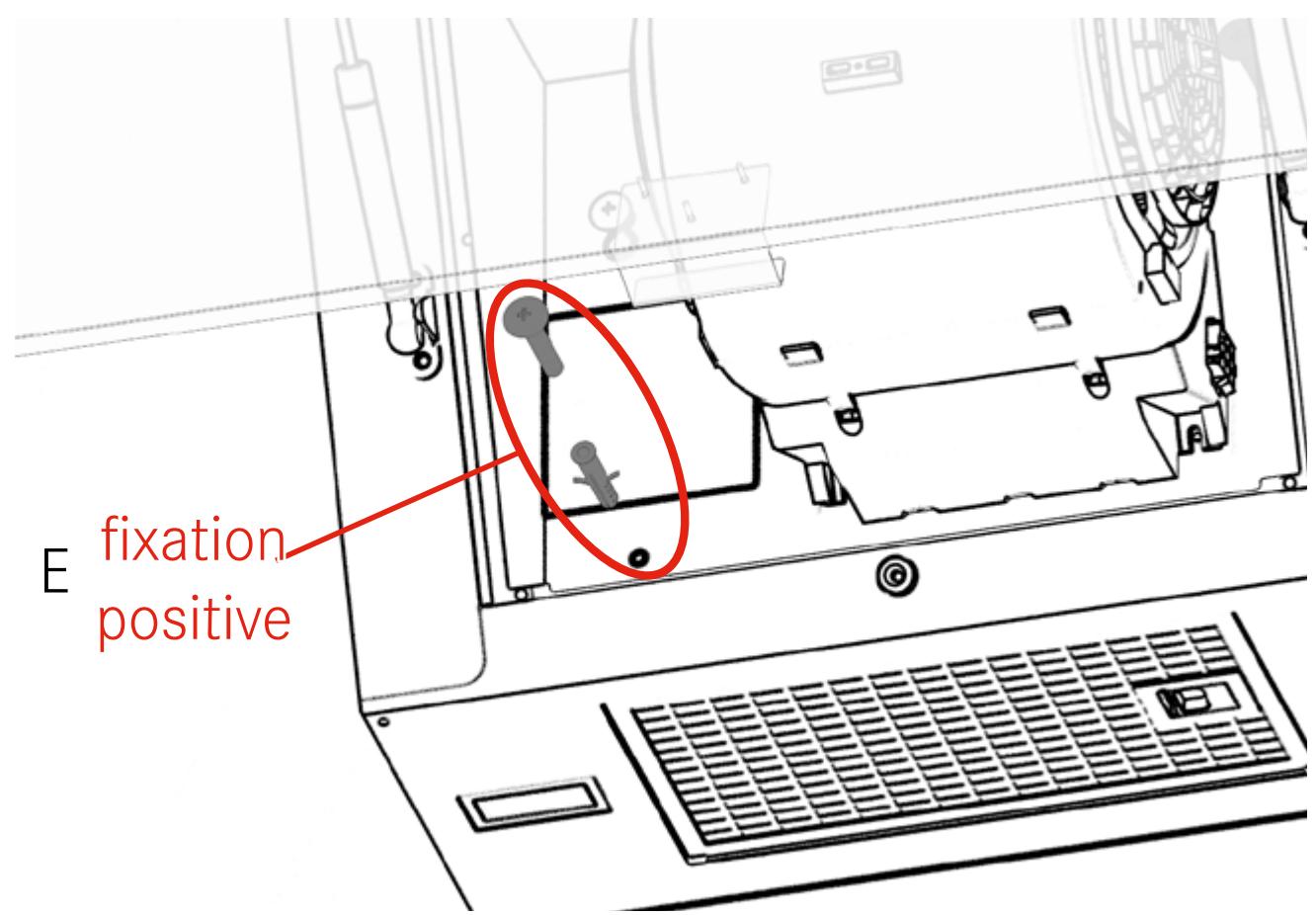
E fixation positive2
text_image
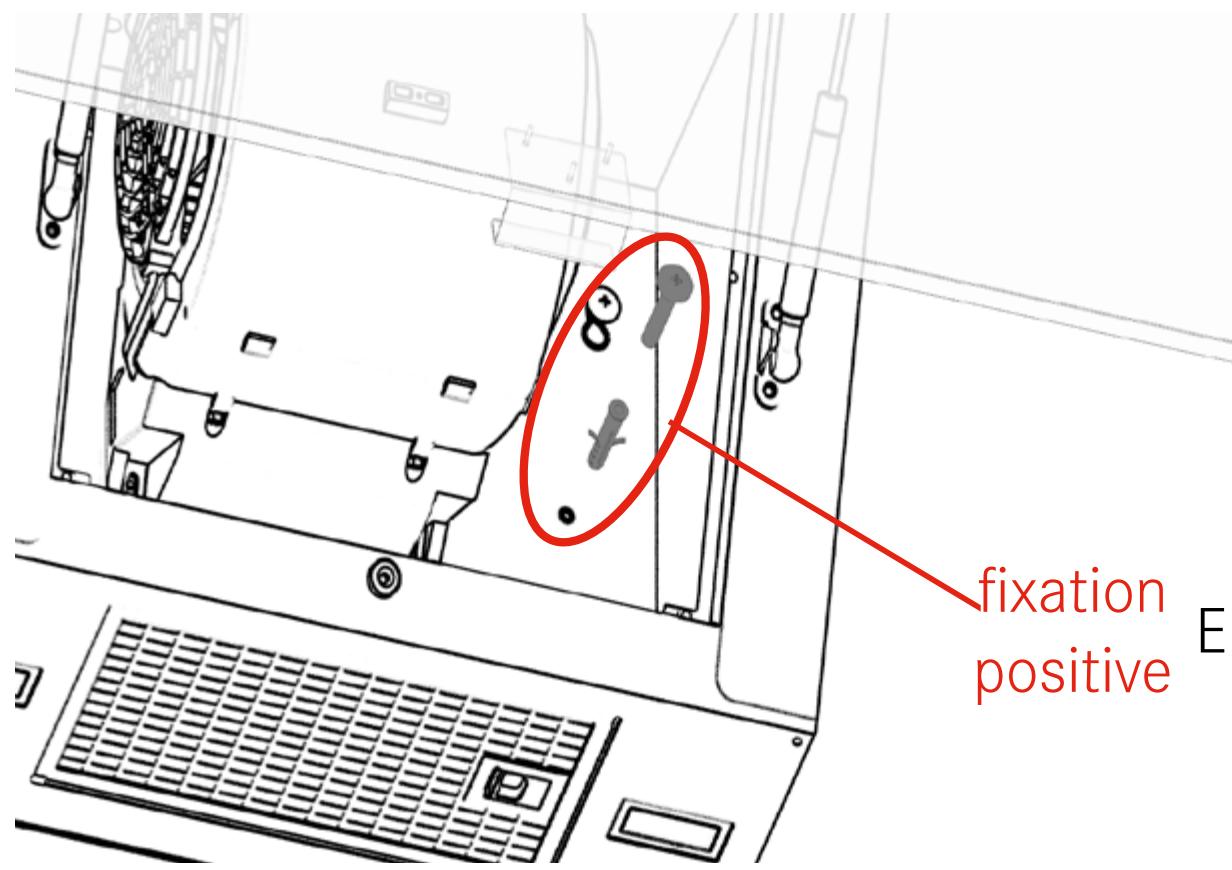
fixation positive3
1
text_image
D2

natural_image
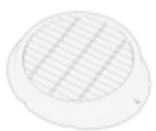
Line drawing of a cabinet or enclosure with a central circular component and a side panel (no text or symbols)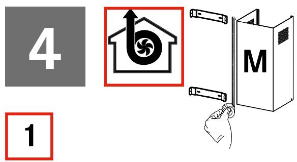
text_image
4 1 M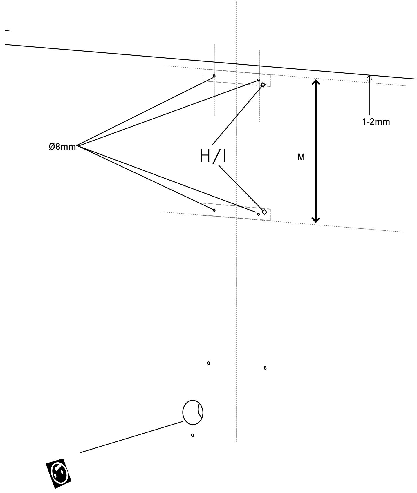
text_image
Ø8mm H/I M 1-2mm2
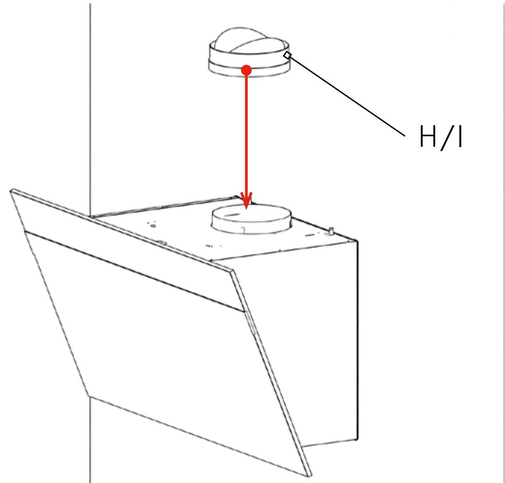
text_image
H/I3
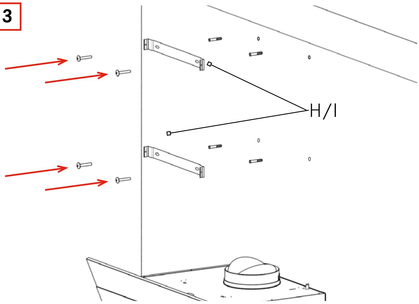
text_image
3 H/I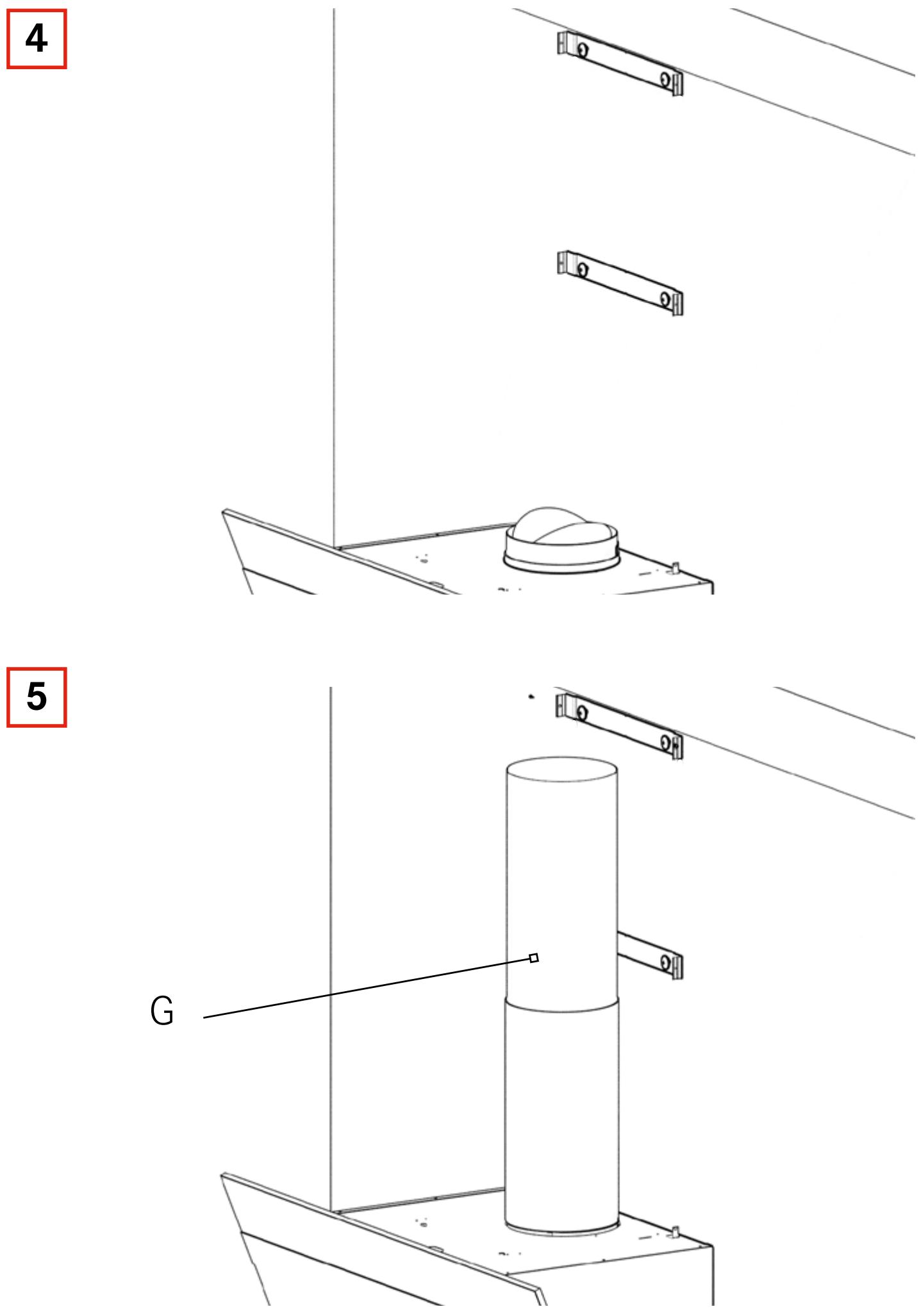
text_image
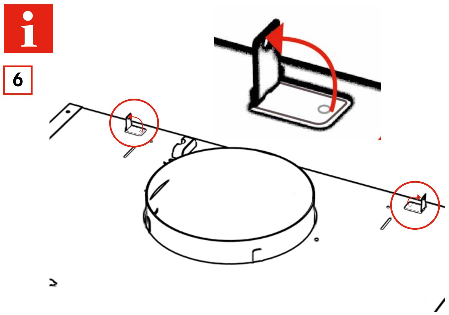
i 6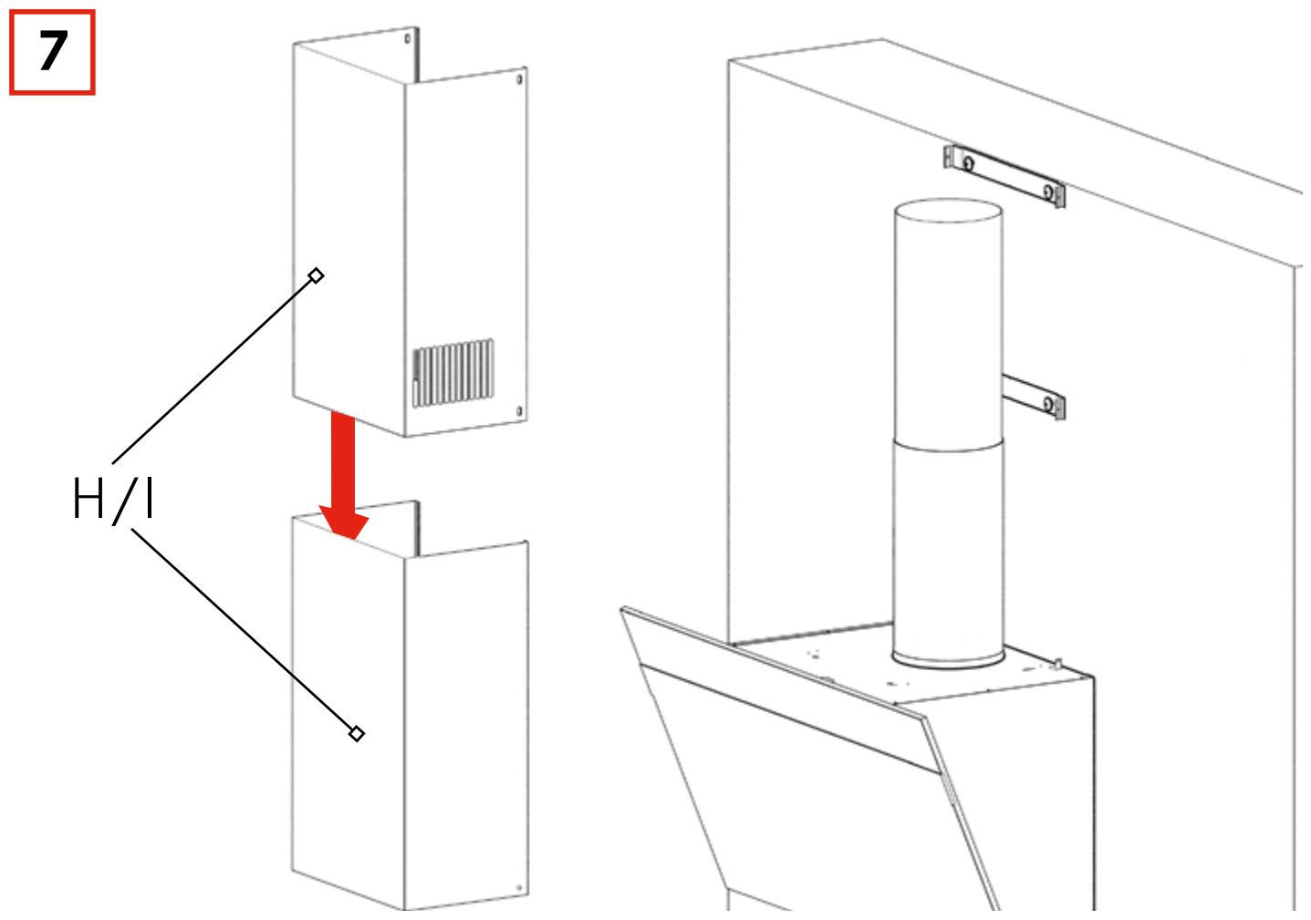
text_image
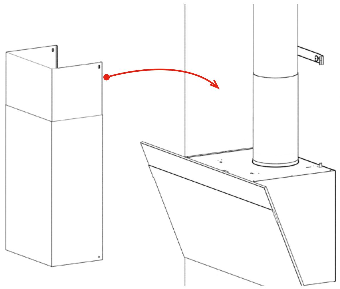
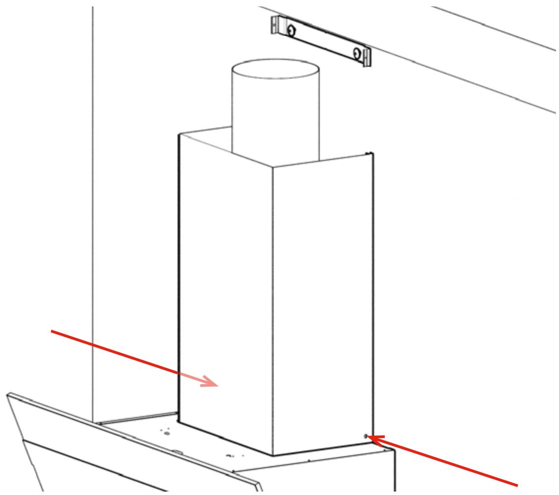
7 H/I8
natural_image
Technical line drawing of a mechanical assembly with a red arrow indicating motion or transformation (no text or symbols present)9
natural_image
Technical line drawing of a mechanical assembly with a cylindrical component and red directional arrows indicating motion (no text or symbols)10

natural_image
Technical line drawing of a mechanical assembly with a red upward arrow indicating motion or force (no text or symbols)11
natural_image
Technical line drawing of a mechanical assembly with a circular component and two red arrows indicating direction (no text or symbols)5
1
natural_image
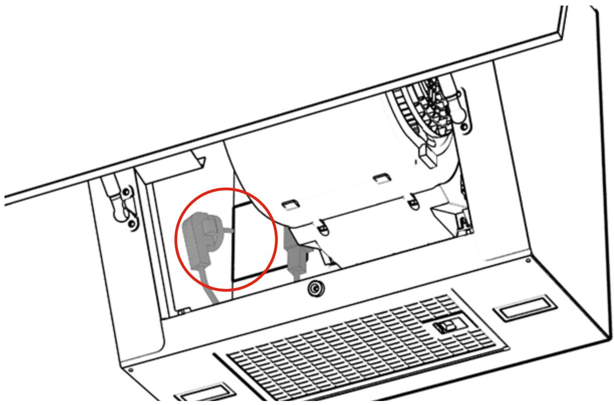
Diagram of a laptop interior showing the open base and internal components, with a red arrow indicating a specific location (no text or symbols present)2
natural_image
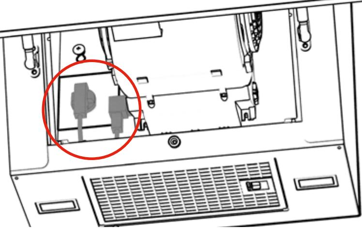
Laptop interior view showing internal components and a highlighted device (no text or symbols visible)3
natural_image
Diagram of an open laptop with a highlighted device component (no text or symbols present)
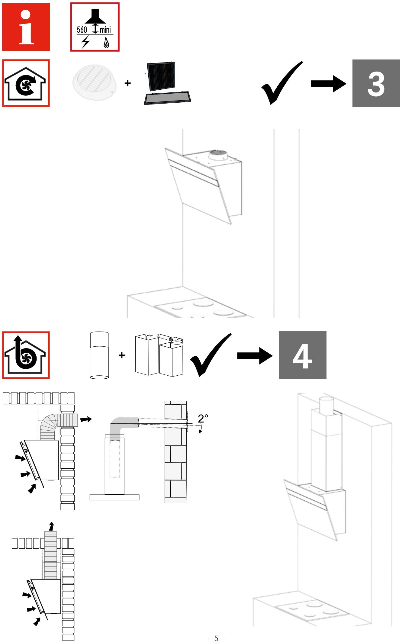
Installation
▶ Make sure that the installation is carried out only by specifically trained and qualified personnel.
▶ During installation observe the applicable regulations concerning exhaust air.
▶ Mount the device only with suitable fixing material.
▶ Make sure that damaged cables are changed by the manufacturer or the customer service.
Mounting location
▶ Make sure that the kitchen has an opening to the outside to ensure a sufficient air exchange.
If the hood is used along with devices that do not require electricity:
▶ Make sure that the negative pressure in the room does not exceed 0.04 mbar to ensure that the exhaust gases will not be drawn in again.
Spacing
▶ Observe the safety distance between stove top and hood.
If the installation instructions for a gas-powered stove top require a greater distance than specified in these installation instructions:
▶ Observe the specifications of the gas-powered stove top.
Connecting the smoke vent
▶ Do not connect the hood to a shaft that is used for flue gas (e.g. from a fireplace, heating system etc.).
▶ Connect the hood to the smoke vent with a pipe and make sure that the route of the pipe is as short as possible.
▶ If gas-powered devices or similar devices that do not require electricity are used in the same room as the hood: Ensure a sufficient ventilation to avoid the backflow of exhaust gases.
Electrical connection
▶ Observe the supply voltage (see type plate).
For devices of class I: Make sure that the power grid in the building is earthed correctly.
▶ Connect the hood to the mains power supply with a double-pole switch with a contact gap width of at least 3 mm.
Franke France S.A.S.
B.P 13 - Avenue Aristide Briand
60230 Chambly (France)