
TM-L90 - Thermal receipt printer EPSON - Free user manual and instructions
Find the device manual for free TM-L90 EPSON in PDF.


| Product Type | Thermal receipt printer |
| Brand | EPSON |
| Model | TM-L90 |
| Printing method | Online thermal printing |
| Resolution | 203 dpi × 203 dpi |
| Supported paper widths | 80 mm, 58 mm, 40 mm |
| Dimensions (W × D × H) | 140 × 203 × 148 mm |
| Weight | Approximately 1.9 kg |
| Power supply | 24 V DC power adapter, consumption approximately 1.8 A |
| Interfaces | Ethernet 110BASE-T/100BASE-TX, 2 USB host ports, 1 USB device port, micro SD card slot, cash drawer connector |
| Indicators and buttons | Power/off indicator, error indicator, paper indicator, paper feed button |
| Main functions | Receipt printing, self-test, reset, manual paper feed |
| Installation | Horizontal or vertical, interchangeable paper guide |
| Maintenance and cleaning | Clean the case with a dry or damp cloth; clean the inside (thermal head, roller, blade) with a cotton swab soaked in isopropyl alcohol |
| Safety | Disconnect if smoke or odor occurs; do not use in presence of flammable vapors; thermal head hot after printing; do not open cover during printing |
| Spare parts and repairability | Paper rolls, paper guide, power adapter; do not repair yourself, contact an authorized Epson center |
| General information | EPSON trademark; open source software included; usage restrictions for critical applications; manual available for download |
Frequently Asked Questions - TM-L90 EPSON
User questions about TM-L90 EPSON
0 question about this device. Answer the ones you know or ask your own.
Ask a new question about this device
Download the instructions for your Thermal receipt printer in PDF format for free! Find your manual TM-L90 - EPSON and take your electronic device back in hand. On this page are published all the documents necessary for the use of your device. TM-L90 by EPSON.
USER MANUAL TM-L90 EPSON
Standards and Approvals
The following standards are applied only to the products that are so labeled. (EMC is tested using the Epson power supplies.)
North America: FCC Class A, CAN ICES-3 (A)/NMB-3 (A)
WARNING
The connection of a non-shielded interface cable to this device will invalidate the EMC standards of this device. You are cautioned that changes or modifications not expressly approved by Seiko Epson Corporation could void your authority to operate the equipment.
FCC Compliance Statement for American Users
This equipment has been tested and found to comply with the limits for a Class A digital device, pursuant to Part 15 of the FCC Rules. These limits are designed to provide reasonable protection against harmful interference when the equipment is operated in a commercial environment. This equipment generates, uses, and can radiate radio frequency energy and, if not installed and used in accordance with the instruction manual, may cause harmful interference to radio communications. Operation of this equipment in a residential area is likely to cause harmful interference, in which case the user will be required to correct the interference at his own expense.
For California Customers Only
The lithium batteries in this product contain Perchlorate Material - special handling may apply.
See www.dtsc.ca.gov/hazardouswaste/perchlorate.
English
Important Safety Information
This manual presents important information intended to ensure safe and effective use of this product. Read this manual carefully and store it in an accessible location.
Key to Symbols
The symbols in this manual are identified by their level of importance, as defined below. Read the following carefully before handling the product.

WARNING:
Warnings must be observed carefully to avoid serious bodily injury.

CAUTION:
Cautions must be observed to avoid minor injury to yourself, damage to your equipment, or loss of data.

Note:
Notes contain important information and useful tips on the operation of your product.
Safety Precautions

WARNING: - If this product produces smoke, a strange odor, or unusual noise, immediately unplug the AC cable, and then contact your dealer or an Epson service center for advice. Continued use may lead to fire or electric shock. - Do not use this product with any voltage other than the specified one. Doing so may lead to fire or electric shock. - Do not connect the cables in ways other than those specified in the manuals. Different connections may cause equipment damage or fire. - Do not use this product where inflammable fumes of gasoline, benzine, thinner, or other inflammable liquids may be in the air. Doing so may cause an explosion or fire. - Do not use aerosol sprayers containing flammable gas inside or around this product. Doing so may cause fire. - If water or other liquid spills into this product, immediately unplug the AC cable, and then contact your dealer or an Epson service center for advice. Continued use may lead to fire or shock. - Do not allow foreign objects to fall into this product. Penetration by foreign objects may lead to fire or electric shock. - Never attempt to repair this product yourself. Improper repair work can be dangerous. - Never disassemble or modify this product. Tampering with this product may result in injury, fire, or electric shock.
If this product produces smoke, a strange odor, or unusual noise, immediately unplug the AC cable, and then contact your dealer or an Epson service center for advice. Continued use may lead to fire or electric shock. Do not use this product with any voltage other than the specified one. Doing so may lead to fire or electric shock. Do not connect the cables in ways other than those specified in the manuals. Different connections may cause equipment damage or fire. Do not use this product where inflammable fumes of gasoline, benzine, thinner, or other inflammable liquids may be in the air. Doing so may cause an explosion or fire. Do not use aerosol sprayers containing flammable gas inside or around this product. Doing so may cause fire. If water or other liquid spills into this product, immediately unplug the AC cable, and then contact your dealer or an Epson service center for advice. Continued use may lead to fire or shock. Do not allow foreign objects to fall into this product. Penetration by foreign objects may lead to fire or electric shock. Never attempt to repair this product yourself. Improper repair work can be dangerous. Never disassemble or modify this product. Tampering with this product may result in injury, fire, or electric shock.

When you remove printed paper
Do not use this product in locations subject to high humidity or dust levels. Excessive humidity and dust may cause paper jams and other problems, such as fire, or electric shock. Be sure to set this product on a firm, stable, horizontal surface. The product may break or cause injury if it falls. Do not stand on or place heavy objects on top of this product. Equipment may fall or collapse, causing breakage and possible injury. The print head can be very hot during and immediately after printing. If you need to touch it, such as for cleaning, wait until it cools down. Touching it before that may cause burns. Do not connect a telephone line to the drawer kick connector. There is a risk of the telephone line or product being damaged. To ensure safety, unplug this product before leaving it for an extended period. Take care not to injure your fingers on the manual cutter.
- Caution Labels
- When you perform other operations such as loading/replacing roll paper
Caution Labels
The caution labels on the product indicate the following precautions.


CAUTION:
The thermal head can be very hot during printing and immediately after printing. Touching it may cause burns.

CAUTION:
When connecting external devices to the USB ports, follow the precautions below.
☐ Confirm the rated current of the external devices by checking the descriptions on the devices or manuals. Connect the external devices only when those total rated current is less than 600 mA. Do not use a device whose rated current is unclear. ☐ Use UL-approved external devices (only for North American users).
Unpacking
The following items are included with the standard specification printer. If any item is damaged, contact your dealer.
Printer □ AC adapter ☐ Control panel label for vertical installation ☐ Roll paper spacer Power switch softcover □ User's Manual (this manual)
Printer Parts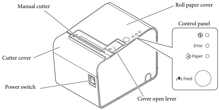
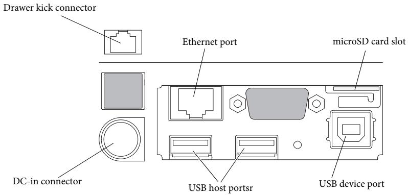
Interface
All the ports and connectors are located on the back of the printer.
Control Panel
①(Power) LED
Lights when the power is on, and is off when the power is off.
Error LED
Off when the printer is online, lights when the printer is offline, and flashes when an error occurs.
Paper LED
Lights when roll paper is out.
Feed button
Feeds the roll paper.
Setup
Installing the Printer Horizontally or Vertically
You can install the printer horizontally (with the paper exit on top) or vertically (with the paper exit at the front).
When installing the printer vertically, attach the included control panel label to the printer case, and install it on a flat surface.

Removing or Installing the Paper Guide
Install or remove the paper guide to match the width of the roll paper in use.
A 58 mm paper guide is installed.
- When using a roll paper that is 58 mm wide, use the printer as it is.
- When using a roll paper that is 80 mm wide, remove the installed guide.
- When using a roll paper that is 40 mm wide, remove the installed guide, and install the included 40 mm paper guide.

CAUTION:
Changing to a roll paper that is wider than the roll paper in use can cause decreased print quality.
Removing the Paper Guide
- Open the roll paper cover using the cover open lever.
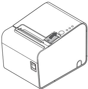
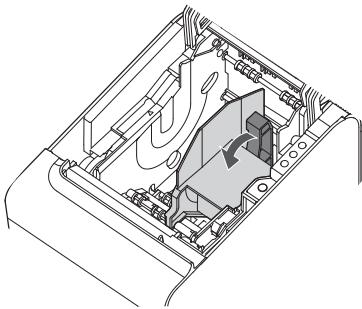
- Pull the paper guide in the direction of the arrow in illustration while pulling the lever of the paper guide to remove it.
Installing the Paper Guide

CAUTION:
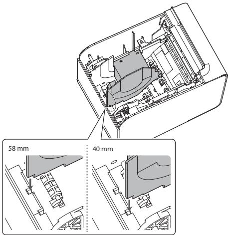
Installation position of the paper guide varies depending on the width of the paper guide. Do not install the 58 mm paper guide in the position for the 40 mm paper guide.
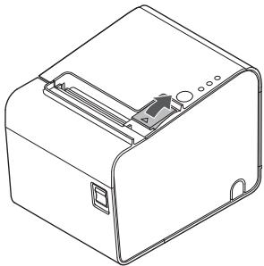
- Open the roll paper cover using the cover open lever.
- Align the projection of the paper guide with the hole in the roll paper holder.
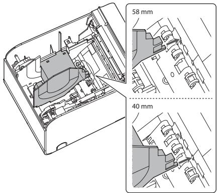
- Align the corner of the paper guide with the notch in the roll paper holder.
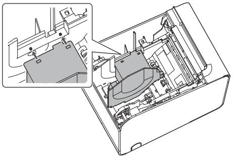
- Align 2 holes in the paper guide with 2 projections of the roll paper holder.
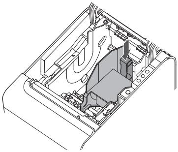
- Push the lever of the paper guide down until the paper guide clicks into place.
Connecting Cables
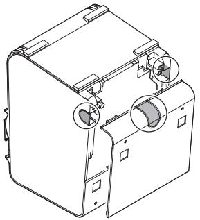
Remove the printer cover to connect the cable.
Removing the Cover
- Place the printer as shown in the illustration, and pull the cover in the direction of the arrow to remove it.
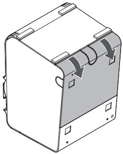
- Break off by hand any of the three portions indicated by circles in the illustration to pass the cables through.
- Connect the cables to the printer.
- Attach the cover while passing the cables through the holes.
Connecting the AC Adapter
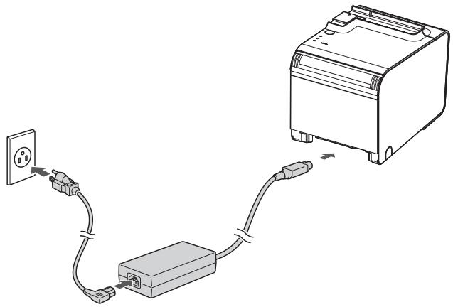
Follow the steps below to connect the AC adapter.
- Firmly insert the DC connector of the AC adapter all the way into the DC-in connector on the printer.
- Firmly insert the connector of the AC cable all the way into the AC inlet on the AC adapter.
- Firmly insert the plug all the way into the grounded wall outlet.
- Set the AC adapter so that its label side is facing down.
Connecting External Devices
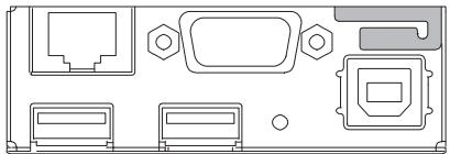
If you connect external devices, connect each cable to the port/connector on the back of the printer. (☐ "Interface" on page 6)

CAUTION:
☐ When connecting external devices to the USB ports, follow the precautions below.
- Confirm the rated current of the external devices by checking the descriptions on the devices or manuals. Connect the external devices only when their total rated current is less than 600 mA. Do not use a device whose rated current is unclear. - Use UL-approved external devices (only for North American users).
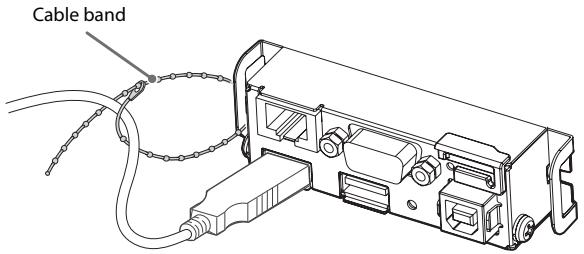
When connecting the USB cables, pass the cables through the cable band to prevent them from coming off.
When using the printer, make sure the protective cover fits firmly into place.
When Ethernet cables are installed outdoors, make sure devices without proper surge protection are cushioned by being connected through devices that do have surge protection. Otherwise, the devices can be damaged by lightning.

Note:
Connecting the optional Wireless LAN Cable Set (OT-WL Series) to the USB port enables the wireless LAN connection. While connecting via wireless LAN, keep the Ethernet cable unconnected to the printer.
Basic Operations
Turning Power On/Off
Press the power switch to turn on or off the power.
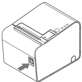

Note:
It takes approximately 30 seconds after the printer is turned on until it is ready for printing.
Opening the roll paper cover
Pull the cover open lever to open the roll paper cover.
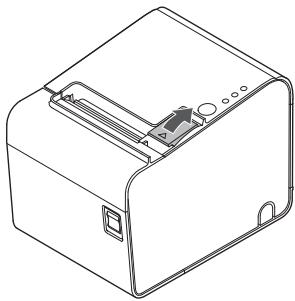

CAUTION:
Do not open the roll paper cover during printing. Doing so may cause an injury or the product to no longer work properly.
Installing or Replacing the Roll Paper

CAUTION:
Be sure to use the specified roll paper. (See "TM-L90-i Specifications" on page 20.) If you change the paper type from linerless label paper to thermal roll paper, cleaning around the paper path is recommended. (See "Cleaning Inside the Printer" on page 15.)
- Open the roll paper cover using the cover open lever.
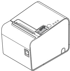
- Remove the used roll paper core if there is one.
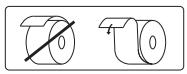
- Insert a roll of paper in the correct direction.
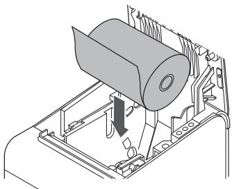

- Pull out a small amount of paper, aligning the paper with the paper guides on both sides.
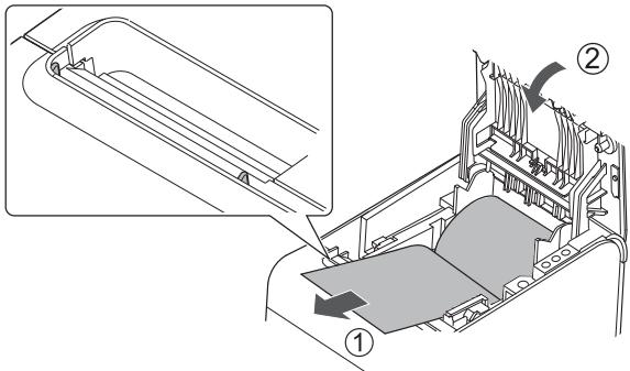
- Be sure to close the roll paper cover completely by pushing on the middle of the cover. When the printer is powered on, the paper will feed and cut automatically.
Cleaning
Cleaning the Printer Case
When cleaning the printer case, be sure to turn off the printer, and wipe the dirt off the printer case with a dry or damp cloth.

CAUTION:
Never clean the product with alcohol, benzine, thinner, or other such solvents. Doing so may damage or break the parts made of plastic and rubber.
Cleaning Inside the Printer
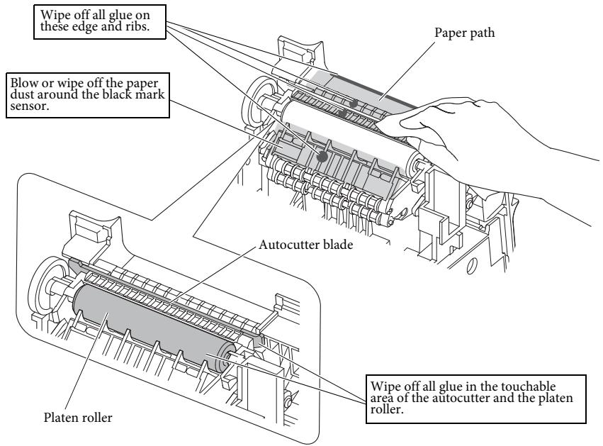
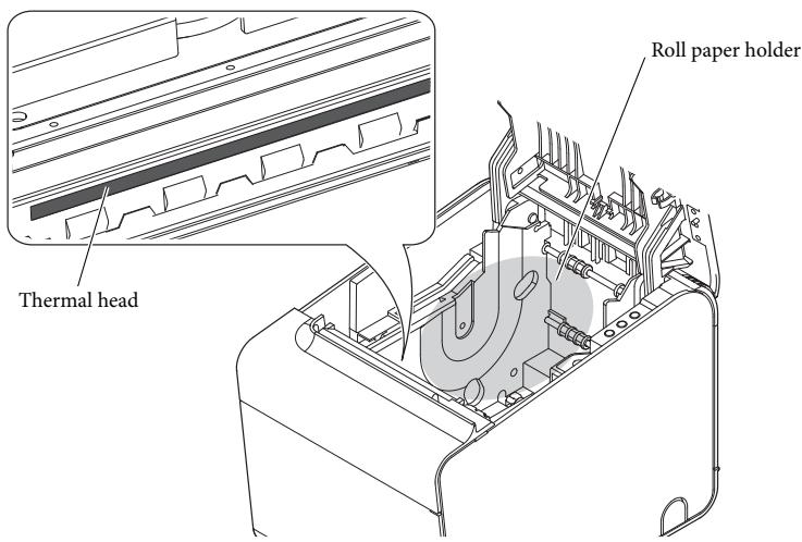
When print quality is deteriorated, clean the paper path (such as the autocutter blade, platen roller, thermal head, and the roll paper holder).
To clean these parts, turn off the printer, unplug the AC cable, open the roll paper cover, and remove paper dust, adhesive glue, or other foreign substances with a cotton swab or cloth moistened with an alcohol solvent (ethanol or IPA).
If paper dust adheres around the black mark sensor, blow or wipe it off to keep the printer operating normally.
For the locations of each part, see the illustration.

CAUTION:
☐ If adhesive glue is attached, be sure to wipe it all off. ☐ Take care not to injure your fingers on the manual cutter when cleaning. ☐ Before turning on the printer after cleaning, allow alcohol on the printer to dry completely.


CAUTION:
The thermal head can be very hot after printing. Be careful not to touch it and let it cool before cleaning. Do not damage the thermal head by touching it with your fingers or any hard object.
Running a Self-test
In self-test mode, the printer will perform a series of internal diagnostics and then provide a listing of printer settings.
Having a printed self-test in hand when calling for technical support can help speed up the troubleshooting process.
Use the following procedure to start a self-test.
- Close the roll paper cover.
- While pressing the Feed button on the control panel, turn on the printer. (Keep pressing the Feed button until the printer starts printing.) The printer prints out the various printer states.
- When all printer states have been printed, make sure that the following message is displayed and the Paper LED flashes: "If you want to continue SELF-TEST printing, please press Feed button." The printer is now in the self-test wait mode.
- To start a test print, press the Feed button when the printer is in the self-test wait mode.
- Check that the following has been printed: "*** completed ***". This indicates that the printer has been initialized and has made the transition to normal mode.
Resetting the Printer
Certain error conditions can be reset by turning the printer off and then back on.
Not all error conditions can be reset using this method. (See "Troubleshooting" on page 18.)
Troubleshooting
Power LED does not light
Check whether the AC adapter is correctly connected. (See "Connecting the AC Adapter" on page 11.)
Error LED on or flashing
Check to see that the roll paper cover is closed and check the Paper LED. Close the cover or replace the roll paper if necessary. If the Paper LED is on, check whether the roll paper is correctly installed and if any roll paper remains. (See "Installing or Replacing the Roll Paper" on page 14.) If the printer has been printing a lot, the thermal head may be hot. Wait for the head to cool. Printing will resume automatically. Open the roll paper cover, and check to see if the paper is jammed. If a paper jam occurs or if the roll paper cover will not open, see the section below. Turn the printer off and back on. If the LED is still flashing, notify your manager. The printer may require servicing.
Printout is faint
When printout is faint, adhesive glue or another foreign substance may be present on the thermal head, platen roller, or paper path of the printer.
In such case, first clean the thermal head by following the instructions described in "Cleaning Inside the Printer" on page 15.
If the print quality does not improve, clean the platen roller and paper path of the printer by following the instructions described in "Cleaning Inside the Printer" on page 15.
Printed character size is not appropriate for 40 mm/58 mm width paper
When using 40 mm/58 mm width roll paper, if the printed character size is not appropriate or if the printout does not fit within the paper width, the paper guide may not be installed correctly. (See "Installing the Paper Guide" on page 8.)
Paper jam
Turn off the power and open the roll paper cover to remove the jammed paper. After that, install the roll paper correctly. If the roll paper cover will not open, see the section below.
If glue or another foreign substance is present on the autocutter blade, platen roller, or the paper path, a paper jam is likely to occur. (See "Cleaning Inside the Printer" on page 15.)
The roll paper cover will not open
Follow the steps below when the roll paper cover will not open.
- Turn off the printer.
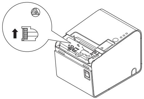
- Insert a tool such as a screwdriver into the slots on both sides of the printer, and lift the cover in the direction of the arrow to remove it.
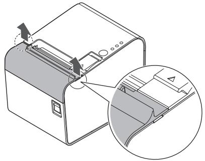
- Turn the knob in the direction of the arrow, by using a ballpoint pen or tweezers, until you see a triangle mark in the opening.
TM-L90-i Specifications
| 80 mm paper width | 58 mm paper width | 40 mm paper width | ||
| Print method | Thermal line printing | |||
| Dot density | 203 dpi × 203 dpi [dots per 25.4 mm {1"}] | |||
| Print width | 72 mm {2.84"}, 576 dot positions | 52.5 mm {2.07"}, 420 dot positions | 35 mm {1.38"}, 280 dot positions | |
| Paper dimensions | 79.5 ± 0.5 × max. Φ102 mm{3.13 ± 0.02 × 4"} | 57.5 ± 0.5 × max. Φ102 mm{2.26 ± 0.02 × 4"} | 40.0 ± 0.5 × max. Φ102 mm{1.57 ± 0.02 × 4"} | |
| Paper type | Normal / LFC Full Coated | Thermal paper: NTP080-80Linerless label paper: 9023 - 0839 (12 roles) | Thermal paper: NTP058-80 | Linerless label paper: 9023-1055 (12 roles) |
| LFC Lane Coated | Linerless label paper: 9023 -1274 (6 roles)9023 -1253 (12 roles) | Linerless label paper: 9023 -1823 (12 roles)9023 -1397 (30 roles) | Linerless label paper: 9023 -1275 (6 roles)9023 -1257 (12 roles) | |
| Interface | Ethernet | × 110BASE-T/100BASE-TX | ||
| VGA | do not use | |||
| USB (host) | × 2USB 2.0, Type A5 V, 500 mA*1 | |||
| USB (device) | × 1USB 2.0 High speed, Type B | |||
| micro SD card | × 1 | |||
| Drawer kick | × 1 | |||
| Power supply*2 | DC+24 V ± 7% | |||
| Current consumption | Approximately 1.8 A | |||
| Temperature | Normal / LFC Full Coated | Operating: 5 to 45°C {41 to 113°F}Storage: -10 to 50°C {14 to 122°F} (except for paper) | ||
| LFC Lane Coated | Operating: 5 to 35°C {41 to 95°F}Storage: -10 to 50°C {14 to 122°F} (except for paper) | |||
| Humidity | Normal / LFC Full Coated | 10 to 90% | ||
| LFC Lane Coated | 20 to 80% | |||
| Overall dimensions | 140 × 203 × 148 mm {5.51 × 7.99 × 5.83"} (W × D × H) | |||
| Weight (mass) | Approximately 1.9 kg {4.19 lb} | |||
dpi: dots per 25.4 mm (dots per inch) *1: 500 mA at maximum for one port. 600 mA at maximum for total of the two ports. *2: Be sure to use a safety-standards-applied power source that meets the following specifications. Rated output: 24 V, 2.0 to 10.0 A Maximum output: 240 VA or less
Memory switch settings
Memory switches can be set with the memory switch setting utility.
| Paper width | 40mm | 58mm | 80mm | |||||
| Characters per line | Font A | 40 | 23 | 42 | 30 | 42 | 44 | 48 |
| Font B | 40 | 31 | 60 | 40 | 55 | 57 | 64 | |
| Auto scaling function | MSW 6-2 | ON | OFF | ON | OFF | - (Do not care) | ||
| 80mm cpl settings | MSW 6-4 | - (Do not care) | ON | ON | OFF | |||
| MSW 6-5 | - (Do not care) | ON | OFF | OFF | ||||
| Select of 40mm or 58mm | MSW 6-8 | OFF | ON | - (Do not care) | ||||
Appendix
Downloading Drivers, Utilities, and Manuals
The latest versions of drivers, utilities, and manuals can be downloaded from one of the following URLs.
For customers in North America, go to the following web site: http://www.epson.com/support/
For customers in other countries, go to the following web site: https://download.epson-biz.com/?service=pos
Open Source Software License
This product uses open source software in addition to Epson proprietary software.
For information on the open source software used in this product, see the following URL.
http://xxx.xxx.xxx.xxx/licenses.htm
For “xxx.xxx.xxx.xxx” in the above URL, input your printer’s IP address.
Restriction of Use
When this product is used for applications requiring high reliability/safety, such as transportation devices related to aviation, rail, marine, automotive, etc.; disaster prevention devices; various safety devices, etc.; or functional/precision devices, etc.; you should use this product only after giving consideration to including fail-safes and redundancies into your design to maintain safety and total system reliability. Because this product was not intended for use in applications requiring extremely high reliability/safety, such as aerospace equipment, main communication equipment, nuclear power control equipment, or medical equipment related to direct medical care, etc., please make your own judgment on this product's suitability after a full evaluation.
Caution
No part of this publication may be reproduced, stored in a retrieval system, or transmitted in any form or by any means, electronic, mechanical, photocopying, recording, or otherwise, without the prior written permission of Seiko Epson Corporation. No patent liability is assumed with respect to the use of the information contained herein. While every precaution has been taken in the preparation of this book, Seiko Epson Corporation assumes no responsibility for errors or omissions. Neither is any liability assumed for damages resulting from the use of the information contained herein.
Neither Seiko Epson Corporation nor its affiliates shall be liable to the purchaser of this product or third parties for damages, losses, costs, or expenses incurred by purchaser or third parties as a result of: accident, misuse, or abuse of this product or unauthorized modifications, repairs, or alterations to this product, or (excluding the U.S.) failure to strictly comply with Seiko Epson Corporation's operating and maintenance instructions.
Seiko Epson Corporation shall not be liable against any damages or problems arising from the use of any options or any consumable products other than those designated as Original Epson Products or Epson Approved Products by Seiko Epson Corporation.
EPSON is a registered trademark of Seiko Epson Corporation.
Exceed Your Vision is a registered trademark or trademark of Seiko Epson Corporation. All other trademarks are the property of their respective owners and used for identification purpose only. Product information is subject to change without due notice.
NOTICE: The contents of this manual are subject to change without notice.
© Seiko Epson Corporation 2016. All rights reserved.
French
Note:
CAUTION:
http://www.epson.com/support/
https://download.epson-biz.com/?service=pos


- STANDARDS AND APPROVALS
- WARNING
- FCC COMPLIANCE STATEMENT FOR AMERICAN USERS
- FOR CALIFORNIA CUSTOMERS ONLY
- ENGLISH
- IMPORTANT SAFETY INFORMATION
- KEY TO SYMBOLS
- CAUTION
- NOTE
- SAFETY PRECAUTIONS
- WARNING: - IF THIS PRODUCT PRODUCES SMOKE, A STRANGE ODOR, OR UNUSUAL NOISE, IMMEDIATELY UNPLUG THE AC CABLE, AND THEN CONTACT YOUR DEALER OR AN EPSON SERVICE CENTER FOR ADVICE. CONTINUED USE MAY LEAD TO FIRE OR ELECTRIC SHOCK. - DO NOT USE THIS PRODUCT WITH ANY VOLTAGE OTHER THAN THE SPECIFIED ONE. DOING SO MAY LEAD TO FIRE OR ELECTRIC SHOCK. - DO NOT CONNECT THE CABLES IN WAYS OTHER THAN THOSE SPECIFIED IN THE MANUALS. DIFFERENT CONNECTIONS MAY CAUSE EQUIPMENT DAMAGE OR FIRE. - DO NOT USE THIS PRODUCT WHERE INFLAMMABLE FUMES OF GASOLINE, BENZINE, THINNER, OR OTHER INFLAMMABLE LIQUIDS MAY BE IN THE AIR. DOING SO MAY CAUSE AN EXPLOSION OR FIRE. - DO NOT USE AEROSOL SPRAYERS CONTAINING FLAMMABLE GAS INSIDE OR AROUND THIS PRODUCT. DOING SO MAY CAUSE FIRE. - IF WATER OR OTHER LIQUID SPILLS INTO THIS PRODUCT, IMMEDIATELY UNPLUG THE AC CABLE, AND THEN CONTACT YOUR DEALER OR AN EPSON SERVICE CENTER FOR ADVICE. CONTINUED USE MAY LEAD TO FIRE OR SHOCK. - DO NOT ALLOW FOREIGN OBJECTS TO FALL INTO THIS PRODUCT. PENETRATION BY FOREIGN OBJECTS MAY LEAD TO FIRE OR ELECTRIC SHOCK. - NEVER ATTEMPT TO REPAIR THIS PRODUCT YOURSELF. IMPROPER REPAIR WORK CAN BE DANGEROUS. - NEVER DISASSEMBLE OR MODIFY THIS PRODUCT. TAMPERING WITH THIS PRODUCT MAY RESULT IN INJURY, FIRE, OR ELECTRIC SHOCK
- WHEN YOU REMOVE PRINTED PAPER
- CAUTION LABELS
- UNPACKING
- INTERFACE
- CONTROL PANEL
- ①(POWER) LED
- ERROR LED
- PAPER LED
- FEED BUTTON
- SETUP
- INSTALLING THE PRINTER HORIZONTALLY OR VERTICALLY
- REMOVING OR INSTALLING THE PAPER GUIDE
- REMOVING THE PAPER GUIDE
- INSTALLING THE PAPER GUIDE
- CONNECTING CABLES
- REMOVING THE COVER
- CONNECTING THE AC ADAPTER
- CONNECTING EXTERNAL DEVICES
- BASIC OPERATIONS
- TURNING POWER ON/OFF
- OPENING THE ROLL PAPER COVER
- INSTALLING OR REPLACING THE ROLL PAPER
- CLEANING
- CLEANING THE PRINTER CASE
- CLEANING INSIDE THE PRINTER
- RUNNING A SELF-TEST
- RESETTING THE PRINTER
- TROUBLESHOOTING
- POWER LED DOES NOT LIGHT
- ERROR LED ON OR FLASHING
- PRINTOUT IS FAINT
- PRINTED CHARACTER SIZE IS NOT APPROPRIATE FOR 40 MM/58 MM WIDTH PAPER
- PAPER JAM
- THE ROLL PAPER COVER WILL NOT OPEN
- MEMORY SWITCH SETTINGS
- APPENDIX
- DOWNLOADING DRIVERS, UTILITIES, AND MANUALS
- OPEN SOURCE SOFTWARE LICENSE
- RESTRICTION OF USE
- FRENCH
Brand : EPSON
Model : TM-L90
Category : Thermal receipt printer