
CHAUFFE EAU BLINDE 150L - Water heater CHAFFOTEAUX - Free user manual and instructions
Find the device manual for free CHAUFFE EAU BLINDE 150L CHAFFOTEAUX in PDF.
| Product type | Electric storage water heater |
| Brand | Chaffoteaux |
| Model | CHAUFFE EAU BLINDE 150L |
| Capacity | 150 liters |
| Dimensions (H x Ø) | 1160 x 505 mm |
| Net weight | 38 kg |
| Power supply | 230 V single-phase or 400 V three-phase (depending on model) |
| Power (consumption) | 6,689 kWh/24h (profile M) |
| Tank type | Enameled steel baked at high temperature |
| Anti-corrosion protection | Magnesium anode (armored range) |
| Heating element | Armored immersion heating element |
| Hydraulic connection | Cold water inlet and hot water outlet: G 3/4" |
| Service pressure | 7 bar (max.) |
| Adjustable temperature | Up to 70 °C (adjustable thermostat) |
| Electrical protection | IPX4 (volume 1 bathroom), 30 mA residual-current circuit breaker required |
| Installation | Wall-mounted vertical, minimum distance floor/ceiling: 50 cm / 5 cm |
| Recommended maintenance | Annual draining, magnesium anode check, descaling |
| Tank warranty | 5 years |
| Electrical parts warranty | 2 years |
| Compliance | CE, Low Voltage and EMC directives |
| Essential accessories | Safety group (EN 1487), dielectric fittings |
Frequently Asked Questions - CHAUFFE EAU BLINDE 150L CHAFFOTEAUX
User questions about CHAUFFE EAU BLINDE 150L CHAFFOTEAUX
0 question about this device. Answer the ones you know or ask your own.
Ask a new question about this device
Download the instructions for your Water heater in PDF format for free! Find your manual CHAUFFE EAU BLINDE 150L - CHAFFOTEAUX and take your electronic device back in hand. On this page are published all the documents necessary for the use of your device. CHAUFFE EAU BLINDE 150L by CHAFFOTEAUX.
USER MANUAL CHAUFFE EAU BLINDE 150L CHAFFOTEAUX
Instructions for installation and maintenance


Cher client,
Thank you for choosing this appliance! Welcome to the ever-growing family of satisfied customers using our products throughout the world.
We are sure that you will benefit – and gain great satisfaction - from using this appliance. We would advise that you read this manual carefully, and that you keep it in a safe and easily accessible place.
This booklet must be retained for the entire working life of the appliance to which it refers.
Booklet in English see page 45.
The manufacturer reserves the right to make all modifications deemed necessary for the improvement of the product.
AVERTISSEMENTS DE SECURITE
PROfessional TECH - HPC - ACC
3.Raccordement hydraulique
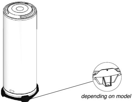
2.2.d. STAB models on base structures
This appliance is fitted with a base structure which is fixed to the product while it is still at the company. Position the appliance on a perfectly flat and level surface.

Picture 11.- Model on base structure
Picture 12 - Model on base structure
3. Water connection
- The operating pressure is indicated on the data plate of the water heater (see water heater).
- Connection with materials synthesis PER are prohibit: flood risk
To connect the tank on plastic pipe "PER" installation existent, intercalate on the out-let (hot water) a copper pipe with minimum longer 50 cm to avoid any damage.
The connection of a water heater to copper piping must be performed using a dielectric connection. These dielectric connections are available as an optional extra or as standard, depending on the model purchased.
If you only have one dielectric connector, you must fit it to the hot water outlet!
Picture 14 - A dielectric connector
- When the input pressure of the network is greater than 4.5 bar, a pressure reducer must be installed upstream of the safety assembly.
- If the water systems have the following features:
small pipes;
taps with ceramic plates / mixer taps;
a "ram stabilising" device or a domestic hot water expansion vessel suited to the system must be installed as close as possible to the taps.
Advice
We recommend that a shut-off valve is installed upstream from the safety assembly.
See pictures 6, 7, 8, 9, 10, and 12.
4. Electrical connection
4.1. Important considerations
THE WIRING DIAGRAM IS STUK ONTO THE APPLIANCE: USE IT AS A REFERENCE GUIDE.
4.2. The models with TM and TR designation are three-phase versions (TRI):
These three-phase devices are wired in 400 V TRI by the manufacturer. They can be connected 230V TRI or 230V single-phase (see wiring diagram on the device).
4.3. The models with MT designation are three-phase devices:
These devices are wired 230V single phase by the manufacturer and can be connected to 230V TRI or 400V TRI (See wiring diagram on the device) The 500 liters floor standing model is wired 400V TRI by the manufacturer. The electrical connection of the device is made exclusively on the thermostat's terminals or on the device's terminal board.
ANY DIRECT CONNECTION TO THE HEATING ELEMENT IS HAZARDOUS ANS IS STRICTLY PROHIBITED.
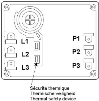
Thermal safety device
- Cut off the electricity supply before performing any work on the appliance.
- This appliance can be used by children aged from 8 years and above and persons with reduced physical, sensory or mental capabilities or lack of experience and knowledge if they have been supervision or instruction concerning use of the appliance in a safe way and understand the hazards involved. Children shall not play with the appliance. Cleaning and user maintenance shall not be made by children without supervision.
- The elements comprising the packaging must be removed from the reach of children as they can constitute a source of danger.
- The installation of the water heater, appliance preparation, maintenance work and repair work may only be carried out by qualified personnel. These individuals must act in accordance with current national legislation. In particular, all regulations relating to water heaters must be fully observed.
- CAUTION: The appliance must never be powered when it is empty, as this could damage the electrical components.
Fill the boiler by opening the water inlet valve on the safety assembly.
Open the hot water tap so that the air cushion which has accumulated inside the water heater may be expelled.
Close the hot water tap as soon as water begins to come out of it.
Make sure the base and the attachment seals are watertight Where necessary, re-tighten the bolts on the base (recommended between 18 and 20Nm - dynamometric spanner) or the attachments.
- The water heater must be fitted with a safety assembly which conforms to current national legislation(EN 1487), with pressure 7 bars-0.7MPa, connected to the cold water pipe.
The safety assembly must be fitted as close as possible to the cold water inlet of the water heater and THE PASSAGE OF WATER MUST NEVER BE PREVENTED by any type of accessory.
If, for technical reasons, the safety assembly cannot be installed with a direct connection to the cold water inlet, (max 50 cm) the installed connection must be rigid and must always be made using material which is able to withstand pressures of at least 7 bar and high temperatures.
The drainage outlet of the safety assembly must never be obstructed and must be connected to a vertical drainage pipe with a diameter which is at least equal to that of the appliance connection piping, with a funnel which creates an empty space of at least 20 mm leading outwards. This piping must be installed in a room which is not subject to icy conditions, sloping downwards.
Use always new pipes to connect the appliance at water network.
- Due to the expansion of water during the heating stage, dripping from the safety assembly (up to 3% of the nominal capacity) is normal. Please read the instructions
for the safety assembly. An expansion vessel may be installed in order to prevent this leakage.
- Activate the tap and the valve on the safety assembly every month so as to prevent limescale from building up. Replace the safety assembly at least once every 5 years or, if necessary, more frequently.
- The appliance and its safety assembly must be installed in a room which is not subject to freezing conditions.
When performing maintenance work, the following should be provided:
- a free space of at least 50~cm in front of the plastic cover so that the electrical components may be accessed;
- direct access to the safety assembly.
- For safety reasons, if away from the premises, users must turn the hydraulic and electric circuits off, as well as drain the appliance.
Cut off the electricity supply before performing any work on the appliance.
Shut off the cold water supply at the inlet.
Open the hot water tap to draw water.
Open the emptying valve on the safety assembly and the water will flow out of the drainage hole.
- To prevent burns from occurring, use suitable mixers which ensure that the temperature does not exceed 50^ at the drawing points and 60^ for the kitchen.
- Recommendations for installation in a bathroom environment:
The water heater installation in the bathroom must be adapted in accordance with national rules and standards in force (NFC 15-100, RGIE, etc.).
The system must be fitted with a switch which has an opening of 3mm between contacts. The circuit must be protected by fuses or switches which are calibrated according to the power of the water heater.
The electric water heater must be connected in accordance with European regulations and the connections must always conform to current national legislation. The line must be protected by a 30mA differential switch.
The electrical connection of a fixed appliance should be performed using a suitable rigid wire with an appropriate cross-section and a green/ yellow earth wire: please consult current national legislation relating to electrical systems (the minimum requirement will be 3 × 2.5 mm^2 singlephase and 4 × 2.5 mm^2 three-phase for a power level of up to 3000 W ).
- CAUTION: the appliance MUST be earthed!
Do not use piping for an earth connection.
- If the appliance is supplied with rechargeable batteries, these must be removed before the appliance is discarded and disposed of in a safe manner. The batteries must be removed from the support structure located in the area which can be accessed from underneath the plastic cover.
- The manufacturer shall not be held liable for any damage caused to persons, animals or other things, by unprofessional or improper installation, or by failure to comply
Anti-legionella recommendations (European standard CEN/TR 16355)
Information
Legionella is a small bacterium, of stick-like form, and is found naturally in fresh water.
Legionnaire's disease is a serious pulmonary infection caused by inhalation of the Legionella pneumophila bacterium and other species of Legionella. The bacterium is frequently to be found in the plumbing of houses, hotels and water used in A/C and air cooling systems. The most effective measure against infection is to prevent the bacterium proliferating in water circuits.
European standard CEN/TR 16355 provides guidelines for preventing the proliferation of Legionella in drinking water systems, without substituting applicable local legislation.
General recommendations
"Conditions favourable to the proliferation of Legionella". The following conditions are favourable to the proliferation of Legionella:
- Water temperature in the range 25 - 50^ . To reduce the proliferation of Legionella, the water temperature be kept with these limits to prevent them growing or reduce their growth to a minimum. If this is not possible, the drinking water system must be sanitised thermally;
- Stagnant water. To prevent water stagnating for a long time, the drinking water system must be flushed or made to run abundantly at least once a week;
Nutrients, biofilms and sediment in the circuit, including boilers, etc. Sediment may promote the proliferation of Legionella and should be regularly eliminated from water storage devices, boilers and expansion/holding tanks (for instance, once a year).
As regards storage heater like the present, if:
1) the appliance is switched off for several months at a time or
2) the water temperature is kept constant in the range 25 - 50^ ,
the Legionella bacterium may grow inside the tank. If such circumstances, to reduce the proliferation of the bacterium, one must run a thermal sanitisation cycle.
This cycle is suited to use in domestic hot water systems and complies with the guidelines for the prevention of Legionella given in Table 2 of standard CEN/TR 16355 (see below).
Table 2 - Types of hot water system
| Separate hot and cold water | Mixed hot and cold water | |||||||||
| No storage | Storage | No storage uptime of the mixer valves | Storage uptime of the mixer valves | No storage uptime of the mixer valves | ||||||
| No circulation of hot water | Circulation of hot water | No circulation of mixed water | Circulation of mixed water | No circulation of mixed water | Circulation of mixed water | No circulation of mixed water | Circulation of mixed water | No circulation of mixed water | Circulation of mixed water | |
| Ref. in Enclosure C | C.1 | C.2 | C.3 | C.4 | C.5 | C.6 | C.7 | C.8 | C.9 | C.10 |
| Temperature | - | ≥50°C e | in storage heater a | ≥50°C e | Thermal disinfection d | Thermal disinfection d | in storage heater a | ≥50°C eThermal disinfection d | Thermal disinfection d | Thermal disinfection d |
| Stagnation | - | ≥3 I b | - | ≥3 I b | - | ≥3 I b | - | ≥3 I b | - | ≥3 I b |
| Sediment | - | - | remove c | remove c | - | - | remove c | remove c | - | - |
| a Temperature ≥55°C all day or at least 1h a day ≥60°C.b Volume of water contained in the pipes between the circulation system and the most distant tap.c Remove the sediment from the storage heater as required by local conditions, but no less frequently than once a year.d Thermal disinfection for 20 minutes at 60°C, for 10 minutes at 65°C or 5 minutes at 70 °C at all delivery points at least once a week.e The water temperature in the circulation circuit may not fall below 50°C.- Not required | ||||||||||
However, the thermal disinfection cycle does not kill all Legionella bacteria in the storage tank. It follows that if the water temperature setting is less than 55^ , the Legionella bacterium infection may reoccur.
Caution: the water temperature in the tank can cause immediate serious burns. Children, disabled persons and the aged are particularly at risk of burns. Check the water temperature before taking a bath or shower.
TECHNICAL CHARACTERISTICS
For the technical specifications, refer to the nameplate (the nameplate is located next to the water intake/outlet pipes).
The power consumption data in the table and the other information given in the Product Data Sheet (Enclosure A to this manual) are defined in relation to EU Directives 812/2013 and 814/2013. The products without the label and the data sheet for water heaters and solar devices, stipulated in regulation 812/2013, are not intended to be used in such assemblies. Products equipped with a regulator knob have the thermostat positioned in the
This appliance is conforming with the international electrical safety standards IEC 60335-1 and IEC 60335-2-21. The CE marking of the appliances tests its conformity to the following EC Directives, of which it satisfies the essential requisites :
- LVD Low Voltage Directive: EN 60335-1, EN 60335-2-21, EN 60529, EN 62233, EN 50106.
- EMC Electro-Magnetic Compatibility: EN 55014-1, EN 55014-2, EN 61000-3-2, EN 61000-3-3.
- RoHS2 Risk of Hazardous Substances: EN 50581.
- ErP Energy related Products: EN 50440.
| Vertical Installation | |||||||||
| Model | Capacity [L] | Product range | Qelec [kWh] | Charging profile | Supply | V40 [L] | ηwh | **Static losses Qpr [Wb/24a a 60°C] | **Water production at 40°C [L] |
| Ø470 VERT | 50 | THER | 6,665 | M | energized | 65 | 36.1% | 0.79 | nc |
| STEA/ACC | 6,679 | M | 65 | 36.0% | 0.72 | nc | |||
| 75 | THER | 6,688 | M | energized | 90 | 36.0% | 0.99 | 136 | |
| STEA/ACC | 6,550 | M | 85 | 36.6% | 0.96 | 129 | |||
| Ø505 VERT | 100 | THER | 12,883 | L | energized | 143 | 37.0% | 1.31 | 176 |
| STEA | 12,883 | L | 148 | 37.0% | 1.31 | 180 | |||
| 150 | THER | 6,689 | M | Off Peak | 222 | 36.0% | 1.75 | 276 | |
| STEA | 6,689 | M | 237 | 36.0% | 1.75 | 277 | |||
| 200 | THER | 12,883 | L | Off Peak | 251 | 37.0% | 2.15 | 359 | |
| STEA | 12,883 | L | 336 | 37.0% | 2.15 | 372 | |||
| Ø530 VERT | 100 | THER | 12,502 | L | energized | 143 | 37.9% | 1.06 | 176 |
| HPC/ZEN/STEA/ACC | 12,442 | L | 148 | 38.0% | 1.06 | 180 | |||
| 150 | THER | 6,601 | M | Off Peak | 237 | 36.4% | 1.35 | 276 | |
| HPC/ZEN/STEA | 6,578 | M | 222 | 36.5% | 1.35 | 277 | |||
| 200 | THER | 12,612 | L | 351 | 37.6% | 1.76 | 359 | ||
| HPC/ZEN/STEA | 12,506 | L | 336 | 37.9% | 1.76 | 372 | |||
| Ø560 VERT | 100 | THER | 12,840 | L | energized | 145 | 37.1% | 1.03 | 177 |
| HPC/QUIE/STEA | 12,792 | L | 140 | 37.2% | 1.05/1.03* | 176/172* | |||
| 150 | THER | 6,681 | M | Off Peak | 220 | 36.0% | 1.48 | 276 | |
| HPC/QUIE/STEA | 6,669 | M | 230 | 36.1% | 1.48/1.41* | 271 | |||
| 200 | THER | 12,865 | L | 334 | 37.0% | 1.73 | 370 | ||
| HPC/QUIE/STEA | 12,766 | L | 332 | 37.3% | 1.73 | 372 | |||
| 250 | STEA | 12,821 | L | Off Peak | 317 | 37.1% | 1.97 | 455 | |
| Horizontal Installation | |||||||||
| Ø505 HORB | 75 | THER | 6,683 | M | energized | 69 | 36.0% | nc | nc |
| Ø560 HORB | 100 | STEA | 6,353 | M | energized | 121 | 37.5% | 1.65 | 165 |
| THER | 6,246 | M | 108 | 38.0% | 1.65 | 165 | |||
| 150 | STEA | 12,798 | L | 196 | 37.2% | 2.25 | 231 | ||
| THER | 12,552 | L | 177 | 37.8% | 2.25 | 231 | |||
| 200 | STEA | 13,126 | L | 231 | 37.0% | 2.68 | 318 | ||
| THER | 13,126 | L | 197 | 37.0% | 2.68 | 318 | |||
| Ø505 HORD | 75 | THER | 6,531 | M | energized | 96 | 36.7% | nc | nc |
| Ø530 HORD | 100 | THER | 6,687 | M | 158 | 36.0% | 1.33 | 178 | |
| 150 | THER | 12,882 | L | 222 | 37.0% | 1.65 | 279 | ||
| 200 | THER | 12,882 | L | 301 | 37.0% | 1.97 | 365 | ||
| Ø570 HORD | 100 | THER | 6,687 | M | energized | 160 | 36.0% | 1.32 | 187 |
| 150 | THER | 12,882 | L | 263 | 37.0% | 1.68 | 281 | ||
| 200 | THER | 12,882 | L | 303 | 37.0% | 2.02 | 367 | ||
| Floor Standing Installation | |||||||||
| Ø570 STABLE | 200 | THER | 12,883 | L | Off Peak | 330 | 37.1% | 1.98 | 356 |
| HPC/STEA | 12,883 | L | 333 | 37.0% | 1.98 | 349 | |||
| 250 | THER | 12,883 | L | 373 | 37.0% | 2.36 | 469 | ||
| STEA | 12,883 | L | 370 | 37.0% | 2.36 | 460 | |||
| 300 | THER | 12,883 | L | 473 | 37.0% | 2.61 | 525 | ||
| STEA | 12,883 | L | 473 | 37.0% | 2.61 | 515 | |||
| 250 | HPC | 12,879 | L | 423 | 37.0% | 2.17 | 458 | ||
| 270 | HPC | 12,667 | L | 430 | 37.5% | 2.3 | 505 | ||
| 300 | HPC | 12,808 | L | 524 | 37.2% | 2.45 | 563 | ||
| 300 | QUIE/ZEN | 12,883 | L | 473 | 37.0% | 2.61 | 525 | ||
- value for the range HPC/PTEC (d560)
* value according to the specifications LCIE 103-14D
nc = not concerned
INTRODUCTION
1. Introduction to the product
1.1. Regulations relating to transportation, storage and recycling
- The appliance must be transported in accordance with the pictograms printed on the packaging.
- The appliance must be transported and stored in dry conditions where it will not be subjected to freezing.
- The EU Directive 2012/19/UE sets out the obligation to perform separated waste collection and to recycle all electrical and electronic equipment.

The "crossed-out dustbin" symbol on the appliance indicates that when the product is no longer in good working condition, it should not be disposed of in the same manner as normal household waste. Instead, it should be taken to a separated waste collection centre which deals with electrical and electronic equipment or reclaimed by the distributor when a new appliance has been purchased to replace it.
Separated waste collection, which ensures the appliance is recycled once it has reached the end of its life cycle, helps to avoid any negative effects on the environment and encourages the recycling of the individual materials used to manufacture the appliance.
To find out more about existing waste collection centres, please contact the waste collection service in your local area, or the shop from which the appliance was originally purchased.
- The packaging protects the water heater from any damage which may occur during transportation. We use materials which have been specifically selected in order to help protect the environment. We invite you to take these materials to the nearest recycling centre or the nearest recyclable materials collection point.
1.2. Dimensions
See page 2.
All our appliances conform to the EMC Directive 89/336/EEC.
All our boilers are constructed using steel which conforms to the regulation NF A36-301.
The protective internal coating in our boilers is made using enamel which has been vitrified at a high temperature.
1.3. THER armoured range
1.3.a. Definition of the range
Heating element: Immersion heating element
Anti-corrosion protection: Enamelled boiler + magnesium anode
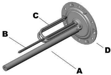
Picture 1- Immersion heating element + magnesium anode
1.3.b. Technical features
See page 6.
1.4. STEA steatite range
1.4.a. Definition of the range
Heating element: Steatite heating element
located inside a bush
Anti-corrosion protection: Enamelled boiler +
magnesium anode
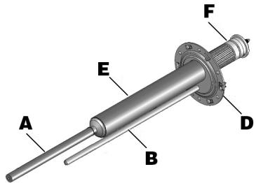
Picture 2- Steatite heating element + magnesium anode
1.4.b. Technical features
See page 6.
1.5. Professional TECH PTEC steatite range - HPC
1.5.a. Definition of the range
Heating element: Steatite heating element located inside a bush
Anti-corrosion protection: Enamelled boiler + PROfessional TECH anode - HPC
The exclusive PROfessional TECH system solution is an anodic anti-corrosion electronic protection system with a modulated current. It ensures maximum durability in terms of the boiler used in the water heater, regardless of whether more or less aggressive water is used. The electronic circuit creates a difference in potential between the boiler and the titanium electrode, so that optimal boiler protection is guaranteed, thereby preventing its corrosion.
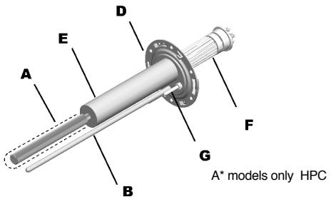
Picture 3- Steatite heating element + PROfessional TECH anode
1.5.b. Technical features See page 6.
INSTALLATION
1. Legal obligations and recommendations relating to product installation
Before installing this appliance, please read the instructions contained in this manual carefully. Failure to observe these instructions may lead to the guarantee becoming void.
- All product installation and maintenance work must only be performed by qualified professionals. Current national legislation must be observed. In particular, all regulations relating to water heaters must be fully observed.
- The manufacturer shall not be held liable for any damage caused by unprofessional or improper installation, or by failure to comply with the instructions contained in the user manual.
- If the appliance is installed in a room which is just above an inhabited space (a loft, attic, false ceiling, etc.), insulate the piping and fit a retention tank with water drainage. Connection
to the sewage system is compulsory in all instances.
Advice To avoid excessive energy consumption, we recommend that the water heater is positioned as close as possible to the hot water drawing points (recommended distance: no greater than 8 metres).
Recommendation when installing in the bathroom:
The water heater installation in the bathroom must be adapted in accordance with national rules and standards in force (NFC 15-100, RGIE, etc.).
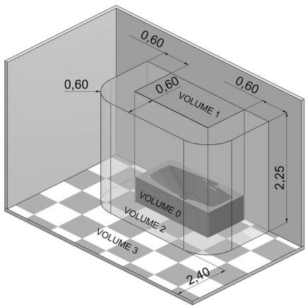
Volume classifications:
Volume 0: This is the interior volume of the bathtub or shower tray.
Volume 1: This is the volume outside that bathtub or shower tray and is limited on the one side by the vertical cylindrical surface circumscribed to the edge of the bathtub or shower tray, and on the other by the horizontal plane at 2.25m from the bottom of the bath or shower base.
Volume 2: This is the volume external to volume 1. It is limited by the vertical cylindrical surface 0.60m from the edge of the bathtub or shower tray and limited by a horizontal plane at 2.25m above the bottom of the bathtub or shower tray.
Volume 3: This is the volume external to volume 2. It is limited by the vertical cylindrical surface 2.40m from volume 2 and limited by a horizontal plane at 2.25m above the bottom of the bathtub or shower tray.
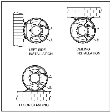
Authorised water heater fixing zones:
A: Magnesium anode / B: Spike / C: Immersion heating element / D: Plate / E: Bush / F: Steatite heating element / G: PROfessional TECH anode.
1 «This regulation applies in France and the installer must keep up to date with all subsequent modifications. For installation in other countries, please refer to applicable local regulations.».
Fixed, low voltage water heaters are permitted in volume 1 as long as they have maximum protection level (IPX4). Please note: horizontal type water heaters, installed as high up as possible in volume 1 are permitted for France only.
Only fixed water heaters which have a protection degree of at least IP 24 are permitted within the protection volume (B).
2. Installing the product
2.1. Material required
2.1.a. Tools and materials which should be provided
If the wall cannot withstand the weight of the water heater a support or a ceiling fixing kit.
If you wish to fix a horizontal model to a wall or to a ceiling a set of fixing straps.
For the seal : hemp/tow and sealing paste or a seal for connections to be screwed in, depending on the model.
Spirit level.
If the water heater is fitted with fixing brackets:
For each fixing bracket 2 rawplugs and 2 bichromate concrete screws, Fischer M10, M12 or M14 type.
Material necessary for drilling with M10, M12 or M14 diameter.
Dynamometric spanner.
Nuts with M10, M12 or M14 diameter.
Washer with M10, M12 or M14 diameter.
2.1.b. Accessories
Indispensable accessories:
Safety assembly (suited to the model).
Dielectric connection(s).
If the water pressure is greater than 4.5 bar a pressure reducer.
Others:
Cut-off valve.
Domestic hot water expansion vessel.
Mixer which helps to prevent the risk of burns, as the temperature does not exceed 50^ at the drawing points and 60^ in the kitchen (this is a legal obligation in France).
2.2. Assembly
2.2.a. General instructions for the fixing brackets Fix the support bracket(s) to a load-bearing wall using suitable fastening bolts measuring 10mm in diameter and flat steel washers measuring a minimum of 24mm and a maximum of 30mm in (external) diameter.
IMPORTANT: MAKE SURE THAT THE NUT IS WELL TIGHTENED
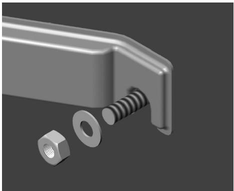
Picture 5 - Fitting the fixing bracketInstallation values
2.2.b. VERT Vertical wall-fitted model
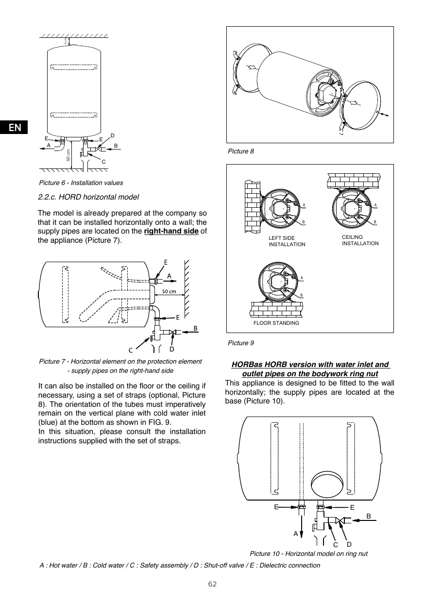
Position the appliance at least 50~cm from the floor and at least 5cm from the ceiling to facilitate maintenance work. (Picture 6)
This model can also be installed on a support (optional), but it absolutely must be fixed to a load-bearing wall with the upper fixing bracket.
Make sure that the installed support is suitable for the model of water heater and diameter in question, and that it is correctly assembled and installed.
Advice We recommend the use of a support which is compatible with the products designed by this manufacturer.
Advice Use the installation template printed on the packaging of the water heater.
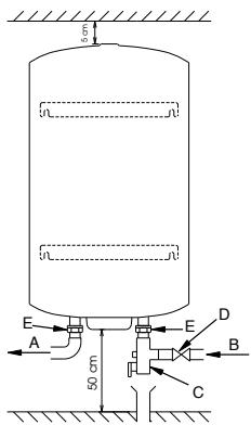
Picture 6 - Installation values
2.2.c. HORD horizontal model
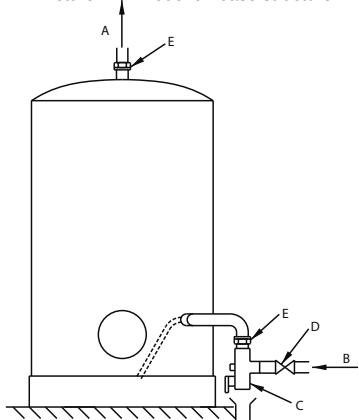
The model is already prepared at the company so that it can be installed horizontally onto a wall; the supply pipes are located on the right-hand side of the appliance (Picture 7).
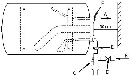
Picture 7 - Horizontal element on the protection element supply pipes on the right-hand side
It can also be installed on the floor or the ceiling if necessary, using a set of straps (optional, Picture 8). The orientation of the tubes must imperatively remain on the vertical plane with cold water inlet (blue) at the bottom as shown in FIG. 9.
In this situation, please consult the installation instructions supplied with the set of straps.
Picture 8
Picture 9
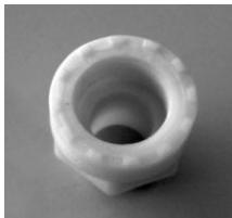
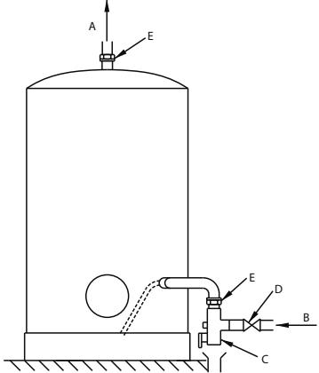
HORBas HORB version with water inlet and outlet pipes on the bodywork ring nut
This appliance is designed to be fitted to the wall horizontally; the supply pipes are located at the base (Picture 10).
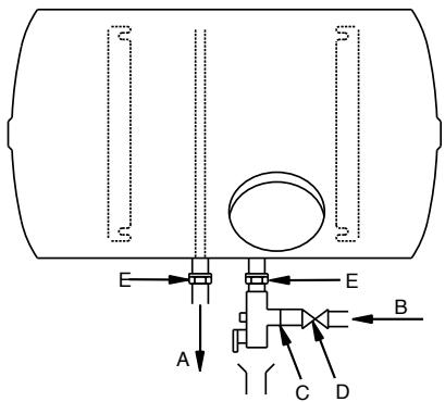
Picture 10 - Horizontal model on ring nut
A : Hot water / B : Cold water / C : Safety assembly / D : Shut-off valve / E : Dielectric connection
2.2.d. STAB models on base structures
This appliance is fitted with a base structure which is fixed to the product while it is still at the company. Position the appliance on a perfectly flat and level surface.
Picture 11.-Model on base structure
Picture 12 - Model on base structure
3. Water connection
- The operating pressure is indicated on the data plate of the water heater (see water heater).
2. Connection with materials synthesis PER are prohibit: flood risk
To connect the tank on plastic pipe "PER" installation existent, intercalate on the out-let (hot water) a copper pipe with minimum longer 50~cm to avoid any damage.
The connection of a water heater to copper piping must be performed using a dielectric connection. These dielectric connections are available as an optional extra or as standard, depending on the model purchased.
If you only have one dielectric connector, you must fit it to the hot water outlet!
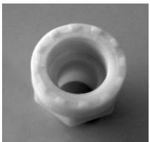
Picture 14 - A dielectric connector
- When the input pressure of the network is greater than 4.5 bar, a pressure reducer must be installed upstream of the safety assembly.
- If the water systems have the following features:
small pipes;
taps with ceramic plates / mixer taps;
a "ram stabilising" device or a domestic hot water expansion vessel suited to the system must be installed as close as possible to the taps.
Advice We recommend that a shut-off valve is installed upstream from the safety assembly.
See pictures 6, 7, 8, 9, 10, and 12.
4. Electrical connection
4.1. Important considerations
THE WIRING DIAGRAM IS STUK ONTO THE APPLIANCE: USE IT AS A REFERENCE GUIDE.
4.2. The models with TM and TR designation are three-phase versions (TRI):
These three-phase devices are wired in 400 V TRI by the manufacturer. They can be connected 230V TRI or 230V single-phase (see wiring diagram on the device).
4.3. The models with MT designation are three-phase devices:
These devices are wired 230V single phase by the manufacturer and can be connected to 230V TRI or 400V TRI (See wiring diagram on the device) The 500 liters floor standing model is wired 400V TRI by the manufacturer. The electrical connection of the device is made exclusively on the thermostat's terminals or on the device's terminal board.
ANY DIRECT CONNECTION TO THE HEATING ELEMENT IS HAZARDOUS ANS IS STRICTLY PROHIBITED.
4.4.1 PROfessional TECH (PTEC)
The boiler protection anode is controlled by an electronic device powered at the network current or using a battery designed for systems operating in day/night mode, in order to keep the boiler protected during the day. Correct operation of the protection system REQUIRES A PERMA-NENT POWER SUPPLY (network or batteries). The appliance cannot, in fact, be left without a power supply for more than 48 hours.
4.4.2 HPC
The boiler protection anode is controlled by an electronic device powered at the network current.
In case of system operating in day/night mode, during the night the protection is guaranteed by the PROfessional TECH anode, while during the day the protection is guaranteed by the magnesium anode.
ATTENTION: The anti-corrosion system cannot stay without power supply more than 1 week.
4.5 Day/night or permanent power supply: operating principle
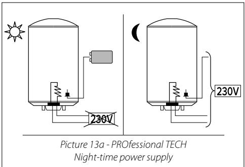
4.5.1 Products PROfessional TECH (PTEC)
(1) Night-time power supply + batteries
Heating element Night-time power supply (exclusive or dual timer schedule) (Picture 13a).
Anode PROfessional TECH Night-time power supply + day-time operation with batteries.*
- Electric water heaters, designed for a night-time power supply, are fitted with Ni-MH batteries which are charged every night, thereby protecting the boiler during the day.
CAUTION: The batteries do not have an indefinite lifespan: it makes good sense to replace them once they have been used for one or two years.
In order to guarantee full boiler protection, any faulty batteries must be replaced. If the batteries are not replaced, the guarantee will become void.
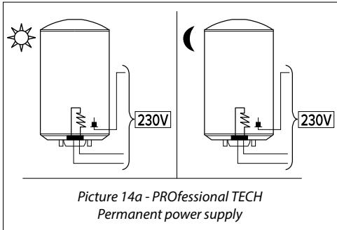
(2)Permanent power supply
Heating element and anode PROfessional TECH 一 Continuous power supply (Picture 14a).
Operation without battery.
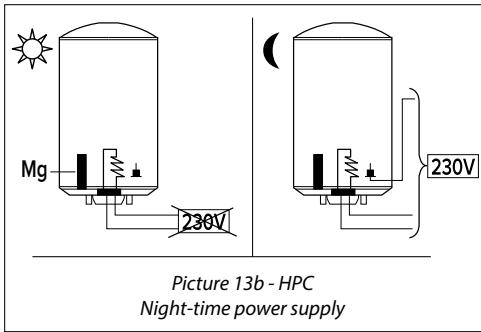
4.5.2 Products HPC
① Night-time power supply
Heating element Night-time power supply (exclusive or dual timer schedule) (Picture 13b).
Anode PROfessional TECH Night-time power supply.*
- In products HPC, the protection is however guaranteed during the day by the magnesium anode.
(2)Permanent power supply
Heating element and anode PROfessional TECH Continuous power supply (Picture 14b).
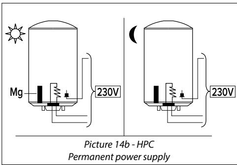
IMPORTANT: ONLY FOR WATER HEATER TRI PROFESSIONAL TECH MUST ALWAYS BE SUPPLIED WITH 230V OR 400V AC.
IN CASE OF 400V TRIPHASE NETWORK SUPPLY: PROfessional TECH CONNECTION BETWEEN 2 PHASES 400V.
IN CASE OF 230V TRIPHASE OR 230V MONOPHASE NETWORK SUPPLY: PROFESSIONAL TECH CONNECTION BETWEEN PHASES 230V (Follow electrical wiring described on electrical wiring tag)
OPERATION
1. Introduction
1.1. User considerations
- The installation of the water heater is the responsibility of the purchaser.
- This appliance is not intended for use by persons (including children) with reduced physical, sensory or mental capabilities, or lack of experience and knowledge, unless they have been given supervision or instruction concerning use of the appliance by a person responsible for their safety. Children should be supervised to ensure that they do not play with the appliance.
- The end user is responsible for recycling the appliance once it can no longer be used. For further information, please consult the introduction of this booklet 1.1. - Regulations relating to transportation, storage and recycling.
2. Operating advice
2.1.Temperature adjustment
We recommend the thermostat is not set to its maximum position, in order to avoid limescale build-up and prevent burns. It is nevertheless essential to find a suitable compromise so as to avoid bacterial proliferation while trying to prevent the water heater from experiencing unnecessary limescale build-up.
On the other hand, in order to prevent burns, a suitable mixer should be used so that the temperature does not exceed 50^ at any of the drawing points. This is a compulsory regulation in France.
Advice
When using a mixer at a drawing point, we recommend that the temperature is set to approximately 60^ .
2.2. Maintenance
Empty the appliance annually (twice a year if the water has been treated with a softening agent) in order to:
- check the condition of the magnesium anode;
- remove all deposits inside the boiler.
Contact your installer.
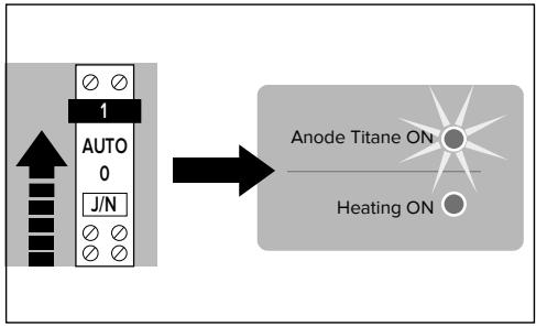
2.3. Indicator lights
2.3.1 Products PROfessional TECH steatite range
The boiler protection anode is controlled by an electronic device powered at the network current or using a battery designed for systems operating in day/night mode, in order to keep the boiler protected during the day.
The PROfessional TECH system cannot be left without a power supply for over 48 hours
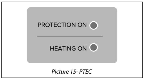
Indicator light PROTECTION ON: light ON

Light OFF = anti-corrosion protection defect : replace the battery NIMH 9V. If the defect goes on, contact your installer.
Indicator light: HEATING ON
Light ON= under heating
Light OFF = out of heating
If connected to the mains with a dual timer schedule or exclusive night-time schedule (only for models with battery), the green indicator light switches on but is very weak for the first 48 hours in accordance with the charge status of the battery. Check the indication light after 48 hours of operation.
Advice In order to guarantee full boiler protection (green light illuminated), any faulty batteries must be replaced. If the batteries are not replaced, the guarantee will become void. It makes good sense to replace them once they have been used for one or two years.
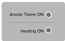
2.3.2 Products HPC
The boiler protection anode is controlled by an electronic device powered at the network current, in order to keep the boiler protected during the night.
In products HPC, the protection is however guaranteed during the day by the magnesium anode.
ATTENTION: The anti-corrosion system cannot stay without power supply more than 1 week.
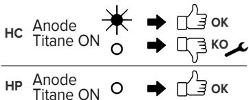
BRANCHEMENT HC/HP
In case of installation with night-time power supply only, in order to guarantee the boiler protection,
AT LEAST ONCE PER YEAR check regularly the functioning of the Protection light, forcing the electrical connection in manual mode ON.
MAINTENANCE AND REPAIRS
1. Maintenance
Empty the appliance annually (twice a year if the water has been treated with a softening agent) in order to:
- check the condition of the magnesium anode;
- remove all deposits inside the boiler.
We strongly recommend that the performance of the water softener is checked regularly.
The residual hardness cannot be lower than 15^ for THER, STEA, and PTEC products. Instead the residual hardness cannot be lower than 8^ for HPC products.
1.1. Emptying
Cut off the electricity supply before performing any work on the appliance.
Shut off the cold water supply at the inlet.
Open the hot water tap to draw water.
Open the emptying valve on the safety assembly and the water will flow out of the drainage hole.
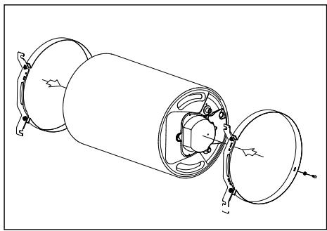
1.2. Build-up removal - Checking the anode
Empty the appliance (see above).
Remove the protection element and unscrew the base (some residual water may leak out).
Clean the boiler: without using metal objects or chemical agents, remove any build-up on electrical elements or on the bush (steatite), on the corresponding casing and on the base of the boiler.
If a magnesium anode is used, check its condition: the magnesium anode is consumed progressively in accordance with the water quality, in order to prevent corrosion of the boiler. If the diameter is smaller than 15mm (for the armoured range) / 10mm (for the steatite range), or if the total volume is lower than 50% of the initial volume, the anode should be replaced.
Use a new seal every time the base is replaced after being removed.
When screwing in the bolts again, use a "cross-tightening" technique. The tightening torque should be between 18 and 20Nm .
| CAUSES AND SOLUTIONS | PROBLEM | ||||||||||||||||||||||||||||||||||||||||||||||||||||||||||||||||||||||||||||||||||||||||||||||||||||||
EN
① Replacing or resetting the thermostat
If the thermostat is deactivated, reset it and establish the cause (short-circuit, faulty thermostat, etc.).
CAUTION: Every thermostat is designed to be reset a maximum of two or three times only!
② Replacing the heating element
Check the Ohmic value of the heating element and, if necessary, replace it. A null or an infinite value indicates that the heating element must be replaced.
Armoured range
The appliance must be emptied before the armoured heating element may be replaced.
Steatite range - PROfessional TECH steatite range
It is not necessary to empty the appliance before replacing the heating element. During a Technical Assistance procedure for a steatite water heater, it is absolutely necessary to replace the plastic separator between the thermostat and the heating element in the water heater as this guarantees the correct operation of the appliance.
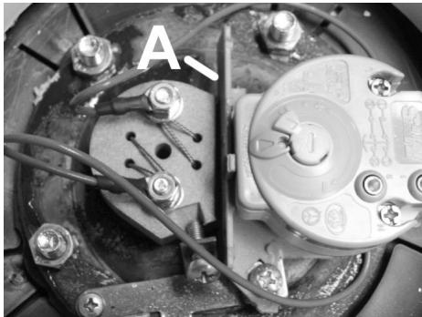
Picture 17 - Plastic separator / A: plastic separator
③ Replacing the electronic circuit
PROfessional TECH PTEC steatite range
Before performing any work, make sure you have isolated the appliance from the electricity supply network. The replacement of the electronic circuit is a very simple process. After removing the plastic protection:
Disconnect the storage cell (press-fit connector on the storage cell).
Disconnect the 2 wires running from the electronic circuit to the power supply terminal board.
Disconnect the fast coupling connector with the false movement protection device which links the circuit to the boiler and the electrode.
Disconnect the electronic circuit from the support (plastic material clips on the corners).
Replace the faulty circuit with a new one.
Repeat the procedure described above in the reverse order.
④ Replace the battery.
PROfessional TECH steatite range
The storage cell is replaced by disconnecting the press-fit connector and replacing the old storage cell with a new rechargeable one, Ni-Mh 9 volt 150mAh minimum.
Technical Assistance Centre
If the problem persists, please contact our Technical Assistance Centre:
| France Chaffoteaux sas Carré Pleyel 5 Rue Pleyel 93 521 Saint Denis Cedex Tel: 01 55 84 94 94 Fax: 01 55 84 96 10 | Belgium and Luxembourg Ariston Thermo Benelux sa Industrielaan 61, 1070 Brussel 61, Boulevard industriel, 1070 Brussel Tel: 02/333 48 88 Fax: 02/333.48 89 |
Spare parts service
To request spare parts, please contact the relevant Spare Parts Service.
The replacement of electrical parts must be carried out by a professional.
| France Chaffoteaux sas Pièces de rechanges (spare parts) B.P. 45 Tressignaux | Belgium and Luxembourg Ariston Thermo Benelux sa Industrielaan 61, 1070 Brussel 61, Boulevard industriel, 1070 Brussel |
| Tel: 02 96 65 33 33 Fax: 02 96 70 28 59 | Tel: 02/333.48.22 Fax: 02/333.48.49 |
GUARANTEE CONDITIONS
Preface: The following provisions cannot be used to reduce or cancel the statutory claim against hidden defects (art. 1611 and subsequent modification of the Civil code).
Given the technical nature of the product and in order to guarantee the safety and protection of the consumer, the electric water heater must be installed, prepared for operation and regularly serviced by a qualified professional in accordance with the instructions provided in the installation manual and in full compliance with industry standards. The appliance must be used in a normal manner, in compliance with industry standards and in accordance with current legislation and the instructions supplied in the installation manual.
The product is developed and guaranteed for the installation and use in domestic appliances.
For industrial use or non domestic ones, take contact with the manufacturer to insure the guarantee and good working of the product.
Given the technical nature of the product, repairs under guarantee must be performed by an authorised technician. The manufacturer shall not be held liable for repairs performed and parts supplied by other professionals or their authorised technicians.
Breakdowns due to the following conditions are not covered by the guarantee:
Unusual environmental conditions:
Positioning the appliance in a place which is subject to ice or bad weather.
Supplying the appliance with rainwater, well water or water which contains an unusually aggressive content and which does therefore not conform to national regulations or current legislation.
The hardness of the running water must be greater than 12^ .
The use of a softener does not affect our guarantee, on the condition that the softener is correctly calibrated, monitored and subject to regular maintenance. In this case, the residual hardness must be greater than 15^ .
Water pressure greater than 4.5 bar.
Various damages caused by knocks or falls during handling after the appliance has been delivered.
In particular, water damage which could have been prevented if the water heater had been repaired immediately. The guarantee only applies to the water heater and its components, with the exception of all or part of the electrical or hydraulic system of the appliance.
Electricity supply with significant amounts of excess voltage.
A system which does not comply with regulations, current national legislation and which is unprofessional, in particular:
The absence or incorrect installation of the safety assembly.
The installation of a safety assembly which does not conform to current national legislation of the use of a worn-out safety assembly inside a newly-installed water heater.
Modification of the safety assembly adjustment after irregular plumbing work.
The use of a tripod which has not been authorised by the manufacturer, or which has not been installed
according to the instructions given in this manual.
Unusual corrosion due to poor hydraulic connections (direct iron-copper contact); a lack of insulating attachments.
Faulty electrical connection which does not conform to national installation regulations, poor earthing, insufficient wire cross-section, non-adherence to supplied connection diagrams, etc.
Switching the appliance on without filling it up first (dry heating).
Installation without retention tank as recommended in paragraph 1.1.
Appliance installed in a narrow room with inaccessible electrical parts.
The use of spare parts which have not been authorised by the manufacturer.
Insufficient maintenance: the water heater must undergo annual maintenance:
Unusual build-up on the heating elements and the safety devices.
A lack of maintenance in terms of the safety assembly, with resulting excessive pressure.
Bodywork subjected to external violence.
Modification of the original systems without the manufacturer's approval or using spare parts which have not been specified by the manufacturer.
A lack of maintenance in terms of the appliance itself, especially regarding the replacement of the anode when necessary.
No replacement of the batteries in an appliance which uses them, or replacement of rechargeable batteries with batteries which do not conform to the demands listed in this set of instructions.
The guarantee is limited to the replacement or repair of appliances and components which we recognise as being originally faulty. If necessary, the part or product should be returned to one of our factories, only after an agreement is made with our Technical Assistance Centres. All expenses relating to labour, carriage, packaging and handling will be paid for by the user. The replacement or repair of a component inside an appliance may not, in any event, give rise to compensation.
Certificate n. TC-B.60719 valid from 21/11/2013 until 20/11/2016
GUARANTIE
CHAUFFE-EAU ELECTRIQUES CONDITIONS DE GARANTIES
1) The hot water boiler must be installed by a qualified technician according to the rule book, standards in force and the provisions laid out in our technical instructions.
The boiler shall be used normally and be serviced on a regular basis by a specialist.
Under such conditions, our guarantee shall be executed via replacement, if necessary, of the appliance or the free-of-charge supply to our Distributor or Installer of the pieces recognized as being defective by our technical department to the exclusion of labour costs, transport costs, any compensation and prolongation of the guarantee. The guarantee will come into effect on the date of installation, with the invoice relating to the installation constituting proof, in the absence of any documentary evidence, the date upon which the guarantee becomes effective shall be the date of manufacture mentioned on the identification plate mounted on the hot water boiler, with this date being extended by a further 3 months.
The hot water tank is guaranteed for a 5-year period when this concerns a simple, electrical model of 50 to 500 litres; a 3-year guarantee applies to 10, 15, 30 litre tanks, with this also applying to continuous flow hot water boilers, combined hot water boilers, preheater reservoirs.
The electrical components and removable parts are guaranteed for a period of two years.
N.B.: Expenses or damages due to defective installation (for instance: freezing, safety valve not connected to a waste water outlet, no retention tank) or to difficult access shall under no circumstances be charged to the manufacturer.
2) LIMITS OF THE GUARANTEE
The guarantee does not cover defects due to:
Abnormal environmental conditions :
installation in premises subject to freezing or bad weather;
appliance is supplied with rain water, well water or unusually corrosive water and is not in accordance with national regulations in force (e.g.: DTU plumbing 60-1 for France, Royal Decree of 27.04.84 and ERRATA of 21.05.85 for Belgium);
the guarantee is limited to the exchange or repair of the hot water boiler and those component parts which we have acknowledged as having been defective from the start. If necessary, the component part or the boiler will have to be returned to one of our factories but only after prior agreement has been obtained from our technical department. Labour, transport and travel costs shall be paid for by the user. Exchange or repair of a component part shall in no event give rise to a demand for compensation; water pressure (higher than 7 bars);
damage caused by mishandling (impact, falls) after factory delivery;
in particular, water damage which could have been avoided by immediately repairing the hot water boiler. The guarantee applies only to the hot water boiler and its component parts, to the exclusion of any parts relating to the appliance's electrical or hydraulic installation;
power supply with considerable surge voltage.
Any installation which does not comply with the regulations, standards and rule book, in particular :
absence or incorrect installation of a safety valve;
installation of a safety valve which does not comply with the national standards in force (e.g.: NF ANSEAU, TuV,...) and use of a second-hand safety valve in a newly installed hot water boiler.
modifications to the safety valve's adjustment subsequent to breaking the seal;
abnormal corrosion due to incorrect hydraulic connection (direct iron-copper contact);
defective electrical connection which does not comply with national installation standards (e.g.: NF - C 15100, RGIE,...), incorrect earthing of the installation, insufficient cable width, failure to comply with the recommended wiring diagrams, etc. the hot water boiler is switched on before it has been filled with water (dry heating).
Defective maintenance :
abnormal scaling of the heating elements and safety valve;
absence of maintenance of the safety valve, leading to excess pressure (see instructions);
boiler body exposed to external attacks;
modifications to the original equipment without the manufacturer's consent or use of spare parts not referenced by the latter;
absence of maintenance of the appliance, and especially non-replacement of the anodes at the appropriate time (see section V). 3) RECOMMENDATIONS
For regions where the water is very hard, the use of a water softener does not entail waiver of our guarantee provided that the water softener is adjusted in compliance with the manufacturer's instructions, and inspected and serviced on a regular basis. In particular: the water's residual hardness may not be less than 15 F.
4) The provisions laid out in the present terms are in addition to any other rights or benefits the purchaser may be entitled to regarding the legal guarantee for hidden defects, applicable in any case whatsoever, in accordance with article 1641 and following of the Civil Code.
5) LEGAL PROCEEDINGS
All disputes shall be settled by the Commercial Courts in Namur, Belgium.
TECHNICAL DEPARTMENT
For all technical questions, please contact:
EN FRANCE
Chaffoteaux sas Carré Pleyel 5 Rue Pleyel 93521 SAINT DENIS CEDEX

WE MAKE USE OF RECYCLED PAPER
Ariston Thermo SpA
Viale Aristide Merloni 45
60044 Fabriano (AN) Italy
Telefon 0732 6011 - Fax 0732 602331
info.it@aristonthermo.com
www.aristonthermo.com