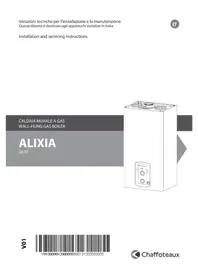
Alixia 24 FF - Boiler CHAFFOTEAUX - Free user manual and instructions
Find the device manual for free Alixia 24 FF CHAFFOTEAUX in PDF.


| Product Type | Gas Boiler |
| Brand | Chaffoteaux |
| Model | Alixia 24 FF |
| Energy Source | Natural Gas / Propane |
| Heating Output | 24 kW |
| DHW Output | 24 kW (instantaneous) |
| Boiler Type | Wall-mounted, Condensing (likely) |
| Dimensions (H x W x D) | 740 x 450 x 345 mm |
| Weight | 38 kg |
| Electrical Supply | 230 V / 50 Hz |
| Electrical Power Consumption | 120 W (typical) |
| Flue Type | Room-sealed (FF - Forced Flue) |
| Water Pressure (Min/Max) | 1.0 / 3.0 bar |
| Max Heating Temperature | 80°C |
| Energy Efficiency Class | A (typical for condensing) |
| Noise Level | ≤ 50 dB(A) |
| Protection Class | IPX4D |
| Safety Features | Flame failure, overheat, frost protection, pump anti-block |
| Maintenance | Annual service by qualified engineer |
| Spare Parts Availability | Available through Chaffoteaux network |
| Warranty | 2 years (standard, may vary) |
Frequently Asked Questions - Alixia 24 FF CHAFFOTEAUX
User questions about Alixia 24 FF CHAFFOTEAUX
0 question about this device. Answer the ones you know or ask your own.
Ask a new question about this device
Download the instructions for your Boiler in PDF format for free! Find your manual Alixia 24 FF - CHAFFOTEAUX and take your electronic device back in hand. On this page are published all the documents necessary for the use of your device. Alixia 24 FF by CHAFFOTEAUX.
USER MANUAL Alixia 24 FF CHAFFOTEAUX
Installation and servicing instructions

C. Ingresso gas 3/4"
| A | B | C | |
| PIGMA / PIGMA GREEN 25 180 166 319 | |||
| PIGMA GREEN 30 180 166 388 | |||
| MIRA C / MIRA C GREEN 25 180 166 319 | |||
| MIRA C GREEN 30 180 166 388 | |||
| ALIXIA | 180 | ||
| INOA 246 232 385 | |||
| TALIA SYSTEM TALIA GREEN SYSTEM 12/15/18/25 | 246 232 388 | ||
| TALIA SYSTEM 30/35 246 232 388 | |||
| TALIA SYSTEM GREEN 30/35 246 232 458 | 232 458 | ||
| TALIA / TALIA GREEN 25 246 232 388 | |||
| TALIA 30/35 246 232 388 | |||
| TALIA GREEN 30/35 246 232 458 | |||
| URBIA / URBIA GREEN 25 246 232 388 | |||
| URBIA 30/35 246 232 388 | |||
| URBIA GREEN 30/35 246 232 458 | |||
| SERELIA / SERELIA GREEN 25 339 325 481 | |||
| SERELIA GREEN 30/35 | 339 325 481 |
a


b


Safety regulations 30
Warnings
Advice for the installer 31
Before installing the appliance
Location of the boiler 32
Planning and carrying out installation
Cleaning the heating system 33
CE labelling
Data plate symbol
Connecting the fl ue 34
Type of boiler-fl ue exhaust connection
Electrical connenctions
Product description
Overall wiew 35
Water circuit diagram
Overall dimension 36
Minimum clearances
Installation Template 37
Installation
Water/Gas Connection 38
Mounting the hydraulic Bar Kit (optional)
Cleaning the heating system
Residual Head of the boiler 39
Instruction for opening the casing and
performing an internal inspection 40
Boiler installation 41
Excessive pressure device
Flue gas exhaust/air suction duct
connection 42
Table of fl ue gas exhaust duct lengths
Typeof air suction/fl ue gas exhaust ducting 43
Electrical connection.... 44
Room Thermostat connection
Connection to a solar heating system
Electrical diagram 45
Commissioning
Ignition procedure 46
Initial procedures
Electricity supply
Filling the hydraulic circuit
Gas supply
Control panel
First Ignition 47
Combustion Analysis
Product of combustion Discharge Monitoring
Settings
Checking the gas settings 48
Adjustment the Maximum Heating power and soft light 49
Ignition Delay adjustment
Table summarising changes 50
Gas changeover
Boiler protection devices....51
Appliance shut-off conditions
Safety shut-off
Operation shutdown
Anti-freeze function
Codes error table 52
Maintenance
General comments 53
Operational test
Draining procedures
Information for the user 54
Technical Information
Technical data 55
Safety regulations

Key to symbols:
△ Failure to comply with this warning implies the risk of personal injury, in some circumstances even fatal
Failure to comply with this warning implies
⚠ the risk of damage, in some circumstances even serious, to property, plants or

animals.
Install the appliance on a solid wall which is not subject to vibration.
Noisiness during operation.
When drilling holes in the wall for installation purposes, take care not to damage any electrical

wiring or existing piping.
Electrocution caused by contact with live wires. Explosions, fires or asphyxiation caused by gas leaking from damaged piping. Damage to existing installations. Flooding caused by water leaking from damaged piping.

Perform all electrical connections using wires which have a suitable section.
Fire caused by overheating due to electrical current passing through undersized cables.
Protect all connection pipes and wires in order to prevent them from being damaged.
Electrocution caused by contact with live wires. Explosions, fi res or asphyxiation caused by gas leaking from damaged
piping. Flooding caused by water leaking from damaged piping.
Make sure the installation site and any systems to which the appliance must be connected comply with the applicable norms in force.
Electrocution caused by contact with live wires which have been installed incorrectly. Damage to the appliance caused by improper operating conditions.

Use suitable manual tools and equipment (make sure in particular that the tool is not worn out and that its handle is fixed properly); use them correctly and make sure they do not fall from a height. Replace them once you have finished using them.
Personal injury from the falling splinters or fragments, inhalation of dust, shocks, cuts, pricks and abrasions. Damage to the appliance or surrounding objects caused by falling splinters, knocks and incisions.
Use electrical equipment suitable for its intended use (in particular, make sure that the power supply cable and plug are intact and that the parts featuring rotary

or reciprocating motions are fastened correctly); use this equipment correctly; do not obstruct passageways with the power supply cable, make sure no equipment could fall from a height. Disconnect it and replace it safely after use.
Personal injury caused by falling splinters or fragments, inhalation of dust, knocks, cuts, puncture wounds, abrasions, noise and vibration. Damage to the appliance or surrounding objects caused by falling splinters, knocks and incisions.

Make sure any portable ladders are positioned securely, that they are suitably strong and that the steps are intact and not slippery and do not wobble when someone climbs them. Ensure someone provides supervision at all times.
Personal injury caused by falling from a height or cuts (stepladders shutting accidentally).
Make sure any rolling ladders are positioned securely, that they are suitably strong, that the steps are intact and not slippery and that the ladders are fitted with handrails on either side of the ladder and parapets on the landing.
Personal injury caused by falling from a height.
During all work carried out at a certain height (generally with a difference in height of more than two
metres), make sure that parapets are used to surround the work area or that individual harnesses are used to prevent falls. The space where any accidental fall may occur should be free from dangerous obstacles, and any impact upon falling should be cushioned by semi-
A rigid or deformable surfaces.
Personal injury caused by falling from a height.
Make sure the workplace has suitable hygiene and sanitary conditions in terms of lighting, ventilation
∧ and solidity of the structures.
Personal injury caused by knocks, stumbling etc.
Protect the appliance and all areas in the vicinity of the work place using suitable material.
△ Damage to the appliance or surrounding objects caused by falling splinters, knocks and incisions.
Handle the appliance with suitable protection and with care.
⚠️ Damage to the appliance or surrounding objects from shocks, knocks, incisions and squashing.
During all work procedures, wear individual protective clothing and equipment.
Personal injury caused by electrocution, falling splinters or fragments, inhalation of dust, shocks, cuts, puncture wounds, abrasions, noise and vibration.
△ Place all debris and equipment in such a way as to make movement easy and safe, avoiding the formation of any piles which could yield or collapse.
Damage to the appliance or surrounding objects from shocks, knocks, incisions and squashing.
All operations inside the appliance must be performed with the necessary caution in order to avoid abrupt contact with sharp parts.
Personal injury caused by cuts, puncture wounds and abrasions.
⚠️△ Reset all the safety and control functions affected by any work performed on the appliance and make sure they operate correctly before restarting the appliance.
Explosions, fi res or asphyxiation caused by gas leaks or an incorrect fl ue gas exhaust. Damage or shutdown of the appliance caused by out-of-control operation.
Before handling, empty all components that may contain hot water, carrying out any bleeding if necessary.
Personal injury caused by burns.
Descale the components, in accordance with the instructions provided on the safety data sheet of the
△△ product used, airing the room, wearing protective clothing, avoid mixing different products, and protect the appliance and surrounding objects.
Personal injury caused by acidic substances coming into contact with skin or eyes; inhaling or swallowing harmful chemical agents. Damage to the appliance or surrounding objects due to corrosion caused by acidic substances.
If you detect a smell of burning or smoke, keep clear of the appliance, disconnect it from the electricity supply, open all windows and contact the technician.
Personal injury caused by burns, smoke inhalation, asphyxiation.

Advice for the installer
The installation and first ignition of the boiler must be performed by qualified personnel in compliance with current national regulations regarding installation, and in conformity with any requirements established by local authorities and public health organisations.
After the boiler has been installed, the installer must ensure that the end user receives the declaration of conformity and the operating manual, and should provide all necessary information as to how the boiler and the safety devices should be handled.
This appliance is designed to produce hot water for domestic use.
It must be connected to a heating system and a distribution network for domestic hot water, both of which must be compatible with the appliance's performance and power levels.
It is strictly forbidden to use the appliance for purposes other than those specified. The manufacturer shall not be held liable for any damage due to improper, incorrect or unreasonable use or due to failure to comply with the indications outlined in this manual.
Installation, maintenance and all other interventions must be carried out in full conformity with current legal regulations and any instructions provided by the manufacturer. Incorrect installation can harm persons or animals and damage possessions; the manufacturer shall not be held liable for any damage in such cases.
In the event of faults and/or malfunctions, switch the appliance off and shut off the gas valve. Do not attempt to perform any repairs yourself but contact a qualified professional instead.
Prior to performing any maintenance or repair work on the boiler, make sure you have disconnected it from the electricity supply by switching the external bipolar switch to the "OFF" position.
Any repairs must be carried out by a qualified professional using original spare parts only.
Failure to comply with the above-mentioned recommendations may jeopardise the appliance's safety and void the manufacturer's liability.
In the event of any maintenance or other structural work in the immediate vicinity of the ducts or flue gas exhaust devices and their accessories, turn the appliance off by switching the external bipolar switch to the "OFF" position and shut off the gas valve.
Once work is completed, ask a qualified technician to check the efficiency of the ducting and devices.
Whenever the external parts of the appliance must be cleaned, turn the boiler off and put the external switch to the "OFF" position.
Use a damp cloth soaked in soapy water to clean the appliance.
Do not use aggressive detergents, insecticides or toxic products.
Complying with current legislation allows for operating the appliance in a safe, environmentally-friendly and cost-efficien manner.
When using kits or optional accessories, ensure that only original CHAFFOTEAUX parts are used.
Before installing the appliance:
- Avoid installing the appliance in areas where the combustion air has high levels of chlorine (e.g. pool areas) and/or other hazardous products such as ammonia (e.g. hairdresser's shops), alkaline agents (e.g. dry cleaners), etc.
- Make sure that the boiler is equipped for operation with the type of gas available (read the information on the packaging label and on the boiler data plate).
- Check the packaging labels and the data plate on the appliance to verify whether the boiler is intended for the country where it is to be installed, and that the gas category for which the boiler was designed is among the categories approved in the country where it will be used.
- The gas supply piping must be manufactured and sized according to the specific regulations and must comply with the boiler's maximum power output; also ensure that the shut-off valve is suitably size
and properly connected.
- Prior to installing the appliance, we recommend carefully cleaning the gas piping to remove any residues that may jeopardise the boiler's operation.
- Check that the maximum water mains pressure does not exceed 6 bar; should it exceed this level, a pressure reducing valve must be installed.
- Water treatment solutions are required whenever water hardness levels exceed 20°f.
Recommendations:
A lightning protection system must be implemented if the area housing the appliance is exposed to lightning strikes (e.g. isolated installation at the end of power supply lines, etc.).
Our warranty is subject to this condition.
- Never install the boiler above cooking hobs in kitchens, above ovens and, generally, above any source of greasy steam, as this may alter the correct operation of the boiler as a result of possible clogging.
- Ensure that the wall and fixing elements are sufficiently resistant to withstand the boiler's weight (weight: approximately 45 kg).
• Take the necessary precautions to limit any undesired acoustic effects.
Warning :
So that the normal operation of the boiler is not compromised, the place in which it is installed must be suitable with regard to the operating limit temperature value and the appliance should be protected so that it does not come into direct contact with atmospheric agents.
PLANNING AND CARRYING OUT INSTALLATION
Domestic hot water circuit.
A water treatment device is required for water hardness levels above 25 TH.
Main heating circuit.
Heating circuit flow rate: when deciding on the piping dimensions, take into account a minimum flow rate of 300 l/h, with valves shut.
Anti-corrosion measures.
Possible malfunctions due to corrosion may occur when the elements making up the circuit have different characteristics.
To avoid such problems, we recommend using a corrosion inhibitor.
Take all the necessary precautions to ensure that the treated water does not have aggressive characteristics.
Old circuits: after fi tting a decanter on the fl ow return and on the lower point, the circuit must be suitably treated.
We recommend adding bleed devices on all radiators, on the circuit's high points and on the low points of discharge valves.
Cleaning the heating system
Where the boiler is used in conjunction with an older system, various substances and additives may be present in the water and these could have an adverse effect on the operation and durability of the new boiler. Before replacing the old boiler, you must arrange for the system to be cleaned thoroughly in order to eliminate any residue or dirt which could compromise the correct operation of the water heater. Make sure the capacity of the expansion vessel is suited to the amount of water contained in the system.
WARNING
No infl ammable items should be left in the vicinity of the boiler.
Make sure the installation site and any systems to which the appliance must be connected are fully compliant with the current applicable legislation.
If dust and/or aggressive vapours are present in the room in which it is to be installed, the appliance must operate independently of the air inside the room.
CE labelling
The CE mark guarantees that the appliance conforms to the following directives:
- 90/396/CEE relating to gas appliances
- 2004/108/CEE relating to electromagnetic compatibility
- 92/42/CEE relating to energy efficiency
- 2006/95/CEE relating to electrical safety
Data plate synbol

Legend :
- Brand
- Manufacturer
- Boiler model - Serial number
- Commercial reference
- certification number
-
Destination country - gas category
-
Gas setting
-
Installation type
-
Electrical data
-
Maximum domestic hot water pressure
-
Maximum heating pressure
-
Boiler type
-
NOx class / Efficiency
-
Input rating nominal heating
-
Power ouputheating
-
DHW specific flow rate
-
Boiler output efficiency
-
Input rating nominal DHW
-
Gases which may be used
-
Temperature ambiante de fonctionnement
-
Max. central heating temperature
-
Max. domestic hot water temperature
Connecting the Flue
The boiler is designed to operate in B mode (by drawing air from the room) and in C mode (by drawing air from outside).
When installing an exhaust system be careful when handling the seals, in order to avoid fl ue gas leaking into the air circuit.
Horizontally-installed piping must have a downward incline of 3% so as to avoid the build-up of condensate.
When type B installation is used, the room in which the coiler is installed must be ventilated using a suitable air inlet which complies with current legislation. In rooms where corrosive vapours may be present (for example, laundry rooms, hair studios, rooms where galvanic processes take place, etc.) it is important that type C installation is used, with air for combustion drawn from outside. In this way the boiler is protected from the effects of corrosion.
When implementing coaxial suction/exhaust systems the use of authentic accessories is obligatory.
The fl ue gas exhaust ducting must not be in contact with or placed near flammable materials, and must not cross building structures or walls made using flammable material.
When replacing an old boiler, the ventilation and fl ue gas exhaust system must always be replaced.
The fl ue gas exhaust ducting joint should be created using a male/female coupling and a seal. Couplings should always be arranged so that they go against the direction of the condensate fl ow.
Types of boiler - fl ue exhaust connection
- coaxial connection of the boiler to the suction/exhaust ducting
- split connection of the boiler to the exhaust ducting with air suction from outside
- split connection of the boiler to the exhaust ducting with air suction from the room.
Products which are resistant to condensate must be used in the connection between the boiler and the fl ue gas exhaust. For details relating to connection lengths and direction changes, please consult the "exhaust types" table.
The suction/exhaust ducting connection kits are supplied separately from the appliance, according to different installation solutions. The boiler is set up for connection to a coaxial suction and flue gas exhaust ducting system. If there is any loss of pressure in the piping, please refer to the gas flue accessories catalogue. Supplementary resistance must be borne in mind during the sizing process mentioned above.
For the calculation method, equivalent length values and installation examplesplease refer to the gas fl ue accessories catalogue.
Electrical connections
For increased safety, ask a qualified technician to perform a thorough check of the electrical system.
The manufacturer is not responsible for any damage caused by the lack of a suitable earthing system or by the malfunctioning of the electricity mains supply.
Make sure that the system is able to withstand the maximum power absorbed by the boiler (this is indicated on the appliance data plate). Check that the section of the wires is suitable and is not less 0.75 mm 2
The appliance must be connected to an efficient earthing system if it is to operate correctly.
The power supply cable must be connected to a 230V-50Hz network, where the L-N poles and the earth connection are all respected.
In the event that the power supply cable must be changed, replace it with one with the same specifications.
Important!
Connection to the electricity mains supply must be performed using a fi xed connection (not with a mobile plug) and a bipolar switch with a minimum contact opening of 3 mm must be fi tted.

The use of multiplugs, extension leads or adaptors is strictly prohibited.
It is strictly forbidden to use the piping from the hydraulic, heating and gas systems for the appliance earthing connection.
The boiler is not protected against the eff ects caused by lightning. If the mains fuses need to be replaced, use 2A rapid fuses.
Vue globale

-
Flue connector
-
Air pressure switch
-
Condensate discharge
-
Main Heat Exchanger
-
Overheat thermostat
-
C.H. Flow temperature probe
-
Burner
-
Ignition electrodes
-
Gas valve
-
Spark generator
-
Safety valve (3 bar)
-
Secondary heat exchanger
-
Control panel
-
Drain valve
-
Filling valve
-
C.H. circuit fi Iter
-
D.H.W. Flow switch
-
Circulation Pump with air release valve
Water circuit diagram
![graph TD A["A"] --> B["B"] B --> C["C"] C --> D["D"] D --> E["E"] E --> F["Valve"] F --> G["Outlet"] H["Inlet"] --> I["Valve"] I --> J["Outlet"] K["Flow Line"] --> L["Valve"] L --> M["Outlet"] N["Pressure Gauge"] --> O["Valve"] O --> P["Outlet"]](/content/2026/06/1318080/images/6135641cfff5f4dbafc1d42909bdafa97cb37f49513823ab8ae24d05280cb36d.jpg)
A. Central Heating Flow
B. Domestic Hot Water Outlet
C. Gas Inlet
D. Domestic Cold Water Inlet
E. Central Heating Return
- Diverter valve
- Minimun pressure switch
- C.H. Return temperature probe
- Detection Electrode
- Combustion Chamber
- Fan
- Combustion Analysis Test Point
- Expansion vessel
Overall Dimensions

A. Central Heating Flow
B. Domestic Hot Water Outlet
C. Gas Inlet
D. Domestic Cold Water Inlet
E. Central Heating Return
Minimum clearances
In order to allow easy access to the boiler for maintenance operations, The boiler must be installed in accordance with the clearances stated below.

Template

| A | B | C | |
| PIGMA / PIGMA GREEN 25 180 166 319 | |||
| PIGMA GREEN 30 180 166 388 | |||
| MIRA C / MIRA C GREEN 25 180 66 319 | |||
| MIRA C GREEN 30 180 166 388 | |||
| ALIXIA | 180 | ||
| INOA 246 232 385 | |||
| TALIA SYSTEM TALIA GREEN SYSTEM 12/15/18/25 | 246 232 388 | ||
| TALIA SYSTEM 30/35 246 232 388 | |||
| TALIA SYSTEM GREEN 30/35 246 232 458 | 232 458 | ||
| TALIA / TALIA GREEN 25 246 232 388 | |||
| TALIA 30/35 246 232 388 | |||
| TALIA GREEN 30/35 246 232 458 | |||
| URBIA / URBIA GREEN 25 246 232 388 | |||
| URBIA 30/35 246 232 388 | |||
| URBIA GREEN 30/35 246 232 458 | |||
| SERELIA / SERELIA GREEN 25 | 339 325 481 | ||
| SERELIA GREEN 30/35 | 339 325 481 |
installation
Water/gas supply connection
Our dealers can provide several types of Kits to suit various installation needs, such as:
-First-time installation
-Replacement of old Chaff oteaux boilers
- Replacement of boilers of other brands
For further information, please consult the CHAUFFOTEAUX Accessories Catalogue.
Mounting the Hydraulic Bar Kit (optional)
The paper template and water/gas connection pipes included in the kit are required to mount the Hydraulic Bar.
Fix the bar to the wall and adjust the two side brackets using the two screws, where necessary.
Connect the hydraulic bar connection pipes to the boiler and fill the system while verifying the tightness of the water and gas circuits.
Cleaning the heating system
Where the boiler is used in conjunction with an older system, various substances and additives may be present in the water and these could have an adverse effect on the operation and durability of the new boiler. Before replacing the old boiler, you must arrange for the system to be cleaned thoroughly in order to eliminate any residue or dirt which could compromise the correct operation of the water heater. Make sure the capacity of the expansion vessel is suited to the amount of water contained in the system.
Do not use solvents or aromatic hydrocarbons (petrol, crude oil, etc.).
Check whether the expansion vessel capacity is suitable for the amount of water contained in the system.

Legend:
A. Central heating Flow 3/4"
B. Domestic Hot Water Outlet
C. Gas Inlet 3/4"
D. Domestic Cold Water Inlet 1/2"
E. Central Heating Return 3/4"
F. Safety Valve Discharge
G. Filling valve
H. Drain Valve

- Heating flow valve
- Hot water outlet connection
- Gas valve (yellow knob)
- Cold water inlet valve
- Circuit return valve
The counter-frame kit (available at our dealers) must be used for piping that lies behind the boiler.
For the measuring of the pipes and of the heating bodies in the heating system, the residual head value should be calculated as a function of the requested flow rate, in accordance with the values shown in the circulation pump graph
Residual Head of the Boiler ΔT 20°C

Chart showing the system's water content

installation
Instructions for opening the casing and performing internal inspection
Before performing any work on the boiler, first disconnect it from the electrical power supply using the external bipolar switch and shut off the gas valve.
Carry out the following steps to access the inside of the boiler:
- Loosen the two screws on the front casing (a) then pull it forwards and unhook it from the upper pins (b).
- Flap the control panel down by pulling it forwards (c).
- Unhook the two clips on the panel covering the combustion chamber. Pull it forwards and unhook it from the upper pins (d).
a

b

C

d


Boiler installation
- Fix the boiler support bracket to the wall and align it.
- Hook the boiler to the bracket.
- Remove the front casing.
- In the event of installation with the hydraulic bar kit (optional): loosen the two screws B and remove the blocking bracket 37.
Connect the hydraulic bar valves and connection pipes to the boiler.
- In the event of installation using a first-time installation hydraulic Kit, make the appropriate connections.
- Check the tightness of the water and gas connection pipes and eliminate any leaks.
Excessive pressure device
Fit the drain pipe for safety valve "F". The excessive pressure device outlet (see Figure) must be connected to a drainage siphon which can be checked visually in order to prevent maintenance procedures causing harm to people, animals or property (the manufacturer shall not be held responsible for any such damage).


installation
Flue gas exhaust / air suction duct connection
The boiler must only be installed if equipped with a fresh air intake device and fl ue exhaust device. These kits are supplied separately from the boiler in order to accommodate various installation solutions.
For further information, please consult the Accessories Manual and the instructions provided with the various Kits.
The boiler is equipped for connection to a coaxial bi-directional air suction/fl ue gas exhaust system. Piping of condensation boilers must have a downward incline of 3% to prevent condensate build-up.
The boiler is set up for connection to a 60/100 coaxial air intake and fl ue gas exhaust ducting system.
To use split types of suction and exhaust, one of the two air intakes must be used.
Remove the stopper by loosening the screw and insert the air intake attachment, fi xing it in place using the screw provided.
Coaxial System

Twin-pipe System


Table of fl ue gas exhaust duct lengths
| Type | Maximum Extension Exhaust-air (m) | Diameter of pipe (mm) | ||||
| ALIXIA 24 FF | ||||||
| reduction ø 44 without reduction | ||||||
| MIN MAX MIN MAX | ||||||
| Coaxial System | C12 C22 C32 C42 0,5 0,75 0,75 4 | ø 60/100 | ||||
| B32 0,5 0,75 0,75 4 | ||||||
| C12 C32 C42 0,5 3 3 | 11 | ø 80/125 | ||||
| B32 0,5 3 3 | 11 | |||||
| Twin-pipe System | C12 C22 C32 C42 | S1 = S2 | ø 80/80 | |||
| 0,5/0,5 | 9/9 | 9/9 | 21/21 | |||
| C52 C82 | 1 + S2 | ø 80/80 | ||||
| 1/0,5 | 1/23 | 1/23 | 1/44 | |||
| B22 | 1 | 24 | 24 | 45 | ø 80 | |
S1 = Air intake S2 = Flue gas exhaust
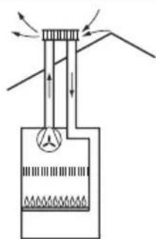
Type of air suction/fl ue gas exhaust ducting
| Combustion air drawn from the room |
| B22 Air drawn from the room |
 |
| B32 Individual or shared fl ue gas exhaust ducting built into the buildingAir drawn from the room |
 |
| Combustion air intake from outside |
| C12 Flue gas exhaust and air suction duct through external wall in the same range of pressure |
 |
| C22 Individual or shared fl ue gas exhaust and air suction through fl ue ducting built into the building |
 |


Electrical connections

WARNING
Before performing any work on the boiler, first disconnect it from the electrical power supply using the external bipolar switch.
230 V power supply + earth connection
The connection must be carried out using the 2P + E cable supplied with the boiler and connected to the main PCB.
Room thermostat connection
The room thermostat connection is carried out inside the box located under the control panel. Proceed as follows:
- Disconnect the electrical connections to the boiler.
- Rotate the control panel (see paragraph "Instructions for opening the casing and performing internal inspection").
- Open the box using a screwdriver.

- Connect the room thermostat cables by removing jumper S.

- Close the fl ap, control panel and front casing.
For further information, please consult the Chaff oteaux Manual.
Connection to a solar heating system
The boiler is equipped with a solar sensor for a series connection to a solar heating system for the production of domestic hot water (see instructions sheet).
To ensure that the integrated system operates correctly, the inlet temperature to the boiler must be limited by a mixing device.
Dip-switch (see electrical diagram)

- Start-up delay
ON = 2 minutes - default setting
OFF = 0 minutes - Post-ventilation after domestic hot water intake
ON = 5 seconds - default setting
OFF = 3 minutes - DO NOT MODIFY
- DO NOT MODIFY

Initial procedures
To guarantee safety and the correct operation of the appliance, the boiler must be prepared for operation by a qualified technician who possesses the skills which are required by law.
Electricity supply
- Check that the voltage and frequency of the electricity supply correspond to the data shown on the boiler data plate;
- Make sure that the earthing connection is efficient.
Filling the hydraulic circuit
Proceed as follows:
- open the relief valves on the radiators in the system;
- loosen the automatic air relief valve cap on the circulation pump;
- gradually open the water inlet valve and shut off the radiator relief valves as soon as water starts to come out;
- close the boiler inlet valve when the pressure gauge reading reaches 1 bar.
Control Panel

Gas supply
Proceed in the following manner:
- make sure that the main gas supply uses the same type of gas as indicated on the boiler data plate;
- Open all doors and windows;
- Make sure there are no sparks or naked flames in the room;
- Make sure that the system does not leak fuel using a cut-off valve inside the boiler itself which should be closed and then opened while the gas valve is disabled. The meter must not show any signs of gas being used for 10 minutes.
Legend:
- Central Heating temperature L.E.D (yellow) and error code signals
- On/Off L.E.D. (green)
- ON/OFF button
- Central Heating selection (winter) and temperature adjustment knob
- Domestic Hot Water temperature adjustment knob
- RESET button
- L.E.D. signaling anomalies:
Yellow - Defective discharge of exhaust fumes Red - signaling operating shutdown - Yellow LED, burner ON
First ignition
- Make sure that:
- The gas valve is closed; - The electrical connection has been properly carried out. Make sure that, in any case, the green/yellow earthing wire is connected to an efficient earthing system;
- Use a screwdriver to lift the cap on the automatic air relief valve;
- the system pressure reading is greater than 1 bar on the pressure gauge;
- Press the on/off button; the green ⒺLED 2 will light up. Turn the heating knob 4 between the min. and max. positions. The boiler pump will start up and attempt to ignite the burner. After 7 seconds the electronics will shut off the appliance as the

gas supply has been interrupted; the LED 8 - red ✕ - will light up.
- let the pump run until all the air has escaped from the system;
- bleed the air from the radiators;
- check the system pressure and, if it has decreased, fi ll the system with water until a pressure of 1 bar is restored.
-
The exhaust duct for combustion products should be suitable and free from any obstructions;
-
Any necessary ventilation inlets in the room should be open (type B installation).
-
Open the gas valve and check the connection seals, including the boiler connection seals, making sure that the meter does not detect any passage of gas. Eliminate any leaks.
-
Reset the boiler by pressing the Reset button 7.
The burner ignites: if this does not happen at the first attempt, repeat the procedure until ignition occurs.
Combustion Analysis
The fl ue connector has two apertures, readings can be taken for the temperature of the combustion by-products and of the combustion air, as well as of the concentrations of O2 and CO2, etc.
To access these intakes it is necessary to unscrew the front screw and remove the metal plate with sealing gasket.
The optimal test conditions at maximum heating power are achieved when the chimney sweep function is enabled (press the Reset button for 5 seconds; the green LED 2 will begin to flash). The boiler will automatically revert to normal operating conditions after 10 minutes, or if you switch the boiler OFF and ON again. When you have finished, reposition the metal plate correctly and make sure the seal fi ts perfectly.
Product of Combustion
Discharge Monitoring
In the boiler, it is possible to monitor the correct operation of the flue exhaust/air intake, checking for a loss of general pressure in the system. Through the use of a differential manometer connected to the test points of the combustion chamber, it is possible to detect the ΔP of operation of the air pressure switch.
The value detected should not be less than 0.47 mbar (24 kW) under conditions of maximum thermal power in order for the boiler to function properly and without interruption.

CHECKING THE GAS SETTINGS
Supply pressure check
- Loosen screw "1" (Fig. a) and insert the pressure gauge connection pipe into the pipe tap.
- Switch the boiler on at maximum power, enabling the "chimney sweep" function (press and hold the Reset button for 5 seconds; the green LED 2 will begin to flash). The supply pressure should correspond to the value established in relation to the type of gas for which the boiler is designed.
- When the check is over, tighten screw "1" and make sure it is securely in place.
- The "fl ue sweep function" is automatically deactivated after 10 minutes or when the Reset button is pressed.
Checking the maximum power
- To check the maximum power level, loosen screw "2" (Fig. b) and insert the pressure gauge connection pipe into the pipe tap.
- Disconnect the air chamber compensation tube.
- Switch the boiler on at maximum power, enabling the "chimney sweep" function (press and hold the Reset button for 5 seconds; the green LED 2 will begin to flash).
The supply pressure should correspond to the value shown in the "Gas Settings" table, in relation to the type of gas for which the boiler is designed. If it does not correspond, remove the protective hood and tighten or loosen the adjustment screw "3" (fi g. c).
- When the check is over, tighten screw "2" and make sure it is securely in place.
- Replace the cover protecting the modulator.
- Reconnect the compensation tube.
- The "fl ue sweep function" is automatically deactivated after 10 minutes or when the Reset button is pressed.
Checking the minimum power
- To check the minimum power level, loosen screw "2" (Fig. b) and insert the pressure gauge connection pipe into the pipe tap.
- Disconnect the air chamber compensation tube.


- Switch the boiler on at maximum power, enabling the "chimney sweep" function (press and hold the RESET button for 5 seconds; the green LED 2 will begin to flash).
Disconnect a wire from the modulator (fi g. d); the supply pressure should correspond to the value shown in the "Gas Settings" table, in relation to the type of gas for which the boiler is designed. If it does not correspond, tighten or loosen the adjustment screw "4" (fi g. d).
-
When the check is over, tighten screw "2" and make sure it is securely in place.
-
Reconnect the modulator wire.
-
Reconnect the compensation tube.
-
The "fl ue sweep function" is automatically deactivated after 10 minutes or when the Reset button is pressed.
ATTENTION
At the end verify that there are no gas leaks.
Adjust the maximum heating power and slow ignition power
-
To check/adjust the maximum heating and/or slow ignition power, loosen the screw ② (fig. b) and fit the pressure gauge connection hose into the pressure pipe tap.
-
Press and hold the on/off button for 10 seconds; when the LED 8 - red - begins to fl ash you may proceed with the necessary adjustments (fi g. e).
-
To adjust the maximum heating power, turn the heating knob 4 (fi g. e) as desired.
To adjust the maximum slow ignition power, turn the domestic hot water knob 5 (fi g. e) as desired.
-
This adjustment will automatically be stored in the memory of the appliance. If one of the two knobs is not adjusted, the boiler will retain the previously-set value in its memory. To exit the function, press and hold the on/off button for 10 seconds or wait for 1 minute.
-
When the check is complete, tighten the ② screw (fi g. b) and make sure it is securely in place.
Adjusting the heating ignition delay
Adjustment via the P.C.B.
The adjustment process is carried out via the P.C.B., using dip-switch no.1.
ON position = 2 minutes - default setting
OFF position = 0 minutes
If you adjust the position, it will be stored in the memory of the appliance immediately.
| Dip-switch 1 | confi guration |
| Ignition delay adjustment | ON = 2 min.OFF = 0 min. |

The table indicate the existing relationship between the gas pressure at the burner and the boiler power level in heating mode.
The boiler may be adjusted so that it may be used with Liquid Gas (G30-G31) instead of methane gas (G20) or vice-versa. The adjustment must be performed by a Qualified Technician using the special Kit.
The following procedures must be completed:
- Switch off the electrical supply to the appliance.
- Shut off the gas valve.
- Disconnect the electrical connections to the boiler.
-
Access to the combustion chamber, as indicated in the paragraph "Instructions for opening the casing and performing an internal inspection".
-
Replace the nozzles and attach the labels as indicated in the instruction sheet supplied with the Kit.
- Check that all connections are gas-tight.
- Start up the boiler.
- Perform the gas adjustment (refer to the paragraph "Checking the gas adjustment"):
- check the maximum power
- check the minimum power
- adjust the maximum adjustable heating power
- check / adjust the slow ignition
- adjust the heating ignition delay
- Carry out the combustion analysis.
Appliance shut-off conditions
The boiler is protected from malfunctions by means of internal checks performed by the electronic P.C.B., which stops the boiler from operating if necessary. In the event of the boiler being shut off in this manner, a code appears on the control panel display which refers to the type of shut-off and the reason behind it. Two types of shut-off may occur:
Safety shut-off
This type of error is "volatile", which means that the boiler starts up again automatically as soon as the problem which caused the shut-off is removed. (the led 8 - yellow - flash and the C.H. Temperature led "1" indicate the error code). In fact, soon as the cause of the shut-off disappears, the boiler starts up again and continues to operate normally.
If the boiler still indicates a safety shut-off, switch it off. Make sure the external electric switch is in the OFF position, shut off the gas valve and contact a qualified technician.
Shutdown due to insufficient water circulation
If the L.E.D. 8 - yellow - flash and the boiler is off, one possible cause for this state is an insufficient pressure of water in the system - see the code error table.
Check the water pressure on the pressure gauge 6 and make sure that is between 0.6 and 1.5 bar when the system is cold. If the pressure is just under the minimum refi ll the system by open the valve under the boiler.
If the pressure drops very frequently, there may be a water leak at some point in the system. If this is the case a plumber should be contacted.
Operation shutdown
This type of error is "non-volatile", which means that it is not removed automatically (the led 8 - red - will illuminate and the C.H. Temperature led "1" will indicate the error code). In this case the boiler does not restart automatically, but it may be reset by pressing the Reset button. If the problem manifests itself again after several attempts to reset the appliance, contact a qualified technician.
Important
If this shutdown occurs frequently, contact an authorised service centre for assistance. For safety reasons, the boiler will allow a maximum of 5 reset operations to take place in 15 minutes (individual presses of the Reset button).
If the shutdown is occasional or an isolated event, this is not a problem.
Anti-frost Device
The anti-frost function acts on the central heating flow temperature probe, independently from other regulations, when the electrical supply is turned on.
If the primary circuit temperature falls below 8° C the pump will run for 2 minutes.
After the two minutes of circulation (fi xed) the boiler will check the following:
a) if the central heating flow temperature is > 8°C, the pump stops;
b) if the central heating flow temperature is between 4 and 8°C, the pump will run for another two minutes;
c) if the central heating flow temperature is < 4°C, the burner will fire (heating position) at minimum power until the temperature reaches 33°C, the burner will go out and the pump will continue to run for two minutes.
If the flow temperature remains between 4-8°C the pump will continue to run for two minutes for a maximum of 10 times unless a temperature above 8°C is detected in the central heating flow, after this the the burner will fire. If lockout is caused by overheat the burner is kept OFF.
The anti-frost device activates only when (with the boiler operating correctly):
- the system pressure is correct;
- the boiler is electrically powered;
- there is a supply of gas.
Code error table
| C.H. water temperature green led - 1 - | Led 8 Reset 7  | Description Note: ○ = linking ● = fixed | |||||||
| 40 | 50 | 60 | 70 | 80 | 90 | yellow | red | ||
| ● | ● | X Overheating | |||||||
| ○ | ○ | ○ | |||||||
| ○ | ○ | ● | X Insuffi cient water circulation advice | ||||||
| ○ | ○ | ● | |||||||
| ○ | ○ | ○ | |||||||
| ○ | ○ | ○ | |||||||
| ○ | ○ | ||||||||
| ○ | ○ | ||||||||
| ○ | ● | X Comunication error Main PCB-Control panel PCB | |||||||
| ○ | ● | X Problema alla scheda elettronica / Main P.C.B. error | |||||||
| ○ | ○ | ○ | ○ | ○ | ○ | ○ | |||
| ● | X Too many (>5) resets in 15 minutes | ||||||||
| ○ | ○ | ○ | ○ | ||||||
| ○ | ○ | ○ | ○ | ||||||
| ● | |||||||||
Maintenance is an essential part of the safe and efficient operation of the boiler and ensures its durability. It should be performed according to the instructions given in current legislation. Perform combustion analysis regularly in order to check the operating efficiency of the boiler and to make sure any polluting substances relaxed are within the boundaries set by current legislation.
Before beginning maintenance work:
- Disconnect the appliance from the electricity supply by turning the external bipolar switch to the "OFF" position;
- Close the gas valve and the central heating and domestic hot water system valve.
After the work has been completed the initial settings will be restored.
General comments
It is recommended that the following inspections be carried out on the boiler at least once a year:
- Check the seals in the water part and, if necessary, replace the gaskets and restore the seal to perfect working order.
- Check the seals in the gas part and, if necessary, replace the gaskets and restore the seal to perfect working order.
- Visually check the overall condition of the boiler.
- Visually check the combustion and, if necessary, disassemble and clean the burner.
- Following the inspection detailed in point "3", disassemble and clean the combustion chamber, if necessary.
- Following the inspection detailed in point "4", disassemble and clean the burner and injector, if necessary.
- Cleaning the primary heat exchanger
- Make sure the following heating safety devices are operating correctly:
- temperature limit safety device.
- Make sure that the following gas part safety devices are operating correctly:
- absence of gas or flame safety device (ionisation).
- Check the efficiency of the domestic hot water production process (test the flow rate and temperature).
- Perform a general inspection of the boiler operation.
- Remove oxide from the detection electrode using an emery cloth.


Operational test
After having carried out the maintenance operations, fi ll the heating circuit at a pressure of approximately 1.0 bar and release the air from the system.
Fill the domestic hot water system at the same time.
- Begin operating the boiler.
- If necessary, release the air from the heating system again.
- Check the settings and make sure all the command, adjustment and monitoring parts are working correctly.
- Check the seal and that the system for the expulsion of fumes/suction of comburent air is operating correctly.
Draining procedures
The heating system must be drained using the following procedure:
- Switch off the boiler, make sure the external bipolar switch is in the OFF position and shut off the gas valve;
- Loosen the automatic air relief valve;
- Open the system discharge valve and collect the escaping water in a container;
- Empty the water from the lowest points of the system (where applicable).

If the system is to be left inactive in areas where the room temperature may fall below 0° C during winter, we recommend that anti-freeze liquid is added to the water in the heating system in order to avoid the need for repeated draining; when this liquid is used make sure it is compatible with the stainless steel used for the bodywork of the boiler.
We recommend the use of anti-freeze products which contain PROPYLENE GLYCOLS as these inhibit corrosion and that they are used in conjunction with the anti-scaling and anti-corrosion function, in the quantities suggested by the manufacturer, at the minimum temperature.
Regularly check the pH level of the water/anti-freeze mix in the boiler circuit and replace it when the value measured is lower than the limit prescribed by the manufacturer.
DO NOT MIX DIFFERENT TYPES OF ANTI-FREEZE.
The manufacturer will not be held liable for any damage caused by the appliance or the system due to the use of inappropriate anti-freeze substances or additives.
Draining the domestic hot water system
Every time there is a danger of freezing, the domestic hot water system must be drained as follows:
- Shut off the water mains inlet valve;
- Open all the hot and cold water taps;
- Empty the water from the lowest points of the system (where applicable).
WARNING
Before handling, empty all components which may contain hot water, performing bleeding where necessary.
Descale the components in accordance with the instructions provided on the safety data leaf et supplied with the product used, make sure the room is well ventilated, wear protective clothing, avoid mixing different products, and protect the appliance and surrounding objects.
Seal all openings used to take a gas pressure reading or to make any gas adjustments.
Make sure that the nozzle is compatible with the supplied gas.
If a smell of burning is detected or smoke is seen leaking from the appliance, or there is a smell of gas, disconnect it from the electricity supply, shut off the gas valve, open the windows and call for technical assistance.
Information for the user
Inform the user on how to operate the appliance.
In particular, provide the user with the instruction manuals and inform him/her that these must be stored with the appliance.
Moreover, make sure the user is aware of the following:
- The system water pressure must be checked regularly (instruct the user on how to fi ll and bleed the system).
- How to set the temperature and adjustment devices for using the appliance correctly and in a more cost-efficient way.
- The system must be serviced regularly in compliance with legislation.
- The settings relating to the supply of combustion air and combustion gas must not in any event be modified.
| GEN. NOTES | Model Name | ALIXIA 24 FF | |
| CE certifi cation (pin) | 1312BR4793 | ||
| Boiler type | C12-C22 -C32-C42-C52-C82 B22-B22p-B32 | ||
| ELECTRICAL PERFORMANCE | Max/min nominal heat input(Hi) | kW | 25,8 / 11,0 |
| Max/min nominal heat input (Hs) | kW | 28,7 / 12,2 | |
| Heat output: max/min kW 24,2 / 9,8 | |||
| Combustion effi ciency (at fl ue) Hi/Hs | % | 94,5 | |
| Gross effi ciency of nominal heat input (60/80 °C) Hi/Hs | % | 93,8 / 84,5 | |
| Gross effi ciency at 30 % at 47°C Hi/Hs | % | 93,6 / 84,3 | |
| Gross effi ciency at minimum power Hi/Hs | % | 89,2 / 80,3 | |
| Number of effi ciency stars (Directive 92/42/EEC) | stars | *** | |
| Rating Sedbuk | class | D | |
| Heat loss through the fl ue when burner off | % | 0,4 | |
| Heat loss through the fl ue when burner on | % | 5,5 | |
| EMISSIONS | Residual discharge head | Pa | 100 |
| Nox class | class | 3 | |
| Flue fumes temperature (G20) | °C | 105 | |
| CO2 content2 (G20) | % | 6,5 | |
| CO content (0 %O2) | ppm | 50 | |
| O2 content2 (G20) | % | 8,8 | |
| Max capacity fumes (G20) | Kg/h | 56,8 | |
| Excess air | % | 72 | |
| HEATING CIRCUIT | Load losses water side (max) ΔT=20°C | mbar | 200 |
| Expansion vessel pre-charged pressure | bar | 1 | |
| Maximum central heating circuit pressure | bar | 3 | |
| Expansion vessel capacity | l | 8 | |
| Central heating temperature: max/min(high temperature range) | °C | 85 / 35 | |
| DOMESTIC HOT WATER CIRCUIT | Domestic hot water temperature max/min | °C | 60 / 36 |
| Specifi c flow rate of domestic hot water system (10 min. with ΔT=30°C) instant boilers | l/min | 11,3 | |
| D.H.W. flow rate ΔT=25°C | l/min | 13,6 | |
| D.H.W. flow rate ΔT=35°C | l/min | 9,7 | |
| Hot water comfort stars (EN13203) | stars | ** | |
| D.H.W. minimum flow rate | l/min | 1,7 | |
| Domestic hot water pressure max/min | bar | 7 | |
| ROOMELECTRICAL DATA | Power supply voltage/frequency | V/Hz | 230/50 |
| Power consumption | W | 106 | |
| Minimum operating room temperature | °C | +5 | |
| Electric system grades of protection | IP | X5D | |
| Weight | kg | 30 | |
| Dimensions (W x H x D) : | mm | 400/780/315 |
Ariston Thermo SpA
- WARNINGS
- PRODUCT DESCRIPTION
- INSTALLATION
- COMMISSIONING
- SETTINGS
- BOILER PROTECTION DEVICES....51
- MAINTENANCE
- TECHNICAL INFORMATION
- SAFETY REGULATIONS
- ADVICE FOR THE INSTALLER
- BEFORE INSTALLING THE APPLIANCE
- RECOMMENDATIONS
- WARNING
- PLANNING AND CARRYING OUT INSTALLATION
- DOMESTIC HOT WATER CIRCUIT
- MAIN HEATING CIRCUIT
- ANTI-CORROSION MEASURES
- CLEANING THE HEATING SYSTEM
- CE LABELLING
- LEGEND
- CONNECTING THE FLUE
- TYPES OF BOILER - FL UE EXHAUST CONNECTION
- ELECTRICAL CONNECTIONS
- IMPORTANT
- MINIMUM CLEARANCES
- WATER/GAS SUPPLY CONNECTION
- MOUNTING THE HYDRAULIC BAR KIT (OPTIONAL)
- INSTRUCTIONS FOR OPENING THE CASING AND PERFORMING INTERNAL INSPECTION
- BOILER INSTALLATION
- EXCESSIVE PRESSURE DEVICE
- FLUE GAS EXHAUST / AIR SUCTION DUCT CONNECTION
- TYPE OF AIR SUCTION/FL UE GAS EXHAUST DUCTING
- ROOM THERMOSTAT CONNECTION
- CONNECTION TO A SOLAR HEATING SYSTEM
- DIP-SWITCH (SEE ELECTRICAL DIAGRAM)
- INITIAL PROCEDURES
- ELECTRICITY SUPPLY
- FILLING THE HYDRAULIC CIRCUIT
- GAS SUPPLY
- FIRST IGNITION
- COMBUSTION ANALYSIS
- PRODUCT OF COMBUSTION
- DISCHARGE MONITORING
- CHECKING THE GAS SETTINGS
- SUPPLY PRESSURE CHECK
- CHECKING THE MAXIMUM POWER
- CHECKING THE MINIMUM POWER
- ATTENTION
- AT THE END VERIFY THAT THERE ARE NO GAS LEAKS
- ADJUST THE MAXIMUM HEATING POWER AND SLOW IGNITION POWER
- ADJUSTING THE HEATING IGNITION DELAY
- APPLIANCE SHUT-OFF CONDITIONS
- SAFETY SHUT-OFF
- SHUTDOWN DUE TO INSUFFICIENT WATER CIRCULATION
- OPERATION SHUTDOWN
- ANTI-FROST DEVICE
- GENERAL COMMENTS
- OPERATIONAL TEST
- DRAINING PROCEDURES
- DO NOT MIX DIFFERENT TYPES OF ANTI-FREEZE
- DRAINING THE DOMESTIC HOT WATER SYSTEM
- INFORMATION FOR THE USER
- ARISTON THERMO SPA
Brand : CHAFFOTEAUX
Model : Alixia 24 FF
Category : Boiler