
CGIH3047VF - Electric stove FRIGIDAIRE - Free user manual and instructions
Find the device manual for free CGIH3047VF FRIGIDAIRE in PDF.
| Product Type | Electric Range |
| Brand | Frigidaire |
| Model | CGIH3047VF |
| Width | 76.2 cm (30") |
| Depth | 68.6 cm (27") approximately |
| Height (with cooktop) | 91.4 cm (36") typical |
| Power Supply | 240 V, 60 Hz, single-phase, 4-wire |
| Rated Power | See rating plate (kW) |
| Cooktop Type | Electric coil or ceramic glass depending on model |
| Number of Burners | 4 or 5 depending on configuration |
| Oven | Electric, standard capacity |
| Anti-Tip Bracket | Included, must be installed to wall or floor |
| Leveling Legs | 4 adjustable legs |
| Minimum Clearance Above | 76.2 cm (30") to unprotected cabinet |
| Side Clearance | 5" (12.7 cm) minimum above 36" height |
| Maintenance | Clean with non-abrasive products; refer to user guide |
| Types of Spare Parts | Surface elements, handles, brackets, etc. |
| Reparability | Intervention by a qualified installer recommended |
| Warranty | See use and care guide |
Frequently Asked Questions - CGIH3047VF FRIGIDAIRE
User questions about CGIH3047VF FRIGIDAIRE
0 question about this device. Answer the ones you know or ask your own.
Ask a new question about this device
Download the instructions for your Electric stove in PDF format for free! Find your manual CGIH3047VF - FRIGIDAIRE and take your electronic device back in hand. On this page are published all the documents necessary for the use of your device. CGIH3047VF by FRIGIDAIRE.
USER MANUAL CGIH3047VF FRIGIDAIRE
INSTALLATION INSTRUCTIONS
FRONT CONTROL FREESTANDING ELECTRIC RANGE
INSTALLATION AND SERVICE MUST BE
PERFORMED BY A QUALIFIED INSTALLER.
IMPORTANT: SAVE FOR LOCAL ELECTRICAL INSPECTOR'S USE.
READ AND SAVE THESE INSTRUCTIONS FOR FUTURE REFERENCE.
United States

! WARNING FOR YOUR SAFETY: Do not store or use gasoline or other flammable vapors and liquids in the vicinity of this or any other appliance.
IMPORTANT SAFETY INSTRUCTIONS
⚠ WARNING If the information in this manual is not followed exactly, a fire or electrical shock may result causing property damage, personal injury or death.
Important Notes to the Installer:
- Read all instructions contained in these installation instructions before installing range.
- Remove all packing material from the oven compartments before connecting the gas & electrical supply to the range.
- Observe all governing codes and ordinances.
- Be sure to leave these instructions with the consumer.
Important Notes to the Consumer:
Keep these instructions with your owner's guide for future reference.
- As when using any appliance generating heat, there are certain safety precautions you should follow. These are listed in the Use & Care Guide, read it carefully.
- Be sure your range is installed and grounded properly by a qualified installer or service technician.
- Make sure the wall coverings around the range can withstand the heat generated by the range.
- To eliminate the need to reach over the surface elements, cabinet storage space above the elements should be avoided.
WARNING
Tip Over Hazard

natural_image
Silhouette of a person pushing a large block with a magnifying glass (no text or symbols)- A child or adult can tip the range and be killed.
-
Verify the anti-tip device has been installed to floor or wall.
-
Ensure the anti-tip device is re-engaged to floor or wall when the range is moved.
- Do not operate the range without the anti-tip device in place and engaged.
- Failure to follow these instructions can result in death or serious burns to children and adults.

Range
leveling leg
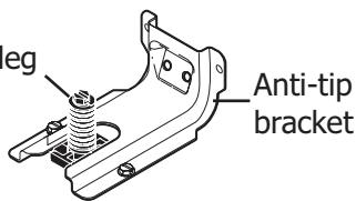
To check if the anti-tip bracket is installed properly, use both arms to grasp the rear edge of the range back. Carefully attempt to tilt range forward. When properly installed, the range should not tilt forward.
Refer to the anti-tip bracket installation instructions supplied with your range for proper installation.
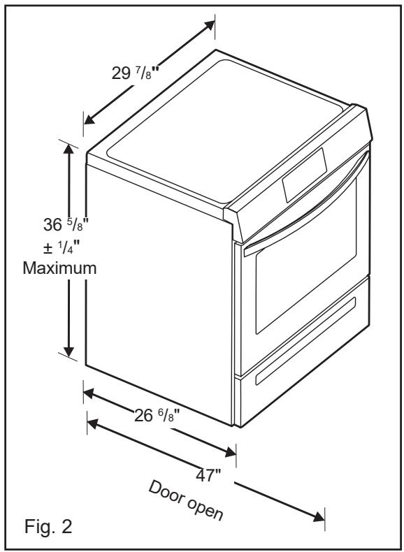
1. Clearances and Dimensions
a. Provide adequate clearances between the range and adjacent combustible surfaces.
b. Location—Check location where the range will be installed. Check for proper electrical supply and the stability of floor.
c. Dimensions that are shown must be used. Given dimensions provide minimum clearance. Contact surface must be solid and level.
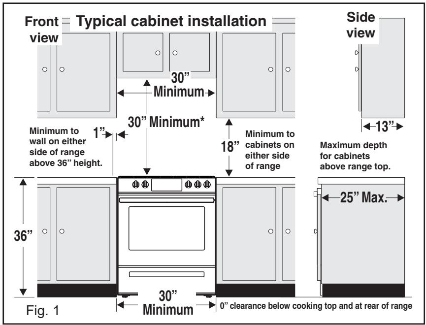
*30" (762 mm) MINIMUM CLEARANCE BETWEEN THE TOP OF THE COOKING SURFACE AND THE BOTTOM OF AN UNPROTECTED WOOD OR METAL CABINET; OR 24" (610 mm) MINIMUM WHEN BOTTOM OF WOOD OR METAL CABINET IS PROTECTED BY NOT LESS THAN 1/4" (6 mm) FLAME RETARDANT MILLBOARD COVERED WITH NOT LESS THAN NO. 28 MSG SHEET STEEL, 0.015" (0.4 mm) STAINLESS STEEL, 0.024" (0.6 mm) ALUMINUM OR 0.020" (0.5 mm) COPPER. 0" (0 mm) CLEARANCE IS THE MINIMUM FOR THE REAR OF THE RANGE. FOLLOW ALL DIMENSION REQUIREMENTS PROVIDED ABOVE TO PREVENT PROPERTY DAMAGE, POTENTIAL FIRE HAZARD, AND INCORRECT COUNTERTOP AND CABINET CUTS.
TO ELIMINATE THE RISK OF BURNS OR FIRE BY REACHING OVER HEATED SURFACE UNITS, CABINET STORAGE SPACE LOCATED ABOVE THE SURFACE UNITS SHOULD BE AVOIDED. IF CABINET STORAGE IS TO BE PROVIDED, THE RISK CAN BE REDUCED BY INSTALLING A RANGE HOOD THAT PROJECTS HORIZONTALLY A MINIMUM OF 5" (127 mm) BEYOND THE BOTTOM OF THE CABINETS.
2. Tools You Will Need
For leveling legs and Anti-Tip Bracket:
- Adjustable wrench or channel lock pliers
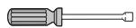
- 5/16" Nutdriver or Flat Head Screwdriver
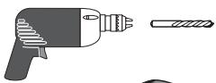
- Electric Drill & 1/8" Diameter Drill Bit (Masonry Drill Bit if installing in concrete)
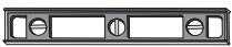
• Level & Measuring Tape
For electrical supply connection:
- 1/4" & 3/8" Socket driver or Nutdriver Additional Materials You Will Need:
• Power Supply Cord or
• Copper Electrical Wiring & Metal Conduit (for hard wiring)


3. Anti-Tip Bracket Installation Instructions
Important Safety Warning
To reduce the risk of tipping of the range, the range should be secured to the floor by properly installed anti-tip bracket and screws packed with the range. Failure to install the anti-tip bracket will allow the range to tip over if excessive weight is placed on an open door or if a child climbs upon it. Serious injury might result from spilled hot liquids or from the range itself.
If range is ever moved to a different location, the anti-tip brackets must also be moved and installed with the range.
Instructions are provided for installation in wood or cement fastened to either the floor or wall. When installed to the wall, make sure that screws completely penetrate dry wall and are secured in wood or metal. When fastening to the floor or wall, be sure that screws do not penetrate electrical wiring or plumbing.
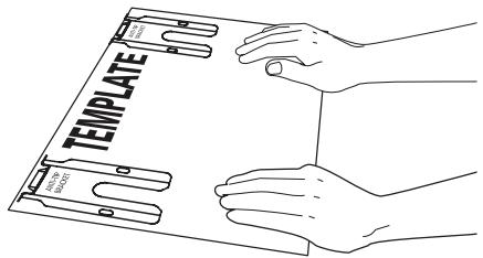
A. Locate the Bracket Using the Template - (Bracket may be located on either the left or right side of the range. Use the information below to locate the bracket if template is not available). Mark the floor or wall where left or right side of the range will be located. If rear of range is against the wall or no further than 1-1/4" (32 mm) from wall when installed, you may use the wall or floor mount method. If molding is installed and does not allow the bracket to fit flush against the wall, remove molding or mount bracket to the floor. For wall mount, locate the bracket by placing the back edge of the template against the rear wall and the side edge of template on the mark made referencing the side of the range. Place bracket on top of template and mark location of the screw holes in wall. If rear of range is further than 1-1/4" (32 mm) from the wall when
installed, attach bracket to the floor. For floor mount, locate the bracket by placing back edge of the template where the rear of the range will be located. Mark the location of the screw holes, shown in template.
B. Drill Pilot Holes and Fasten Bracket - Drill a 1/8" (3 mm) pilot hole where screws are to be located. If bracket is to be mounted to the wall, drill pilot hole at an approximate 20° downward angle. If bracket is to be mounted to masonry or ceramic floors, drill a 5/32" (4 mm) pilot hole 1-3/4" (44 mm) deep. The screws provided may be used in wood or concrete material. Use a 5/16" (8 mm) nut-driver or flat head screwdriver to secure the bracket in place.
FASTEN BRACKET (FLOOR MOUNTING ONLY)
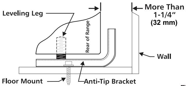
Fig. 4
FASTEN BRACKET (WALL OR FLOOR MOUNTING)
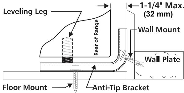
Fig. 5
30" ELECTRIC FRONT CONTROL FREESTANDING INSTALLATION INSTRUCTIONS
C. Level and Position Range - Level range by adjusting the (4) leveling legs with a wrench. Note: A minimum clearance of 1/8" (3 mm) is required between the bottom of the range and the leveling leg to allow room for the bracket. Use a spirit level to check your adjustments. Slide range back into position. Visually check that rear leveling leg is inserted into and fully secured by the Anti-Tip Bracket by removing lower panel or storage drawer. For models with a warmer drawer or broiler compartment, grasp the top rear edge of the range and carefully attempt to tilt it forward.
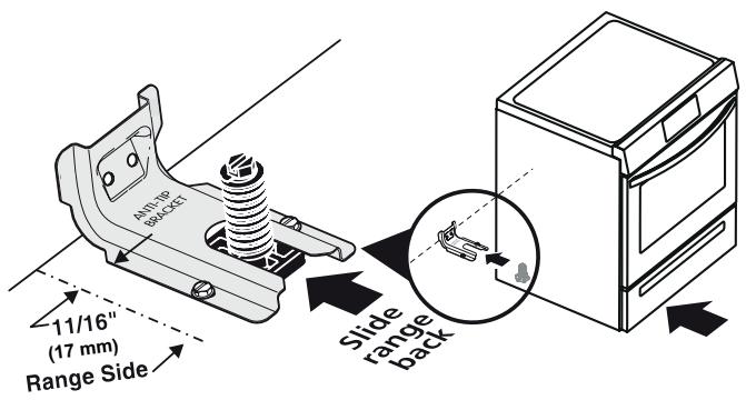
Fig. 6
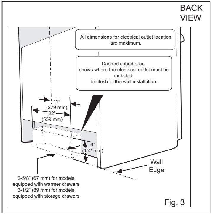
4. Electrical Connection Requirements
WARNING Avoid fire hazard or electrical shock. Failure to follow this warning may cause serious injury, fire, or death.
Plug the range power cable (4 conductors) into a 4 conductor range outlet. Outlet must be properly grounded and in accordance with the Canadian Electrical Code (CSA Standard (C22.1 Part 1 -- latest edition) -- and any local electrical code requirements.
Locate outlet 6" (152 mm) above the floor in the wall behind the range.
Grounding Instructions
For personal safety, this appliance must be properly grounded. For maximum safety, the power cord must be plugged into an electrical outlet that is correct voltage, is correctly polarized and properly grounded in accordance with local codes.
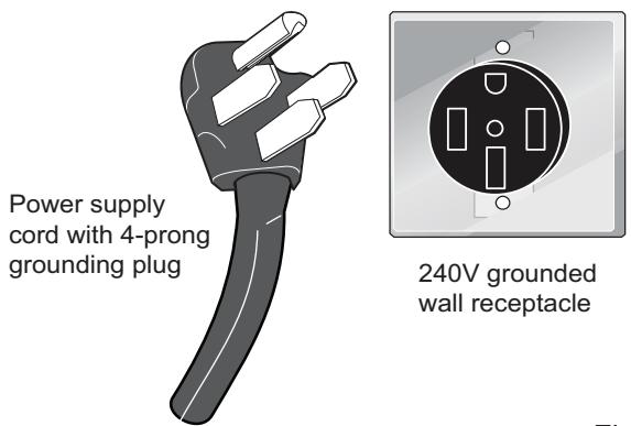
Fig. 7
It is the personal responsibility of the consumer to have the appropriate outlet with the correct, properly grounded wall receptacle installed by a qualified electrician.
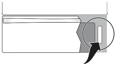
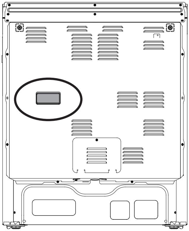
5. Model and Serial Number Location
The serial plate is located on the right-hand surface of the oven front frame at the storage or warmer drawer; or the lower panel area.
When ordering parts for or making inquires about your range, always be sure to include the model and serial numbers and a lot number or letter from the serial plate on your range.
Your serial plate also tells you the Kilowatt rating (power requirements) and Voltage ratings.
Serial Plate Locations:
natural_image
Pure technical diagram showing a mechanical component with a magnified inset (no text or symbols)Serial plate is located on the lower right front frame of the appliance. Alternate location may be under cooktop. Fig.
Fig. 8
6. Install filler trim kit
Note: Installation of the filler trim kit is not required.
WARNING Disconnect electrical power to range before beginning installation. Before servicing any part of the appliance, make sure the appliance is off and the surfaces are cool. Attempting to service the appliance while hot may cause burns or other injury.
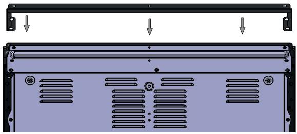
Filler Trim Attachment Instructions:
- Remove the 7 screws on the vent trim on the back.
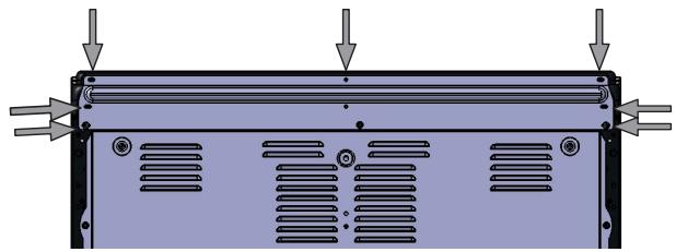
natural_image
Diagram of a device rear panel with ventilation slots and directional arrows indicating flow or movement (no text or symbols)Fig. 9
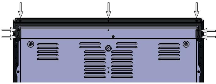
- Place the filler trim over the back by lining up the 7 screw holes of the filler trim with the vent trim and tighten screws.
natural_image
Diagram of a computer monitor rear panel with ventilation slots and mounting brackets (no text or symbols)Fig. 10
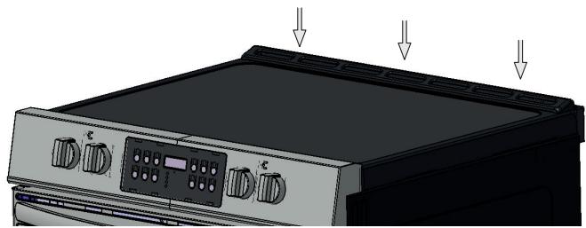
- When filler trim is secured it will be flush with the top of the range.
natural_image
Diagram of a computer chassis with ventilation slots and mounting brackets (no text or symbols)Fig. 11
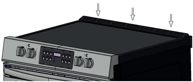
natural_image
Illustration of a kitchen appliance with control panel and three arrows pointing to top (no text or symbols)Fig. 12 - Range with filler trim installed.
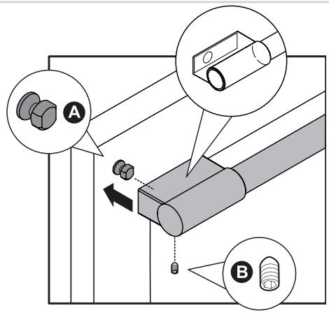
7. Door Handle Mounting Instructions (some models)
- Remove handles from carton and any other protective packaging.
- Position handle end caps over left and right pre-installed shoulder bolts (A) that are fastened to the door, ensuring the holes for the set screws are facing down.
- While holding handle firmly against door, loosely tighten right Allen set screw (B) with supplied Allen wrench until there is no gap between handle and door.
- Still holding the handle firmly to the door, firmly tighten left Allen set screw (B) with supplied Allen wrench.
- Return to the right Allen set screw (B) and firmly tighten with supplied Allen wrench.

NOTE
All set screws should be tightened so the screw is below the surface of the handle. The handle should be drawn tight to the door with no gaps.
The door handle may loosen over time or if it was installed improperly. If this happens, tighten the set screws on the handles.

8. Care, Cleaning and Maintenance
Refer to the Use & Care Manual for cleaning instructions.
If removing the range is necessary for cleaning or maintenance, disconnect the electrical power supply. If the electrical supply is inaccessible, lift the unit slightly at the front and pull out away from the wall. Pull only as far as necessary to disconnect the electrical supply. Finish removing the unit for servicing and cleaning. Reinstall in reverse order making sure to level the range and check electrical connections. See pages 2 and 3 for proper anchoring instructions.
WARNING Some models have a cool-air intake vent on the rear of the appliance. Do not block or obstruct this vent.
natural_image
Technical line drawing of a computer chassis back panel with ventilation slots and a highlighted oval component (no text or symbols)Fig. 13
Before You Call for Service
Read the "Before You Call" and operating instruction sections in your Use & Care Manual. It may save you time and expense. The list includes common occurrences that are not the result of defective workmanship or materials in this appliance.
Refer to the warranty in your Use & Care Manual for our toll-free service number and address. Please call or write if you have inquiries about your range product and/or need to order parts.
INSTALLATION INSTRUCTIONS
natural_image
Silhouette of a person pushing a large object with a magnifying glass (no text or symbols)! AVERTISSEMENT
natural_image
Illustration of three different types of office appliances: a drill, a measuring tool, and a handheld device (no text or symbols present)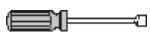
natural_image
Simple line drawing of a rectangular object with a magnified circular detail (no text or symbols)natural_image
Diagram of a server rack with ventilation slots and mounting points (no text or symbols)Fig. 9
natural_image
Diagram of a computer monitor rear panel with ventilation slots and mounting brackets (no text or symbols)Fig. 10
natural_image
Diagram of a computer chassis back panel with ventilation slots and mounting holes (no text or symbols)Fig. 11
natural_image
Illustration of a kitchen appliance with control panel and ventilation slots (no text or symbols)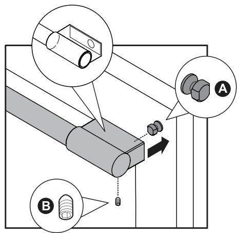
natural_image
Front view diagram of a computer chassis with ventilation slots and a highlighted rectangular component (no text or symbols)Fig. 13
- INSTALLATION INSTRUCTIONS
- FRONT CONTROL FREESTANDING ELECTRIC RANGE
- INSTALLATION AND SERVICE MUST BE
- PERFORMED BY A QUALIFIED INSTALLER.
- IMPORTANT SAFETY INSTRUCTIONS
- WARNING
- Tip Over Hazard
- Clearances and Dimensions
- Tools You Will Need
- Anti-Tip Bracket Installation Instructions
- 30" ELECTRIC FRONT CONTROL FREESTANDING INSTALLATION INSTRUCTIONS
- Electrical Connection Requirements
- Model and Serial Number Location
- Install filler trim kit
- Filler Trim Attachment Instructions:
- Door Handle Mounting Instructions (some models)
- NOTE
- Care, Cleaning and Maintenance
- Before You Call for Service
- ! AVERTISSEMENT
Brand : FRIGIDAIRE
Model : CGIH3047VF
Category : Electric stove