CBNEF5715 - Combined refrigerator LIEBHERR - Free user manual and instructions
Find the device manual for free CBNEF5715 LIEBHERR in PDF.

| Product type | Combined refrigerator |
| Brand | Liebherr |
| Model | CBNEF5715 |
| Climate class | SN, N, ST, T (from 10°C to 43°C depending on class) |
| Dimensions (H × W × D) | 1850 × 700 × 665 mm (680 mm with spacers) |
| Supply voltage | 220-240 V ~ |
| Frequency | 50 Hz |
| Refrigerant | R600a (flammable, eco-friendly) |
| Weight (estimated) | About 90 kg |
| Main functions | NoFrost, SuperCool, SuperFrost, IceMaker*, BioCool, VarioSpace, SabbathMode, child lock, fan |
| Interior lighting | LED, energy class G |
| Installation type | Freestanding (not built-in) |
| Connectivity | SmartDevice Box (optional, WiFi) |
| Air filter | FreshAir Filter, replacement every 12 months |
| Refrigerator temperature | 1°C to 9°C (recommended 5°C) |
| Freezer temperature | -26°C to -16°C (recommended -18°C) |
| Freezing capacity | Up to 24 kg/24h (according to rating plate) |
| Maintenance | Automatic NoFrost defrosting, yearly ventilation grille cleaning |
| Spare parts | FreshAir filter, LED bulb, door seals, drawers, shelves |
| Safety | Door alarm, temperature alarm, child lock, automatic shutdown in case of fault |
Frequently Asked Questions - CBNEF5715 LIEBHERR
User questions about CBNEF5715 LIEBHERR
0 question about this device. Answer the ones you know or ask your own.
Ask a new question about this device
Download the instructions for your Combined refrigerator in PDF format for free! Find your manual CBNEF5715 - LIEBHERR and take your electronic device back in hand. On this page are published all the documents necessary for the use of your device. CBNEF5715 by LIEBHERR.
USER MANUAL CBNEF5715 LIEBHERR
natural_image
Technical line drawing of a refrigerator interior showing storage compartments and doors (no text or labels)20220725
7088159 - 00
CN(ef/bs/fr/i)
Contents
1 Appliance at a glance.... 2
1.1 Overview of the appliance and its equipment...... 2
1.2 Appliance range of use.... 3
1.3 Conformity.... 3
1.4 EPREL database* 3
1.5 Installation dimensions.... 3
1.6 Saving energy.... 3
1.7 Example of contents arrangement.... 4
1.8 Smart device 4
2 General safety information.... 4
3 Controls and displays.... 6
3.1 Home screen.... 6
3.2 Operating structure.... 6
3.3 Navigation.... 6
3.4 Display symbols.... 7
3.5 Appliance options.... 7
4 Putting into operation.... 7
4.1 Transporting the appliance.... 7
4.2 Installing the appliance.... 7
4.3 Reversing the door.... 8
4.4 Sliding into the row of units.... 14
4.5 Disposing of packaging.... 14
4.6 Connecting the appliance.... 15
4.7 Switching on the appliance.... 15
4.8 SmartDevice box.... 15
4.9 Inserting the FreshAir filter. 16
4.10 Setting the clean ventilation grid timer.... 16
5 Control.... 17
5.1 Changing the temperature unit.... 17
5.2 Child proofing.... 17
5.3 SabbathMode.... 17
5.4 Refrigerator compartment.... 17
5.5 Freezer compartment.... 20
6 Maintenance.... 23
6.1 Change the FreshAir filter.... 23
6.2 Defrosting with NoFrost.... 23
6.3 Cleaning the ventilation grid.... 23
6.4 Cleaning the appliance.... 24
6.5 Cleaning the IceMaker* 24
6.6 Customer service.... 25
6.7 Energy efficiency class lighting* 25
7 Malfunctions.... 25
8 Messages.... 27
9 Decommissioning.... 28
9.1 Switching the appliance off.... 28
9.2 Taking the appliance out of service.... 28
10 Disposal.... 28
10.1 Preparing appliance for disposal.... 28
10.2 Disposing of the appliance in an environmentally friendly manner.... 28
The manufacturer works constantly on the further development of all the types and models. Therefore please understand that we have to reserve the right to make design, equipment and technical modifications.
To get to know all the benefits of your new appliance, please read the information contained in these instructions carefully.
The instructions apply to several models. Differences may occur. Text relating only to specific appliances is marked with an asterisk (*).
Instructions are marked with a ▶, and results are marked with a ▷.
1 Appliance at a glance
1.1 Overview of the appliance and its equipment
Exemplary illustration of the appliance model
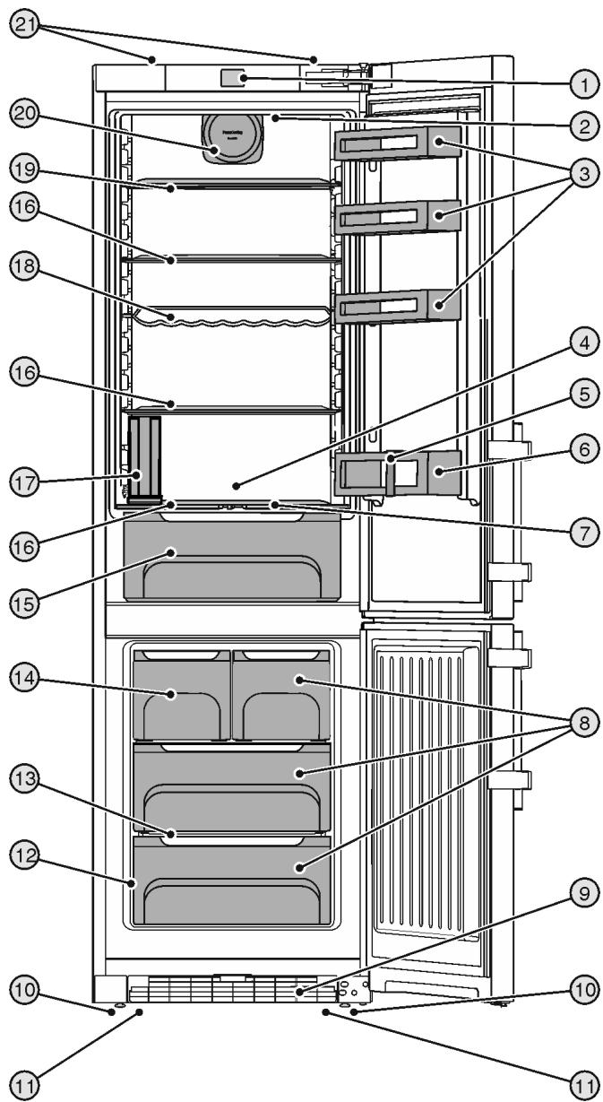
Fig. 1
(1) Operating and control elements
(2) Internal LED light
(3) Can rack
(4) Coldest zone
(5) Bottle holder
(6) Bottle shelf
(7) Humidity adjustment plate
(8) Freezer compartment
(9) Ventilation grid
(10) Adjusting feet
(11) Front transport handles, rear transport castors
(12) Model plate
(13) Variospace
(14) IceMaker*
(15) BioCool box, controllable
(16) Shelf
(17) Water tank*
(18) Bottle shelf
(19) Shelf, can be split
(20) Fan, with holder for fresh air filter
(21) Rear transport handles
Note
▶ Shelves, drawers and baskets are arranged for optimum energy efficiency when the appliance is delivered. Changing how the shelves, for example, are inserted in the fridge compartment does not have any impact on energy consumption.
1.2 Appliance range of use
Intended use
The appliance is only suitable for cooling food products in a domestic or household-like environment. This includes, for example, use:
- in staff kitchens, bed and breakfast establishments,
- by guests in country houses, hotels, motels and other accommodation,
- for catering and similar services in the wholesale trade.
The appliance is not suitable as a built-in unit.
All other types of use are not permitted.
Foreseeable misuse
The following applications are expressly forbidden:
- Storing and refrigerating medicines, blood plasma, laboratory preparations or similar substances and products based on the Medical Device Directive 2007/47/EC
- Use in areas at risk of explosions
Misusing the appliance may lead to damage to the goods stored or they may spoil.
Climate classifications
Depending on the climate classification the appliance is designed to operate in restricted ambient temperatures. The climate classification applying to your appliance is printed on the rating plate.
Note
▶ Keep to the specified ambient temperatures in order to guarantee that the appliance works properly.
| Climate classification | for ambient temperatures of |
| SN | 10 °C to 32 °C |
| N | 16 °C to 32 °C |
| ST | 16 °C to 38 °C |
| T | 16 °C to 43 °C |
1.3 Conformity
The refrigerant circuit has been tested for leaks. This device complies with the applicable safety regulations and with the directives 2014/35/EU, 2014/30/EU, 2009/125/EC, 2011/65/EU, 2010/30/EU and 2014/53/EU.
The full text of the EU Declaration of Conformity is available on the following website: www.Liebherr.com
1.4 EPREL database\*
Details about energy labelling and ecodesign requirements will be available on the European product database (EPREL) from 1st March 2021. You can access the product database at the following link: https://eprel.ec.europa.eu/ You will be asked to enter the model ID. You can find the model ID on the nameplate.*
1.5 Installation dimensions
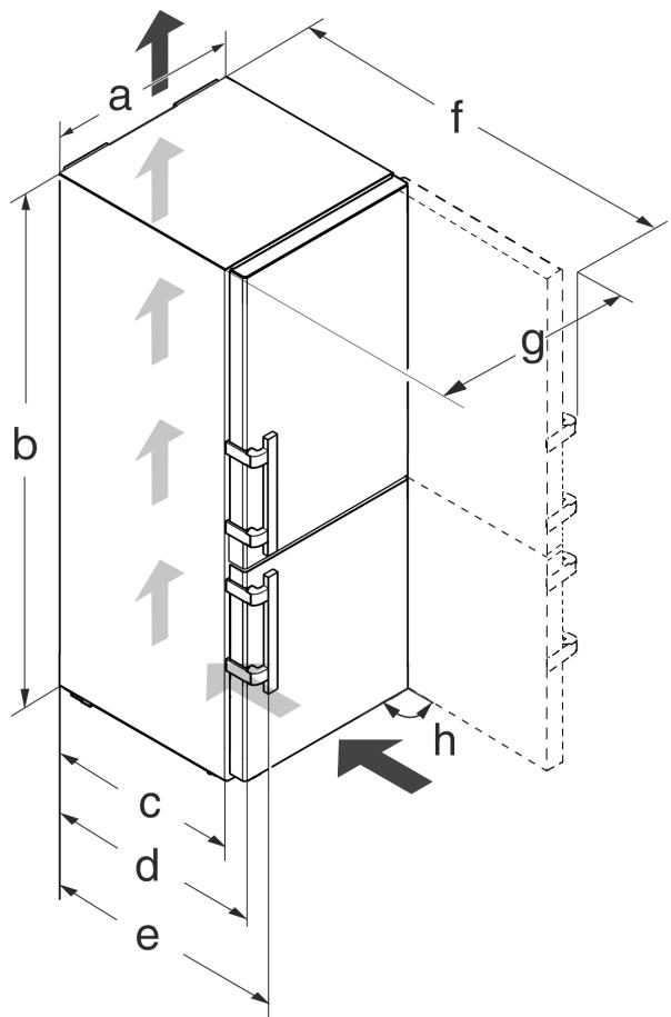
Fig. 2
| Model | a[mm] | b[mm] | c[mm] | d[mm] | e[mm] | f[mm] | g[mm] | h [°] |
| CN(ef)37.. | 600 | 1650 | 600x | 665^x | 709^x | 1223x | 640 | 90 |
| CN(ef/bs/fr/i) 43.. | 1850 | |||||||
| CN(ef)47../48.. | 2010 | |||||||
| CN(ef)57.. | 700 | 1323x | 740 |
^x When using wall spacers, the dimensions increase by 15 mm (see 4.2 Installing the appliance).
1.6 Saving energy
- Pay attention to good ventilation. Do not cover ventilation holes or grids.
-
Always keep the fan air slits clear.
-
Do not install the appliance in direct sunlight, next to an oven, radiator or similar.
- Energy consumption depends on the installation conditions, e.g. the ambient temperature (see 1.2 Appliance range of use). A warmer ambient temperature can increase the energy consumption.
- Open the appliance for as short a time as possible.
- The lower the temperature is set the higher the energy consumption.
- Sort your food: home.liebherr.com/food.
- Keep all food properly packed and covered. This prevents frost from forming.
- Only take food out for as long as necessary so that it doesn't warm up too much.
- Inserting warm food: allow to cool down to room temperature first.
- Thaw frozen food in the refrigerator.
- If you intend to be on holiday for a long time empty the refrigerator and switch it off.
1.7 Example of contents arrangement
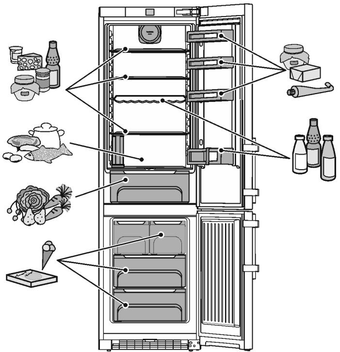
Fig. 3
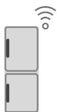
1.8 Smart device
The appliance is ready for integration into a smart home and for extended services. With a SmartDevice Box, you can activate this and other options. This is activated via the MyLiebherr customer portal.
Note
The SmartDevice Box is available for purchase from the Liebherr Household Store (home.liebherr.com).
You will find more information about availability and prerequisites and the individual options on the website, www.smartdevice.liebherr.com.
2 General safety information
Please keep these instructions in a safe place and pass them on to any subsequent owners.*
Please keep these operating instructions in a safe place so you can refer back to them at any time.*
If you pass the appliance on, please hand these operating instructions to the next user.*
Read these operating instructions carefully before use to ensure safe and correct use of the appliance. Follow the instructions, safety instructions and warning messages included at all times. They are important for ensuring you can operate and install the appliance safely and without any problems.
Danger for the user:
- This device can be used by children and people with impaired physical, sensory or mental abilities or with a lack of experience and knowledge provided that they are supervised or have received instruction in the safe use of this device, and about the resulting hazards. Children must not play with this appliance. Cleaning and user maintenance work must not be carried out by children without adult supervision. Children aged between 3 and 8 are allowed to load and unload the appliance. Children below the age of 3 must be kept away from the appliance unless they are under continuous adult supervision.
- The socket must be easily accessible so that the appliance can be disconnected quickly from the electricity in an emergency. It must not be located in the area behind the appliance.
- When disconnecting the appliance from the supply, always take hold of the plug. Do not pull the cable.
- In the event of a fault pull out the mains plug or deactivate the fuse.
- Do not damage the mains power cable. Do not operate the appliance with a defective mains power cable.
- If the supply cord is damaged, it must be replaced by a special cord or assembly available from the manufacturer or its service agent.*
-
Only customer service or other specially trained staff may repair or perform other operations on the appliance.
-
Only assemble, connect and dispose of the appliance according to the instructions.
- Special lights, such as LED lights on the appliance, are used to illuminate the interior of the appliance and are not suitable for room lighting.*
Fire hazard:
- This appliance contains a refrigerant which is environmentally friendly, but flammable. Leaking refrigerant may ignite. It is hazardous for anyone other than an Authorised Service Person to service this appliance. In Queensland, the authorised Service Person MUST hold a Gas Work Authorisation for hydrocarbon refrigerants, to carry out Servicing or repairs where the gas system is being opened or charged.*
- The coolant used (information on the model plate) is ecofriendly but also flammable. Any leaking coolant may ignite.
- Do not damage the refrigerant circuit pipes.
- Do not handle ignition sources inside the appliance.
- Do not use electrical appliances inside the appliance (e.g. steam cleaners, heaters, ice cream makers, etc.).
- If the refrigerant leaks: remove any naked flames or ignition sources from the vicinity of the leakage point. Properly air the room. Inform customer services.
- Do not store explosives or sprays using combustible propellants such as butane, propane, pentane, etc. in the appliance. To identify these spray cans, look for the list of contents printed on the can, or a flame symbol. Gases possibly escaping may ignite due to electrical components.
- Keep burning candles, lamps and other items with naked flames away from the appliance so that they do not set the appliance on fire.
- WARNING: Keep ventilation openings, in the appliance enclosure or in the built-in structure, clear of obstruction.*
- WARNING: Do not use mechanical devices or other means to accelerate the defrosting process, other than those recommended by the manufacturer.*
- WARNING: Do not damage the refrigerant circuit.*
- Please be sure to store alcoholic drinks or other packaging containing alcohol in tightly closed containers. Any alcohol that leaks out may be ignited by electrical components.
Danger of tipping and falling:
- Do not misuse the plinth, drawers, doors etc. as a step or for support. This applies particularly to children.
Danger of food poisoning:
- Do not consume food which has been stored too long.
Danger of frostbite, numbness and pain:
- Avoid prolonged skin contact with cold surfaces or refrigerated/frozen goods or take protective measures, e.g wear gloves.
- Do not consume ice cream, water ice or ice cubes immediately and do not consume them too cold.*
Danger of injury and damage:
- Hot steam can lead to injury. Do not use electrical heating or steam cleaning equipment, open flames or defrosting sprays to defrost.
- Do not use sharp implements to remove the ice.
Risk of crushing:
- Do not hold the hinge when opening and closing the door. Fingers may get caught.
Symbols on the appliance:

This symbol may be located on the compressor. It relates to the oil in the compressor and makes reference to the risk that: Swallowing or inhaling can be fatal. This advice is only relevant to recycling. There is no danger in normal operation.
This symbol is located on the compressor and indicates the danger of flammable materials. Do not remove the sticker.

This or a similar sticker may be located on the rear of the appliance. It refers to the foam-padded panels in the door and/or the housing. This advice is only relevant to recycling. Do not remove the sticker.
Please note the warning messages and other specific advice in the other chapters:
| DANGER | indicates an immediately hazardous situation which will lead to death or serious injuries if it is not avoided. | |
| WARNING | indicates a hazardous situation which may lead to death or serious injuries if it is not avoided. | |
| CAUTION | indicates a hazardous situation which may lead to minor or moderate injuries if it is not avoided. | |
| NOTICE | indicates a hazardous situation which may lead to damage to property if it is not avoided. | |
| Note | indicates useful instructions and tips. |
3 Controls and displays
3.1 Home screen
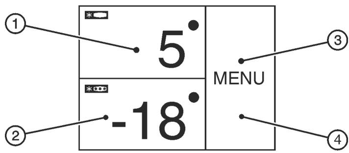
Fig. 4
(1) Fridge compartment field
(2) Freezer compartment field
(3) Menu field
(4) Screen
The home screen is the first screen the user sees. All settings can be made from there.
All functions can be called up by touching the screen and values can be changed.
3.2 Operating structure
Fridge compartment field
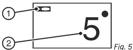
(1) Fridge compartment symbol
(2) Fridge compartment temperature display
The fridge compartment temperature is displayed in the fridge compartment field.
The following settings can be entered:
- Temperature settings
- Switching the fridge compartment on and off
Freezer compartment field
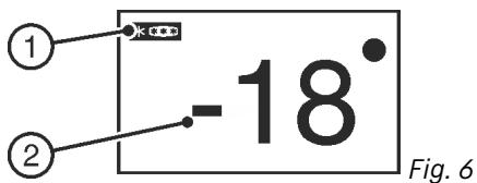
(1) Freezer compartment symbol
(2) Freezer compartment temperature display
The freezer compartment temperature is displayed in the freezer compartment field.
The following settings can be entered:
- Temperature settings
- Switch appliance on/off
The fridge compartment is also turned off when the freezer compartment is turned off.
Menu field
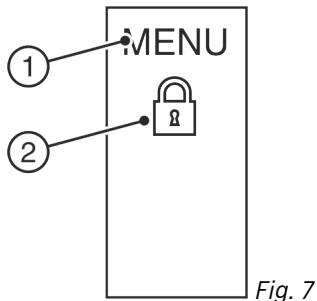
(1) Main menu
(2) Option selected
The menu field gives access to the appliance options and settings. Selected options are also displayed.
3.3 Navigation
Touch the menu to access the individual options. An audible signal sounds after confirming an option or a setting. The display switches to the home screen.
The appliance is operated using the following symbols:

MENU


Standby:
Switches the appliance or temperature zone on.
Menu:
Calls up options.
Minus / Plus:
Changing settings (e.g. adjusting temperatures).
Left/right navigation arrow:
Selects options and navigates through the menu.
You can scroll through the individual options using the navigation arrows. The first option is displayed again after the last one.
Back:
Cancels the selection.
The display switches to the next higher level or to the home screen
OK:
Confirms the selection.
After confirmation the display switches to the home screen.
ON / OFF, START / STOP
Starts/ stops options.
After selecting or cancelling an option the display switches to the home screen.
RESET:
Resets timer.
Access to customer service
Note
If no selection is made after 1 minute the display switches to the home screen.
3.4 Display symbols
Display symbols provide information on the current appliance status:

Up arrows:
The temperature increases.

Down arrows:
The temperature reduces.

Standby:
The appliance or temperature zone is switched off.

Messages:
There are active error messages and reminders.
3.5 Appliance options
You can select or set the following options; explanations and setting options, (see 5 Control):
Symbol
Option


SuperCool ^x


SuperFrost ^x


Fan ^x


SabbathMode


IceMaker ^xx


Child safety device ^x

Temperature unit
^x If the option is selected, the relevant symbol is displayed in the menu field.
If more than 6 selected options are selected only 4 options are displayed in the menu field. The other options are displayed by pressing the bottom navigation arrow. Pressing the navigation arrow repeatedly takes you back to the home screen.
The symbol disappears if the option ends or is disabled.
4 Putting into operation
4.1 Transporting the appliance
▶ Transport the appliance only in suitable packaging.
▶ Transport the appliance upright.
▶ Do not transport the appliance on your own.
4.2 Installing the appliance

WARNING
Fire hazard due to dampness!
If live parts or the mains lead become damp this may cause short circuits.
The appliance is designed for use in enclosed areas. Do not operate the appliance outdoors or in areas where it is exposed to splash water or damp conditions.

WARNING
Improper use!
Fire. If a mains cable/plug comes into contact with the back of the appliance, the mains cable/plug can be damaged by appliance vibrations and this may result in a short circuit.
▶ Stand the appliance so that it is not touched by connectors or main cables.
▶ Do not connect any appliances to sockets in the area of the back of the appliance.
▶ Multi-sockets/power distributors and other electronic appliances (such as halogen transformers) may not be placed and operated at the back of appliances.

WARNING
Leaking coolant and oil!
Fire. The coolant contained in the appliance is eco-friendly, but also flammable. The oil contained in the appliance is flammable. Escaping coolant and oil can ignite if the concentration is high enough and in contact with an external heat source.
▶ Do not damage the pipelines of the coolant circuit and the compressor.

WARNING
Fire hazard and danger of damage!
▶ Do not place appliances emitting heat e.g. microwaves, toasters etc. on the appliance!
NOTICE
Covered vents!
Damage. Appliance can overheat, which can reduce the service life of various parts of the appliance and lead to operational impairments.
▶ Always make sure there is good ventilation.
▶ Always keep vents or ventilation grids in the appliance housing and in the kitchen furniture (fully integrated appliance) unobstructed.
▶ Always keep the fan air vents unobstructed.
NOTICE
Risk of damage due to condensate!
▶ Do not install the appliance directly alongside a further refrigerator/freezer.
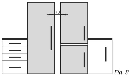
Note
If you have several appliances next to one another, leave a gap of 70mm between appliances. Otherwise condensation will build up between the units.
natural_image
Diagram of a refrigerator with labeled dimensions (70 and Fig. 8), showing front, side, and front views without any text or symbols beyond labels.☐ Before you connect the appliance, report any damage immediately to the delivery company.
☐ The floor of the installation site must be horizontal and even.
☐ Do not install the appliance in direct sunlight, next to an oven, radiator or similar.
☐ Install the appliance with the rear panel up against the wall and always use the supplied wall spacers (see below).
☐ Only ever move the appliance when it is empty.
☐ The surface supporting the appliance must be at the same level as the surrounding floor.
☐ Do not install the appliance on your own.
☐ The more coolant there is in the appliance, the larger the room in which the appliance is installed must be. If the room is too small, any leak may create a flammable mixture of gas and air. For each 8 g of coolant the installation space must be at least 1 m ^3 . Information on the coolant is on the model plate inside the appliance.
▶ Remove the protective film from the outside of the appliance.*
NOTICE
Risk of damage from stainless steel care products!
The stainless steel doors and stainless steel side panels are treated with a premium surface finish.
Stainless steel care products attack these surfaces.

▶ Only use a soft, clean cloth to wipe down finished door and side panel surfaces and painted door and side panel surfaces. To remove heavy dirt, use a little water or neutral detergent. Alternatively, you can use a micro-fibre cloth.
▶ Remove the protective film from the decorative trims.
▶ Remove all transit supports.
Spacers must be used to achieve the declared energy consumption and to prevent condensation in the event of high surrounding humidity. This increases the appliance depth by about 15 mm. The appliance will work perfectly well without the spacers but will have a slightly higher energy consumption.
▶ If your appliance comes with wall spacers, mount these on the back of the appliance, bottom left and right.
natural_image
Technical line drawing of a mechanical assembly with no visible text or symbols▶ Dispose of packaging material (see 4.5 Disposing of packaging).

CAUTION
Risk of injury or damage from the appliance tipping or the door falling open!
If the additional adjustable foot on the base support is not correctly positioned on the floor, there is a risk of the door falling open or the appliance tipping. This can lead to injury or property damage.
▶ Unscrew the additional adjustable foot on the support until it reaches the floor.
▶ Then turn it another 90°.
▶ Align the appliance so that it stands firmly and on a level by applying the accompanying spanner to the adjustable-height feet (A) and using a spirit level.
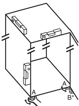
▶ Then support the door: Use saddle wrench SW10 to unscrew the base on mounting block (B) until it makes contact with the ground, then continue turning it for a further 90°.
Note
▶ Clean the appliance (see 6.4 Cleaning the appliance).
If the appliance is installed in a very damp environment, condensate may form on the outside of the appliance.
▶ Always see to good ventilation at the installation site.
4.3 Reversing the door
If necessary, you can change the way the door opens:
Ensure that the following tools are available:
Torx® 25 (T25)
Torx® 15 (T15)
☐ Slotted screwdriver
Open-ended wrench SW10
Spirit level
☐ Open-ended wrench supplied with the T25 tool
☐ If necessary, a cordless screwdriver
☐ Get a stepladder if necessary
☐ If necessary, a second person for assembly
▶ Remove any food from the door racks before removing the door, so that no food falls out.
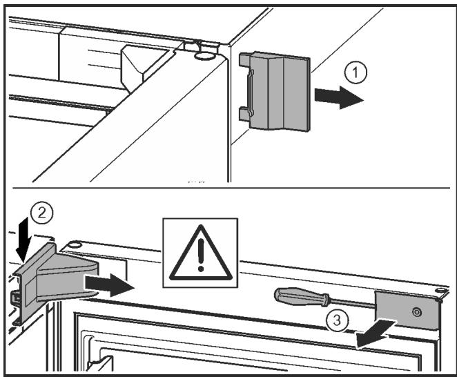
Fig. 9
▶ Open the door.
NOTICE
Risk of damage!
If the door seal is damaged, the door may fail to close properly and the cooling will be inadequate.
▶ Do not damage the door seal with the screwdriver!
▶ Remove the outer cover. Fig. 9 (1)
▶ Disengage and release the bearing bracket cover. Remove the bearing bracket cover. Fig. 9 (2)
▶ Unlatch the panel with a slotted screwdriver and swivel it to one side. Fig. 9 (3)
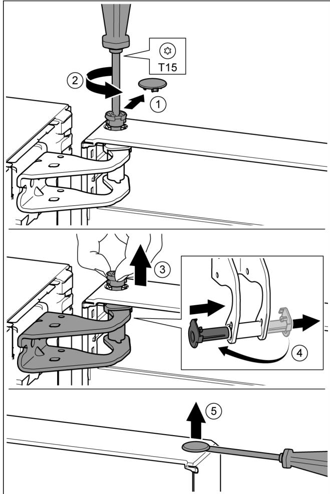
Fig. 10

CAUTION
Risk of injury if the door tips!
▶ Take good hold of the door.
▶ Set down the door carefully.
▶ Carefully remove the protective cover. Fig. 10 (1)
▶ Undo the bolt a little with a T15 screwdriver. Fig. 10 (2)
▶ Hold the door and remove the bolts with your fingers. Fig. 10 (3)
▶ Pull the bearing bush out of the guide. Insert from the other side and click into place. Fig. 10 (4)
▶ Lift the door and set it aside.
▶ Carefully lift the plugs out of the door bearing bush with a slotted screwdriver and remove. Fig. 10 (5)
4.3.2 Removing the lower door
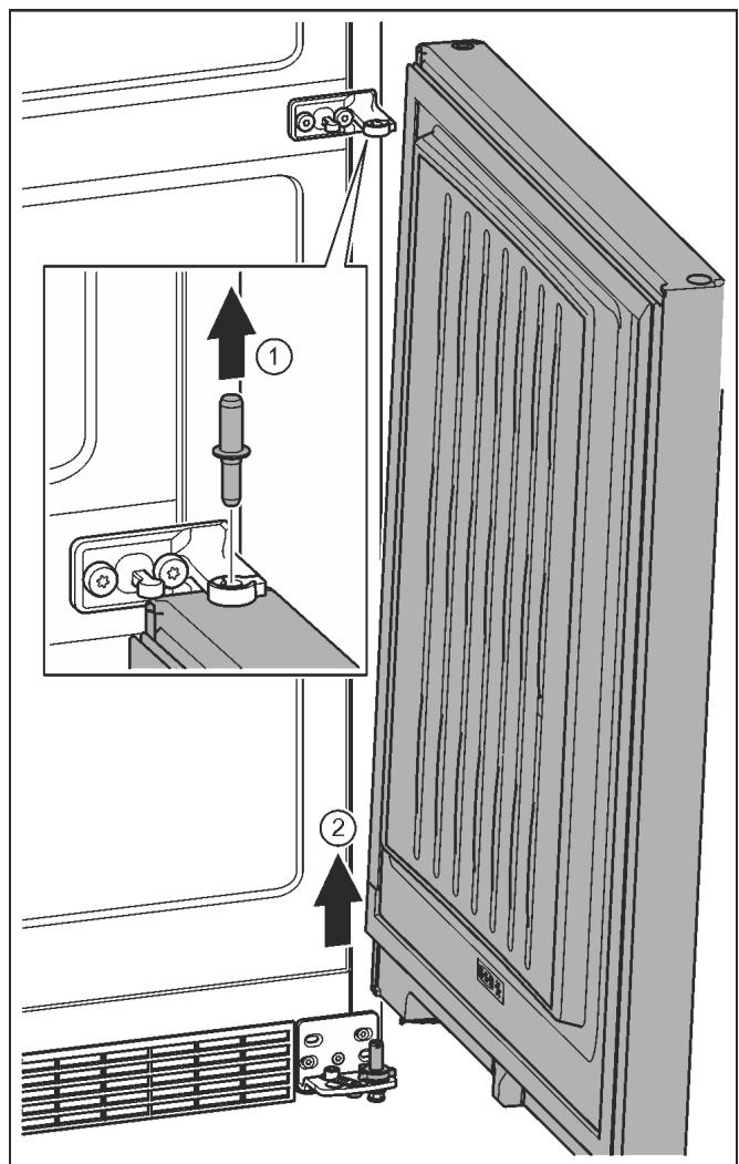
Fig. 11

CAUTION
Risk of injury if the door tips!
▶ Take good hold of the door.
▶ Set down the door carefully.
▶ Pull out the bolts towards the top. Fig. 11 (1)
▶ Swing the door out, pull it upwards and set it aside. Fig. 11 (2)
4.3.3 Moving the upper bearing parts to the other side
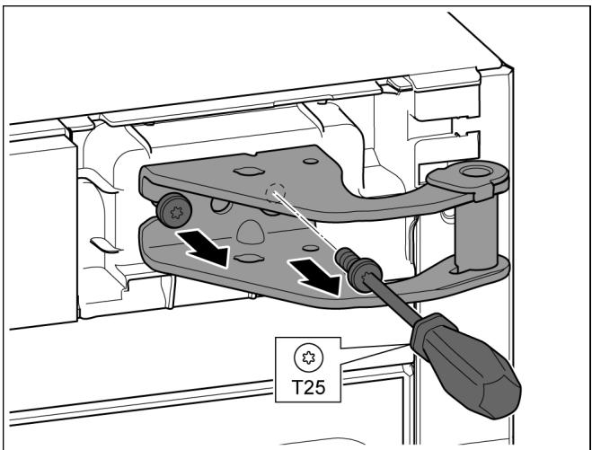
Fig. 12
▶ Remove both screws with the T25 screwdriver.
▶ Lift and remove the bearing bracket.
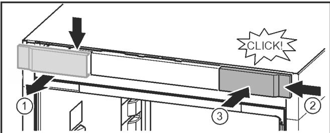
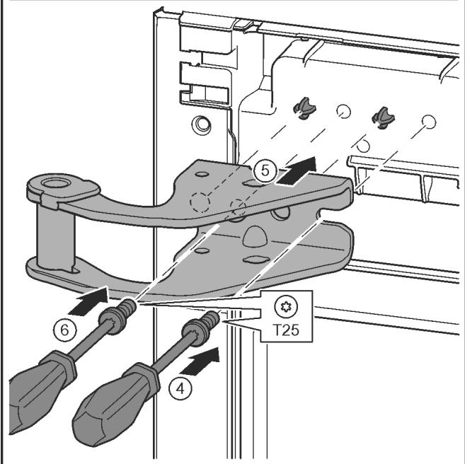
Fig. 13
▶ Release the cover and remove from the side. Fig. 13 (1)
▶ Rotate the cover 180^ and clip onto the other side from the right. Fig. 13 (2)
▶ Click the cover into place. Fig. 13 (3)
▶ Position the screw with a T25 screwdriver. Fig. 13 (4)
▶ Position the upper bearing bracket. Fig. 13 (5)
▷ Place the pins in the provided screw holes.
▶ Tighten the screw. Fig. 13 (4)
▶ Insert the screw with a T25 screwdriver and tighten. Fig. 13 (6)
4.3.4 Moving the central bearing parts to the other side
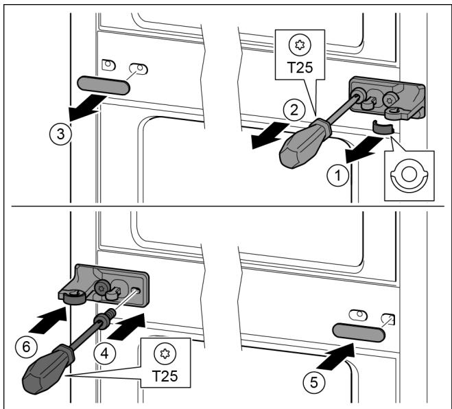
Fig. 14
▶ Remove the washer. Fig. 14 (1)
▶ Remove the screws with the T25 screwdriver. Fig. 14 (2)
▶ Remove the cover carefully. Fig. 14 (3)
▶ Screw the bearing bracket and the film rotated 180^ firmly onto the other side. Fig. 14 (4)
▶ Attach the cover rotated 180^ onto the other side. Fig. 14 (5)
▶ Push the washer in from the front. Fig. 14 (6)
4.3.5 Moving the lower bearing parts to the other side
Fig. 15
▶ Lift the bearing pin completely upward and remove. Fig. 15 (1)
▶ Undo the screws with a T25 screwdriver and remove the bearing bracket Fig. 15 (2)
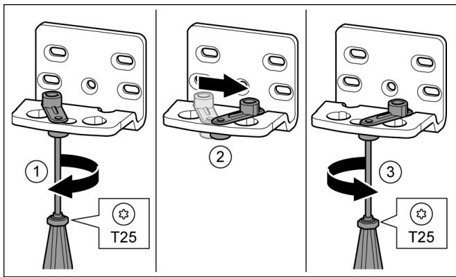
Fig. 16
▶ Loosen the screw using a T25 screwdriver. Fig. 16 (1)
▶ Lift the door closure aid and turn it 90° to the right in the hole. Fig. 16 (2)
▶ Tighten the screw using a T25 screwdriver. Fig. 16 (3)
natural_image
Diagram of a heat exchanger or cooling system with cooling fins and airflow direction indicated (no text or symbols)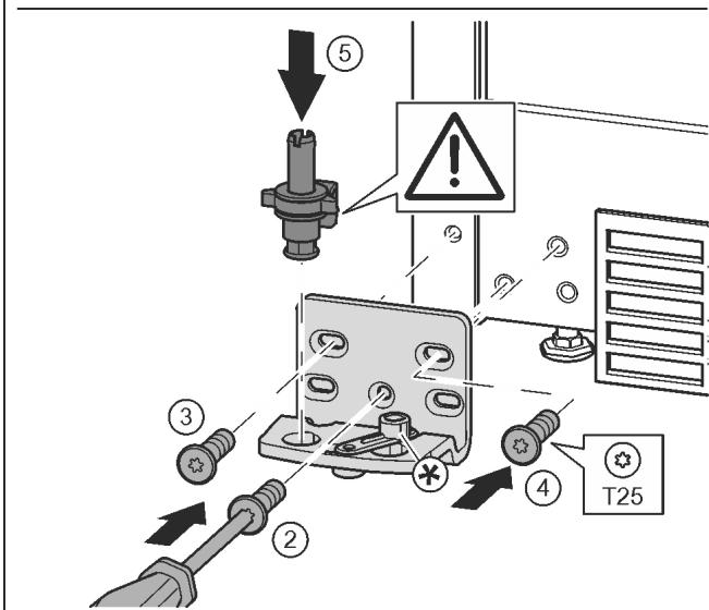
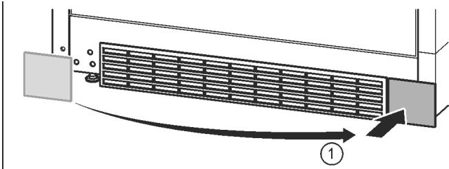
Fig. 17
▶ Remove the cover and fix it on the other side. Fig. 17 (1)
▶ Place the bearing bracket on the other side and screw in with the aid of a T25 screwdriver. Start with screw 2 at the bottom in the middle. Fig. 17 (2)
▶ Screw in screws 3 and 4. Fig. 17 (3, 4)
▶ Insert the bearing pin completely. Make sure that the catch mechanism is pointing to the rear. Fig. 17 (5)
4.3.6 Moving the door bearing parts to the other side
Bottom door
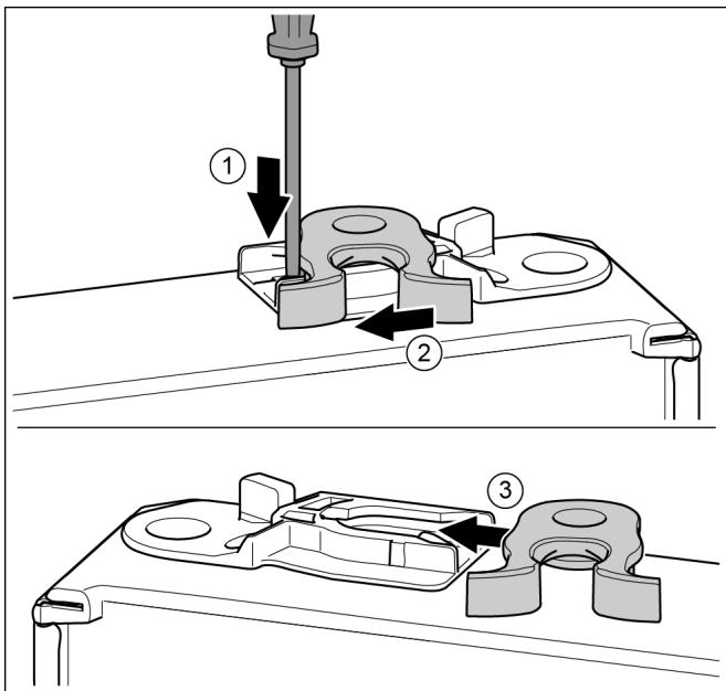
Fig. 18
▶ Underside of door faces upwards: Turn the door.
▶ Push the tab downwards with a slotted screwdriver. Fig. 18 (1)
▶ Pull the door latch out of the guide. Fig. 18 (2)
▶ Push the door latch into the guide on the other side. Fig. 18 (3)
▶ Upper side of door faces upwards: Turn the door.
Top door
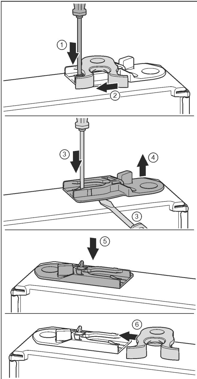
Fig. 19
▶ Underside of door faces upwards: Turn the door.
▶ Push the tab downwards with a slotted screwdriver. Fig. 19 (1)
▶ Pull the door latch out of the guide. Fig. 19 (2)
▶ Pull out the guide bush: Press the tab with a slotted screwdriver and, at the same time, insert the slotted screwdriver under the guide bush. Fig. 19 (3, 4)
▶ Slide the guide bush included in the scope of supply to the other side of the housing. Fig. 19 (5)
▶ Push the door latch into the guide. Fig. 19 (6)
▶ Upper side of door faces upwards: Turn the door.
4.3.7 Moving the handles to the other side
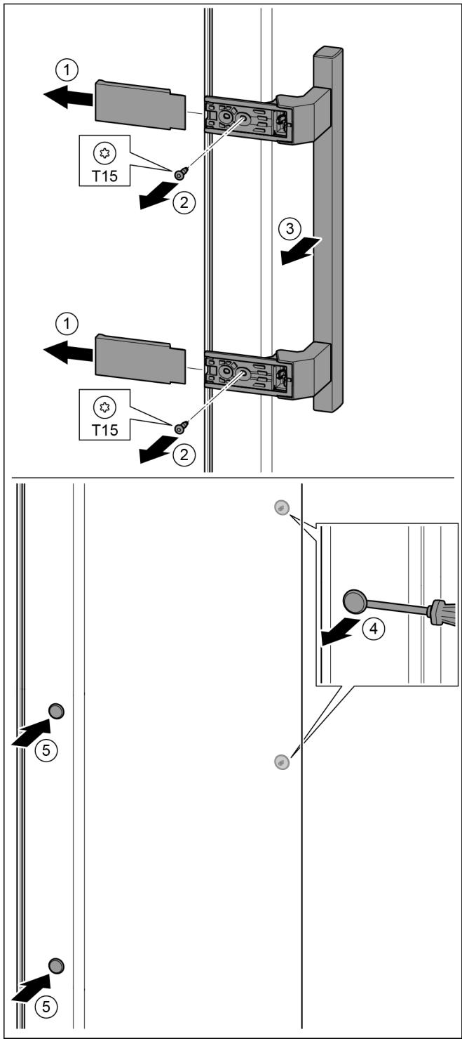
Fig. 20
▶ Pull off the cover. Fig. 20 (1)
▶ Remove the screws with the T15 screwdriver. Fig. 20 (2)
▶ Remove the handle. Fig. 20 (3)
▶ Carefully lift up the side plugs with a slotted screwdriver and pull them out. Fig. 20 (4)
▶ Insert the plugs again on the other side. Fig. 20 (5)
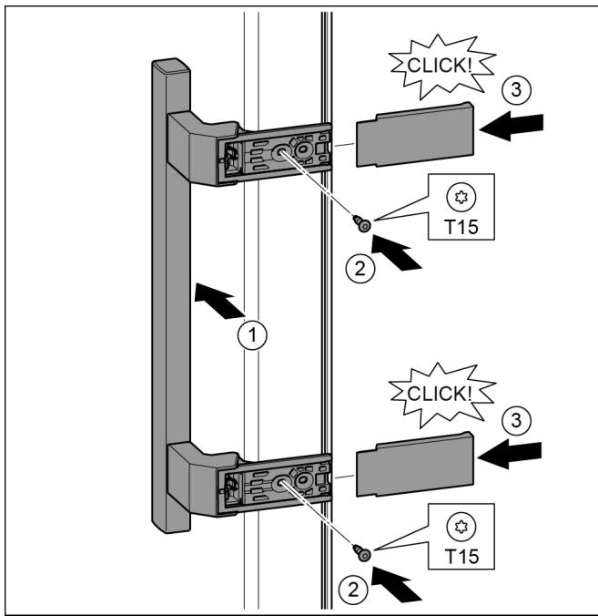
Fig. 21
▶ Position the handle on the other side. Fig. 21 (1)
▷ The screw holes must be exactly above each other.
▶ Tighten the screws with the T15 screwdriver. Fig. 21 (2)
▶ Position the covers on the side and push in. Fig. 21 (3)
▷ Ensure that it clicks into place.
Fig. 22
▶ Carefully lift up the plugs with a slotted screwdriver and remove them. Fig. 22 (1)
▶ Insert the plugs again on the other side of the door. Fig. 22 (2)
▶ Position the door from above onto the lower bearing pins. Fig. 22 (3)
▶ Insert the centre bearing pin through the centre bearing bracket into the lower door. Make sure that the catch mechanism is pointing to the rear. Fig. 22 (4)
▶ Place the door on the centre bearing pins.
▶ Align the top of the door with opening in the bearing bracket. Fig. 23 (1)
▶ Insert the bolt and tighten with a T15 screwdriver. Fig. 23 (2)
▶ Fit the protective cover to protect the door: Insert the protective cover and check that it is attached to the door. If not, insert the bolt fully. Fig. 23 (3)
▶ Insert the plugs. Fig. 23 (4)
4.3.10 Aligning the doors

WARNING
Risk of injury due to the door dropping out! If the bearing parts are not screwed into place firmly enough, the door may drop out. This may lead to severe injuries. What is more, the door may not close and therefore the appliance may fail to cool properly.
▶ Screw the turn hinges firmly into place with 4 Nm.
▶ Check all of the screws and retighten if necessary.
Align the doors flush with the appliance housing using the two oblong holes in the lower bearing bracket and centre bearing bracket if needed. To do this undo the middle screw in the bottom bearing bracket with the T25 tool supplied. Undo the remaining screws a little with the T25 tool or with a T25 screwdriver and align using the slotted holes. Undo the screws in the middle bearing bracket with the T25 tool and align the middle bearing bracket using the slotted holes.
▶ Support the door: Take off the adjustable foot on the bearing bracket using the open-ended wrench SW10 until it comes into contact with the floor, then turn an additional 90°.
4.3.11 Fit the covers
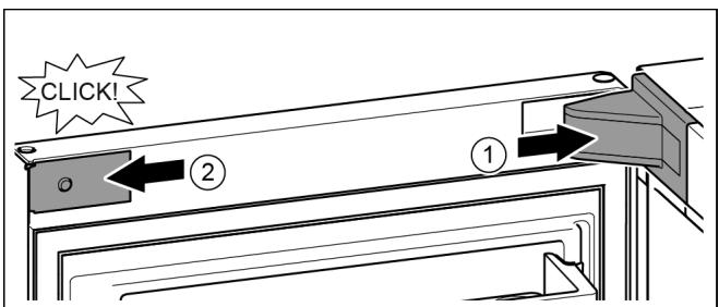
Fig. 24
The door is open 90°.
▶ Position the bearing bracket and engage. If necessary push apart carefully. Fig. 24 (1)
▶ Position the panel on the side and click into place. Fig. 24 (2)
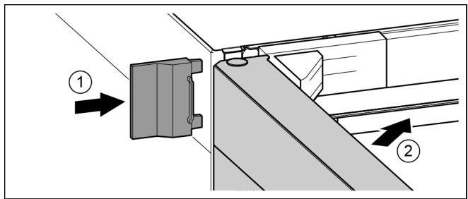
Fig. 25
▶ Slide on the external cover. Fig. 25 (1)
▶ Close the upper door. Fig. 25 (2)
4.4 Sliding into the row of units
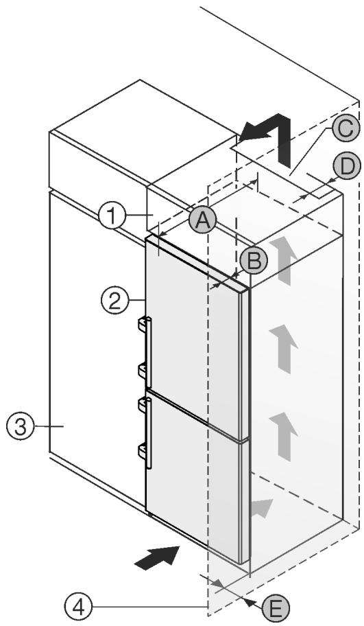
Fig. 26
For 600 mm-wide appliances:*
| A [mm]* | B [mm]* | C [cm2]* | D [mm]* | E [mm]* |
| 665 ^x | 65 | min. 300 | min. 50 | min. 46 |
For 700 mm-wide appliances:*
| A [mm]* | B [mm]* | C [cm2]* | D [mm]* | E [mm]* |
| 665 x | 65 | min. 300 | min. 50 | min. 46 |
^x If using wall spacers, add 15 mm (see 4.2 Installing the appliance).
These dimensions apply to an opening angle of 90^ . Clearances vary depending on the opening angle.
The appliance can be built into kitchen units. A top cupboard Fig. 26 (2) can be added above the appliance in order to bring the appliance Fig. 26 (1) up to the height of the fitted kitchen units.
The appliance can be installed right next to the kitchen cabinet Fig. 26 (3). The appliance must protrude by depth Fig. 26 (B) from the front of the cabinet so that the doors can be opened fully. The appliance may protrude further depending on the depth of the kitchen cabinets and whether wall spacers are used.
NOTICE
Danger of overheating due to insufficient air ventilation! The compressor may be damaged if there is insufficient air ventilation.
▶ Take care to ensure adequate air ventilation.
▶ Observe the ventilation requirements.
Ventilation requirements:
- There are spacer fins at the back of the appliance to provide adequate ventilation. Make sure these do not end up in recesses or openings.
- At the back of the top cabinet, there must be an air outlet shaft with depth Fig. 26 (D), spanning the entire width.
- The ventilation shaft Fig. 26 (C) must be observed under the ceiling.
- The wider the ventilation clearance, the more efficiently the appliance will run.
If the appliance is installed with the hinges next to a wall Fig. 26 (4), the distance Fig. 26 (E) between the appliance and the wall must be observed. This is how far the handle protrudes when the door is open.
4.5 Disposing of packaging

WARNING
Danger of suffocation due to packing material and plastic film!
▶ Do not allow children to play with packing material.
The packaging is made of recyclable materials:
- corrugated board/cardboard
- expanded polystyrene parts
- polythene bags and sheets
- polypropylene straps
- nailed wooden frame with polyethylene panel*
▶ Take the packaging material to an official collecting point.

4.6 Connecting the appliance

WARNING
Failure to connect properly
Fire hazard.
▶ Do not use an extension cable.
▶ Do not use distributor blocks.
NOTICE
Failure to connect properly
Damage to the electronics.
▶ Do not connect the appliance to a stand-alone inverter, e.g. solar power systems and petrol generators.
▶ Do not use an energy saving plug.
Note
Only use the power connection lead supplied.
▶ A longer power connection lead can be ordered from Customer Service.
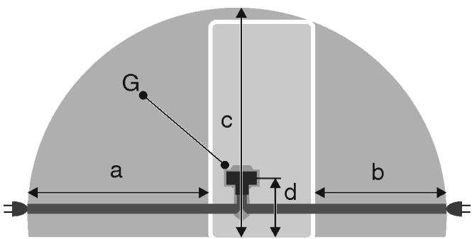
Fig. 27
For 600 mm wide appliances:*
| a* | b* | c* | d* | G* |
| ~ 1800 mm | ~ 1400 mm | ~ 2100 mm | ~ 200 mm | Appliance plugs |
For 700 mm wide appliances:*
| a* | b* | c* | d* | G* |
| ~ 1750 mm | ~ 1350 mm | ~ 2100 mm | ~ 200 mm | Appliance plugs |
Ensure that the following conditions are met:
- The type of current and voltage at the installation site correspond to the information on the model plate (see 1 Appliance at a glance).
- The socket is earthed according to the regulations and fused.
- The fuse tripping current is between 10 and 16 A.
- The socket is easily accessible.
- The socket is outside the back of the appliance area in the specified area Fig. 27 (a, b, c).
▶ Check the electrical connection.
▶ Insert the appliance plug Fig. 27 (G) into the back of the appliance. Ensure that it clicks into place.
▶ Connect the power plug to the power supply.
▷ The Liebherr logo appears on the screen.
▷ The display switches to the standby symbol.
4.7 Switching on the appliance
Note
If the appliance is in demo mode, DEMO appears on the homescreen.
▶ Disable demo mode (see 7 Malfunctions).
Note
The manufacturer recommends:
▶ Store frozen produce at -18 °C or colder.
Connect and switch on appliance approx. 10 hours before loading it for the first time.
4.7.1 Switch on appliance
If the standby symbol is displayed over the whole screen:
▶ Press the standby symbol.
▷ The appliance is switched on. The display switches to the home screen.
▷ The appliance is set to the displayed temperatures. This is shown by down arrows.
If the standby symbol is displayed in the fridge compartment and the freezer compartment fields:
▶ Press the Standby symbol in the freezer compartment field or the fridge compartment field.
▷ The appliance is switched on.
The appliance is set to the displayed temperatures. This is shown by down arrows.
If the screen is black:
▶ Touch the screen.
▷ The standby symbol appears on the whole screen.
▶ Press the standby symbol.
▷ The appliance is switched on. The display switches to the home screen.
▷ The appliance is set to the displayed temperatures. This is shown by down arrows.
4.7.2 Switching the fridge compartment on
The standby symbol is displayed in the fridge compartment field.
▶ Press the standby symbol in the fridge compartment field.
▷ The fridge compartment is switched on.
The fridge compartment is set to the displayed temperature. This is shown by down arrows.
4.8 SmartDevice box
SmartDevice box: Start-up instructionswww.smartdevice.liebherr.com/install
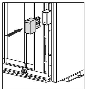
If the SmartDevice box (SDB) is inserted correctly the menu below appears. The device is supplied with WLAN activated.
To use more WiFi options, open the WIFI menu.
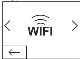
Fig. 28
▶ Press WIFI.
▷ The WIFI menu opens.
Turning on/off WiFi
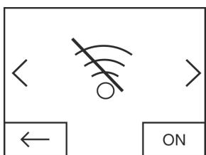
Fig. 29
▶ Use the slider at the bottom right to turn on/off WIFI
▷ Slider to OFF = WIFI is disabled.
▷ Slider to ON = WIFI is enabled.
WIFI INFO
Call up the status of the SmartDevice box.
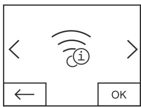
Fig. 30
▶ Press the OK button.
The WIFI INFO screen opens.
▷ The following statuses can be displayed:
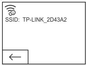
Fig. 31
▷ SSID: ***WPS*** = The SmartDevice box is in WPS mode for 3 minutes. An automatic connection to the SmartDevice box can be established via the router.
▷ SSID: LHSDB_xxxxxxxxxxx = the SmartDevice box is in manual connection mode for 30 minutes. The SmartDevice box transmits a private network to which you can connect to send WLAN data.
▷ SSID: empty = The SmartDevice box is in sleep mode. Please reset the WIFI and connect your SmartDevice box to the home network.
▷ SSID: TP-LINK_2D43A2 or Fritz!Box7069 = The SmartDevice box is connected to the home network.
WIFI RESET
Resetting the SmartDevice box to the default settings.
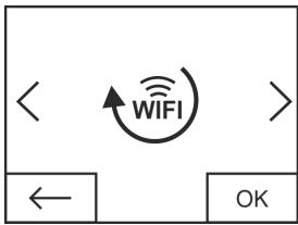
Fig. 32
▶ Confirm with OK.
The SmartDevice box is reset to the default settings.
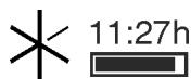
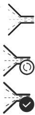
Showing the WiFi status on the Home screen
Status: WiFi on & connected
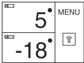
Fig. 33
▶ The WiFi indicator is white.
▷ WiFi is on.
The home network and the Liebherr server are connected.
Status: WiFi on & connecting
▶ The WiFi display shows a clock.
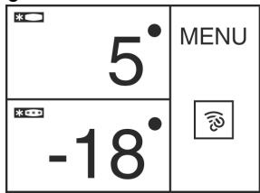
Fig. 34
▷ WiFi is on.
▷ There is no connection to the home network and/or the Liebherr server.
Status: WiFi on & disconnected
▶ The WiFi display shows a warning sign.
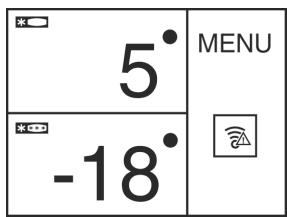
Fig. 35
▷ WiFi is on.
The SmartDevice box is either not connected to a network or the SmartDevice box is connected to a network but the network cannot be found, e.g. switched off at night.
4.9 Inserting the FreshAir filter.
The supplied FreshAir filter can be used for optimum air quality.
The intake is located at the top of the appliance, (see 1 Appliance at a glance)
▶ Remove cover.
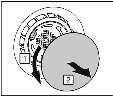
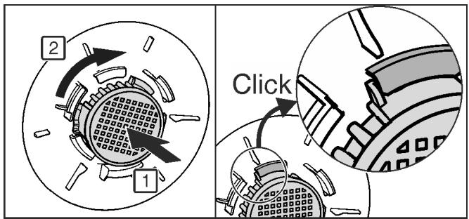
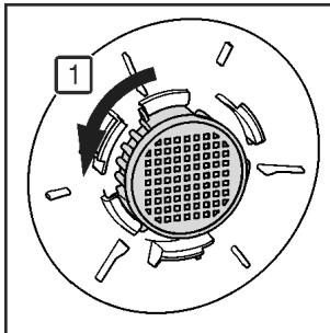
Fig. 36
▶ FreshAir-Insert the filter in the cover and turn it clockwise.
▶ Ensure that the filter clicks into place.
▶ Replace the cover again.
Setting the timer
▶ Press menu.
▶ Press the navigation arrows until the FreshAir filter is displayed.
▶ Press the FreshAir filter symbol.
▶ Press ON.
The timer is set. After the interval has expired a message prompts you to change the FreshAir filter.
4.10 Setting the clean ventilation grid timer
The ventilation grid must be cleaned at least once a year for sufficient ventilation. The timer can be set as a reminder.
▶ Press menu.
▶ Press the navigation arrows until the ventilation grid is displayed.
▶ Press the ventilation grid symbol.
▶ Press ON.
▷ The timer is set. After the interval has expired a message prompts you to clean the ventilation grid.

5 Control
5.1 Changing the temperature unit
The temperature display can be switched from ^ C to ^ F.
▶ Press menu.
▶ Press the navigation arrow until °C is displayed.
▶ Press °F.
▷ The temperature is displayed in °F.
Switch from °F to °C in the same way.
5.2 Child proofing
The child-proofing function enables you to make sure that the appliance is not inadvertently switched off by playing children.


5.2.1 Switching on the child safety device
▶ Press menu.
▶ Press the navigation arrows until the child safety device is displayed.
▶ Press ON.
▷ The child safety device is switched on.


5.2.2 Switching the child safety device off
▶ Press menu.
▶ Press the navigation arrows until the child safety device is displayed.
▶ Press OFF.
▷ The child safety device is switched off.

5.3 SabbathMode
This function meets the religious requirements on the Sabbath or Jewish festivals. Turn on SabbathMode to switch off certain controls. After setting up SabbathMode, you no longer need to worry about indicator lights, figures, symbols, displays, alarms or fans. The thawing cycle only works for the specified time without taking account of fridge use. After a power cut the appliance automatically returns to SabbathMode.
There is a list of Star-K certified appliances at www.stark.org/appliances.

WARNING
Danger of food poisoning.
If there is a power cut while the appliance is in SabbathMode, this message is not saved. Once power is restored, the appliance continues in SabbathMode. When this mode is over no message about the power cut is displayed on the temperature display.
If there was a power cut during SabbathMode:
▶ Check the food for quality. Do not eat the food if it has thawed.
- All functions are locked until SabbathMode is switched off.
- If functions such as SuperFrost, SuperCool, Ventilation, etc. are activated when SabbathMode is on, they remain active.
- The IceMaker does not work.*
- No audible signals are emitted and the temperature display does not indicate any warnings or settings (such as a temperature alarm or door alarm).
- The internal light is off.
5.3.1 Switching SabbathMode on.
▶ Press menu.
▶ Press the navigation arrow until SabbathMode is displayed.
▶ Press ON.
▷ SabbathMode is switched on. Only the SabbathMode symbol appears on the screen.


SabbathMode switches off automatically after 120 hours if it has not already been switched off manually. The display switches to the home screen.
5.3.2 Switch off the SabbathMode
▶ Touch the screen.
▶ Press OFF.
▷ SabbathMode is switched off.

5.4 Refrigerator compartment
The natural circulation of air in the refrigerator compartment results in zones differing in temperature. It is coldest directly above the vegetable drawers and at the rear wall. It is warmest at the top front of the compartment and in the door.
5.4.1 Refrigerating food
Note
The energy consumption increases and the cooling performance decreases if the ventilation is inadequate.
▶ Always keep the air slits of the fan free.
▶ Store perishable foods such as ready-to-eat meals, meat and sausages in the coldest area. Place butter and preserves in the top area and in the door. (see 1 Appliance at a glance)
▶ Use reusable plastic, metal, aluminium, glass containers and foil wrap to store food.
▶ Always store raw meat and fish in clean, sealed containers on the bottom shelf of the refrigerator, to prevent them coming into contact with or dripping onto other foods.
▶ Foods that easily absorb or give off smell or taste, as well as liquids, should be stored in sealed containers or covered.
▶ Use the front area of the base shelf only to temporarily set down refrigerated foods, for example while rearranging or sorting the contents. Remember not to leave refrigerated foods here as they could shift to the back or tip over when you close the door.
▶ Do not pack foods too closely together, as the air needs to circulate.
5.4.2 Setting the temperature
The temperature depends on the following factors:
- the frequency of opening the door
- how long the door is open for
- the room temperature of the installation location
- the type, temperature and quantity of the food
The temperature can be set from 9^ C to 1^ C.
Recommended temperature setting: 5 °C
▶ Press the fridge compartment field.
▷ The following screen is displayed:
Setting a higher temperature:
▶ Press plus.
Setting a lower temperature:
▶ Press minus.
The minus symbol is greyed out when the coldest temperature is selected.
The plus symbol is greyed out if it is pressed again after selecting the hottest temperature. The standby symbol is displayed on the screen.
▶ Confirm the required temperature with OK.
▷ The display switches to the home screen.
▷ The selected temperature is displayed.
▷ Up or down arrows indicate the change in temperature. The arrows are greyed out when the target temperature is reached.
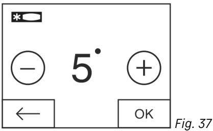
5.4.3 SuperCool
With SuperCool you switch to the highest cooling performance to reach lower cooling temperatures. Use SuperCool, to rapidly cool large amounts of food.
When SuperCool is activated, the fan* may run. The appliance operates with maximum cooling performance, which means that the noise of the refrigeration unit may be temporarily louder.
The SuperCool function uses slightly more energy.
Switching on SuperCool
▶ Press menu.
▶ Press the navigation arrow until SuperCool is displayed.
▶ Press the SuperCool symbol.
▷ The following screen is displayed:
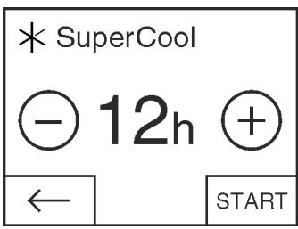
Fig. 38
The running time can be set to four levels.
Setting the running time:
▶ Press plus or minus.
The minus symbol is greyed out when the lowest level is selected.
The plus symbol is greyed out when the highest level is selected.
▶ Confirm the required running time with START.
▷ The display switches to the home screen.
▷ SuperCool is selected.
The remaining running time and the SuperCool symbol are displayed in the fridge compartment field.
▷ The lowered temperature is shown by the down arrows.

▷ After the remaining running time has elapsed the appliance returns to normal mode. The temperature is set to the preset value again. Up arrows show the temperature increase.
Switching SuperCool off ahead of schedule
▶ Press menu.
▶ Press the navigation arrow until SuperCool and the remaining running time are displayed.
▶ Press on the remaining running time.
▶ Press STOP.
▷ SuperCool is switched off.
▷ The temperature is set to the preset value again. Up arrows show the temperature increase.
5.4.4 Fan
With the fan you can rapidly cool large quantities of fresh food or achieve a relatively even distribution of temperature across all the storage levels.

The forced-air cooling is to be recommended:
- at high room temperature (above33 °C)
- at high humidity
The forced-air cooling uses slightly more energy. To save energy, the fan switches off automatically when the door is open.
▶ Press menu.
▶ Press the navigation arrows until the fan is displayed.
▶ Press ON.
▷ The fan is switched on.
▶ Press menu.
▶ Press the navigation arrows until the fan is displayed.
▶ Press OFF.
▷ The fan is switched off.
5.4.5 Shelves
Moving or removing shelves
The shelves are prevented from being pulled out accidentally by pull out stops.
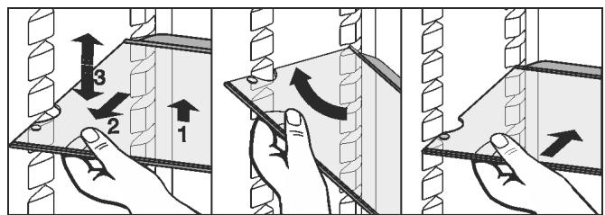
Fig. 39
▶ Lift the shelf and pull forward a little.
▶ Adjust the height of the shelf. To do this move the slots along the supports.
▶ In order to remove the shelf fully, place it at a slant and pull out towards the front.
▶ Insert shelf with the raised edge pointing upwards at the back.
▷ The food does not freeze onto the rear wall.
▷ Food is prevented from falling out.
Do not store any goods on the humidity regulation plate of the bottom shelf.
Dismantling shelves
▶ The shelves be dismantled cleaning.
can for
natural_image
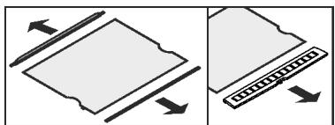
Two diagrams showing a document being inserted into a notebook and then placed on a keyboard (no text or symbols present)5.4.6 Using the sectioned shelf
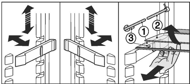
Fig. 40
Adjusting the height:
▶ Pull the glass plates out forwards one by one.
▶ Remove the support from the catch mechanism and click into place at the required height.
Using both shelves:
▶ Lift the top glass plate and pull the bottom glass plate forwards.
▷ The glass plate (1) with the pull out stops must be at the front so that the stops (3) point downward.
5.4.7 Door racks
Moving the storage rack
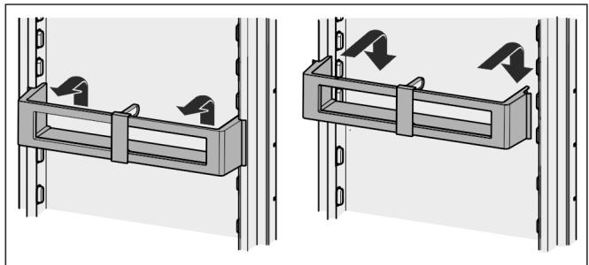
natural_image
Two technical diagrams showing mechanical assembly with arrows indicating motion, no text or symbols presentFig. 41
Dismantling door racks
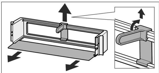
natural_image
Technical diagram of a mechanical assembly with directional arrows indicating motion (no text or symbols)Fig. 42
▶ The door racks can be dismantled for cleaning.
5.4.8 Using the bottle holder
▶ To avoid the bottles tipping over, push the bottle holder along.
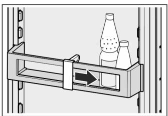
natural_image
Diagram of a mechanical device with two bottles and a directional arrow, no text or symbols present5.4.9 Egg tray
You can take out and rotate the egg tray. You can use the two parts of the egg tray to mark different use-by dates, for example.
natural_image
Isometric illustration of two rectangular plastic crates with circular holes, one with a triangular top and the other with an arrow indicating rotation (no text or symbols)▶ Use the top part to store e.g. chicken eggs.
▶ Use the bottom part to store quails' eggs.
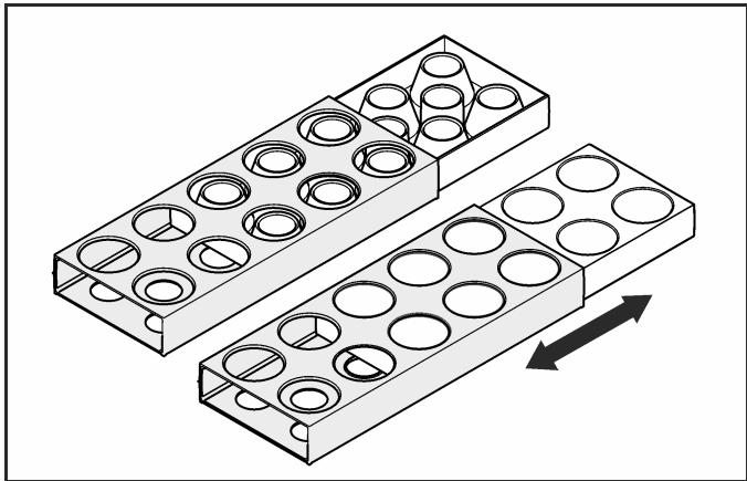
5.4.10 BioCool box
Controlling humidity
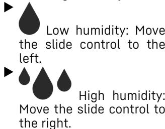
natural_image
Diagram showing two parallel channels with water droplets and bidirectional arrow, no text or symbols presentRemoving the BioCool box
For 600 mm wide appliances:*
natural_image
Diagram of a refrigerator drawer with an arrow indicating direction (no text or symbols present)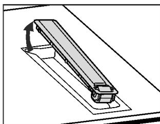
natural_image
Diagram of a mechanical lever system with a rotating arrow indicating motion (no text or symbols)Fig. 43 *
▶ BioCool box and roller plates can be removed for cleaning.*
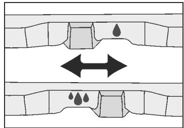
For 700 mm wide appliances:*
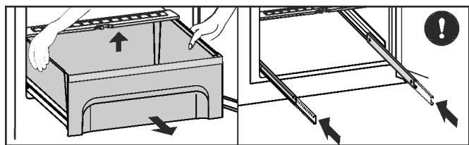
Fig. 44 *
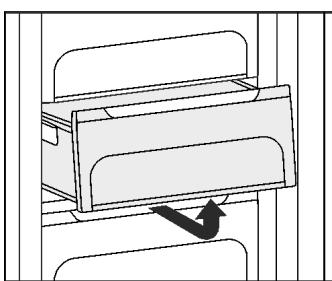
▶ Pull out the drawer, lift it at the back and remove it from the front.*
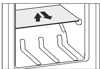
▶ Slide the rails in.*
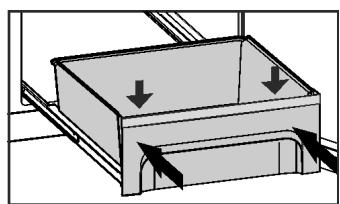
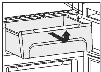
natural_image
Diagram of a mechanical device with arrows indicating force or movement (no text or symbols)Fig. 45 *
▶ When sliding in the drawer, place it on the rails and slide inwards until you hear it click into place at the back.*
▶ BioCool box can be removed for cleaning.*
5.5 Freezer compartment
You can store frozen food, make ice cubes and freeze fresh food in the freezer compartment.
5.5.1 Freezing food
The rating plate indicates the maximum quantity of fresh food you can freeze within 24 hours (see 1 Appliance at a glance) under “Freezing capacity ... kg/24h”.
Each drawer can hold a max. of 25 kg of frozen food.
For 600 mm wide appliances:*
The shelves can each be loaded with 35 kg of frozen food.*
For 700 mm wide appliances:*
The shelves can each be loaded with 55 kg of frozen food.*
Closing the door creates a vacuum. After closing, wait for around 1 minute, then the door will be easier to open.

CAUTION
Risk of injury due to broken glass!
Bottles and cans containing drinks may burst when being frozen. This applies particularly to sparkling drinks.
▶ Do not freeze bottles and cans containing drinks!
So that the food is rapidly frozen through to the core, do not exceed the following quantities per pack
- Fruit, vegetables up to 1 kg
- Meat up to 2.5 kg
▶ Pack the food in portions in freezer bags, reusable plastic, metal or aluminium containers
5.5.2 Storage life
| Standard values for the storage life of various types of food in the freezer compartment: | |
| Ice-cream | 2 to 6 months |
| Sausage, ham | 2 to 6 months |
| Bread, bakery products | 2 to 6 months |
| Game, pork | 6 to 10 months |
| Fatty fish | 2 to 6 months |
| Lean fish | 6 to 12 months |
| Cheese | 2 to 6 months |
| Poultry, beef | 6 to 12 months |
| Vegetables, fruit | 6 to 12 months |
The values indicated for storage life are standard ones.
5.5.3 Thawing food
- in the refrigerator compartment
- in a microwave oven
- in a conventional or fan oven
- at room temperature
▶ Remove only as much food as is required. Use thawed food as quickly as possible.
▶ Food once thawed should be re-frozen only in exceptional cases.
5.5.4 Setting the temperature
The temperature depends on the following factors:
- the amount of times the door is opened
- how long the door is open for
- the room temperature of the installation site
- the type, temperature and amount of food
The temperature can be set from -26 ^ to -16 ^ .
Recommended temperature setting: -18 °C
▶ Press the freezer compartment field.
▷ The following screen is displayed:
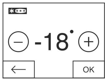
Fig. 46
Setting a higher temperature:
▶ Press plus.
Setting a lower temperature:
▶ Press minus.
The minus symbol is greyed out when the coldest temperature is selected.
The plus symbol is greyed out if it is pressed again after selecting the hottest temperature. The standby symbol is displayed on the screen.
▶ Confirm the required temperature with OK.
▷ The display switches to the home screen.
▷ The selected temperature is displayed.
▷ Up or down arrows indicate the change in temperature. The arrows are greyed out when the target temperature is reached.
5.5.5 SuperFrost
With this function you can freeze fresh food quickly through to the core. The appliance operates with maximum refrigeration. The noise of the refrigeration unit may be temporarily louder as a result.
You can freeze as many kilograms of fresh food within 24 hrs as is indicated on the type plate under “Freezing capacity ... kg/24hrs”. This maximum freezing quantity can vary depending on model and climate class.
You have to activate SuperFrost in good time, depending on how much fresh food is to be frozen: about 6 hours before placing the food inside in case of small amounts and about 24 hours in advance in case of the maximum amount of food to be frozen.
Wrap produce and spread it out as far as possible. Do not allow produce to be frozen to touch produce that is already frozen to prevent the latter thawing.
You do not have to activate SuperFrost in the following cases:
- when placing frozen food in the freezer
- when freezing up to approx. 1 kg fresh food daily
Switching SuperFrost on.
▶ Press menu.
▶ Press the navigation arrow until SuperFrost is displayed.
▶ Press ON.
▷ SuperFrost is switched on.
The freezer temperature goes down and the appliance works at maximum cooling capacity. If there is a small amount of frozen food:


▶ wait about 6 hours.
▶ Place packaged food in the top drawers.
With the maximum amount of frozen food (see model plate):
▶ wait about 24 hours.
▶ Remove top drawers and place food directly on the upper shelves.
▷ SuperFrost switches itself off automatically after about 65 hours.
▷ The SuperFrost symbol is greyed out.
▶ Put the food in the drawers and close them again.
▷ The appliance works in normal mode again.
Switching off SuperFrost
▶ Press menu.
▶ Press the navigation arrow until SuperFrost is ✗ ✗ displayed.
▶ Press OFF.
▷ SuperFrost is switched off.
5.5.6 Drawers
Note
The energy consumption increases and the cooling performance reduces if the air ventilation is insufficient.
▶ Ensure that the air slits of the fan on the rear wall are always kept free!
▶ To store frozen food directly on the shelves pull the drawer forward and lift it out.
natural_image
Pure mechanical assembly diagram showing a sliding mechanism with no text or symbols5.5.7 Shelves
Moving shelves
▶ To remove the shelf: lift up at the front and pull out.
▶ To put the shelf back: simply push in as far as it will go.
natural_image
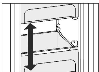
Diagram of a mechanical component with internal channels and an upward arrow, no text or symbols present5.5.8 VarioSpace
You can remove the shelves and drawers. This leaves more room for larger food items such as poultry, meat, large game and tall baked goods, which can be frozen whole before further preparation.
natural_image
Diagram of a mechanical assembly with two vertical arrows indicating direction (no text or symbols)▶ Each drawer can hold max. 25 kg of frozen food.
For 600 mm wide appliances:*
▶ The shelves can each be loaded with 35 kg of frozen food.*
For 700 mm wide appliances:*
▶ The shelves can each be loaded with 55 kg of frozen food.*
5.5.9 Ice cube tray\*
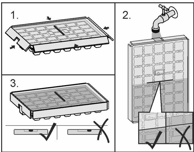
Fig. 47
When the water is frozen:
▶ Hold ice cube tray under hot water for a short time.
▶ Remove the lid.
▶ Gently turn the ends of the ice cube tray in opposite directions and release the cubes.
Dismantling the ice cube tray
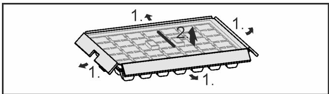
Fig. 48
▶ You can take the ice cube tray apart for cleaning.
5.5.10 IceMaker\*
The IceMaker produces ice cubes using the water container located in the refrigerator compartment. The water container can also be used to provide chilled drinking water. The IceMaker is located in the top drawer of the freezer on the left-hand side.
Make certain that the following conditions are met:
- The appliance is level.
- The appliance is connected.
- The freezer compartment is switched on.
- The water tank was cleaned with water and is filled.
Producing ice cubes\*
The production capacity depends on the freezer temperature. The lower the temperature, the more ice cubes can be produced in a specific period.
The ice cubes drop from the IceMaker into the drawer. When a certain filling level has been reached, no further ice cubes are produced. The IceMaker does not fill the drawer right up to the brim.
Distribute the ice cubes evenly in the drawer to increase the capacity.
If large quantities of ice cubes are needed, the complete IceMaker drawer can be exchanged for the adjacent drawer. When the drawer is closed, the IceMaker automatically recommences production.
Once the IceMaker has been switched on for the first time, it may take up to 24 hours until the first ice cubes are produced.
Note
When the appliance is used for the first time and if it has been out of use for a long time, particles may collect in the IceMaker and/or water conduit.
▶ Do not use or consume ice cubes that have been made 24 hours after the first ice cubes are made.
Filling the water tank\*

WARNING
Risk of poisoning!
The water quality must comply with the drinking water regulations of the respective country in which the appliance is operating (e.g. 98/83/EC, NSF 61).
▶ Only fill with drinking water.
The IceMaker is solely intended to produce ice cubes in quantities customary for household use and must be operated using water appropriate for this purpose.
▶ If the IceMaker is switched off or not used for a longer period of time, empty the water tank.
NOTICE
Risk of damage to the IceMaker!
Liquids containing sugar, such as soft drinks, fruit juices or similar, gum up the pump and therefore lead to total pump failure and, as a consequence, to damage to the IceMaker.
▶ Fill the water tank with cold drinking water only! Do not use liquids containing sugar, such as soft drinks, fruit juices or similar!
Note
Using filtered, decarbonised water ensures the best-tasting drinking water for your ice cubes.
This water quality can be achieved using a table water filter of the kind available in trade retail outlets.
▶ Always fill the water tank only with filtered, decarbonised drinking water.
The IceMaker is supplied with water from a water tank in the refrigerator compartment (see 1 Appliance at a glance). Before initial operation:
▶ clean the water tank thoroughly with water to remove any dust etc.
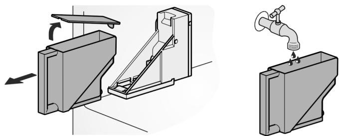
Fig. 49
▶ Pull the water tank forwards.
▶ Remove cover and fill tank with water.
▶ Replace the lid, put the filled water tank back into the holder and push it right to the back.
Note
The water reservoir has to be slid all the way into the bracket provided for the purpose in the refrigerator compartment!
Switch the IceMaker on.\*
▶ Press Menu.
▶ Press the navigation arrows until the IceMaker is displayed.
▶ Press the IceMaker symbol.
▶ Press ON.
▷ The IceMaker is switched on.

Note
▶ The IceMaker only makes ice cubes when the drawer is completely closed.
Flushing
Flushing function to rinse out the water pipe when used for the first time.
Note
The water pipe can only be rinsed out if the temperature is above 0 °C .
▶ Only use the Flushing option if the temperatures in the appliance are above 0 °C.
NOTICE
Blocked IceMaker and water outlet.
Risk of damage to the IceMaker and the drawer outlet.
▶ Put containers with a maximum height of 12 cm in the drawer under the IceMaker.
Ensure that the IceMaker drawer is empty.
▶ Do not place containers taller than 12 cm in the drawer under the IceMaker.
▶ Press Menu.
▶ Press the navigation arrows until the IceMaker is displayed.
▶ Press the IceMaker symbol.
▶ Press the navigation arrows until flushing is displayed.
▶ Press ON.
▷ Water pipes are rinsed and at the same time the ice cube tray is turned back to the cleaning position.
▶ Do not operate the screen during this procedure.
Flushing function terminated: The symbol appears.
▶ Press OK.
▶ Remove the drawer and the container.
▶ Clean the drawer and, if necessary, remove excess water from the drawer.
IceMaker holiday function\*
The IceMaker holiday function is suitable for short phases when no ice cubes are to be made, for example, when you are on holiday.
Switching the IceMaker holiday function on.
The IceMaker drawer must be emptied and pushed in.
▶ Press menu.
▶ Press the navigation arrows until the IceMaker is displayed.
▶ Press the IceMaker symbol.
▶ Press the navigation arrows until the IceMaker holiday function is displayed.
▶ Press ON.
▷ The ice cube tray moves to the cleaning position. The IceMaker switches to holiday function.
▷ The IceMaker holiday function symbol appears in the menu area.
▶ Remove the drawer.
▶ Clean the ice cube tray and drawer with a soft cleaning cloth and warm water. If necessary use a mild detergent. Then rinse out.
▶ Push the drawer in.
Switching the IceMaker holiday function off
NOTICE
Sickness caused by dirty ice compartment.
▶ After the IceMaker has been switched off for a long time, clean the ice cube tray.


NOTICE
Rinse agent residue in the ice compartment and drawer.
Nausea or irritation of the mucous membrane.
▶ Remove rinse agent residue: Discard the first three batches of ice cubes.
▶ Remove the drawer.
▶ Clean the ice cube tray and drawer with a soft cleaning cloth and warm water. If necessary use a mild detergent. Then rinse out.
▶ Push the drawer in.
▶ Press Menu.
▶ Press the navigation arrows until the IceMaker is displayed.
▶ Press the IceMaker symbol.
▶ Press OFF.
The ice cube tray moves to the operating position. The IceMaker switches on.
The IceMaker symbol appears in the menu field instead of the IceMaker holiday function symbol.

Switching off the IceMaker\*
If no ice cubes are required, the IceMaker can be switched off independently of the freezer compartment.
When the IceMaker is switched off, the drawer of the IceMaker can also be used for freezing and storing food.
▶ Cleaning the IceMaker (see 6.5 Cleaning the IceMaker*).
▶ Press Menu.
▶ Press the navigation arrows until the IceMaker is displayed.
▶ Press the IceMaker symbol.
▶ Press OFF.
▷ The IceMaker is switched off.
▶ If necessary, food can now be frozen in the drawer up to a maximum height of 12 cm.

6 Maintenance
6.1 Change the FreshAir filter.
The FreshAir filter guarantees optimum air quality. It should be changed every 12 months. When the timer is set a message on the display prompts you to change it. The FreshAir filter can be ordered from the specialist dealer.
Change FreshAir filter is displayed.
▶ Press the change FreshAir filter symbol
▷ The display switches to the home screen.
The message can be displayed again by pressing on the menu field until the filter has been changed and confirmed. (see 8 Messages).

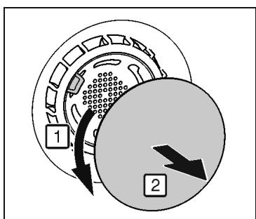
Fig. 50
▶ Remove cover.
natural_image
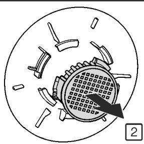
Diagram of a mechanical component with multiple slots and a central circular feature, no text or symbols present.Fig. 51
▶ Remove the FreshAir filter.
▶ Insert the new filter in the reverse order.
▶ Ensure that the filter clicks into place.
▶ Replace the cover again.
- Remove the FreshAir filter.
- Insert the new filter in the reverse order.
- Ensure that the filter clicks into place.
- Replace the cover again.
Confirming the filter change
▶ Press menu.
▶ Press the navigation arrows until the FreshAir filter is displayed.
▶ Press the FreshAir filter symbol.
▶ Press the navigation arrows until change FreshAir filter is displayed.
▶ Press RESET.
▷ The timer is reset. The change interval starts all over again.
Turning the timer off
If a new FreshAir filter is not inserted the timer can be turned off
▶ Press menu.
▶ Press the navigation arrows until the FreshAir filter is displayed.
▶ Press the FreshAir filter symbol.
▶ Press OFF.
▷ The timer is turned off.

6.2 Defrosting with NoFrost
The NoFrost system automatically defrosts the appliance.
Refrigerator compartment:
The defrosted water is evaporated by the heat of the compressor. Water drops or a thin layer of frost or ice can form on the back wall; this is a completely normal part of the machine's function.
▶ Regularly clean the drain opening to allow the water to flow away (see 6.4 Cleaning the appliance).
Freezer compartment:
The moisture condenses on the evaporator, is periodically defrosted and evaporates.
▶ The appliance does not have to be manually defrosted.
6.3 Cleaning the ventilation grid
The ventilation grid ensures that the appliance works properly due to optimum aeration and ventilation.
▶ Clean the ventilation grid regularly with a vacuum cleaner.
▶ Remove stubborn stains with a soft cloth.
When the timer is set a message on the display prompts you to clean it. The clean ventilation grid symbol appears on the screen.

▶ Press the clean ventilation grid symbol.
▷ The display switches to the home screen.
The message can be displayed again by pressing the menu field until it has been cleaned and this has been confirmed. (see 8 Messages).
Confirming that the ventilation grid has been cleaned
▶ Press menu.
▶ Press the navigation arrows until the ventilation grid is displayed.
▶ Press the ventilation grid symbol.
▶ Press the navigation arrows until clean ventilation grid is displayed.
▶ Press RESET.
▷ The timer is reset. The cleaning interval starts all over again.


Turning the timer off
If the reminder function is to be switched off the timer can be turned off.
▶ Press menu.
▶ Press the navigation arrows until the ventilation grid is displayed.
▶ Press the ventilation grid symbol.
▶ Press OFF.
▷ The timer is turned off.

6.4 Cleaning the appliance
Clean the appliance regularly.

WARNING
Risk of injury and damage as a result of hot steam! Hot steam can lead to burns and can damage the surfaces.
▶ Do not use any steam cleaners!
NOTICE
Incorrect cleaning damages the appliance!
▶ Do not use cleaning agents in concentrated form.
▶ Do not use any scouring or abrasive sponges or steel wool.
▶ Do not use any sharp or abrasive cleaning agents, nor any that contain sand, chloride or acid.
▶ Do not use chemical solvents.
▶ Do not damage or remove the type plate on the inside of the appliance. It is important for the customer service.
▶ Do not pull off, bend or damage cables or other components.
▶ Do not allow any cleaning water to enter the drain channel, ventilation grille or electrical parts.
▶ Please use soft cleaning cloths and a universal pH-neutral cleaning agent.
▶ Please use cleaning and care products suitable for contact with foodstuffs in the appliance interior.
▶ Empty appliance.
▶ Pull out the power plug.

▶ Clean plastic outer and inner surfaces with lukewarm water and a little washing-up liquid.
▶ Only use a soft clean cloth to wipe side walls with a paint finish. In the case of heavy soiling, use lukewarm water with neutral cleaning agent.*
NOTICE
Risk of damage from stainless steel care products!
The stainless steel doors and stainless steel side panels are treated with a premium surface finish.
Stainless steel care products attack these surfaces.

▶ Only use a soft, clean cloth to wipe down finished door and side panel surfaces and painted door and side panel surfaces. To remove heavy dirt, use a little water or neutral detergent. Alternatively, you can use a micro-fibre cloth.
Do not treat the lettering on the painted door surfaces with harsh, abrasive agents. Wipe off any dirt with a soft cloth and some water or neutral cleaner.*
▶ Clean drain hole: Remove deposits with a narrow instrument, e.g. a cotton bud.
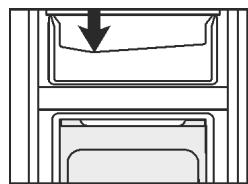
natural_image
Diagram showing a downward arrow pointing to a rectangular object, with no text or symbols present.▶ Empty water collect tray: remove water tank. Carefully unlatch tray at front and then remove from below.*
▶ Clean the water container by hand using lukewarm water and a small amount of dish washing liquid.*
▶ The water container and cover are dishwasher safe up to max. 60° *
natural_image
Diagram of a mechanical device with directional arrows indicating motion (no text or symbols)▶ Most of the parts can be dismantled for cleaning: see the relevant chapter.
▶ Clean drawers by hand with lukewarm water and a little washing up liquid.
▶ All the other fittings can be put in the dishwasher.
▶ Only use a damp cloth to clean the telescopic rails. The grease in the runners is for lubrication purposes and must not be removed.*
Note
▶ Clean water reservoir when not in use for more than 24 h.*
After cleaning:
▶ Wipe dry the appliance and items of equipment.
▶ Connect the appliance and switch it on again.
▶ Switch on SuperFrost (see 5.5.5 SuperFrost). When the temperature is sufficiently cold:
▶ Put the food back inside.
6.5 Cleaning the IceMaker\*
The IceMaker drawer must be emptied and pushed in. The IceMaker must be switched on.
▶ Press Menu.
▶ Press the navigation arrows until the IceMaker is displayed.
▶ Press the IceMaker symbol.
▶ Press the navigation arrow until the cleaning position is displayed.
▶ Press ON.
▷ The ice cube tray moves to the cleaning position. The screen cannot be used during this process.
▷ OFF appears: The rotary movement stops and the IceMaker switches off for cleaning.
▶ Remove the drawer.
▶ Clean the ice cube tray and drawer with a soft cleaning cloth and warm water. If necessary use a mild detergent. Then rinse out.
▶ Push the drawer in.
▶ Press OFF.
▷ The ice cube tray moves to the operating position.
NOTICE
Rinse agent residue in the ice compartment and drawer. Nausea or irritation of the mucous membrane.
▶ Remove rinse agent residue: Discard the first three batches of ice cubes.
▶ Leave the IceMaker switched on.
-or-


▶ Switch the IceMaker off (see 5 Control)
6.6 Customer service
First check whether you can rectify the fault yourself (see 7 Malfunctions). If you cannot rectify the problem, contact Customer Services. You can find the address in the enclosed Customer Service Directory.*

WARNING
Unprofessional repair! Injuries.
▶ Have any repairs and action - not expressly specified - on the appliance and mains cable carried out by service personnel only. (see 6 Maintenance)
A damaged mains cable may only be replaced by the manufacturer, the manufacturer's Customer Service or a similarly qualified person.
▶ In the case of appliances with an IEC connector, the change may be made by the customer.
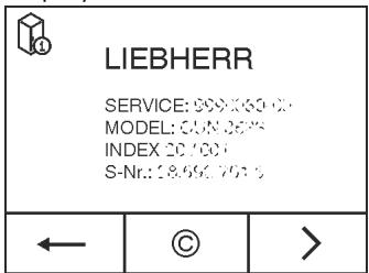
Call up the appliance designation (model and index), service no. (service), serial no. (s-no.) as well as the expanded functions on the screen:
▶ Press menu.
▶ Note down the appliance information.
▶ To return to the home screen press the Back symbol.
▶ Press the navigation arrows until the appliance information symbol is displayed.
▶ Press the appliance information symbol.
▷ The appliance information is displayed.
▶ To access the customer menu, press it until the key symbol appears.
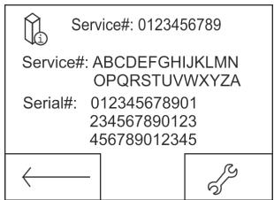
▶ Enter the numerical code 151 to select the customer menu.
Customer menu
The following functions can be called up in the customer menu:
- Self diagnostics
The appliance carries out self diagnostics and checks all electrical components.
- RESET
The appliance is reset to the factory settings.
- Manual defrosting
Manual defrosting starts.
- Water supply time
This function is active for appliances with an ice cube maker. The size of the ice cubes is determined by the water supply time.*
▶ Close the door.
▶ Contact customer service and give them the required appliance information.
▷ This will help us to provide you with a faster, more accurate service.
▶ Follow any further instructions given by Customer Services.
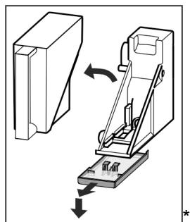
Alternatively you can read off the appliance information from the model plate:
The model plate is inside the appliance on the left-hand side.

Fig. 52 *
(1) Appliance description
(3) Serial no.
(2) Service no.
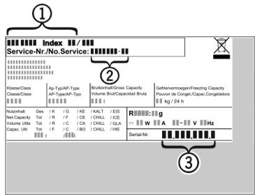
Fig. 53 *
(1) Appliance description
(3) Serial no.
(2) Service no.
Licence agreements:
Licences used can be viewed at ©.
▶ Press ©.
6.7 Energy efficiency class lighting\*
| Lighting | |
| Energy efficiency class1 | Light source |
| This product contains an energy efficiency class G light source | LED |
1 The appliance may contain light sources with different energy efficiency classes. The lowest energy efficiency class is indicated.
7 Malfunctions
Your appliance is designed and manufactured for a long life span and reliable operation. If a malfunction nonetheless occurs during operation, check whether it is due to a handling error. In this case you will have to be charged for the costs incurred, even during the warranty period. You may be able to rectify the following faults yourself:
Appliance does not work.
→ The appliance is not switched on.
▶ Switching on the appliance.
→ The power plug is not properly inserted in the wall socket.
▶ Check power plug.
→ The fuse of the wall socket is not in order.
▶ Check fuse.
→ The appliance plug does not fit the appliance properly.
▶ Check the appliance plug.
The compressor runs for a long time.
→ The compressor switches to a low speed when little cold is needed. Although the running time is increased as a result, energy is saved.
This is normal in energy-saving models.
→ SuperFrost is activated.
▶ The compressor runs for longer in order to rapidly cool the food. This is normal.
→ SuperCool is activated.
▶ The compressor runs for longer in order to rapidly cool the food. This is normal.
Excessive noise.
→ Due to the various speed steps, speed-regulated* compressors can generate different running noises.
▶ The sound is normal.
A bubbling and gurgling noise.
→ This noise comes from the refrigerant flowing in the refrigeration circuit.
▶ The sound is normal.
A quiet clicking noise.
→ The noise is produced whenever the refrigeration unit (motor) automatically switches on or off.
▶ The sound is normal.
A hum. It is briefly a little louder when the refrigeration unit (the motor) switches on.
→ The refrigeration increases automatically when the SuperFrost, function is activated, fresh food has just been placed in the appliance or the door has been left open for a while.
▶ The sound is normal.
→ The refrigeration increases automatically when the SuperCool function is activated, fresh food has just been placed in the appliance or the door has been left open for a while.
▶ The sound is normal.
→ The ambient temperature is too high.
▶ Solution: (see 1.2 Appliance range of use)
A low hum.
→ The sound is produced by air flow noise of the fan.
▶ The sound is normal.
Vibration noises
→ The appliance is not standing firmly on the floor. As a result objects and adjacent units start to vibrate when the refrigerator is running.
▶ Align the appliance using the adjustable feet.
▶ Keep bottles and jars apart.
Hum of the water tank pump.\*
→ When water is pumped out of the water reservoir, a brief hum of the pump can be heard.
▶ The sound is normal.
The DEMO symbol appears on the screen. In addition some time elapses.
→ DEMO mode is activated.
▶ OFF Press.
DEMO is displayed in the top right corner of the screen.
→ DEMO mode is activated.
▶ Unplug the appliance.
▶ Plug the appliance in again.
▷ The DEMO symbol appears on the screen. In addition some time elapses.
▶ OFF Press.
The outer surfaces of the appliance are warm\*.
→ The heat of the refrigeration circuit is used to prevent condensate from forming.
This is normal.
The IceMaker cannot be switched on. \*
→ The appliance and therefore the IceMaker are not connected.
▶ Connect the appliance to the mains (see 4 Putting into operation).
The IceMaker does not make any ice cubes.\*
→ The IceMaker is not switched on.
▶ Switch on the IceMaker.
→ The drawer of the IceMaker is not properly closed.
▶ Close the drawer properly.
→ The water tank is not correctly inserted.
▶ Insert the water tank.
→ There is not enough water in the water tank.
▶ Filling the water tank.
Functions in the IceMaker submenu do not start.\*
→ Ice cube tray rotates.
▶ Try again after 1 minute.
The temperature is not cold enough.
→ The door of the appliance is not properly closed.
▶ Close the door of the appliance.
→ Insufficient ventilation.
▶ Keep ventilation grille clear, and clean it.
→ The ambient temperature is too high.
▶ Solution: (see 1.2 Appliance range of use).
→ The appliance was opened too frequently or for too long.
▶ Wait to see whether the appliance reaches the required temperature by itself. If not, please contact the after sales service (see 6 Maintenance).
→ Too much fresh food was placed inside without SuperFrost.
▶ Solution: (see 5.5.5 SuperFrost)
→ The temperature is incorrectly set.
▶ Set the temperature to a colder setting and check after 24 hours.
→ The appliance is too close to a source of heat (stove, heater etc).
▶ Change the position of the appliance or the source of heat.
The internal light does not come on.
→ The appliance is not switched on.
▶ Switch the appliance on.
→ The door was open for longer than 15 minutes.
The internal light switches itself off automatically after about 15 minutes if the door is open.
→ The LED illumination is faulty or the cover is damaged:

WARNING
Risk of injury due to electric shock!
There are live electrical parts under the cover.
▶ Only ever have the inside LED light replaced or repaired by customer service or trained personnel.

WARNING
Risk of injury from LED bulb!
The light intensity of the LED light corresponds to hazard group RG 2.
If the cover is defective:
▶ Do not look directly into the light from close range. It cause injury to the eyes.
The door seal is defective or needs to be replaced for another reason.
→ The door seal can be replaced. It can be replaced without the need for special tools.
▶ Contact Customer Service (see 6 Maintenance):
The unit has iced up or condensation has formed.
→ The door seal may have also slipped out of its groove.
▶ Check to ensure that the door seal is seated properly in the groove.
8 Messages
Error messages and reminders are displayed by an audible signal and a message on the screen. The audible signal gets louder and louder when error messages appear. It only stops when the message is confirmed. Highest priority messages are displayed first if several occur at the same time. Each message must be cleared separately.

The message stays in the menu field as long as it is active or the fault is not eliminated.
Note
Details on the message can be displayed again via the menu field.
▶ Press menu.
▶ Press the message symbol. ⚠️
The display switches to the next message when you press one. After the last active message the display switches to the home screen.
Door alarm
An audible warning sounds if the door is open for longer than 60 seconds. The door alarm symbol appears on the display. The audible warning stops automatically when the door is closed.
The audible warning can be switched off when the door is open. The audible alarm is switched off while the door is open.
▶ Press the door alarm symbol.
▷ The door alarm stops.
▷ The display switches to the home screen.
▶ Close the door.
Temperature alarm
An audible signal sounds if the temperature is not cold enough. The temperature alarm symbol appears on the display.
The temperature had risen too high during the last few hours or days. When the fault is eliminated the appliance continues to work at the last temperature setting.
The reason for too high a temperature may be:
- hot, fresh food was inserted
- too much warm room air flowed in when rearranging and removing food
- the power was cut off for a while
- the appliance is faulty
▶ Open the door.
▶ Press the temperature alarm symbol.
The audible signal stops. The warmest temperature reached during the malfunction is displayed on the screen.
▶ Press the screen or wait for 30 seconds.
The display switches to the home screen. Arrows and the temperature alarm symbol appear in the relevant temperature field ⬇ ⬇. In addition the messages symbol is displayed in the menu field ⚠.
▶ Check the food for quality. Do not consume spoiled food. Do not re-freeze defrosted food,
▶ Close the door.
▷ The symbols are greyed out when the target temperature is reached.
If the alarm status persists or the temperature cannot be reset independently:
(see 7 Malfunctions).
Power cut
An audible warning sounds. The power cut symbol appears on the display.
The temperature had risen too high over the last few hours or days due to a power cut or power interruption. When the power is restored the appliance continues to work at the last temperature setting. Activated reminders are retained.
▶ Open the door.
▶ Press the power cut symbol.
The audible signal stops. The warmest temperature reached in the freezer compartment during the power cut is displayed on the screen.
▶ Press the screen or wait for 30 seconds.
The display switches to the home screen. Arrows and the symbol temperature alarm appear in the relevant temperature field ⬇. The messages symbol is also shown in the menu field ⚠.
▶ Check the food for quality. Do not consume spoiled food. Do not re-freeze defrosted food,
▶ Close the door.
▷ The symbols are greyed out when the target temperature is reached.
Appliance faults
An audible warning sounds. The appliance fault symbol appears on the display with the relevant error code.
An appliance component indicates a fault.
▶ Open the door.
▶ Note down the fault code.
▶ Press the appliance fault symbol.
The audible signal stops. The display switches to the home screen.
▶ Close the door.
▶ Contact Customer Services (see 6 Maintenance).
If the fault related to a specific temperature zone, the appliance fault symbol is displayed instead of the temperature in the zone's temperature field.
Fill the water tank\*
An audible warning sounds. The water tank symbol appears on the display.

There is not enough water in the water tank.
▶ Fill the water tank.
▶ When the water tank is full and a message persists, check if the float is stuck.
▶ If necessary, empty the water and move the float with a thin instrument, e.g. a cotton bud.
▶ If you still see the message after filling the water tank, contact Customer Services (see 6 Maintenance).
Other messages

FreshAirChange filter (see 6 Maintenance)

Clean the ventilation grille (see 6 Maintenance)
Open, close IceMaker drawer*
9 Decommissioning
9.1 Switching the appliance off
Note
If the appliance or the freezer or fridge compartment cannot be switched off the child safety device has been switched on.
▶ Switch the child safety device off (see 5.2.2 Switching the child safety device off).
9.1.1 Switch off the appliance from the menu
The whole appliance is switched off. The screen goes black.
▶ Press menu.
▶ Press the navigation arrows until the standby symbol is displayed.
▶ Press OK.
▷ The standby symbol flashes on the whole screen. The whole appliance is switched off.
▷ After 10 minutes the standby symbol goes out.
9.1.2 Switching the appliance off via the freezer compartment field.
The fridge compartment is automatically turned off when the freezer compartment is turned off. The screen remains on.
▶ Press the freezer compartment field.
▶ Press plus.
The plus symbol is greyed out if it is pressed again after selecting the hottest temperature. The standby symbol is displayed on the screen.
▶ Press OK.
▷ The standby symbol is displayed in all temperature fields.
▷ The freezer and fridge compartments are switched off.
9.1.3 Switching the fridge compartment off
If necessary, the fridge compartment can be switched off separately.

CAUTION
Danger of poisoning.
Not cooling the water tank spoils the water in the tank.
▶ Switch the IceMaker off (see 5 Control).
▶ Press the fridge compartment field.
▶ Press plus.
The plus symbol is greyed out if it is pressed again after selecting the hottest temperature. The standby symbol is displayed on the screen.
▶ Press OK.
▷ The standby symbol is displayed in the fridge compartment field.
▷ The fridge compartment is switched off.
9.2 Taking the appliance out of service
▶ Empty the appliance.
▶ Put the IceMaker in the cleaning position (see 6 Maintenance) *
▶ Switch off the appliance (see 9 Decommissioning)
▶ Remove mains connector.
▶ Remove appliance connector if required: Remove and move from left to right at the same time.
▶ Clean the appliance (see 6.4 Cleaning the appliance).
▶ Leave the door open to prevent odour.
10 Disposal
10.1 Preparing appliance for disposal

Li-Ion
Liebherr uses batteries in some of its appliances. In the EU, for environmental reasons, legislation obliges the end user to remove these batteries before disposing of old appliances. If your appliance contains batteries, a corresponding notice is attached.
Lamps
If you can remove the lamps yourself without destroying them, also remove these before disposal.
▶ Take the appliance out of operation. (see 9.2 Taking the appliance out of service)
▶ Appliances with batteries: remove the batteries. For description, see Maintenance chapter.
▶ If possible: remove lamps without destroying them.
10.2 Disposing of the appliance in an environmentally friendly manner
The appliance still contains valuable materials and must be disposed of separately from unsorted municipal waste.

Li-Ion
LI-Ion
Dispose of batteries separately from the old appliance. To do this, you can return the batteries free of charge to retailers as well as recycling centres and collection centres for recyclable materials.
Lamps
Dispose of removed lamps via the respective collection systems.
For Germany:*
You can dispose of the appliance free of charge via the class 1 collection containers at the local recycling and recyclable material collection centres. When purchasing a new fridge/freezer, if the sales area >400 m ^2 , retailers will also take back the old appliance free of charge.*

WARNING
Leaking coolant and oil!
Fire. The coolant contained in the appliance is eco-friendly, but also flammable. The oil contained in the appliance is flammable. Escaping coolant and oil can ignite if the concentration is high enough and in contact with an external heat source.
▶ Do not damage the pipelines of the coolant circuit and the compressor.
▶ Transport the appliance without damaging it.
▶ Dispose of batteries, lamps and the appliance according to the above specifications.