
FDv 4613 - Combined refrigerator LIEBHERR - Free user manual and instructions
Find the device manual for free FDv 4613 LIEBHERR in PDF.
| Product type | Combined refrigerator (dynamic freezer) |
| Brand | Liebherr |
| Model | FDv 4613 |
| Temperature range | -10 °C to -25 °C |
| Display | Digital (actual value) |
| Temperature alarm | Visual and audible (triggered if deviation > 5 °C) |
| Door alarm | Visual and audible (after 10 minutes open) |
| Defrost | Automatic hot gas |
| Interior lighting | LED (side) |
| Ventilation | Evaporator and condenser fan |
| Refrigerant | R290 (propane) |
| Power supply | 220-240 V, 50/60 Hz |
| Evaporation tray heater power | Approximately 65 W |
| LED lighting power | Approximately 19.5 W |
| Condenser fan power | Approximately 60 W (1300 rpm) |
| Evaporator fan power | Approximately 13 W (1550 rpm) |
| Solenoid valve | Approximately 4.5 W (2/1 way) |
| Door | Glazed, reversible (requires technical intervention) |
| Sensors | Air sensor and evaporator sensor |
| Maintenance | Cleaning the condenser, replacing the door gasket |
Frequently Asked Questions - FDv 4613 LIEBHERR
User questions about FDv 4613 LIEBHERR
0 question about this device. Answer the ones you know or ask your own.
Ask a new question about this device
Download the instructions for your Combined refrigerator in PDF format for free! Find your manual FDv 4613 - LIEBHERR and take your electronic device back in hand. On this page are published all the documents necessary for the use of your device. FDv 4613 by LIEBHERR.
USER MANUAL FDv 4613 LIEBHERR
Appliance Documentation
FDv 4613 from Index 40I
Fv 3613 from Index 40I
Freezer for presentation of goods, ventilated
FDv 4613
Fv 3613
Contents
1.0 Operating and control elements 3
1.1 Significance of the control elements 3
2.0 Functions at a glance 4
3.0 Description of appliance 5
3.1 Sensor positions, schematic diagrams 5
4.0 Main components and their functions 6
4.1 Electrical components and functions 6
4.2 Refrigeration components and functions 9
4.2.1 Components: 9
4.2.2 Function principle 9
4.2.3 Defrost water evaporation channel and solenoid valve 11
5.0 Assembly instructions/Parts replacement 12
5.1 Electronics 12
5.2 Reed switch 13
5.3 Sensors 14
5.4 Evaporator fan 18
5.5 Defrost water collection pan with heater 19
5.6 LED lighting 20
5.7 Transformer 21
5.8 Condenser fan 21
5.9 Exchange of seal 22
5.10 Door exchange 23
5.10.1 Changing over the door hinges 28
6.0 Technical Data 31
7.0 Messages and error codes 32
7.1 Testing the evaporator temperature 32
7.2 Calling up the minimum and maximum internal temperature 32
7.3 First level parameters (without password entry) 33
7.4 Error codes 34
7.5 Status messages 34
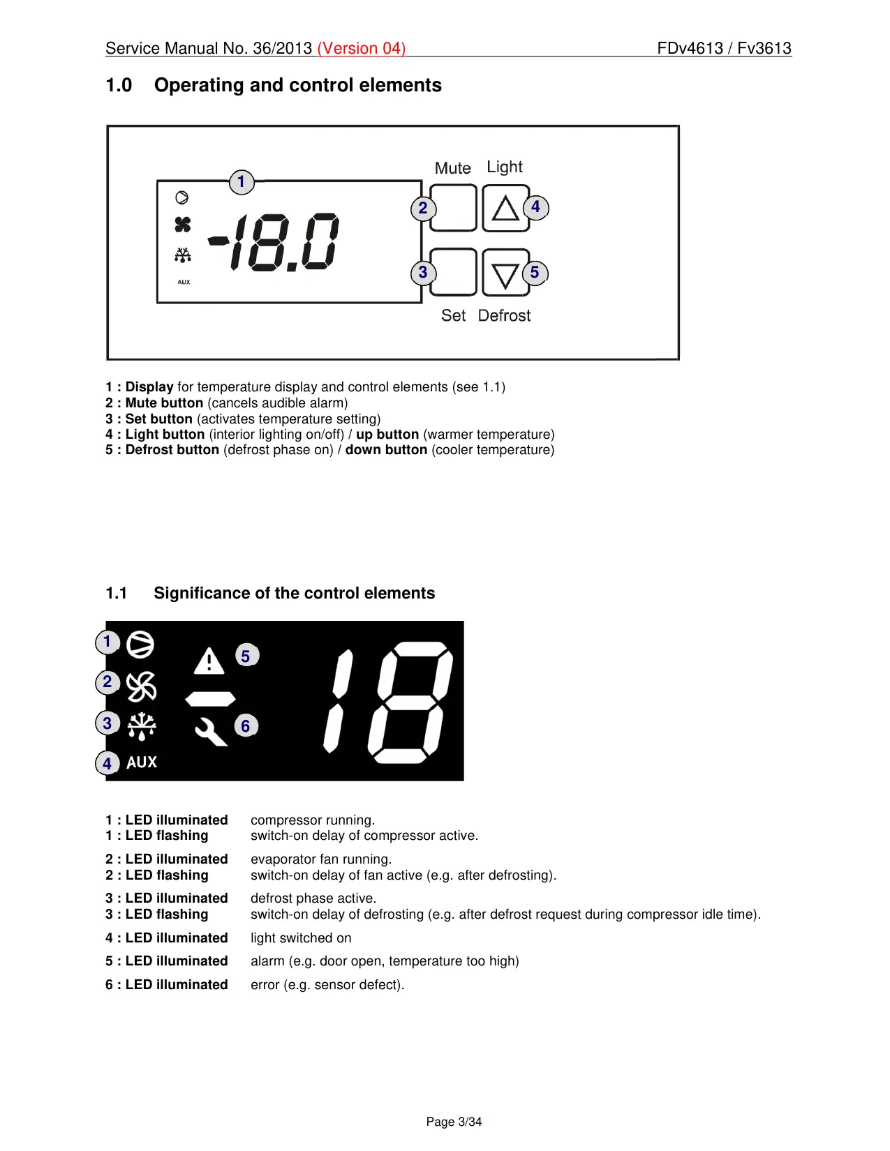
1.0 Operating and control elements
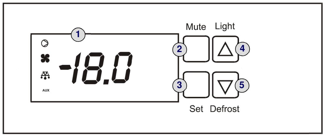
1 : Display for temperature display and control elements (see 1.1)
2: Mute button (cancels audible alarm)
3: Set button (activates temperature setting)
4: Light button (interior lighting on/off) / up button (warmer temperature)
5: Defrost button (defrost phase on) / down button (cooler temperature)
1.1 Significance of the control elements
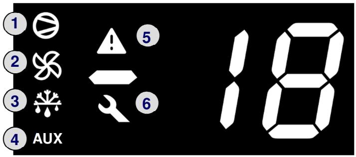
1:LED illuminated compressor running.
1:LED flashing switch-on delay of compressor active.
2:LED illuminated evaporator fan running.
2:LED flashing switch-on delay of fan active (e.g. after defrosting).
3 : LED illuminated defrost phase active.
3 : LED flashing switch-on delay of defrosting (e.g. after defrost request during compressor idle time).
4:LED illuminated light switched on
5:LED illuminated alarm (e.g. door open, temperature too high)
6:LED illuminated error (e.g.sensor defect).
2.0 Functions at a glance
| Control: | Electronics |
| Temperature display: | Digital (actual value) |
| Temperature range: | -10°C to -25°C |
| Temperature alarm: | Visual and audible |
| Door alarm: | Visual and audible |
| Volt-free contact: | Not featured |
| HACCP function: | Not featured |
| Interface: | Not featured |
| Fan: | Featured |
| Defrosting: | Automatic |
| Interior light: | Featured |
| Service menu: | Not featured |
| Compressor: | Standard |
| Solenoid valve refrigeration circuit: | Featured (for defrosting) |
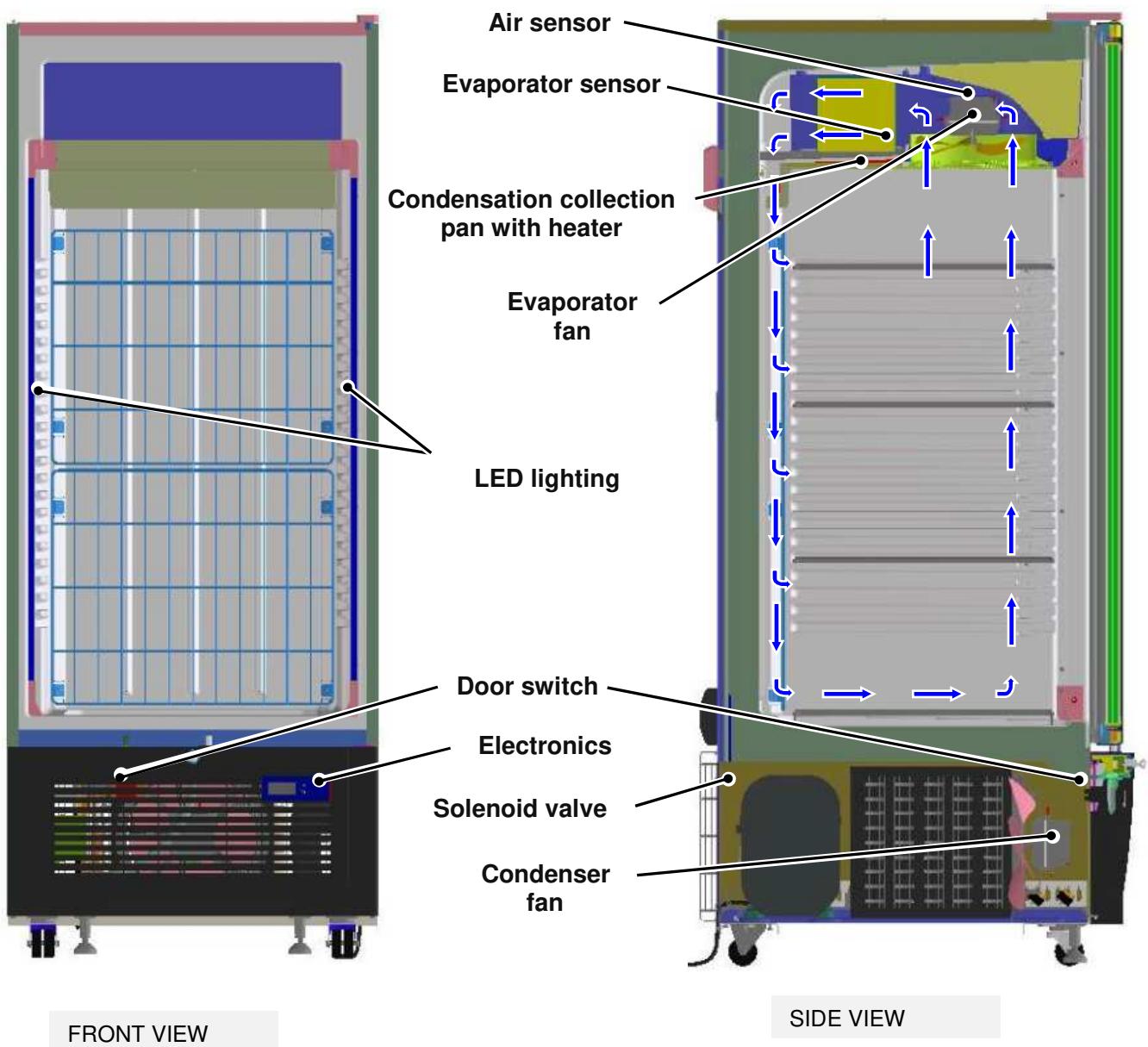
3.0 Description of appliance
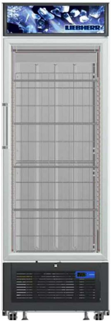
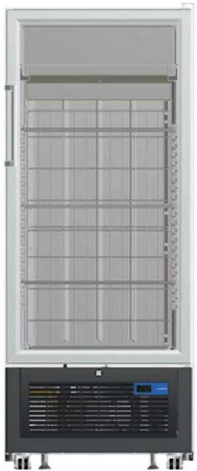
The models F(D)v 3613/4613 are dynamically cooled freezers with glass doors and LED lighting. In some versions, the appliances are fitted with castors as a series standard.
A fan draws air from the interior through the evaporator and blows cold air back into the interior.
Temperature control is electronic.
Defrosting is via hot gas.
3.1 Sensor positions, schematic diagrams
4.0 Main components and their functions
4.1 Electrical components and functions
| Electronics | |
| Type: | Electronic microprocessor control unit from CAREL with digital display |
| Components: | Electronics housing |
| Setting range: | -10°C to -25°C |
| Display range: | -50°C to 150°C |
| Functions | |
| Temperature alarm: | When: As soon as the value fails to reach or exceeds the target value by 5°C (41°F) |
| Audible: Intermittent beep (suppressed during start-up) | |
| Visual: The alarm symbol is illuminated and the display shows either code HI (too warm) or LO (too cold). | |
| To avoid unnecessary warnings (e.g. door opening), the threshold value must fail to be reached or be exceeded for at least 15 minutes. | |
| Door alarm: | When: Door open for longer than 10 minutes |
| Audible: Intermittent beep | |
| Visual: The alarm symbol is illuminated and the display shows code "dor". | |
| If the door is open, the alarm symbol flashes immediately and the temperature display also flashes – the actual alarm is not activated until the above mentioned time has elapsed. | |
| Defrosting: | |
| Activation: - Automatic, 25 minutes after every new start-up | |
| - Automatic, every 6 hours. | |
| - Manual, when the defrost/down button is pressed for 5 seconds. | |
| Function: Hot gas defrosting (see chap. 4.2.2.2.). | |
| The defrost water is collected in the electrically heated collection pan and fed into the defrost water evaporation channel through a hose. During the next cooling phase this channel is heated by hot gas and the water evaporates. | |
| Termination: The defrosting phase is generally terminated thermally14°C(57.2°F). | |
| If no thermal termination occurs, the defrosting phase is ended after 25 minutes (see chap. 7.5). | |
| After 2 minutes of drip-off time plus another 4 minutes (due to minimum compressor off time c2 = 6), the compressor will start up again. | |
| The evaporator fan will start up again 5 minutes after the compressor start. | |
| Display: The defrost symbol is illuminated during the defrost phase. | |
| During the defrost phase, the value last displayed prior to the start of defrosting is recorded. The display is reactivated as soon as the target value is once more achieved after the end of the defrost phase, but in all cases within the alarm delay time. | |
| (The temperature alarm is deactivated for one hour after the end of the phase). | |
| Special feature: In the event of mains power failure, all times are reset to 0! i.e. the appliance functions normally once the power supply has been restored and will initiate the next defrost phase according to the programmed interval. | |
| Sensors | |||||
| Air sensor: | Position: | On the left next to the fan, clipped into the fan holder panel. | |||
| Function: | - Generates the display value. The “Update Display” parameter has been set to the highest ...value -> reaction is therefore very muted! | ||||
| - Switches the compressor on/off. Hysteresis amounts to -2°C. (E.g.: at a target value of -18°C(0°F) the compressor will switch on at -16°C(3.6°F) and off at-18°C (0°F). | |||||
| In the event of an error (interruption or short circuit) the error symbol will be illuminated and the display will show the code E0. -> The appliance will function in emergency mode: 12 minutes on / 15 minutes off | |||||
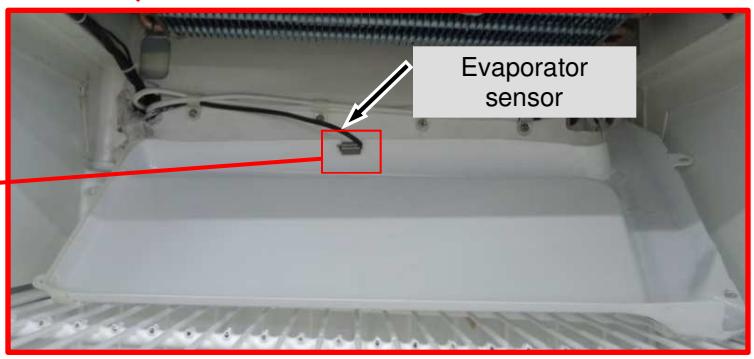
| Evaporator sensor: | Position: | On the below of the evaporator, clip on collection pan. | |||
| Function: | - Terminates the defrosting phase at 14°C(57.2°F) In the event of an error (interruption or short circuit) the error symbol is illuminated and the display shows the code E1. -> The appliance will continue to work in normal mode – defrosting will be ended after the time limit has expired | ||||
| Switches | |||||
| Door switch: | Position: | In the appliance plinth. | |||
| Type: | Reed Switch | ||||
| Contact type: | Make contact with magnet mounted on door | ||||
| Function: | The door operates with a reed switch in the plinth panel. This operates make contact reed switch and the magnet on door. | ||||
| Switching signal when: | |||||
| Door closed: | Door alarm | OFF | |||
| Evaporator fan | ON | ||||
| Door open: | Door alarm | ON | |||
| Evaporator fan | OFF | ||||
| Light button: | Position: | On the control unit. | |||
| Function: | Switches the display and interior light continuously on or off (must be pressed for about 1 second). | ||||
| Consumers / loads | |||||
| Door heater: | Position: | In the door frame and on the glass panel | |||
| Function: | Continuously on – prevents condensate formation. | ||||
| Display lighting(FDv 4613): | Position: | In the display | |||
| Function: | Back-lights the lettering. | ||||
| LED lighting: | Position: | On the left and right side walls | |||
| Function: | Lights the interior and the goods. | ||||
| Evaporator fan: | Position: | In front of the evaporator, on the ceiling of the inner liner. | |||
| Function: | Draws out the air and blows it back into the interior through the compressor. | ||||
| Special feature: | Compressor run ,fan run. Compressor off, fan off.Exception: When door is open or during defrosting phase!- If the door stays open long enough for the alarm to sound, the fan will start up again.- After termination of the defrost phase, the fan will restart after a time delay. | ||||
| Condenser fan: | Position: | In front of the condenser | |||
| Function: | Cools the condenser and runs parallel to the compressor | ||||
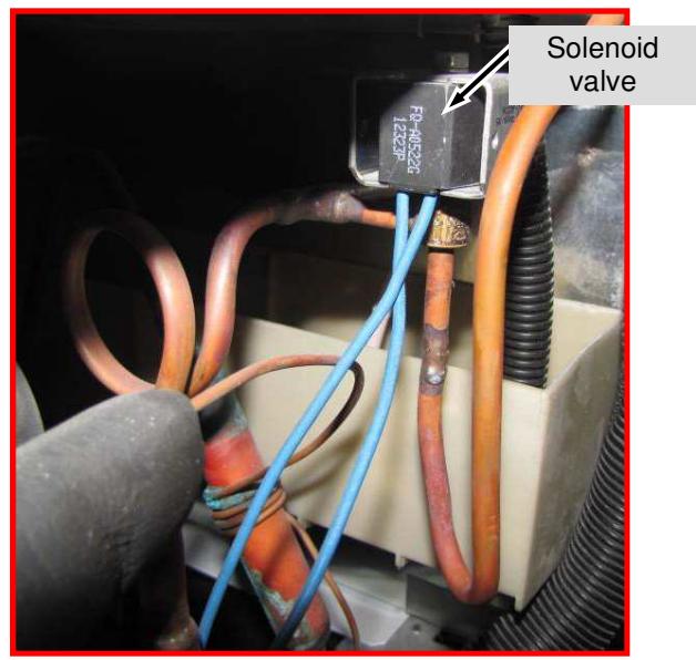
| Solenoid valve: | Position: | Behind the compressor | |||
| Function: | Opens a bypass for defrosting, feeding the hot gas directly into the evaporator | ||||
| Type: | 2/1 valve | ||||
| Compressor: | Function: | On: Air sensor switch-on value.Off: Air sensor switch-off value.Special feature: The compressor has a restart delay of 6 minutes.Should the compressor be actuated during this time, the compressor symbol in the display will flash (compressor start request). As soon as the compressor is running, the LED will be illuminated.Type: | Standard | ||
| Heater for the defrostCollection pan: | Position: | Glued to the underside of the collection pan. | |||
| Function: | Heats the pan during the defrost phase, in order to allow the defrost water to run off. | ||||
4.2 Refrigeration components and functions
4.2.1 Components:
| Compressor: | Standard | |
| Solenoid valve: | 2/1 valve | |
| Evaporator: | Construction: | Lamellar evaporator. |
| Type of mounting: | On the ceiling | |
| Injection point: | Back left | |
| Flow sequence: | From bottom to top | |
| Frame heater: | Position: | Foamed in in the housing frame section. |
| Type: | Hot gas | |
| Defrost water evaporation heater: | Position: | In the defrost water evaporation channel |
| Type: | Hot gas | |
| Condenser: | Type of appliance: | Lamellar condenser |
| Type of mounting: | In the appliance plinth | |
| Refrigerant: | R290 | |
4.2.2 Function principle
4.2.2.1 Refrigeration
The solenoid valve is closed. The refrigerant runs through the customary circuit.
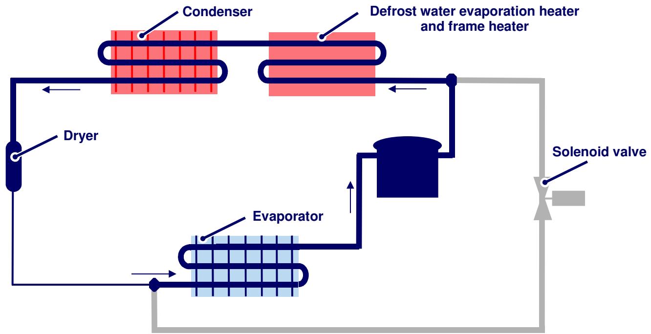
4.2.2.2 Hot gas defrosting
Defrosting of the evaporator is by hot gas. Before the defrosting phase, the compressor must be running. If there is a defrost request during the compressor idle time, the appliance will cool normally for a minute before the solenoid valve is actuated. This is to ensure that hot gas is available.
When the defrost phase starts, the solenoid valve opens and hot gas flows through the bypass into the compressor. The refrigerant is then cooled down briefly by the ice-encrusted evaporator and is thus liquefied, then subsequently evaporated in the evaporator by the heat of the latter. The gaseous refrigerant which is heated by the dissipated heat from the compressor is then pumped through the circuit.
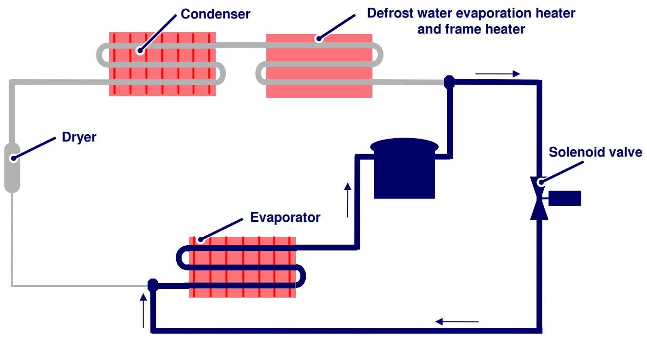
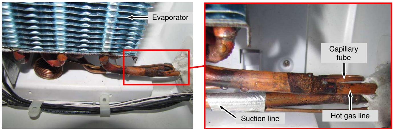
Fig. 4.2.2.2 / 1
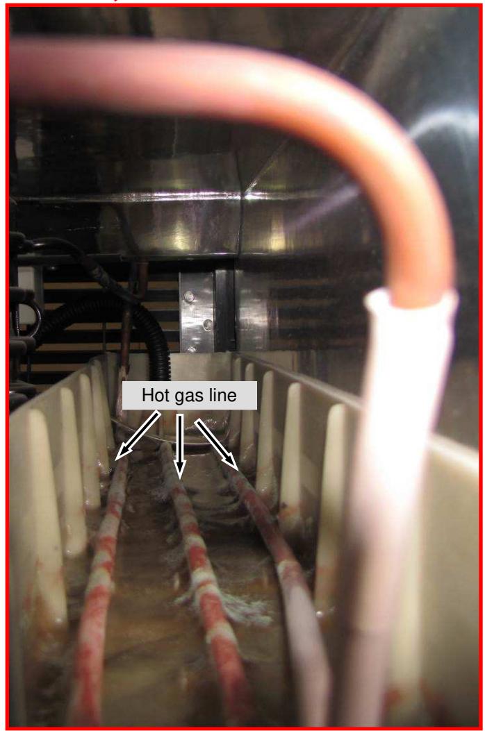
4.2.3 Defrost water evaporation channel and solenoid valve
- The defrost water is collected in the collection pan and fed via a hose to the evaporation channel in the appliance plinth. Here the water is evaporated during normal refrigeration by the dissipated heat of a hot gas line.
- In the defrost phase, the solenoid valve feeds the hot gas directly into the evaporator via a bypass.
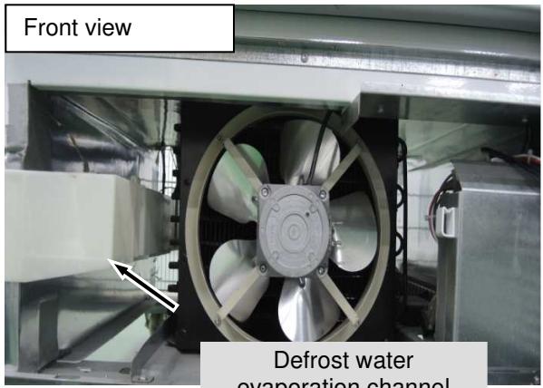
Fig. 4.2.3 / 1
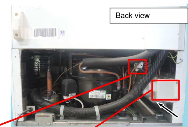
Fig. 4.2.3 / 2
5.0 Assembly instructions/Parts replacement
5.1 Electronics
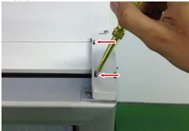
Plinth panel - Remove fastening screws (red arrow) on the upper side of the plinth panel. See (Fig.5.1/1). Pull the panel slightly forwards and then upwards (it is hooked in at the bottom).See (Fig.5.1/2).
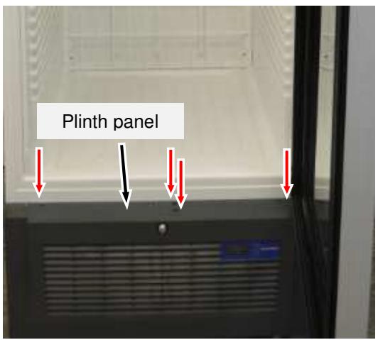
Fig. 5.1 / 1
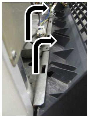
Fig. 5.1 / 2
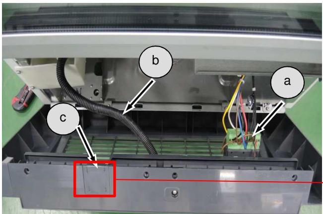
Fig. 5.1 / 3
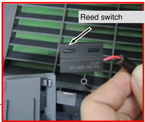
Fig. 5.1 / 3 Location of: a) Electronic controller
b) Condensate hose
c) Reed switch
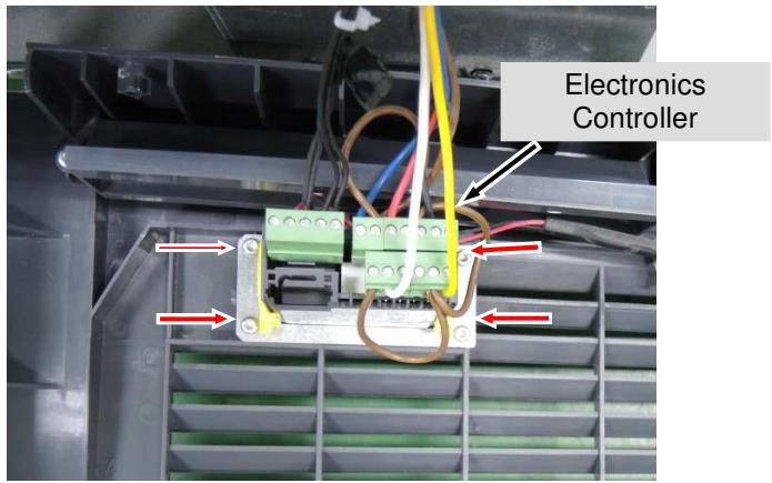
Remove Electronic controller - Remove fastening screws and disconnect cable.(Fig .5.1/4)
5.2 Reed switch
Reed switch: - For Optimization version reed switch is use. See (Fig.5.2/2)
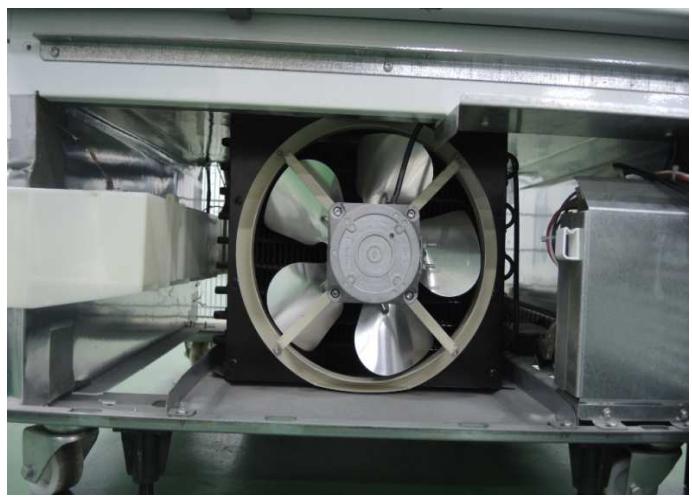
Fig. 5.2 / 1
Reed switch: -The switch is mounted in the plinth panel. See (Fig. 5.2/2)
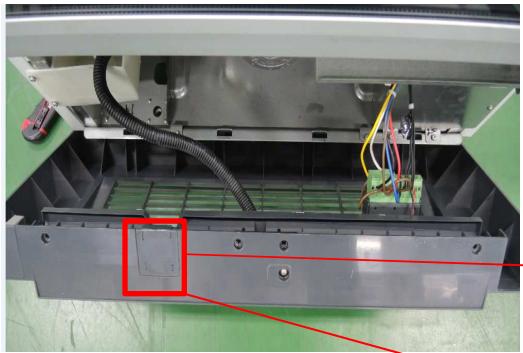
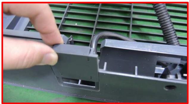
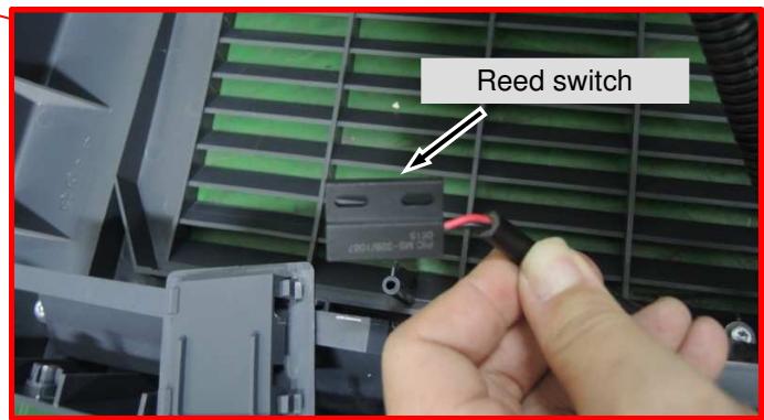
Fig. 5.2/2
5.3 Sensors
5.3.1 Air Sensor
Remove the fan cover: - Remove fastening screw. See (Fig.5.3.1/1)
- Turn the fan cover clock wise to the right and lift off downwards. See (Fig.5.3.1/2).
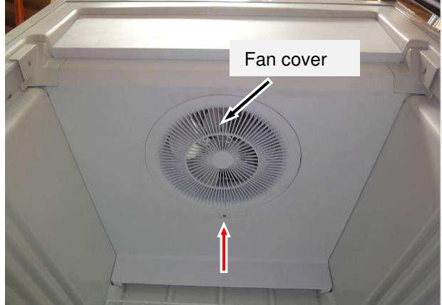
Fig. 5.3.1/1
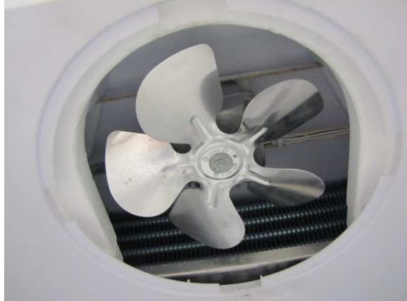
Fig. 5.3.1/2
Remove the holders
- Remove the fastening screws (red arrow). See (Fig.5.3.1/3).
- Remove left and right holder. See (Fig.5.3.1/4).
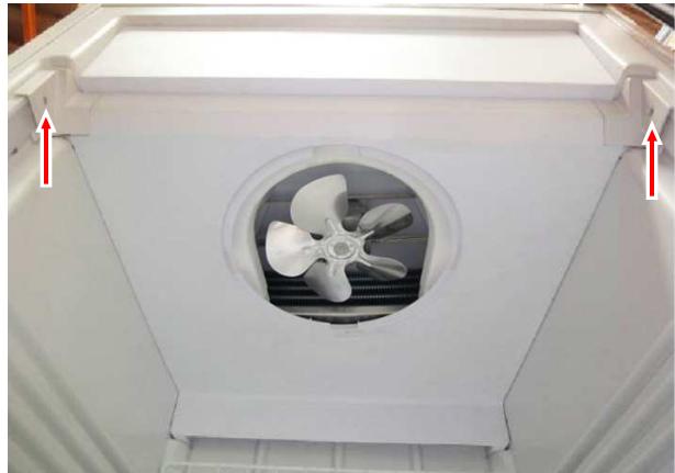
Fig. 5.3.1/3
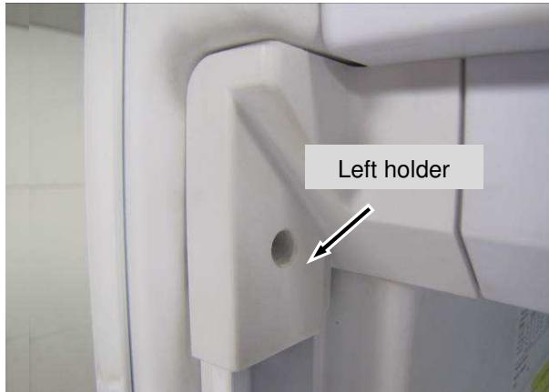
Fig. 5.3.1/4
Remove separating plate - Remove fastening screws. See (Fig.5.3.1/5).
-Pull Separating Plate forward. See (Fig.5.3.1/6).
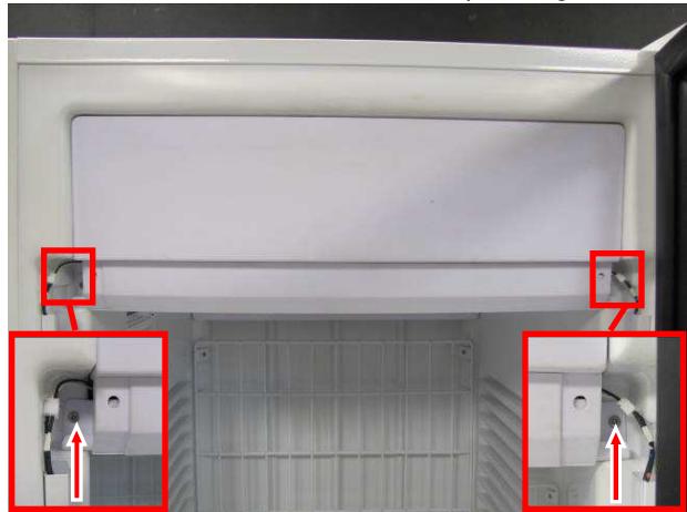
Fig. 5.3.1 /5
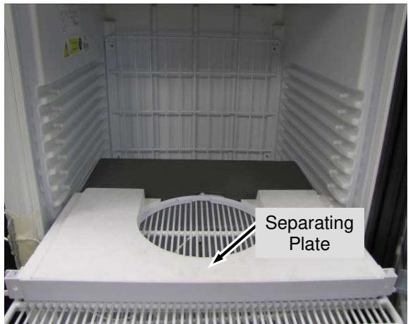
Fig. 5.3.1/6
- Remove the foam. See (Fig.5.3.1/7)
- Remove 4pcs screws to lower down fan holder panel. See (Fig. 5.3.1/8)
- Unclip sensor and remove from spiral band. See (Fig.5.3.1/9).
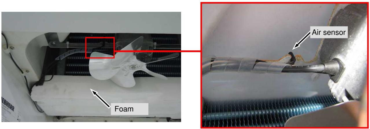
Fig. 5.3.1/7

Fig. 5.3.1/8
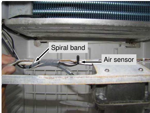
Fig. 5.3.1 /9
5.3.2 Evaporator Sensor
Remove Evaporator Sensor -Remove the foam. See (Fig.5.3.2/1).
-Pull evaporator sensor out of the collection pan (position described below).See (Fig.5.3.2/2).
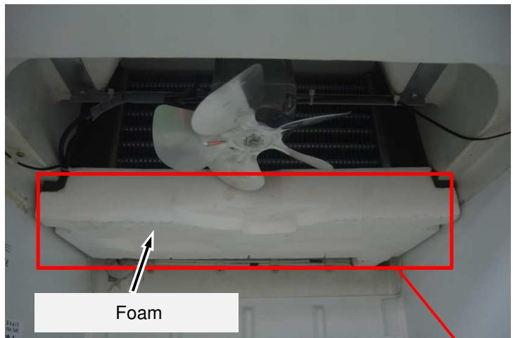
Fig.5.3.2/1
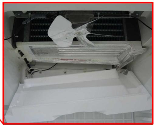
Exact position of evaporator sensor
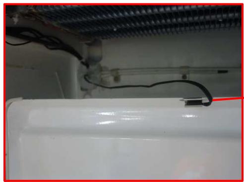
Fig.5.3.2/2
5.3.3 Electronic Controller and Sensors Connections
Remove Back cover -Remove the 6pcs screws and the Back cover. See (Fig.5.3.3/1).
-Cable is directly connected to the electronic controller in the plinth panel. See (Fig.5.3.3/2).
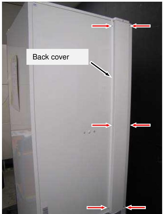
Fig. 5.3.3/1
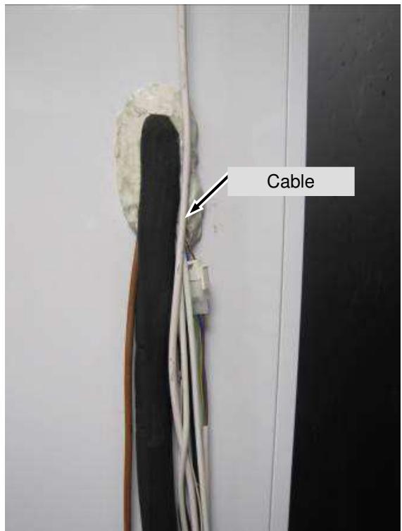
Fig. 5.3.3/2
Cable - Loosen clamps and pull out sensors through the back wall. See (Fig.5.3.3/4)
Sensors are directly connected to the electronic controller in the plinth panel. See(Fig.5.3.3/5).
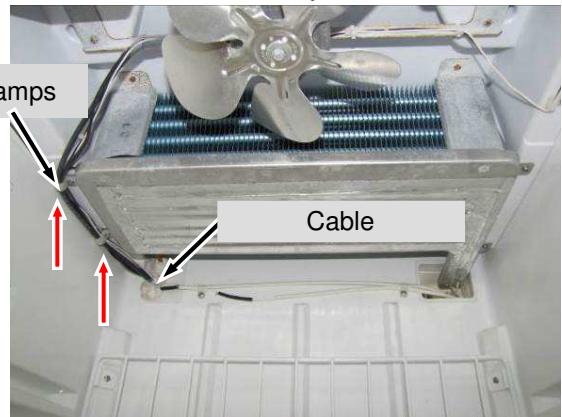
Fig. 5.3.3/4
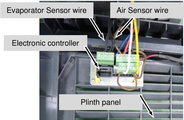
Fig. 5.3.3 /5
5.4 Evaporator fan
Remove separating plate - Remove separating plate (see chapter 5.3).
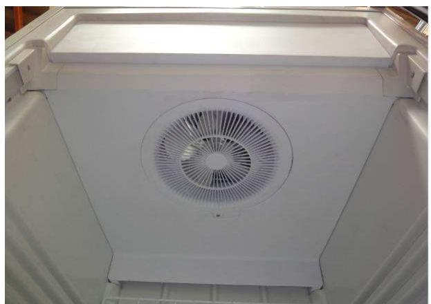
Fig. 5.4 / 1
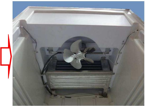
Fig. 5.4 / 2
Remove fan holder panel -Remove fastening screws. See (Fig.5.4/3).
-Lower fan holder panel together with the fan. See (Fig.5.4/4).
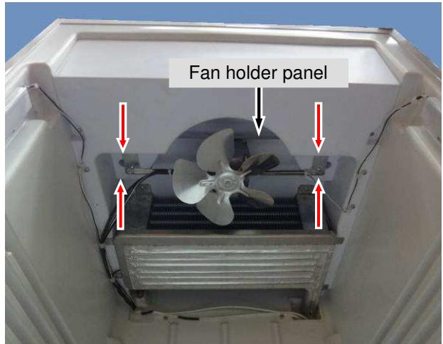
Fig. 5.4 / 3
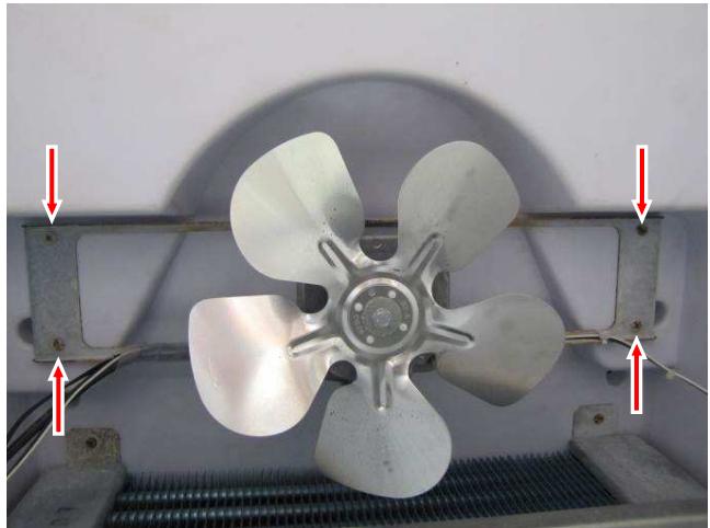
Fig. 5.4 / 4
- Disconnect the cable at the back and pull it through into the interior. See (Fig.5.4/5).
- Remove the fastening screws. See (Fig 5.4/6).
- Remove fan. See (Fig 5.4/6).
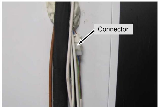
Fig. 5.4 / 5
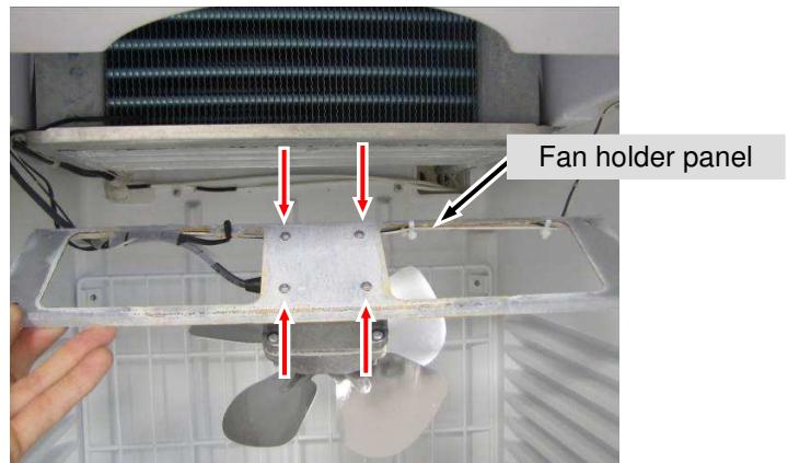
Fig. 5.4 / 6
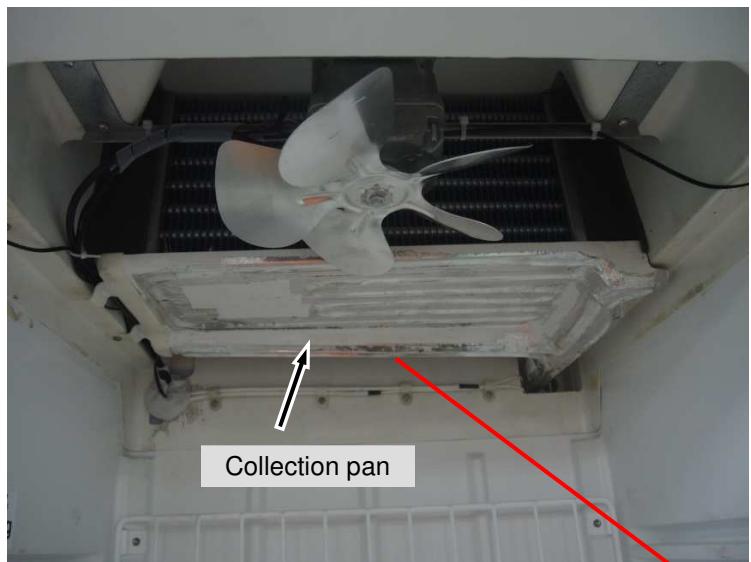
5.5 Defrost water collection pan with heater
Separating plate: - Remove the foam (see chapter 5.3).
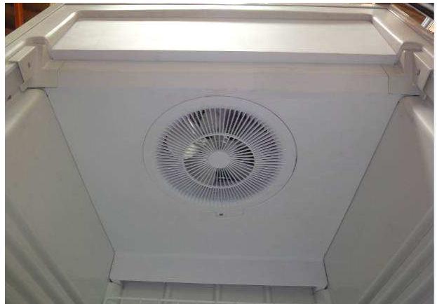
Fig. 5.5 / 1
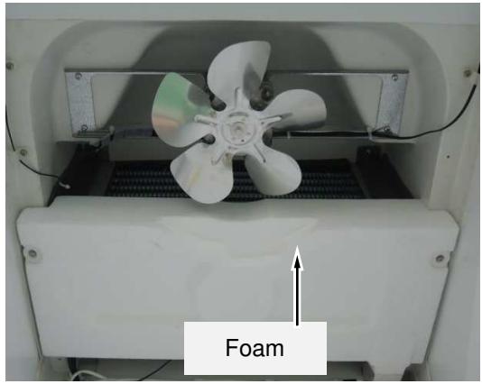
Fig. 5.5 / 2
Remove Collection Pan - Remove fastening screws and lower the collection pan. See (Fig.5.5/3).
- The heater is glued to the underside of the pan. See (Fig.5.5/4).
- Disconnect the cables at the back and pull through the rear wall into the interior. See (Fig.5.5/5).
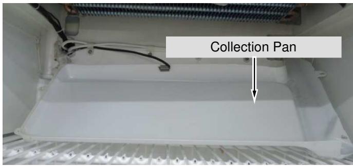
Fig. 5.5 /3
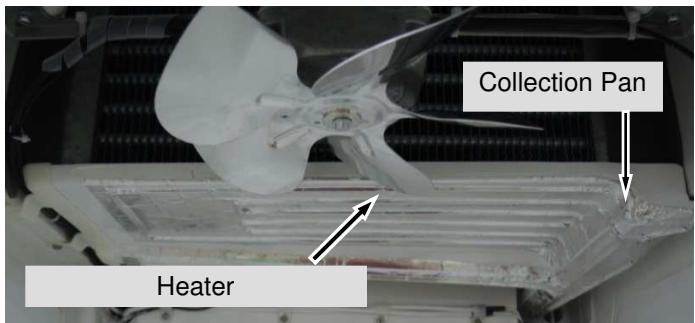
Fig. 5.5 /4
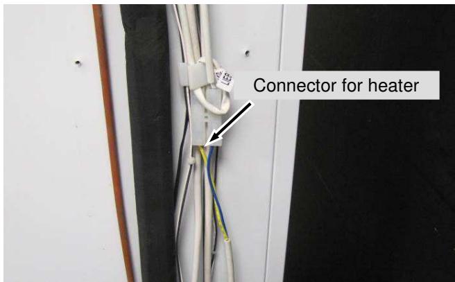
Fig. 5.5 /5
5.6 LED lighting
Display lighting (FDv 4613):
- Remove screws and pull display upwards. See (Fig.5.6/1).
- Remove the LED strip fastening screws. See (Fig.5.6/2).
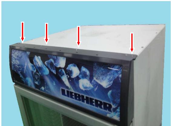
Fig. 5.6/1
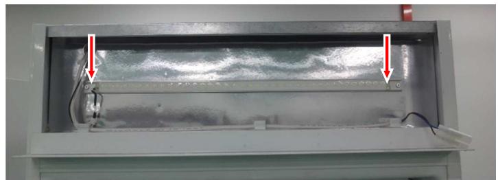
Fig. 5.6 / 2
Interior light:
- Remove fastening screws and holder above and below. See (Fig.5.6/3)
- Remove fastening screws and light cover. See (Fig.5.6/3).
- Disconnect LED strip and remove. See (Fig.5.6/4).
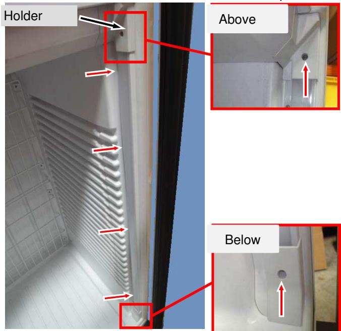
Fig. 5.6 /3
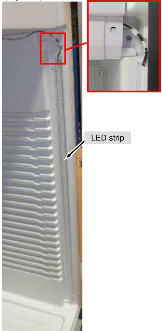
Fig. 5.6 /4
Remove Main adaptor: - Remove two pcs screws and take out main adaptor. See (Fig.5.6/5).
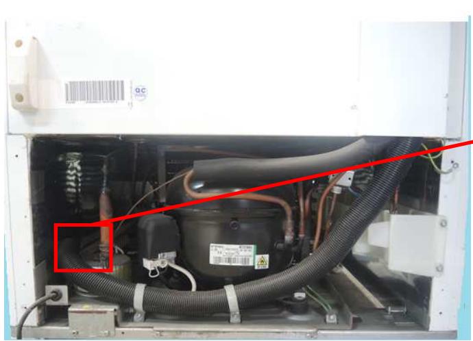
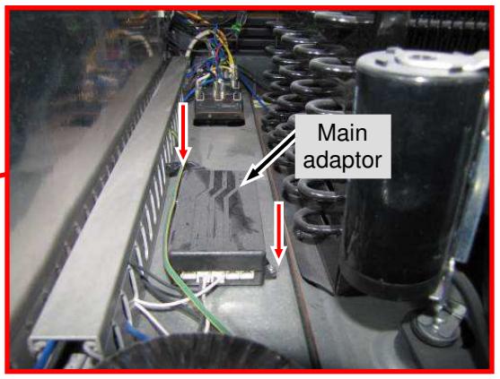
Fig. 5.6 /5
5.7 Transformer
Remove Transformer: - Remove 1pcs screw (red arrow) and take out transformer. See (Fig.5.7/1)
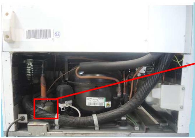
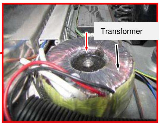
Fig. 5.7 / 1
5.8 Condenser fan
Remove Condenser fan - Remove plinth panel (chapter 5.1)
- Remove screws and take out fan together with holder. See (Fig.5.8/1).
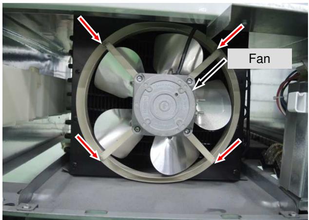
Fig. 5.8 / 1
5.9 Exchange of seal
Remove seal:
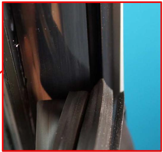
- Take hold of the seal at the bellows or magnetic strip and gently move it to and fro to draw it out of the door frame. See (Fig.5.9/1).
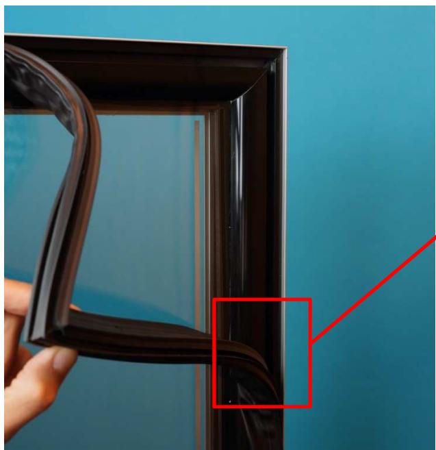
Fig. 5.9/1
Installing the seal:
- First, press the new seal into the door frame at the corners.
- Then press the seal completely into the groove all along the door frame.
NOTE: The dart profile of the seal must be completely "hooked into" the groove.
I.e. draw the bellows slightly to one side and check the correct position of the seal all the way round.
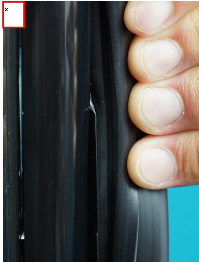
Fig. 5.9/2
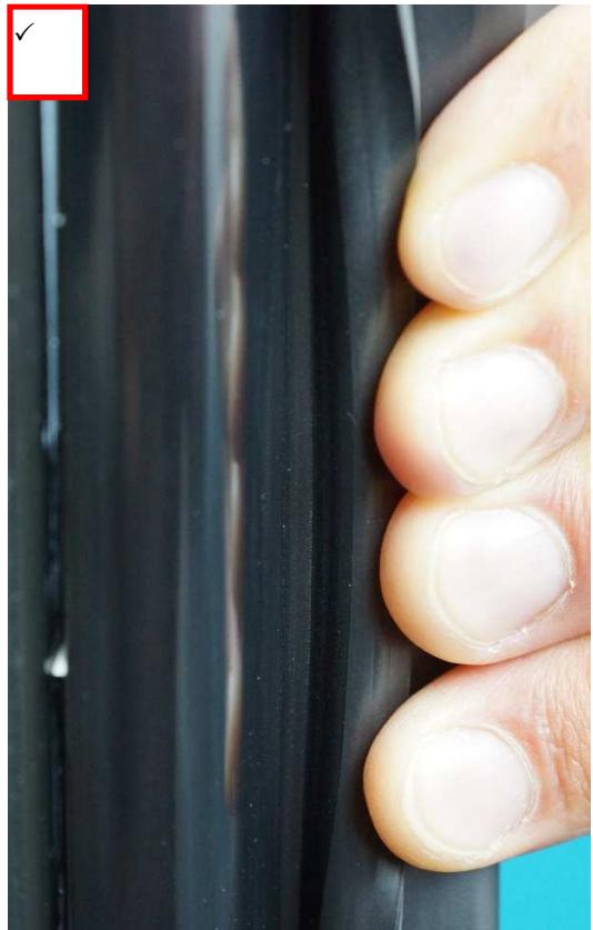
Fig. 5.9/3
5.10 Door exchange
Remove top covers:
- With Fv 3613, unclip the cover of the hinge plate. See (Fig. 5.10/1). Remove fastening screws from the top of the appliance. See (Fig. 5.10/2).
- With FDv 4613 remove the fastening screws and pulls the display upwards. See (Fig. 5.10/3).
FV 3613:
Fig. 5.10/1
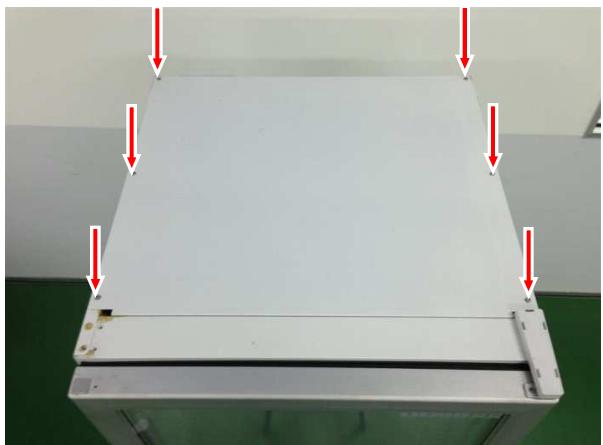
Fig. 5.10/2
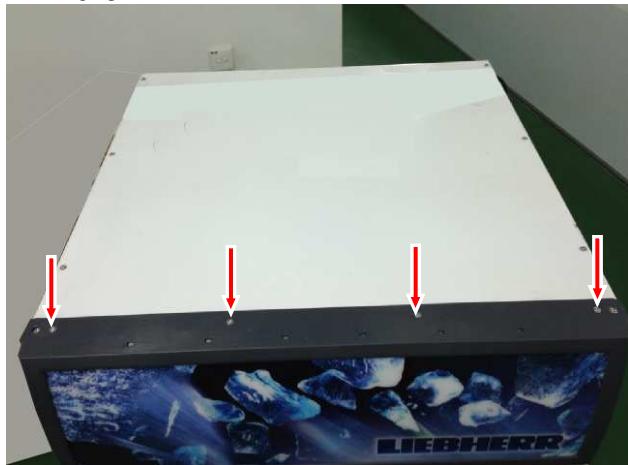
FDv 4613:
Fig. 5.10/3
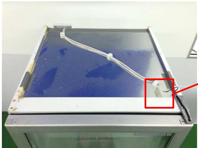
Disconnect heater:
- Take hold of the cables at the cable lugs using long-nosed pliers and pull them out of the connector. See (Fig.5.10/4) and (Fig.5.10/5).
Fv 3613:
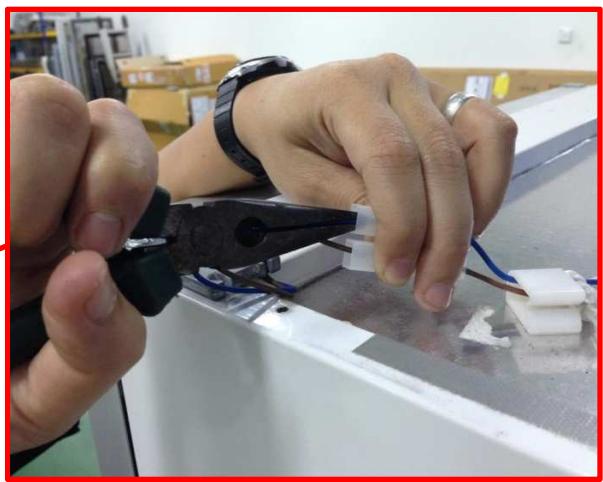
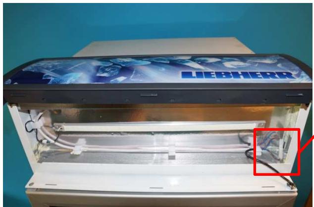
Fig. 5.10/4
FDv 4613:
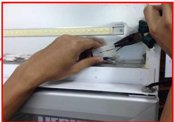
Fig. 5.10/5
Plinth panel:
- Remove stoppers and fastening screws on the upper side of the plinth panel.
(Fig. 5.10/6).
- Pull the panel slightly forwards and then upwards (it is hooked in at the bottom)
(Fig. 5.10/7).
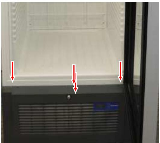
Fig. 5.10/6
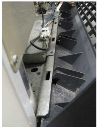
Fig. 5.10/7
Dismounting the door:
- Remove the inner fastening screw(red arrow) of the lower turn hinge. See (Fig. 5.10/8).
- Prepare the heater cable so that it can be pulled downwards through the turn hinge. See (Fig. 5.10/9).
NOTE: The door must either be held by a 2nd. person or supported by an object.
- Hold the turn hinge with pliers (pre-tensioning of the torsion rod) and loosen both the outer screws. See (Fig. 5.10/10).
- Pull door together with turn hinge (Fig. 5.10/11) downwards (pull cable through the hinge plate) and remove.
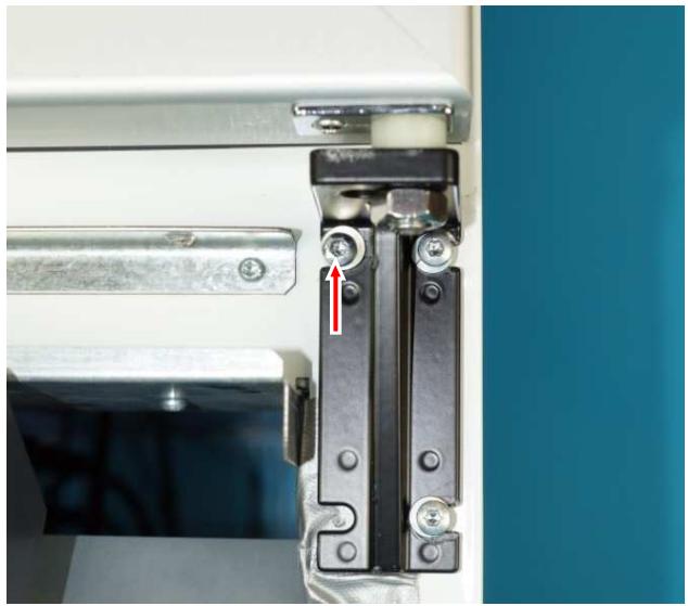
Fig. 5.10/8
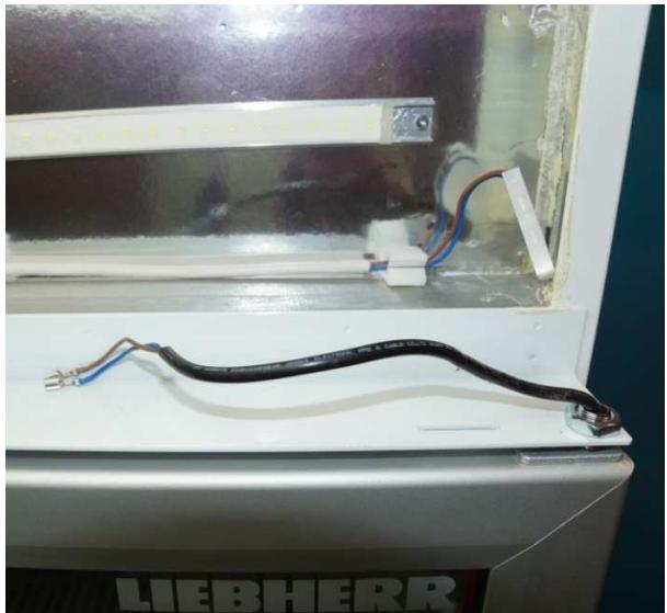
Fig. 5.10/9
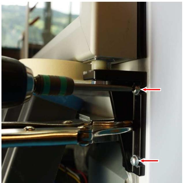
Fig. 5.10/10
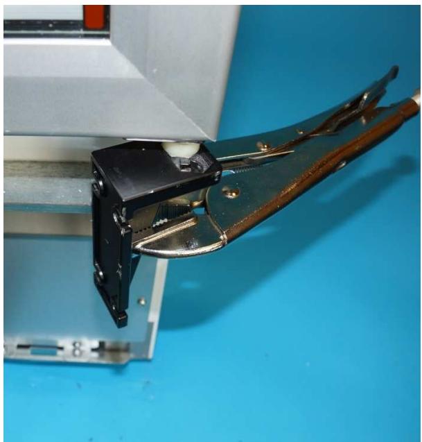
Fig. 5.10/11
Bottom turn hinge:
- Unscrew nut and remove turn hinge. See (Fig. 5.10/12).
- Place turn hinge on torsion rod of the new door and fix with nut.
NOTE: The turn hinge must be positioned so that when mounting the door in closed condition there is a pre-tension of at least 90^ . See (Fig. 5.10/13).
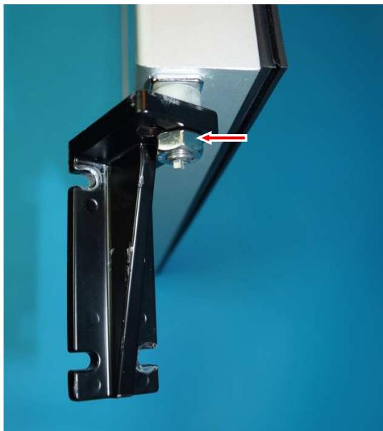
Fig. 5.10/12
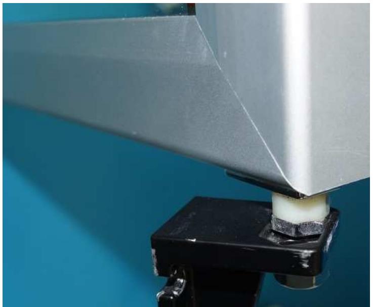
Fig. 5.10/13
Mounting the door:
- Thread the heater cable through the upper hinge plate. See (Fig. 5.10/14).
NOTE: The door must either be held by a 2nd. person or supported by an object. - Hold the hinge plate with pliers, pre-tension and set into the (Fig. 5.10/15) screws (Fig. 5.10/16).
- Screw the turn hinge tight and connect the heater.
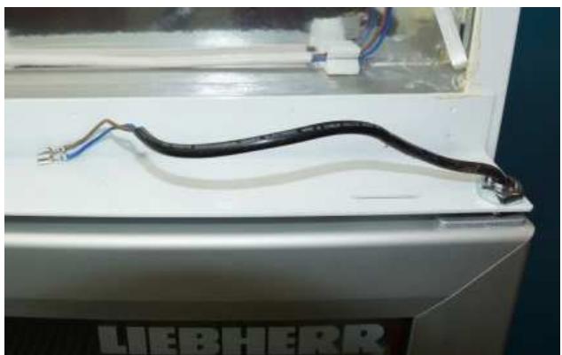
Fig. 5.10/14
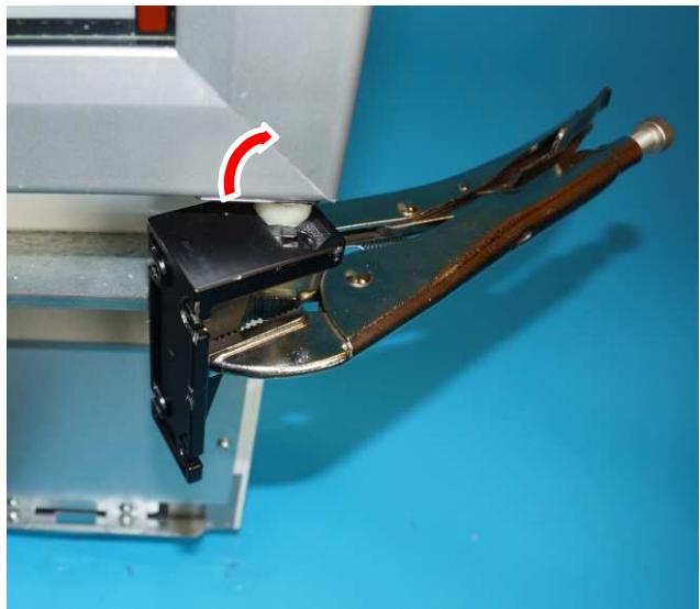
Fig. 5.10/15
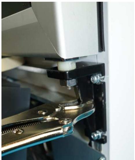
Fig. 5.10/16
Covers:
- Check whether the door closes correctly even with a small opening angle.
- Mount the plinth panel and top covers.
5.10.1 Changing over the door hinges
The models are available ex-factory with door hinges on the left (special version).
However, the door is constructed to allow a retrofit change-over of the door hinges (right to left / left to right). This task must be carried out by professional technicians.
The process is largely identical to that of changing the door. However, on the dismounted door, the torsion rod must be changed over and the heater cable worked on.
Remove top cover: - Unclip the top cover. See (Fig.5.10.1/1).
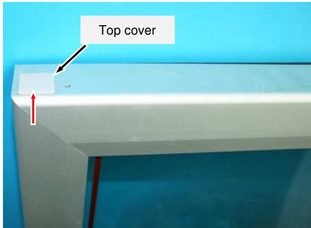
Fig. 5.10.1/1
Top hinge bushing:
-
Remove screw. See (Fig. 5.10.1/2)
-
Pull out hinge bushing. See (Fig. 5.10.1/3).
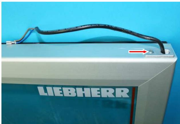
Fig. 5.10.1/2
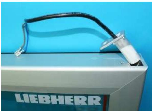
Fig. 5.10.1/3
Deactivate heater cable:
- Pinch off wires (Fig. 5.10.1/4) and insulate with push-on connector (Fig. 5.10.1/5).
- Insert the cable into the door frame (Fig. 5.10.1/6), supply with power there and close the opening with the cover (Fig. 5.10.1/7).
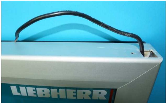
Fig. 5.10.1/4
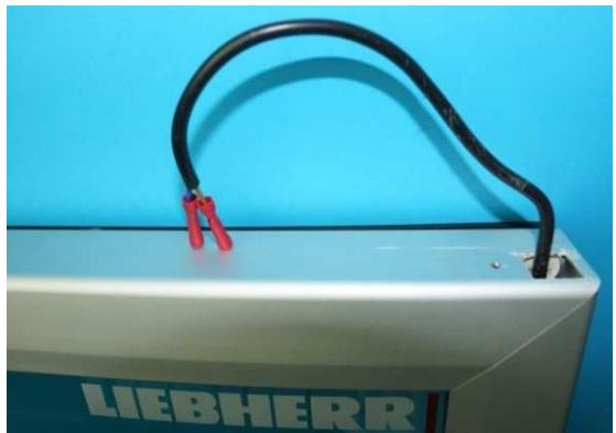
Fig. 5.10.1/5
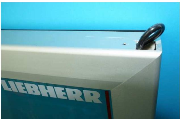
Fig. 5.10.1/6
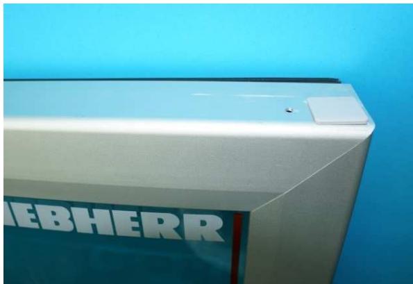
Fig. 5.10.1/7
Activate heater cable:
- Pull cable for left-hand hinges out of the door frame. See (Fig. 5.10.1/9).
- Pinch off the protective caps on the wires and mount the hinge bushing See (Fig. 5.10.1/10).
- Add on wires with terminals using push-on connectors. See (Fig. 5.10.1/11). New terminals can of course be directly pushed onto the wires.
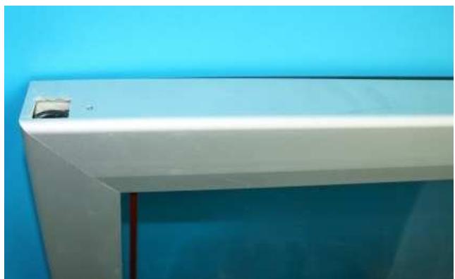
Fig. 5.10.1/8
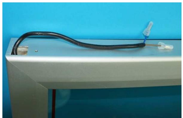
Fig. 5.10.1/9
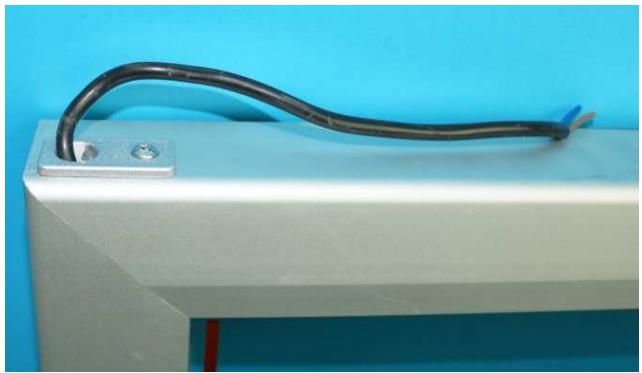
Fig. 5.10.1/10
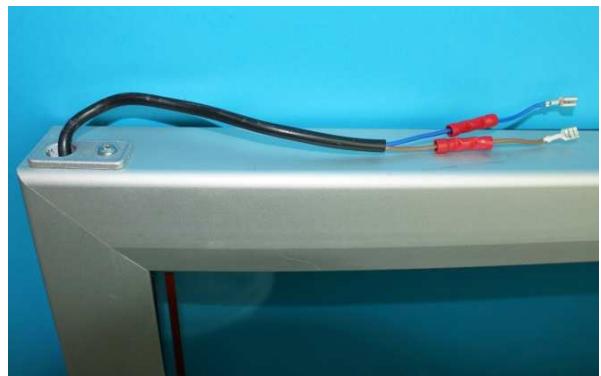
Fig. 5.10.1/11
Torsion rod:
- Pull out torsion rod. See (Fig.5.10.1/12)
- Put hinge bushing onto the other side and re-insert the torsion rod there.
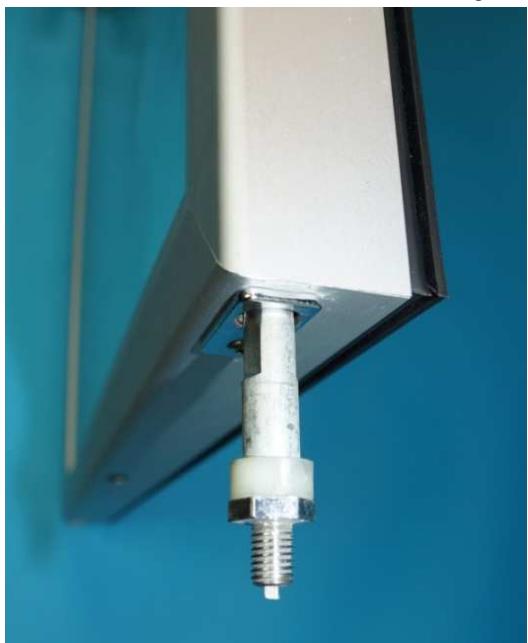
Fig. 5.10.1/12
6.0 Technical Data
| Evaporator pan heater: | Wattage: | approximately 65 watts |
| Voltage: | 220-240 Volt 50/60Hz | |
| LED lighting: | Wattage: | approximately 19.5 watts |
| Voltage: | 220-240 Volt 50/60Hz | |
| Condenser fan: | Wattage: | approximately 60 watts |
| Speed: | 1300 rpm | |
| Voltage: | 220-240 Volt, 50/60 Hz | |
| Evaporator fan: | Wattage: | approximately 13 watts |
| Speed: | 1550 rpm | |
| Voltage: | 220-240 Volt, 50/60 Hz | |
| Solenoid valve: | Wattage: | approximately 4.5 watts |
| Voltage: | 220-240 Volt, 50/60 Hz |
Sensor values:
| Temperature [°C] | Resistance value [kOhm] |
| 50 | approximately 4 |
| 45 | approximately 4.9 |
| 40 | approximately 5.8 |
| 35 | approximately 6.9 |
| 30 | approximately 8.3 |
| 25 | approximately 10 |
| 20 | approximatley 12 |
| 15 | approximatley 14.7 |
| 10 | approximately 18 |
| 5 | approximately 22 |
| 0 | approximately 27 |
| -5 | approximately 33.9 |
| -10 | approximately 42.3 |
| -15 | approximately 53.4 |
| -20 | approximately 67 |
| -25 | approximately 86.4 |
| -30 | approximately 111.3 |
| -35 | approximately 144 |
| -40 | approximately 185 |
7.0 Messages and error codes
7.1 Testing the evaporator temperature
- Press the "Mute" and "Set" button simultaneously for more than 5 seconds until the display show "0" to access the parameter.
- Press the "Light" button repeatedly until the display show "17"(password)and then press "Set" button.
- Press the "Defrost" button repeatedly until the parameter "d/1" is displayed.
- After pressing the "Set" button the current temperature of the evaporator sensor is displayed.
7.2 Calling up the minimum and maximum internal temperature
-
Press the "Mute" and "Set button simultaneously for more than 5 seconds until the display show "0" to access the parameter
-
Press the "Light" button repeatedly until the display show "17"(password)and then press "Set" button.
-
Press the "Defrost" button repeatedly until the parameter "rt" is displayed.
After pressing the "Set" button, the time period in which the internal temperature was measured is displayed. -
Press the "Defrost" button repeatedly until the parameter "rL" is displayed.
-
After pressing the "Set" button, the coldest internal temperature within the period is displayed.
- Press the "Defrost" button repeatedly until the parameter "rH" is displayed.
-
After pressing the "Set" button, the warmest internal temperature within the period is displayed.
Deleting the saved values:
Press the "Mute" and "Set" button simultaneously for more than 5 seconds until the display show "0" to access the parameter.
Press the "Light" button repeatedly until the display show "17"(password)and then press "Set" button.
- Press the "Defrost" button repeatedly until the parameter "rt" is displayed.
-
After pressing the "Set" button, the period in which the internal temperature was measured is displayed.
- Press and hold down the "Defrost" button for five seconds -> "rES" will appear in the display.
7.3 Parameters (with password "17")
- Press the "Mute "and "Set" button simultaneously for more than 5 seconds until the display show "0" to access parameter.
- Press the "Light" button repeatedly until the display show "17" (password) and then press "Set".
-Use the "Light" or the "Defrost" button to select the parameters. - Pressing the "Set" button will display the relevant value.
- Repeat pressing of the "Set" button will once more display the parameter.
- Press the "Mute" button (5 seconds) to leave the parameter level.
| Parameters | Value | Notes | |
| St | Pre-set target value | -18 | Set value in °C |
| rd | Actuating variable (hysteresis) | 2 | |
| rt | Temperature monitoring interval | --- | |
| rH | Max. temperature | --- | |
| rL | Min. temperature | --- | |
| c2 | Min. compressor OFF time | 6 | minutes |
| dI | Defrost interval | 6 | hours |
| dt1 | Evaporator temperature at termination of defrosting | 14 | °C (57.2°F) |
| dt2 | Auxiliary evaporator temperature at termination of defrosting | 0 | °C (32°F)Not relevant |
| dP1 | Max. defrosting time | 25 | minutes |
| dP2 | Max. defrosting time auxiliary evaporator | 1 | Not relevant |
| d4 | Enable defrost at start-up | 1 | |
| d5 | Defrost delay at start-up | 25 | minutes |
| dd | Drip-off time after defrosting | 2 | minutes |
| d8 | Alarm delay after defrosting | 1 | hour |
| d8d | Alarm delay after door opening | 10 | min |
| d/1 | Evaporator sensor display | --- | |
| d/2 | Evaporator sensor 2 display | --- | Not relevant |
| AL | Lower temperature alarm limit | 5 | °C (41°F) |
| AH | Upper temperature alarm limit | 5 | °C (41°F) |
| Ad | Alarm delay | 15 | minutes |
| F1 | Fan start temperature | 5 | °C (41°F) |
| Fd | Fan stop after drip-off phase | 9 | minutes |
Changes to the parameters may only be made after consultation with the customer service centre responsible!
7.4 Error codes
| Error code | Defective component | Audible alarm/alarm contact | Emergency mode |
| E0 | Air sensor | ON/ON | 12 minutes ON, 15 minutes OFF |
| E1 | Evaporator sensor | ON/ON | Normal mode(Defrosting phase terminated by time limit) |
| EE | Electronics defective(operating parameters) | ON/ON | All off |
| EF | Electronics defective(control parameters) | ON/ON | All off |
7.5 Status messages
| Message | Condition | Audible alarm/alarm contact |
| HI | High temperature alarm | ON / ON |
| LO | Low temperature alarm | ON / ON |
| Ed1 | Defrost phase time-terminated | OFF / OFF |
| dor | Door alarm | ON / ON |
| dFb | Manual defrosting started | |
| dFE | Manual defrost phase terminated | |
| ON | Appliance switched ON | |
| OFF | Appliance switched OFF |