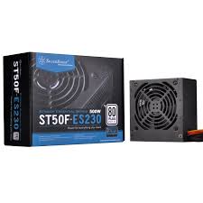
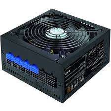
STRIDER ESSENTIAL ST50F-ES 80PLUS - Computer power supply SILVERSTONE - Free user manual and instructions
Find the device manual for free STRIDER ESSENTIAL ST50F-ES 80PLUS SILVERSTONE in PDF.



| Product type | Computer power supply |
| Brand | SILVERSTONE |
| Model | STRIDER ESSENTIAL ST50F-ES 80PLUS |
| Rated power | 500 W |
| Certification | 80 PLUS |
| Form factor | ATX |
| Dimensions (L x W x H) | 150 x 140 x 86 mm |
| Weight | 1.5 kg |
| Input voltage | 100-240 V AC |
| Input frequency | 50-60 Hz |
| Power factor correction | Active PFC |
| Main connector | ATX 24-pin (compatible with 20-pin) |
| CPU connectors | 1 x EPS 8-pin (compatible with 4-pin) |
| PCI-E connectors | 2 x 6+2-pin |
| SATA connectors | 6 x SATA |
| Peripheral connectors | 4 x Molex 4-pin |
| Floppy connector | 1 x 4-pin |
| Safety | Do not open; use in a dry environment; do not block openings |
| Maintenance | Clean with a dry cloth; unplug before cleaning |
| Warranty | Limited warranty covering manufacturing defects; excludes damage from misuse or natural disasters |
Frequently Asked Questions - STRIDER ESSENTIAL ST50F-ES 80PLUS SILVERSTONE
User questions about STRIDER ESSENTIAL ST50F-ES 80PLUS SILVERSTONE
0 question about this device. Answer the ones you know or ask your own.
Ask a new question about this device
Download the instructions for your Computer power supply in PDF format for free! Find your manual STRIDER ESSENTIAL ST50F-ES 80PLUS - SILVERSTONE and take your electronic device back in hand. On this page are published all the documents necessary for the use of your device. STRIDER ESSENTIAL ST50F-ES 80PLUS by SILVERSTONE.
USER MANUAL STRIDER ESSENTIAL ST50F-ES 80PLUS SILVERSTONE
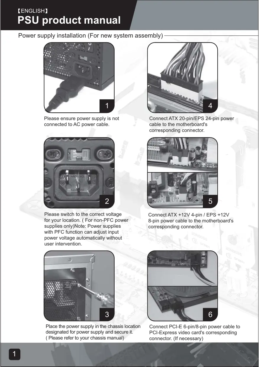
Power supply installation (For new system assembly)
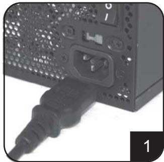
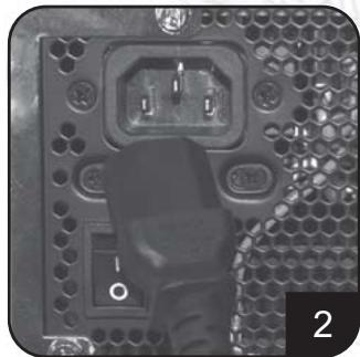
Please ensure power supply is not connected to AC power cable.
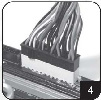
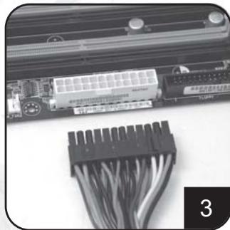
Connect ATX 20-pin/EPS 24-pin power cable to the motherboard's corresponding connector.
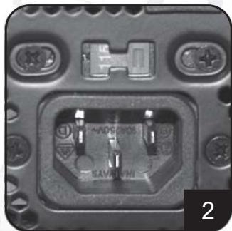
Please switch to the correct voltage for your location. (For non-PFC power supplies only)Note: Power supplies with PFC function can adjust input power voltage automatically without user intervention.
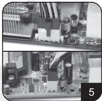
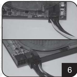
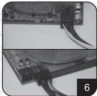
Connect ATX +12V 4-pin / EPS +12V 8-pin power cable to the motherboard's corresponding connector.
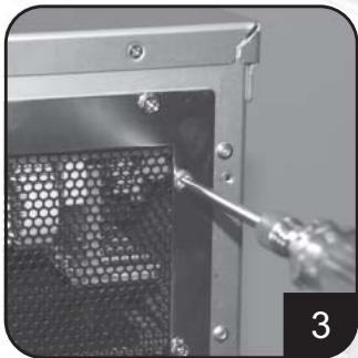
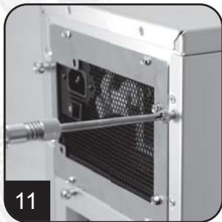
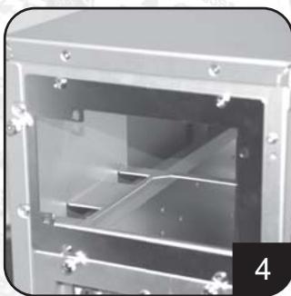
Place the power supply in the chassis location designated for power supply and secure it. (Please refer to your chassis manual)
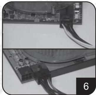
Connect PCI-E 6-pin/8-pin power cable to PCI-Express video card's corresponding connector. (If necessary)
Power supply installation (for new system assembly)
Connect SATA power cables to SATA hard drives or devices.
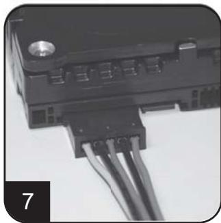
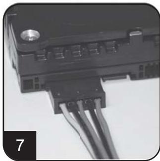
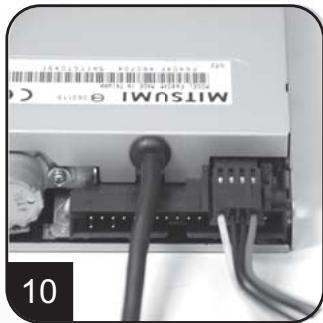
Connect small 4-pin power cable to floppy drives or other compatible devices
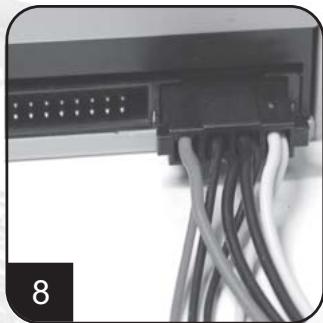
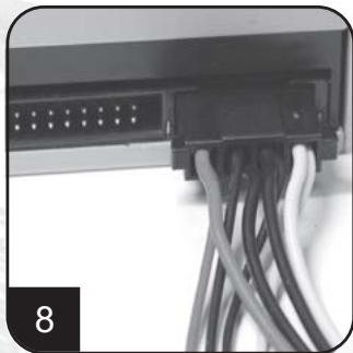
Connect 4-pin peripheral power cables to IDE hard drives, optical drives or other devices.
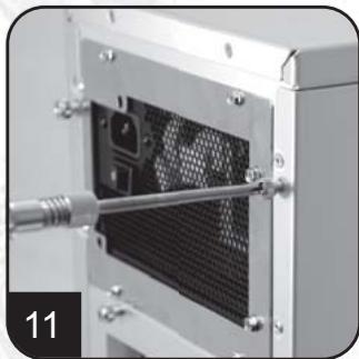
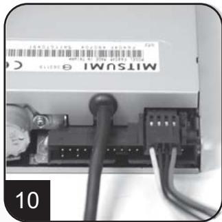
Reinstall chassis's cover, and secure it. (Please refer to the installation of chassis)
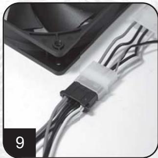
Connect 4-pin peripheral power cables to fans utilizing the peripheral connectors. (DC +12V variety)
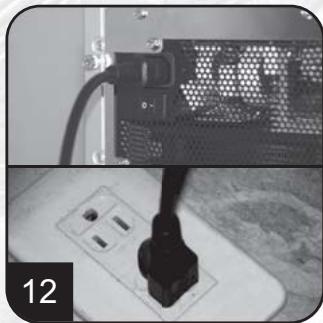
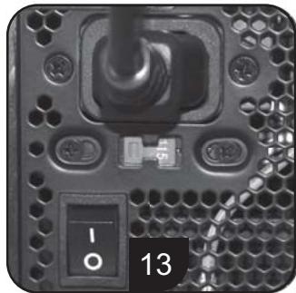
Connect AC power cable to the power supply. (Caution: please do not use extension socket, if using extension socket is necessary, avoid combined usage with other higher powered household appliances such as TV, audio amplifier, etc...)
Power supply installation (For new system assembly)
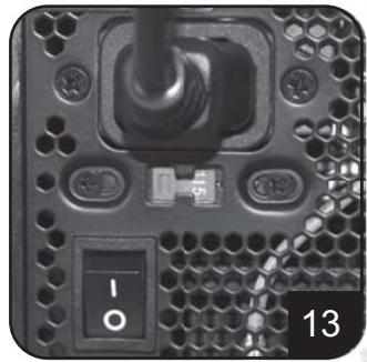
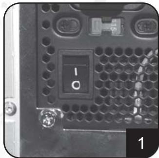
Turn on the power supply by switching to "I" (I/O) mode.
Caution: The power supply is on standby now. System on and off is controlled by the motherboard.
(Pleases refer to the motherboard manual)
Power supply installation (For replacement)
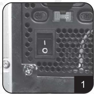
After turning off the system, switch the power supply to "O" position to disable system standby and make sure the system is no longer drawing any power.
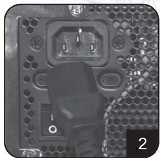
Remove AC power cable from the power supply.
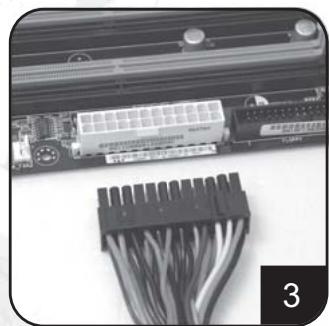
Remove all power supply cables connected to the motherboard, video card, hard drive and other device.
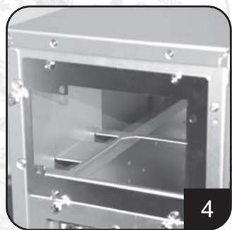
Remove power supply from the chassis. (Please refer to your chassis's installation manual.)
- Please refer now to Step 1 of "Power supply installation (for new system assembly)"
Power supply usage notes and caution
- The power supply includes dangerous high voltage; please do not open the power supply in any condition. Once the power supply enclosure is opened, it will no longer be covered under warranty.
- Please use power supply in safe and dry surroundings.
- Please do not obstruct, insert, or put anything into power supply's vents and any other openings.
- The AC cable included with the power supply has been stringently examined by the factory for defects and quality so please use only the AC cable supplied with your power supply. AC power cable manufactured by a third party may produce incompatible results and possibly cause damage to your system or power supply.
- This product is designed for indoor use only.
Troubleshooting
If your power supply is not operating properly, please refer to the following steps:
- Please make sure the voltage switch is in the correct mode for use in your location (115V or 230V). (For power supplies without PFC function only)
- Please ensure AC power cable is connect to the power supply.
- Please make sure power supply's "I/O" is switched to "I" mode.
- Please double check to see if all motherboard, video card(s), hard drives, and devices' cables are connected correctly.
- Please turn off the power supply by switching the "I/O" to "O" mode. Wait for approximately 5 minutes for the power supply to reset its protection mechanisms, then switch on "I" mode and reboot the system.
Caution: The power supply includes dangerous high voltage; please do not open the power supply under any circumstances. Once the power supply enclosure is opened, it will no longer be covered under warranty.
Power supply connectors

ORANGE +3.3V ORANGE +3.3V BLACK GND RED +5V BLACK GND RED +5V BLACK GND GREY PS-ON PURPLE +5Vsbl YELLOW +12V YELLOW +12V ORANGE +3.3V
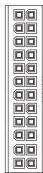
ORANGE +3,3V BLUE -12V
BLACK GND
GREEN PS-ON
BLACK GND
BLACK GND
BLACK GND
N/C
RED +5V RED +5V RED +5V BLACK GND
ORANGE +3.3V ORANGE +3.3V BLACK GND RED +5V BLACK GND RED +5V BLACK GND GREY PS-ON PURPLE +5Vsb YELLOW +12V
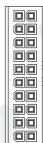
ORANGE +3.3V BLUE -12V
BLACK GND
GREEN PS-ON
BLACK GND
BLACK GND
BLACK GND
N/C
RED +5V RED +5V


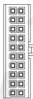
EPS 24-pin motherboard power connector
Support the latest ATX/BTX PC motherboard Support EEB/CEB server/workstation motherboard
ATX 20-pin motherboard power connector
Support ATX PC motherboard
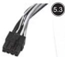
EPS 8-pin CPU +12V power connector
Support Dual CPU server/ workstation Support latest single CPU system
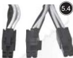
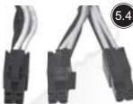
ATX 4-pin CPU +12V power connector
Support latest single CPU system.
PCI-E 6-pin power connector
Support high-end PCI-Express video card, some high-end video cards may require two PCI-E 6 pin connectors.
PCI-E 8 pin power connector
Support high-end PCI-Express video card, some high-end video cards may require another PCI-E 6-pin connector in addition to PCI-E 8pin connector.
SATA hard disk power connector
Support latest SATA hard drives and devices
Standard 4-pin peripheral power connector
Support IDE/SCSI hard drives, optical drives, fans, etc...
Small 4-pin floppy power connector
Support standard floppy drives or compatible devices
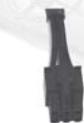
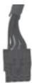
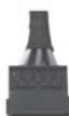
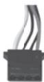


YELLOW -12V YELLOW +12V YELLOW +12V

BLACK
BLACK
BLACK
GND SENSE GND

YELLOW +12V BLACK GND ORANGE +3.7V BLACK ORANGE +3.3V


Power supply connectors
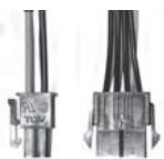

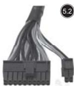
Converting wire
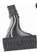
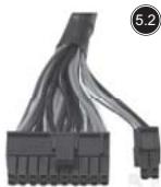
EPS 8-pin connector to convert into ATX 4-pin connector
Caution:
- Please turn off your system and switch to "O" mode on the power supply before attaching or detaching power connectors.
- All power connectors are keyed to prevent incorrect connections. If you cannot connect them easily, please double check to ensure the connector's direction and type before attempting to connect again. Do not attach the connector by force; incorrect connection will damage power supply or devices in your system.
- The converting wire (picture 5.10) can only be attached with EPS 8-pin connector to convert into ATX 4-pin connector. Incorrect connection will damage power supply or devices in your system.
The connectors shown above may differ depending on the model of your power supply.
Warranty
Product component defects or damages resulted in defective production is covered under warranty. Damages resulted with the following conditions will be fixed or replaced under SilverStone's jurisdiction.
- Usage in accordance with instructions provided in this manual, with no misuse, overuse, or other inappropriate actions.
- Damage not caused by natural disaster (thunder, fire, earthquake, flood, salt, wind, insects, animals etc...)
- Product is not disassembled, modified, or fixed. Components not disassembled or replaced.
- Warranty mark/stickers is not removed or broken.
Loss or damages resulted from conditions other than ones listed above are not covered under warranty.
Support ATX PC Motherboard
EPS 8-pin CPU +12V Strombuchse/Stecker
Unterstutz Dual CPU Server/Workstation
Unterstutz neuestes Single CPU System
ATX 4-pin CPU +12V Strombuchse/Stecker
Unterstutz neuestes Single CPU System
PCI-E 6-pin Strombuchse/Stecker
Small 4-pin Floppy Strombuchse/Stecker
m = 311
YELLOW +12V BLACK GND RED +5V BLACK GND ORANGE +3.3V


.
EPS 8-pin CPU +12V power connector
CoéuHnIte cunlOBoKa6eJIb ATX +12V 4-pin / EPS +12V 8-pin c coOTBeTcTBUOuM KOHNekTopOM MaTePnHcKoI PNaTbl.
CoeHInHTe cINIOBoi Ka6eJIb PCI-E 6-pin/8-pin c COOTBECTBYOULIM KOHNKETOPOM PCI-3KcPpeCCHo BnDeo KapTBI (B Clyue HeoXoDMOCTN).
PykoBODCTBO npOdyKcIN PSU
YctahOBKa 3JIeKTPoPNTaHnA (IINr c6OpKn HOBOI CnCTEmbl)
CoeHInHTe cnIObIe Ka6eN SATA c dpaBepaMn JecTKOro DnCKa nn yCtpoiCTBaMn SATA.
CoeHnHTe MaHbKn 4-pin cInnoBoi Ka6ebc dpaBepaMn r6kOro DnCKa nnDpyHMn COBMecTmblIMyUCTpoCTBaMn.
CoedHnHte 4-pin nepi#pepniHbIe cnIObIe Ka6eTn C dpaiBepaMn JxecTKoTo Dmoka IDE,OrTMHeckMn dpaiBepaMn HIN dpyTMMU yCTpoiCTBaMn.
YctaHOBKa 3NeKtpoNTaHnA (IJIa c6OpKn HOBoN CnCTeMbI)
BkIouHte 3neKtropnTaHHe, nepeKlIOUaB pexKIM "I" (I/O-BBOD/BbIBOD). IpeOCTepeJKeHHe: 3neKtropnTaHne haxoITcH a pe3epBe Teepb. BKn. N bIKN. CNTeMbI ynpabJIeT MaTePHNckA rPiata. (O6paTntecb K pyKOBoCTBy MaTePHNckO nPaTbI),
YctaHObKa 3JIeKTPoPNTaHnA (JINr 3aMeHbI)
Iocne BbIKUChEnHcNTeMbI,peEckIOHHTe 3JIeKTPoNITaHnB bIIOXKeHnE "O",YTObI DeIaTb pe3epB CNTeMbI HeCIOco6HbIM,Ny6eIITecb B TOM, YTO CNTema 60JIbIe He TReH NHKAKOTo IITaHnI
BbHbTe CnIOBo KabeIb IepemEnHOToKa C3NeKTPoNITAHIN.
BbHbTe Bce Ka6eN 3NeKtpOnTaHnna, coeHNHeHHBe C MaTePHNcKo INaToI, BnDeo KapToI, dpaBepom JecTKoro DnCKa nDpyrMMy yCTpOYCTBaMn.
BbHbTe 3JIeKTPoINTaHne C 7aaccn. (ObpaTtecb K BaWemy pyKOBOdCTBy NO yCTaHOBe 7aaccn.)
- 06paTntecb K lary 1 "ycTaHOBKn 3JNEKTPoNTaHnA (Дясборкн HOВССТeMbI)".
IpmeuHnI npedocepexeHne nCnoJIb3ObaHnIO 3NeKtpoNTaHnI
- 3JektpoNTaHHe BkIouaet B c6e OnaChoe BbICOKOE HnpanjKeHne; He OTKpbBaHTe 3JektpoNTaHHe B JIObOM ycIOBn. EcIn OrpaJxDeHne 3JektpoNTaHnA OTKpbTo, OHO 6OJIbSe He 6yDet NOKpBTo COrnaCHO rapaHTnN.
2.ИспοльзуITEЗЛЕКТРОПТАнгБ6e3ОпаСнOHиСУХОКрУЖАюшЕсpeDE. - Hnue He 3acopayte, BCTaBnayte, nI IN PomeaTe B BbIXoN IIObIe npyrne OTBePCTnA 3JIeKTOPONTAHy.
- Ka6eJIb nepeMeHHoro TOka c 3JIeKTPoINtAHmE 6bln CTporo npOBepen fap6pIKoHa DeΦeKtBI n KaucEToB, PO3TOMy IcN0JIb3yIte TOnbKO Ka6eJIb nepeMeHHoro TOka, Cha6JxHbI BAAIm 3JIeKTPoINtAHmE.CINIOBoi Ka6eJIb nepeMeHHoro TOka, N3rTOBJIeHHbI TpeTbeI CTOpOHoi, MoXET pON3BecTIHecOBMeCTIMbIpe3yJIbTaBI IN BO3MOXHO pInHeCTn V6blTKBaIeN CnCTEmE ININ 3JIeKTPoINtAHmIO
- 3ta npodykuzna pa3pa6oTaHa TOnbko DJIa KOMHaTHOrO IcNoIb3ObaHnA.
m = 311
+5V
+5V
+5V
GND
ORANGE +3.3V
ORANGE +3.3V
BLACK GND
RED +5V
BLACK GND
RED +5V
BLACK GND DETT 001
GREY PS-ON
PURPLE +5VsbYELLW 171
YELLOW +12V
ORANGE +3.31
BLUE -12V
BLACK GND
GREEN PS-ON
BLACK GND
BLACK GND
BLACK GND N/A
N/C
RED +5V
RED +5V
BLACK GND
BLACK GND
BLACK GND
BLACK GND

YELLOW +12V
YELLOW +12V
YELLOW +12V
YELLOW +12V
BLACK GND
BLACK GND

YELLOW +12V
YELLOW +12V
EPS 24-pin motherboard power connector
KOHHeKToP nHTaHm MaTepHcKo NJIaTbI
EPS 24-pin
IopndepknaeT MaTePHNcky IaTy
cepBepa6oey cTaHcN EEB/CEB
KOHHeKTop nIITaHn MaTePNHcKo nIaTbI ATX 20-pin
KoHneKTop nHTaHnE EPS 8-pin CPU +12V
Iopndepxmbaet cepBep/pa6ouyc taHmio
KoHneKTop nHTaHnA TX 4-pin CPU +12V
IopdepknaeT nocJeHIO CnCTemy OAnHOHOro CPU.
KoHHeKToP nHTaHnPA PCI-E 6-pin
IopdepKmbaT BbICOKKaueCTBeHHyIO PCI-3KcnpeccHyio
BIDeo KapTy, HeKOTOpbIe BbICOKOkaueCTBeHHbIe BIDeo
kapTbMOryT Tpe6oBaTb DByx KOHNHeKToPoB PCI-E 6 pin
KoHHeKTop nHTaHnPAI-C-E 8 pin
IopdepKnBaetBbICOKKaueCTBeHHyIOPCI-ekcnpeccchHyio
BnDeo KapTy, HeKOTOpbIe BbICOKOKaHcTeBHeHbIe BnDeo
KapTb MOrT Tpe6oBaT DpyrTo KOHHeKTopa PCI-E
6-pin BdonolneK KOHHeKtopyPCI-E 8 pin.
KoHHeKToP nIITaHnJ XeCTKO rO DnCKa SATA
Iopndepxmbaet nocneHnne dpaiBepb nyc
TpoIcTBa JecTeKOrO Dncka SATA
CtAnDapThbI 4-pin nepuΦepnHbI KOHKeTOp
NITaHn
IopndepknuBaETpaBbpejKcTOKO dncka
IDE/SCSI, onTnueckne dpaBepbl, BeHTnIaTOpbl n T.D.
Mahehkyi 4-pin KOHekTop nItaHn r6ko Duska
Iopndepxmbaet cTaHdapThbIe dpaBebpy r6Koro
哉戸轟蘂拉I是KlIs的JtJiJiJiJiJiJiJiJiJiJiJiJiJiJiJiJiJiJiJiJiJiJiJiJiJiJiJiJiJiJiJiJiJiJiJiJiJiJiJiJiJiJiJiJiJiJiJiJiJiJiJ1
PCI-E6PIN/8PIN首页KBII将PCI bitoKaT3的首页KINETe用
This is the Konkyu Tien's Theorem.
備註
部,如的,有
5.4
m = 311
BLACK GND
BLACK GND

YELLOW +12V
YELLOW +12V
ATX 4-pin CPU +12V電源連接頭
支援最新單CPU規格之桌上型系統


5.5
YELLOW +12V
YELLOW +12V
YELLOW +12V

BLACK GND
BLACK SENSOND
BLACK GND
1
SE
1
PCI-E6-pin電源連接頭
To be valid, this sheet must be filled out by your salesperson at the time of purchase.
Store :
Purchaser :
Purchase date :
Model No. :
Serial No.:
SilverStone Technology Co., Ltd.
www.silverstonetek.com

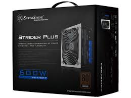
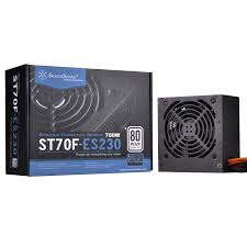
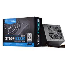
- Power supply installation (for new system assembly)
- Power supply usage notes and caution
- Troubleshooting
- Power supply connectors
- EPS 24-pin motherboard power connector
- ATX 20-pin motherboard power connector
- EPS 8-pin CPU +12V power connector
- ATX 4-pin CPU +12V power connector
- PCI-E 6-pin power connector
- PCI-E 8 pin power connector
- SATA hard disk power connector
- Standard 4-pin peripheral power connector
- Small 4-pin floppy power connector
- Converting wire
- Caution:
- Warranty
- EPS 8-pin CPU +12V Strombuchse/Stecker
- ATX 4-pin CPU +12V Strombuchse/Stecker
- PCI-E 6-pin Strombuchse/Stecker
- Small 4-pin Floppy Strombuchse/Stecker
- PykoBODCTBO npOdyKcIN PSU
- YctaHObKa 3JIeKTPoPNTaHnA (JINr 3aMeHbI)
- IpmeuHnI npedocepexeHne nCnoJIb3ObaHnIO 3NeKtpoNTaHnI
- KOHHeKToP nHTaHm MaTepHcKo NJIaTbI
- EPS 24-pin
- KOHHeKTop nIITaHn MaTePNHcKo nIaTbI ATX 20-pin
- KoHneKTop nHTaHnE EPS 8-pin CPU +12V
- KoHneKTop nHTaHnA TX 4-pin CPU +12V
- KoHHeKToP nHTaHnPA PCI-E 6-pin
- KoHHeKTop nHTaHnPAI-C-E 8 pin
- KoHHeKToP nIITaHnJ XeCTKO rO DnCKa SATA
- CtAnDapThbI 4-pin nepuΦepnHbI KOHKeTOp
- NITaHn
- Mahehkyi 4-pin KOHekTop nItaHn r6ko Duska
- 備註
Brand : SILVERSTONE
Model : STRIDER ESSENTIAL ST50F-ES 80PLUS
Category : Computer power supply