
WH-MHF09G3E8 - Heat pump PANASONIC - Free user manual and instructions
Find the device manual for free WH-MHF09G3E8 PANASONIC in PDF.
User questions about WH-MHF09G3E8 PANASONIC
0 question about this device. Answer the ones you know or ask your own.
Ask a new question about this device
Download the instructions for your Heat pump in PDF format for free! Find your manual WH-MHF09G3E8 - PANASONIC and take your electronic device back in hand. On this page are published all the documents necessary for the use of your device. WH-MHF09G3E8 by PANASONIC.
USER MANUAL WH-MHF09G3E8 PANASONIC
Aquarea Air/Water-heatpump – heating and cooling systems
2014
AQUAREA
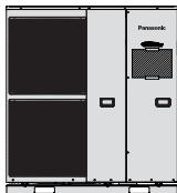
natural_image
Technical line drawing of a Panasonic inverter air conditioning unit (no text or symbols on the diagram itself)
DESIGN HANDBOOK
for Bi-Bloc and Monobloc systems
heiz-undkühlsysteme
Overview of units
| Series | Units | Hydromodule(Indoor unitBi-Bloc) | Outdoor unit(Bi-Bloc orMonobloc) | Operating mode | Nominalheatingcapacity kW | Capacity ofadditional elec-tric heater kW | Single orThree phase |
| Aquarea LT |  | WH-SDF03E3E5* | WH-UD03EE5 | Heating | 3 | 3 | single phase |
| WH-SDC03E3E5* | WH-UD03EE5 | Heating + cooling | 3 | 3 | single phase | ||
| WH-SDF05E3E5* | WH-UD05EE5 | Heating | 5 | 3 | single phase | ||
| WH-SDC05E3E5* | WH-UD05EE5 | Heating + cooling | 5 | 3 | single phase | ||
 | WH-SDC07F3E5* | WH-UD07FE5 | Heating + cooling | 7 | 3 | single phase | |
| WH-SDC09F3E5* | WH-UD09FE5 | Heating + cooling | 9 | 3 | single phase | ||
 | WH-SDC09F3E8* | WH-UD09FE8 | Heating + cooling | 9 | 3 | three phase | |
| WH-SDC12F6E5* | WH-UD12FE5 | Heating + cooling | 12 | 6 | single phase | ||
| WH-SDC12F9E8* | WH-UD12FE8 | Heating + cooling | 12 | 9 | three phase | ||
| WH-SDC14F6E5* | WH-UD14FE5 | Heating + cooling | 14 | 6 | single phase | ||
| WH-SDC14F9E8* | WH-UD14FE8 | Heating + cooling | 14 | 9 | three phase | ||
| WH-SDC16F6E5* | WH-UD16FE5 | Heating + cooling | 16 | 6 | single phase | ||
| WH-SDC16F9E8* | WH-UD16FE8 | Heating + cooling | 16 | 9 | three phase | ||
 | WH-MDC05F3E5* | Heating + cooling | 5 | 3 | single phase | ||
| WH-MDF06E3E5* | Heating | 6 | 3 | single phase | |||
| WH-MDF09E3E5* | Heating | 9 | 3 | single phase | |||
 | WH-MDC09E3E5* | Heating + cooling | 9 | 3 | single phase | ||
| WH-MDF09C3E8 | Heating | 9 | 3 | three phase | |||
| WH-MDC09C3E8 | Heating + cooling | 9 | 3 | three phase | |||
| WH-MDF12C6E5 | Heating | 12 | 6 | single phase | |||
| WH-MDC12C6E5 | Heating + cooling | 12 | 6 | single phase | |||
| WH-MDF12C9E8 | Heating | 12 | 9 | three phase | |||
| WH-MDC12C9E8 | Heating + cooling | 12 | 9 | three phase | |||
| WH-MDF14C6E5 | Heating | 14 | 6 | single phase | |||
| WH-MDC14C6E5 | Heating + cooling | 14 | 6 | single phase | |||
| WH-MDF14C9E8 | Heating | 14 | 9 | three phase | |||
| WH-MDC14C9E8 | Heating + cooling | 14 | 9 | three phase | |||
| WH-MDF16C6E5 | Heating | 16 | 6 | single phase | |||
| WH-MDC16C6E5 | Heating + cooling | 16 | 6 | single phase | |||
| WH-MDF16C9E8 | Heating | 16 | 9 | three phase | |||
| WH-MDC16C9E8 | Heating + cooling | 16 | 9 | three phase | |||
| * Devices have a high efficiency pump and fulfil the criteria of the Ecodesign Directive valid from 2015 for energy-related products (ErP) | |||||||
| AquareaT-CAP | 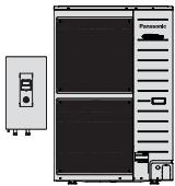 | WH-SXC09F3E5* | WH-UX09FE5 | Heating + cooling | 9 | 3 | single phase |
| WH-SXC09F3E8* | WH-UX09FE8 | Heating + cooling | 9 | 3 | three phase | ||
| WH-SXC12F6E5* | WH-UX12FE5 | Heating + cooling | 12 | 6 | single phase | ||
| WH-SXC12F9E8* | WH-UX12FE8 | Heating + cooling | 12 | 9 | three phase | ||
| WH-SXC16F9E8* | WH-UX16FE8 | Heating + cooling | 16 | 9 | three phase | ||
 | WH-MXF09D3E5 | Heating | 9 | 3 | single phase | ||
| WH-MXC09D3E5 | Heating + cooling | 9 | 3 | single phase | |||
| WH-MXF09D3E8 | Heating | 9 | 3 | three phase | |||
| WH-MXC09D3E8 | Heating + cooling | 9 | 3 | three phase | |||
| WH-MXF12D6E5 | Heating | 12 | 6 | single phase | |||
| WH-MXC12D6E5 | Heating + cooling | 12 | 6 | single phase | |||
| WH-MXF12D9E8 | Heating | 12 | 9 | three phase | |||
| WH-MXC12D9E8 | Heating + cooling | 12 | 9 | three phase | |||
| AquareaHT | 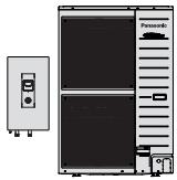 | WH-SHF09F3E5* | WH-UH09FE5 | Heating | 9 | 3 | single phase |
| WH-SHF09F3E8* | WH-UH09FE8 | Heating | 9 | 3 | three phase | ||
| WH-SHF12F6E5* | WH-UH12FE5 | Heating | 12 | 6 | single phase | ||
| WH-SHF12F9E8* | WH-UH12FE8 | Heating | 12 | 9 | three phase | ||
 | WH-MHF09D3E5 | Heating | 9 | 3 | single phase | ||
| WH-MHF09D3E8 | Heating | 9 | 3 | three phase | |||
| WH-MHF12D6E5 | Heating | 12 | 6 | single phase | |||
| WH-MHF12D9E8 | Heating | 12 | 9 | three phase | |||
Overview of all available models and their properties (for explanation of unit names, refer to the “Systematics” section)
Overview of units
Phase-out models C,D & E series
| Series | Units | Hydromodule(Indoor unitBi-Bloc) | Outdoor unit(Bi-Bloc orMonobloc) | Operating mode | Nominalheatingcapacity kW | Capacity ofadditional elec-tric heater kW | Single orThree phase |
| Aquarea LT |  | WH-SDF07C3E5 | WH-UD07CE5 | Heating | 7 | 3 | single phase |
| WH-SDC07C3E5 | WH-UD07CE5 | Heating + cooling | 7 | 3 | single phase | ||
| WH-SDF09C3E5 | WH-UD09CE5 | Heating | 9 | 3 | single phase | ||
| WH-SDC09C3E5 | WH-UD09CE5 | Heating + cooling | 9 | 3 | single phase | ||
 | WH-SDF09C3E8 | WH-UD09CE8 | Heating | 9 | 3 | three phase | |
| WH-SDC09C3E8 | WH-UD09CE8 | Heating + cooling | 9 | 3 | three phase | ||
| WH-SDF12C6E5 | WH-UD12CE5 | Heating | 12 | 6 | single phase | ||
| WH-SDC12C6E5 | WH-UD12CE5 | Heating + cooling | 12 | 6 | single phase | ||
| WH-SDF12C9E8 | WH-UD12CE8 | Heating | 12 | 9 | three phase | ||
| WH-SDC12C9E8 | WH-UD12CE8 | Heating + cooling | 12 | 9 | three phase | ||
| WH-SDF14C6E5 | WH-UD14CE5 | Heating | 14 | 6 | single phase | ||
| WH-SDC14C6E5 | WH-UD14CE5 | Heating + cooling | 14 | 6 | single phase | ||
| WH-SDF14C9E8 | WH-UD14CE8 | Heating | 14 | 9 | three phase | ||
| WH-SDC14C9E8 | WH-UD14CE8 | Heating + cooling | 14 | 9 | three phase | ||
| WH-SDF16C6E5 | WH-UD16CE5 | Heating | 16 | 6 | single phase | ||
| WH-SDC16C6E5 | WH-UD16CE5 | Heating + cooling | 16 | 6 | single phase | ||
| WH-SDF16C9E8 | WH-UD16CE8 | Heating | 16 | 9 | three phase | ||
| WH-SDC16C9E8 | WH-UD16CE8 | Heating + cooling | 16 | 9 | three phase | ||
| * Devices have a high efficiency circulating pump and fulfil the criteria of the Ecodesign Directive valid from 2015 for energy-related products (ErP) | |||||||
Phase-out models C,D & E series
| Series | Units | Hydromodule(Indoor unitBi-Bloc) | Outdoor unit(Bi-Bloc orMonobloc) | Operating mode | Nominalheatingcapacity kW | Capacity ofadditional elec-tric heater kW | Single orThree phase |
| AquareaT-CAP |  | WH-SXF09D3E5 | WH-UX09DE5 | Heating | 9 | 3 | single phase |
| WH-SXC09D3E5 | WH-UX09DE5 | Heating + cooling | 9 | 3 | single phase | ||
| WH-SXF09D3E8* | WH-UX09DE8 | Heating | 9 | 3 | three phase | ||
| WH-SXC09D3E8 | WH-UX09DE8 | Heating + cooling | 9 | 3 | three phase | ||
| WH-SXF12D6E5 | WH-UX12DE5 | Heating | 12 | 6 | single phase | ||
| WH-SXC12D6E5 | WH-UX12DE5 | Heating + cooling | 12 | 6 | single phase | ||
| WH-SXF12D9E8* | WH-UX12DE8 | Heating | 12 | 9 | three phase | ||
| WH-SXC12D9E8 | WH-UX12DE8 | Heating + cooling | 12 | 9 | three phase | ||
| AquareaHT |  | WH-SHF09D3E5 | WH-UH09DE5 | Heating | 9 | 3 | single phase |
 | WH-SHF09D3E8 | WH-UH09DE8 | Heating | 9 | 3 | three phase | |
| WH-SHF12D6E5 | WH-UH12DE5 | Heating | 12 | 6 | single phase | ||
| WH-SHF12D9E8 | WH-UH12DE8 | Heating | 12 | 9 | three phase |
Overview of all available models and their properties (for explanation of unit names, refer to the “Systematics” section)
Table of contents
1 Introduction 8
1.1 Operating principles of the air / water heat pump 8
1.2 Coefficient of Performance and performance factor 9
1.3 Economical and environmentally friendly 10
2 Heat pump system 12
2.1 Heat source 12
2.2 Heat pump 13
2.2.1 Function and properties 13
2.2.2 Operating mode 13
Series 20
Bi-Bloc and Monobloc system 21
3 Products, functions and technical data 22
3.1 Bi-Bloc system 22
3.1.1 Product features 22
Hydromodule 24
Outdoor unit 27
Technical data 30
3.2 Monobloc system 38
3.2.1 Monobloc unit 40
Technical data 42
3.3 Accessories 44
3.3.1 Hot water tank 44
3.3.2 Extras 53
4 Closed-loop control 54
4.1 Design 54
4.2 Functions 54
4.2.1 Basic functions 54
4.2.2 Further functions 57
4.2.3 Safety functions 58
4.3 Extensions and external interfaces 58
4.3.1 External room thermostat 58
4.3.2 Deactivation of heating circuits in cooling mode 59
4.3.3 External control of the Aquarea heat pump 59
4.3.4 External solar thermal installation 60
4.3.5 Aquarea Heat Pump Manager 61
4.3.6 “Smart Grid” function via the Heat Pump Manager 63
5 Project Design 66
5.1 Design steps 66
5.2 Panasonic Aquarea Designer 66
5.3 Establishing the heating load and outside design temperature 67
5.4 Sizing the Hot Water Cylinder 69
5.5 Establishing the heat emitter temperatures 71
5.6 Operating mode and bivalence point 72
5.7 Heat pump selection 73
5.7.1 General criteria 73
5.7.2 What capacity is needed? 73
5.8 Planning of installation room 76
5.8.1 Room volume for bi-bloc system 77
5.8.2 Assembly conditions and minimum distances from hydromodule 77
5.9 Planning heat source – air 79
5.9.1 Bi-Bloc system 79
Capacity decrease in long refrigerant pipe runs 80
Assembly conditions and minimum distances around outdoor unit 80
Fastening of the outdoor unit 81
5.9.2 Monobloc system 82
Assembly conditions and minimum distances from monobloc unit 83
Fastening of the monobloc unit 84
5.10 Acoustics 85
5.10.1 Sound pressure level 85
5.10.2 Sound power levels for estimation of sound pressure level 86
5.11 Cooling 89
5.11.1 Cooling with underfloor heating 89
5.11.2 Cooling with fan convectors 89
5.12 Electrical connection 90
5.12.1 Power supply 90
5.12.2 Connections to the inputs and outputs 93
5.12.3 DNO and tariffs 94
5.13 Hydraulics 94
5.13.1 Hydraulic integration 94
Hydraulic decoupling for standard pumps and high-efficiency pumps
without differential pressure control 95
Hydraulic decoupling for high-efficiency pumps with differential pressure control ..... 95
Inline/Strainer filter 96
Magnetic Particle Filter 96
System volume 96
5.13.2 Pumping height and pipe network resistance 97
5.13.3 Pumping height 99
5.13.4 Hydraulic balancing 101
5.13.5 Special behaviour when cooling 101
5.13.6 Expansion vessel 102
5.13.7 Heating water quality 103
5.13.8 Use of buffer tanks 103
6 Examples 104
6.1 Legend 104
Examples 1 to 10 105–114
7 Appendix 115
1 Introduction
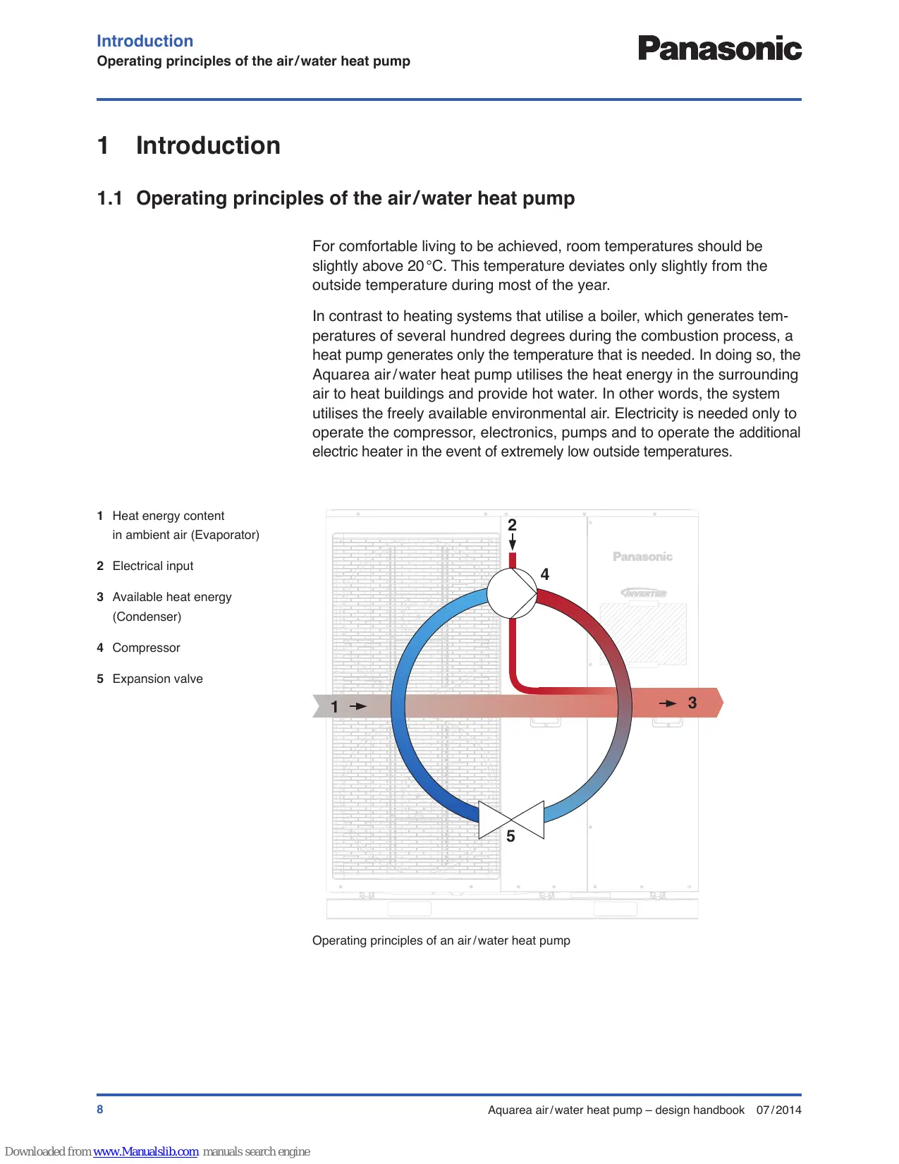
1.1 Operating principles of the air/water heat pump
For comfortable living to be achieved, room temperatures should be slightly above 20^ C. This temperature deviates only slightly from the outside temperature during most of the year.
In contrast to heating systems that utilise a boiler, which generates temperatures of several hundred degrees during the combustion process, a heat pump generates only the temperature that is needed. In doing so, the Aquarea air/water heat pump utilises the heat energy in the surrounding air to heat buildings and provide hot water. In other words, the system utilises the freely available environmental air. Electricity is needed only to operate the compressor, electronics, pumps and to operate the additional electric heater in the event of extremely low outside temperatures.
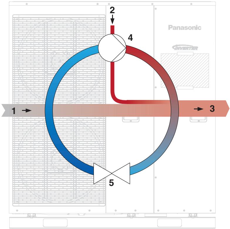
1 Heat energy content in ambient air (Evaporator)
2 Electrical input
3 Available heat energy (Condenser)
4 Compressor
5 Expansion valve
flowchart
graph TD
    A["Central Node"] --> B["Component 1"]
    A --> C["Component 2"]
    A --> D["Component 3"]
    A --> E["Component 4"]
    A --> F["Component 5"]
    style A fill:#f9f,stroke:#333
    style B fill:#bbf,stroke:#333
    style C fill:#bfb,stroke:#333
    style D fill:#ffb,stroke:#333
    style E fill:#ffb,stroke:#333
    style F fill:#ffb,stroke:#333
Operating principles of an air/water heat pump
Ambient heat is brought up to a higher temperature level in a cyclical process. To do this, an environmentally compatible refrigerant undergoes four steps:
- The refrigerant boils inside the evaporator where it is transformed from a liquid into the gas state. During this step, heat is extracted from the surrounding air (figure 1 on the previous page).
- Inside the compressor the pressure of the gaseous refrigerant is greatly increased. The temperature increases accordingly. This step occurs with the supply of electric energy (figure 2 on the previous page).
- In the condenser, the gaseous refrigerant condenses and dissipates the latent heat of condensation to the heating water, whereby it cools down at the same time (figure 3 on the previous page).
- The pressure of the liquid coolant drops suddenly when it passes through the expansion valve, causing its temperature to drop heavily and thus allowing it to once more absorb heat from the ambient environment (figure 5 on the previous page).
This process is a continuous cycle and can be controlled by the inverter-plus technology of the Aquarea heat pump so that the current heat requirement is catered for.
Reversing the cycle process causes the unit to act like a refrigerator.
This allows Aquarea heat pumps to be used also for air conditioning.
1.2 Coefficient of Performance and performance factor
The Coefficient of Performance (COP) of a heat pump is defined as the ratio of heat power output to the electrical power input and says something about the efficiency of the heat pump at a certain moment. Depending upon the outside temperature and the temperature of the generated heat, the COP of heat pumps will differ. It is generally the case that the coefficient of performance decreases in proportion with an increasing temperature difference between the outside temperature and the temperature of the heat generated. A comparison of the efficiency of different heat pumps is only possible at the same temperatures. COPs for air/water heat pumps are normally measured at the following temperatures:
| Outside temperature | Output flow temperature |
| A-15 | W35 |
| A-7 | W35 |
| A7 | W35 |
| A2 | W55 |
(A stands for Air, W stands for Water)
Example
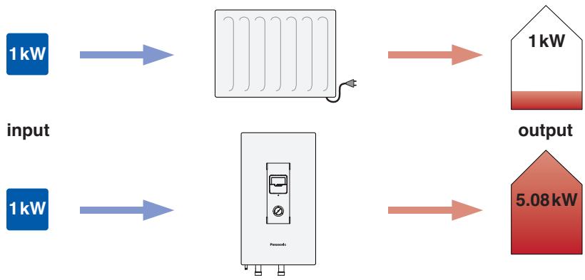
Coefficient of performance = 5.08 (A7/W35)
For an outside temperature of 7^ C the air/water heat pump produces hot water at 35^ C at a COP of 5.08. Thus, 5.08 kilowatt-hours of heat energy can be generated from one kilowatt-hour of electrical energy.
Performance factor is more meaningful than the COP, which represents the ratio of heat energy output to the electrical energy input over a certain period. The seasonal performance factor (SPF) is the ratio of heat energy output to the electrical energy input over a one year period. It is obtained from heat and electricity meters and includes all aspects of the heat pump system.
Similar to the coefficient of performance for the heating operation, the coefficient of performance for the cooling operation is defined as the ratio of heat power removed to the electrical power input. In contrast to COP, it is abbreviated with EER = energy efficiency ratio.
1.3 Economical and environmentally friendly
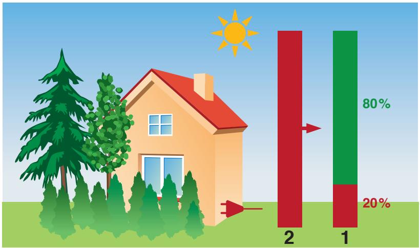
More than 75% of energy use in the household is used for heating and hot water. At the same time fuel prices (oil, gas, wood pellets) are subject to strong price fluctuations and are becoming increasingly more expensive.
In contrast, an Aquarea heat pump utilises up to 80% free ambient heat can be used. Electrical energy must be used only for the remaining 20% of the heat pump operation. In comparison with a direct electric heater, the amount of electrical energy used for the same heat production is reduced down to a quarter.
In comparison with fossil fuel based heating systems, the dependence on oil price and risky energy imports is therefore reduced. In addition, the share of renewable energy in electricity production today is already about 25% in the UK and expected to rise. Besides the ambient heat, the electric energy used for heat pumps is increasingly derived from renewable energy sources.
Besides low electricity use, a yearly oil or gas service is no longer required. Additionally, the investment costs for an Aquarea air/water heat pump are proportionally lower in comparison to other heating systems with natural gas connection, chimney, oil tank or boreholes.
Aquarea heat pumps can optionally be operated also with cooling function and supplemented with a solar system. This allows comfort and efficiency to be increased further.
bar
| Category | Value (%) | |---|---| | 1 | 80 | | 2 | 20 |1 Aquarea heat pump
2 Conventional electric heating
flowchart
graph LR
    A["1kW input"] --> B["Reactor with fan"]
    C["1kW output"] --> D["House with roof"]
    E["1kW input"] --> F["Pump meter"]
    G["output"] --> H["5.08kW output"]
Comparison of power consumption of an Aquarea heat pump to a direct electric heater for the same electricity input
Air to water heat pump heating installations can receive financial support via the UK Domestic Renewable Heat Incentive (dRHI) and the non-domestic RHI. Current tariff rates can be found at www.ofgem.gov.uk. For equipment of less than 45 kW, it is also a requirement of these schemes that both equipment and installer be accredited with the Microgeneration Certification Scheme (MCS) – www.microgenerationcertification.org

Note
Panasonic offers a free program for sizing heat pumps with which the seasonal performance factor can be calculated according to VDI 4650, the Aquarea Designer (see the “Panasonic Aquarea Designer” section in the planning chapter).
Please see www.microgenerationcertification.org for details of how to apply for MCS accreditation.
2 Heat pump system
1 Heat source ambient air
2 Heat pump
Bi-Bloc or Monobloc unit
3 Heat utilisation
Water heating
Heating
Cooling
Smooth and efficient operation of the heat pump system requires careful design and consideration of all aspects of the system from the heat source up to the heat utilisation.
2.1 Heat source
Air as a heat source is available everywhere and can be utilised without limit by means of an air-heat exchanger in combination with fans at very low expense. However, the outside temperature fluctuates significantly in the course of the year and is inversely proportional to the heat requirement. This means that the most heat must be generated when the heat source is at its coldest state. This must be accounted for during the planning phase so that the required internal temperatures are always achieved.
Likewise the noise of the fans and air flow must be considered by ensuring minimum distances from neighbouring plots as well as by selecting a suitable installation location.
2.2 Heat pump
2.2.1 Function and properties
The heat pump as the core piece of the heat pump system was developed by Panasonic in three different series. In this manner, individual requirements for the heat supply of buildings should be considered with each series' properties in mind:
Aquarea LT

Ideal for low-temperature heat emitters or underfloor heating systems; also for radiators.
Aquarea HT

For high temperature radiators (e.g. radiators in the refurbishment context), Aquarea HT can supply a water temperature of 65^ C without assistance even at outside temperatures of -15^ C.
Aquarea T-CAP

For applications at which the kW output capacity should be kept constant even at outside temperatures of -7 or -15^ . It is ensured that even under extremely low outside temperatures sufficient capacity is always at disposal for heating the house without assistance from other heat generators.
With the exception of the HT series, all models are available with cooling mode. Furthermore, Aquarea heat pumps are available in 2 version: Monobloc (the whole unit outdoors) or Bi-Bloc (indoor and outdoor unit) (for details see the chapter 3).
2.2.2 Operating mode
It is generally true that the larger the difference between outside temperature and the temperature of the generated heat, the lower the performance factor of the heat pump. Since high temperature differences occur extremely rarely with correctly designed heat pump systems in the course of the year, temporary heating with an additional electric heater is often accepted. Alternatively to an additional electric heater, it is possible to work with an alternative heat generator like a condensing boiler or a stove with a back boiler. The four different operating modes are:
1. Monovalent operating mode
Heat pump serves as the sole heat generator.
2. Mono-energetic operating mode
Electricity is used to operate a heat pump and additional electrical heater (electric heat pump + additional electric heater for peak load).
3. Bivalent alternative operating mode
A second heat generator supplies the property using a further energy source, under certain conditions (e.g. stove with back boiler instead of heat pump for outside temperatures < -5^ ).
4. Bivalent parallel operating mode
Besides the heat pump, a second heat generator is used using a further energy source. Both heat generators are operated simultaneously (e.g. heat pump + condensing boiler for outside temperatures <0^ ).

Note
When the heat pump is operated in connection with an additional electric heater in mono-energetic mode, the additional electric heater should cover a maximum of 15% of the heat requirement.
If your system must comply with the UK Microgeneration Certification Scheme's MIS 3005 document, an additional electric heater should be only designed to operate for space heating for the coldest 1% of the year.
In contrast to heat generators such as boilers that produce water supply temperatures of over 80^ C, the maximum water supply temperature of the Aquarea heat pump is limited at 55^ C or 65^ C for Aquarea HT. This must be accounted for during the designing of heat emitter circuits. Underfloor heating is ideal with a heat pump as the floor is a large emitter area and therefore you can use a low temperature to heat the room.
Fan convectors have the advantage of good heat dissipation to the indoor air and are easily controllable, with the advantage of using a lower temperature than standard radiators to heat the room. At the same time they can be used for either heating or cooling operation.
When radiators are used, they should be planned likewise with a low design temperature of e.g. 45^ C in order to ensure a high efficiency of the heat pump system. An additional electric heater of 3 to 9 kW caters for sustained heating comfort even under very low outside temperatures, due to the mono-energetic mode. A bivalent operation in combination with an external heater is a possible alternative.
The Aquarea heat pump is provided with an outside temperature dependent control of the supply water temperature and can activate a heating circuit in connection with a room thermostat. The control of further heating circuits can occur via an additional heating circuit controller or an overriding system controller on site.

Note
To comply with UK subsidy requirements for sub-45 kW appliances, the document “Heat Emitter Guide” should also be consulted: www.microgenerationcertification.org
2.3.2 Water heating
The Aquarea heat pump has a water heating operation integrated within the control system. Upon demand, the water heating operation is switched on and heats the hot water tank via a 3-way directional valve.
Since the required temperature for water heating in general lies above the temperature of the heating operation over the year, the coefficient of performance (COP) is low in the water heating mode in comparison to the heating mode. For efficiency reasons, the hot water storage temperature is therefore set below 60^ C. A hot water temperature of 45 to 50^ C is sufficient for normal applications and is not at all connected with reduced comfort. However with lower stored temperatures, attention must be paid to the danger of legionella which especially thrive within the range 30 to 45^ C.
The Panasonic hot water cylinders are equipped with an electric immersion heater which can be activated for legionella control, on a periodic timer basis.
Aquarea heat pumps can be combined easily with solar thermal installations, which can largely take over water heating in the summer months.

Note
The requirements for the control of legionella propagation in the workplace are described in HSE guide L8

Attention
When using the Panasonic hot water tank, the quality of water must comply with the potable water directive 98/83/EC. When the chloride and sulphate content exceeds 250 mg/l, water treatment is required. For values above 250 mg/l the guarantee expires.
Water regulations must be considered at all times when installing an Aquarea heat pump.
2.3.3 Cooling
Depending on the product series, the cooling mode can be manually switched via the control panel/remote control or is automatically switched at defined temperature points. Depending on the product series, switching over to heating mode occurs manually at the end of the cooling period or automatically at the defined temperature thresholds.
Room cooling is possible by means of radiant panels such as underfloor, wall or ceiling cooling systems or particularly via fan convectors. Individual heating circuits that are not suitable for the cooling operation can be deactivated by a control system via a 2-way directional valve. For all transfer systems, it is possible for the temperature to fall below the dew point, which can result in condensation in the cooling mode, with high relative humidity. This must be ruled out particularly with radiant panels, via a dew-point sensor, the supply water temperature must be raised through mixing with the return flow, or the cooling mode must be switched off in an emergency. Fan convectors can be operated with much lower supply water temperatures in comparison to radiant panels in the cooling mode and therefore have greater cooling capacities. However, fan convectors for the cooling mode must always be provided with a condensate drain and piping with closed-cell insulation.

Attention
In the cooling mode, condensation of moisture in the air can occur on the surface of the heat transfer systems when the temperature falls below the dew point. This can lead to damage to the building or to the danger of slipping on floor surfaces.
The temperature falling below the dew point must therefore be avoided by means of suitably placed dew point sensors or the condensate occurring must be drained safely. The affected piping must be insulated fully against this condensation risk.
2.4 Systematics and overview
2.4.1 Systematics
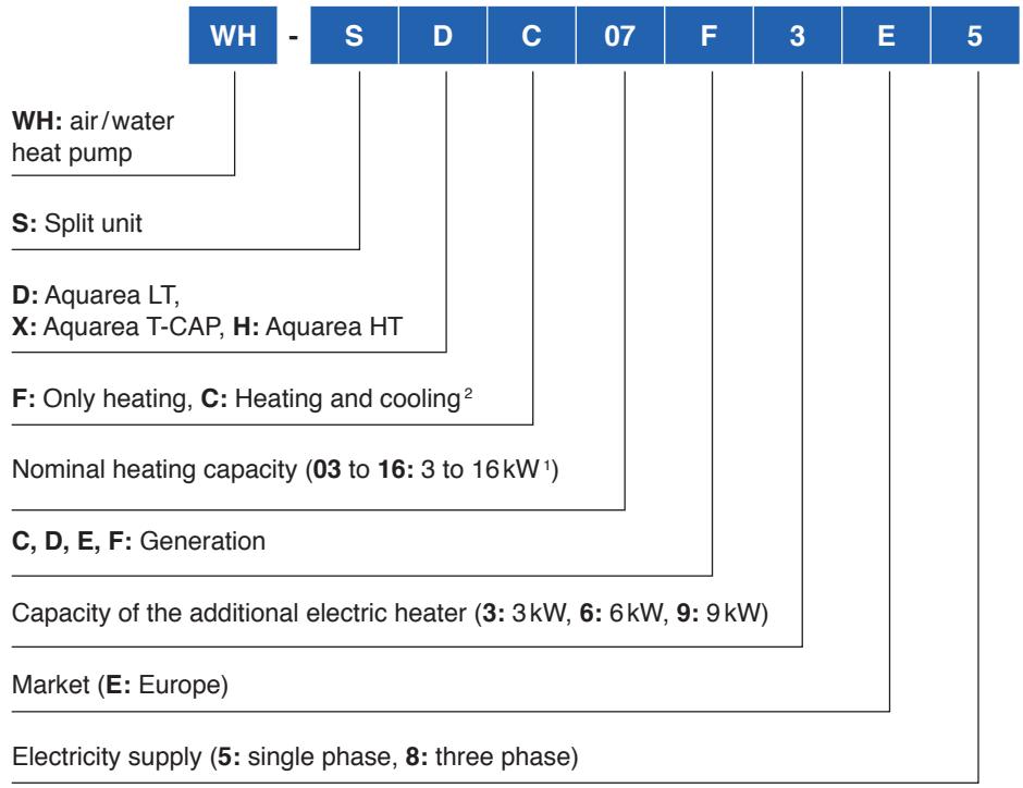
For easy and clear categorisation of different Aquarea models, a key is used, from which the models with their respective specific properties and functions can be read.
Example
The WH-MDC05F3E5 is a compact heat pump unit (M), in the LT series (D), with a cooling function (C), a rated power of 5 kW (05), of the generation F (F), for the European market (E), with a single-phase voltage supply (5).
Systematics of hyrdomodule (Indoore unit Bi-Bloc)
flowchart
graph TD
    A["WH - S D C 07 F 3 E 5"] --> B["WH: air/water heat pump"]
    B --> C["S: Split unit"]
    C --> D["D: Aquarea LT, X: Aquarea T-CAP, H: Aquarea HT"]
    D --> E["F: Only heating, C: Heating and cooling²"]
    E --> F["Nominal heating capacity (03 to 16: 3 to 16kW¹)"]
    F --> G["C, D, E, F: Generation"]
    G --> H["Capacity of the additional electric heater (3: 3kW, 6: 6kW, 9: 9kW)"]
    H --> I["Market (E: Europe)"]
    I --> J["Electricity supply (5: single phase, 8: three phase)"]
^1 The available power classes differ depending on the respective series.
The table at the start of the document provides an overview of the power classes for each individual series.
^2 The units of the Aquarea HT series can only be used for heating mode and do not have a cooling mode.
Systematics of outdoor unit (Bi-Bloc)
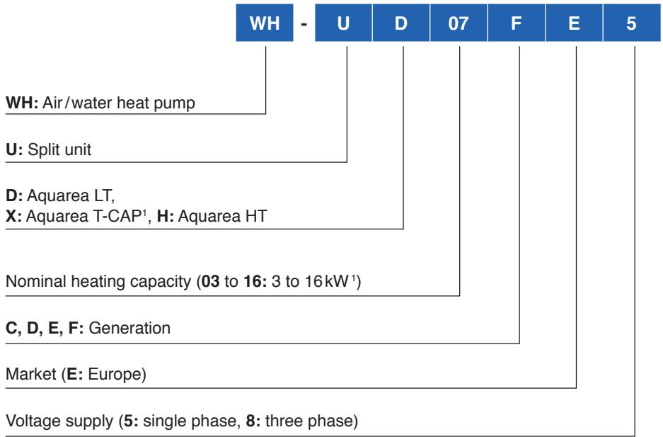
flowchart
graph TD
    A["Voltage supply (5: single phase, 8: three phase)"] --> B["Market (E: Europe)"]
    B --> C["C, D, E, F: Generation"]
    C --> D["Nominal heating capacity (03 to 16: 3 to 16kW¹)"]
    D --> E["D: Aquarea LT, X: Aquarea T-CAP¹, H: Aquarea HT"]
    E --> F["U: Split unit"]
    F --> G["WH: Air/water heat pump"]
    G --> H["WH - U D 07 F E 5"]
Systematics of monobloc unit
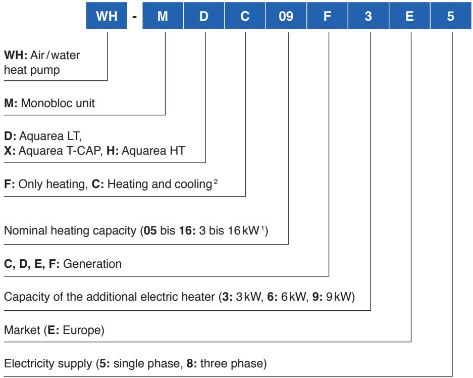
flowchart
graph TD
    A["WH - M D C 09 F 3 E 5"] --> B["WH: Air/water heat pump"]
    A --> C["M: Monobloc unit"]
    A --> D["D: Aquarea LT, X: Aquarea T-CAP, H: Aquarea HT"]
    A --> E["F: Only heating, C: Heating and cooling²"]
    A --> F["Nominal heating capacity (05 bis 16: 3 bis 16 kW¹)"]
    A --> G["C, D, E, F: Generation"]
    A --> H["Capacity of the additional electric heater (3: 3kW, 6: 6kW, 9: 9kW)"]
    A --> I["Market (E: Europe)"]
    A --> J["Electricity supply (5: single phase, 8: three phase)"]
2.4.2 Overview
The Aquarea heat pump system has three different series which are again available in several model variants. This allows the best possible consideration of the individual heating requirements and climate control requirements of buildings with Aquarea heat pumps.
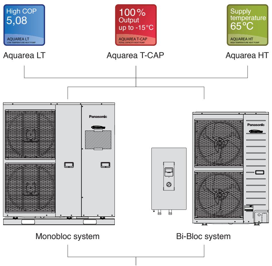
flowchart
graph TD
    A["Aquarea LT"] --> B["Monobloc system"]
    C["Aquarea T-CAP"] --> D["Bi-Bloc system"]
    E["Aquarea HT"] --> F["Bi-Bloc system"]
    G["High COP 5,08"] --> H["Aquarea LT"]
    I["100% Output up to -15°C"] --> J["Aquarea T-CAP TOTAL CAPACITY HEAT PUMP"]
    K["Supply temperature 65°C"] --> L["Aquarea HT HIGH TEMPERATURE HEAT PUMP"]
    M["Panasonic"] --> N["Panasonic"]
• Heating and cooling or heating
- Nominal heating capacity (3, 5, 6, 7, 9, 12, 14 or 16 kW)
- Capacity of additional electric heater (3, 6 or 9 kW)
• Electric connection (single phase or three phase)
Overview of series and model variants
The variety of properties and functions of the Aquarea heat pumps leads to a large number of different model variants, which often only differ from one another through small differences like the capacity of the additional electric heater. Externally viewed, the units are nearly similar apart from distinctive differences like the monobloc or bi-bloc system and they can therefore be described together with regard to many properties. Relevant differences are pinpointed at an appropriate point.
The Aquarea heat pump models are configured so that a suitable model is available for all typical applications. All models are listed with their properties and functions in the table at the beginning of the Design Handbook.
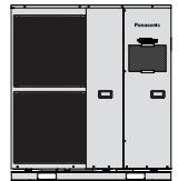
As shown in the overview tables the available systems differ externally, especially between the monobloc systems and bi-bloc systems, and the units are equipped with one or two fans depending on the rated power.
Series
The Aquarea series differ through their maximum supply water temperature and capacity stability at very low outside temperatures as follows:
Aquarea LT
Maximum supply water temperature: 55°C
Capacity at very low outside temperatures: kW heating capacity varies
Aquarea T-CAP
Maximum supply water temperature: 55°C
Capacity at very low outside temperatures: Heating capacity is constant up to -15^ at 35^ output water temperature
Aquarea HT
Maximum supply water temperature: 65°C
Capacity at very low outside temperatures: Heating capacity is constant up to -15^ at 35^ output water temperature
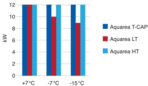
bar
| Temperature | Aquarea T-CAP (kW) | Aquarea LT (kW) | Aquarea HT (kW) | | :--- | :--- | :--- | :--- | | +7°C | 12 | 12 | 12 | | -7°C | 12 | 10 | 12 | | -15°C | 12 | 9 | 12 |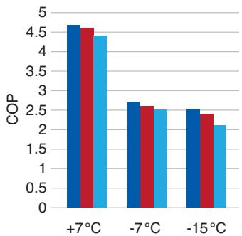
bar
| Temperature | COP | | ----------- | ---- | | +7°C | 4.6 | | -7°C | 2.7 | | -15°C | 2.5 |Heating capacity and coefficient of performance (COP) of the Aquarea LT Aquarea T-CAP and Aquarea HT series with 12 kW at different outside temperatures and a supply water temperature of 35 °C and a return water temperature of 30 °C.
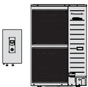
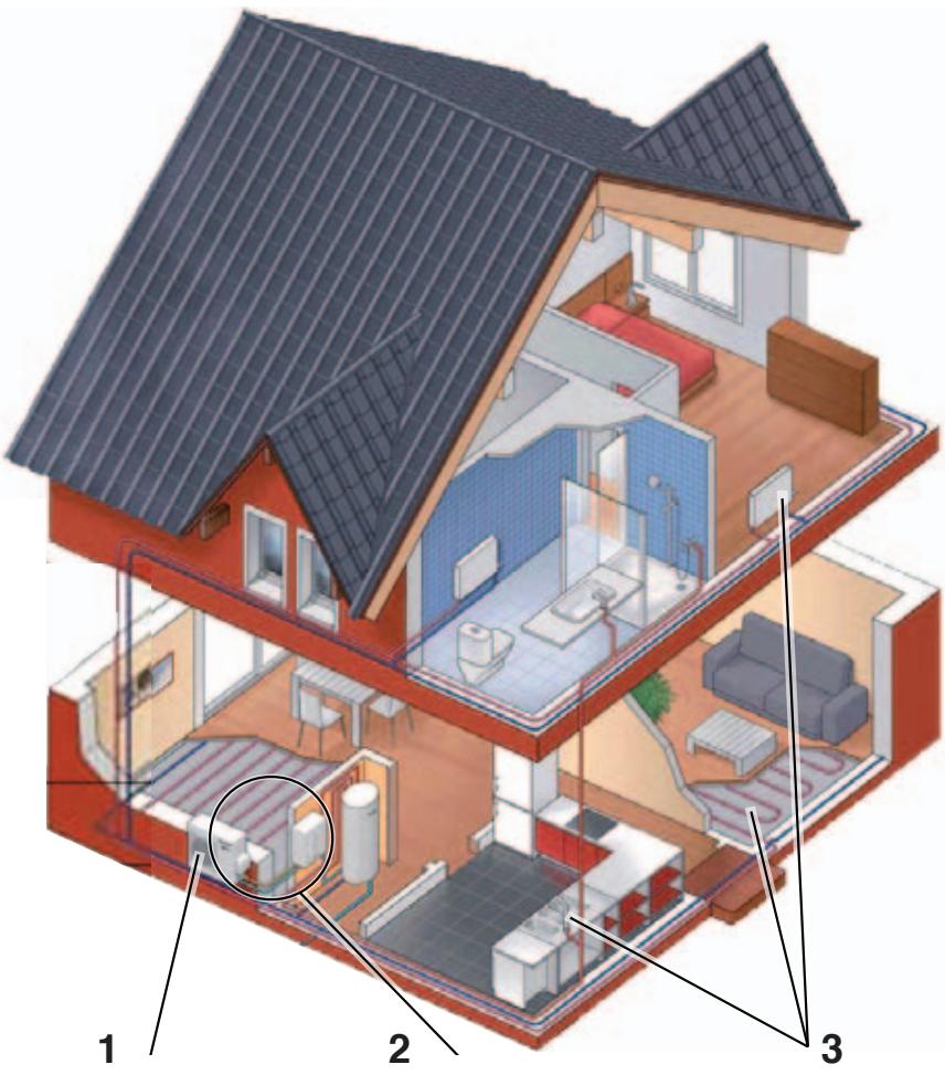
Bi-Bloc and Monobloc system
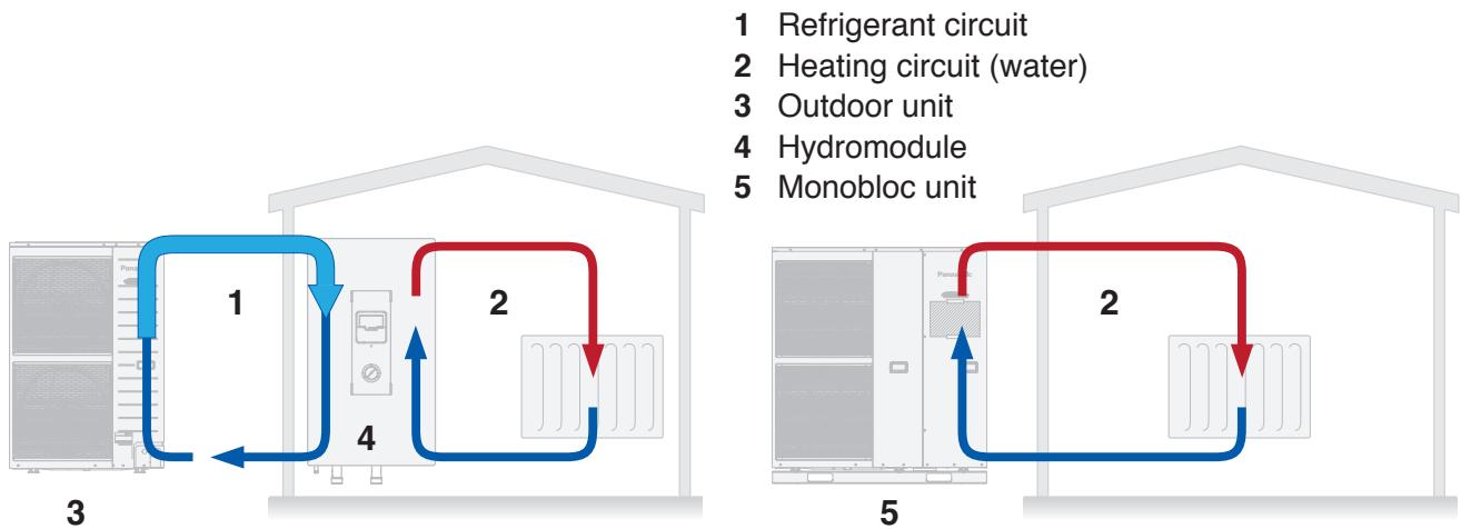
1 Refrigerant circuit
2 Heating circuit (water)
3 Outdoor unit
4 Hydromodule
5 Monobloc unit
Difference between Bi-Bloc system (left) and monobloc system (right)
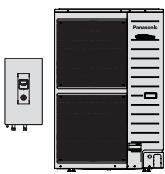
Bi-Bloc system
The bi-bloc system consists of a freely installed outdoor unit and a hydromodule that is normally installed in the installation room or in a different frost-free room. In the case of this design, the two units are connected by means of refrigerant piping, in which there is no danger of freezing. The heat pump is controlled by means of the controller on the hydromodule.
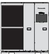
Monobloc system
The Monobloc system consists of only one unit that is installed outdoors. Refrigerant piping is not required for the installation, it is connected directly to the heating system. Monobloc systems are easy to install, but need more space. Moreover, the water within the heating system is in danger of freezing due to power failure or when the power supplier cuts off the supply.
The heat pump is operated via a wired remote control that is mounted inside the building and is connected to the Monobloc unit by means of a 15-metre long cable.

Attention
The Monobloc system is in danger of freezing when the heating circuit is filled with water and the outside temperature decreases below +4 °C! This can lead to substantial damage to the unit.
Freedom from frost must be ensured within the heating system through one of the following options:
- The heating circuit is operated with a foodgrade frost protection mixture (propylene glycol).
- An auxiliary electric heater inside the Monobloc unit prevents the heating circuit from freezing.
- The heating circuit is emptied via an owner-provided device (manually or automatically).
3 Products, functions and technical data
3.1 Bi-Bloc system
Specific hydromodules and outdoor units are supplied together as a set, as each set is fine tuned to work together. Different hydromodules and outdoor units can not thus be combined arbitrarily. The Aquarea Bi-Bloc system consists of the hydromodule (indoor) and an outdoor unit. For all typical applications a suitable Aquarea Bi-Bloc system model consisting of hydro-module and outdoor unit is available.
3.1.1 Product features
Energy efficiency and environmental friendliness
- up to 80% energy extraction from ambient air for a greater energy efficiency
• maximum COP of 5.00 for single phase 3 kW model for A7/W35 - inverter technology allows controllable output of the unit and contributes to energy saving
- environmentally compatible refrigerant (R410A with Aquarea LT and T-CAP and R407C with Aquarea HT), does no damage to the ozone layer
- All units from generation E onwards are equipped with high-efficiency pumps
High level of comfort
- optimum control by means of room thermostats (room thermostats not supplied)
- models for heating mode as well as heating and cooling mode are available
- optimised capacity depending on the return water temperature
- integrated control of the hot water tank and heating system
• 24-hour timer with operating mode control
Easy operation
• operation and control on the hydromodule
- simple programming via the controller
- Aquarea hydromodule is equipped for safety reasons with:
- 2 FI RCD circuit breakers with 3, 5, 7, 9, 12, 14 and 16kW units
- 3 FI RCD circuit breakers with 12, 14 and 16kW units (Phase-out models)
Easy maintenance and assembly
- compact design
- easy control of the water pressure through a gauge in the front casing
- easy to open - hydromodule and outdoor unit
- flexible assembly due to long piping
- piping up to 30 metres with a height difference up to 20 metres (for models up to 9 kW)
- piping up to 40 metres with a height difference of up to 30 metres (for models with 12 to 16 kW)
- the piping connection to the outdoor units can occur in four directions (front, rear, side, bottom)
| Supply water temperature (°C) | Outside temperature (°C) | ||
| Cooling mode1 | Maximum | 20 | 43 |
| Minimum | 5 | 16 | |
| Heating mode | Maximum | 55/65^2 | 35 |
| Minimum | 25 | -203 | |
^1 valid for models with cooling mode
^2 valid for Aquarea HT
^3 If the outside temperatures drop below the specified value, the heating capacity decreases significantly. This can lead to the shutdown of the unit due to internal safety functions.
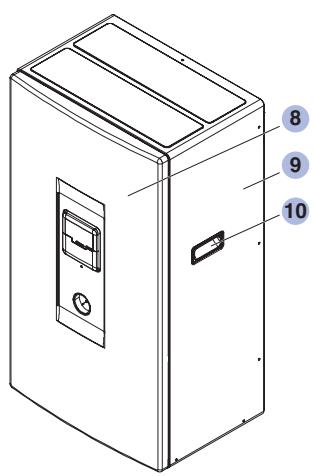
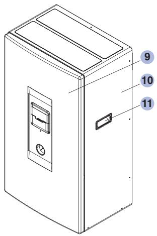
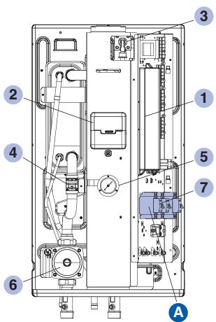
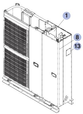
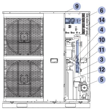
Hydromodule
Components
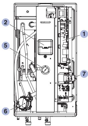
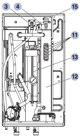
Component name
1 Electronic printed circuit board
2 Controller
3 Safety valve
4 Flow rate cut-out
5 Manometer (water pressure gauge)
6 Water circulation pump
(Illustration shows a high-efficiency pump without differential pressure control)
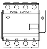
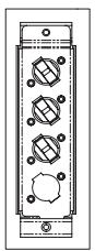
7 FI RCD circuit breakers (differs from model to model, see Detail A)
8 Cabinet front plate
9 Cabinet
10 Handle
11 Overload protection
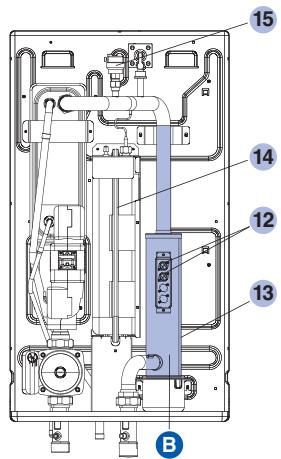
12 Additional electric heater
13 10L Expansion vessel
14 Cable passage
15 Deaeration
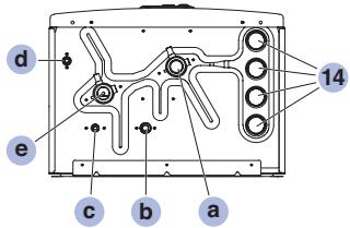
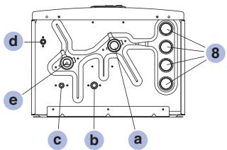
Connection name
a Supply water ∅ R 1¼
b Gas side refrigerant connection (19.1 mm)
c Liquid side refrigerant connection (6.4 to 9.5 mm)
d Water drain
e Supply water ∅ R 1¼
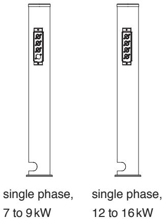
A Different FI RCD circuit breakers
single phase 3 to 5 kW
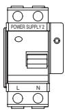
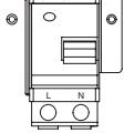
three phase 9kW
©
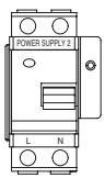
single phase 7 to 16kW
three phase 12 to 16kW

Hydromodule
Phase-out models C & D series
Components
Component name
1 Electronic printed circuit board
2 Controller
3 Safety valve
4 Flow rate cut-out
5 Manometer (water pressure gauge)
6 3-stage water circulation pump (Figure shows standard pump)
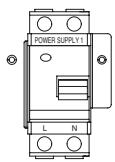
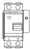
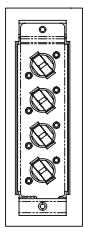
7 FI RCD circuit breakers (differs from model to model, see Detail A)
8 Cable passage
9 Cabinet front plate
10 Cabinet
11 Handle
12 Overload protection (differs from one model to the other, see Detail B)
13 Additional electric heater (3, 6 and/or 9 kW)
14 10I Expansion vessel
15 Deaeration
Connection name
a Supply water ∅ R 1¼
b Gas side refrigerant connection (19.1 mm)
c Liquid side refrigerant connection (6.4 to 9.5 mm)
d Water drain
e Supply water ∅ R 1¼
A Different FI RCD circuit breakers
single and three phase, 3 to 9 kW
single and three phase, 12 to 16kW


B Different electric heating and overload protection elements
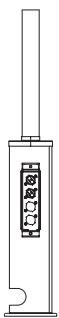
three phase, 12 to 16 kW and single phase 3 to 5 kW
Detail A (left) and B (right) of the components of hydromodule
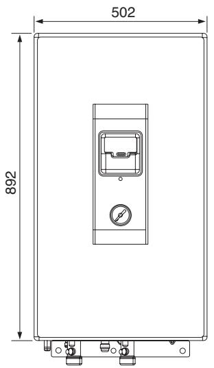
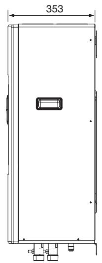
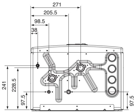
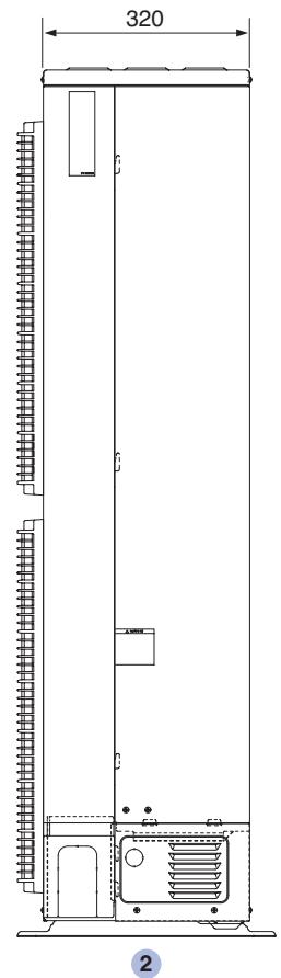
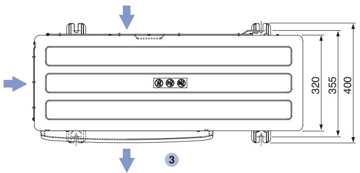
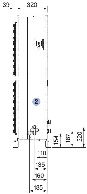
Dimensional drawing for hydromodule
1 Front view
2 Side view
3 Bottom view
1
2
3
Dimensions of hydromodule in mm
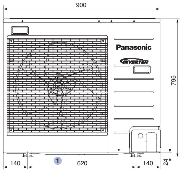
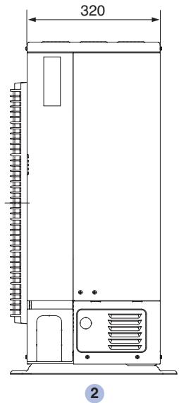
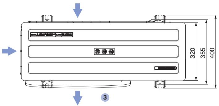
Outdoor unit
Dimensional drawing for outdoor unit with one fan (3 and 5 kW)
1 Front view
2 Side view
3 Bottom view
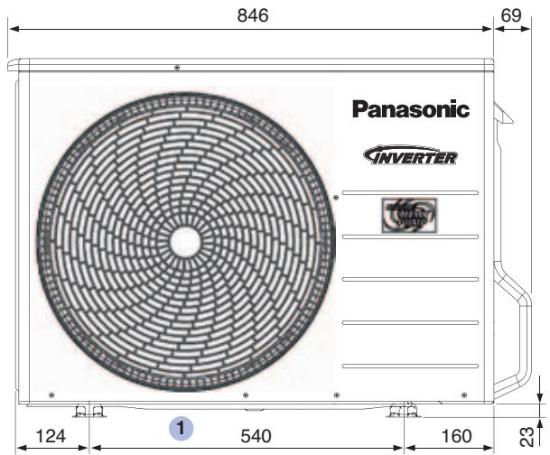
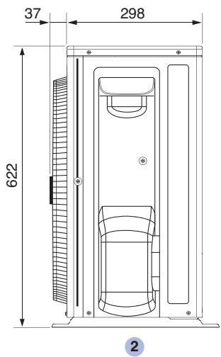
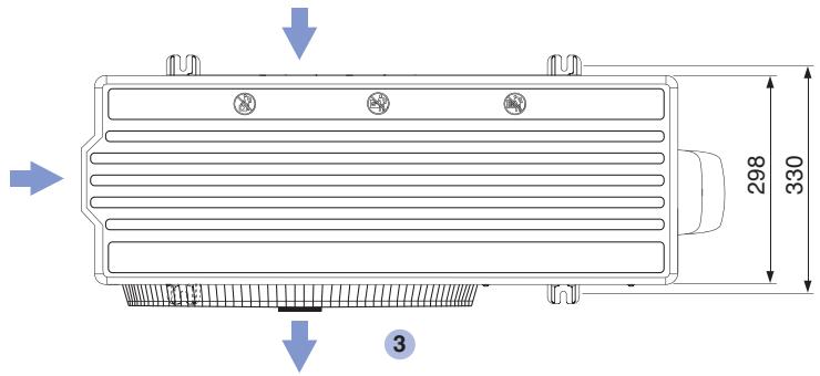
Dimensions of outdoor unit with one fan (3 and 5 kW) in mm. The air flow is depicted by arrows.
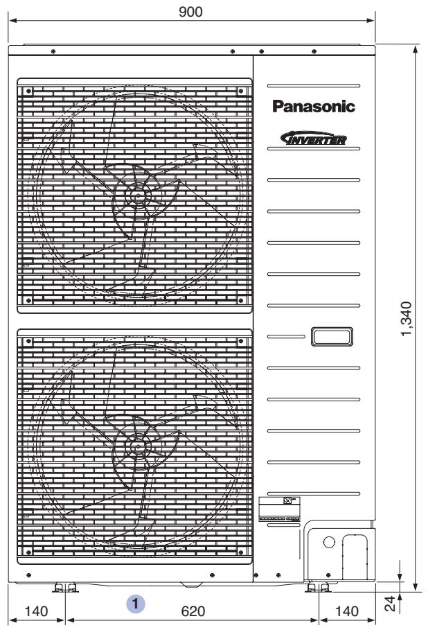
Outdoor unit
Dimensional drawing for outdoor unit with one fan (7 and 9 kW)
1 Front view
2 Side view
3 Top view
Dimensions of outdoor unit with one fan (7 and 9 kW) in mm.
The air flow is depicted by arrows.
Dimensional drawing for outdoor unit with two fans
1 Front view
2 Side view
3 Top view
Dimensions of outdoor unit with two fans in mm. The air flow is depicted by arrows.
| Bi-Bloc system | Series | Aquarea LT | ||||||||||
| Phases | single phase | |||||||||||
| Hydromodule | Model | WH-SDF03E3E5* | WH-SDC03E3E5* | WH-SDF05E3E5* | WH-SDC05E3E5* | WH-SDC07F3E5*1 | WH-SDC09F3E5*1 | WH-SDC12F6E5*1 | WH-SDC14F6E5*1 | WH-SDC16F6E5*1 | ||
| Output capacity | Heating capacity A-15/W35 | kW | 3.2 | 4.2 | 4.29 | 5.9 | 9 | 9.73 | 10.24 | |||
| Power consumption A-15/W35 | kW | 1.39 | 1.94 | 1.88 | 2.5 | 3.55 | 3.9 | 4.24 | ||||
| Coefficient of performance A-15/W35 | - | 2.3 | 2.16 | 2.28 | 2.36 | 2.54 | 2.49 | 2.42 | ||||
| Heating capacity A-7/W35 | kW | 3.2 | 4.2 | 5.75 | 6.55 | 10.74 | 11.55 | 12.28 | ||||
| Power consumption A-7/W35 | kW | 1.19 | 1.62 | 1.99 | 2.38 | 3.58 | 3.96 | 4.32 | ||||
| Coefficient of performance A-7/W35 | - | 2.69 | 2.59 | 2.89 | 2.75 | 3 | 2.91 | 2.84 | ||||
| Heating capacity A2/W35 | kW | 3.2 | 4.52 | 6.55 | 6.7 | 11.4 | 12.4 | 13 | ||||
| Power consumption A2/W35 | kW | 0.9 | 1.35 | 1.96 | 2.14 | 3.31 | 3.69 | 3.96 | ||||
| Coefficient of performance A2/W35 | - | 3.56 | 3.35 | 3.34 | 3.13 | 3.44 | 3.36 | 3.28 | ||||
| Heating capacity A7/W35 | kW | 3.2 | 5 | 7 | 9 | 12 | 14 | 16 | ||||
| Power consumption A7/W35 | kW | 0.64 | 1.08 | 1.57 | 2.18 | 2.53 | 3.07 | 3.74 | ||||
| Coefficient of performance A7/W35 | - | 5 | 4.63 | 4.46 | 4.13 | 4.74 | 4.56 | 4.28 | ||||
| Heating capacity A2/W55 | kW | 3.2 | 4.1 | 6 | 9.1 | 9.5 | 9.8 | 9.8 | ||||
| Power consumption A2/W55 | kW | 1.49 | 2.07 | 3.16 | 4.18 | 4.4 | 4.55 | 4.55 | ||||
| Coefficient of performance A2/W55 | - | 2.15 | 1.98 | 1.9 | 2.18 | 2.16 | 2.15 | 2.15 | ||||
| Cooling capacity A35/W7 | kW | - | 3.2 | - | 4.5 | 6 | 7 | 10 | 11.5 | 12.2 | ||
| Power consumption A35/W7 | kW | - | 1.04 | - | 1.67 | 2.28 | 2.88 | 3.65 | 4.36 | 4.76 | ||
| Coefficient of performance (EER) A35/W7 | - | - | 3.08 | - | 2.69 | 2.63 | 2.43 | 2.81 | 2.64 | 2.56 | ||
| Unit data | Dimensions (H×W×D) | mm | 892×502×353 | |||||||||
| Weight | kg | 43 | 44 | 43 | 44 | 43 | 43 | 45 | 45 | 46 | ||
| Water-side connection | inch AG | R 11⁄4 | ||||||||||
| Pump - speed stepping | 3 | |||||||||||
| Pump - power consumption (max.) | W | 25 | 29 | 63 | 96 | 60 | 76 | 105 | ||||
| Volumetric flow rate of heating circuit for A7/W35/30 | l/min | 9.2 | 14.3 | 20.1 | 25.8 | 34.4 | 40.1 | 45.9 | ||||
| Minimum circulation | l/min | 5 | 10 | |||||||||
| Safety valve (open/closed) | bar | 3/≤2.65 | ||||||||||
| Electric | Capacity of the additional electric heater | kW | 3 | 6 | ||||||||
| Power consumption (heating/cooling) | kW | 2.35 | 2.59 | 4.59 | 5.01 | 5.3 | 5.52 | 5.74 | ||||
| Operation and starting current (heating/cooling) | A | 3 | 5 | 7.2 | 10 | 16 | 19.5 | 21.3 | ||||
| Power supply 1 (current consumption) | A | 11 | 12 | 21 | 22.9 | 24 | 25 | 26 | ||||
| Power supply 1 (frequency/voltage) | Hz/V | 50/230 | ||||||||||
| Power supply 2 (current consumption) | A | 26 | 26 | 13 | 26 | |||||||
| Power supply 2 (frequency/voltage) | Hz/V | 50/230 | ||||||||||
Panasonic measurement data in accordance with EN 14511-2. The data is to be considered as guidance values and not as a performance guarantee
* Devices have a high efficiency pump and fulfil the criteria of the Ecodesign Directive valid from 2015 for energy-related products (ErP)
^1 Preliminary data
| Aquarea LT | Aquarea T-CAP | Aquarea HT | |||||||||||
| three phase | single phase | three phase | single phase | three phase1 | |||||||||
| WH-SDC09F3E8*1 | WH-SDC12F9E8*1 | WH-SDC14F9E8*1 | WH-SDC16F9E8*1 | WH-SXC09F3E5*1 | WH-SXC12F6E5*1 | WH-SXC09F3E8* | WH-SXC12F9E8* | WH-SXC16F9E8* | WH-SHF09F3E5*1 | WH-SHF12F6E5*1 | WH-SHF09F3E8*1 | WH-SHF12F9E8*1 | |
| 8.0 | 8.66 | 9.39 | 10.54 | 9.03 | 12.06 | 8.69 | 12.32 | 15.89 | 9.02 | 11.2 | 9 | 12 | |
| 3.13 | 3.44 | 3.8 | 4.6 | 3.64 | 4.99 | 3.35 | 5.20 | 6.70 | 3.82 | 5.21 | 3.75 | 5.58 | |
| 2.55 | 2.52 | 2.47 | 2.29 | 2.48 | 2.42 | 2.60 | 2.37 | 2.37 | 2.41 | 2.18 | 2.4 | 2.15 | |
| 9.49 | 10.07 | 10.86 | 12.01 | 9.31 | 12.63 | 8.88 | 11.77 | 15.75 | 9.31 | 11.91 | 9 | 12 | |
| 3 | 3.53 | 3.93 | 4.51 | 3.27 | 4.62 | 3.03 | 4.42 | 6.04 | 3.35 | 4.65 | 3.33 | 4.8 | |
| 3.16 | 2.85 | 2.76 | 2.66 | 2.84 | 2.73 | 2.93 | 2.67 | 2.61 | 2.84 | 2.61 | 2.7 | 2.5 | |
| 9 | 11.4 | 12.07 | 13.26 | 9.16 | 11.73 | 8.85 | 11.29 | 15.92/9.492 | 9 | 12 | 9 | 12 | |
| 2.53 | 3.31 | 3.7 | 4.09 | 2.5 | 3.42 | 2.31 | 3.25 | 5.00/2.582 | 2.61 | 3.68 | 2.61 | 3.68 | |
| 3.59 | 3.44 | 3.26 | 3.24 | 3.67 | 3.43 | 3.82 | 3.47 | 3.18/3.682 | 3.45 | 3.26 | 3.45 | 3.26 | |
| 9 | 12 | 13 | 15.83 | 9.23 | 12.14 | 8.96 | 11.74 | 16 | 9 | 12 | 9 | 12 | |
| 1.86 | 2.51 | 2.94 | 3.82 | 1.89 | 2.53 | 1.77 | 2.49 | 3.74 | 1.94 | 2.69 | 1.94 | 2.69 | |
| 4.84 | 7.74 | 4.42 | 4.14 | 4.89 | 4.79 | 5.06 | 4.71 | 4.28 | 4.64 | 4.46 | 4.64 | 4.46 | |
| 8.8 | 9.1 | 9.5 | 9.8 | 9 | 12 | 9 | 12 | 16 | 9 | 10.8 | 9 | 10.8 | |
| 3.98 | 4.18 | 4.4 | 4.55 | 4.11 | 5.51 | 4.07 | 5.47 | 7.5 | 3.92 | 4.9 | 3.91 | 4.7 | |
| 2.21 | 2.18 | 2.16 | 2.15 | 2.19 | 2.18 | 2.21 | 2.19 | 2.13 | 2.3 | 2.2 | 2.3 | 2.3 | |
| 7 | 10 | 11.5 | 12.2 | 7 | 10 | 7 | 10 | 12.2 | - | - | - | - | |
| 2.21 | 3.51 | 4.4 | 4.8 | 2.25 | 3.6 | 2.21 | 3.56 | 4.76 | - | - | - | - | |
| 3.17 | 2.85 | 2.61 | 2.54 | 3.11 | 2.78 | 3.17 | 2.81 | 2.56 | - | - | - | - | |
| 892×502×353 | |||||||||||||
| 45 | 46 | 52 | 52 | 48 | 51 | 45 | 46 | 47 | 46 | 47 | 47 | 48 | |
| R 11⁄4 | |||||||||||||
| 7 | |||||||||||||
| 42 | 60 | 76 | 105 | 96 | 60 | 54 | 60 | 82 | 54 | 60 | 54 | 60 | |
| 25.8 | 34.4 | 40.1 | 45.9 | 25.8 | 34.4 | 25.8 | 34.4 | 45.9 | 25.8 | 34.4 | 25.8 | 34.4 | |
| 10 | 13 | 13 | 10 | 19 | 10 | 19 | |||||||
| 3/≤2.65 | |||||||||||||
| 3 | 9 | 3 | 6 | 3 | 9 | 9 | 3 | 6 | 3 | 9 | |||
| 4.9 | 5.85 | 6.25 | 6.59 | 5.41 | 6.27 | 6.85 | 7.91 | 10.27 | 6.09 | 6.2 | 6.67 | 7.07 | |
| 3.4 | 5.3 | 6.6 | 7.2 | 10.4 | 16.7 | 3.4 | 5.4 | 7.2 | 9.3 | 12.9 | 3 | 4.2 | |
| 11.8 | 8.8 | 9.4 | 9.9 | 25 | 29 | 14.7 | 11.9 | 15.5 | 28.5 | 29 | 14.5 | 10.8 | |
| 50/400 | 50/230 | 50/400 | 50/230 | 50/400 | |||||||||
| 13 | 26 | 13 | 13 | 26 | 13 | ||||||||
| 50/230 | 50/400 | 50/230 | 50/400 | 50/230 | 50/230 | 50/400 | |||||||
Panasonic measurement data in accordance with EN 14511-2. The data is to be considered as guidance values and not as a performance guarantee
* Devices have a high efficiency pump and fulfil the criteria of the Ecodesign Directive valid from 2015 for energy-related products (ErP)
^1 Preliminary data ^2 According to EHPA test regulation >60%
| Bi-Bloc system | Series | Aquarea LT | ||||||||
| Phases | single phase | |||||||||
| Outdoor unit | Model | WH-UD03EE5 | WH-UD05EE5 | WH-UD07FE52 | WH-UD09FE52 | WH-UD12FE52 | WH-UD14FE52 | WH-UD16FE52 | ||
| Acoustics | Sound pressure level1 | dB(A) | 47 | 48 | 48 | 50 | 50 | 52 | 54 | |
| Sound power level | dB | 65 | 66 | 66 | 68 | 68 | 70 | 72 | ||
| Fan speed, top (heating/cooling) | U/min | 800/950 | 860/980 | 580/670 | 640/700 | 510/600 | 540/630 | 580/630 | ||
| Fan speed, bottom (heating/cooling) | U/min | - | - | - | - | 550/640 | 580/670 | 620/670 | ||
| Air flow rate (heating/cooling) | m3/min | 31.9/38.1 | 34.4/39.3 | 46/56.3 | 51/56.3 | 80/93.3 | 84/97.8 | 90/97.8 | ||
| Unit data | Dimensions (H×W×D) | mm | 622×824×298 | 795×900×320 | 1,340×900×320 | |||||
| Weight | kg | 39 | 66 | 101 | ||||||
| Pipe diameter (liquid) | mm (Zoll) | 6.35 (1/4") | 9.52 (3/8") | |||||||
| Pipe diameter (gas) | mm (Zoll) | 12.70 (1/2") | 15.88 (5/8") | |||||||
| Refrigerant | kg | 1.2 (R410A) | 1.45 (R410A) | 2.55 (R410A) | ||||||
| Pipe length | m | 3 to 15 | 3 to 30 | |||||||
| Nominal pipe length | m | 7 | ||||||||
| Pre-filled pipe length | m | 10 | ||||||||
| Additional refrigerant filling | g/m | 20 | 30 | 50 | ||||||
| Max. height difference IG/AG | m | 5 | 20 | |||||||
| Temperature ranges | Operating range(outside temperature) | °C | -20 to 35 | |||||||
| Operating range(supply water temp. (H/C) | °C | 25 to 55 / 5 to 20 | ||||||||
| 1Measured value in 1 m distance and in 1.5 m height2Preliminary data3Measured as per BS EN 12102 | ||||||||||
Technical data of the Bi-Bloc system units
| Aquarea LT | Aquarea T-CAP | Aquarea HT | |||||||||||
| three phase | single phase | three phase | single phase | three phase | |||||||||
| WH-UD09FE8^2 | WH-UD12FE8^2 | WH-UD14FE8^2 | WH-UD16FE8^2 | WH-UX09FE5^2 | WH-UX12FE5^2 | WH-UX09FE8 | WH-UX12FE8 | WH-UX16FE8 | WH-UX09FE5^2 | WH-UX12FE5^2 | WH-UX09FE8^2 | WH-UX12FE8^2 | |
| 49 | 50 | 52 | 54 | 49 | 50 | 49 | 50 | 54 | 49 | 50 | 49 | 50 | |
| 66 | 67 | 70 | 72 | 66 | 68 | A7/W35: 61 ^3 A7/W55: 66 ^3 | A7/W35: 63 ^3 A7/W55: 67 ^3 | A7/W35: 63 ^3 A7/W45: 65 ^3 A7/W55: 69 ^3 | 66 | 67 | 66 | 67 | |
| 490/550 | 510/600 | 540/630 | 580/630 | 490/550 | 520/600 | 490/530 | 520/600 | 500/680 | 490 | 520 | 490 | 520 | |
| 530/590 | 550/640 | 580/670 | 620/670 | 530/590 | 560/640 | 550/590 | 560/640 | 540/720 | 530 | 560 | 530 | 560 | |
| 76.8/89.5 | 80/93.3 | 84/97.8 | 90/97.8 | 76.8/89.5 | 80/93.3 | 76.8/89.5 | 80/93.3 | 76/109.4 | 76.8 | 80 | 76.8 | 80 | |
| 1,340×900×320 | |||||||||||||
| 108 | 107 | 109 | 119 | 104 | 102 | ||||||||
| 9.52 (3/8") | 9.52 (30/8") | 9.52 (30/8") | |||||||||||
| 15.88 (5/8") | 15.88 (5/8") | 15.88 (5/8") | |||||||||||
| 2.55 (R410A) | 3.1 (R410A) | 2.85 (R410A) | 2.9 (R410A) | 2.9 (R407C) | |||||||||
| 3 to 30 | |||||||||||||
| 7 | |||||||||||||
| 10 | |||||||||||||
| 50 | 70 | ||||||||||||
| 20 | |||||||||||||
| -20 to 35 | |||||||||||||
| 25 to 55 / 5 to 20 | 25 to 65 | ||||||||||||
| ^1 Measured value in 1 m distance and in 1.5m height ^2 Preliminary data ^3 Measured as per BS EN 12102 | |||||||||||||
Phase-out models C,D & E series
| Bi-Bloc system | Series | Aquarea LT | |||||||||||
| Phases | single phase | ||||||||||||
| Hydromodule | Model | WH-SDF07C3E5 | WH-SDC07C3E5 | WH-SDF09C3E5 | WH-SDC09C3E5 | WH-SDF12C6E5 | WH-SDC12C6E5 | WH-SDF14C6E5 | WH-SDC14C6E5 | WH-SDF16C6E5 | WH-SDC16C6E5 | ||
| Output capacity | Heating capacity A-15/W35 | kW | 4.29 | 5.9 | 9 | 9.73 | 10.24 | ||||||
| Power consumption A-15/W35 | kW | 1.88 | 2.5 | 3.55 | 3.9 | 4.24 | |||||||
| Coefficient of performance A-15/W35 | - | 2.28 | 2.36 | 2.54 | 2.49 | 2.42 | |||||||
| Heating capacity A-7/W35 | kW | 5.75 | 6.55 | 10.74 | 11.55 | 12.28 | |||||||
| Power consumption A-7/W35 | kW | 1.99 | 2.38 | 3.58 | 3.96 | 4.32 | |||||||
| Coefficient of performance A-7/W35 | - | 2.89 | 2.75 | 3 | 2.91 | 2.84 | |||||||
| Heating capacity A2/W35 | kW | 6.64 | 7.07 | 11.97 | 12.72 | 13.38 | |||||||
| Power consumption A2/W35 | kW | 1.98 | 2.03 | 3.35 | 3.67 | 3.97 | |||||||
| Coefficient of performance A2/W35 | - | 3.35 | 3.48 | 3.57 | 3.47 | 3.37 | |||||||
| Heating capacity A7/W35 | kW | 6.96 | 8.76 | 11.86 | 13.92 | 16.02 | |||||||
| Power consumption A7/W35 | kW | 1.51 | 2.01 | 2.49 | 3.01 | 3.7 | |||||||
| Coefficient of performance A7/W35 | - | 4.62 | 4.37 | 4.76 | 4.62 | 4.34 | |||||||
| Heating capacity A2/W55 | kW | 6 | 9.1 | 9.5 | 9.8 | 9.8 | |||||||
| Power consumption A2/W55 | kW | 3.16 | 4.18 | 4.4 | 4.55 | 4.55 | |||||||
| Coefficient of performance A2/W55 | - | 1.9 | 2.18 | 2.16 | 2.15 | 2.15 | |||||||
| Cooling capacity A35/W7 | kW | - | 6 | - | 7 | - | 10 | - | 11.5 | - | 12.2 | ||
| Power consumption A35/W7 | kW | - | 2.3 | - | 2.9 | - | 3.6 | - | 4.4 | - | 4.8 | ||
| Coefficient of performance (EER) A35/W7 | - | - | 2.61 | - | 2.41 | - | 2.78 | - | 2.61 | - | 2.54 | ||
| Unit data | Dimensions (H×W×D) | mm | 892×502×353 | ||||||||||
| Weight | kg | 43 | 45 | 43 | 45 | 49 | 51 | 49 | 51 | 49 | 51 | ||
| Water-side connection | inch AG | R 11⁄4 | |||||||||||
| Pump - speed stepping | 3 | ||||||||||||
| Pump - power consumption (max.) | W | 100 | 75 | 100 | 75 | 190 | |||||||
| Volumetric flow rate of heating circuit for A7/W35/30 | l/min | 20.1 | 25.8 | 34.4 | 40.1 | 45.9 | |||||||
| Minimum circulation | l/min | 10 | 19 | ||||||||||
| Safety valve (open/closed) | bar | 3/≤2.65 | |||||||||||
| Electric | Capacity of the additional electric heater | kW | 3 | 6 | |||||||||
| Power consumption (heating/cooling) | kW | 1.59/2.30 | 2.2/2.9 | 2.57/3.6 | 3.11/4.4 | 3.78/4.8 | |||||||
| Operation and starting current (heating/cooling) | A | 7.30/10.40 | 10.1/13.1 | 11.7/16.1 | 14.1/19.7 | 17.1/21.5 | |||||||
| Power supply 1 (current consumption) | A | 21 | 22.9 | 24 | 25 | 26 | |||||||
| Power supply 1 (frequency/voltage) | Hz/V | 50/230 | |||||||||||
| Power supply 2 (current consumption) | A | 26 | |||||||||||
| Power supply 2 (frequency/voltage) | Hz/V | 50/230 | |||||||||||
| Power supply 3 (current consumption) | A | - | - | 13 | |||||||||
| Power supply 3 (frequency/voltage) | Hz/V | - | 50/230 | ||||||||||
Panasonic measurement data in accordance with EN 14511-2. The data is to be considered as guidance values and not as a performance guarantee
* Devices have a high efficiency pump and fulfil the criteria of the Ecodesign Directive valid from 2015 for energy-related products (ErP)
Phase-out models C,D & E series
| Aquarea LT | Aquarea T-CAP | Aquarea HT | ||||||||||||||||||
| three phase | single phase | three phase | single phase | three phase | ||||||||||||||||
| WH-SDF09C3E8 | WH-SDC09C3E8 | WH-SDF12C9E8 | WH-SDC12C9E8 | WH-SDF14C9E8 | WH-SDC14C9E8 | WH-SDF16C9E8 | WH-SDC16C9E8 | WH-SXF09D3E5 | WH-SXC09D3E5 | WH-SXF12D6E5 | WH-SXC12D6E5 | WH-SXF09D3E8* | WH-SXC09D3E8 | WH-SXF12D9E8* | WH-SXC12D9E8 | WH-SHF09D3E5 | WH-SHF12D6E5 | WH-SHF09D3E8 | WH-SHF12D9E8 | |
| 8.0 | 8.66 | 9.39 | 9.03 | 12.06 | 8.74 | 12.46 | 9.02 | 11.2 | 9 | 12 | ||||||||||
| 3.13 | 3.44 | 3.8 | 3.64 | 4.99 | 3.45 | 5.2 | 3.82 | 5.21 | 3.75 | 5.58 | ||||||||||
| 2.55 | 2.52 | 2.47 | 2.48 | 2.42 | 2.53 | 2.4 | 2.41 | 2.18 | 2.4 | 2.15 | ||||||||||
| 9.49 | 10.07 | 10.86 | 9.31 | 12.63 | 9.1 | 12.1 | 9.31 | 11.91 | 9 | 12 | ||||||||||
| 3 | 3.53 | 3.93 | 3.27 | 4.62 | 3.11 | 4.51 | 3.35 | 4.65 | 3.33 | 4.8 | ||||||||||
| 3.16 | 2.85 | 2.76 | 2.84 | 2.73 | 2.93 | 2.68 | 2.84 | 2.61 | 2.7 | 2.5 | ||||||||||
| 8.8 | 11.4 | 12.07 | 9.16 | 11.73 | 8.59 | 11.51 | 8.9 | 11.48 | 9 | 12 | ||||||||||
| 2.36 | 3.31 | 3.7 | 2.5 | 3.42 | 2.39 | 3.35 | 2.52 | 3.51 | 2.65 | 3.72 | ||||||||||
| 3.73 | 3.44 | 3.26 | 3.67 | 3.43 | 3.59 | 3.44 | 3.53 | 3.27 | 3.4 | 3.23 | ||||||||||
| 8.5 | 11.38 | 13 | 9.23 | 12.14 | 8.77 | 11.81 | 9.17 | 11.58 | 9 | 12 | ||||||||||
| 1.76 | 2.4 | 2.94 | 1.89 | 2.53 | 1.82 | 2.52 | 1.99 | 2.78 | 1.98 | 2.73 | ||||||||||
| 4.82 | 4.75 | 4.42 | 4.89 | 4.79 | 4.84 | 4.68 | 4.79 | 4.29 | 4.55 | 4.4 | ||||||||||
| 8.8 | 9.1 | 9.5 | 9 | 12 | 9 | 12 | 9 | 10.8 | 9 | 10.8 | ||||||||||
| 3.98 | 4.18 | 4.4 | 4.11 | 5.51 | 4.11 | 5.51 | 3.92 | 4.9 | 3.91 | 4.7 | ||||||||||
| 2.21 | 2.18 | 2.16 | 2.19 | 2.18 | 2.19 | 2.18 | 2.3 | 2.2 | 2.3 | 2.3 | ||||||||||
| - | 7 | - | 10 | - | 11.5 | - | 12.2 | - | 7 | - | 10 | - | 7 | - | 10 | - | - | - | - | |
| - | 2.25 | - | 3.55 | - | 4.4 | - | 4.8 | - | 2.25 | - | 3.6 | - | 2.25 | - | 3.6 | - | - | - | - | |
| - | 3.11 | - | 2.82 | - | 2.61 | - | 2.54 | - | 3.11 | - | 2.78 | - | 3.11 | - | 2.78 | - | - | - | - | |
| 892×502×353 | ||||||||||||||||||||
| 50 | 51 | 51 | 52 | 51 | 52 | 51 | 52 | 47 | 48 | 49 | 51 | 50 | 51 | 51 | 46 | 50 | 52 | 50 | 52 | |
| R 11⁄4 | ||||||||||||||||||||
| 3 | 7 | 3 | 7 | 3 | ||||||||||||||||
| 190 | 190 | 180 | 190 | 180 | 190 | 180 | 190 | 60 | 180 | 180 | ||||||||||
| 25.8 | 34.4 | 40.1 | 45.9 | 25.8 | 34.4 | 25.8 | 34.4 | 25.8 | 34.4 | 25.8 | 34.4 | |||||||||
| 10 | 19 | 10 | 19 | 10 | 19 | 13 | 10 | 19 | 10 | 19 | ||||||||||
| 3/≤2.65 | 3.0/≤2.65 | 3.0/≤2.65 | ||||||||||||||||||
| 3 | 9 | 3 | 6 | 3 | 6 | 3 | 6 | 3 | 9 | |||||||||||
| 1.9/2.25 | 2.57/3.55 | 3.11/4.4 | 3.78/4.8 | 1.9 | 2.57 | 1.9 | 2.57 | 1.98 | 2.73 | 1.98 | 2.73 | |||||||||
| 2.9/3.4 | 3.9/5.3 | 4.7/6.6 | 5.7/7.2 | 8.8 | 10.4 | 11.9 | 16.7 | 2.9 | 3.4 | 3.9 | 5.4 | 9.5 | 13 | 9.5 | 13 | |||||
| 11.8 | 8.8 | 9.4 | 9.9 | 25 | 29 | 14.7 | 11.9 | 28.5 | 29 | 32.8 | 29 | |||||||||
| 50/400 | 50/230 | 50/400 | 50/230 | 50/400 | ||||||||||||||||
| 13 | 13 | 13 | 13 | 26 | 26 | 13 | 13 | 26 | 26 | 13 | 13 | |||||||||
| 50/230 | 50/230 | 50/230 | 50/230 | 50/230 | ||||||||||||||||
| - | 13 | 13 | 13 | - | 13 | - | 13 | - | 13 | - | 13 | |||||||||
| - | 50/400 | - | 50/230 | - | 50/400 | - | 50/230 | - | 50/400 | |||||||||||
Panasonic measurement data in accordance with EN 14511-2. The data is to be considered as guidance values and not as a performance guarantee
* Devices have a high efficiency pump and fulfil the criteria of the Ecodesign Directive valid from 2015 for energy-related products (ErP)
Phase-out models C,D & E series
| Bi-Bloc system | Series | Aquarea LT | ||||||
| Phases | single phase | |||||||
| Outdoor unit | Model | WH-UD07CE5-A | WH-UD09CE5-A | WH-UD12CE5-A | WH-UD14CE5-A | WH-UD16CE5-A | ||
| Acoustics | Sound pressure level1 | dB(A) | 48 | 49 | 50 | 51 | 53 | |
| Sound power level | dB(A) | 66 | 67 | 67 | 68 | 70 | ||
| Fan speed, top (heating/cooling) | U/min | 580/670 | 640/700 | 510/600 | 540/630 | 580/630 | ||
| Fan speed, bottom (heating/cooling) | U/min | - | - | 550/640 | 580/670 | 620/670 | ||
| Air flow rate (heating/cooling) | m3/min | 46/56.3 | 51/56.3 | 80/93.3 | 84/97.8 | 90/97.8 | ||
| Unit data | Dimensions (H×W×D) | mm | 795×900×320 | 1,340×900×320 | ||||
| Weight | kg | 66 | 106 | |||||
| Pipe diameter (liquid) | mm (inch) | 9.52 (3/8") | ||||||
| Pipe diameter (gas) | mm (inch) | 15.88 (5/8") | ||||||
| Refrigerant | kg | 1.45 (R410A) | 2.75 (R410A) | |||||
| Pipe length | m | 3 to 30 | 3 to 40 | |||||
| Nominal pipe length | m | 7 | ||||||
| Pre-filled pipe length | m | 30 | ||||||
| Additional refrigerant filling | g/m | 30 | 50 | |||||
| Max. height difference IG/AG | m | 20 | 30 | |||||
| Temperature ranges | Operating range (outside temperature) | °C | -20 to 35 | |||||
| Operating range (supply water temp. (H/C) | °C | 25 to 55 / 5 to 20 | ||||||
| 1Measured value in 1 m distance and in 1.5 m height | ||||||||
Technical data of the bi-bloc system units
Phase-out models C,D & E series
| Aquarea LT | Aquarea T-CAP | Aquarea HT | ||||||||||
| three phase | single phase | three phase | single phase | three phase | ||||||||
| WH-UD09CE8 | WH-UD12CE8 | WH-UD14CE8 | WH-UD16CE8 | WH-UX09DE5 | WH-UX12DE5 | WH-UX09DE8 | WH-UX12DE8 | WH-UX09DE5 | WH-UX12DE5 | WH-UX09DE8 | WH-UX12DE8 | |
| 49 | 50 | 51 | 53 | 49 | 50 | 49 | 50 | 49 | 50 | 49 | 50 | |
| 65 | 66 | 71 | 68 | 66 | 67 | 66 | 67 | 53 | 53 | 66 | 67 | |
| 490/550 | 510/600 | 540/630 | 580/630 | 490/550 | 520/600 | 490/550 | 520/600 | 490 | 520 | 490 | 520 | |
| 530/590 | 550/640 | 580/670 | 620/670 | 530/590 | 560/640 | 530/590 | 560/640 | 530 | 560 | 530 | 560 | |
| 76.8/89.5 | 80/93.3 | 84/97.8 | 90/97.8 | 76.8/89.5 | 80/93.3 | 76.8/89.5 | 80/93.3 | 76.8 | 80 | 76.8 | 80 | |
| 1,340 × 900 × 320 | ||||||||||||
| 109 | 107 | 110 | 105 | |||||||||
| 9.52 (3/8") | ||||||||||||
| 15.88 (5/8") | ||||||||||||
| 2.75 (R410A) | 2.95(R410A) | 3.1 (R410A) | 2.99 (R407C) | |||||||||
| 3 to 40 | 3 to 30 | |||||||||||
| 7 | ||||||||||||
| 30 | 15 | |||||||||||
| 50 | 70 | |||||||||||
| 30 | 20 | |||||||||||
| -20 to 35 | ||||||||||||
| 25 to 55 / 5 to 20 | 25 to 65 | |||||||||||
3.2 Monobloc system
The monobloc system consists of one unit that is installed outdoors and can be connected directly to the heating circuit. Control is by means of a wired controller inside the building.

Attention
the monobloc system is in danger of freezing when the heating circuit is filled with water and the outside temperature decreases below 0^ C! This can lead to substantial damage to the unit.
Freedom from frost must be ensured within the heating system through one of the following options:
- The heating circuit is operated with a foodgrade frost protection mixture (propylene glycol).
- An auxiliary electric heater inside the Monobloc unit prevents the heating circuit from freezing.
- The heating circuit is emptied via an owner-provided device (manually or automatically).
Energy efficiency and environmental friendliness
- Up to 80% energy extraction from the ambient air for greater energy efficiency
• Maximum COP (coefficient of performance) of 5.08 for single-phase 5 kW model for A7/W35 - inverter technology allows controllable output of the unit and contributes to energy saving
- environmentally compatible refrigerant (R410A with Aquarea LT and T-CAP and R407C with Aquarea HT), does no damage to the ozone layer
• individual devices also available with a high efficiency pump
High level of comfort
- optimum control by means of room thermostats (room thermostats not supplied)
- models for heating mode as well as heating and cooling mode are available (Aquarea HT series is only available for heating mode)
- optimised capacity depending on the return water temperature
- integrated control of the hot water tank and heating system
• 24-hour timer with operating mode control
Easy operation
- control is by means of a wired controller inside the building (15 m cable)
• simple programming via the controller - Aquarea monobloc unit is equipped for safety reasons with FI-circuit breakers:
- 2 FI RCD circuit breakers for 5, 6 and 9 kW units
- 3 FI RCD circuit breakers for 12, 14 and 16 kW units only required on Phase-out models C,D & E series
Easy maintenance and assembly
- Monobloc system, no special space requirement inside the building, no refrigerant connections
- easy opening of the unit for maintenance work
| Supply water temperature (°C) | Outside temperature (°C) | ||
| Cooling mode1 | Maximum | 20 | 43 |
| Minimum | 5 | 16 | |
| Heating mode | Maximum | 55/65^2 | 35 |
| Minimum | 25 | -203 | |
^1 valid for models with cooling mode ^2 valid for Aquarea HT
^3 If the outside temperatures drop below the specified value, the heating capacity decreases significantly. This can lead to the shutdown of the unit due to internal safety functions.
3.2.1 Monobloc unit
Components
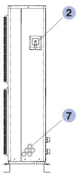
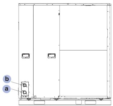
natural_image
Technical diagram of a rectangular enclosure or enclosure with labeled components (a and b), no readable text or symbols present.Component name
1 Electronic printed circuit board (view without top cabinet plate)
2 Safety valve (view without cover)
3 Flow rate cut-out
4 Monometer (water pressure gauge)
5 3-stage water circulation pump (Figure shows standard pump)
6 FI RCD breakers (differs from model to model, see Detail A)
7 Cable passage
8 Front plate
9 Top cabinet plate
10 Overload protection (differs from one model to the other, see Detail B)
11 Additional electric heater (3, 6 and/or 9 kW)
12 Expansion vessel
13 Cover
14 Deaeration
Connection name
a Return water pipe ∅ R 1¼
b Supply water pipe ∅ R 1¼
Components of the Monobloc unit with two fans
A
single phase, 6 and 9 kW
single phase, 12 to 16kW ONLY ON Phase-out models C & D series
three phase, 9kW
three phase, 12 to 16 kW
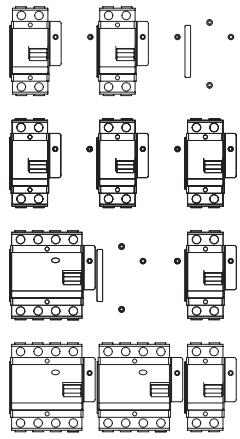
B
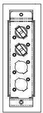
single phase,
6 and 9 kW
single phase,
12 to 16 kW
three phase,
9 to 16kW
Detail A (left) and B (right) of the components of the monobloc unit with two fans
Dimensional drawing for mini Monobloc unit with 5 to 9 kW nominal capacity
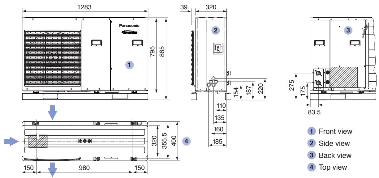
1 Front view
2 Side view
3 Back view
4 Top view
Dimensions of Monobloc unit with one fan in mm. The air flow is depicted by arrows.
Dimensional drawing for Monobloc unit with 9 to 16 kW nominal capacity
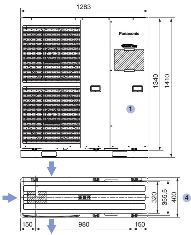

1 Front view
2 Side view
3 Back view
4 Top view
Dimensions of Monobloc unit with two fans in mm. The air flow is depicted by arrows.
| Monobloc system | Series | Aquarea LT | |||||||||||
| Phases | single phase | ||||||||||||
| Monobloc unit | Model | WH-MDC05F3E5* | WH-MDF06E3E5* | WH-MDF09E3E5* | WH-MDF09C3E5 | WH-MDF12C6E5 | WH-MDF12C6E5 | WH-MDF14C6E5 | WH-MDF14C6E5 | WH-MDF16C6E5 | WH-MDF16C6E5 | ||
| Output capacity | Heating capacity A-15/W35 | kW | 4.87 | 5.93 | 7.57 | 8.11 | 8.74 | 9.66 | 9.67 | ||||
| Power consumption A-15/W35 | kW | 1.98 | 2.53 | 3.6 | 3.29 | 3.78 | 4.23 | 4.38 | |||||
| Coefficient of performance A-15/W35 | - | 2.46 | 2.34 | 2.1 | 2.47 | 2.31 | 2.28 | 2.21 | |||||
| Heating capacity A-7/W35 | kW | 5.08 | 5.6 | 7.93 | 9.05 | 11.02 | 11.87 | 11.63 | |||||
| Power consumption A-7/W35 | kW | 1.50 | 1.99 | 3.49 | 3.17 | 3.9 | 4.34 | 4.37 | |||||
| Coefficient of performance A-7/W35 | - | 3.38 | 2.8 | 2.27 | 2.85 | 2.82 | 2.74 | 2.66 | |||||
| Heating capacity A2/W35 | kW | 4.75/3.31^2 | 5.23 | 7.51 | 8.85 | 11.88 | 12.66 | 12.83 | |||||
| Power consumption A2/W35 | kW | 1.23/0.81^2 | 1.48 | 2.38 | 2.47 | 3.45 | 3.90 | 3.96 | |||||
| Coefficient of performance A2/W35 | - | 3.88/4.07^2 | 3.54 | 3.15 | 3.58 | 3.44 | 3.25 | 3.24 | |||||
| Heating capacity A7/W35 | kW | 4.91 | 6.37 | 9.05 | 8.9 | 11.8 | 13.83 | 15.79 | |||||
| Power consumption A7/W35 | kW | 0.95 | 1.33 | 2.11 | 1.81 | 2.68 | 3.27 | 3.81 | |||||
| Coefficient of performance A7/W35 | - | 5.17 | 4.8 | 4.29 | 4.91 | 4.4 | 4.23 | 4.14 | |||||
| Heating capacity A2/W55 | kW | 3.40 | 5.0 | 7.0 | 8.8 | 9.1 | 9.5 | 9.8 | |||||
| Power consumption A2/W55 | kW | 1.64 | 2.5 | 3.88 | 3.98 | 4.18 | 4.4 | 4.55 | |||||
| Coefficient of performance A2/W55 | - | 2.07 | 2.0 | 1.8 | 2.21 | 2.18 | 2.16 | 2.15 | |||||
| Cooling capacity A35/W7 | kW | 4.50 | - | - | 6.97 | - | 10.0 | - | 11.5 | - | 11.93 | ||
| Power consumption A35/W7 | kW | 1.35 | - | - | 2.25 | - | 3.6 | - | 4.4 | - | 4.8 | ||
| Coefficient of performance (EER) A35/W7 | - | 3.33 | - | - | 3.15 | - | 2.78 | - | 2.61 | - | 2.51 | ||
| Acoustics | Sound pressure level ^1 | dB(A) | 47 | 47 | 49 | 49 | 50 | 51 | 53 | ||||
| Sound power level | dB(A) | A7/W35: 62^3 A7/W45: 62^3 A7/W55: 62^3 | 65 | 67 | 60 | 63 | 63 | 64 | |||||
| Fan speed, top (heating/cooling) | U/min | 580/700 | 580 | 640 | 490/540 | 510/600 | 540/630 | 580/630 | |||||
| Fan speed, bottom (heating/cooling) | U/min | 530/580 | 550/640 | 580/670 | 620/670 | ||||||||
| Air flow rate (heating/cooling) | m^3 /min | 43.3/47.1 | 46.7 | 51.6 | 76.8/89.5 | 80/93.3 | 84/97.8 | 90/97.8 | |||||
| Unit data | Dimensions (H×W×D) | mm | 865×1.283×320 | 1.410×1.283×320 | |||||||||
| Weight | kg | 107 | 112 | 153 | |||||||||
| Water-side connection | inch AG | R 1 1⁄4 | |||||||||||
| Pump - speed stepping | 7 | 3 | |||||||||||
| Pump - power consumption (max.) | W | 47 | 75 | 190 | |||||||||
| Volumetric flow rate of heating circuit for A7/W35/30 | I/min | 14.3 | 17.2 | 25.8 | 25.8 | 34.4 | 40.1 | 45.9 | |||||
| Minimum circulation | I/min | 10 | 19 | ||||||||||
| Safety valve (open/closed) | bar | 3/≤1.86 | 3/≤2.65 | ||||||||||
| Electric | Capacity of the additional electric heater | kW | 3 | 6 | |||||||||
| Power consumption (heating/cooling) | kW | 0.99/1.35 | 1.36 | 2.2 | 1.9/2.25 | 2.57/3.6 | 3.11/4.4 | 3.78/4.8 | |||||
| Operation and starting current (heating/cooling) | A | 6.1 | 6.2 | 10.1 | 8.7/10.2 | 11.6/16.1 | 14.1/19.7 | 17.1/21.5 | |||||
| Power supply 1 (current consumption) | A | 19.5 | 20.5 | 22.9 | 22.9 | 24 | 25 | 26 | |||||
| Power supply 1 (frequency/voltage) | Hz/V | 50/230 | |||||||||||
| Power supply 2 (current consumption) | A | 13 | 26 | ||||||||||
| Power supply 2 (frequency/voltage) | Hz/V | 50/230 | |||||||||||
| Power supply 3 (current consumption) | A | - | - | - | - | 13 | 13 | 13 | |||||
| Power supply 3 (frequency/voltage) | Hz/V | - | - | - | 50/230 | ||||||||
| Temp.-ranges | Operating range (outside temperature) | °C | -20 to 35 / 16 to 43 | ||||||||||
| Operating range (supply water temp. (H/C) | °C | 25 to 55 / 5 to 20 | |||||||||||
Technical data of the monobloc units
| Aquarea LT | Aquarea T-CAP | Aquarea HT | ||||||||||||||||||
| three phase | single phase | three phase | single phase | three phase | ||||||||||||||||
| WH-MDF09C3E8 | WH-MDC09C3E8 | WH-MDF12C9E8 | WH-MDC12C9E8 | WH-MDF14C9E8 | WH-MDC14C9E8 | WH-MDF16C9E8 | WH-MDF16C9E8 | WH-MXF09D3E5 | WH-MXC09D3E5 | WH-MXF12D6E5 | WH-MXC12D6E5 | WH-MXF09D3E8 | WH-MXC09D3E8 | WH-MXF12D9E8 | WH-MXC12D9E8 | WH-MHF09D3E5 | WH-MHF12D6E5 | WH-MHF09D3E8 | WH-MHF12D9E8 | |
| 7.99 | 8.93 | 9.77 | 10.14 | 9.23 | 12.06 | 9.0 | 12.0 | 9.0 | 12.0 | 9.0 | 12.0 | |||||||||
| 3.17 | 3.56 | 3.93 | 4.24 | 3.73 | 5.24 | 3.54 | 5.0 | 3.75 | 5.57 | 3.75 | 5.58 | |||||||||
| 2.52 | 2.51 | 2.48 | 2.39 | 2.5 | 2.32 | 2.54 | 2.4 | 2.4 | 2.15 | 2.4 | 2.15 | |||||||||
| 9.13 | 11.06 | 11.8 | 11.35 | 9.03 | 11.63 | 9.0 | 12.0 | 9.0 | 12.0 | 9.0 | 12.0 | |||||||||
| 3.04 | 3.65 | 4.04 | 4.11 | 3.15 | 4.51 | 3.2 | 4.44 | 3.33 | 4.8 | 3.33 | 4.8 | |||||||||
| 3.01 | 3.03 | 2.92 | 2.67 | 2.91 | 2.6 | 2.81 | 2.7 | 2.7 | 2.5 | 2.7 | 2.5 | |||||||||
| 9.01 | 11.92 | 12.68 | 12.65 | 9.22 | 11.76 | 9 | 12 | 9 | 12 | 9 | 12 | |||||||||
| 2.40 | 3.33 | 3.65 | 3.78 | 2.52 | 3.54 | 2.55 | 3.53 | 2.65 | 3.61 | 2.65 | 3.61 | |||||||||
| 3.75 | 3.58 | 3.47 | 3.35 | 3.66 | 3.32 | 3.53 | 3.4 | 3.4 | 3.32 | 3.4 | 3.32 | |||||||||
| 9.16 | 12.17 | 14.13 | 15.78 | 9.33 | 12.08 | 9 | 12 | 9.0 | 12.0 | 9.0 | 12 | |||||||||
| 1.82 | 2.6 | 3.15 | 3.73 | 1.96 | 2.6 | 1.9 | 2.57 | 1.98 | 2.73 | 1.98 | 2.73 | |||||||||
| 5.03 | 4.68 | 4.49 | 4.23 | 4.89 | 4.73 | 4.74 | 4.67 | 4.55 | 4.4 | 4.55 | 4.4 | |||||||||
| 8.8 | 9.1 | 9.5 | 9.8 | 9.0 | 12.0 | 9.0 | 12.0 | 9.0 | 10.8 | 9.0 | 10.8 | |||||||||
| 3.98 | 4.18 | 4.4 | 4.55 | 4.11 | 5.51 | 4.11 | 5.51 | 3.92 | 4.9 | 3.91 | 4.91 | |||||||||
| 2.21 | 2.18 | 2.16 | 2.15 | 2.19 | 2.18 | 2.19 | 2.18 | 2.3 | 2.2 | 2.3 | 2.2 | |||||||||
| - | 7.2 | - | 10.0 | - | 11.5 | - | 12.4 | - | 7.0 | - | 10.0 | - | 7.0 | - | 10.0 | - | - | - | ||
| - | 2.25 | - | 3.6 | - | 4.4 | - | 4.8 | - | 2.25 | - | 3.6 | - | 2.25 | - | 3.6 | - | - | - | ||
| - | 3.33 | - | 2.78 | - | 2.61 | - | 2.67 | - | 3.11 | - | 2.78 | - | 3.11 | - | 2.78 | - | - | - | ||
| 49 | 50 | 51 | 53 | 49 | 50 | 49 | 50 | 49 | 50 | 49 | 50 | |||||||||
| 60 | 62 | 64 | 65 | 60 | 60 | 66 | 67 | 66 | 67 | 66 | 67 | |||||||||
| 490/540 | 510/600 | 540/630 | 580/630 | 490/540 | 510/600 | 490/540 | 510/600 | 490 | 520 | 490 | 520 | |||||||||
| 530/580 | 550/640 | 580/670 | 620/670 | 530/580 | 550/640 | 530/580 | 550/640 | 530 | 560 | 530 | 560 | |||||||||
| 76.8/89.5 | 80/93.3 | 84/97.8 | 90/97.8 | 76.8/89.5 | 80/93.3 | 76.8/89.5 | 80/93.3 | 76.8 | 80 | 76.8 | 80 | |||||||||
| 1.410 × 1.283 × 320 | ||||||||||||||||||||
| 157 | 155 | 158 | n.v. | n.v. | ||||||||||||||||
| R 114 | ||||||||||||||||||||
| 3 | ||||||||||||||||||||
| 190 | ||||||||||||||||||||
| 25.8 | 34.4 | 40.1 | 45.9 | 25.8 | 34.4 | 25.8 | 34.4 | 25.8 | 34.4 | 25.8 | 34.4 | |||||||||
| 10 | 19 | 10 | 19 | 10 | 19 | 10 | 19 | 10 | 19 | |||||||||||
| 1.9/≤ 1.83 | 3.0/≤ 2.65 | |||||||||||||||||||
| 3 | 9 | 3 | 6 | 3 | 9 | 3 | 6 | 3 | 6 | |||||||||||
| 1.9/2.25 | 2.57/3.6 | 3.11/4.4 | 3.78/4.8 | 1.9 | 2.57 | 1.9 | 2.57 | 1.98 | 2.73 | 1.98 | 2.73 | |||||||||
| 2.9/3.4 | 3.9/5.3 | 4.7/6.6 | 5.7/7.2 | 8.8 | 10.4 | 11.9 | 16.7 | 2.9 | 3.9 | 9.5 | 13 | 9.5 | 12.8 | |||||||
| 11.8 | 8.8 | 9.4 | 9.9 | 25 | 29 | 14.7 | 11.9 | 28.5 | 29 | 32.8 | 29 | |||||||||
| 50/400 | 50/230 | 50/400 | 50/230 | 50/400 | ||||||||||||||||
| 13 | 26 | 13 | 26 | 13 | ||||||||||||||||
| 50/230 | 50/230 | 50/230 | 50/230 | 50/230 | ||||||||||||||||
| - | 13 | 13 | 13 | - | 13 | - | 13 | - | 13 | - | 13 | |||||||||
| - | 50/400 | - | 50/230 | - | 50/400 | - | 50/230 | - | 50/400 | |||||||||||
| -20 to 35 | -20 to 35 | -20 to 35 | ||||||||||||||||||
| 22 to 55 / 5 to 20 | 25 to 65 | 25 to 65 | ||||||||||||||||||
3.3 Accessories
3.3.1 Hot water tank
The hot water tank is used for the storage of domestic hot water before use. In addition to the tank being heated from the Aquarea heat pump, it is also possible to utilise solar heat from a connected solar thermal installation. Furthermore, an electric immersion heater with a capacity of 3 kW ensures hot water supply at very low outside temperatures and can also be used for Legionella control.
Panasonic offers a total of three different tank models in different sizes (180 to 400 L) for easy water heating for different requirements:
For easy installation and integration of all Aquarea tank models into the heat pump system, the following components are supplied with the Aquarea tank:
• Three port motorised valve
- Tank temperature sensor (6 m cable)
• Cold water inlet PRV combination valve/expansion relief
• Pressure and temperature relief valve
• Control thermostat
• Energy cut-out thermostat
• Energy cut-out motorised valve (indirects only)
- Tundish
• 3 kW Immersion heater including control and cut out thermostats
- Expansion vessel/mounting bracket/flexible hose
• Technical/user product literature
Aquarea is a range of unvented hot water storage cylinders, manufactured in the latest high quality duplex stainless steel. They are designed to provide mains pressure hot water and are supplied as a package which complies with Section G3 of the Building Regulations. The appliance is extremely well insulated using high density HCFC free foam insulation with an ozone depleting potential (ODP) of zero and a global warming potential (GWP) of 1.
It is fitted with all necessary safety devices and supplied with all the necessary control devices to make installation on site as easy as possible.
Aquarea Heat Pump (HP) cylinders
The Aquarea HP cylinder is an unvented hot water storage cylinder fitted with two high efficiency internal primary heat exchangers especially designed for use with heat pump systems. These two heat exchangers must be connected in parallel to the heat pump circuit when a solar thermal system is not installed, as shown below. When both heat pump and solar thermal systems are installed, the top heat exchanger is connected to the heat pump circuit and the bottom heat exchanger is connected to the solar circuit as shown below.
All Aquarea HP cylinders are fitted with 3 kW (230 Vac, 50 Hz) immersion heater for raising the temperature of the stored water to above 50/60 °C after the heat pump heating cycle (if necessary). The Aquarea HP remote controller will boost when required and control sterilisation on a weekly basis. Please refer to the heat pump manual for further details.
Important notes
- All Aquarea HP cylinders are suitable for both open vented and sealed primary systems. Minimum 5 m H_2O working pressure.
- When used with a sealed primary heating system, the heat pump must incorporate its own over heat thermostat.
- Aquarea HP cylinders must not be used with solid fuel boilers or steam as the heat source.
- Heat pumps can normally only heat the domestic hot water to between 45–50/60°C. The Aquarea heat pump remote controller will operate a cylinder sterilisation on a weekly basis. See heat pump manual for further details.
- The cold supply elbow c/w drain tapping must be fitted. A flexible hose can then be connected to the drain tapping and providing the hose runs below the lowest level of the cylinder, then all the water content can be drained out by the symphonic action.
Aquarea Heat Pump (HP) Slimline models
The Aquarea HP Slimline cylinder is an unvented hot water storage cylinder fitted with a 3 m^2 high efficiency coil. The coil has a low pressure loss due to it being a multiple pass coil which enable high flow rates to be achieved through it. In addition due to the coil being corrugated the heat transfer rate is higher than that of plain tube coil.
The cylinder has been specifically designed for heat pump applications. It incorporates an immersion heater at the base of the unit which enables pasteurisation of the water.
This should be done on a regular basis in line with HWA guidance. The Aquarea heat pump controller handles this operation.
It has been designed on a slimline basis to enable it to fit into tighter locations.
| Aquarea HP cylinder | ASLPAN180HP | ASLPAN300HP | ASLPAN400HP | ||
| Capacity – total volume | litres | 180 | 300 | 400 | |
| Volume heated by IH | litres | 113 | 195 | 270 | |
| Dedicated solar volume | litres | 65 | 105 | 130 | |
| Standing heat loss rate | kWh/24h | 1.48 | 2.04 | 2.82 | |
| Weight – empty/full | kg | 33/213 | 49/349 | 61/461 | |
| Pressure regulating valve setting | bar | 3 | 3 | 3 | |
| Expansion relief valve setting | bar | 4.75 | 4.75 | 4.75 | |
| Temperature setting (P&T valve) | °C | 95 | 95 | 95 | |
| Pressure setting (P&T valve) | bar | 6.0 | 6.0 | 6.0 | |
| Expansion vessel size (volume) | litres | 18 | 35 | 2×24 | |
| Expansion vessel initial charge pressure | bar | 3 | 3 | 3 | |
| Height | A | mm | 1,305 | 1,992 | 2,030 |
| Diameter | B | mm | 550 | 550 | 630 |
| 22 mm secondary return | C | mm | - | 1,577 | 1,592 |
| 22 mm compression cold feed | D | mm | 442 | 522 | 557 |
| P&T valve | E | mm | 1,053 | 1,720 | 1,784 |
| 22 mm solar return – bottom coil | F | mm | 223 | 223 | 238 |
| 22 mm solar flow – bottom coil | G | mm | 352 | 472 | 548 |
| 28 mm primary return – top coil | H | mm | 467 | 742 | 641 |
| 28 mm primary flow – top coil | I | mm | 1,072 | 1,562 | 1,791 |
| Dual CT & OHT pocket – 1 top | J | mm | 732 | 1,092 | 1,076 |
| Dual CT & OHT pocket – 2 bottom | K | mm | 419 | 539 | 651 |
| Solar sensor pocket – 1 top | L | mm | 882 | 1,367 | 1,382 |
| Solar sensor pocket – 2 bottom | M | mm | 203 | 262 | 334 |
| 3 kW immersion heater height | N | mm | 457 | 702 | 640 |
| Surface area of solar heater coil | m^2 | 0.68 | 0.97 | 1.27 | |
| Solar coil pressure loss^1 | bar | 0.191 | 0.241 | 0.31 | |
| Primary heat exchanger surface area | m^2 | 1.36 | 2.04 | 2.91 | |
| Primary heat exchanger thermal rating^1 | kW | 24.3 | 34.2 | 47.2 | |
| Primary heat exchanger pressure loss^1 | bar | 0.048 | 0.019 | 0.027 | |
| Heat up time from 15 °C to 60 °C ^2 | min | 33 | 48 | 49 | |
| Recovery time after 70% draw-off ^2 | min | 21 | 32 | 38 | |
| ^1Measured at 0.25l/s primary flow rate | ^2Measured at 0.25l/s primary flow rate and at 82°C flow temperature | ||||
Table 1
Note
Not all models – see table 1.
Recovery times based on Primary Coil/I.H. duty (ie. assumes the boiler output is adequate).
All connections are supplied with compression fittings for direct connection to copper pipework.
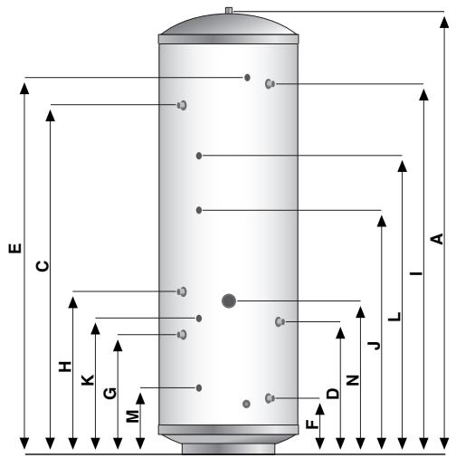
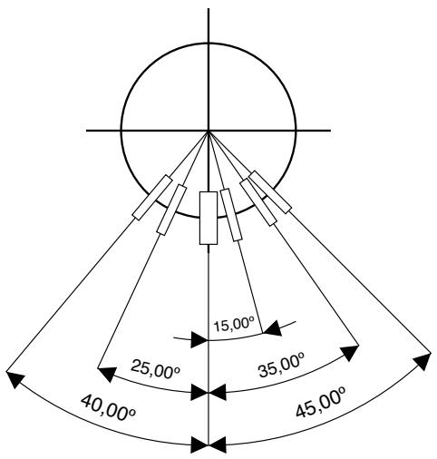
| Aquarea Slimline HP cylinder | ASLPAN180HPSL | ||
| Capacity – total volume | litres | 180 | |
| Volume heated by IH | litres | 170 | |
| Dedicated solar volume | litres | - | |
| Standing heat loss rate | kWh/24h | 2.01 | |
| Weight – empty/full | kg | 33/213 | |
| Pressure regulating valve setting | bar | 3 | |
| Expansion relief valve setting | bar | 4.75 | |
| Temperature setting (P&T valve) | °C | 95 | |
| Pressure setting (P&T valve) | bar | 6.0 | |
| Expansion vessel size (volume) | litres | 18 | |
| Expansion vessel initial charge pressure | bar | 3 | |
| Height | A | mm | 1,790 |
| Diameter | B | mm | 475 |
| 22 mm secondary return | C | mm | - |
| 22 mm compression cold feed | D | mm | 283 |
| P&T valve | E | mm | 1,535 |
| 22 mm solar return | F | mm | - |
| 22 mm solar flow | G | mm | - |
| 28 mm primary return | H | mm | 275 |
| 28 mm primary flow | I | mm | 1,545 |
| HP control thermostat | J | mm | 628 |
| Dual CT & OHT pocket | K | mm | 628 |
| Solar sensor pocket – 1 top | L | mm | - |
| Solar sensor pocket – 2 bottom | M | mm | - |
| 3 kW immersion heater height | N | mm | 207 |
| Surface area of solar heater coil | m^2 | - | |
| Solar coil pressure loss^1 | bar | - | |
| Primary heat exchanger surface area | m^2 | 3.01 | |
| Primary heat exchanger thermal rating ^1 | kW | 32.8 | |
| Primary heat exchanger pressure loss^1 | bar | 0.018 | |
| Heat up time from 15°C to 60°C ^2 | min | 33 | |
| Recovery time after 70% draw-off ^2 | min | 21 | |
| ^1 Measured at 0.25 l/s primary flow rate ^2 Measured at 0.25 l/s primary flow rate and at 82°C flow temperature | |||
Table 2
Note
Not all models – see table 2.
Recovery times based on Primary Coil/I.H. duty (ie. assumes the boiler output is adequate).
All connections are supplied with compression fittings for direct connection to copper pipework.
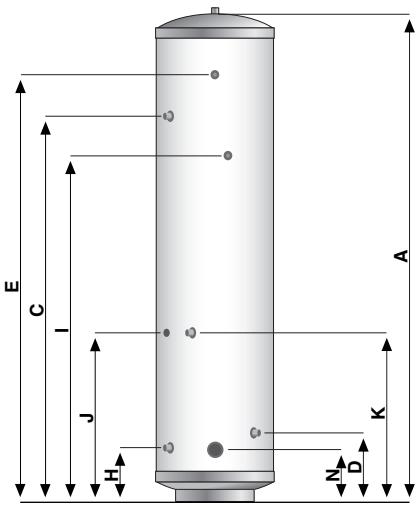
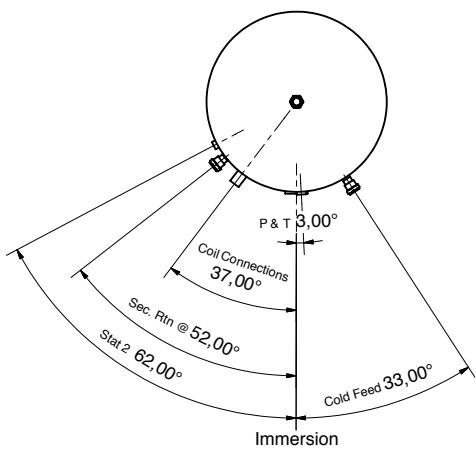
Aquarea HP cylinder
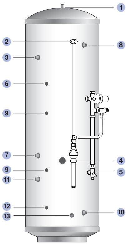
Typical arrangement of component kit shown fitted to the appliance for clarity. Pipework to be supplied and fitted by installer.
Basic Appliance
1 Hot water draw off (22 mm) compression
2 Temperature & pressure relief valve 92–95°/6 bar
3 Hot water secondary return 22 mm (not fitted to smaller sizes, see table 1)
4 Immersion heater 1 ^3/4 " BSP 3kW
5 22 mm cold supply
6 Thermostat pocket (22 mm)
7 Primary return (28 mm)
8 Primary flow (28 mm)
9 Dual control/Overheat stat & solar thermostat pocket
10 Solar coil return to panel collector (22 mm) compression
11 Solar coil flow from panel (22 mm) compression
12 Solar thermostat pocket
13 Drain off
Part G3 loose components supplied in a separate box
A Combination inlet group incorporating pressure reducing valve, strainer, check valve, balance cold take off point, expansion relief valve and expansion vessel connection points.
B Potable expansion vessels c/w flexible hose and wall bracket
C Tundish
D Dual control thermostat and combined overheat thermostat ( × 2)
E Three port motorised valve for primary circuit
F Wiring junction box for primary system
Aquarea HP Slimline
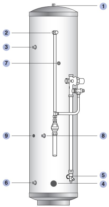
Typical arrangement of component kit shown fitted to the appliance for clarity. Pipework to be supplied and fitted by installer.
Basic Appliance
1 Hot water draw off (22 mm) compression
2 Temperature & pressure relief valve 92–95°/6 bar
3 Hot water secondary return 22 mm (210 litre model only)
4 Immersion heater 1 ^3/4 " BSP 3kW
5 22mm cold supply
6 Primary return (28 mm)
7 Primary flow (28 mm)
8 Dual control/Overheat stat
9 HP control thermostat
Part G3 loose components supplied in a separate box
A Combination inlet group incorporating pressure reducing valve, strainer, check valve, balance cold take off point, expansion relief valve and expansion vessel connection points.
B Potable expansion vessels c/w flexible hose and wall bracket
C Tundish
D Dual control thermostat and combined overheat thermostat ( × 2)
E Three port motorised valve for primary circuit
F Wiring junction box for primary system
Configuration without solar fitted
Schematic Open Vented Primary System
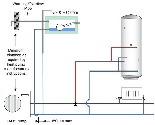
Schematic Open Vented Primary System (Slimline models)
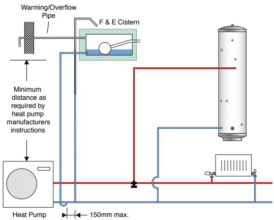
Schematic Sealed Primary System
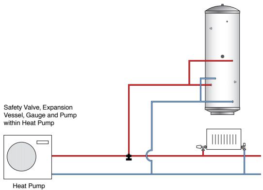
Schematic Sealed Primary System (Slimline models)
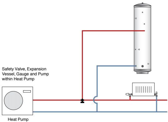
Aquarea HP cylinder without solar heating system
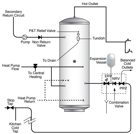
flowchart
graph TD
    A["Stop Tap"] --> B["Heat Pump Return"]
    C["Kitchen Cold Tap"] --> B
    B --> D["To Central Heating"]
    D --> E["Pump"]
    E --> F["P&T Relief Valve"]
    F --> G["Tundish"]
    G --> H["Hot Outlet"]
    H --> I["Expansion Vessel"]
    I --> J["ERV"]
    I --> K["NRV"]
    I --> L["PRV"]
    L --> M["Combination Valve"]
    M --> N["Balanced Cold Outlets"]
    N --> O["Secondary Return Circuit"]
    style A fill:#f9f,stroke:#333
    style C fill:#f9f,stroke:#333
    style D fill:#ccf,stroke:#333
    style E fill:#cff,stroke:#333
    style F fill:#ffc,stroke:#333
    style G fill:#cfc,stroke:#333
    style H fill:#fcc,stroke:#333
    style I fill:#fcf,stroke:#333
    style J fill:#cff,stroke:#333
    style K fill:#cff,stroke:#333
    style L fill:#cff,stroke:#333
    style M fill:#ffc,stroke:#333
    style N fill:#ffc,stroke:#333
    style O fill:#ffc,stroke:#333
Aquarea Slimline HP cylinder without solar heating system
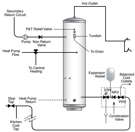
flowchart
graph TD
    A["Secondary Return Circuit"] --> B["Pump"]
    B --> C["Non Return Valve"]
    C --> D["Tundish"]
    D --> E["To Drain"]
    E --> F["Expansion Vessel"]
    F --> G["RRV"]
    G --> H["NRV"]
    H --> I["PRV"]
    I --> J["Combination Valve"]
    J --> K["Stop Tap"]
    K --> L["Heat Pump Return"]
    L --> M["Kitchen Cold Tap"]
    M --> N["Stop Tap"]
    N --> O["Heat Pump Flow"]
    O --> P["To Central Heating"]
    P --> Q["P&T Relief Valve"]
    Q --> R["Pump"]
Aquarea HP system configuration with solar thermal heating system
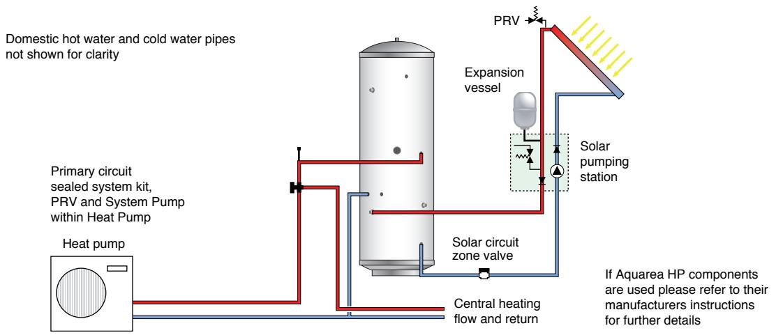
flowchart
graph TD
    A["Domestic hot water and cold water pipes not shown for clarity"] --> B["Heat pump"]
    B --> C["Primary circuit sealed system kit, PRV and System Pump within Heat Pump"]
    C --> D["Expansion vessel"]
    D --> E["Solar pumping station"]
    E --> F["Central heating flow and return"]
    F --> G["Solar circuit zone valve"]
    G --> H["PRV"]
    H --> I["Output"]
Aquarea HP cylinder with solar heating system
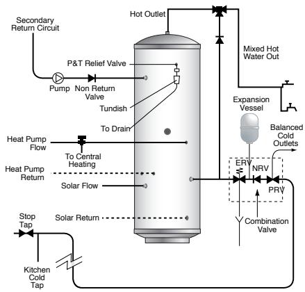
flowchart
graph TD
    A["Secondary Return Circuit"] --> B["Pump"]
    B --> C["Non Return Valve"]
    C --> D["Tundish"]
    D --> E["To Drain"]
    E --> F["Heat Pump Flow"]
    F --> G["To Central Heating"]
    G --> H["Heat Pump Return"]
    H --> I["Solar Flow"]
    I --> J["Solar Return"]
    J --> K["Stop Tap"]
    K --> L["Kitchen Cold Tap"]
    M["Hot Outlet"] --> N["Mixed Hot Water Out"]
    O["Expansion Vessel"] --> P["ERV"]
    P --> Q["NRV"]
    Q --> R["PRV"]
    R --> S["Combination Valve"]
    T["Balanced Cold Outlets"] --> U["ERV"]
    U --> V["NRV"]
    V --> W["PRV"]
General Design Considerations
The cupboard footprint needs to be at least 650mm square for units up to 300 litres, 730mm for 400 litre units.
The base chosen for the cylinder should be level and capable of supporting the weight of the unit when full of water as shown in General Data. The discharge pipework for the safety valves must have a minimum fall of 1:200 from the unit to a safe discharge point.
All exposed pipework and fittings on the cylinder should be insulated, and the unit should NOT be fixed in a location where the contents could freeze.
In replacement systems, whenever a boiler or hot water storage vessel is replaced in an existing system, any pipes that are exposed as part of the work or are otherwise accessible should be insulated as recommended for new systems, or to some lesser standard where practical constraints dictate.
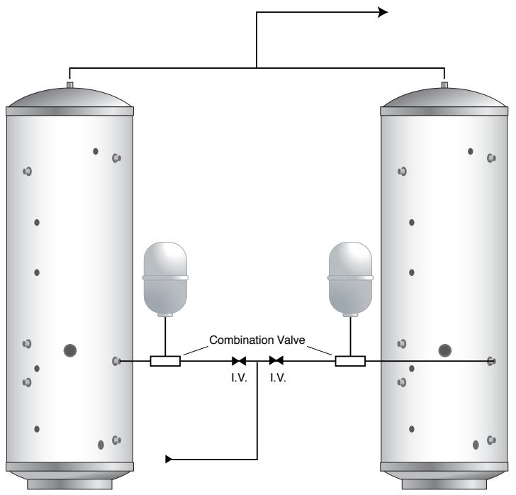
flowchart
graph TD
    A["Top Tank"] --> B["Bottom Tank"]
    B --> C{Combination Valve}
    C -->|I.V.| D["Bottom Tank"]
    C -->|I.V.| E["Top Tank"]
    style A fill:#f9f,stroke:#333
    style B fill:#bbf,stroke:#333
    style C fill:#dfd,stroke:#333
    style D fill:#dfd,stroke:#333
    style E fill:#dfd,stroke:#333
If two Aquareas are coupled together the secondary inlet and outlet pipes must be balanced. The units must be fitted on the same level.

Note
No valves must be fitted between the expansion vessel and the storage cylinder(s).
3.3.2 Extras
Panasonic offers special accessories for easy combination of Aquarea heat pumps with tanks or solar thermal systems already existing in the building. Likewise an auxiliary heater unit is available, which prevents the formation of ice on the outdoor units, which blocks air movement.
| Group | Designation | Description | Function |
| Solar | CZ-NS1P | Add-on circuit board for solar connection (bi-bloc systems) | Circuit board provides communication between the solar station (on-site customer unit) and the Aquarea controller |
| CZ-NS2P | Add-on circuit board for solar connection (monobloc systems) | ||
| CZ-NS3P | Add-on circuit board for solar connection (mini monobloc systems) | ||
| Hot-water tank | CZ-TK1 | Temperature sensor installation set for third party tanks | Tank sensor with 6 m cable and immersion sleeve for installation in third party tanks |
| PAW-TS1 | Tank sensor with 6 m cable | ||
| PAW-TS2 | Tank sensor with 20 m cable | ||
| Housing heating | CZ-NE1P | Base pan heater for the Aquarea T-CAP and Aquarea HT series and mini monobloc units in the Aquarea LT series (not for 3 kW and 5 kW units) | Heating tape fitted in the unit housing (outdoor unit) on the base plate to prevent the water formed on defrosting from freezing |
| CZ-NE2P | Base pan heater for 3 kW and 5 kW units | ||
| CZ-NE3P | Base pan heater for all F generation units: F3, F6 and F9 |

Note
The additional PCB for the solar thermal connection does not replace the solar controller, but rather serves as a means of communication and optimisation. To combine Aquarea heat pumps with a solar thermal installation, a separate solar controller (to be provided by the customer) is required in addition to the additional PCB.
This option is required for single coil heat pump cylinders without the option of a solar coil inside the cylinder.
4 Closed-loop control
4.1 Design
The operation and programming of the Aquarea heat pump takes place in a simple manner by means of the controller on the hydromodule (Bi-Bloc system) and/or by means of the wired remote control (Monobloc system) within the building. The controller (Bi-Bloc) and wired remote controller (Monobloc) are similar in design and are provided with an LCD-display for the indication of essential operating parameters. Clearly arranged keys are used for the operation of these controllers.
4.2 Functions
All basic functions for the operation of the Aquarea heat pump are included in the controller. Furthermore, the controller is provided with other functions that can be activated upon demand. For the combination of the Aquarea heat pump with external devices, e.g. a solar thermal installation or a room thermostat, the controller offers the required interfaces which if necessary can be used in combination with other accessories.
4.2.1 Basic functions
- Automatic control of supply water temperature for the operating modes heating, heating + water heating, water heating, cooling + water heating or cooling depending on the outside temperature, the preset values and the current operating conditions.
- At the same time, the valves are switched from heating and/or cooling to water heating and thus deactivating the heating circuits in cooling mode.
- Electric immersion heater and additional electric heater – when activated – are automatically switched on e.g. for quick heat-up of the hot water tank or for supporting the heat pump during extremely low outside temperatures.
1 OFF/ON-LED ①
Illuminates during operation and flashes upon occurrence of an error
2 REMOTE display
Symbol is displayed when an external room thermostat is connected and activated
3 SOLAR display
Symbol is displayed when an external solar thermal installation is connected and activated
4 FORCE display
Symbol is displayed when the FORCE mode is activated (additional electric heater can heat)
5 HEATER display
Symbol is displayed when the additional electric heater is activated (additional electric heater can heat)
6 TANK display
Symbol will be shown during the hot water mode (Aquarea heat pump heating the tank)
7 COOL display
Symbol will be shown during the cooling mode (Aquarea heat pump cooling)
8 HEAT display
Symbol will be shown during the heating mode (Aquarea heat pump heating)
9 AUTO display
Symbol is shown during automatic operation
10 TIMER display
Shows the setting of the 24-hour timer for each weekday with clock
11 OUTDOOR display
Shows the current outside temperature
12 WATER OUTLET display
Shows the current output water temperature of the Aquarea heat pump
13 HEATER display
Symbol is displayed when the additional electric heater is in operation
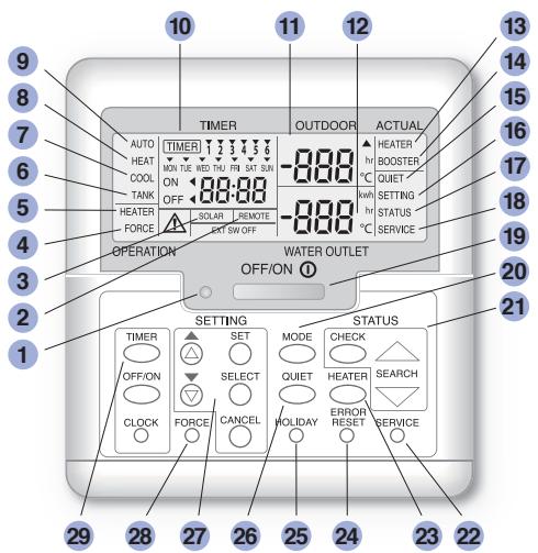
14 BOOSTER display
Symbol is displayed when the electric immersion heater in the hot water tank is in operation
15 QUIET display
Symbol will be shown when the quiet mode is activated
16 SETTING display
Symbol will be displayed when parameters in the settings are set
17 STATUS display
Symbol will be displayed when values are depicted in the status menu
18 SERVICE display
Symbol is displayed in service mode
19 OFF/ON key ①
Starts or stops the operation of the unit
20 MODE key
Serves for setting the operation mode: Heating, Heating + Hot water, Hot water, Cooling + Hot water or Cooling
21 STATUS keys
For checking the system status (compressor frequency, fault history, return water temperature, tank temperature)
22 SERVICE key
For the activation of the circulation pump and the pump down operation
23 HEATER key
For activating the additional electric heater
24 ERROR RESET key
For the reset of the remote controller or wired remote control and for acknowledging the error code
25 HOLIDAY key
For setting the holiday mode with energy-saving operation for a configurable number of days
26 QUIET key
For the activation of quiet mode with reduced noise production
27 SETTING key
For setting the heating curve, the heating limit temperature, the cooling temperature as well as the hot water temperature and functions
28 FORCE key
For activating the heat pump electric submersible heater (emergency operation)
29 TIMER keys
For setting the system time
Display and operating keys for easy operation and programming of the Aquarea control via the controller or wired remote control (Bi-Bloc or monobloc system)

Note
The illustrated control panel applies to units of the new F generation. Units of the older generations up to the E generation have a different control panel (see next page).
As the same operator control panel is used for different devices, some functions may not apply for your device.
1 OFF/ON-LED ①
Illuminates during operation and flashes upon occurrence of an error
2 REMOTE display
Symbol is displayed when an external room thermostat is connected and activated
3 SOLAR display
Symbol is displayed when an external solar thermal installation is connected and activated
4 FORCE display
Symbol is displayed when the FORCE mode is activated (additional electric heater can heat)
5 HEATER display
Symbol is displayed when the additional electric heater is activated (additional electric heater can heat)
6 QUIET display
Symbol will be shown during the hot water mode (Aquarea heat pump heating the tank)
8 COOL display
Symbol will be shown during the cooling mode (Aquarea heat pump cooling)
9 HEAT display
Symbol will be shown during the heating mode (Aquarea heat pump heating)
10 TIMER display
Shows the setting of the 24-hour timer for each weekday with clock
11 OUTDOOR display
Shows the current outside temperature
12 WATER OUTLET display
Shows the current output water temperature of the Aquarea heat pump
13 HEATER display
Symbol is displayed when the additional electric heater is in operation
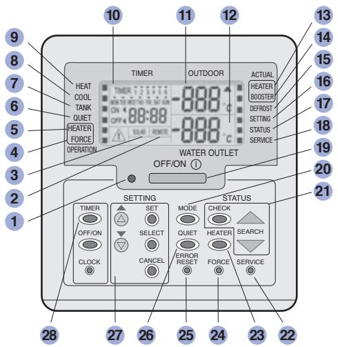
14 BOOSTER display
Symbol is displayed when the electric immersion heater in the hot water tank is in operation
15 DEFROST display
Symbol is displayed when defrosting
16 SETTING display
Symbol will be displayed when parameters in the settings are set
17 STATUS display
Symbol will be displayed when values are depicted in the status menu
18 SERVICE display
Symbol is displayed in service mode
19 OFF/ON key ①
Starts or stops the operation of the unit
20 MODE key
Serves for setting the operation mode: Heating, Heating + Hot water, Hot water, Cooling + Hot water or Cooling
21 STATUS keys
For checking the system status (compressor frequency, fault history, return water temperature, tank temperature)
22 SERVICE key
For the activation of the circulation pump and the pump down operation
23 HEATER key
For activating the additional electric heater
24 FORCE key
For the activation of additional electric heater (emergency operation)
25 ERROR RESET key
For the reset of the remote controller or wired remote control and for acknowledging the error code
26 QUIET key
For the activation of quiet mode with reduced noise production
27 SETTING key
For setting the heating curve, the heating limit temperature, the cooling temperature as well as the hot water temperature and functions
28 TIMER keys
For setting the system time
Display and operating keys for easy operation and programming of the Aquarea control via the remote controller or wired remote control (Bi-Bloc system or monobloc system)

Note
The illustrated control panel applies to devices up to the E generation. Devices of the newer F generation have a different control panel (see previous page). As the same operator control panel is used for different devices, some functions may not apply for your device.
4.2.2 Further functions
- Pump control: Monitoring of the operating condition upon switching on the heat pump – only when all the required criteria are positively checked does the heat pump transform into the normal mode. Should one criteria not correspond to the expected value, the heat pump goes into the error state.
- Service mode: Is used for the activation of the circulation pump and the pump down operation.
- Flow rate cut-out: Monitors the water flow rate and switches the heat pump off, when the minimum flow rate is not attained.
- Additional electric heater mode: The additional electric heater can be operated as backup when the heat pump malfunctions. For this purpose, the additional electric heater must be switched on manually.
• Monitoring the maximum return water temperature:
The return water temperature is checked during the start of operation, should this temperature exceed 80^ C, the pump will be switched off. - Defrosting function: By taking into account the outdoor temperature and supply water temperature as well as their fluctuations, this function ensures that ice that forms on the air-to-water heat exchanger of the outdoor unit or Monobloc unit is defrosted.
- Automatic restart: For controlled start after abrupt interruption of the power supply.
- Sterilisation mode: Weekly thermal sterilization of the hot water tank by means of the electric immersion heater. Adjustable using the 24-hour timer.
- Whisper-quiet operation: Reduces the compressor operating frequency as well as the fan speed of the outdoor or Monobloc unit by 80 rpm to at least 200 rpm, thus reducing the noise level.
- Solar mode: Expands the system by integrating an external solar thermal control system into the heat pump controller. For the solar operation, a tank as well as the additional PCB for solar thermal connection must be available. The solar thermal installation itself is controlled by an external solar thermal controller (to be provided by the customer).
- Operation with an external room thermostat: Without an external room thermostat, the Aquarea heat pump works via an internal thermostat function that monitors supply water and return water temperature and compares it with the heating curve. Upon exceeding the nominal supply water temperature by 2K the compressor switches off. The operation with external room thermostat can prevent frequent switch on-and-off, in that the room temperature is additionally considered for control of the heat pump.
- Additional housing heating (optional): Can be activated in the "Base Pan Heater" (applies to F generation units or later)
- Screed-drying function: (applies to F generation units or later)
4.2.3 Safety functions
Besides the listed functions, the control system also contains a series of further internal functions that ensure minimum compressor operation time, total current limitation, overheating protection for the compressor and protection functions for extreme operating conditions as well as other safety features.
4.3 Extensions and external interfaces
4.3.1 External room thermostat
Operation with external room thermostat can prevent frequent switch on-and-off, in that the room temperature is additionally considered for control of the heat pump. For this purpose, a room thermostat with two-step controller is needed. Depending on the current room temperature and adjustable required temperature, either the circuit L/L1 or the circuit L/L2 will be switched on via a potential-free switch-over contact.
Depending on which operating mode of the Aquarea heat pump is activated (Heating or Cooling), the heat pump will be activated or deactivated via the two-step controller. The operating mode of the heat pump (Heating or Cooling) acts like an internal release. For example, if the heat pump is in the heating mode, then closing the circuit L/L2 deactivates the heat pump. Only when an internal release exists by switching over into the Cooling mode, closing the circuit L/L2 actually leads to activation of the cooling mode.
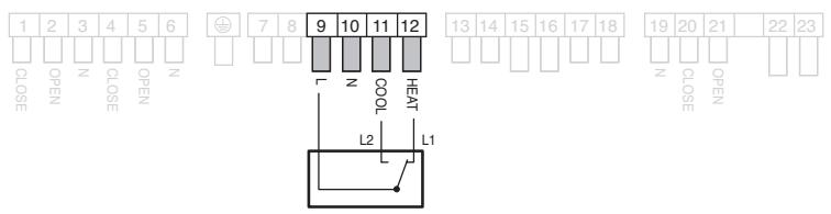
| Condition | L/L1 | L/L2 |
| Required temperature < room temperature | Circuit is open (Heating off) | Circuit is closed (Cooling on) |
| Required temperature > room temperature | Circuit is closed (Heating on) | Circuit is open (Cooling off) |
| Operating mode - heat pump | Heating | Cooling |
Connection diagram for the control of Aquarea heat pump via an external room thermostat. The room thermostat is connected to the terminals 9 to 12 of the terminal strip.

Note
For exclusive control of the heating mode via the external room thermostat, only the phases L and L1 are connected to the terminal strip. This also effects the Aquarea heat pump series without the cooling mode.
4.3.2 Deactivation of heating circuits in cooling mode
Heating circuits that can be used exclusively for the heating mode and not for the cooling mode (e.g. radiators), can be deactivated automatically by means of an external 2-way directional valve on the control system of the Aquarea heat pump in the cooling mode (see e.g. Hydraulic Diagrams 3 and 6).
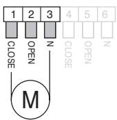
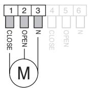
Connection diagram for the automatic deactivation of heating circuits in cooling mode via 2-way directional valves to the connections 1 to 3 of the terminal strip.
Left: Spring loaded 2-way directional valve, open without current, right: Motor-driven 2-way directional valve with single-pole change-over switch.
4.3.3 External control of the Aquarea heat pump
To be able to control the Aquarea heat pump by means of an external controller, the latter can be activated and deactivated by means of its own interface. The interface consists of a 2-position contact, which in the closed state activates the heat pump. An external, overriding control system can control several heat generators in paralell or in cascade sequence via the interface (see e.g. Hydraulics 9 and 10).
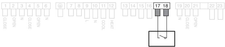
Connection of the external control to the terminals 17 and 18 of the terminal strip

Note
In the delivery state, the terminals 17 and 18 are bridged.
The Aquarea heat pump is thereby activated.
4.3.4 External solar thermal installation
This interface serves for the combination of Aquarea heat pump with a solar thermal installation for water heating via the Panasonic hot water tank. Operation of the heat pump is adapted based on an additional PCB that is available as an accessory for solar thermal connection for operation of the solar thermal installation. In addition, via an inherent input one can check whether the solar pump is running or not. As soon as a 230 V (AC) voltage is available at the respective input (solar pump running), the externally connected 3-way directional valve will be opened via the control system of the Aquarea heat pump, so that heat from the solar circuit can be output directly to the hot water tank. When the external solar controller switches on the solar pump, the external 3-way directional valve will be connected again (see also Hydraulic Diagram 4) via the control system of the Aquarea heat pump.
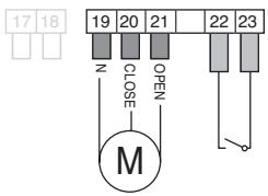
Connection of the external 3-way directional valve and the input signal of the solar pump to the terminals 19 to 21 or 22 and 23 of the terminal strip. The 3-way directional valve has to be connected such that in that it prevents the passage from solar circuit and heat exchanger of the hot water tank.

Note
For the combination of the Aquarea heat pump with a solar thermal installation, a solar pump must be used with a heat exchanger. Through this, the solar heat is first transferred from the solar circuit to the heating system water and subsequently to the hot water in the hot water tank.
The additional PCB for the solar connection does not replace the solar controller, but rather serves as a means of communication and optimisation. To combine Aquarea heat pumps with a solar thermal installation, a separate solar controller (to be provided by the customer) is required in addition to the additional PCB.
4.3.5 Aquarea Heat Pump Manager
In addition to the Aquarea closed-loop controller, Panasonic also offers the Aquarea Heat Pump Manager (HPM) as an optional unit for extending the controller functions for special applications. This satisfies the additional requirements placed on the control system for complex and flexible heating systems. In conjunction with the pre-defined system diagrams, the Aquarea Heat Pump Manager also allows quick and easy installation and commissioning of the system. An overview of the advantages of the Aquarea Heat Pump Manager:
- Low operating costs through efficient closed-loop control
• Quick and flexible programming - Easy operation with everything from a single source
- Access via the Internet/home network
- Quick selection of the required controller
• Terminal diagram and hydraulic diagram - Easy installation
• Quick and easy commissioning - Flexible applications
- Possibility of optimising the heating system
The quick and easy configuration of the Aquarea Heat Pump Manager via the HPM tool is a major advantage. The planned heating system can be interactively configured with the required functions and is automatically defined by the HPM tool as a system diagram, complete with terminal diagram and hydraulic plan. Only the generated SD number needs to be entered into the unit on commissioning in order to fully configure the controller according to the selected system diagram. The associated terminal assignments of the electrical inputs and outputs is also part of the system diagram. This results in around 600 pre-defined system diagrams available for quick and clear application.

Interactive selection of the required functions for the planned heating system via the HPM tool under www.hpmtool.eu

Note
With the Aquarea Heat Pump Manager (HPM), Panasonic offer an additional closed-loop controller that can be optionally used instead of the normal Aquarea heat pump closed-loop controller. The HPM has an extended range of functions for special applications and is generally very easy to operate. The unit replaces the Aquarea heat pump closed-loop controller and can be ordered separately if required. More information is provided in the HPM handbook.
Technical properties and functions of the HPM Aquarea Heat Pump Manager:
• 230 V power supply
- Seven output relays
• Two 0 to 10 V inputs/outputs
• Eight sensor inputs (PT1000)
• Integrated backlit text display
- Micro-USB interface (for uploads, servicing, remote control, trend)
- RS485 interface (for communication with additional heat pumps)
• RS485 interface (for external display)
• External touch screen available
- Numerous different external remote controls available
• 2 mixed heating circuits
- Screed heating program
- Cascaded control (max. of 3 heat pumps)/bivalent control
• Automatic switching between heating and cooling modes - Possibility of connection to a photovoltaic system or an intelligent power grid ("Smart Grid")
• Night-time reduction
• Energy management system - Trend
- Solar operation
• Preferential hot water heating
• Web-based access to the controller
• Available in 10 languages
4.3.6 "Smart Grid" function via the Heat Pump Manager
In conjunction with the Aquarea Heat Pump Manager (HPM), Aquarea heat pumps can be integrated as intelligent heat pumps in an intelligent power grid and their operating states can be adjusted to suit current requirements, via control signals from the electricity provider.
Intelligent heat pumps must be able to implement four different operating states, as specified by the electricity provider. The operating states are signalled to the HPM via two signal contacts. Each signal contact (Inp1 and Inp2) can assume a status of 1 (On) or 0 (Off), resulting in the four possible operating states described below.
| Operating state | Description | Inp1 | Inp2 | |
| 1 | Heat pump(s) disabled | No energy consumption for operating the heat pump(s),corresponds to disabling by the electricity provider,domestic heating pumps remain in automatic modeHeat pump is disabled | 1 | 0 |
| 2 | Automatic mode | No influence on the target values calculatedby the controllerHeat pump running in normal mode | 0 | 0 |
| 3 | Percent increased operation | The configurable percentage increases take effect andinfluence the currently applicable target values (drinkingwater heating/room heating: increase, cooling: decrease)of hot-water tank and buffer tankHeat pump switch-on recommendation | 0 | 1 |
| 4 | Maximum operation(max. requirement) | The configurable maximum requirements take effect andinfluence the currently applicable target values (drinkingwater heating/room heating: max. target value, cooling:max. target value) of hot-water tank and buffer tankHeat pump startup commands | 1 | 1 |
Operating state 1 – heat pump is disabled
The heat pump consumes no power and only the room heating pumps run as required.
Operating state 2 – heat pump running normally
The heat pump operates normally as a heat pump without integration in an intelligent power grid.
Operating state 3 – heat pump switch-on recommendation
The heat pump works in an increased mode and provides more heat or cooling than in the normal mode. The amount of the increased requirement can be set for the individual consumers via a percentage increase of the target values. In concrete terms, the target temperatures are increased or modified so that (for example) the target temperature of the hot-water tank in operating mode 3 is increased by a minimum of 5% and a maximum of 20% (SW Incr. = 5% and 20%).
The actual increase or reduction can be set by the user within the specified limits. Values outside the min./max. limits are not possible. The settings for operating state 3 are listed in the following table.
| Parameter | Setting range | ||||
| Name | Info-Text | Min. | Max. | Default | Unit |
| BT incr. | Buffer tank temperature increase | 5 | 20 | 10 | % |
| SW incr. | Service water increase | 5 | 20 | 10 | % |
| Cool decr. | Cooling temperature decrease | 5 | 20 | 5 | % |
Operating state 4
The heat pump operates in maximum mode according to the configurable target temperature values, as defined in the table below. The amount of the increased requirement can be set for the individual consumers via absolute target values. For example, the target temperature of the hot-water tank in operating state 4 can be set to a fixed value between 40^ C and 70^ C. The actual values can be set by the user, within the specified limits. Values outside the min./max. limits are not possible. The settings for operating state 4 are listed in the following table.
| Parameter | Setting range | ||||
| Name | Info-Text | Min. | Max. | Default | Unit |
| BT Req. | Buffer temperature requirement | 30 | 70 | 50 | °C |
| SW Req. | Service water requirement | 40 | 70 | 50 | °C |
| Cool Req. | Cooling temperature requirement | 5 | 20 | 12 | °C |
Terminal assignments
In order to use the Aquarea heat pumps in a smart grid, the HPM must be assigned the input terminals (Inp1 and Inp2), which the electricity provider can then use to influence the operating mode of the controller (using the two signalling contacts). The controller connections that can be used are terminals 17–26. After assigning the two input terminals (Inp1 and Inp2) the “Smart Grid” function is active. An open connection to the Ground reference potential is interpreted as “Off” and a closed connection is interpreted as “On”.
5 Project Design
5.1 Design steps
The heat pump system is planned step by step. The overview of individual steps below refers to the respective sections in which each planning step is clearly described.
| Planning steps | Page | |
| 1. | Establishing the outside design temperature θe | 64 |
| 2. | Establishing the heating load | 64 |
| 3. | Establishing hot water demand | 66 |
| 4. | Establishing the heat emitter temperature | 67 |
| 5. | Heat pump selection and determination of the bivalence point | 68 and 69 |
| 6. | Installation room and acoustics | 72 and 81 |
| 7. | Integration of hydraulics and control engineering | 90 |
5.2 Panasonic Aquarea Designer
Panasonic offers the Aquarea Designer for free download at www.PanasonicProClub.com, for easy and quick modelling and optimisation of the heat pump heating systems.
The program offers the following functions:
- Sizing of heat pumps based on building and consumption data
- Comprises in-house air-conditioning and weather databases for sizing calculation
- Quick selection of the suitable heat pump
• Calculation of the bivalence point - Calculation of coefficient of performance and seasonal performance factor according to VDI 4650
- Costs comparison
- Quick design or expert design as well as either a short or long report
![Panasonic Heat Pump Simulation Software Acquired Designer - [dermo project, 640] File Edit View Insert Materials Window Help Building data Hot water tank data Tariff data Supply data Coding data Quick Design Expert Design Open project Comparison of costs Prices Results building (kW) 9000 2000 1000 800 600 400 200 100 50 30 10 5 2 1 Results house Annual evolution Creates report Help Results building (kW) Operation costs (£ / year) 1000 2000 3000 4000 5000 6000 7000 8000 9000 10000 1100 1200 1300 1400 1500 1600 1700 1800 1900 2000 2100 2200 2300 2400 2500 2600 2700 2800 2900 3000 3100 3200 3300 3400 3500 3600 3700 3800 3900 4000 4100 4200 4300 4400 4500 4600 4700 4800 4900 5000 5100 5200 5300 5400 5500 5600 5700 5800 5900 6000 6100 6200 6300 6400 6500 6600 6700 6800 6900 7000 7100 7200 7300 7400 7500 7600 7700 7800 7900 8000 8100 8200 8300 8400 8500 8600 8700 8800 8900 9000 9100 9200 9300 9400 9500 9600 9700 9800 9900 1, 1, 1, 1, 1, 1, 1, 1, 1, 1, 1, 1, 1, 1, 1, 1, 1, 1, 1, 1, 1, 1, 1, 1, 1, 1, 1, 1, 1, 1, 1, 1, 1, 1, 2, 2, 2, 2, 2, 2, 2, 2, 2, 2, 2, 2, 2, 2, 2, 2, 2, 2, 2, 2, 2, 2, 2, 2, 2, 2, 2, 2, 2, 2, 2, 2, 2, 2 | Pens: € to start help. Panasonic ideas for life Heat pump data: WHO DEP INC.NET. Degree of supply (%) : 134. Annual total costs: €88. Annual GDP: €3.77](/content/2024/11/202881/images/17db91d5efc99ebb9e6bd6041d1a3e060495fbde972c75f39aab61879e314f01.jpg)
View of the Start user interface of the Panasonic Aquarea Designer for calculation and optimisation of heat pump heating systems
5.3 Establishing the heating load and outside design temperature
The heating load of a building is determined according to EN 12831 "Method for calculation of the design heat load". For new buildings design heat loads are derived from the planning documents. The heating load is calculated assuming an outside design temperature e. This value can be derived from CIBSE Guide A: 'Environmental Design', table 2.4. In the UK, this typically varies between -1 ^ C and -5 ^ C at sea level. This temperature is equal to or is exceeded for 99% of the hours in a year. A selection is reproduced in the table below. Please note: If using the closest location to your site in the table, you must decrease the temperature by 0.6 ^ C for every additional 100 metres above sea level.
| Location | Altitude (metres) | Temperature (°C) |
| Belfast | 68 | -1.2 |
| Birmingham | 96 | -3.4 |
| Cardiff | 67 | -1.6 |
| Edinburgh | 35 | -3.4 |
| Glasgow | 5 | -3.9 |
| London | 25 | -1.8 |
| Manchester | 75 | -2.2 |
| Plymouth | 27 | -1.2 |
Determination of standard outside temperature _e according to CIBSE Guide A: Environmental Design
For existing buildings, the rough calculation method described below can also be used for establishing the heating load. It should only be used as an estimate because a variety of factors like house type, insulation and the ventilation rate play a role in the calculation. Over the years, the specific heat requirement of buildings has constantly decreased owing to increasingly stringent thermal insulation requirements. Owing to this fact, the following rates per square metre living-space are used as approximation:
| Existing buildings before 1977 | 163 to 250 W/m2 |
| Buildings as from 1977 | 88 to 163 W/m2 |
| Buildings as from 1982 | 75 to 125 W/m2 |
| Buildings as from 1995 | 50 to 75 W/m2 |
| Buildings as from 2002 | 38 to 63 W/m2 |
| Low energy building | 31 to 50 W/m2 |
| Ultra-low energy building | 19 to 38 W/m2 |
| Passive house | ≤ 13 W/m2 |
Typical values for the specific heat requirement of residential buildings for rough calculation of heating load
Example
For a 1992 residential house in London, UK with a living space of 120m^2 , has a required heating load of 12kW ( 100W / m^2 ). The standard outside design temperature for the residential house can be read from the table for the considered location with e = -1.8^ .
The heat pump should therefore approximately provide the determined heating capacity of 12 kW for an outside temperature of -1.8^ .

Note
The above calculation method provides only rough estimated values for the heating load. For correct dimensioning, precise calculation of the required heating load must be carried out by a heating system specialist. Under no circumstances can Panasonic be made responsible for any miscalculations.
5.4 Sizing the Hot Water Cylinder
Domestic hot water services design should be based on an accurate assessment of the number and types of points of use and anticipated consumption within the property, making appropriate adjustments for the intended domestic hot water storage temperature and domestic hot water cylinder recovery rate.
When sizing the hot water cylinder, please use MCS guidelines in MIS3005 and also refer to BS EN 806:1-5 AND BS EN 8558.
When Aquarea HP cylinder is connected to both heat pump and solar thermal systems, then during the winter period the solar contribution will be negligible and the heat pump will only heat about 65% of the cylinder volume.
This should be taken into account when selecting the model.
| Aquarea HP Cylinder Selection Guide | |||
| Dwelling type | Suggested model | ||
| Number of bedrooms | Number of bathrooms and shower rooms | Without solar heating system1 | With solar heating system2 |
| 1-3 | 1 bathroom | PAW-TE18C2E3STD-UK | PAW-TE18C2E3STD-UK ( F_A = 50 m^2 ) |
| 2-3 | 1 bathroom + 1 shower room | PAW-TE18C2E3STD-UK | PAW-TE30C2E3STD-UK ( F_A = 65 m^2 ) |
| 2-3 | 1 bathroom + 2 shower rooms | PAW-TE18C2E3STD-UK | PAW-TE30C2E3STD-UK ( F_A = 85 m^2 ) |
| 2-4 | 2 bathrooms + 1 shower room | PAW-TE30C2E3STD-UK | PAW-TE30C2E3STD-UK ( F_A = 110 m^2 ) |
| 2-4 | 2 bathrooms + 2 shower rooms | PAW-TE30C2E3STD-UK | PAW-TE40C2E3STD-UK ( F_A = 150 m^2 ) |
| 3-5 | 2 bathrooms + 2 shower rooms | PAW-TE30C2E3STD-UK | - |
| 4-5 | 2 bathrooms + 3 shower rooms | PAW-TE40C2E3STD-UK | - |
^1 Both top and bottom heat exchangers connected to heat pump circuit
^2 Top heat exchanger connected to heat pump circuit and bottom heat exchanger connected to solar circuit.
F_A = Maximum floor area of the dwelling for compliance with the Building Regulations
| Aquarea HP Slimline Model Selection Guide | ||
| Dwelling type | Suggested model | |
| Number of bedrooms | Number of bathrooms and shower rooms | |
| 1–3 | 1 bathroom | PAW-TE18C2E3SL-UK |
| 2–3 | 1 bathroom + 1 shower room | PAW-TE18C2E3SL-UK |
| 2–3 | 1 bathroom + 2 shower rooms | PAW-TE18C2E3SL-UK |
Please note that the two heat exchangers must be connected in parallel to the heat pump circuit when a solar thermal system is not installed, as shown in the schematic below.
Schematic Sealed Primary System
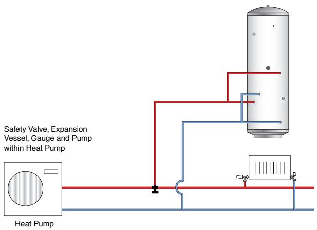
Schematic Open Vented Primary System
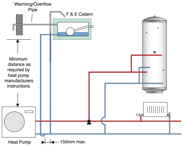

Note
The requirements for the control of legionella propagation in workplaces are described in the HSE Guide L8.
The hot water demand has the greatest influence on the performance of solar thermal installations for water heating. A proven relationship between tank volume and collector surface lies between 50 to 80 litres per m ^2 of collector surface.
Hot water secondary circulation increases the heat requirement for water heating and for very long piping lengths it can amount up to 100% of the heat requirement for water heating. Hot water circulation pumps should always therefore be time-and-temperature controlled.
5.5 Establishing the heat emitter temperatures
The temperature of the heat emitters at standard outside temperatures should not be higher than 55^ C, for MCS projects 50^ C at the design outdoor temperature. Recommended are underfloor systems with supply water temperatures of 35^ C and radiators with a supply water temperature of 50^ C. When replacing a conventional boiler heating system, with an Aquarea heat pump, the supply water temperature should be reduced as much as possible by installing additional thermal insulation and by taking redevelopment measures on the building. Conventional boiler heating systems are operated with supply water temperatures up to 75^ C. Through suitable redevelopment measures, existing radiators can often be operated at lower temperatures and therefore lower heat outputs. For this, refer to manufacturers' guidance for details of the output of the radiator at lower supply water temperatures.
If it is not possible to reduce the supply water temperature to 55^ C, it is also possible to use supply water temperatures of up to 65^ C by using the Aquarea HT series.
5.6 Operating mode and bivalence point
In order to avoid over-sizing and thus reduce investment costs, bivalent operation is generally preferred. In this case, below a defined outside temperature an additional heat source will be switched on. This heat source can be integrated externally (e.g. a gas boiler or stove with back boiler) or internally via the additional electric heater. If a heat source which produces heat from electric power is used, then this is termed (monoenergetic) operating mode.
In this bivalent operation, the air/water heat pump is only supported when the outside temperatures are very low. Because this is the case only for a few days per year, the heat generated by an additional heat source is only a few percentage of the overall generated energy.
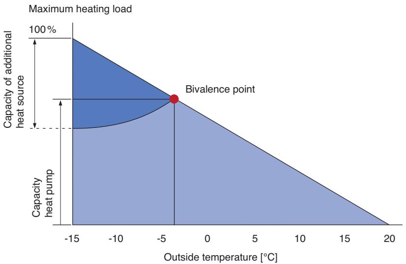
area
| Outside temperature [°C] | Capacity of additional heat source | Capacity of heat pump | | ------------------------ | ----------------------------------- | --------------------- | | -15 | 100% | 0 | | -10 | 100% | 0 | | -5 | 100% | 0 | | 0 | 100% | 0 | | 5 | 100% | 0 | | 10 | 100% | 0 | | 15 | 100% | 0 | | 20 | 100% | 0 |Bivalent parallel operating mode via an additional heat source

Note
The bivalence point is determined individually for each building (see for example the following section). By utilising its inverter technology, Aquarea heat pumps can operate efficiently even operating under part load without cycling. Nevertheless, it is recommended to select the bivalence point of the heat pump system above -10^ C.
For an installation to comply with Microgeneration Installation Standard (MIS) 3005, either the heat pump in monovalent mode or heat pump with additional heat source (excluding additional electric heater) integrated into a single control system must meet 100% of the calculated design space heating requirement.
5.7 Heat pump selection
5.7.1 General criteria
The selection of a suitable heat pump is made via the required heating capacity. In addition, the following decisions must be taken:
- Should a Bi-Bloc system or a Monobloc system be used?
- Should the heat pump be used just for heating or also for cooling?
- Should the heat pump be powered by a single phase or three phase supply (three phase units have higher coefficients of performance)?
5.7.2 What capacity is needed?
The main requirements on air/water heat pumps are determined using the calculated heating load to EN 12831 and outside design temperature. Furthermore, also the hot water heating and possible outages from the power company must be accounted for. Also the length of pipe between the outdoor unit and hydromodule (Bi-Bloc) as well as between the Monobloc unit and building must be considered because long pipe runs lead to loss of some heating capacity. Not only the capacity of the heat pump but also their supply water temperature at design outside temperature is important for correct selection of the heat pump.
Aquarea heat pumps have an additional electric heater which can provide extra heat supply in the event of very low outside temperatures.
All the above points must be considered together for the calculation of required heat pump capacity:
- Heating load (see section "Establishing the heating load and outside design temperature")
- Outside design temperature (see section "Establishing the heating load and outside design temperature")
- Hot water tank charging (required time for water heating with the heat pump)
- The power company's restrictions (if applicable, e.g. once per day for 2 hours)
- Pipe correction factor (see section "Planning Heat Source - Air" for consideration of losses through long pipe lengths)
Heat pump capacity ≥ heating load · 24h(24 h-tank charging time-power supplier outage time) · pipe correction factor

Note
In a new building, the building fabric generally dries out in the first two years after occupancy, whereby moisture from the construction phase escapes from the building fabric; in this phase, the heat requirement is higher than after the building has dried. This increase in heat requirement should be offset by the additional electric heater.
Example
- For a residential house in London, UK a required heating load of 9.6 kW and an outside temperature e = -1.5^
- Water heating for four people with a normal comfort level (45 litres per person and day at 45^ C tap temperature or 1.8 kWh): 4 Hence 1.8 = 7.2 kWh per day. A heat pump with a heating power of 9.6 kW would require an operating time of 7.2 kWh/9.6 kW = 0.75 h. Thus, if rounded up:
- The pipe correction factor, owing to a pipe length of 15 m (one-way length) with means of 1.0 and 0.83 results in line correction factor = 0.92
Tank charging = 1 h
Total heating capacity ≥ 9.6· 24h(24h - 1h)· 0.92 = 230.421.16 = 10.89kW
Factoring in power supplier outages of 2 hours per day:
Total heating capacity ≥ 9.6· 24h(24h - 1h - 2h)· 0.92 = 230.419.32 = 11.93kW
The calculated overall heating capacity must be calculated using a continuous water supply temperature of 35^ C for a underfloor heating system.

Note
The illustrated calculation of the overall heating load may differ slightly from the detailed calculation of the Aquarea Designer, but can still be used as a rule of thumb for fast calculation without the need of a calculation program.
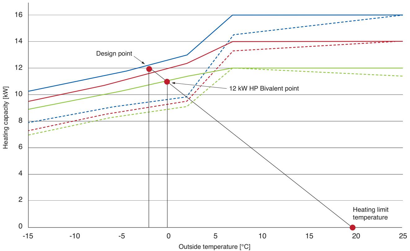
line
| Outside temperature [°C] | Heating capacity [kW] (Design point) | Heating capacity [kW] (12 kW HP Bivalent point) | | ------------------------ | ------------------------------------ | ----------------------------------------------- | | -2 | 12 | 9 | | 0 | 11 | 9 | | 20 | 0 | 12 |16kW (three phase)
14kW (three phase)
12kW (three phase)
Supply water temperature 35°C
Supply water temperature 55°C
Performance curves of the Aquarea-LT series for the Bi-Bloc systems with design point, heating limit temperature and bivalent point
This illustration shows the characteristic curve for the split systems of the Aquarea LT series with different flow temperatures giving different heating capacities at a given outdoor temperature. By plotting the design point (Heating capacity = 12 kW @ e = -2.0^ ) and the point at which there is no heating demand (Ambient external air temperature, in this example 20^ ) and then connect the two points. Where this line crosses the HP performance curve, this is the bivalent point.
For monovalent operation of the heat pump, the selected heat pump must provide a larger capacity than the design heating capacity. In the above example only the 16 kW heat pump at 35^ C flow temperature provides more capacity than required. (12.2 kW > 12 kW)
For reasons of economic viability or practicalities such as an existing heating system, the heat pump can be sized as a bivalent system. Using the 12 kW Aquarea-LT heat pump, a bivalence point of 0^ C is found. Below this outside temperature the heat pump will need support, whereas above this temperature the heat pump will run unsupported. In a bivalent alternative scheme, 0^ C is the switch over point.
The following heat pumps of the Aquarea-LT series, that are bi-bloc systems, come in to question due to the intersection point with the performance curve at 0^ C and at a supply water temperature of 35^ C:
| Heating and cooling | |
| single phase | WH-SDC12F6E5 |
| three phase | WH-SDC12F9E8 |
For an installation to comply with Microgeneration Installation Standard (MIS) 3005, the heat pump should be designed to run in monovalent mode or bivalent mode with additional heat source (excluding additional electric heater) integrated into a single control system to meet 100% of the calculated design space heating requirement.
5.8 Planning of installation room

Note
If you will be applying for Renewable Heat Incentive (RHI) financial support, your installation may have to have metering equipment fitted or be designed to be “meter-ready”. For more details, please see: www.microgeneration certification.org
When planning the installation room, all units and components of the heat pump system that are not installed outside the building must be considered:
• The Hydromodule (for the Bi-Bloc system)
- Pipes and wall passages should be thought out and arranged with short runs (electrical, refrigerant and heating pipes)
- Tanks (hot water tank as well as buffer tank if applicable)
Furthermore, attention must be paid so that the installation room is dry and free from frost and the maintenance work area is easily accessible.
5.8.1 Room volume for bi-bloc system
With a bi-bloc system, the refrigerant is partly inside the building, which must be considered with respect to minimum room volume. According to EN 378, the minimum required volume for a heat pump installation room ( V_min ) according to EN 378 T1 is calculated as follows:
$$ V _ {\min} = \frac {G}{c} $$
G = amount of refrigerant in kg
c = practical limit value in kg/m ^3 (for R410A c = 0.44 kg/m ^3 )
and for R407C c = 0.31 kg/m ^3 )

Note
The refrigerant and the amount of refrigerant differs for individual models and is dependent upon additional refrigerant filling that exceeds the pre-filled pipe length. Details on this can be derived from the technical data.

Attention
The refrigerant may not be mixed with or be replaced by a different type of refrigerant. Using a different refrigerant can lead to damage to the unit and also to safety problems.
The manufacturer assumes no responsibility and provided no guarantee for the application of refrigerants of a different type apart from R410A for the series Aquarea LT and T-CAP and R407C for the series Aquarea HT.
5.8.2 Assembly conditions and minimum distances from hydromodule
- No heat or steam source can be located near the hydromodule. Also laundry houses or other rooms with higher humidity are unsuitable, since high humidity leads to rust and can damage the unit.
- Adequate circulation of air must be provided inside the room.
- The condensate drained from the hydromodule should be easily channelled out because it can cause damage if not correctly drained. (if cooling is going to be delivered from heat pump)
- Noise inside the room should be considered.
- Do not install the unit near the door.
- The minimum distances (see Figure) must be observed.
- The hydromodule must be installed vertically on the wall, whereby the wall should be thick and dense so that no vibration occurs.
- In case electrical units are installed on wooden buildings with metallic or cable strips in accordance with the corresponding standards for electrical work, no electrical contacts are permitted between the unit and building.
- The hydromodule is only developed for internal installation and may not be installed outside.
Minimum distances from the hydro-module to walls, ceiling and floor
Note
The compressor is located in the outdoor unit of the bi-bloc system. The only noise from the hydromodule will solely come from circulation pump operation.
1 Minimum distance 300 mm
2 Minimum distance 600 mm
Example of an installation room with a hydromodule and hot water tank WH-TD20E3E5
Note
Because of an installation room volume of 6.25 m^3 in the example, it is suitable only for Aquarea LT single phase devices up to 9 kW heating capacity. The use of a device with a larger amount of refrigerant would exceed the practical limit value c (for R410A c = 0.44 kg/m^3 and for R407C c = 0.31 kg/m^3 )
1 Hot water tank
2 Hydromodule
3 Hot water
4 Cold water
5 Door
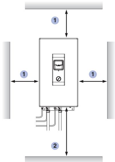
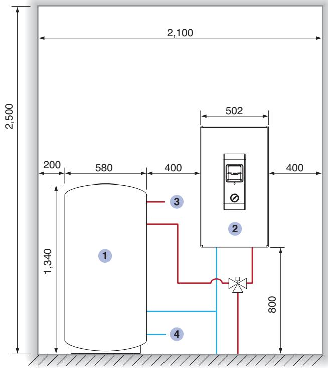
Side view
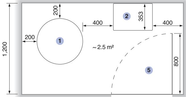
Top view
5.9 Planning heat source – air
Air to water heat pumps require planning permission in Wales and Northern Ireland but may be considered Permitted Development in Scotland and England, depending on the circumstances. Check with your local planning office to ensure you comply. Furthermore, besides the conditions listed in the following sections, attention must be paid so that when several outdoor or monobloc units (e.g. for heat pump cascades) are used, no short circuit of the exhaust air occurs (see Figure).
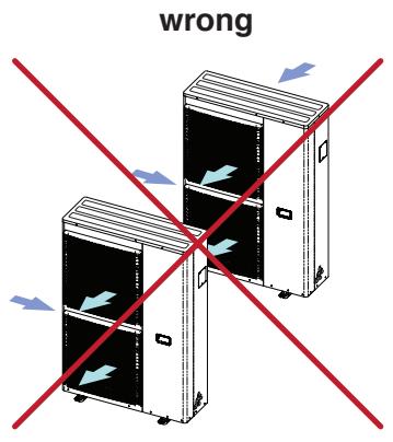
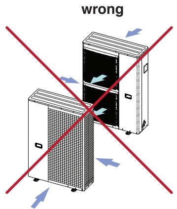
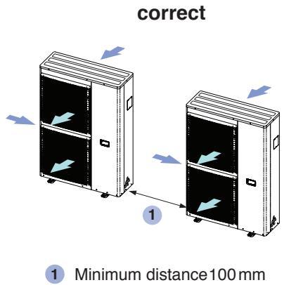
Correct arrangement of several outdoor or monobloc units
5.9.1 Bi-Bloc system
The bi-bloc system consists of an outdoor unit and a hydromodule. Depending on the capacity and model, the outdoor unit has one or two fans and differs in size (see Overview on Page 3). Generally, the following points must be observed for the distance between outdoor unit and hydromodule when using the bi-bloc system:
- In case the length of the refrigerant piping is greater than the pre-filled pipe length of the unit (depending upon model 10, 15 or 30 m, see Technical Data), additional refrigerant quantities specified in the technical data must be added.
- The maximum length of the refrigerant piping between hydromodule and outdoor device depending on model is 30 or 40 m (see Technical Data). This value may not be exceeded.
- The minimum length of the refrigerant piping between hydromodule and outdoor unit is 3 m and the installation may not fall short of this value.
- The maximum height difference between hydromodule and outdoor unit depending on model is 20 or 30 m (see Technical Data). This value may not be exceeded.
- The wall thickness of copper pipes for the refrigerant piping must be more than 0.8 mm.
Capacity decrease in long refrigerant pipe runs
The capacity of the bi-bloc systems decreases significantly with increasing length of the refrigerant pipe runs. The capacity reduces depending on the heat pump's nominal capacity, either up to 12 kW nominal capacity or 14 and 16 kW nominal capacity (see Table).
| Pipe length of refrigerant (one-way) | up to 10m | up to 20m | up to 30m |
| Pipe correction factor | 1.0 | 0.83 | 0.77 |
Pipe correction factors for consideration of the reduced heat pump heating capacity during the selection of the heat pump for bi-bloc systems with up to 12kW nominal capacity
| Pipe length of refrigerant (one-way) | up to 7 m | up to 10 m | up to 20 m | up to 30 m | up to 40 m |
| Pipe correction factor | 1.0 | 0.91 | 0.87 | 0.83 | 0.77 |
Pipe correction factors for consideration of the reduced heat pump heating capacity during the selection of the heat pump for bi-bloc systems with 14 and 16 kW nominal capacity
Assembly conditions and minimum distances around outdoor unit
- The heat output of the outdoor unit may not be prevented by additional protection apparatus like sun blind or similar.
- Locations at which the outside temperature decreases below -20°C must be avoided.
- The minimum clearances (see figure on following page) must be observed.
- A drainage system using a drainage pipe leading to a gravel bed in the frost-free subsoil is recommended for draining melt water in de-icing mode (see installation example).
- Objects that can lead to short circuit of exhaust air must not be erected.
- The operational noise emission of the outdoor unit should not lead to irritation of the users or neighbours.
- If the outdoor unit is installed near the sea, in regions with a high content of sulphur or at oily locations (e.g. machine oil, etc.), its operational service life will be possibly shortened.
- The outdoor unit is to be installed on a concrete foundation or on a stable base frame e.g. on a building external wall, aligned horizontally, and fastened with bolts (ø 10 mm).
- Use additional vibration-damping rubber buffers for decoupling.
- For installation locations that can be influenced by strong winds e.g. when a wind blows between buildings, including building roofs, the outdoor unit must be secured on the building by means of an additional protection against toppling (e.g. cable).
- The hydromodule is only developed for internal installation and may not be installed outdoors.
Minimum distances from the outdoor unit to the neighbouring walls and objects with representation of air flow direction. The connection of the refrigerant piping can occur in one of four directions (front, rear, side, down).
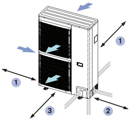
1 Minimum distance 100 mm
2 Minimum distance 300 mm
3 Minimum distance 1,000 mm
Fastening the outdoor unit
The outdoor unit must be installed on a flat, level and solid surface. The weight of the water in addition to the weight of the unit must be taken into consideration. Four M12 anchor bolts with a pull-out force greater than 15,000 N are required for fastening.
Minimum requirements for anchoring the outdoor unit to the floor or a foundation (left) or directly to a base plate (right).
* Different for 3 kW and 5 kW units (see dimensioned drawing)
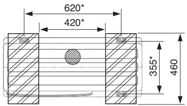
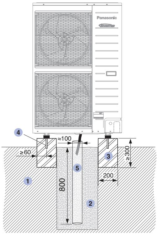
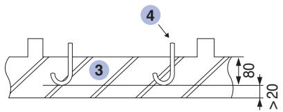
1 Base
2 Gravel
3 Strip foundation or base plate
4 Anchor bolt
5 Drainage pipe
All dimensions in mm
5.9.2 Monobloc system
The monobloc system consists of a unit containing one or two fans, depending on the power class and model. The units differ in physical size (see overview on page 3).
The water pipes between the monobloc unit and the building are heat distribution pipes that are laid directly adjacent to the outdoor air. According to the current energy-saving directive (EnEV 2014), these pipes are to be thermally insulated with a least twice the minimum thickness as per Annex 5, Table 1, Lines 1 to 4, but with a thickness of at least 40 mm, based on a thermal conductivity of 0.035 W/(m × K) .

Attention
In monobloc systems, there is a risk of freezing if the heating circuit is filled with water and the outside temperature falls below +4°C.
That can cause significant damage to the device.
Freezing must be prevented on-site through one of the following measures:
- The heating circuit is operated using a foodstuff compatible anti-freeze mixture (propylene glycol).
- An auxiliary heater unit in the monobloc unit prevents the heating circuit freezing.
- The heating circuit is drained by a system to be provided by the customer (manual or automatic).

Note
For details on preventing water pipes freezing, and heat and cold protection, see the Guidelines BS 5422 and BS 5970.
Assembly conditions and minimum distances from monobloc unit
- The heat output of the monobloc unit may not be prevented by additional protection apparatus like sun blind or similar.
- Locations at which the outside temperature decreases below -20°C must be avoided.
- The minimum clearances (see figure) must be observed.
- A drainage system using a drainage pipe leading to a gravel bed in the frost-free subsoil is recommended for draining melt water in de-icing mode (see installation example on page 80).
- Objects that can lead to short circuit of exhaust air must not be erected.
- The operational noise emission of the monobloc unit should not lead to irritation of the users or neighbours.
- Use additional vibration-damping rubber buffers for
- If the monobloc unit is installed near the sea, in regions with a high content of sulphur or at oily locations (e.g. machine oil, etc.), its operational service life will be possibly shortened.
- For installation locations that can be influenced by strong winds e.g. when a wind blows between buildings, including on building, the Monobloc unit must be secured on the building by means of an additional protection against toppling (e.g. cable).
- The monobloc unit is only developed for outdoor installation and may not be installed outdoors.
- Condensate should be able to be drained from the unit without difficulty.
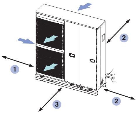
1 Minimum distance 100 mm
2 Minimum distance 300 mm
3 Minimum distance 1,000 mm
Minimum distances from the Monobloc unit to the neighbouring walls and objects with representation of air flow direction.
Fastening of the monobloc unit
The monobloc unit must be mounted on one level, horizontal and on a solid surface. Besides the weight of unit, also the weight of water must be considered. Four anchoring bolts M12 are needed for fastening, where the tightening force is minimum 15,000 N.
Minimum requirements for anchoring the Monobloc unit to the floor or a foundation (left) or directly to a base plate (right)
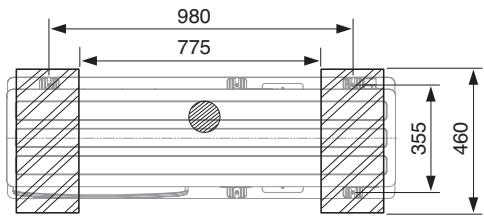
1 Base
2 Gravel
3 Strip foundation or base plate
4 Anchor bolt
5 Drainage pipe
All dimensions in mm
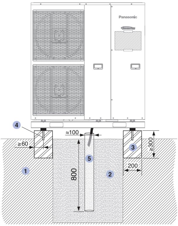
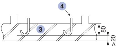
5.10 Acoustics
5.10.1 Sound pressure level
Sound occurs when air vibrates. This vibration propagates in air as pressure waves and reaches the ear drum of the human ear. Independent of the type of noise (speech or motor noise) the sound can be measured as sound pressure. The larger the sound pressure, the louder the noise is perceived. The human ear can perceive a range from 20 × 10^-6 Pa (hearing threshold) up to 20 Pa (threshold of pain). This range that corresponds to a ratio of 1:1,000,000 is not perceived by the human ear linearly, but rather logarithmically. For this reason the sound pressure is not specified as pressure, but rather as sound pressure level in decibel (dB). Values of sound pressure level for typical situations are:
| Noise | Sound pressure level in dB(A) | Sound pressure in μPa | Perception |
| Forest | 20 | 100 | very quiet |
| Library | 40 | 1,000 | quiet |
| Speech | 55 | 10,000 | normal |
| Street | 80 | 100,000 | loud |
| Pneumatic hammer | 100 | 1,000,000 | very loud |
Typical noise situations and occurring sound pressure levels and sound pressures
The non-linear perception of sound pressure leads to a state where two equally loud sound sources are not perceived as double as loud as one sound source but only 3dB louder. Doubling of the volume of a noise source is associated with a sound pressure level increase by 10dB.
The effect of other nearby noise influences will alter the perceived noise limit values. The following table can therefore only act as a guide of noise limits for each type of area:
| Industrial areas | Day and night | 70 dB(A) |
| Commercial areas | Day time | 65 dB(A) |
| Night time | 50 dB(A) | |
| Core areas | Day time | 60 dB(A) |
| Night time | 45 dB(A) | |
| General residential areas | Day time | 55 dB(A) |
| Night time | 40 dB(A) | |
| Pure residential areas | Day time | 50 dB(A) |
| Night time | 35 dB(A) | |
| Health resort areas, hospitals | Day time | 45 dB(A) |
| Night time | 35 dB(A) |
The values are based on the measurable value 0.5m in front of the middle of an opened window of the affected room to be protected. They are only valid as mean values and may be exceeded by temporary noise peaks.
The measurable sound pressure level is dependent on the distance to the sound source and decreases with increasing distance.
5.10.2 Sound power levels for estimation of sound pressure level
The sound power level is a quantity for evaluating the sound source independently of distance and direction of sound propagation. It is a calculable quantity that is determined for individual units in laboratory measurements under defined conditions. Based on the sound power level of a specific unit the sound pressure level can be estimated at a certain distance and for corresponding sound propagation conditions for a certain case.
Sound propagates in all directions equally with the sound power from the sound source. With an increasing distance to the sound source, the area through which the sound penetrates expands in proportion to the distance from the sound source. This leads to a continuous decrease of the sound pressure level for a constant sound power. During sound propagation the sound pressure level is moreover influenced by the following factors:
- Interruption by obstructions like buildings, walls or landscape formations
- Reflection from surfaces such as walls, glass facades, buildings or asphalt-covered areas as well as areas made of stone
- Absorption of sound on e.g. grass, bark-chip mulch, leaves or fresh-fallen snow
- Wind can increase or decrease the sound pressure level (depending on wind direction).
An estimation of the sound pressure level L_Aeq at a certain place with a distance r from the heat pump can be calculated with the following formula based on the sound power level L_WAeq :
$$ L _ {A e q} = L _ {W A e q} + 1 0 \times \log \left(\frac {Q}{4 \times \pi \times r ^ {2}}\right) $$
For this, one additionally needs the direction factor Q, which considers the spatial radiation conditions of the sound source:
| Sound propagation | Half space | Quarter space | Eighth space |
| Q= | 2 | 4 | 8 |
| Arrangement |  |  | 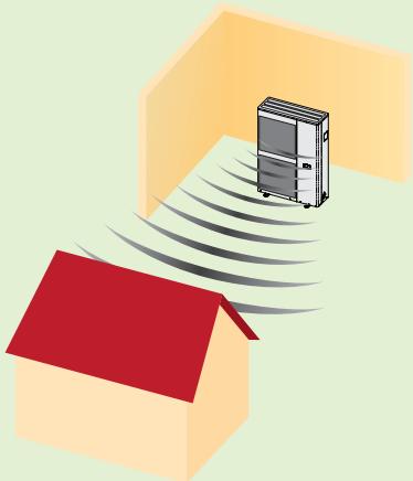 |
 |  |
Directional factor Q for different arrangements of the sound source
Example
The outdoor unit WH-UD12FE5 of a bi-bloc system has a sound power level of 67 dB(A) and is installed such that the sound can propagate into the quarter space (Q=4). The sound pressure level as 10 m distance results in:
$$ \mathrm{L} _ {\mathrm{Aeq}} (1 0 \mathrm{m}) = 6 7 \mathrm{dB(A)} + 1 0 \times \log \left(\frac {4}{4 \times \pi \times 1 0 ^ {2}}\right) = 4 2 \mathrm{dB(A)} $$
For a distance of 20 m the sound pressure level is still:
$$ \mathrm{L} _ {\mathrm{Aeq}} (2 0 \mathrm{m}) = 6 7 \mathrm{dB(A)} + 1 0 \times \log \left(\frac {4}{4 \times \pi \times 2 0 ^ {2}}\right) = 3 6 \mathrm{dB(A)} $$
The sound pressure level can be determined roughly from the following table, in that the table value is subtracted from the unit specific sound power level (see technical data).
| Directivity factor Q | Distance from the sound source in m | ||||||||
| 1 | 2 | 4 | 5 | 6 | 8 | 10 | 12 | 15 | |
| 2 | -8 | -14 | -20 | -22 | -23,5 | -26 | -28 | -29,5 | -31,5 |
| 4 | -5 | -11 | -17 | -19 | -20,5 | -23 | -25 | -26,5 | -28,5 |
| 8 | -2 | -8 | -14 | -16 | -17,5 | -20 | -22 | -23,5 | -25,5 |
Table for rough calculation of the sound pressure level based on the sound power level.

Note
Through the selection of the installation location, the sound pressure level can be increased or decreased. Installation on reflective floor surfaces should be avoided. Sound pressure level can be reduced further by constructing obstructions, whereby the air flow itself should not be obstructed.
The sound output direction of outdoor and/or monobloc units should be selected if possible towards the street, since neighbouring rooms to be protected are seldom oriented in this direction.
In case of doubt, an acoustic engineer must be consulted.
5.11 Cooling
Old Models: Aquarea heat pump models with cooling mode are manually switched over from the heating mode into the cooling mode and must be switched over into the heating mode again after the end of the cooling period.
New models: AUTO can be used to switch between HEAT and COOL automatically. Switch over points need to be set during commissioning.
5.11.1 Cooling with underfloor heating
Underfloor heating systems are in principle suitable for the cooling mode, however, they cannot be operated with very low supply water temperatures, because both the comfort decreases as well as the danger of negatively exceeding the dew point. The surface temperature is limited generally to minimum 20^ C. For a delta-T between supply and return water temperatures of 3 to 4 K a specific cooling capacity of maximum 30 to 40 W/m^2 can be attained. The cooling capacity is essentially influenced by pipe length and pipe diameter in the underfloor heating system as well as the floor covering. For a tile covered floor the thermal transfer is significantly better than e.g. carpeted floor, which negatively influences the cooling capacity.
Due to the limits on cooling capacity of underfloor heating systems, the room cooling cannot be controlled to a fixed room temperature. At least the supply water temperature must be set, which prevents the dew point from being negatively exceeded.
5.11.2 Cooling with fan convectors
Fan convectors can be operated with much lower supply water temperatures than underfloor heating systems ie 5°C. Accordingly, the achievable cooling capacity of fan convectors is greater and a greater level of comfort is achievable than with underfloor heating systems. Owing to low supply water temperatures closed-cell insulation of the piping as well as an integration of the condensate outlet to the building's waste water system or another suitable outlet must be considered with the application of fan convectors for room cooling.

Attention
In the cooling mode, condensation of moisture in the air can occur on the surface of the heat transfer systems when the temperature falls below the dew point. This can lead to damage to the building or also to danger of slipping on the floor surfaces.
The effects of the temperature falling below the dew point must therefore be ruled out by means of suitably placed dew point sensors or the condensate occurring must be drained safely. The affected piping must be insulated tightly against condensation.
5.12 Electrical connection
5.12.1 Power supply
The Aquarea heat pump range contains models specific to either a single phase of three phase electrical connection. Depending on the nominal heating capacity and the capacity of the additional electric heater, individual models differ in the number of mains connections. Models up to 9 kW nominal capacity are available with two mains connections and models with 12 to 16 kW with three mains connections.
| Electrical connections for the bi-bloc systems | |||
| 3 to 5kW(single phase) | Additional electric heater andelectric immersion heater  Power supply 2 Power supply 2 | Hydro module andoutdoor unit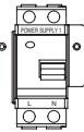  Power supply 1 Power supply 1 | [F4CXK] Connecting the indoor/outdoor unit Connecting the indoor/outdoor unit |
| 7 to 9kW(single phase) | Hydro module, outdoor unitand additional electric heater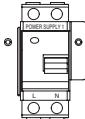  Power supply 1 Power supply 1 | Electric immersion heaterand additional backup heater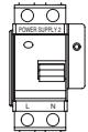  Power supply 2 Power supply 2 | [F4CXK]Connecting the indoor/outdoor unit |
| 12 to 16kW(single phase) | Hydro module andoutdoor unit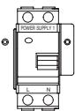  Power supply 1 Power supply 1 | Additional electric heater andelectric immersion heater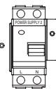  Power supply 2 Power supply 2 | [F4CXK]Connecting the indoor/outdoor unit |
| 9kW(three phase) |  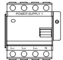 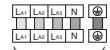 Power supply 1 Power supply 1 |    Power supply 2 Power supply 2 | [F4CXK]Connecting the indoor/outdoor unit |
| 12 to 16kW(three phase) | 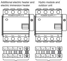 Power supply 2 Power supply 2 | 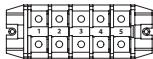 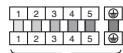 Power supply 1 Power supply 1 | [F4CXK]Connecting the indoor/outdoor unit |
Power supply 1
Connecting the indoor/outdoor unit
12 to 16 kW (three phase)
Power supply 2
Power supply 1
Connecting the indoor/outdoor unit
Differences of electrical connections for bi-bloc systems, different phases and nominal heating capacities.
With the monobloc system, the mains connection is provided directly on the monobloc unit. With the bi-bloc system the mains connection is provided on the hydromodule, whereby the power supply of the outdoor unit is provided via an additional connection between the hydromodule and outdoor unit. An overview of the above-mentioned differences is depicted in the following table. The required cross-sections can be derived from the technical data.
| Electrical connections for the monobloc systems | |||
| 5 to 9kW(single phase) | Compact system 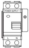 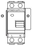 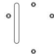   Power supply 1 Power supply 2 Power supply 1 Power supply 2 | Fault-current protective switchMains connections | |
| 12 to 16kW(single phase) | Compact system 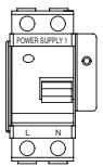 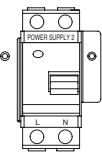 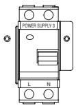    Power supply 1 Power supply 2 Power supply 3 Power supply 1 Power supply 2 Power supply 3 | Fault-current protective switchMains connections | |
| 9kW(three phase) |  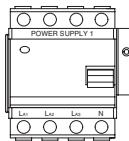  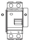 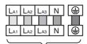   Power supply 1 Power supply 2 Power supply 1 Power supply 2 | Fault-current protective switchMains connections | |
| 12 to 16kW(three phase) | 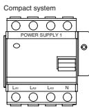 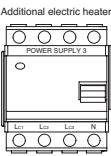 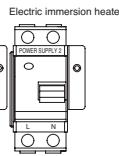 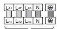 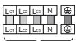  Power supply 1 Power supply 3 Power supply 2 Power supply 1 Power supply 3 Power supply 2 | Fault-current protective switchMains connections | |
Power supply 1
Power supply 3
Power supply 2
Differences of electrical connections for monobloc systems, different phases and nominal heating capacities.
Phase-out models
Electrical connections for the bi-bloc systems
| 7 to 9kW(single phase) | Additional electric heater andelectric immersion heater 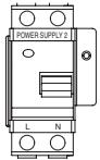 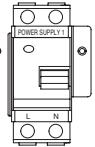   Power supply 2 Power supply 1 Power supply 2 Power supply 1 | Hydro module andoutdoor unit 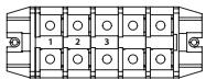 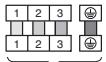 Connecting the indoor/outdoor unit Connecting the indoor/outdoor unit | Fault-currentprotective switchMains connections | ||
| 12 to 16kW(single phase) | 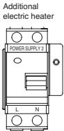 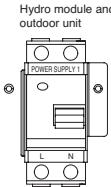   Power supply 2 Power supply 1 Power supply 2 Power supply 1 | 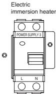  Power supply 3 Connecting the indoor/outdoor unit Power supply 3 Connecting the indoor/outdoor unit | Fault-currentprotective switchMains connections | ||
| 9kW(three phase) | Hydro module, outdoor unitand additional electric heater [Ld Ld Ld N] [Ld Ld Ld N] [Ld Ld Ld N] [Ld Ld Ld N] [Ld Ld Ld N] [Ld Ld Ld N] [Ld Ld Ld N] [Ld Ld Ld N] [Ld Ld Ld N] [Ld Ld Ld N] [Ld Ld Ld N] [Ld Ld Ld N] | Electricimmersion heater [Ld Ld Ld N] [Ld Ld Ld N] [Ld Ld Ld N] [Ld Ld Ld N] [Ld Ld Ld N] [Ld Ld Ld N] [Ld Ld Ld N] [Ld Ld Ld N] [Ld Ld Ld N] [Ld Ld Ld N] [Ld Ld Ld N | Fault-currentprotective switchMains connections | ||
| 12 to 16kW(three phase) | Additionalelectric heater [Ld Ld Ld N] [Ld Ld Ld N] [Ld Ld Ld N] [Ld Ld Ld N] [Ld Ld Ld N] [Ld Ld Ld N] [Ld Ld Ld N] [Ld Ld Ld N] [Ld Ld Ld N] [Ld Ld Ld N] [Ld Ld Ld N | Electricimmersion heater [Ld Ld Ld N] [Ld Ld Ld N] [Ld Ld Ld N] [Ld Ld Ld N] [Ld Ld Ld N] [Ld Ld Ld N] [Ld Ld Ld N] [Ld Ld Ld N] [Ld Ld Ld N] [Ld Ld Ld N] [Ld Ldr Ldr N] [Ld Ldr Ldr N] [Ld Ldr Ldr N] [Ld Ldr Ldr N] [Ld Ldr Ldr N] [Ld Ldr Ldr N] [Ld Ldr Ldr N] [Ld Ldr Ldr N] [Ld Ldr Ldr N] [Ld Ldr Ldr N] [Ld Ldr Ldr N] [Ld Ldr LdrN] [Ld Ldr Ldr N] [Ld Ldr Ldr N] [Ld Ldr Ldr N] [Ld Ldr Ldr N] [Ld Ldr Ldr N] [Ld Ldr Ldr N] [Ld Ldr Ldr N] [Ld Ldr Ldr N] [Ld Ldr Ldr N] [Ld Ldr Ldr N] [Ld Ldr Ldr N | Fault-currentprotective switchMains connections | ||
Bi-Bloc systems (phase-out models) have different electrical connections, a different number of phases and different rated heating power
5.12.2 Connections to the inputs and outputs
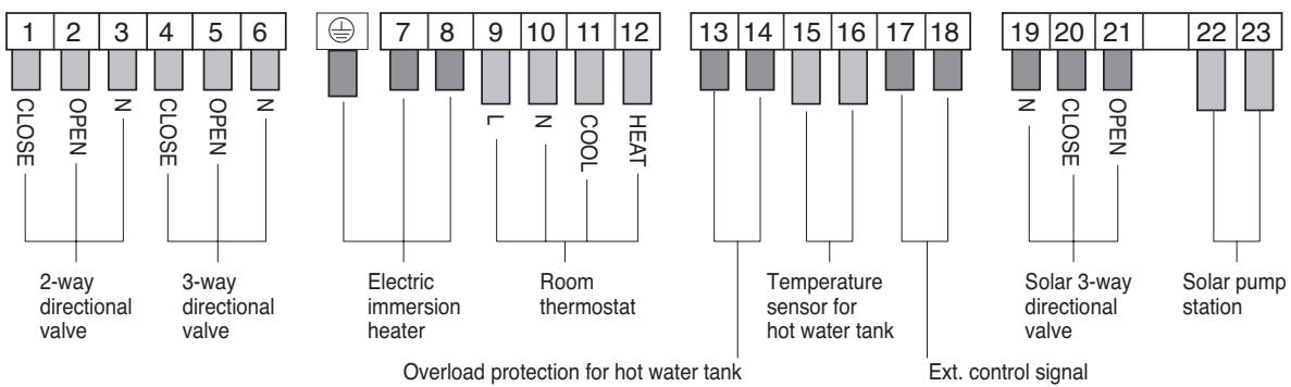
flowchart
graph TD
    A["1"] --> B["CLOSE"]
    C["2"] --> D["OPEN"]
    E["3"] --> F["Z"]
    G["4"] --> H["CLOSE"]
    I["5"] --> J["OPEN"]
    K["6"] --> L["Z"]

    M["7"] --> N["Electric immersion heater"]
    O["8"] --> P["L"]
    Q["9"] --> R["Z"]
    S["10"] --> T["COOL"]
    U["11"] --> V["HEAT"]

    W["12"] --> X["Room thermostat"]

    Y["13"] --> Z["Temperature sensor for hot water tank"]
    AA["14"] --> AB["Hot Water Tank"]
    AC["15"] --> AD["Hot Water Tank"]
    AE["16"] --> AF["Hot Water Tank"]
    AG["17"] --> AH["Hot Water Tank"]
    AI["18"] --> AJ["Hot Water Tank"]

    AK["19"] --> AL["Solar 3-way directional valve"]
    AM["20"] --> AN["Solar pump station"]
    AO["21"] --> AP["Solar pump station"]
    AQ["22"] --> AR["Solar pump station"]
    AS["23"] --> AT["Solar pump station"]
| Terminals | Connection | Function | Condition | Cable cross-section |
| 1 to 3 | 2-way directional valve | Output for the activation of the 2-way directional valves (e.g. for underfloor heating system, cooling) | 3×min.0.5mm2 | |
| 4 to 6 | 3-way directional valve | Output for the activation of the 3-way directional valves (e.g. for heating, hot water tank) | 5: Tank, 4: Heat | 3×min.0.5mm2 |
| Earth to 8 | Electric immersion heater | Output for switching on/off the electric immersion heater | The maximum power of the hot water electric immersion heater should be maximum 3kW | 3×min.1.5mm2 |
| 9 to 12 | Room thermostat | Input for room thermostat signals | 4 and/or 3×min.0.5mm2 | |
| 13 to 14 | Overload protection for hot water tank | Input for overload protection of the hot water tank volt free | Terminals 13/14 must be bridged when no overload protection is used for the hot water storage | 2×min.0.5mm2 |
| 15 to 16 | Temperature sensor for hot water tank | Input for temperature sensor of the hot water tank | 2 Kohlms @ 25°C NTC | 2×min.0.5mm2 |
| 17 to 18 | Ext. control signal | Input for external control signal volt free | These two terminals are bridged during delivery. Connection: 1-pole (min. 3mm contact gap) | 2×min.0.5mm2 |
| 19 to 21 | Solar 3-way directional valve | Output for activation of the solar 3-way directional valve | Additional solar PCB required | 3×min.0.5mm2 |
| 22 to 23 | Solar pump station | Input of the ON signal of Solar pump 2 (230 VAC) | Use additional circuit board CZ-NS1P, CZ-NS2P or CZ-NS3P | 2×min.0.5mm2 |


Terminal strip and table of the input and outputs with function
Note
For easy connection of a hot water tank provided by the customer, Panasonic offers a temperature sensor installation kit for a foreign tank. This article bears the designation CZ-TK1.
The outside temperature sensor is located in the outdoor or monobloc unit and must not be installed or connected because the measured values are transmitted via an internal BUS line.
5.12.3 DNO and tariffs
For the connection of the heat pump to the power mains, consideration of the District Network Operator (DNO) connection conditions is required. With this connection, data about the heat pump and operating parameters must also be specified. If there is the option of using a cheaper split tariff, this should be carefully considered to take into account the hot water and heating run times and the building heat loss. This should be considered at the planning stage to ensure the appropriateness of using a split tariff.

Attention
If an outage from the power supply company coincides with a frost period, then frost damage can occur if the frost protection measure selected requires electricity. An auxiliary heating unit or other frost protection devices are therefore need to be connected to the power mains such that they are not affected.

Note
For more details on how these arrangements affect UK subsidy requirements, please see: www.microgenerationcertification.org
5.13 Hydraulics
5.13.1 Hydraulic integration
All Aquarea heat pump systems have an internal water circulation pump that circulates the heating water through the heat exchanger system. A standard pump or high-efficiency pump is used depending on the series and model variant of the Aquarea heat pump. Due to the independent control of the high-efficiency pumps, standard and high-efficiency pumps must be handled differently with regard to the hydraulic decoupling of the heat pump circuit and heat consumer circuit (see following sections).

Attention
Depending on the series and model version, Aquarea heat pumps are delivered with standard or high efficiency pumps.
High efficiency pumps have internal speed control, which can cause the volume flow to drop below the minimum volume flow depending on the setting. If this is not taken into consideration, it can lead to error messages.
Note the explanations on hydraulic decoupling for standard and high efficiency pumps.

Note
Units with high-efficiency pumps are specially labelled in the unit overview at the start of the document and in the technical data. Generation F units have high-efficiency pumps without differential pressure control and can be integrated into the hydraulic system in the same manner as standard pumps.
Hydraulic decoupling for standard pumps and high-efficiency pumps without differential pressure control
In individual cases, one or more water circulation pumps may be needed for the respective heating circuits in addition to the device-internal water circulation pump. If this is the case, the heat pump circuit and the heat emitter circuit must be hydraulically decoupled via a buffer tank or a hydraulic switch (low loss header). When integrating without hydraulic decoupling, it must be ensured that the minimum circulation specified for the respective heat pump (see technical data) is maintained at all times. Automatic mixers or thermostatic valves can restrict the hot water circulation to such an extent that the flow falls below the minimum circulation. To prevent this, Panasonic recommends always combining heat transfer systems without hydraulic decoupling with an auto-bypass valve between the heating supply flow and return flow. The auto-bypass valve must be designed for the nominal volume circulation of the respective heat pump.
Hydraulic decoupling for high-efficiency pumps with differential pressure control
In contrast to standard pumps, high-efficiency pumps with differential pressure control have an independent controller. If the resistance in the heating circuit increases, e.g. because thermostatic valves close, the high efficiency pump detects an increased differential pressure and automatically reduces the speed and volume flow. That ensures that the water circulation pump does not consume electricity unnecessarily. The pump supplies the heat transfer system with a lower volume flow until the valves re-open and the speed increases automatically due to the decreasing differential pressure until the nominal volume flow or the target differential pressure is reached.
The high-efficiency pumps with differential pressure control used in the Aquarea heat pumps have two control modes that can be set at the pump.
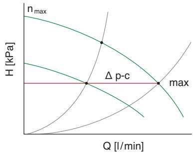
line
| Q [l/min] | H [kPa] | | --------- | ------- | | 0 | 0 | | Δp-c | Δp-c | | max | max |Δ p-c – constant differential pressure:
The electronic system holds the differential pressure target to be maintained by the pump at the value set (level 1 to 7) up to the maximum point. Panasonic recommends this type of control.

line
| Q [l/min] | H [kPa] | | --------- | ------- | | 0 | max | | Q = -2.5 | Δp-v | | Q = -1.5 | n_max | | Q = 0 | max |p-v – variable differential pressure:
The electronic system changes the differential pressure target to be maintained by the pump (configurable between levels 2 to 6), whereby the differential pressure decreases simultaneously with the volume flow to max. half of the differential pressure target.
| Both types of control reduce the pump speed when the differential pressure or resistance in the heating circuit increases. As a result, the volume circulation decreases to a far greater extent than with unregulated standard pumps, and can cause the volume flow to drop below the minimum (see technical data) and thus to a fault. | ||
Attention | In contrast to standard pumps and pumps without differential pressure control, a hydraulic decoupling must be established between the heat pump circuit and heat consumer circuit when using Aquarea heat pumps with high-efficiency pumps – auto-bypass valves cannot be used. | |
| In-line Filter/Strainer | As an alternative to hydraulic decoupling via a hydraulic switch or a buffer tank, it can be implemented via a bypass using multiple non-restrictable or permanently open heating circuits.Rooms with continuous high heating requirements such as bathrooms are suitable for this. When using this option, you must also ensure that the minimum volume flow of the heat pump is always guaranteed. | |
| Magnetic Particle Filter | Prior to connecting the return pipe to the heat pump, an in-line filter/strainer must be installed on the building side to protect the heat pump. The mesh size of the in-line filter/strainer must be minimum 500 to 600 μm (micron), whereby the pressure loss though the installation of the dirt filter may not impair the operation of the heat pump. Failure to fit an in-line filter on install will invalidate the warranty, as well as cause permanent damage to the heat pump unit. | |
| System volume | A magnetic particle filter is also recommended to be fitted to the system but is not a mandatory requirement, BUT a magnetic particle filer is not to be fitted in place of an inline filter only in addition to one. | |
| Depending on the nominal heating capacity of the heat pump system the following total water volume in the system must be available:Nominal heating capacity up to incl. 9kW: 30 litresNominal heating capacity 12kW up to incl. 16kW: 50 litres | ||
Note | If the total water volume in the system is lower than the specified values, the system water volume must be increased using a buffer tank or an additional vessel. | |
5.13.2 Pumping height and pipe network resistance
The device-internal water circulation pump of Aquarea heat pumps differs in delivery height and delivery volume according to the series and model version. In addition, there are distinctions between standard pumps, high-efficiency pumps without differential pressure control and high-efficiency pumps with differential pressure control (see also unit overview at the start of the document and the technical data).
While standard pumps have fixed configurable pump levels, high efficiency pumps have automatic speed control with a finer pump level setting option, which results in different pump curve characteristics (see the following sections).
When designing the pump delivery head, all components of the piping network and their individual resistances must be incorporated at their rated volume flow. Components like mixers, valves and heat meters must be selected so that the rated flow matches the rated volume flow of the heat pump system.
Tipp 1: Note the rated volume flow
For efficient heat generation, heat pumps work with a spread between the supply and return flows of approx. 5K. That distinguishes them from heat generators with burners, which can easily cope with a spread between the supply and return flows of roughly 10 or 20K. The low temperature spread of heat pumps means that the volume flow of heat pumps is generally higher than heat generators with burners for transporting the same heat output. When planning, you must therefore pay particular attention to the rated volume flow and the resulting resistance of the pipe network.
Pump speed 3
Pump speed 2
Pump speed 1
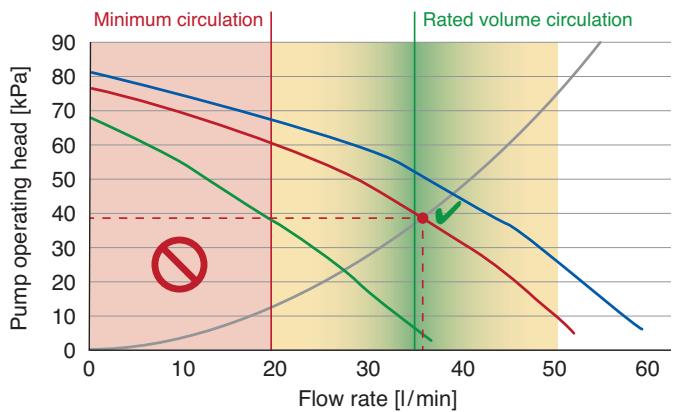
line
| Flow rate [l/min] | Pump operating head [kPa] (Minimum circulation) | Pump operating head [kPa] (Rated volume circulation) | | ----------------- | ----------------------------------------------- | ------------------------------------------------------ | | 0 | 80 | 70 | | 20 | 60 | 40 | | 35 | 40 | 40 | | 50 | 20 | 80 | | 60 | 10 | 90 |Sample pipe network resistance characteristic curve with a correctly set rated volume circulation at pump level 2 (standard pump) for the WH-MXF12D6E5
Tipp 2: Note the rated pipe diameter
The pressure drop in the pipelines increases exponentially with the volume circulation. That means that doubling the rate of circulation increases the pressure drop by a factor of 4! This is due to the circulation speed in the pipe, which depends on the rate of circulation and the internal pipe diameter.
As an alternative to pipe network calculations, the pressure drop in pipe sections can be determined via nomograms. The following applies as a recommendation for designing main distribution lines:
• The circulation speed should be between 0.3 to max. 1.5 m/s
- The pressure drop per metre should be roughly 0.1 kPa/m
Based on these criteria, the required rated pipe diameter can be read from the copper pipe nomogram (see example). The recommended range is highlighted in colour. In order to determine the pipe network resistance of an entire line, the pressure drop per metre must be multiplied by the length of the respective sub-sections, and the pressure drop of the sub-sections must be added. The total resistance of a line is calculated from the total pressure drop of the sub-sections multiplied by an estimated supplementary factor of 1.5.
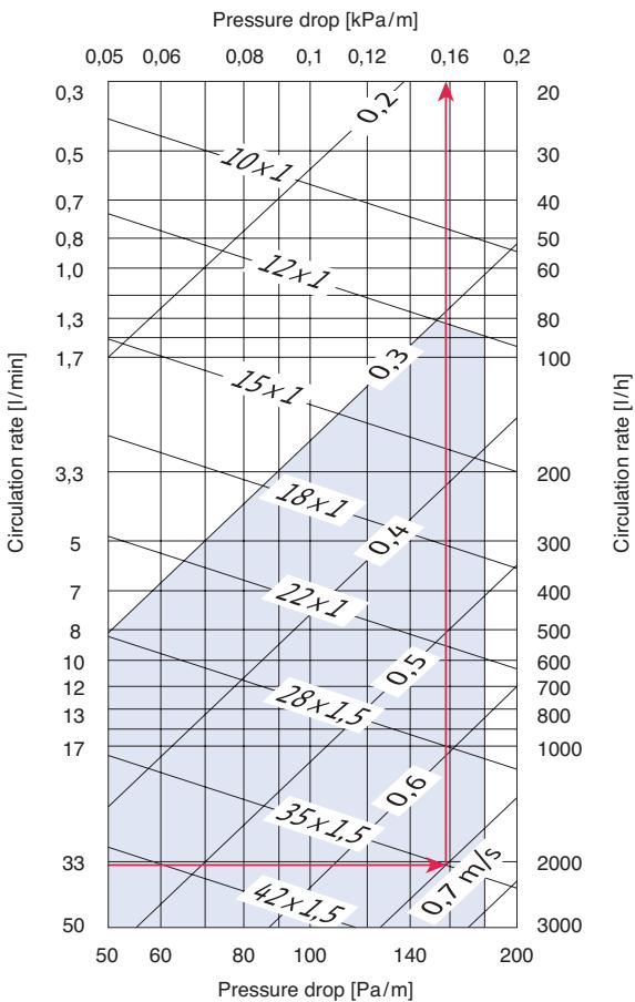
Copper pipe nomogram
Sample calculation of the rated pipe diameter for the WH-MXF12D6E5 with a rated volume flow of 34 l/min: This results in a rated copper pipe width of 35 × 1.5 at a pressure drop of 0.16 kPa/m and a circulation speed of 0.7 m/s
5.13.3 Pumping height
The device-internal water circulation pump of Aquarea heat pumps differs in delivery height and delivery volume according to the series and model version. In addition, there are distinctions between standard pumps, high-efficiency pumps without differential pressure control and high-efficiency pumps with differential pressure control (see also unit overview at the start of the document and the technical data). Whereas standard pumps and high-efficiency pumps without differential pressure control have definable fixed pumping levels, high-efficiency pumps with differential pressure control have an independent speed control system with finer adjustment possibilities of the pumping levels, which results in a different pump characteristic curve (see following sections).
For dimensioning the pump operating head, all components of the piping individual resistances must be considered for nominal circulation rate. Components like mixer valves and heat meters must be selected such that the nominal circulation rate is matched to the nominal circulation rate of the heat pump system.

Attention
The sum of individual resistances of all components of the network of pipes may not exceed the pump head under nominal rate of circulation. If the resistance of the network of pipes is too high, the nominal rate of circulation cannot be attained by the internal water circulation pump. The heat pump control system will register that the minimum circulation rate is not attained and therefore indicate malfunction.
Pumping height standard pumps
Pump speed 3
Pump speed 2
Pump speed 1
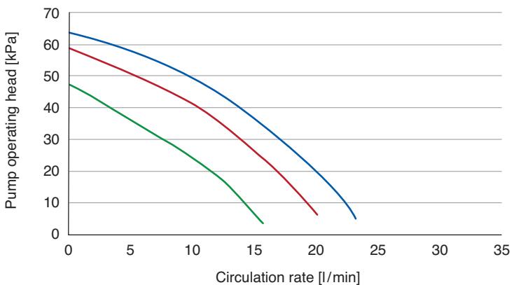
line
| Circulation rate [l/min] | Pump operating head [kPa] (Blue) | Pump operating head [kPa] (Red) | Pump operating head [kPa] (Green) | | ------------------------ | --------------------------------- | -------------------------------- | ---------------------------------- | | 0 | 65 | 60 | 48 | | 15 | 40 | 30 | 15 | | 20 | 20 | 10 | 5 | | 25 | 5 | 0 | 0 |Properties of the standard water circulation pump for the Aquarea heat pumps,
7 (Phase-out model) and 9 kW single phase.
Pump speed 3
Pump speed 2
Pump speed 1
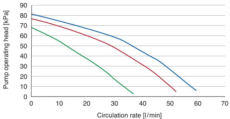
line
| Circulation rate [l/min] | Pump operating head [kPa] (Blue) | Pump operating head [kPa] (Red) | Pump operating head [kPa] (Green) | | ------------------------ | --------------------------------- | -------------------------------- | ---------------------------------- | | 0 | 82 | 78 | 68 | | 10 | 75 | 70 | 55 | | 20 | 68 | 60 | 40 | | 30 | 60 | 50 | 25 | | 40 | 50 | 40 | 10 | | 50 | 35 | 20 | 5 | | 60 | 10 | 5 | 0 |Properties of the standard water circulation pump for the Aquarea heat pumps, 9 kW three phase and 12, 14 and 16 kW single phase and three phase.
Pump delivery head of high-efficiency pumps with differential pressure control
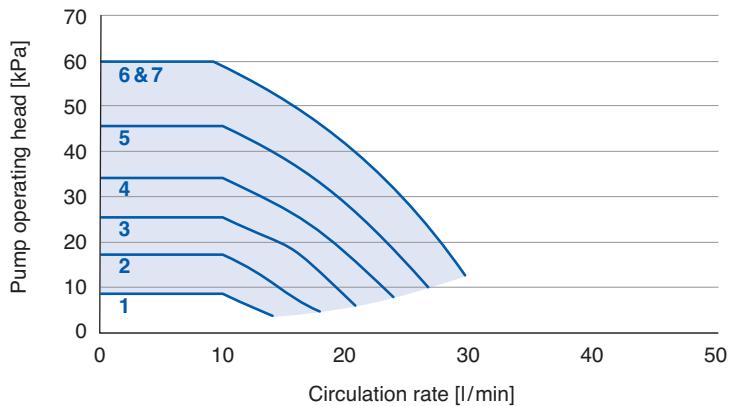
line
| Circulation rate [l/min] | Pump operating head [kPa] | | ------------------------ | ------------------------- | | 0 | 60 | | 10 | 45 | | 20 | 30 | | 30 | 15 |Pump characteristic curve of the high-efficiency water circulation pump with differential pressure control for the Aquarea heat pump units WH-SDF03E3E5, WH-SDF05E3E5, WH-SDC03E3E5 and WH-SDC05E3E5
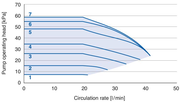
line
| Circulation rate [l/min] | Pump operating head [kPa] | | ------------------------ | ------------------------- | | 0 | 7 | | 20 | 6 | | 40 | 3 | | 60 | 2 | | 80 | 1 |Pump characteristic curve of the high-efficiency water circulation pump with differential pressure control for the Aquarea heat pump units WH-MDF06E3E5, WH-MDF09E3E5, WH-MDC09E3E5, WH-SXF09E3E8 and WH-SXF12D9E8 (Phase-out models)
Pump delivery head of high-efficiency pumps without differential pressure control
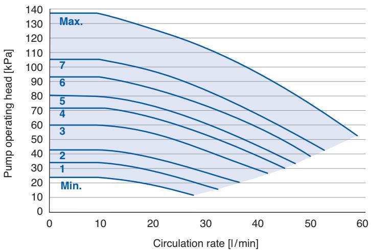
line
| Circulation rate [l/min] | Pump operating head [kPa] | | ------------------------ | ------------------------- | | 0 | 140 | | 10 | 135 | | 20 | 125 | | 30 | 110 | | 40 | 95 | | 50 | 80 | | 60 | 65 |Pump characteristic curve of the high-efficiency water circulation pump without differential pressure control for the Aquarea heat pump units of the F generation or later
5.13.4 Hydraulic balancing
The hydraulic balancing of the heat transfer system is achieved from correct setting of the circulation rates from regulating valves. In this manner, a situation where individual building areas are excessively heated up whereas other sections remain cold with low circulation rates is avoided. The hydraulic balancing is therefore a question of home comfort and at the same time also a prerequisite for efficient operation of air/water heat pump.
5.13.5 Special behaviour when cooling
Hydraulically, a heat pump system with cooling does not differ from a pure heating system. For the calculation of seasonal performance factor, both the heat produced and heat removed via cooling should be measured with a meter.
5.13.6 Expansion vessel
With the exception of the mini Monobloc units with a heating capacity of 5, 6 and 9 kW respectively (see note), the Aquarea heat pumps have an internal expansion vessel with a capacity of 10 litres and an initial pressure of 1 bar.
This expansion vessel can be used for heating systems with an overall quantity of water in the system of under 200 litres and a static head of not more than 7 metres (difference between the highest point of the system to the expansion vessel).
When the overall quantity of water is greater than 200 litres or greater static heads are required, the pressure must be sustained by means of an expansion vessel that is installed in the building itself. In general the pressure limit of the pressure relief valve must be observed. This may be derived from the technical data and is maximum 3 bar.

Note
Unlike the other units, the mini Monobloc units WH-MDC05F3E5, WH-MDF06E3E5 and WH-MDF09E3E5 with a heating capacity of 5, 6 and 9 kW respectively have an expansion vessel with only 6 litres capacity. Accordingly, these units can only be used in heating systems with a total water volume of less than 150 litres. The other conditions correspond to those of the other units.
The required expansion vessel is designed according to the nominal volume VN taking into account:
System volume
V_A (Total volume of the heating system)
Maximum temperature
T_max (Highest temperature in the system, e.g. 60^ )
Final pressure of the pressure relief valve
p_e (Depends on the pressure relief valve, max. 2.5 bar)
Admission pressure expansion vessel
p_0 (Initial pressure 1 bar)
$$ V _ {N} = \left(V _ {e} + V _ {v}\right) \frac {p _ {e} + 1}{p _ {e} - p _ {0}} $$
- The expansion volume Ve is based on the system volume, the maximum temperature and the expansion coefficient of water according to the following table:
| T_max [°C] | 40 | 50 | 60 | 70 | 80 | 90 | 100 |
| n [%] | 0.93 | 1.29 | 1.71 | 2.22 | 2.81 | 3.47 | 4.21 |
Percentage expansion of water
$$ V _ {e} = V _ {A} \frac {n}{1 0 0} $$
- The volume of the water header VV can be calculated by a simplified method:
$$ \begin{array}{l} V _ {V} = 0. 2 \times V _ {N} \quad (\text { with a nominal volume of VN } < 1 5 \text { litres }) \text { or } \ \begin{array}{l l} \mathrm {V_ {v}} = 0. 0 0 5 \times \mathrm {V_ {A}} & (\text { with a nominal volume of VN } > 1 5 \text { litres }, \ & \text { whereby VV } \geq 3 \text { litres }) \end{array} \ \end{array} $$
- The final pressure of the pressure relief valve is derived from the opening pressure of the pressure relief valve minus a tolerance of 0.5 bar:
p_e = opening pressure pressure relief valve minus 0.5 bar
- The admission pressure p_0 must be such that it corresponds to the static head of the heating system and an additional pressure of max. 0.5 bar. A static head of 10 metres corresponds to 1 bar. The admission pressure of the Aquarea expansion vessel may have to be adjusted.

Note
The calculation of the expansion vessel is done according to EN 12828 Heating systems in buildings – Design for water-based heating systems. For dimensioning with local requirements, design programs from manufacturers for expansion vessels can be used generally. These calculate also the required admission pressure values to be set on the expansion vessel.

Attention
Aquarea heat pumps may only be installed as closed systems without direct contact of the heating water to the ambient air. The oxygen transfer in open systems can lead to excessive corrosion of the piping and thus to problems in operation.
5.13.7 Heating water quality
To avoid damage to the heating system and to the heat pump, limestone formation in drinking water heaters and hot water heating systems must be observed. Furthermore, heating systems must be flushed thoroughly prior to filling them.
5.13.8 Use of buffer tanks
Buffer tanks can fulfil three functions in connection with heat pumps:
• Bridging outage time by electrical supply companies,
- hydraulic decoupling of the heat pump circuits from the heat transfer system and
- extension of the heat pump service life by preventing frequent switch on and off (cycling), which reduces the system efficiency.
Owing to the inverter technology of Aquarea heat pumps, the system capacity can be regulated in line with the heat requirement, ensuring efficiency and meaning a buffer tank is not needed, thus saving space. To bridge the outage time by the electrical supply company, heat transfer systems with greater storage capacity like underfloor heating systems can cater for adequate intermediate storage.
6 Examples
On the following pages there are typical user examples of Aquarea heat pump systems with different applications and properties illustrated. An overview of the examples are shown in following table.
| Example | Several heating circuits | Hydraulic decoupling | Hot water tank | Storage | Cooling | Solar Thermal | Cascade | Page |
| 1 | x | - | x | - | - | - | - | 101 |
| 2 | x | - | x | - | x | - | - | 102 |
| 3 | x | - | x | - | x | - | - | 103 |
| 4* | - | x | x | x | - | - | - | 104 |
| 5* | - | x | x | x | - | x | - | 105 |
| 6* | x | x | x | - | x | - | - | 106 |
| 7 | - | - | x | - | x | - | - | 107 |
| 8 | - | - | x | - | x | - | - | 108 |
| 9* | x | x | FWS^1 | x | - | - | - | 109 |
| 10* | x | x | - | x | - | - | x | 110 |
Overview of examples on the following pages with illustration of properties and applications. 3 and 8 show the respective previous schemes (2 and 7) in the cooling mode. ^1 FWS = Fresh water station *Suitable for units with high-efficiency pumps with differential pressure control

Note
The schematic diagrams show the essential components. They serve as help for the planning of actual systems and do not include all the components and safety devices that are needed according to EN 12828.
Relevant standards and guidelines must be observed!
If you will be applying for Renewable Heat Incentive (RHI) financial support, your installation may require metering equipment fitted or be designed to be “meter-ready”. For information and diagrams of where this must be fitted, please see: www.microgenerationcertification.org
6.1 Legend
| 2-way directional valve | |
| 3-way directional valve / 3-way mixer | |
| Drain funnel | |
| Shutoff valve | |
| Expansion vessel | |
| Pressure-reducing valve | |
| Buffer tank for minimum volume | |
| Hydraulic switch |
| Valve cap | |
| Manometer | |
| Pump | |
| Control valve | |
| Pipe deaeration | |
| Non-return valve | |
| Filter | |
| Pressure relief valve |
| Temperature sensor | |
| Thermostatic valve/valve for individual room control | |
| Bypass valve | |
| Hot water thermostatic mixer | |
| Hot water appliances | |
| Return flow | |
| Supply | |
| Control cable |
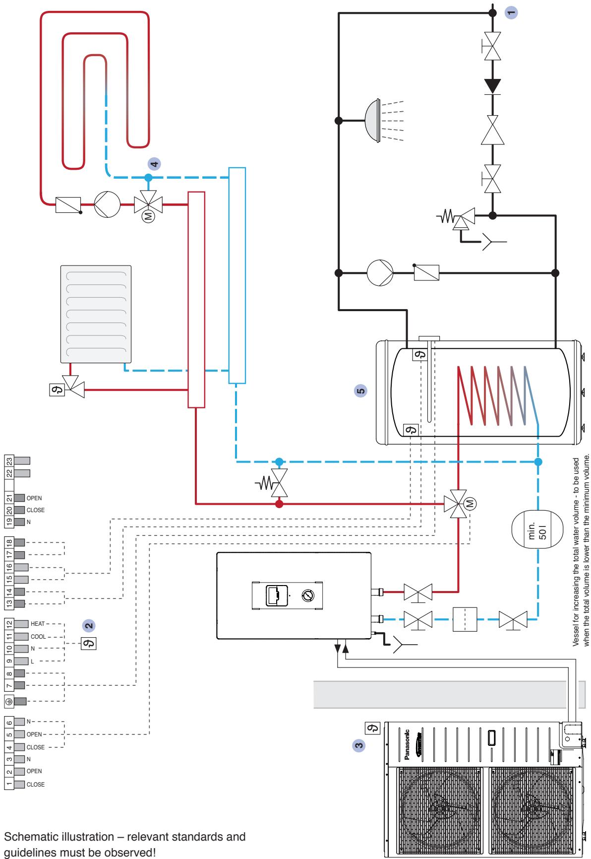
flowchart
graph TD
    A["1 2 3 4 5 6"] --> B["OPEN"]
    B --> C["OPEN"]
    C --> D["OPEN"]
    D --> E["OPEN"]
    E --> F["OPEN"]
    F --> G["OPEN"]
    G --> H["OPEN"]
    H --> I["OPEN"]
    I --> J["OPEN"]
    J --> K["OPEN"]
    K --> L["OPEN"]
    L --> M["OPEN"]
    M --> N["OPEN"]
    N --> O["OPEN"]
    O --> P["OPEN"]
    P --> Q["OPEN"]
    Q --> R["OPEN"]
    R --> S["OPEN"]
    S --> T["OPEN"]
    T --> U["OPEN"]
    U --> V["OPEN"]
    V --> W["OPEN"]
    W --> X["OPEN"]
    X --> Y["OPEN"]
    Y --> Z["OPEN"]
    Z --> AA["OPEN"]
    AA --> AB["OPEN"]
    AB --> AC["OPEN"]
    AC --> AD["OPEN"]
    AD --> AE["OPEN"]
    AE --> AF["OPEN"]
    AF --> AG["OPEN"]
    AG --> AH["OPEN"]
    AH --> AI["OPEN"]
    AI --> AJ["OPEN"]
    AJ --> AK["OPEN"]
    AK --> AL["OPEN"]
    AL --> AM["OPEN"]
    AM --> AN["OPEN"]
    AN --> AO["OPEN"]
    AO --> AP["OPEN"]
    AP --> AQ["OPEN"]
    AQ --> AR["OPEN"]
    AR --> AS["OPEN"]
    AS --> AT["OPEN"]
    AT --> AU["OPEN"]
    AU --> AV["OPEN"]
    AV --> AW["OPEN"]
    AW --> AX["OPEN"]
    AX --> AY["OPEN"]
    AY --> AZ["OPEN"]
    AZ --> BA["OPEN"]
    BA --> BB["OPEN"]
    BB --> BC["OPEN"]
    BC --> BD["OPEN"]
    BD --> BE["OPEN"]
    BE --> BF["OPEN"]
    BF --> BG["OPEN"]
    BG --> BH["OPEN"]
    BH --> BI["OPEN"]
    BI --> BJ["OPEN"]
    BJ --> BK["OPEN"]
    BK --> BL["OPEN"]
    BL --> BM["OPEN"]
    BM --> BN["OPEN"]
    BN --> BO["OPEN"]
    BO --> BP["OPEN"]
    BP --> BQ["OPEN"]
    BQ --> BR["OPEN"]
    BR --> BS["OPEN"]
    BS --> BT["OPEN"]
    BT --> BU["OPEN"]
    BU --> BV["OPEN"]
    BV --> BW["OPEN"]
    BW --> BX["OPEN"]
    BX --> BY["OPEN"]
    BY --> BZ["OPEN"]
    BZ --> CA["OPEN"]
    CA --> CB["OPEN"]
    CB --> CC["OPEN"]
    CC --> CD["OPEN"]
    CD --> CE["OPEN"]
    CE --> CF["OPEN"]
    CF --> CG["OPEN"]
    CG --> CH["OPEN"]
    CH --> CI["OPEN"]
    CI --> CJ["OPEN"]
    CJ --> CK["OPEN"]
    CK --> CL["OPEN"]
    CL --> CM["OPEN"]
    CM --> CN["OPEN"]
    CN --> CO["OPEN"]
    CO --> CP["OPEN"]
    CP --> CQ["OPEN"]
    CQ --> CR["OPEN"]
    CR --> CS["OPEN"]
    CS --> CT["OPEN"]
    CT --> CU["OPEN"]
    CU --> CV["OPEN"]
    CV --> CW["OPEN"]
    CW --> CX["OPEN"]
    CX --> CY["OPEN"]
    CY --> CZ["OPEN"]
Hot water tank
(building side)
Control for heating circuit mixer
(integrated in the outdoor unit)
Outside temperature sensor
Room thermostat
Cold water connection
Schematic illustration – relevant standards and guidelines must be observed!
5
4
3
1
2
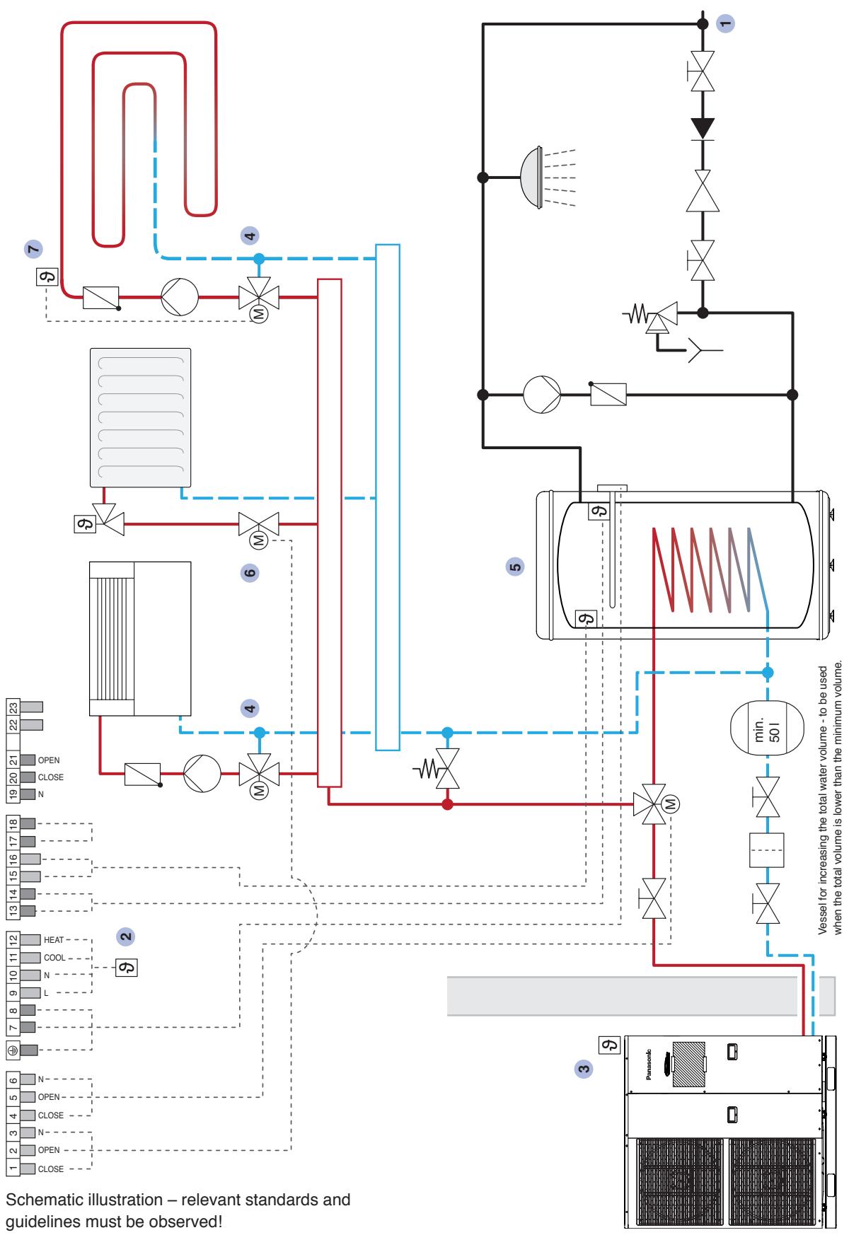
flowchart
graph TD
    A["1 2 3 4 5 6"] --> B["OPEN"]
    B --> C["CLOSE"]
    D["9 2"] --> E["13 14 15 16 17 18"]
    F["9 4"] --> G["M"]
    H["6"] --> I["M"]
    J["4"] --> K["M"]
    L["5"] --> M["9"]
    N["min. 501"] --> O["Panasonic"]
    P["Schematic illustration – relevant standards and guidelines must be observed"] --> Q["19 20 21 22 23"]
    R["Vessel for increasing the total water volume - to be used when the total volume is lower than the minimum volume."] --> S["9"]
    T["Min. 501"] --> U["Panasonic"]
    V["7"] --> W["9"]
    X["4"] --> Y["M"]
    Z["1"] --> AA["Shawn"]
    AB["Open"] --> AC["Open"]
    AD["N"] --> AE["N"]
    AF["L"] --> AG["L"]
    AH["N"] --> AI["N"]
    AJ["COL"] --> AK["COL"]
    AL["HEAT"] --> AM["HEAT"]
1 Cold water connection 3 Outside temperature sensor 4 Control for heating circuit 5 Hot water 6 2-way directional valve 7 Dew point sensor 2 Room thermostat (integrated in the outdoor unit) mixer (building side) tank (open in the heating mode) (building side)
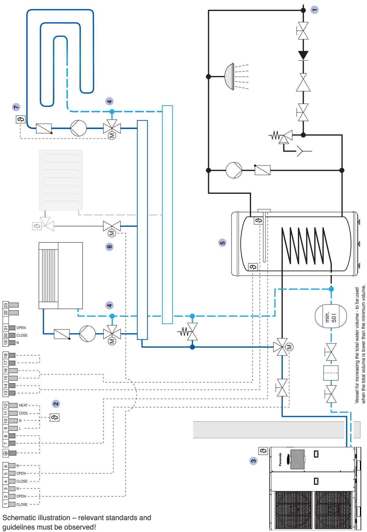
flowchart
graph TD
    A["1 2 3 4 5 6"] --> B["OPEN"]
    B --> C["N"]
    C --> D["OPEN"]
    D --> E["N"]
    E --> F["7 8 9 10 11 12"]
    F --> G["L"]
    G --> H["N"]
    H --> I["COOL"]
    I --> J["HEAT"]
    J --> K["13 14 15 16 17 18"]
    K --> L["OPEN"]
    L --> M["N"]
    M --> N["OPEN"]
    N --> O["HEAT"]
    O --> P["19 20 21 22 23"]
    P --> Q["OPEN"]
    Q --> R["HEAT"]
    R --> S["OPEN"]
    S --> T["HEAT"]
    T --> U["OPEN"]
    U --> V["HEAT"]
    V --> W["OPEN"]
    W --> X["HEAT"]
    X --> Y["OPEN"]
    Y --> Z["HEAT"]
    Z --> AA["OPEN"]
    AA --> AB["HEAT"]
    AB --> AC["OPEN"]
    AC --> AD["HEAT"]
    AD --> AE["OPEN"]
    AE --> AF["HEAT"]
    AF --> AG["OPEN"]
    AG --> AH["HEAT"]
    AH --> AI["OPEN"]
    AI --> AJ["HEAT"]
    AJ --> AK["OPEN"]
    AK --> AL["HEAT"]
    AL --> AM["OPEN"]
    AM --> AN["HEAT"]
    AN --> AO["OPEN"]
    AO --> AP["HEAT"]
    AP --> AQ["OPEN"]
    AQ --> AR["HEAT"]
    AR --> AS["OPEN"]
    AS --> AT["HEAT"]
    AT --> AU["OPEN"]
    AU --> AV["HEAT"]
1 Cold water connection 3 Outside temperature sensor 4 Control for heating cir- 5 Hot water 6 2-way directional valve 7 Dew point sensor 2 Room thermostat (integrated in the outdoor unit) circuit mixer (building side) tank (closed in the cooling mode) (building side)
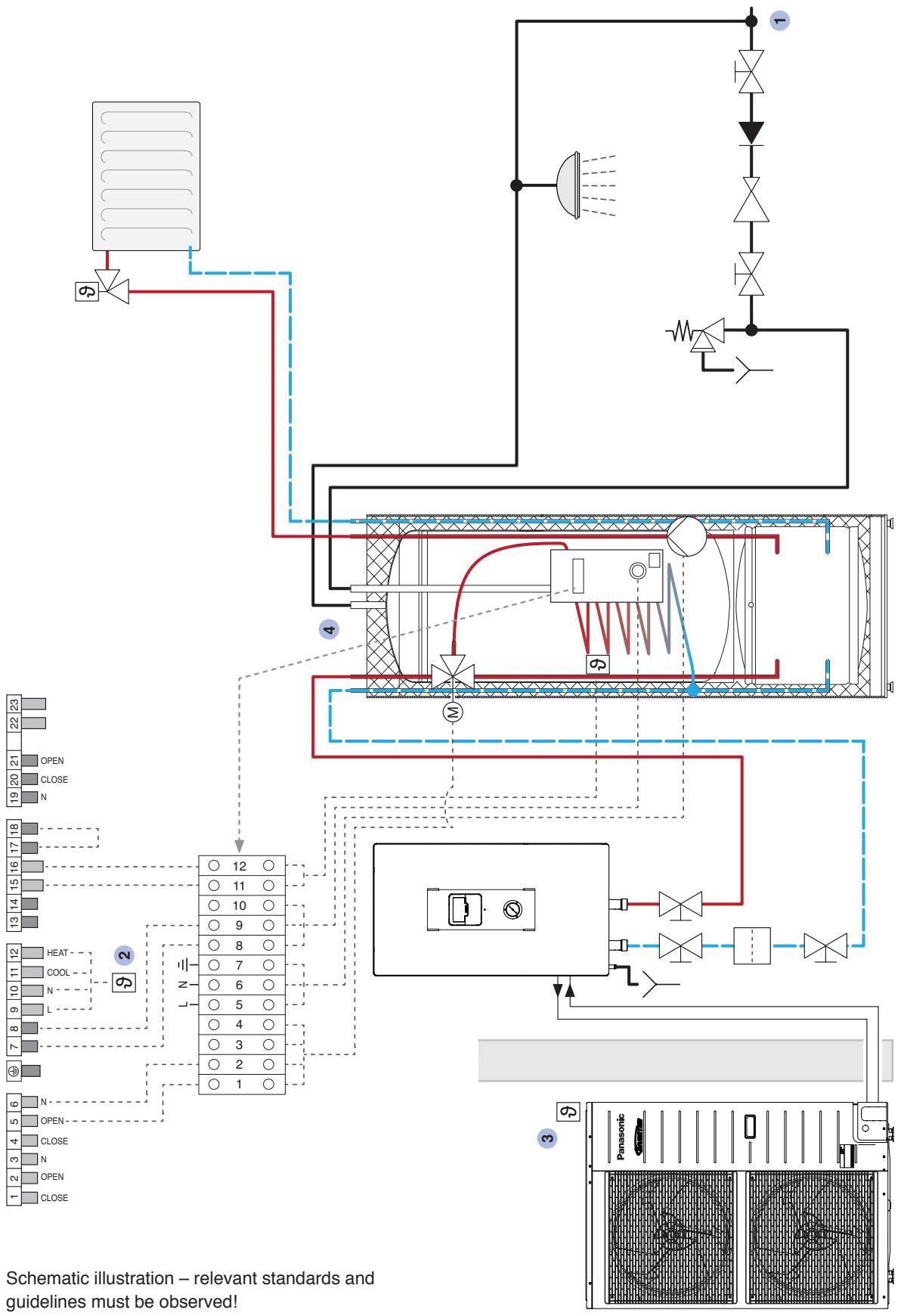
flowchart
graph TD
    A["1 2 3 4 5 6"] --> B["OPEN"]
    B --> C["OPEN-"]
    C --> D["7 8 9 10 11 12"]
    D --> E["HEAT"]
    E --> F["13 14 15 16 17 18"]
    F --> G["OPEN"]
    G --> H["22 23"]
    I["Schematic illustration – relevant standards and guidelines must be observed."] --> J["OPEN"]
    J --> K["L N"]
    K --> L["OPEN"]
    L --> M["OPEN-"]
    M --> N["OPEN-"]
    N --> O["OPEN-"]
    O --> P["OPEN-"]
    P --> Q["OPEN-"]
    Q --> R["OPEN-"]
    R --> S["OPEN-"]
    S --> T["OPEN-"]
    T --> U["OPEN-"]
    U --> V["OPEN-"]
    V --> W["OPEN-"]
    W --> X["OPEN-"]
    X --> Y["OPEN-"]
    Y --> Z["OPEN-"]
    Z --> AA["OPEN-"]
    AA --> AB["OPEN-"]
    AB --> AC["OPEN-"]
    AC --> AD["OPEN-"]
    AD --> AE["OPEN-"]
    AE --> AF["OPEN-"]
    AF --> AG["OPEN-"]
    AG --> AH["OPEN-"]
    AH --> AI["OPEN-"]
    AI --> AJ["OPEN-"]
    AJ --> AK["OPEN-"]
    AK --> AL["OPEN-"]
    AL --> AM["OPEN-"]
    AM --> AN["OPEN-"]
    AN --> AO["OPEN-"]
    AO --> AP["OPEN-"]
    AP --> AQ["OPEN-"]
    AQ --> AR["OPEN-"]
    AR --> AS["OPEN-"]
    AS --> AT["OPEN-"]
    AT --> AU["OPEN-"]
    AU --> AV["OPEN-"]
    AV --> AW["OPEN-"]
    AW --> AX["OPEN-"]
    AX --> AY["OPEN-"]
    AY --> AZ["OPEN-"]
    AZ --> BA["OPEN-"]
    BA --> BB["OPEN-"]
    BB --> BC["OPEN-"]
    BC --> BD["OPEN-"]
    BD --> BE["OPEN-"]
    BE --> BF["OPEN-"]
    BF --> BG["OPEN-"]
    BG --> BH["OPEN-"]
    BH --> BI["OPEN-"]
    BI --> BJ["OPEN-"]
    BJ --> BK["OPEN-"]
    BK --> BL["OPEN-"]
    BL --> BM["OPEN-"]
    BM --> BN["OPEN-"]
    BN --> BO["OPEN-"]
    BO --> BP["OPEN-"]
    BP --> BQ["OPEN-"]
    BQ --> BR["OPEN-"]
    BR --> BS["OPEN-"]
    BS --> BT["OPEN-"]
    BT --> BU["OPEN-"]
    BU --> BV["OPEN-"]
    BV --> BW["OPEN-"]
    BW --> BX["OPEN-"]
    BX --> BY["OPEN-"]
    BY --> BZ["OPEN-"]
    BZ --> CA["OPEN-"]
    CA --> CB["OPEN-"]
    CB --> CC["OPEN-"]
    CC --> CD["OPEN-"]
    CD --> CE["OPEN-"]
4 Aquarea tank
3 Outside temperature sensor (integrated in the outdoor unit)
1 Cold water connection
2 Room thermostat
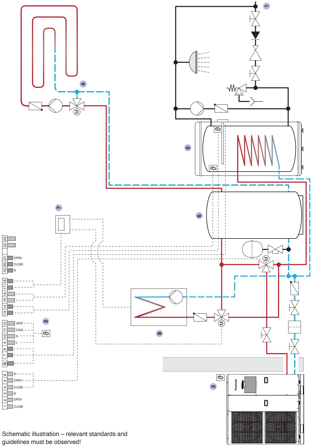
flowchart
graph TD
    A["1 2 3 4 5 6"] --> B["OPEN"]
    B --> C["CLOSE"]
    C --> D["N"]
    D --> E["OPEN"]
    E --> F["CLOSE"]
    F --> G["OPEN"]
    G --> H["N"]
    H --> I["OPEN"]
    I --> J["OPEN"]
    J --> K["OPEN"]
    K --> L["OPEN"]
    L --> M["N"]
    M --> N["OPEN"]
    N --> O["OPEN"]
    O --> P["N"]
    P --> Q["OPEN"]
    Q --> R["OPEN"]
    R --> S["N"]
    S --> T["OPEN"]
    T --> U["OPEN"]
    U --> V["N"]
    V --> W["OPEN"]
    W --> X["OPEN"]
    X --> Y["N"]
    Y --> Z["OPEN"]
    Z --> AA["OPEN"]
    AA --> AB["N"]
    AB --> AC["OPEN"]
    AC --> AD["N"]
    AD --> AE["OPEN"]
    AE --> AF["N"]
    AF --> AG["OPEN"]
    AG --> AH["N"]
    AH --> AI["OPEN"]
    AI --> AJ["N"]
    AJ --> AK["OPEN"]
    AK --> AL["N"]
    AL --> AM["OPEN"]
    AM --> AN["N"]
    AN --> AO["OPEN"]
    AO --> AP["N"]
    AP --> AQ["OPEN"]
    AQ --> AR["N"]
    AR --> AS["OPEN"]
    AS --> AT["N"]
    AT --> AU["OPEN"]
    AU --> AV["N"]
    AV --> AW["OPEN"]
    AW --> AX["N"]
    AX --> AY["OPEN"]
    AY --> AZ["N"]
    AZ --> BA["OPEN"]
    BA --> BB["N"]
    BB --> BC["OPEN"]
    BC --> BD["N"]
    BD --> BE["OPEN"]
    BE --> BF["N"]
    BF --> BG["OPEN"]
    BG --> BH["N"]
    BH --> BI["OPEN"]
    BI --> BJ["N"]
    BJ --> BK["OPEN"]
    BK --> BL["N"]
    BL --> BM["OPEN"]
    BM --> BN["N"]
    BN --> BO["OPEN"]
    BO --> BP["N"]
    BP --> BQ["OPEN"]
    BQ --> BR["N"]
    BR --> BS["OPEN"]
    BS --> BT["N"]
    BT --> BU["OPEN"]
    BU --> BV["N"]
    BV --> BW["OPEN"]
    BW --> BX["N"]
    BX --> BY["OPEN"]
    BY --> BZ["N"]
    BZ --> CA["OPEN"]
    CA --> CB["N"]
    CB --> CC["OPEN"]
    CC --> CD["N"]
    CD --> CE["OPEN"]
    CE --> CF["N"]
    CF --> CG["OPEN"]
    CG --> CH["N"]
    CH --> CI["OPEN"]
    CI --> CJ["N"]
    CJ --> CK["OPEN"]
    CK --> CL["N"]
heat pump and
additional heating
Heating unit with burner
8
6 Buffer tank
7 Higher-level control of
bivalent operation for
4 Control for heating circuit
mixer (building side)
5 Hot water tank
Outside temperature sensor
(integrated in the outdoor unit)
3
Room thermostat
1
2
Schematic illustration – relevant standards and guidelines must be observed!
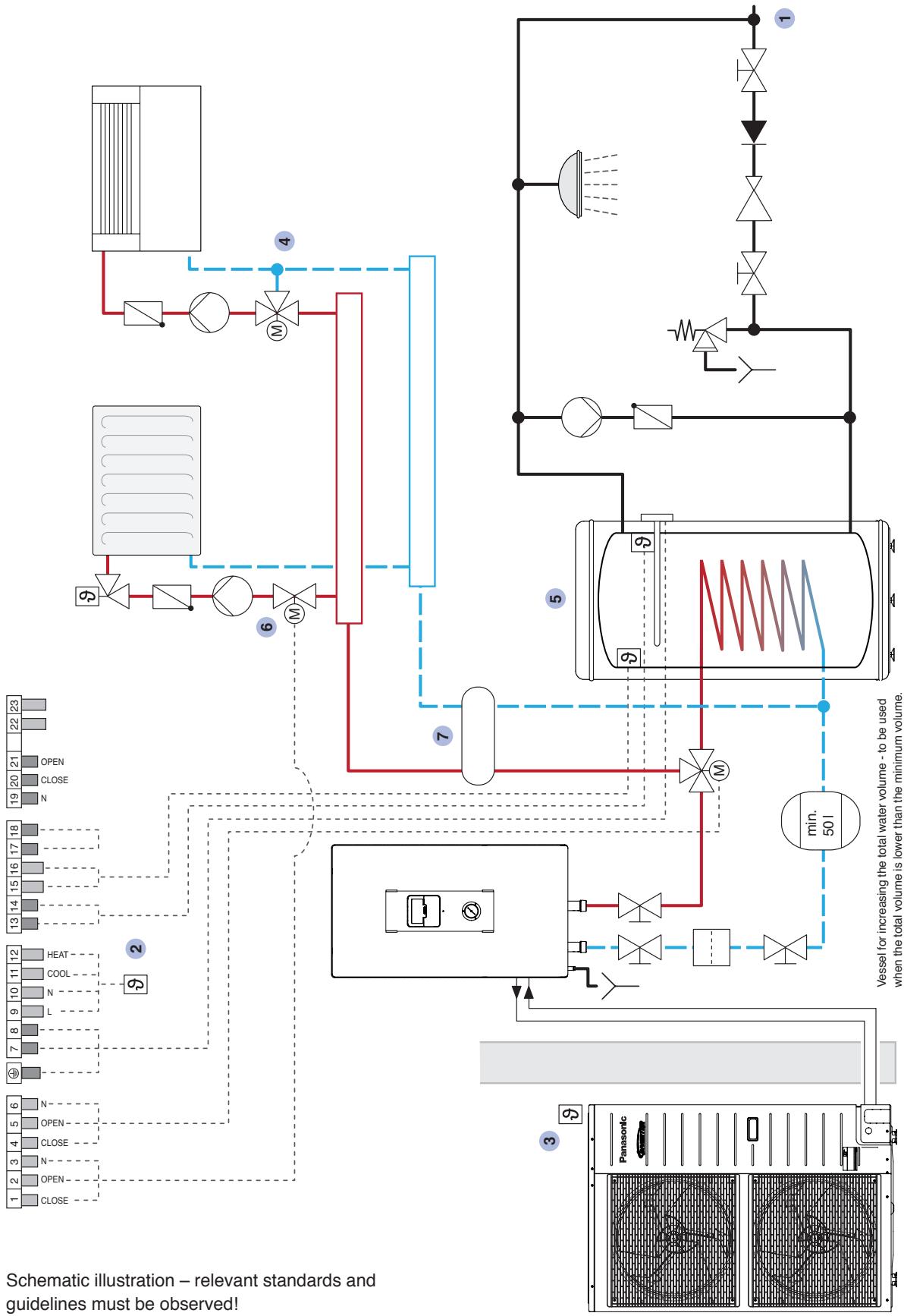
flowchart
graph TD
    A["1 2 3 4 5 6"] --> B["OPEN"]
    B --> C["OPEN"]
    C --> D["N"]
    D --> E["OPEN"]
    E --> F["OPEN"]
    F --> G["N"]
    G --> H["OPEN"]
    H --> I["OPEN"]
    I --> J["N"]
    J --> K["OPEN"]
    K --> L["N"]
    L --> M["OPEN"]
    M --> N["N"]
    N --> O["OPEN"]
    O --> P["N"]
    P --> Q["OPEN"]
    Q --> R["N"]
    R --> S["OPEN"]
    S --> T["N"]
    T --> U["OPEN"]
    U --> V["N"]
    V --> W["OPEN"]
    W --> X["N"]
    X --> Y["OPEN"]
    Y --> Z["N"]
    Z --> AA["OPEN"]
    AA --> AB["N"]
    AB --> AC["OPEN"]
    AC --> AD["N"]
    AD --> AE["OPEN"]
    AE --> AF["N"]
    AF --> AG["OPEN"]
    AG --> AH["N"]
    AH --> AI["OPEN"]
    AI --> AJ["N"]
    AJ --> AK["OPEN"]
    AK --> AL["N"]
    AL --> AM["OPEN"]
    AM --> AN["N"]
    AN --> AO["OPEN"]
    AO --> AP["N"]
    AP --> AQ["OPEN"]
    AQ --> AR["N"]
    AR --> AS["OPEN"]
    AS --> AT["N"]
    AT --> AU["OPEN"]
    AU --> AV["N"]
    AV --> AW["OPEN"]
    AW --> AX["N"]
    AX --> AY["OPEN"]
    AY --> AZ["N"]
7 Heat
exchanger
cooling mode = closed)
2-way directional valve
(heating mode = open,
cooling mode = closed)
6
5 Hot water tank
mixer (building side)
the outdoor unit)
4
Outside temperature
sensor (integrated in
[Non-Text]
3
Cold water connection
2
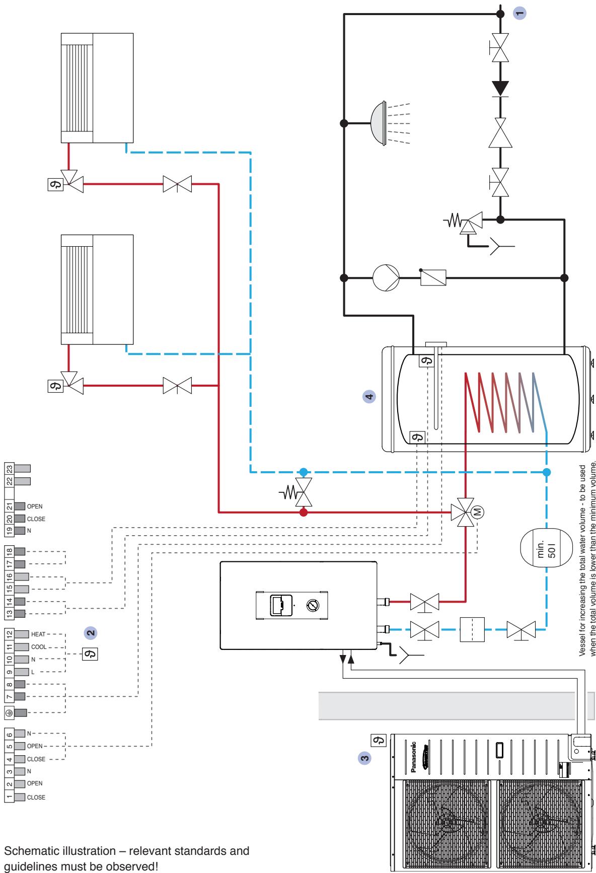
flowchart
graph TD
    A["1 2 3 4 5 6"] --> B["OPEN"]
    B --> C["OPEN"]
    C --> D["OPEN"]
    D --> E["OPEN"]
    E --> F["OPEN"]
    F --> G["OPEN"]
    G --> H["OPEN"]
    H --> I["OPEN"]
    I --> J["OPEN"]
    J --> K["OPEN"]
    K --> L["OPEN"]
    L --> M["OPEN"]
    M --> N["OPEN"]
    N --> O["OPEN"]
    O --> P["OPEN"]
    P --> Q["OPEN"]
    Q --> R["OPEN"]
    R --> S["OPEN"]
    S --> T["OPEN"]
    T --> U["OPEN"]
    U --> V["OPEN"]
    V --> W["OPEN"]
    W --> X["OPEN"]
    X --> Y["OPEN"]
    Y --> Z["OPEN"]
    Z --> AA["OPEN"]
    AA --> AB["OPEN"]
    AB --> AC["OPEN"]
    AC --> AD["OPEN"]
    AD --> AE["OPEN"]
    AE --> AF["OPEN"]
    AF --> AG["OPEN"]
    AG --> AH["OPEN"]
    AH --> AI["OPEN"]
    AI --> AJ["OPEN"]
    AJ --> AK["OPEN"]
    AK --> AL["OPEN"]
    AL --> AM["OPEN"]
    AM --> AN["OPEN"]
    AN --> AO["OPEN"]
    AO --> AP["OPEN"]
    AP --> AQ["OPEN"]
    AQ --> AR["OPEN"]
    AR --> AS["OPEN"]
    AS --> AT["OPEN"]
    AT --> AU["OPEN"]
    AU --> AV["OPEN"]
    AV --> AW["OPEN"]
    AW --> AX["OPEN"]
    AX --> AY["OPEN"]
    AY --> AZ["OPEN"]
    AZ --> BA["OPEN"]
    BA --> BB["OPEN"]
    BB --> BC["OPEN"]
    BC --> BD["OPEN"]
    BD --> BE["OPEN"]
    BE --> BF["OPEN"]
    BF --> BG["OPEN"]
    BG --> BH["OPEN"]
    BH --> BI["OPEN"]
    BI --> BJ["OPEN"]
    BJ --> BK["OPEN"]
    BK --> BL["OPEN"]
    BL --> BM["OPEN"]
    BM --> BN["OPEN"]
    BN --> BO["OPEN"]
    BO --> BP["OPEN"]
    BP --> BQ["OPEN"]
    BQ --> BR["OPEN"]
    BR --> BS["OPEN"]
    BS --> BT["OPEN"]
    BT --> BU["OPEN"]
    BU --> BV["OPEN"]
    BV --> BW["OPEN"]
    BW --> BX["OPEN"]
    BX --> BY["OPEN"]
    BY --> BZ["OPEN"]
    BZ --> CA["OPEN"]
    CA --> CB["OPEN"]
    CB --> CC["OPEN"]
    CC --> CD["OPEN"]
    CD --> CE["OPEN"]
    CE --> CF["OPEN"]
    CF --> CG["OPEN"]
    CG --> CH["OPEN"]
    CH --> CI["OPEN"]
    CI --> CJ["OPEN"]
    CJ --> CK["OPEN"]
    CK --> CR["OPEN"]
    CR --> CS["OPEN"]
    CS --> CT["OPEN"]
    CT --> CU["OPEN"]
    CU --> CV["OPEN"]
    CV --> CW["OPEN"]
    CW --> CX["OPEN"]
    CX --> CY["OPEN"]
    CY --> CZ["OPEN"]
4 Hot water tank
(integrated in the outdoor unit)
Outside temperature sensor
2 Room thermostat
Schematic illustration – relevant standards and guidelines must be observed!
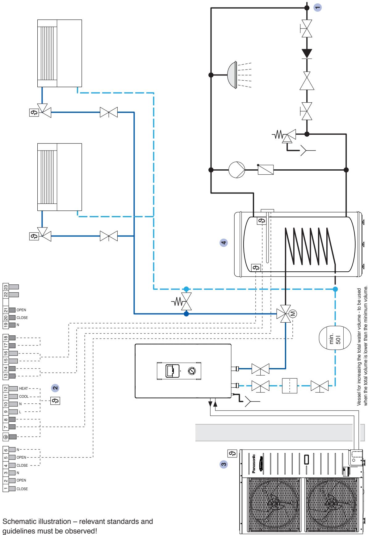
flowchart
graph TD
    A["1 2 3 4 5 6"] --> B["OPEN"]
    B --> C["OPEN"]
    C --> D["OPEN"]
    D --> E["OPEN"]
    E --> F["OPEN"]
    F --> G["OPEN"]
    G --> H["OPEN"]
    H --> I["OPEN"]
    I --> J["OPEN"]
    J --> K["OPEN"]
    K --> L["OPEN"]
    L --> M["OPEN"]
    M --> N["OPEN"]
    N --> O["OPEN"]
    O --> P["OPEN"]
    P --> Q["OPEN"]
    Q --> R["OPEN"]
    R --> S["OPEN"]
    S --> T["OPEN"]
    T --> U["OPEN"]
    U --> V["OPEN"]
    V --> W["OPEN"]
    W --> X["OPEN"]
    X --> Y["OPEN"]
    Y --> Z["OPEN"]
    Z --> AA["OPEN"]
    AA --> AB["OPEN"]
    AB --> AC["OPEN"]
    AC --> AD["OPEN"]
    AD --> AE["OPEN"]
    AE --> AF["OPEN"]
    AF --> AG["OPEN"]
    AG --> AH["OPEN"]
    AH --> AI["OPEN"]
    AI --> AJ["OPEN"]
    AJ --> AK["OPEN"]
    AK --> AL["OPEN"]
    AL --> AM["OPEN"]
    AM --> AN["OPEN"]
    AN --> AO["OPEN"]
    AO --> AP["OPEN"]
    AP --> AQ["OPEN"]
    AQ --> AR["OPEN"]
    AR --> AS["OPEN"]
    AS --> AT["OPEN"]
    AT --> AU["OPEN"]
    AU --> AV["OPEN"]
    AV --> AW["OPEN"]
    AW --> AX["OPEN"]
    AX --> AY["OPEN"]
    AY --> AZ["OPEN"]
    AZ --> BA["OPEN"]
    BA --> BB["OPEN"]
    BB --> BC["OPEN"]
    BC --> BD["OPEN"]
    BD --> BE["OPEN"]
    BE --> BF["OPEN"]
    BF --> BG["OPEN"]
    BG --> BH["OPEN"]
    BH --> BI["OPEN"]
    BI --> BJ["OPEN"]
    BJ --> BK["OPEN"]
    BK --> BL["OPEN"]
    BL --> BM["OPEN"]
    BM --> BN["OPEN"]
    BN --> BO["OPEN"]
    BO --> BP["OPEN"]
    BP --> BQ["OPEN"]
    BQ --> BR["OPEN"]
    BR --> BS["OPEN"]
    BS --> BT["OPEN"]
    BT --> BU["OPEN"]
    BU --> BV["OPEN"]
    BV --> BW["OPEN"]
    BW --> BX["OPEN"]
    BX --> BY["OPEN"]
    BY --> BZ["OPEN"]
    BZ --> CA["OPEN"]
    CA --> CB["OPEN"]
    CB --> CC["OPEN"]
    CC --> CD["OPEN"]
    CD --> CE["OPEN"]
    CE --> CF["OPEN"]
    CF --> CG["OPEN"]
    CG --> CH["OPEN"]
    CH --> CI["OPEN"]
    CI --> CJ["OPEN"]
    CJ --> CK["OPEN"]
    CK --> CR["OPEN"]
    CR --> CS["OPEN"]
    CS --> CT["OPEN"]
    CT --> CU["OPEN"]
    CU --> CV["OPEN"]
    CV --> CW["OPEN"]
    CW --> CX["OPEN"]
    CX --> CY["OPEN"]
    CY --> CZ["OPEN"]
4 Hot water tank
Outside temperature sensor
(integrated in the outdoor unit)
3
2 Room thermostat
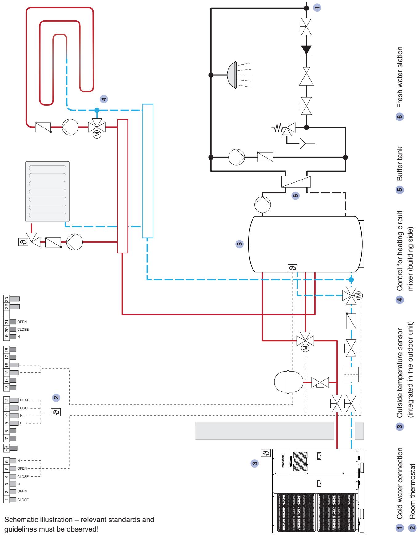
flowchart
graph TD
    A["1 2 3 4 5 6"] --> B["OPEN"]
    B --> C["CLOSE"]
    C --> D["N"]
    D --> E["CLOSE"]
    E --> F["OPEN"]
    F --> G["N"]
    G --> H["OPEN"]
    H --> I["OPEN"]
    I --> J["OPEN"]
    J --> K["OPEN"]
    K --> L["OPEN"]
    L --> M["OPEN"]
    M --> N["OPEN"]
    N --> O["OPEN"]
    O --> P["OPEN"]
    P --> Q["OPEN"]
    Q --> R["OPEN"]
    R --> S["OPEN"]
    S --> T["OPEN"]
    T --> U["OPEN"]
    U --> V["OPEN"]
    V --> W["OPEN"]
    W --> X["OPEN"]
    X --> Y["OPEN"]
    Y --> Z["OPEN"]
    Z --> AA["OPEN"]
    AA --> AB["OPEN"]
    AB --> AC["OPEN"]
    AC --> AD["OPEN"]
    AD --> AE["OPEN"]
    AE --> AF["OPEN"]
    AF --> AG["OPEN"]
    AG --> AH["OPEN"]
    AH --> AI["OPEN"]
    AI --> AJ["OPEN"]
    AJ --> AK["OPEN"]
    AK --> AL["OPEN"]
    AL --> AM["OPEN"]
    AM --> AN["OPEN"]
    AN --> AO["OPEN"]
    AO --> AP["OPEN"]
    AP --> AQ["OPEN"]
    AQ --> AR["OPEN"]
    AR --> AS["OPEN"]
    AS --> AT["OPEN"]
    AT --> AU["OPEN"]
    AU --> AV["OPEN"]
    AV --> AW["OPEN"]
    AW --> AX["OPEN"]
    AX --> AY["OPEN"]
    AY --> AZ["OPEN"]
    AZ --> BA["OPEN"]
    BA --> BB["OPEN"]
    BB --> BC["OPEN"]
    BC --> BD["OPEN"]
    BD --> BE["OPEN"]
    BE --> BF["OPEN"]
    BF --> BG["OPEN"]
    BG --> BH["OPEN"]
    BH --> BI["OPEN"]
    BI --> BJ["OPEN"]
    BJ --> BK["OPEN"]
    BK --> BL["OPEN"]
    BL --> BM["OPEN"]
    BM --> BN["OPEN"]
    BN --> BO["OPEN"]
    BO --> BP["OPEN"]
    BP --> BQ["OPEN"]
    BQ --> BR["OPEN"]
    BR --> BS["OPEN"]
    BS --> BT["OPEN"]
    BT --> BU["OPEN"]
    BU --> BV["OPEN"]
    BV --> BW["OPEN"]
    BW --> BX["OPEN"]
    BX --> BY["OPEN"]
    BY --> BZ["OPEN"]
    BZ --> CA["OPEN"]
    CA --> CB["OPEN"]
    CB --> CC["OPEN"]
    CC --> CD["OPEN"]
    CD --> CE["OPEN"]
    CE --> CF["OPEN"]
    CF --> CG["OPEN"]
    CG --> CH["OPEN"]
    CH --> CI["OPEN"]
    CI --> CJ["OPEN"]
    CJ --> CK["OPEN"]
    CK --> CR["OPEN"]
    CR --> CS["OPEN"]
    CS --> CT["OPEN"]
    CT --> CU["OPEN"]
    CU --> CV["OPEN"]
    CV --> CW["OPEN"]
    CW --> CX["OPEN"]
    CX --> CY["OPEN"]
    CY --> CZ["OPEN"]

Schematic illustration – relevant standards and guidelines must be observed!
Buffer tank
6
Overriding control of the cascade
5
Control for heating circuit mixer (building side)
4
Outside temperature sensor (integrated in the outdoor unit)
3
Room thermostat
2
7 Appendix
Heating capacity in relation to supply water and outside temperature
Aquarea LT – Bi-Bloc system
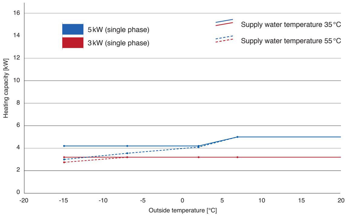
line
| Outside temperature [°C] | 5 kW (single phase) | 3 kW (single phase) | Supply water temperature 35 °C | Supply water temperature 55 °C | | ------------------------ | ------------------- | ------------------- | ------------------------------ | ------------------------------ | | -15 | 4.0 | 3.0 | 2.8 | 2.6 | | -7.5 | 4.0 | 3.0 | 3.0 | 2.8 | | 2.5 | 4.0 | 3.0 | 3.8 | 3.0 | | 7.5 | 5.0 | 3.0 | 4.8 | 3.0 | | 20 | 5.0 | 3.0 | 4.8 | 3.0 |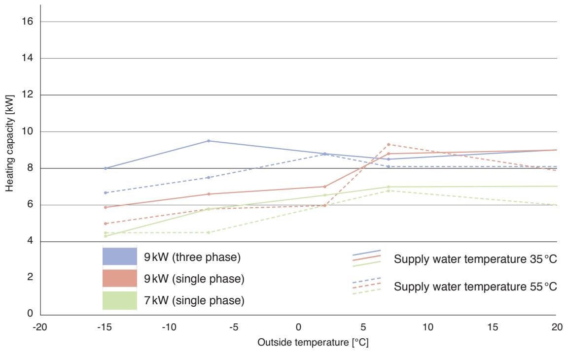
line
| Outside temperature [°C] | 9kW (three phase) | 9kW (single phase) | 7kW (single phase) | Supply water temperature 35 °C | Supply water temperature 55 °C | | ------------------------ | ----------------- | ------------------ | ------------------ | ------------------------------ | ------------------------------ | | -15 | 8.0 | 5.8 | 4.3 | 6.7 | 4.9 | | -7.5 | 9.5 | 6.5 | 5.8 | 7.5 | 5.7 | | 2.5 | 8.8 | 7.0 | 6.0 | 8.8 | 6.0 | | 7.5 | 8.5 | 8.8 | 6.9 | 8.0 | 9.2 | | 20 | 8.8 | 9.0 | 7.0 | 8.0 | 7.8 |Heating capacity [kW] of individual models of the bi-bloc system for different outside temperatures and a supply water temperature of 35 or 55°C.
Aquarea LT – Bi-Bloc system
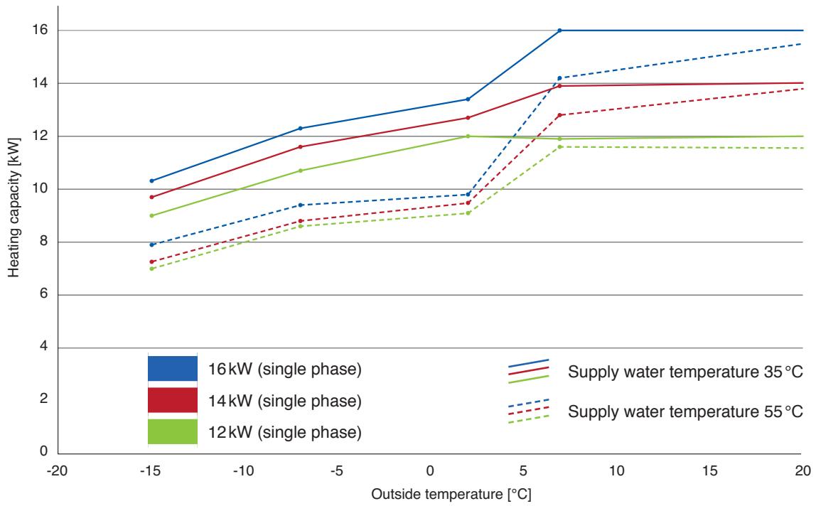
line
| Outside temperature [°C] | 16kW (single phase) | 14kW (single phase) | 12kW (single phase) | Supply water temperature 35 °C | Supply water temperature 55 °C | | ------------------------ | ------------------- | ------------------- | ------------------- | ------------------------------ | ------------------------------ | | -15 | 10.2 | 9.7 | 8.9 | 7.8 | 7.0 | | -7.5 | 12.3 | 11.6 | 10.7 | 9.4 | 8.6 | | 2.5 | 13.3 | 12.7 | 12.0 | 9.8 | 9.0 | | 7.5 | 16.0 | 14.0 | 11.8 | 14.2 | 11.7 | | 20 | 16.0 | 14.0 | 12.0 | 15.5 | 11.7 |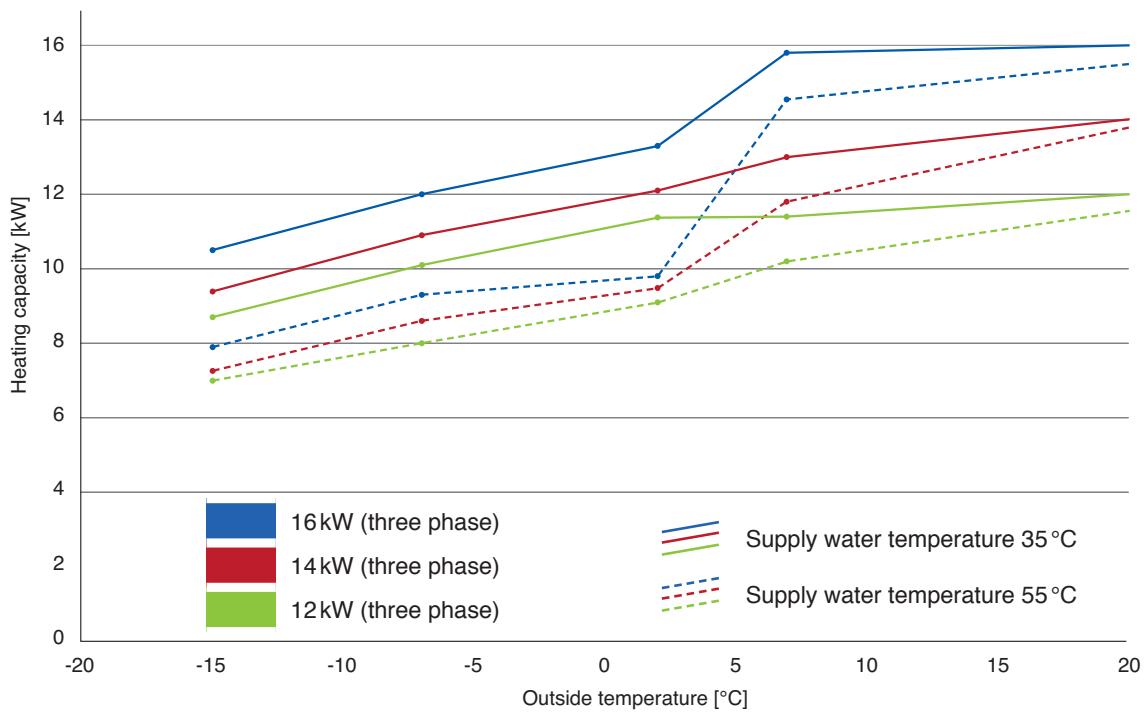
line
| Outside temperature [°C] | 16kW (three phase) | 14kW (three phase) | 12kW (three phase) | Supply water temperature 35 °C | Supply water temperature 55 °C | | ------------------------ | ------------------ | ------------------ | ------------------ | ------------------------------ | ------------------------------ | | -15 | 10.5 | 9.3 | 8.7 | 7.8 | 7.0 | | -5 | 12.0 | 10.8 | 10.0 | 9.2 | 8.0 | | 0 | 13.0 | 12.0 | 11.3 | 9.7 | 9.0 | | 5 | 15.8 | 13.0 | 11.3 | 14.5 | 10.2 | | 20 | 16.0 | 14.0 | 12.0 | 15.5 | 11.5 |Heating capacity [kW] of individual models of the bi-bloc system for different outside temperatures and a supply water temperature of 35 or 55°C.
| Outside temperature | Supply water temperature | Models | |||||
| 30 | 35 | 40 | 45 | 50 | 55 | 3kW (single phase)WH-SDF03E3E5WH-SDC03E3E5 | |
| -15 | 3.2 | 3.2 | 3.1 | 3.0 | 2.8 | 2.75 | |
| -7 | 3.2 | 3.2 | 3.2 | 3.2 | 3.2 | 3.2 | |
| 2 | 3.2 | 3.2 | 3.2 | 3.2 | 3.2 | 3.2 | |
| 7 | 3.2 | 3.2 | 3.2 | 3.2 | 3.2 | 3.2 | |
| 25 | 3.2 | 3.2 | 3.2 | 3.2 | 3.2 | 3.2 | |
| 30 | 35 | 40 | 45 | 50 | 55 | 5kW (single phase)WH-SDF05E3E5WH-SDC05E3E5 | |
| -15 | 4.2 | 4.2 | 3.8 | 3.4 | 3.2 | 3.0 | |
| -7 | 4.2 | 4.2 | 4.0 | 3.8 | 3.7 | 3.55 | |
| 2 | 4.2 | 4.2 | 4.2 | 4.2 | 4.15 | 4.1 | |
| 7 | 5.0 | 5.0 | 5.0 | 5.0 | 5.0 | 5.0 | |
| 25 | 5.0 | 5.0 | 5.0 | 5.0 | 5.0 | 5.0 | |
| 30 | 35 | 40 | 45 | 50 | 55 | 7kW (single phase)WH-SDC07F3E51WH-SDF07C3E5WH-SDC07C3E5(Phase-out models) | |
| -15 | 4.6 | 4.3 | 4.6 | 4.6 | 4.6 | 4.5 | |
| -7 | 5.2 | 5.8 | 5.1 | 5.0 | 4.9 | 4.5 | |
| 2 | 6.7 | 6.6 | 6.6 | 6.7 | 6.3 | 6.0 | |
| 7 | 7.0 | 7.0 | 7.0 | 7.4 | 6.9 | 6.8 | |
| 25 | 7.0 | 7.0 | 6.4 | 6.1 | 5.9 | 5.7 | |
| 30 | 35 | 40 | 45 | 50 | 55 | 9kW (single phase)WH-SDC09F3E51WH-SDF09C3E5WH-SDC09C3E5(Phase-out models) | |
| -15 | 6.0 | 5.9 | 5.5 | 5.4 | 5.2 | 5.0 | |
| -7 | 6.1 | 6.6 | 5.9 | 5.8 | 5.8 | 5.6 | |
| 2 | 6.8 | 7.0 | 6.7 | 6.7 | 6.3 | 6.0 | |
| 7 | 9.0 | 8.8 | 9.0 | 9.0 | 9.0 | 9.3 | |
| 25 | 9.0 | 9.0 | 8.4 | 8.0 | 7.8 | 7.5 | |
| 30 | 35 | 40 | 45 | 50 | 55 | 9kW (three phase)WH-SDC09F3E81WH-SDF09C3E8WH-SDC09C3E8(Phase-out models) | |
| -15 | 8.7 | 8.0 | 8.0 | 7.6 | 7.2 | 6.7 | |
| -7 | 9.4 | 9.5 | 8.9 | 8.7 | 8.3 | 7.5 | |
| 2 | 9.3 | 8.8 | 9.0 | 9.0 | 8.9 | 8.8 | |
| 7 | 9.0 | 8.5 | 9.0 | 8.5 | 9.0 | 8.1 | |
| 25 | 9.0 | 9.0 | 8.7 | 8.5 | 8.3 | 8.1 | |
| 30 | 35 | 40 | 45 | 50 | 55 | 12kW (single phase)WH-SDC12F6E51WH-SDF12C6E5WH-SDC12C6E5(Phase-out models) | |
| -15 | 9.3 | 9.0 | 8.5 | 8.1 | 7.5 | 7.0 | |
| -7 | 10.4 | 10.7 | 9.6 | 9.2 | 8.7 | 8.6 | |
| 2 | 11.8 | 12.0 | 11.0 | 10.9 | 9.8 | 9.1 | |
| 7 | 12.0 | 11.9 | 12.0 | 11.8 | 12.0 | 11.6 | |
| 25 | 12.0 | 12.0 | 11.8 | 11.7 | 11.5 | 11.4 | |
| 30 | 35 | 40 | 45 | 50 | 55 | 14kW (single phase)WH-SDC14F6E51WH-SDF14C6E5WH-SDC14C6E5(Phase-out models) | |
| -15 | 9.9 | 9.7 | 9.0 | 8.6 | 7.9 | 7.3 | |
| -7 | 11.1 | 11.6 | 10.2 | 9.8 | 9.1 | 8.8 | |
| 2 | 12.9 | 12.7 | 11.9 | 11.8 | 10.4 | 9.5 | |
| 7 | 14.0 | 13.9 | 14.0 | 14.2 | 13.6 | 12.8 | |
| 25 | 14.0 | 14.0 | 14.0 | 14.0 | 14.0 | 14.0 | |
| 30 | 35 | 40 | 45 | 50 | 55 | 16kW (single phase)WH-SDC16F6E51WH-SDF16C6E5WH-SDC16C6E5(Phase-out models) | |
| -15 | 10.6 | 10.2 | 10.0 | 9.7 | 8.8 | 7.9 | |
| -7 | 11.9 | 12.3 | 10.8 | 10.3 | 9.6 | 9.4 | |
| 2 | 13.5 | 13.4 | 12.4 | 12.1 | 10.8 | 9.8 | |
| 7 | 16.0 | 16.0 | 16.0 | 15.8 | 15.2 | 14.2 | |
| 25 | 16.0 | 16.0 | 16.0 | 16.0 | 16.0 | 15.9 | |
Heating capacity [kW] of individual models of the bi-bloc system for different supply water and outside temperatures [°C].
^1 Preliminary specifications
| Outside temperature | Supply water temperature | Models | |||||
| 30 | 35 | 40 | 45 | 50 | 55 | 12 kW (three phase)WH-SDC12F9E8 ^1 WH-SDF12C9E8WH-SDC12C9E8(Phase-out models) | |
| -15 | 9.3 | 8.7 | 8.5 | 8.1 | 7.5 | 7.0 | |
| -7 | 10.4 | 10.1 | 9.6 | 9.2 | 8.7 | 8.0 | |
| 2 | 11.8 | 11.4 | 11.0 | 10.6 | 9.8 | 9.1 | |
| 7 | 12.0 | 12.0 | 12.0 | 12.0 | 12.0 | 12.0 | |
| 25 | 12.0 | 12.0 | 11.8 | 11.7 | 11.5 | 11.4 | |
| 30 | 35 | 40 | 45 | 50 | 55 | 14 kW (three phase)WH-SDC14F9E8 ^1 WH-SDF14C9E8WH-SDC14C9E8(Phase-out models) | |
| -15 | 9.9 | 9.4 | 9.0 | 8.6 | 7.9 | 7.3 | |
| -7 | 11.1 | 10.9 | 10.2 | 9.8 | 9.1 | 8.6 | |
| 2 | 12.9 | 12.1 | 11.9 | 11.4 | 10.4 | 9.5 | |
| 7 | 14.0 | 14.0 | 14.0 | 14.0 | 13.6 | 13.3 | |
| 25 | 14.0 | 14.0 | 14.0 | 14.0 | 14.0 | 14.0 | |
| 30 | 35 | 40 | 45 | 50 | 55 | 16 kW (three phase)WH-SDC16F9E8 ^1 WH-SDF16C9E8WH-SDC16C9E8(Phase-out models) | |
| -15 | 10.6 | 10.5 | 10.0 | 9.7 | 8.8 | 7.9 | |
| -7 | 11.9 | 12.0 | 10.8 | 10.3 | 9.6 | 9.3 | |
| 2 | 13.5 | 13.3 | 12.4 | 11.9 | 10.8 | 9.8 | |
| 7 | 16.0 | 15.8 | 16.0 | 15.6 | 15.2 | 14.5 | |
| 25 | 16.0 | 16.0 | 16.0 | 16.0 | 16.0 | 15.9 | |
Heating capacity [kW] of individual models of the Bi-Bloc system for different supply water and outside temperatures [°C].
^1 Preliminary specifications
Aquarea LT – Monobloc system
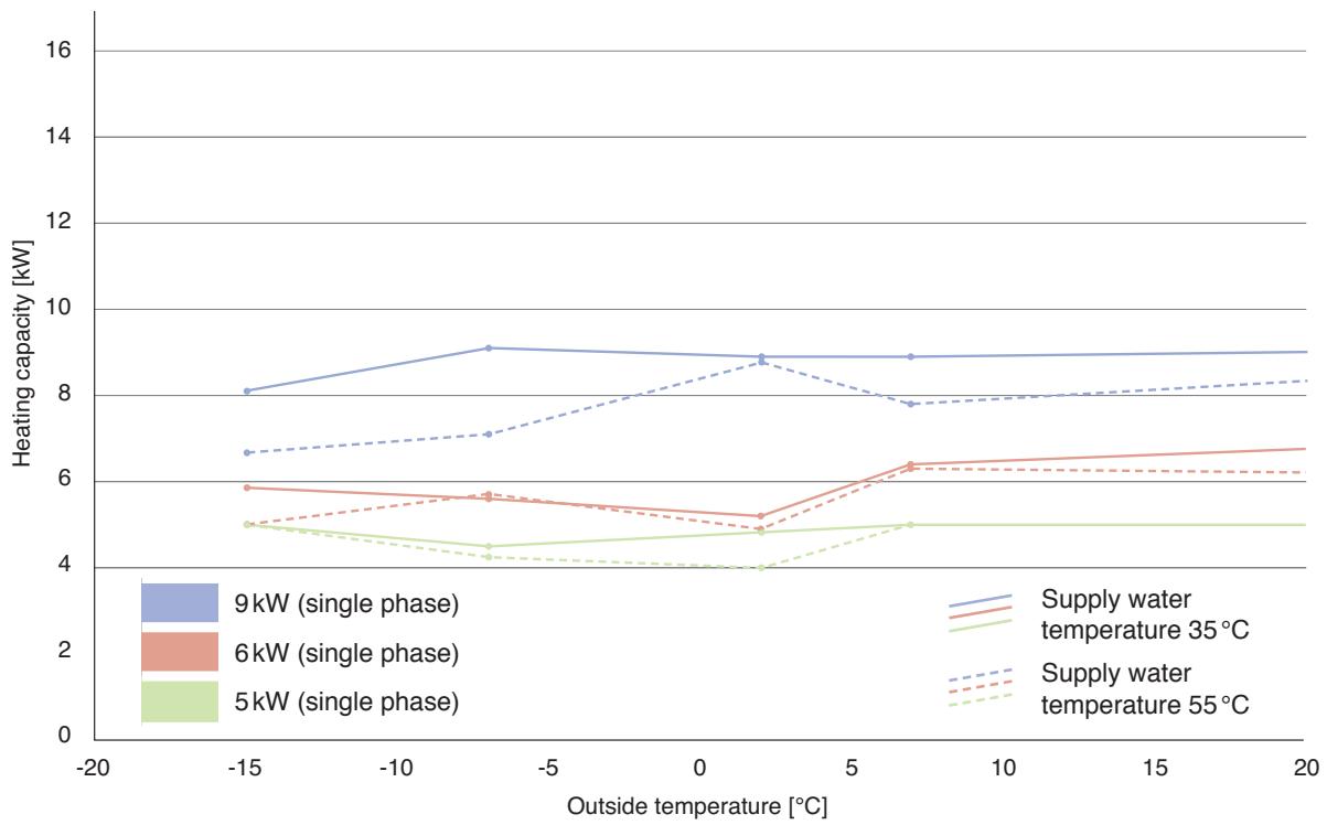
line
| Outside temperature [°C] | 9 kW (single phase) | 6 kW (single phase) | 5 kW (single phase) | | ------------------------ | ------------------- | ------------------- | ------------------- | | -15 | 8.0 | 5.8 | 4.9 | | -7.5 | 9.0 | 5.6 | 4.3 | | 2.5 | 8.8 | 5.1 | 4.8 | | 7.5 | 8.8 | 6.3 | 4.9 | | 20 | 8.8 | 6.6 | 4.9 |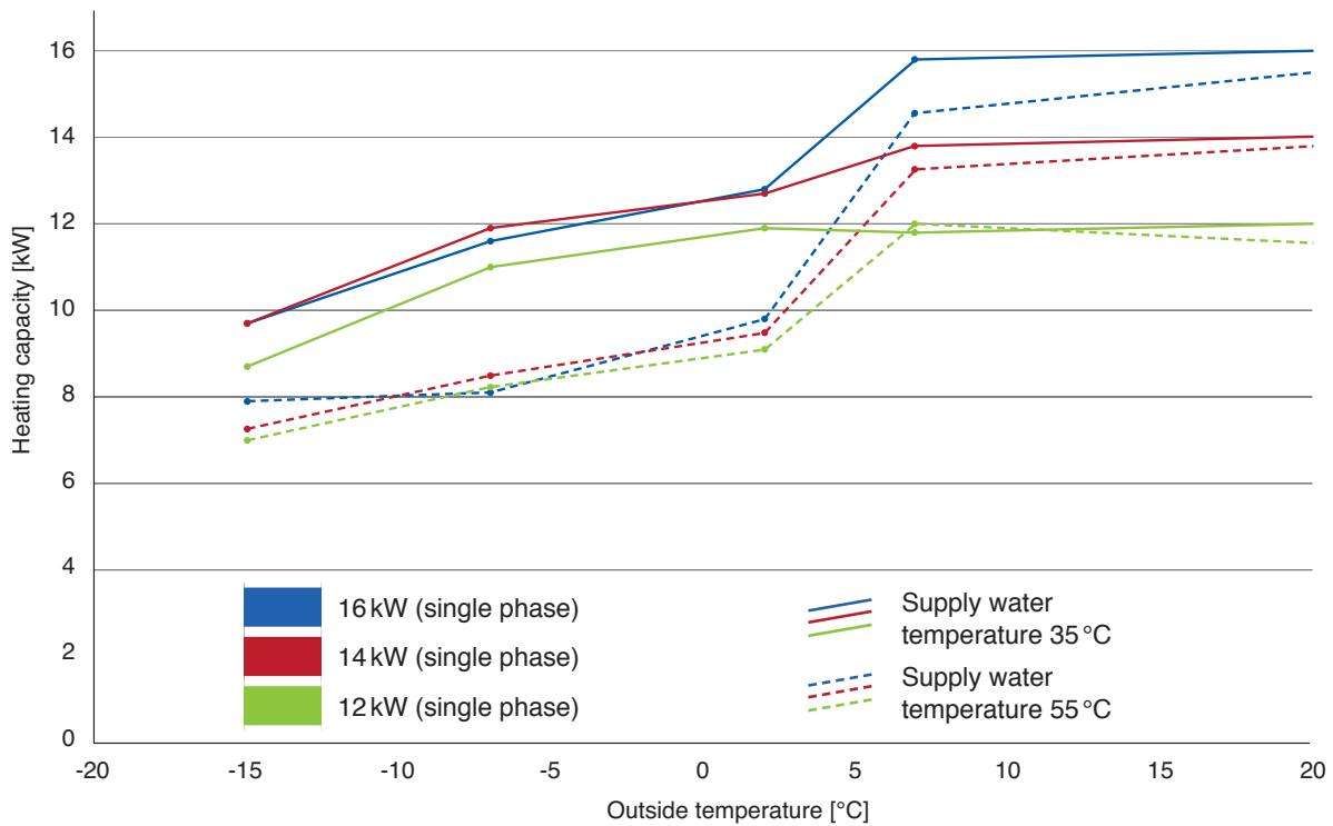
line
| Outside temperature [°C] | 16 kW (single phase) | 14 kW (single phase) | 12 kW (single phase) | | ------------------------ | --------------------- | --------------------- | --------------------- | | -15 | 7.8 | 9.6 | 8.6 | | -7.5 | 11.5 | 11.8 | 10.9 | | 2.5 | 12.7 | 12.7 | 11.8 | | 7.5 | 15.8 | 13.7 | 11.9 | | 20 | 16.0 | 13.9 | 12.0 |Heating capacity [kW] of individual models of the monobloc system for different outside temperatures and a supply water temperature of 35 or 55°C.
Aquarea LT – Monobloc system
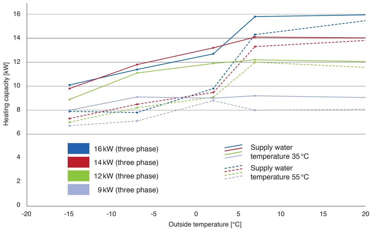
line
| Outside temperature [°C] | 16 kW (three phase) | 14 kW (three phase) | 12 kW (three phase) | 9 kW (three phase) | Supply water temperature 35 °C | Supply water temperature 55 °C | | ------------------------ | ------------------- | ------------------- | ------------------- | ------------------ | ------------------------------ | ------------------------------ | | -15 | 10.0 | 9.8 | 8.8 | 7.9 | 7.8 | 7.2 | | -7.5 | 11.3 | 11.8 | 11.0 | 8.9 | 7.8 | 8.0 | | 2.5 | 12.6 | 13.2 | 11.9 | 8.8 | 9.7 | 9.0 | | 7.5 | 15.8 | 14.0 | 12.0 | 9.0 | 14.2 | 13.2 | | 20 | 15.9 | 14.0 | 12.0 | 8.9 | 15.4 | 13.8 |Heating capacity [kW] of individual models of the monobloc system for different outside temperatures and a supply water temperature of 35 or 55°C.
| Outside temperature | Supply water temperature | Models | |||||
| 30 | 35 | 40 | 45 | 50 | 55 | 5kW (single phase)WH-MDC05F3E5 | |
| -15 | 5.0 | 4.87 | 5.0 | 4.70 | 5.0 | 4.71 | |
| -7 | 4.5 | 5.08 | 4.5 | 4.38 | 4.4 | 4.22 | |
| 2 | 4.8 | 4.75 | 4.7 | 4.80 | 4.3 | 3.40 | |
| 7 | 5.0 | 4.91 | 5.0 | 4.97 | 5.0 | 4.72 | |
| 25 | 5.0 | 5.0 | 5.0 | 5.0 | 5.0 | 5.0 | |
| 30 | 35 | 40 | 45 | 50 | 55 | 6kW (single phase)WH-MDF06E3E5 | |
| -15 | 6.2 | 5.9 | 5.7 | 5.4 | 5.2 | 5.0 | |
| -7 | 5.2 | 5.6 | 5.1 | 5.1 | 5.5 | 5.7 | |
| 2 | 5.0 | 5.2 | 5.0 | 5.3 | 5.0 | 5.0 | |
| 7 | 6.0 | 6.4 | 6.0 | 6.3 | 6.0 | 6.3 | |
| 25 | 7.3 | 7.1 | 6.9 | 6.7 | 6.5 | 6.3 | |
| 30 | 35 | 40 | 45 | 50 | 55 | 9kW (single phase)WH-MDF09E3E5 | |
| -15 | 7.9 | 7.6 | 7.3 | 7.0 | 6.5 | 5.9 | |
| -7 | 7.8 | 7.9 | 7.6 | 7.5 | 7.6 | 7.0 | |
| 2 | 7.0 | 7.5 | 7.0 | 8.0 | 7.0 | 7.0 | |
| 7 | 9.0 | 9.1 | 9.0 | 9.5 | 9.0 | 9.0 | |
| 25 | 9.0 | 9.0 | 9.0 | 9.0 | 9.0 | 9.0 | |
| 30 | 35 | 40 | 45 | 50 | 55 | 9kW (single phase)WH-MDC09E3E5 | |
| -15 | 8.7 | 8.1 | 8.0 | 7.8 | 7.2 | 6.7 | |
| -7 | 9.4 | 9.1 | 8.9 | 8.7 | 8.0 | 7.1 | |
| 2 | 9.3 | 8.9 | 9.0 | 9.0 | 8.3 | 8.8 | |
| 7 | 9.0 | 8.9 | 9.0 | 8.7 | 9.0 | 7.8 | |
| 25 | 9.0 | 9.0 | 8.7 | 8.5 | 8.3 | 8.1 | |
| 30 | 35 | 40 | 45 | 50 | 55 | 12kW (single phase)WH-MDF12C6E5WH-MDC12C6E5 | |
| -15 | 9.3 | 8.7 | 8.5 | 8.1 | 7.5 | 7.0 | |
| -7 | 10.4 | 11.0 | 9.6 | 9.2 | 8.7 | 8.2 | |
| 2 | 11.8 | 11.9 | 11.0 | 10.6 | 9.8 | 9.1 | |
| 7 | 12.0 | 11.8 | 12.0 | 12.0 | 12.0 | 12.0 | |
| 25 | 12.0 | 12.0 | 11.8 | 11.7 | 11.5 | 11.4 | |
| 30 | 35 | 40 | 45 | 50 | 55 | 14kW (single phase)WH-MDF14C6E5WH-MDC14C6E5 | |
| -15 | 9.9 | 9.7 | 9.0 | 8.6 | 7.9 | 7.3 | |
| -7 | 11.1 | 11.9 | 10.2 | 9.8 | 9.1 | 8.5 | |
| 2 | 12.9 | 12.7 | 11.9 | 11.4 | 10.4 | 9.5 | |
| 7 | 14.0 | 13.8 | 14.0 | 14.0 | 13.6 | 13.3 | |
| 25 | 14.0 | 14.0 | 14.0 | 14.0 | 14.0 | 14.0 | |
| 30 | 35 | 40 | 45 | 50 | 55 | 16kW (single phase)WH-MDF16C6E5WH-MDC16C6E5 | |
| -15 | 10.6 | 9.7 | 10.0 | 9.7 | 8.8 | 7.9 | |
| -7 | 11.9 | 11.6 | 10.8 | 10.3 | 9.6 | 8.1 | |
| 2 | 13.5 | 12.8 | 12.4 | 11.9 | 10.8 | 9.8 | |
| 7 | 16.0 | 15.8 | 16.0 | 15.3 | 15.2 | 14.5 | |
| 25 | 16.0 | 16.0 | 16.0 | 16.0 | 16.0 | 15.9 | |
Heating capacity [kW] of individual models of the monobloc system for different supply water and outside temperatures [°C].
| Outside temperature | Supply water temperature | Models | |||||
| 30 | 35 | 40 | 45 | 50 | 55 | 9kW (three phase)WH-MDF09C3E8WH-MDC09C3E8 | |
| -15 | 8.7 | 8.0 | 8.0 | 7.8 | 7.2 | 6.7 | |
| -7 | 9.4 | 9.1 | 8.9 | 8.7 | 8.0 | 7.1 | |
| 2 | 9.3 | 9.0 | 9.0 | 9.0 | 8.3 | 8.8 | |
| 7 | 9.0 | 9.2 | 9.0 | 9.0 | 9.0 | 8.0 | |
| 25 | 9.0 | 9.0 | 8.7 | 8.5 | 8.3 | 8.1 | |
| 30 | 35 | 40 | 45 | 50 | 55 | 12kW (three phase)WH-MDF12C9E8WH-MDC12C9E8 | |
| -15 | 9.3 | 8.9 | 8.5 | 8.1 | 7.5 | 7.0 | |
| -7 | 10.4 | 11.1 | 9.6 | 9.2 | 8.7 | 8.2 | |
| 2 | 11.8 | 11.9 | 11.0 | 10.6 | 9.8 | 9.1 | |
| 7 | 12.0 | 12.2 | 12.0 | 12.0 | 12.0 | 12.0 | |
| 25 | 12.0 | 12.0 | 11.8 | 11.7 | 11.5 | 11.4 | |
| 30 | 35 | 40 | 45 | 50 | 55 | 14kW (three phase)WH-MDF14C9E8WH-MDC14C9E8 | |
| -15 | 9.9 | 9.8 | 9.0 | 8.6 | 7.9 | 7.3 | |
| -7 | 11.1 | 11.8 | 10.2 | 9.8 | 9.1 | 8.5 | |
| 2 | 12.9 | 12.7 | 11.9 | 11.4 | 10.4 | 9.5 | |
| 7 | 14.0 | 14.1 | 14.0 | 14.0 | 13.6 | 13.3 | |
| 25 | 14.0 | 14.0 | 14.0 | 14.0 | 14.0 | 14.0 | |
| 30 | 35 | 40 | 45 | 50 | 55 | 16kW (three phase)WH-MDF16C9E8WH-MDC16C9E8 | |
| -15 | 10.6 | 10.1 | 10.0 | 9.7 | 8.8 | 7.9 | |
| -7 | 11.9 | 11.4 | 10.8 | 10.3 | 9.6 | 7.8 | |
| 2 | 13.5 | 12.7 | 12.4 | 11.9 | 10.8 | 9.8 | |
| 7 | 16.0 | 15.8 | 16.0 | 15.9 | 15.2 | 14.3 | |
| 25 | 16.0 | 16.0 | 16.0 | 16.0 | 16.0 | 15.9 | |
Heating capacity [kW] of individual models of the monobloc system for different supply water and outside temperatures [°C].
Aquarea T-CAP – Bi-Bloc system
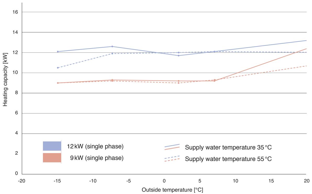
line
| Outside temperature [°C] | 12 kW (single phase) Supply water temperature 35 °C | 12 kW (single phase) 9 kW | 12 kW (single phase) Supply water temperature 55 °C | 9 kW (single phase) Supply water temperature 35 °C | 9 kW (single phase) 9 kW | | ------------------------ | ----------------------------------------------- | ------------------------- | ----------------------------------------------- | ----------------------------------------------- | ------------------------- | | -15 | 12.0 | 10.5 | 10.5 | 8.9 | 8.9 | | -7.5 | 12.6 | 11.8 | 11.8 | 9.2 | 9.2 | | 2.5 | 11.6 | 12.0 | 12.0 | 9.0 | 9.0 | | 7.5 | 12.0 | 12.0 | 12.0 | 9.2 | 9.2 | | 20 | 13.0 | 12.0 | 12.0 | 12.4 | 10.6 |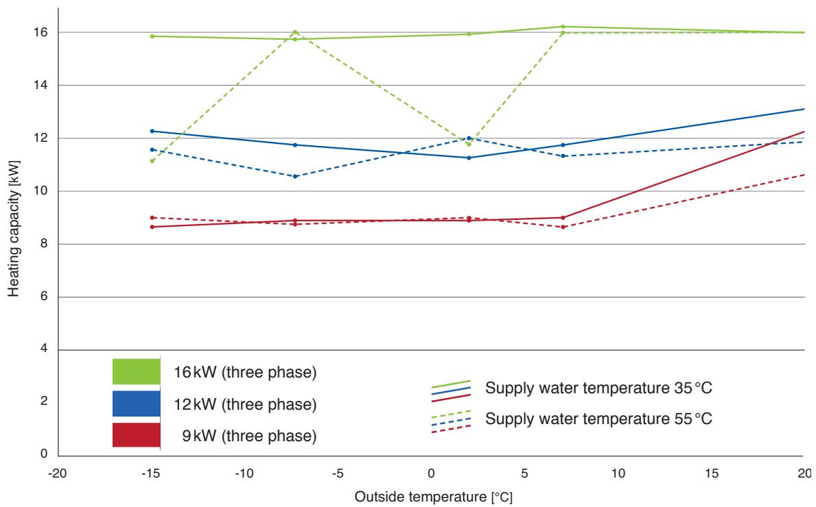
line
| Outside temperature [°C] | 16kW (three phase) | 12kW (three phase) | 9kW (three phase) | Supply water temperature 35°C | Supply water temperature 55°C | | ------------------------ | ------------------ | ------------------ | ----------------- | ----------------------------- | ----------------------------- | | -15 | 15.8 | 12.2 | 8.7 | 11.0 | 8.9 | | -7.5 | 15.8 | 11.7 | 8.8 | 16.0 | 10.5 | | 2.5 | 15.9 | 11.2 | 8.9 | 11.8 | 8.9 | | 7.5 | 16.2 | 11.7 | 8.9 | 16.0 | 8.6 | | 20 | 16.0 | 13.0 | 12.2 | 16.0 | 10.5 |Heating capacity [kW] of individual models of the bi-bloc system for different outside temperatures and a supply water temperature of 35 or 55°C.
| Outside temperature | Supply water temperature | Models | |||||
| 30 | 35 | 40 | 45 | 50 | 55 | 9kW (single phase) WH-SXC09F3E51 WH-SXF09D3E5 WH-SXC09D3E5 (Phase-out models) | |
| -15 | 9.0 | 9.0 | 9.0 | 9.0 | 9.0 | 9.0 | |
| -7 | 9.0 | 9.3 | 9.0 | 9.0 | 9.0 | 9.2 | |
| 2 | 9.0 | 9.2 | 9.0 | 9.2 | 9.0 | 9.0 | |
| 7 | 9.0 | 9.2 | 9.0 | 9.3 | 9.0 | 9.3 | |
| 25 | 13.6 | 13.6 | 13.2 | 12.8 | 12.0 | 11.2 | |
| 30 | 35 | 40 | 45 | 50 | 55 | 12kW (single phase) WH-SXC12F6E51 WH-SXF12D6E5 WH-SXC12D6E5 (Phase-out models) | |
| -15 | 12.0 | 12.1 | 11.5 | 11.0 | 10.7 | 10.5 | |
| -7 | 12.0 | 12.6 | 12.0 | 12.0 | 12.0 | 11.9 | |
| 2 | 12.0 | 11.7 | 12.0 | 12.2 | 12.0 | 12.0 | |
| 7 | 12.0 | 12.1 | 12.0 | 12.3 | 12.0 | 12.1 | |
| 25 | 13.6 | 13.6 | 13.4 | 13.2 | 12.6 | 12.0 | |
| 30 | 35 | 40 | 45 | 50 | 55 | 9kW (three phase) WH-SXC09F3E8 | |
| -15 | 9.0 | 8.69 | 9.0 | 9.0 | 9.0 | 9.0 | |
| -7 | 9.0 | 8.88 | 9.0 | 9.0 | 9.0 | 8.75 | |
| 2 | 9.0 | 8.85 | 9.0 | 9.0 | 9.0 | 9.0 | |
| 7 | 9.0 | 8.96 | 9.0 | 8.68 | 9.0 | 8.66 | |
| 25 | 13.6 | 13.6 | 13.2 | 12.8 | 12.0 | 11.2 | |
| 30 | 35 | 40 | 45 | 50 | 55 | 12kW (three phase) WH-SXC12F9E8 | |
| -15 | 12.0 | 12.23 | 12.0 | 12.0 | 11.8 | 11.6 | |
| -7 | 12.0 | 11.77 | 12.0 | 12.0 | 12.0 | 10.61 | |
| 2 | 12.0 | 11.29 | 12.0 | 12.0 | 12.0 | 12.0 | |
| 7 | 12.0 | 11.74 | 12.0 | 11.81 | 12.0 | 11.35 | |
| 25 | 13.6 | 13.6 | 13.4 | 13.2 | 12.6 | 12.0 | |
| 30 | 35 | 40 | 45 | 50 | 55 | 16kW (three phase) WH-SXC16F9E8 | |
| -15 | 16.0 | 15.89 | 16.0 | 15.70 | 16.0 | 11.11 | |
| -7 | 16.0 | 15.75 | 16.0 | 15.90 | 16.0 | 16.07 | |
| 2 | 16.0 | 15.92 | 16.0 | 15.87 | 16.0 | 11.79 | |
| 7 | 16.0 | 16.28 | 16.0 | 16.27 | 16.0 | 16.0 | |
| 25 | 16.0 | 16.0 | 16.0 | 16.0 | 16.0 | 16.0 | |
Heating capacity [kW] of individual models of the bi-bloc system for different supply water and outside temperatures [°C].
^1 Preliminary specifications
Aquarea T-CAP – Monobloc system
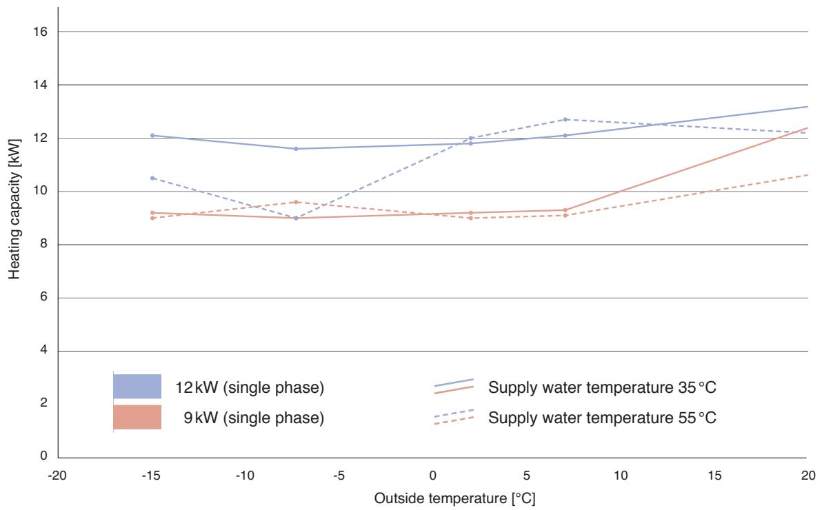
line
| Outside temperature [°C] | 12 kW (single phase) | 9 kW (single phase) | Supply water temperature 35 °C | Supply water temperature 55 °C | | ------------------------ | --------------------- | --------------------- | ------------------------------ | ------------------------------ | | -15 | 12.0 | 9.0 | 10.5 | 9.0 | | -7.5 | 11.5 | 9.0 | 8.8 | 9.5 | | 2.5 | 11.8 | 9.0 | 11.8 | 8.8 | | 7.5 | 12.0 | 9.0 | 12.8 | 9.0 | | 20 | 13.0 | 12.3 | 12.2 | 10.5 |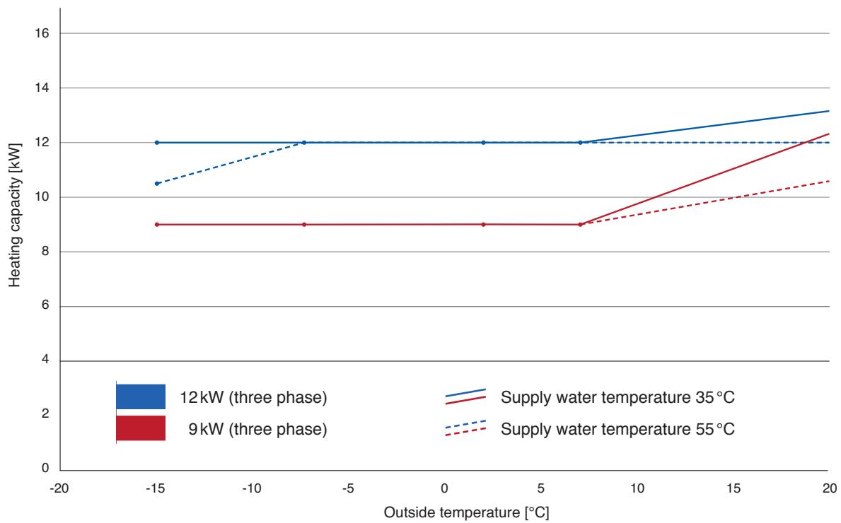
line
| Outside temperature [°C] | 12kW (three phase) | 9kW (three phase) | Supply water temperature 35°C | Supply water temperature 55°C | | ------------------------ | ------------------ | ----------------- | ----------------------------- | ----------------------------- | | -15 | 12 | 9 | 10.5 | 10.5 | | -7.5 | 12 | 9 | 12 | 12 | | 7.5 | 12 | 9 | 12 | 12 | | 20 | 13 | 12 | 12 | 10.5 |Heating capacity [kW] of individual models of the monobloc system for different outside temperatures and a supply water temperature of 35 or 55°C.
| Outside temperature | Supply water temperature | Models | |||||
| 30 | 35 | 40 | 45 | 50 | 55 | 9kW (single phase)WH-MXF09D3E5WH-MXC09D3E5 | |
| -15 | 9.0 | 9.2 | 9.0 | 9.0 | 9.0 | 9.0 | |
| -7 | 9.0 | 9.0 | 9.0 | 9.0 | 9.0 | 9.6 | |
| 2 | 9.0 | 9.2 | 9.0 | 9.0 | 9.0 | 9.0 | |
| 7 | 9.0 | 9.3 | 9.0 | 9.2 | 9.0 | 9.1 | |
| 25 | 13.6 | 13.6 | 13.2 | 12.8 | 12.0 | 11.2 | |
| 30 | 35 | 40 | 45 | 50 | 55 | 12kW (single phase)WH-MXF12D6E5WH-MXC12D6E5 | |
| -15 | 12.0 | 12.1 | 11.5 | 11.0 | 10.7 | 10.5 | |
| -7 | 12.0 | 11.6 | 12.0 | 12.0 | 12.0 | 9.0 | |
| 2 | 12.0 | 11.8 | 12.0 | 12.0 | 12.0 | 12.0 | |
| 7 | 12.0 | 12.1 | 12.0 | 12.5 | 12.0 | 12.7 | |
| 25 | 13.6 | 13.6 | 13.4 | 13.2 | 12.6 | 12.0 | |
| 30 | 35 | 40 | 45 | 50 | 55 | 9kW (three phase)WH-MXF09D3E8WH-MXC09D3E8 | |
| -15 | 9.0 | 9.0 | 9.0 | 9.0 | 9.0 | 9.0 | |
| -7 | 9.0 | 9.0 | 9.0 | 9.0 | 9.0 | 9.0 | |
| 2 | 9.0 | 9.0 | 9.0 | 9.0 | 9.0 | 9.0 | |
| 7 | 9.0 | 9.0 | 9.0 | 9.0 | 9.0 | 9.0 | |
| 25 | 13.6 | 13.6 | 13.2 | 12.8 | 12.0 | 11.2 | |
| 30 | 35 | 40 | 45 | 50 | 55 | 12kW (three phase)WH-MXF12D9E8WH-MXC12D9E8 | |
| -15 | 12.0 | 12.0 | 11.5 | 11.0 | 10.7 | 10.5 | |
| -7 | 12.0 | 12.0 | 12.0 | 12.0 | 12.0 | 12.0 | |
| 2 | 12.0 | 12.0 | 12.0 | 12.0 | 12.0 | 12.0 | |
| 7 | 12.0 | 12.0 | 12.0 | 12.0 | 12.0 | 12.0 | |
| 25 | 13.6 | 13.6 | 13.4 | 13.2 | 12.6 | 12.0 | |
Heating capacity [kW] of individual models of the monobloc system for different supply water and outside temperatures [°C].
Aquarea HT – Bi-Bloc system
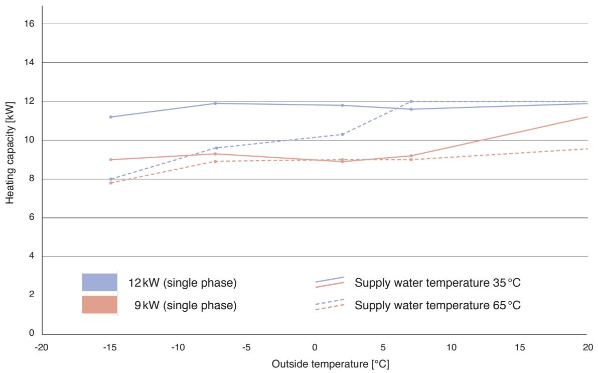
line
| Outside temperature [°C] | 12 kW (single phase) | 9 kW (single phase) | Supply water temperature 35 °C | Supply water temperature 65 °C | | ------------------------ | --------------------- | --------------------- | ------------------------------ | ------------------------------ | | -15 | 11.2 | 8.0 | 7.8 | 7.7 | | -5 | 11.9 | 9.4 | 9.6 | 8.9 | | 0 | 11.8 | 8.9 | 10.2 | 8.9 | | 5 | 11.7 | 8.9 | 11.8 | 8.9 | | 10 | 11.6 | 9.2 | 12.0 | 9.0 | | 15 | 11.8 | 10.2 | 12.0 | 9.3 | | 20 | 11.9 | 11.2 | 12.0 | 9.5 |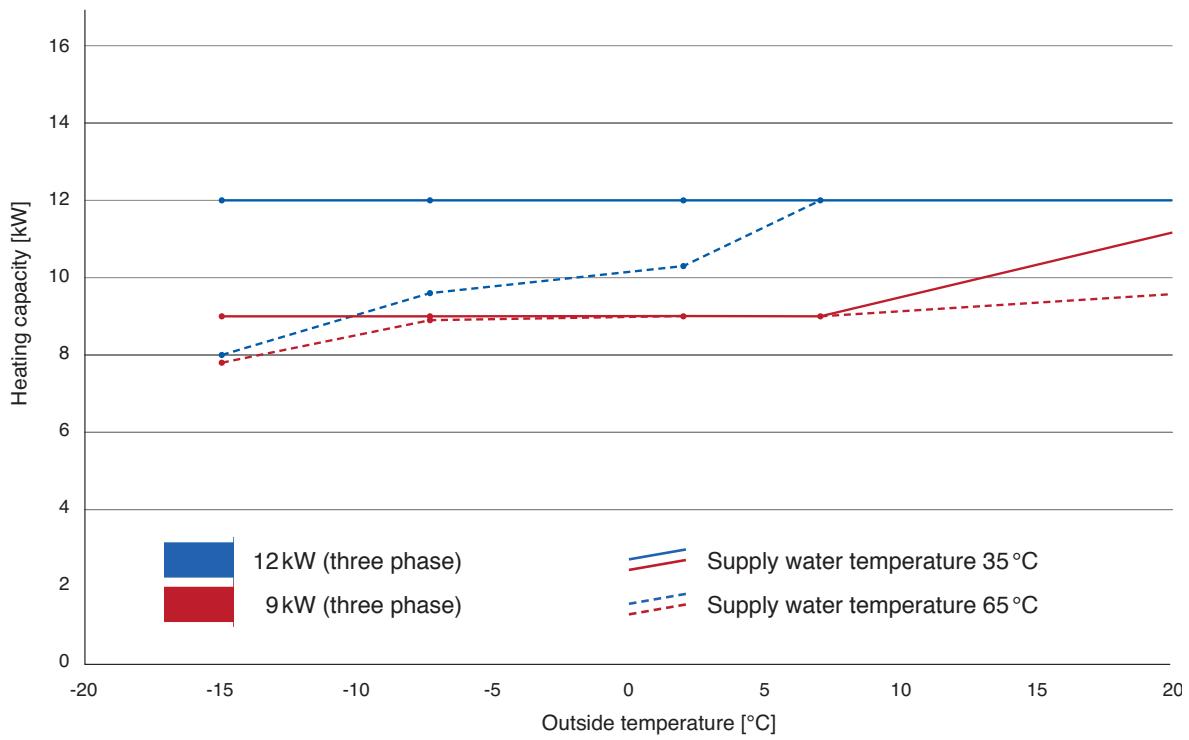
line
| Outside temperature [°C] | 12kW (three phase) | 9kW (three phase) | Supply water temperature 35°C | Supply water temperature 65°C | | ------------------------ | ------------------ | ----------------- | ----------------------------- | ----------------------------- | | -15 | 12 | 8 | 8 | 7.8 | | -7.5 | 12 | 8 | 9.5 | 8.8 | | 2.5 | 12 | 8 | 10.2 | 8.9 | | 7.5 | 12 | 8 | 12 | 9 | | 20 | 12 | 11 | - | - |Heating capacity [kW] of individual models of the bi-bloc system for different outside temperatures and a supply water temperature of 35 or 65°C.
| Outside temperature | Supply water temperature | Models | |||||||
| 30 | 35 | 40 | 45 | 50 | 55 | 60 | 65 | 9kW (single phase) WH-SHF09F3E51 WH-SHF09D3E5 (Phase-out models) | |
| -15 | 9.0 | 9,0 | 8,9 | 8,8 | 8,5 | 8,5 | 8,0 | 7,8 | |
| -7 | 9,0 | 9,3 | 9,0 | 8,9 | 8,9 | 9,3 | 8,9 | 8,9 | |
| 2 | 9,0 | 8,9 | 9,0 | 8,3 | 9,0 | 9,0 | 9,0 | 9,0 | |
| 7 | 9,0 | 9,2 | 9,0 | 9,2 | 9,0 | 8,8 | 9,0 | 9,0 | |
| 25 | 12,0 | 12,0 | 12,0 | 10,8 | 10,2 | 11,2 | 10,0 | 9,8 | |
| 30 | 35 | 40 | 45 | 50 | 55 | 60 | 65 | 12kW (single phase) WH-SHF12F6E51 WH-SHF12D6E5 (Phase-out models) | |
| -15 | 12,0 | 11,2 | 11,0 | 10,6 | 10,3 | 9,7 | 9,0 | 8,0 | |
| -7 | 12,0 | 11,9 | 11,5 | 11,2 | 10,8 | 10,2 | 9,9 | 9,6 | |
| 2 | 12,0 | 11,5 | 11,5 | 10,5 | 11,0 | 10,8 | 10,7 | 10,3 | |
| 7 | 12,0 | 11,6 | 12,0 | 11,5 | 12,0 | 11,7 | 12,0 | 12,0 | |
| 25 | 12,0 | 12,0 | 12,0 | 12,0 | 12,0 | 12,0 | 12,0 | 12,0 | |
| 30 | 35 | 40 | 45 | 50 | 55 | 60 | 65 | 9kW (three phase) WH-SHF09F3E81 WH-SHF09D3E8 (Phase-out models) | |
| -15 | 9,0 | 9,0 | 8,9 | 8,8 | 8,5 | 8,5 | 8,0 | 7,8 | |
| -7 | 9,0 | 9,0 | 9,0 | 8,9 | 8,9 | 8,9 | 8,9 | 8,9 | |
| 2 | 9,0 | 9,0 | 9,0 | 9,0 | 9,0 | 9,0 | 9,0 | 9,0 | |
| 7 | 9,0 | 9,0 | 9,0 | 9,0 | 9,0 | 9,0 | 9,0 | 9,0 | |
| 25 | 12,0 | 12,0 | 12,0 | 10,8 | 10,2 | 11,2 | 10,0 | 9,8 | |
| 30 | 35 | 40 | 45 | 50 | 55 | 60 | 65 | 12kW (three phase) WH-SHF12F9E81 WH-SHF12D9E8 (Phase-out models) | |
| -15 | 12,0 | 12,0 | 11,0 | 10,6 | 10,3 | 9,7 | 9,0 | 8,0 | |
| -7 | 12,0 | 12,0 | 11,5 | 11,2 | 10,8 | 10,1 | 9,9 | 9,6 | |
| 2 | 12,0 | 12,0 | 11,5 | 11,3 | 11,0 | 10,8 | 10,7 | 10,3 | |
| 7 | 12,0 | 12,0 | 12,0 | 12,0 | 12,0 | 12,0 | 12,0 | 12,0 | |
| 25 | 12,0 | 12,0 | 12,0 | 12,0 | 12,0 | 12,0 | 12,0 | 12,0 | |
Heating capacity [kW] of individual models of the bi-bloc system for different supply water and outside temperatures [°C].
^1 Preliminary specifications
Aquarea HT – Monobloc system
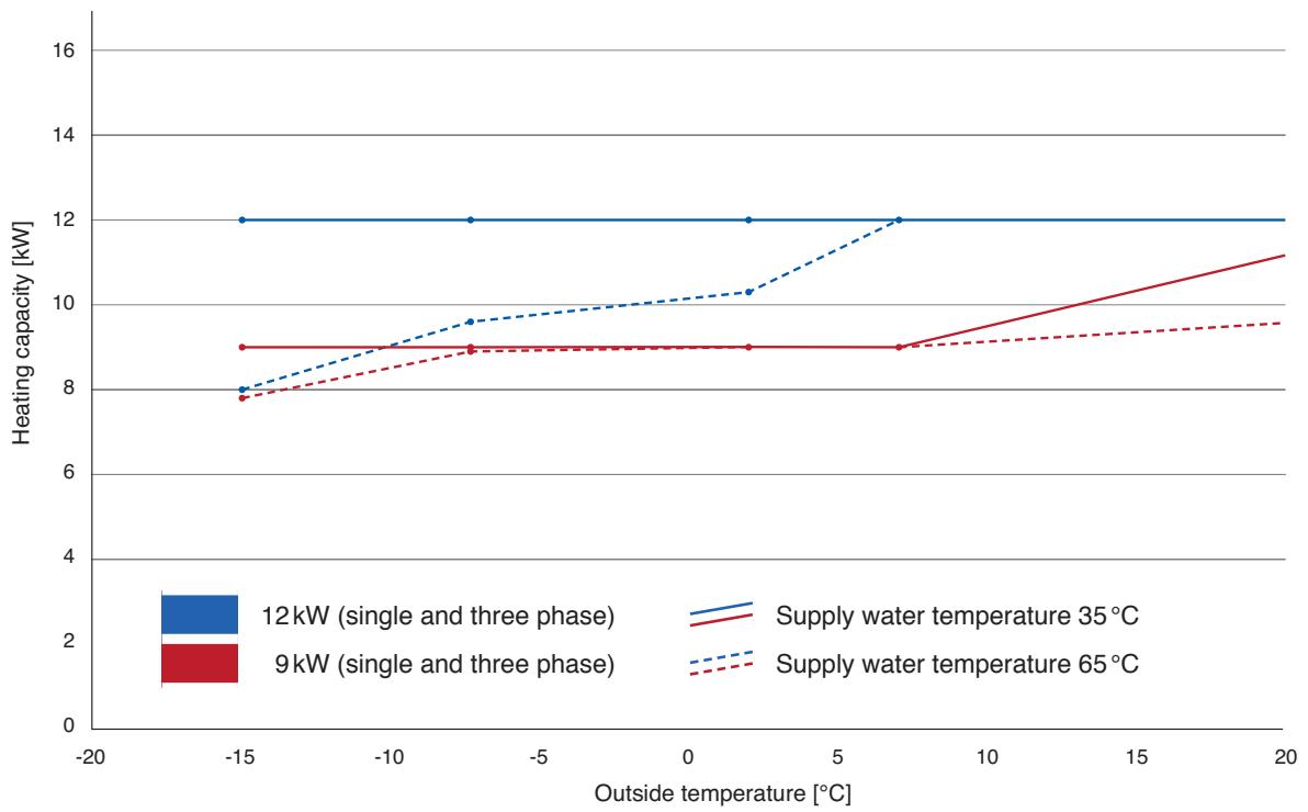
line
| Outside temperature [°C] | 12kW (single and three phase) | 9kW (single and three phase) | Supply water temperature 35°C | Supply water temperature 65°C | | ------------------------ | ----------------------------- | ----------------------------- | ------------------------------ | ------------------------------ | | -15 | 12 | 8 | 8 | 7.8 | | -5 | 12 | 8.8 | 9.5 | 8.8 | | 0 | 12 | 8.8 | 10 | 8.8 | | 5 | 12 | 8.8 | 10.2 | 8.8 | | 10 | 12 | 9 | 12 | 9 | | 15 | 12 | 10 | 12 | 9.2 | | 20 | 12 | 11 | 12 | 9.4 |Heating capacity [kW] of individual models of the monobloc system for different outside temperatures and a supply water temperature of 35 or 65°C.
| Outside temperature | Supply water temperature | Models | |||||||
| 30 | 35 | 40 | 45 | 50 | 55 | 60 | 65 | 9kW (single and three phase)WH-MHF09D3E5WH-MHF09D3E8 | |
| -15 | 9.0 | 9.0 | 8.9 | 8.8 | 8.5 | 8.5 | 8.0 | 7.8 | |
| -7 | 9.0 | 9.0 | 9.0 | 8.9 | 8.9 | 8.9 | 8.9 | 8.9 | |
| 2 | 9.0 | 9.0 | 9.0 | 9.0 | 9.0 | 9.0 | 9.0 | 9.0 | |
| 7 | 9.0 | 9.0 | 9.0 | 9.0 | 9.0 | 9.0 | 9.0 | 9.0 | |
| 25 | 12.0 | 12.0 | 12.0 | 10.8 | 10.2 | 11.2 | 10.0 | 9.8 | |
| 30 | 35 | 40 | 45 | 50 | 55 | 60 | 65 | 12kW (single and three phase)WH-MHF12D6E5WH-MHF12D9E8 | |
| -15 | 12.0 | 12.0 | 11.0 | 10.6 | 10.3 | 9.7 | 9.0 | 8.0 | |
| -7 | 12.0 | 12.0 | 11.5 | 11.2 | 10.8 | 10.1 | 9.9 | 9.6 | |
| 2 | 12.0 | 12.0 | 11.5 | 11.3 | 11.0 | 10.8 | 10.7 | 10.3 | |
| 7 | 12.0 | 12.0 | 12.0 | 12.0 | 12.0 | 12.0 | 12.0 | 12.0 | |
| 25 | 12.0 | 12.0 | 12.0 | 12.0 | 12.0 | 12.0 | 12.0 | 12.0 | |
Heating capacity [kW] of individual models of the monobloc system for different supply water and outside temperatures [°C].
Cooling capacity in relation to supply water and and outside temperature
Aquarea LT
| Outside temperature | Supply water temperature | Models | ||
| 7 | 14 | 18 | 3kW (single phase)WH-SDC03E3E5 | |
| 18 | 2.4 | 4.4 | 3.7 | |
| 25 | 3.2 | 4.1 | 3.5 | |
| 35 | 3.2 | 3.9 | 3.3 | |
| 43 | 2.9 | 3.5 | 3.0 | |
| 7 | 14 | 18 | 5kW (single phase)WH-MDC05F3E5 | |
| 18 | 2.0 | 2.2 | 2.5 | |
| 25 | 5.0 | 6.3 | 6.3 | |
| 35 | 4.5 | 5.1 | 5.0 | |
| 43 | 3.8 | 4.5 | 4.3 | |
| 7 | 14 | 18 | 5kW (single phase)WH-SDC05E3E5 | |
| 18 | 4.5 | 5.0 | 5.7 | |
| 25 | 5.0 | 6.3 | 5.4 | |
| 35 | 4.5 | 5.5 | 5.0 | |
| 43 | 3.3 | 4.1 | 4.4 | |
| 7 | 14 | 18 | 7kW (single phase)WH-SDC07C3E5 | |
| 18 | 5.1 | |||
| 25 | 6.6 | |||
| 35 | 6.0 | 7.3 | 8.0 | |
| 43 | 5.1 | |||
| 7 | 14 | 18 | 9kW (single phase)WH-SDC09C3E5 | |
| 18 | 5.9 | |||
| 25 | 7.8 | |||
| 35 | 7.0 | 8.3 | 9.0 | |
| 43 | 6.2 | |||
| 7 | 14 | 18 | 9kW (single and three phase)WH-MDC09WH-SDC09C6E8 | |
| 18 | 5.9 | |||
| 25 | 7.5 | |||
| 35 | 7.0 | 8.3/8.6 | 9.0/9.5 | |
| 43 | 5.8 | |||
| 7 | 14 | 18 | 12kW (single and three phase)WH-MDC12/WH-SDC12 | |
| 18 | 7.7 | |||
| 25 | 9.2 | |||
| 35 | 10.0 | 11.6/11.8 | 12.5/12.8 | |
| 43 | 7.6 | |||
| 7 | 14 | 18 | 14kW (single and three phase)WH-MDC14/WH-SDC14 | |
| 18 | 8.9 | |||
| 25 | 10.0 | |||
| 35 | 11.5 | 12.8/13.4 | 13.5/14.5 | |
| 43 | 9.1 | |||
| 7 | 14 | 18 | 16kW (single and three phase)WH-MDC16/WH-SDC16 | |
| 18 | 9.6 | |||
| 25 | 10.5 | |||
| 35 | 12.2 | 13.4/14.6 | 14.1/16.0 | |
| 43 | 10.1 | |||
Cooling capacity [kW] of individual models of the split and monobloc systems for different outside temperatures and a supply water temperature of 7^ C.
Aquarea T-CAP
| Outside temperature | Supply water temperature | Models | ||
| 7 | 14 | 18 | 9 kW (single and three phase)WH-MXC09DWH-SXC09D(Phase-out models) | |
| 18 | 7.0 | |||
| 25 | 7.7 | |||
| 35 | 7.0 | 8.3/9.2 | 9.0/10.5 | |
| 43 | 6.3 | |||
| 7 | 14 | 18 | 12 kW (single and three phase)WH-MXC12DWH-SXC12D(Phase-out models) | |
| 18 | 7.5 | |||
| 25 | 8.9 | |||
| 35 | 10.0 | 11.6/12.6 | 12.5/14.0 | |
| 43 | 8.0 | |||
| 7 | 14 | 18 | 9 kW (three phase)WH-SXC09F | |
| 18 | 7.0 | |||
| 25 | 7.7 | |||
| 35 | 7.0 | 11.6 | 12.5 | |
| 43 | 6.3 | |||
| 7 | 14 | 18 | 12 kW (three phase)WH-SXC12F | |
| 18 | 7.5 | |||
| 25 | 8.9 | |||
| 35 | 10.0 | 11.6 | 12.5 | |
| 43 | 8.0 | |||
| 7 | 14 | 18 | 16 kW (three phase)WH-SXC16F | |
| 18 | 8.5 | 10.0 | ||
| 25 | 14.0 | 14.0 | ||
| 35 | 12.2 | 12.2 | ||
| 43 | 7.1 | 9.8 | ||
Cooling capacity [kW] of individual models of the split and monobloc systems for different outside temperatures and a supply water temperature of 7^ C.
Panasonic
To find out how Panasonic cares for you,
log on to: www.aircon.panasonic.co.uk
Contact Details:
Telephone: 01344 853182
www.panasonic-heating.com
Address: Panasonic Air Conditioning
Panasonic House
Willoughby Road
Bracknell
Berkshire
RG12 8FP