USER MANUAL B85-G43 MSI
The material in this document is the intellectual property of MICRO-STAR INTERNATIONAL. We take every care in the preparation of this document, but no guarantee is given as to the correctness of its contents. Our products are under continual improvement and we reserve the right to make changes without notice.
Trademarks
All trademarks in this manual are properties of their respective owners.
MSI® is registered trademark of Micro-Star Int'l Co., Ltd.
NVIDIA® is registered trademark of NVIDIA Corporation.
ATI® is registered trademark of AMD Corporation.
AMD® is registered trademarks of AMD Corporation.
Intel® is registered trademarks of Intel Corporation.
Windows® is registered trademarks of Microsoft Corporation.
AMI® is registered trademark of American Megatrends Inc.
Award® is a registered trademark of Phoenix Technologies Ltd.
Sound Blaster® is registered trademark of Creative Technology Ltd.
Realtek® is registered trademark of Realtek Semiconductor Corporation.
- JMicron® is registered trademark of JMicron Technology Corporation.
Netware® is registered trademark of Novell, Inc.
Lucid® is trademark of LucidLogix Technologies, Ltd.
VIA® is registered trademark of VIA Technologies, Inc.
■ ASMedia® is registered trademark of ASMedia Technology Inc.
- iPad, iPhone, and iPod are trademarks of Apple Inc.
Qualcomm Atheros and Killer are trademarks of Qualcomm Atheros Inc.
Revision History
| Revision | Revision History | Date |
| V1.0 | First release | 2013/ 04 |
Smartphone Application

MSI+ is a smart web gadget that works as a shopping navigator and provides specs comparison for IT buyers. With a simple tap of the smartphone, you'll efficiently locate your ideal products from a wide variety of choices and, if product details are required, you may easily download user manuals within minutes. Better yet, the power calculator provides accurate estimates of power unit capacity for DIY users.


Technical Support
If a problem arises with your system and no solution can be obtained from the user's manual, please contact your place of purchase or local distributor. Alternatively, please try the following help resources for further guidance.

Visit the MSI website for technical guide, BIOS updates, driver updates, and other information: http://www.msi.com/service/download/

Contact our technical staff at: http://support.msi.com
Safety Instructions
Always read the safety instructions carefully.
- Keep this User's Manual for future reference.
- Keep this equipment away from humidity.
- Lay this equipment on a reliable flat surface before setting it up.
- The openings on the enclosure are for air convection hence protects the equipment from overheating. DO NOT COVER THE OPENINGS.
- Make sure the voltage of the power source is at 110/220V before connecting the equipment to the power inlet.
- Place the power cord such a way that people can not step on it. Do not place anything over the power cord.
Always Unplug the Power Cord before inserting any add-on card or module.
All cautions and warnings on the equipment should be noted.
- Never pour any liquid into the opening that can cause damage or cause electrical shock.
If any of the following situations arises, get the equipment checked by service personnel:
The power cord or plug is damaged.
Liquid has penetrated into the equipment.
The equipment has been exposed to moisture.
The equipment does not work well or you can not get it work according to User's Manual.
The equipment has been dropped and damaged.
The equipment has obvious sign of breakage.
- DO NOT LEAVE THIS EQUIPMENT IN AN ENVIRONMENT ABOVE 60^ (140°F), IT MAY DAMAGE THE EQUIPMENT.
FCC-B Radio Frequency Interference Statement
This equipment has been tested and found to comply with the limits for a Class B digital device, pursuant to Part 15 of the FCC Rules. These limits are designed to provide reasonable protection against harmful interference in a residential installation. This equipment generates, uses and can radiate radio frequency energy and, if not installed and used in accordance with the instructions, may cause harmful interference to radio communications. However, there is no guarantee that interference will not occur in a particular installation. If this equipment does cause harmful interference to radio or television reception, which can be determined by turning the equipment off and on, the user is encouraged to try to correct the interference by one or more of the measures listed below.
Reorient or relocate the receiving antenna.
- Increase the separation between the equipment and receiver.
- Connect the equipment into an outlet on a circuit different from that to which the receiver is connected.
Consult the dealer or an experienced radio/television technician for help.
Notice 1
The changes or modifications not expressly approved by the party responsible for compliance could void the user's authority to operate the equipment.
Notice 2
Shielded interface cables and A.C. power cord, if any, must be used in order to comply with the emission limits.
VOIR LA NOTICE D'INSTALLATION AVANT DE RACCORDER AU RESEAU.

Micro-Star International
MS-7816
This device complies with Part 15 of the FCC Rules. Operation is subject to the following two conditions:
1) this device may not cause harmful interference, and
2) this device must accept any interference received, including interference that may cause undesired operation.
Hereby, Micro-Star International CO., LTD declares that this device is in compliance with the essential safety requirements and other relevant provisions set out in the European Directive.


N1996
Radiation Exposure Statement
This equipment complies with FCC radiation exposure limits set forth for an uncontrolled environment. This equipment and its antenna should be installed and operated with minimum distance 20cm between the radiator and your body. This equipment and its antenna must not be co-located or operating in conjunction with any other antenna or transmitter.
The equipment complies with the RF Exposure Requirement 1999/519/EC, Council Recommendation of 12 July 1999 on the limitation of exposure of the general public to electromagnetic fields (0-300GHz). This wireless device complies with the R&TTE Directive.
Taiwan Wireless Statements
無線設備警告聲明
Japan VCCI Class B Statement
クスB情報技術裝置
Korea Warning Statements
当迦末释能尼是运有中正和在

European Union:
Batteries, battery packs, and accumulators should not be disposed of as unsorted household waste. Please use the public collection system to return, recycle, or treat them in compliance with the local regulations.

Taiwan:
For better environmental protection, waste batteries should be collected separately for recycling or special disposal.
廢電池請回收

California, USA:
The button cell battery may contain perchlorate material and requires special handling when recycled or disposed of in California.
For further information please visit:
http://www.dtsc.ca.gov/hazardouswaste/perchlorate/
CAUTION: There is a risk of explosion, if battery is incorrectly replaced.
Replace only with the same or equivalent type recommended by the manufacturer.
In compliance with chemical substances regulations, such as the EU REACH Regulation (Regulation EC No. 1907/2006 of the European Parliament and the Council), MSl provides the information of chemical substances in products at:
http://www.msi.com/html/popup/csr/evmptrtt_pcm.html
ENGLISH
To protect the global environment and as an environmentalist, MSI must remind you that...
Under the European Union ("EU") Directive on Waste Electrical and Electronic Equipment, Directive 2002/96/EC, which takes effect on August 13, 2005, products of "electrical and electronic equipment" cannot be discarded as municipal wastes anymore, and manufacturers of covered
electronic equipment will be obligated to take back such products at the end of their useful life. MSI will comply with the product take back requirements at the end of life of MSI-branded products that are sold into the EU. You can return these products to local collection points.

DEUTSCH
Motherboard Specifications. .En-2
Connectors Quick Guide. En-5
Back Panel Quick Guide. En-7
CPU (Central Processing Unit) .En-9
Memory . En-13
Mounting Screw Holes. En-14
Power Supply. En-15
Expansion Slots. En-16
Video/ Graphics Cards .En-17
Internal Connectors. En-18
Jumper. En-25
Drivers and Utilities. En-26
BIOS Setup .En-27
Deutsch. De-1
Installation/ YcTaHOBka A-1
CPU .A-2
Memory/ Speicher/Mémoire/Памяту .A-4
Motherboard/ Carte mère/ MaTeprHckne nlaTbI .A-5
Power Connector/ATX-Stromanshclus/Connecteurs d'alimentation/Pa3bema nItanra.A-7
SATA HDD. A-9
mSATA SSD .A-10
Front Panel Connector/ Frontpanel Anschluss/ Connecteur panneau avant/ Pa3bemob nepednei panen.. .A-11
Peripheral Connector/ Peripheristecker/ Connecteur périhérique/ Периферийньх pa3bemob. .A-12
Graphics Card/ Grafikkarte/ Carte graphique/ Bundeokapby A-13
English
Thank you for choosing the Z87-G43/ H87-G43/ B85-G43 Series (MS-7816 v1.X) ATX motherboard. The Z87-G43/ H87-G43/ B85-G43 Series motherboards are based on Intel® Z87/ H87/ B85 chipset for optimal system efficiency. Designed to fit the advanced Intel® LGA1150 processor, the Z87-G43/ H87-G43/ B85-G43 Series motherboards deliver a high performance and professional desktop platform solution.
| CPU
Support | ■ 4th Generation Intel® Core™ i7 / Core™ i5 / Core™ i3 / Pentium® / Celeron® processors for LGA 1150 socket |
| Chipset | ■ Intel® Z87 Express Chipset (Z87-G43)■ Intel® H87 Express Chipset (H87-G43)*■ Intel® B85 Express Chipset (B85-G43)** Supports Intel® SBA. |
| Memory
Support | ■ 4x DDR3 memory slots supporting up to 32GB■ Supports DDR3 3000(OC)/ 2800(OC)/ 2666(OC)/ 2600(OC)/ 2400(OC)/ 2200(OC)/ 2133(OC)/ 2000(OC)/ 1866(OC)/ 1600/ 1333/ 1066 MHz- OC is for Z87-G43 only.Dual channel memory architecture■ Supports non-ECC, un-buffered memory■ Supports Intel® Extreme Memory Profile (XMP) |
| Expansion
Slots | ■ 1x PCIe 3.0 x16 slot■ 1x PCIe 2.0 x16 slot- Supports up to PCIe 2.0 x4 speed.■ 2x PCIe 2.0 x1 slots■ 3x PCI slots |
| Onboard
Graphics | ■ 1x VGA port, supporting a maximum resolution of 1920x1200 @ 60Hz■ 1x HDMI® port, supporting a maximum resolution of 4096x2160@24Hz, 24bpp/ 2560x1600@60Hz, 24bpp/ 1920x1080@60Hz, 36bpp■ 1x DVI-D port, supporting a maximum resolution of 1920x1200 @ 60Hz |
| Multi-GPU
Support | ■ Supports 2-Way AMD CrossFire™ Technology*
* Supports Windows 7 and Windows 8. |
| Storage | ■ Intel Z87/ H87/ B85 Express Chipset
- 6x SATA 6Gb/s ports (SATA1~6) (Z87-G43/ H87-G43)
- 4x SATA 6Gb/s ports (SATA1~4) (B85-G43)
- 2x SATA 3Gb/s ports (SATA5~6) (B85-G43)
- Supports RAID 0, RAID1, RAID 5 and RAID 10 (For Z87-G43/H87-G43)
- Supports Intel Smart Response Technology* (Z87-G43 and H87-G43)
- Supports Intel Rapid Start Technology and Intel Smart Connect Technology*
* Supports Intel Core processors on Windows 7 and Windows 8. |
| USB | ■ Intel Z87/ H87/ B85 Express Chipset
- 4x USB 3.0 ports (2 ports on the back panel, 2 ports available through the internal USB connectors)
- 10x USB 2.0 ports (6 ports on the back panel, 4 ports available through the internal USB connectors) |
| Audio | ■ Realtek® ALC892 Codec
- 7.1-Channel High Definition Audio |
| LAN | ■ 1x Realtek® 8111E Gigabit LAN controller |
| Back Panel
Connectors | ■ 1x PS/2 keyboard/ mouse combo port
■ 6x USB 2.0 ports
■ 1x HDMI port
■ 1x VGA port
■ 1x DVI-D port
■ 1x LAN (RJ45) port
■ 2x USB 3.0 ports
■ 6x audio jacks |
| Internal
Connectors | ■ 1x 24-pin ATX main power connector
■ 1x 8-pin ATX 12V power connector
■ 6x SATA 6Gb/s connectors
- For Z87-G43/ H87-G43.
■ 4x SATA 6Gb/s connectors and 2x SATA 3Gb/s connectors
- For B85-G43.
■ 2x USB 2.0 connectors (supports additional 4 USB 2.0 ports)
■ 1x USB 3.0 connectors (supports additional 2 USB 3.0 ports)
■ 2x 4-pin CPU fan connectors
■ 3x 4-pin system fan connectors
■ 1x Clear CMOS jumper
■ 1x Front panel audio connector
■ 2x System panel connectors
■ 1x TPM module connector
■ 1x Serial port connector
■ 1x Parallel port connector
■ 1x Chassis Intrusion connector |
| I/O
Controller | ■ NUVOTON NCT6779 Controller Chip |
| Hardware
Monitor | ■ CPU/System temperature detection
■ CPU/System fan speed detection
■ CPU/System fan speed control |
| BIOS
Features | ■ 64 Mb flash (Z87-G43)
■ 128 Mb flash (H87-G43/ B85-G43)
■ UEFI AMI BIOS
■ ACPI 5.0, PnP 1.0a, SM BIOS 2.7, DMI 2.0
■ Multi-language |
| Special
Features | ■ DigitALL Power
■ Military Class 4
■ OC Genie 4
■ CLICK BIOS 4
■ All Solid CAPs
■ AMD CrossFire
■ PCI Express Gen 3
■ Sound Blaster Cinema (optional)
■ Super RAID
■ USB 3.0
■ SATA 6Gb/s
■ HDMI
■ Command Center
■ Live Update
■ M-Flash |
| Software | ■ Drivers
■ MSI
- Command Center
- Super Charger
- Super RAID
- Live Update 5
- Fast Boot
■ 7-ZIP
■ Intel Turbo Boost Monitor
■ Intel Extreme Tuning Utility
■ Intel Small Business Advantage (Optional)
■ Sound Blaster Cinema (Optional)
■ Norton Internet Security Solution
■ Trend Micro SafeSync |
| Form Factor | ■ ATX Form Factor
■ 12.0 in. x 9.6 in. (30.5 cm x 24.4 cm) |

For the latest information about CPU, please visit http://www.msi.com/service/cpu-support/

For more information on compatible components, please visit http://www.msi.com/service/test-report/
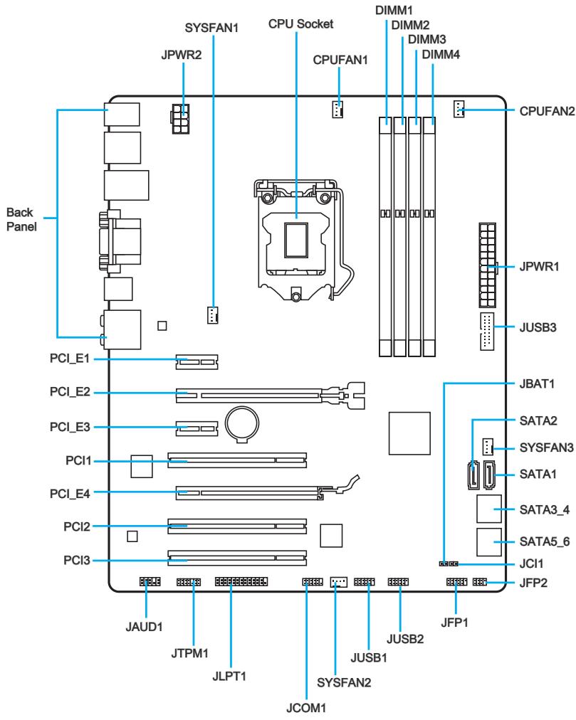
Connectors Reference Guide
| Port Name | Port Type | Page |
| Back Panel | I/O Ports | En-7 |
| CPU Socket | LGA1150 CPU Socket | En-10 |
| CPUFAN1~2,SYSFAN1~3: Fan Power Connectors | En-19 |
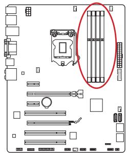
| DIMM1~4 | DDR3 Memory Slots | En-13 |
| JAUD1 | Front Panel Audio Connector | En-23 |
| JBAT1 | Clear CMOS Jumper | En-25 |
| JCI1 | Chassis Intrusion Connector | En-22 |
| JCOM1 | Serial Port Connector | En-24 |
| JFP1, JFP2 | System Panel Connectors | En-20 |
| JLPT1 | Parallel Port Connector | En-23 |
| JPWR1~2 | ATX Power Connectors | En-15 |
| JTPM1 | TPM Module Connector | En-22 |
| JUSB1~2 | USB 2.0 Expansion Connectors | En-21 |
| JUSB3 | USB 3.0 Expansion Connector | En-21 |
| PCI_E1, 3 | PCIe x1 Expansion Slots | En-16 |
| PCI_E2, 4 | PCIe x16 Expansion Slots | En-16 |
| PCI1~3 | PCI Expansion Slots | En-16 |
| SATA1~6 | SATA Connectors | En-18 |
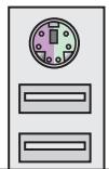
PS/2 Keyboard/
Mouse Combo
Port
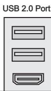
USB 2.0 Port
HDMI
USB 2.0 Port
DVI-D Port

USB 3.0 Port
Mic
SS-Out
PS/2 Keyboard/Mouse Combo Port
A combination of PS/2® mousekeyboard DIN connector for a PS/2® mousekeyboard.
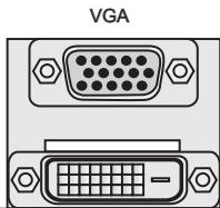
VGA Port
The DB15-pin female connector is provided for monitor.
DVI-D Port
The DVI-D (Digital Visual Interface- Digital) connector can be connected to a LCD monitor, or a CRT monitor with an adapter. To connect a monitor, please refer to the monitor's manual for more information.
HDMI

HIGH-DEFINITION MULTIMEDIA INTERFACE
The High-Definition Multimedia Interface (HDMI) is an all-digital audio-video interface that is capable of transmitting uncompressed streams. HDMI supports all types of TV formats, including standard, enhanced, or high-definition video, plus multi-channel digital audio on a single cable.

Important
This platform supports dual-display or triple-display function by integrated graphics output ports.
| VGA+DVI-D | DVI-D+HDMI | HDMI+VGA | HDMI+VGA+DVI-D |
| Extend mode
(Extend the desktop to the other monitors) | ○ | ○ | ○ | ○ |
| Clone mode
(Monitors have the same screen) | ○ | ○ | ○ | ○ |
USB 2.0 Port
The USB 2.0 port is for attaching USB 2.0 devices such as keyboard, mouse, or other USB 2.0-compatible devices.
USB 3.0 Port
USB 3.0 port is backward-compatible with USB 2.0 devices. It supports data transfer rate up to 5 Gbit/s (SuperSpeed).

Important
In order to use USB 3.0 devices, you must connect to a USB 3.0 port. If a USB cable is used, it must be USB 3.0 compliant.
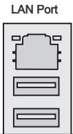
LAN Port
The standard RJ-45 LAN jack is for connecting to a Local Area Network (LAN).
| LINK/ACT
LED SPEED
LED | LED | LED Status | Description |
| Link/ Activity LED | Off | No link |
| Yellow | Linked |
| Blinking | Data activity |
| Speed LED | Off | 10 Mbps connection |
| Green | 100 Mbps connection |
| Orange | 1 Gbps connection |
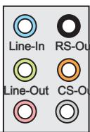
Audio Ports
These connectors are used for audio devices. The color of the jack refers to the function of the connector.
Blue-Line in: Used for connecting external audio outputting devices.
- Green- Line out: Used as a connector for speakers or headphone.
Pink-Mic: Used as a connector for a microphone.
- Black- RS-Out: Rear surround sound line out in 4/ 5.1/ 7.1 channel mode.
Orange-CS-Out: Center/subwoofer line out in 5.1/7.1 channel mode.
Gray-SS-Out: Side surround sound line out in 7.1 channel mode.
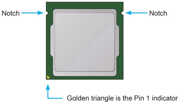
Introduction to the LGA 1150 CPU
The surface of the LGA 1150 CPU has two notches and a golden triangle to assist in correctly lining up the CPU for motherboard placement. The golden triangle is the Pin 1 indicator.

Important
Overheating
Overheating can seriously damage the CPU and motherboard. Always make sure the cooling fans work properly to protect the CPU from overheating. Be sure to apply an even layer of thermal paste (or thermal tape) between the CPU and the heatsink to enhance heat dissipation.
Replacing the CPU
When replacing the CPU, always turn off the system's power supply and unplug the power supply's power cord to ensure the safety of the CPU.
Overclocking
This motherboard is designed to support overclocking. Before attempting to overclock, please make sure that all other system components can tolerate overclocking. Any attempt to operate beyond product specifications is not recommend. MSI does not guarantee the damages or risks caused by inadequate operation beyond product specifications.
CPU & Heatsink Installation
When installing a CPU, always remember to install a CPU heatsink. A CPU heatsink is necessary to prevent overheating and maintain system stability. Follow the steps below to ensure correct CPU and heatsink installation. Wrong installation can damage both the CPU and the motherboard.

Video Demonstration
Watch the video to learn how to install CPU & heatsink. at the address below.
http://youtu.be/bf5La099url

- Push the load lever down to unclip it and lift to the fully open position.
- The load plate will automatically lift up as the load lever is pushed to the fully open position.
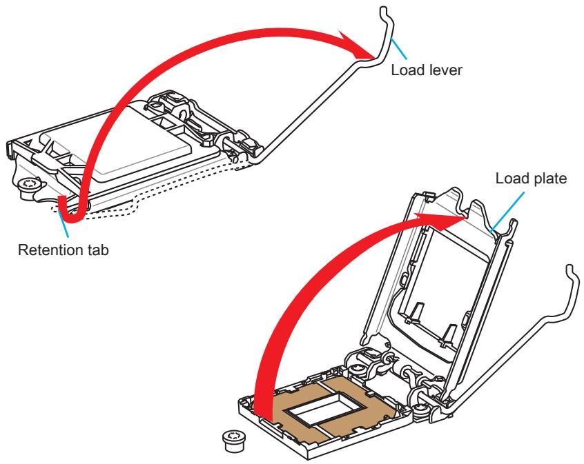

Important
Do not touch the socket contacts or the bottom of the CPU.
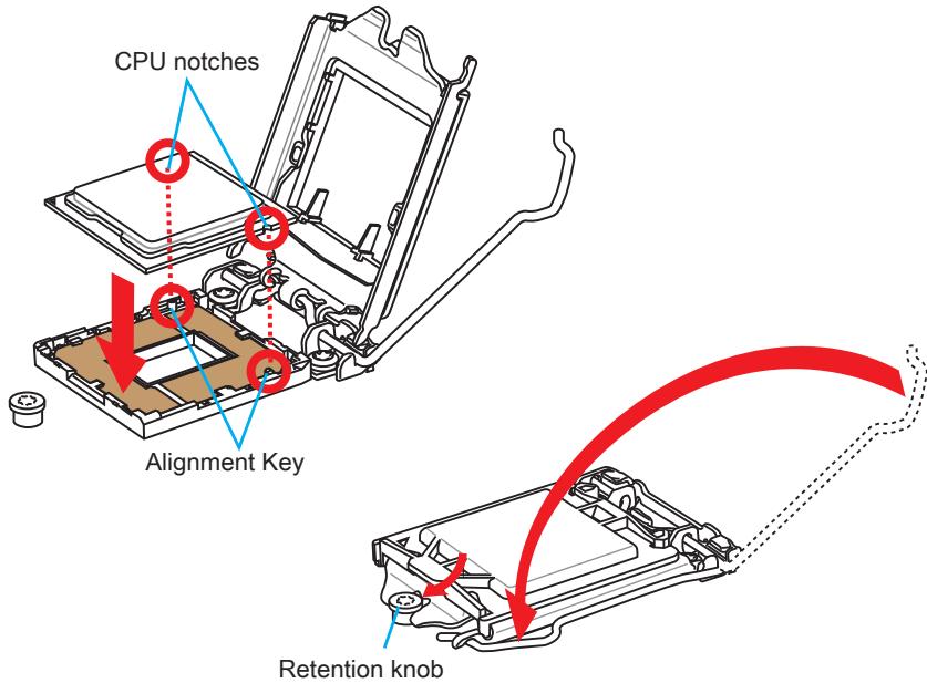
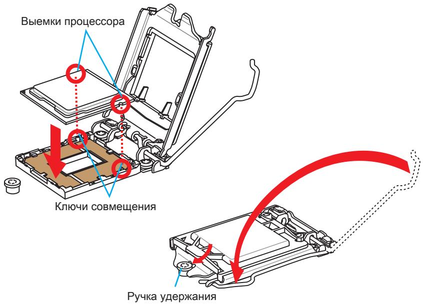
- Align the notches with the socket alignment keys. Lower the CPU straight down, without tilting or sliding the CPU in the socket. Inspect the CPU to check if it is properly seated in the socket.
- Close and slide the load plate under the retention knob. Close and engage the load lever.
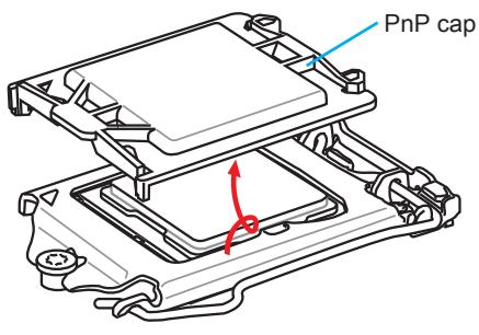
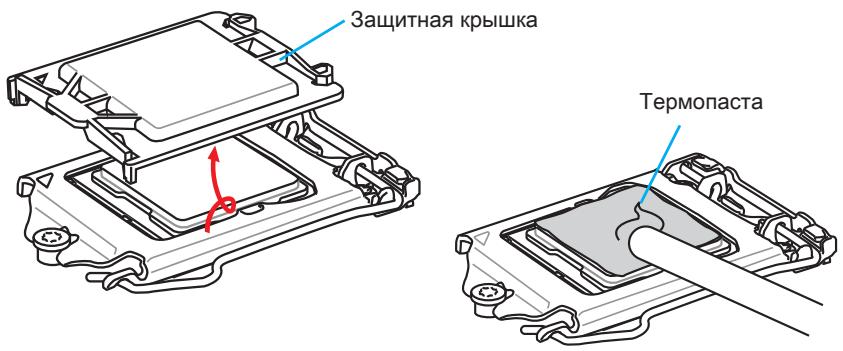
- When you press down the load lever the PnP cap will automatically pop up from the CPU socket. Do not discard the PnP cap. Always replace the PnP cap if the CPU is removed from the socket.
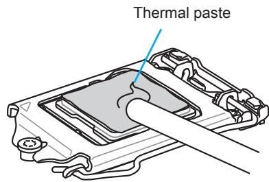
- Evenly spread a thin layer of thermal paste (or thermal tape) on the top of the CPU. This will help in heat dissipation and prevent CPU overheating.
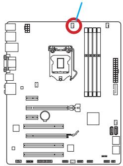
- Locate the CPU fan connector on the motherboard.
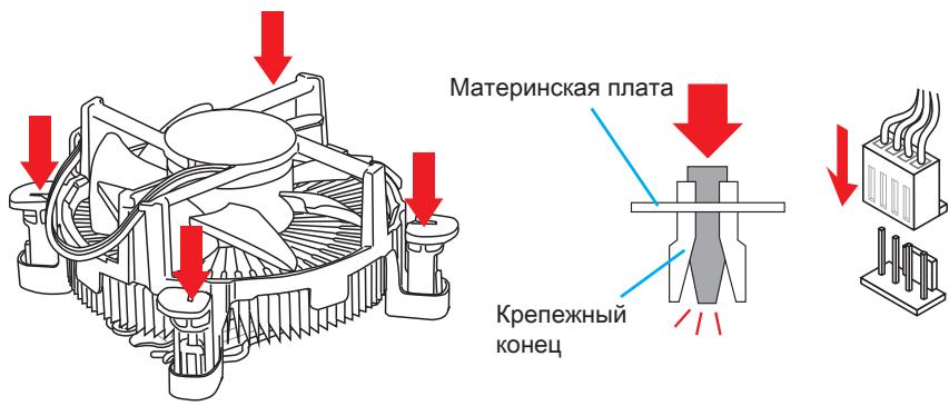
- Place the heatsink on the motherboard with the fan's cable facing towards the fan connector and the fasteners matching the holes on the motherboard.
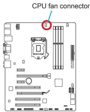
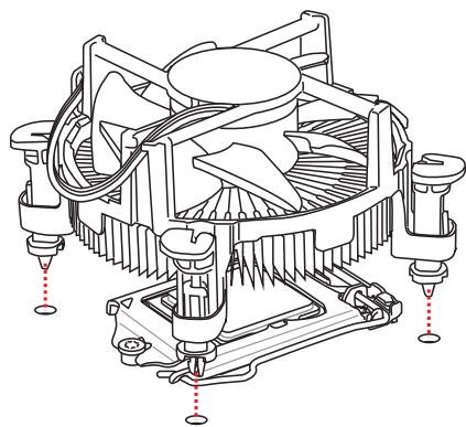
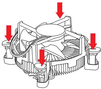
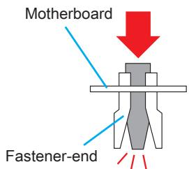
- Push down the heatsink until the four fasteners get wedged into the holes on the motherboard. Press the four fasteners down to fasten the heatsink. As each fastener locks into position a click should be heard.
- Inspect the motherboard to ensure that the fastener-ends have been properly locked in place.
- Finally, attach the CPU fan cable to the CPU fan connector on the motherboard.

Important
- Confirm that the CPU heatsink has formed a tight seal with the CPU before booting your system.
- Whenever the CPU is not installed, always protect the CPU socket pins by covering the socket with the plastic cap.
- If you purchased a separate CPU and heatsink/ cooler, Please refer to the documentation in the heatsink/ cooler package for more details about installation.
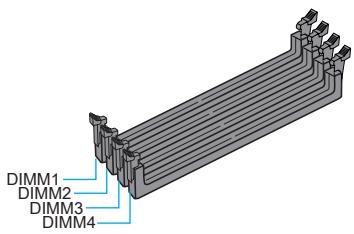
Memory
These DIMM slots are used for installing memory modules. For more information on compatible components, please visit http://www.msi.com/service/test-report/

Video Demonstration
Watch the video to learn how to install memories at the address below. http://youtu.be/76yLtJaKICQ

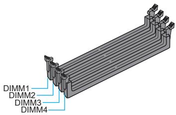
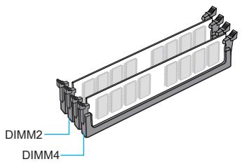
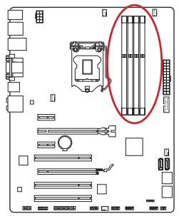
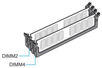
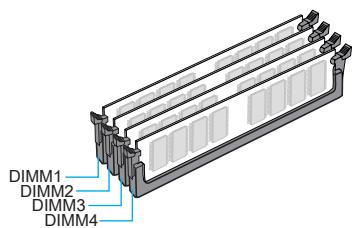
Dual-Channel mode Population Rule
In Dual-Channel mode, the memory modules can transmit and receive data with two data bus channels simultaneously. Enabling Dual-Channel mode can enhance system performance. The following illustrations explain the population rules for Dual-Channel mode.


Important
- DDR3 memory modules are not interchangeable with DDR2, and the DDR3 standard is not backward compatible. Always install DDR3 memory modules in DDR3 DIMM slots.
- To ensure system stability, memory modules must be of the same type and density in Dual-Channel mode.
- Due to chipset resource usage, the system will only detect up to 31+ GB of memory (not full 32 GB) when all DIMM slots have 8GB memory modules installed.
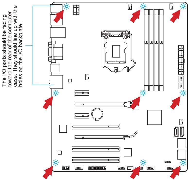
Mounting Screw Holes
When installing the motherboard, first install the necessary mounting stands required for an motherboard on the mounting plate in your computer case. If there is an I/O back plate that came with the computer case, please replace it with the I/O backplate that came with the motherboard package. The I/O backplate should snap easily into the computer case without the need for any screws. Align the mounting plate's mounting stands with the screw holes on the motherboard and secure the motherboard with the screws provided with your computer case. The locations of the screw holes on the motherboard are shown below. For more information, please refer to the manual that came with the computer case.

Important
- Install the motherboard on a flat surface free from unnecessary debris.
- To prevent damage to the motherboard, any contact between the motherboard circuitry and the computer case, except for the mounting stands, is prohibited.
- Please make sure there are no loose metal components on the motherboard or within the computer case that may cause a short circuit of the motherboard.

Video Demonstration
Watch the video to learn how to install power supply connectors. http://youtu.be/gkDYyR_8314

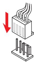
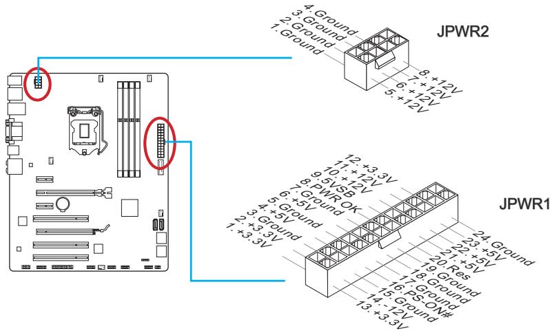
JPWR1~2:ATX Power Connectors
These connectors allow you to connect an ATX power supply. To connect the ATX power supply, align the power supply cable with the connector and firmly press the cable into the connector. If done correctly, the clip on the power cable should be hooked on the motherboard's power connector.

Important
Make sure that all the power cables are securely connected to a proper ATX power supply to ensure stable operation of the motherboard.
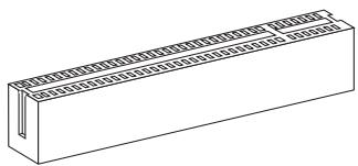
Expansion Slots
This motherboard contains numerous slots for expansion cards, such as discrete graphics or audio cards.
PCI_E1~E4: PCIe Expansion Slot
The PCIe slot supports the PCIe interface expansion card.
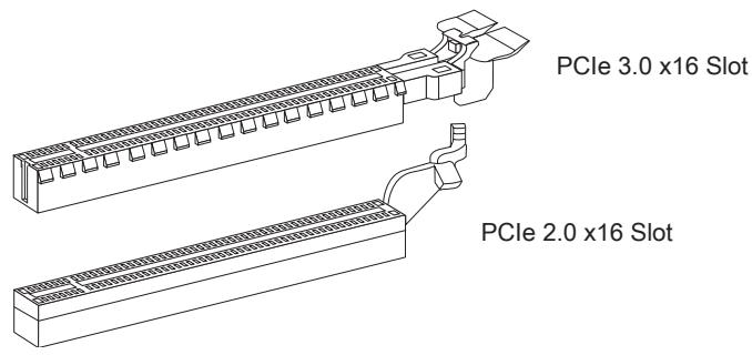
PCIe 2.0 x1 Slot
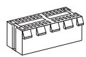
PCI1~3: PCI Expansion Slot
The PCI slot supports additional LAN, SCSI, USB, and other add-on cards that comply with PCI specifications.

Important
When adding or removing expansion cards, always turn off the power supply and unplug the power supply power cable from the power outlet. Read the expansion card's documentation to check for any necessary additional hardware or software changes.
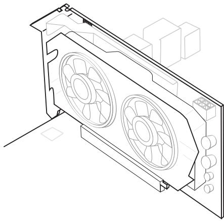
If available, this motherboard takes advantage of the CPU's integrate graphics processor, but discrete video cards can be installed by way of the motherboard's expansion slots. Adding on one or more discrete video cards will significantly boost the system's graphics performance. For best compatibility, MSI graphics cards are recommended.

Video Demonstration
Watch the video to learn how to install a graphics card on PCIe x16 slot with butterfly lock.
http://youtu.be/mG0GZpr9w_A

Single Video Card Installation
- Determine what type of expansion slot(s) the video card will use. Locate the expansion slot(s) on the motherboard. Remove any protective expansion slot covers from the computer case.
- Line up the video card on top of the expansion slot(s) with the display ports facing out of the computer case. For a single video card installation, using the PCI_E2 slot is recommended.
- Push the video card into its expansion slot(s). Depending on the expansion slot(s) used, there should be clip(s) on the expansion slot(s) that will lock in place.
- If needed, screw the edge of the graphics card to the computer case. Some video cards might require a power cable directly from the power supply.
- Please consult your video card's manual for further instructions regarding driver installation or other special settings.
SATA1~6: SATA Connector
This connector is a high-speed SATA interface port. Each connector can connect to one SATA device. SATA devices include disk drives (HDD), solid state drives (SSD), and optical drives (CD/DVD/Blu-Ray).

Video Demonstration
Watch the video to learn how to Install SATA HDD. http://youtu.be/RZsMpqxthyc

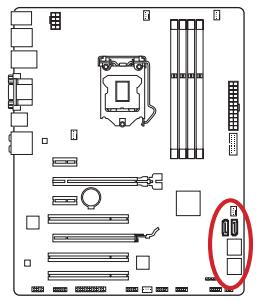
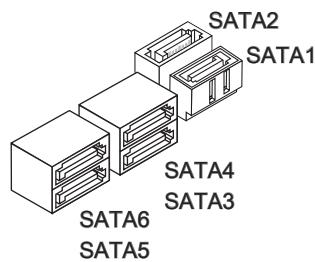
SATA1~6 (6Gb/s) by Intel® Z87/H87
SATA1~4 (6Gb/s), SATA5~6 (3Gb/s) by Intel® B85

Important
- Many SATA devices also need a power cable from the power supply. Such devices include disk drives (HDD), solid state drives (SSD), and optical drives (CD / DVD / Blu-Ray). Please refer to the device's manual for further information.
- Many computer cases also require that large SATA devices, such as HDDs, SSDs, and optical drives, be screwed down into the case. Refer to the manual that came with your computer case or your SATA device for further installation instructions.
- Please do not fold the SATA cable at a 90-degree angle. Data loss may result during transmission otherwise.
- SATA cables have identical plugs on either sides of the cable. However, it is recommended that the flat connector be connected to the motherboard for space saving purposes.
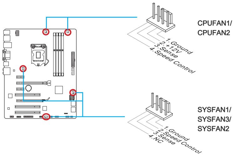
CPUFAN1~2,SYSFAN1~3: Fan Power Connectors
The fan power connectors support system cooling fans with +12V. If the motherboard has a System Hardware Monitor chipset on-board, you must use a specially designed fan with a speed sensor to take advantage of the CPU fan control. Remember to connect all system fans. Some system fans may not connect to the motherboard and will instead connect to the power supply directly. A system fan can be plugged into any available system fan connector.

Important
- Please refer to your processor's official website or consult your vendor to find recommended CPU heatsink.
- These connectors support Smart Fan Control with liner mode. The Command Center utility can be installed to automatically control the fan speeds according to the CPU's and system's temperature.
- If there are not enough ports on the motherboard to connect all system fans, adapters are available to connect a fan directly to a power supply.
- Before first boot up, ensure that there are no cables impeding any fan blades.
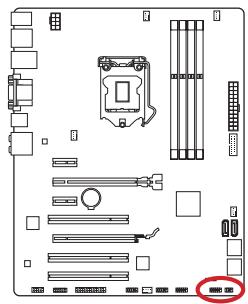
JFP1, JFP2: System Panel Connectors
These connectors connect to the front panel switches and LEDs. The JFP1 connector is compliant with the Intel® Front Panel I/O Connectivity Design Guide. When installing the front panel connectors, please use the optional M-Connector to simplify installation. Plug all the wires from the computer case into the M-Connector and then plug the M-Connector into the motherboard.

Video Demonstration
Watch the video to learn how to Install front panel connectors. http://youtu.be/DPELldVNZUI


Important
- On the connectors coming from the case, pins marked by small triangles are positive wires. Please use the diagrams above and the writing on the optional M-Connectors to determine correct connector orientation and placement.
- The majority of the computer case's front panel connectors will primarily be plugged into JFP1.
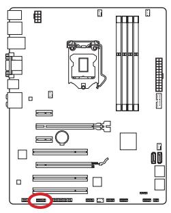
JUSB1~2: USB 2.0 Expansion Connector
This connector is designed for connecting high-speed USB peripherals such as USB HDDs, digital cameras, MP3 players, printers, modems, and many others.
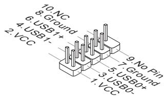

Important
Note that the VCC and GND pins must be connected correctly to avoid possible damage.
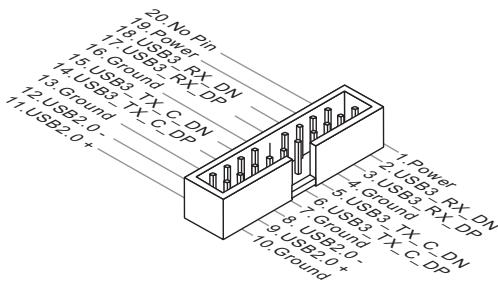
JUSB3: USB 3.0 Expansion Connector
The USB 3.0 port is backwards compatible with USB 2.0 devices. It supports data transfer rates up to 5Gbits/s (SuperSpeed).
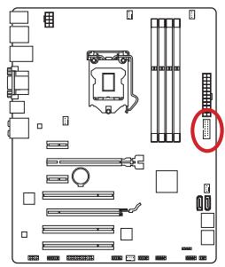

Important
- Note that the VCC and GND pins must be connected correctly to avoid possible damage.
- To use a USB 3.0 device, you must connect the device to a USB 3.0 port through an optional USB 3.0 compliant cable.
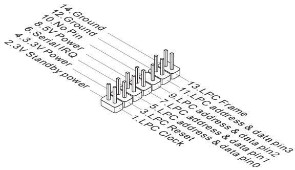
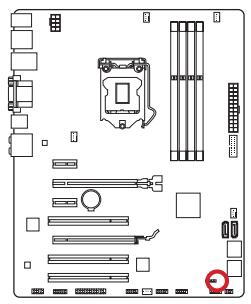
JTPM1: TPM Module Connector
This connector connects to a optional TPM (Trusted Platform Module) Module. Please refer to the TPM security platform manual for more details and usages.
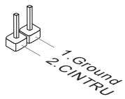
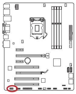
JCI1: Chassis Intrusion Connector
This connector connects to the chassis intrusion switch cable. If the computer case is opened, the chassis intrusion mechanism will be activated. The system will record this intrusion and a warning message will flash on screen. To clear the warning, you must enter the BIOS utility and clear the record.
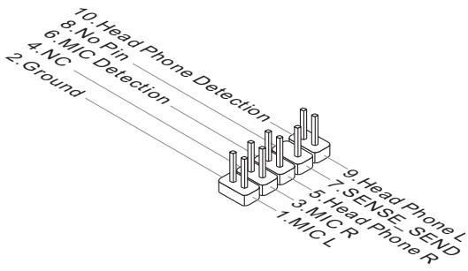
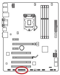
JAUD1: Front Panel Audio Connector
This connector allows you to connect the front audio panel located on your computer case. This connector is compliant with the Intel® Front Panel I/O Connectivity Design Guide.
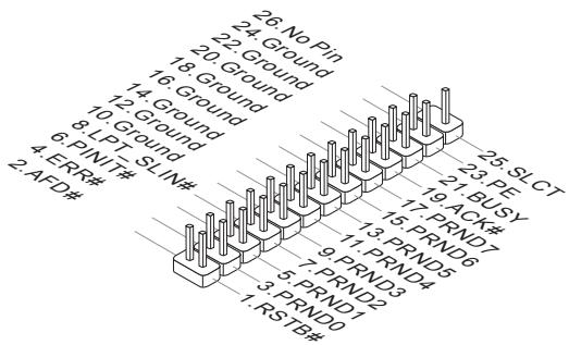
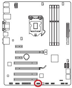
JLPT1: Parallel Port Connector
This connector is used to connect an optional parallel port bracket. The parallel port is a standard printer port that supports Enhanced Parallel Port (EPP) and Extended Capabilities Parallel Port (ECP) mode.
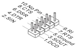
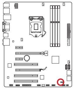
JCOM1: Serial Port Connector
This connector is a 16550A high speed communication port that sends/receives 16 bytes FIFOs. You can attach a serial device.
JBAT1: Clear CMOS Jumper
There is CMOS RAM onboard that is external powered from a battery located on the motherboard to save system configuration data. With the CMOS RAM, the system can automatically boot into the operating system (OS) every time it is turned on. If you want to clear the system configuration, set the jumpers to clear the CMOS RAM.

Keep Data

Clear Data

Important
You can clear the CMOS RAM by shorting this jumper while the system is off. Afterwards, open the jumper. Do not clear the CMOS RAM while the system is on because it will damage the motherboard.
After you install the operating system you will need to install drivers to maximize the performance of the new computer you just built. MSI motherboard comes with a Driver Disc. Drivers allow the computer to utilize your motherboard more efficiently and take advantage of any special features we provide.
You can protect your computer from viruses by installing the bundled security program. The bundle also includes a variety of powerful and creative utilities.
Total Installer
Total Installer is very easy to use and does a great job of finding necessary drivers. Please follow the steps below to install drivers and utilities for your new computer.
- Insert MSI Driver Disc into the optical drive. The setup screen will automatically appear if autorun is enabled in OS.
- Click Total Installer. A popup dialogue will appear listing all necessary drivers.
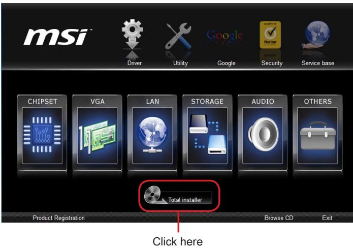
- Select all checkbox on driver listing dialog.
- Click Install button.
- The software installation will then be in progress, after it has finished it will prompt you to restart.
- Click OK button to finish.
- Restart your computer.
You can also use the same method to install the utilities.
CLICK BIOS is developed by MSI that provides a graphical user interface for setting parameters of BIOS by using the mouse and the keyboard.
With the CLICK BIOS, users can change BIOS settings, monitor CPU temperature, select the boot device priority and view system information such as the CPU name, DRAM capacity, the OS version and the BIOS version. Users can import and export parameters data for backup or sharing with friends.
Entering BIOS Setup
Power on the computer and the system will start the Power On Self Test (POST) process. When the message below appears on the screen, please key to enter BIOS:
If the message disappears before you respond and you still need to enter BIOS, restart the system by turning the computer OFF then back ON or pressing the RESET button. You may also restart the system by simultaneously pressing , , and keys.
MSI additionally provides two methods to enter the BIOS setup. You can click the "GO2BIOS" tab on "MSI Fast Boot" utility screen or press the physical "GO2BIOS" button (optional) on the motherboard to enable the system going to BIOS setup directly at next boot.
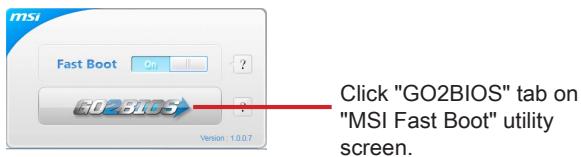

Important
- Please be sure to install the "MSI Fast Boot" utility before using it to enter the BIOS setup.
- The items under each BIOS category described in this chapter are under continuous update for better system performance. Therefore, the description may be slightly different from the latest BIOS and should be held for reference only.
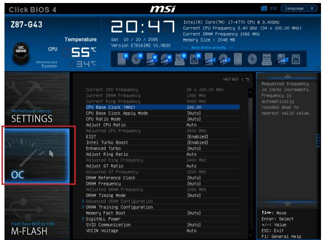
Overview
After entering BIOS, the following screen is displayed.
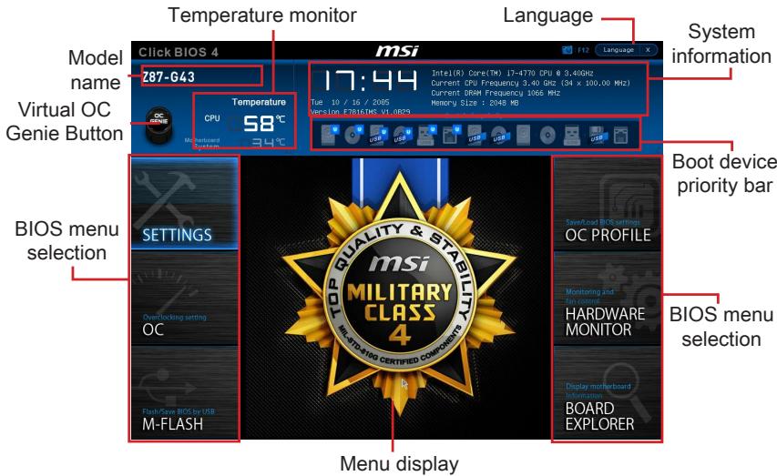
Temperature monitor
Shows the temperatures of the processor and the motherboard.
Language
Allows you to select the language of the BIOS setup.
System information
Shows the time, date, CPU name, CPU frequency, DRAM frequency, DRAM capacity and the BIOS version.
BIOS menu selection
The following options are available:
- SETTINGS - Uses this menu to specify the parameters for chipset and boot devices.
- OC - This menu contains the frequency and voltage adjustments. Increasing the frequency can get better performance, however high frequency and heat can cause instability, we do not recommend general users to overclock.
- M-FLASH - This menu provides the way to update BIOS with a USB flash disk.
OC PROFILE -This menu is used to set various overclocking profiles.
- HARDWARE MONITOR - This menu is used to set the speeds of fans and monitor voltages of system.
BOARD EXPLORER - It will provide the information of the installed devices on the motherboard.
Boot device priority bar
You can move the device icons to change the boot priority.

High priority Low priority
Menu display
This area provides BIOS settings and information to be configured.
Virtual OC Genie Button
Enables or disables the OC Genie function by clicking on this button. When enabled, this button will be light. Enabling OC Genie function can automatically overclock with MSI optimized overclocking profile.

Important
- We recommend that you do not to make any modification in OC menu and do not to load defaults after enabling the OC Genie function.
- Updating BIOS or clearing CMOS is not allowed in OC Genie mode, and it may cause OC Genie function fail or other effect.
Model Name
Shows the model name of motherboard.
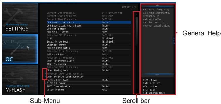
Sub-menu
If you find a point symbol to the left of certain items, that means a sub-menu can be launched for additional options. You can use the arrow keys or mouse to highlight the item and press or double-click the left mouse button to enter the sub-menu.
Scroll bar
Slide the scroll bar or use the arrow keys to display the other items that are available on the "menu display" area.
General Help
The General Help displays a brief description to assist you in grasping the selected item.
Operation
You can control BIOS settings with the mouse and the keyboard. The following table lists and describes the hot keys and the mouse operations.
| Hot key | Mouse | Description |
| <↑↓→←> | Move the cursor | Select Item |
| <Enter> | Click/ Double-click the left button | Select Icon/ Field |
| <Esc> | Click the right button | Jump to the Exit menu or return to the previous from a submenu |
| <++> | | Increase the numeric value or make changes |
| <-> | Decrease the numeric value or make changes |
| <F1> | General Help |
| <F4> | CPU Specifications |
| <F5> | Enter Memory-Z |
| <F6> | Load optimized defaults |
| <F8> | OC Profile Load From USB |
| <F9> | OC Profile Save to USB |
| <F10> | Save Change and Reset |
| <F12> | Save a screenshot to a FAT/FAT32 USB drive |
This menu is for advanced users who want to overclock the mainboard.

Important
- Overclocking your PC manually is only recommended for advanced users.
- Overclocking is not guaranteed, and if done improperly, can void your warranty or severely damage your hardware.
- If you are unfamiliar with overclocking, we advise you to use OC Genie for easy overclocking.
Current CPU/ DRAM/ Ring Frequency
These items show the current frequencies of installed CPU and Memory. Read-only.
CPU Base Clock (MHz) [Default]
Sets the CPU Base clock. You may overclock the CPU by adjusting this value. Please note that overclocking behavior and stability is not guaranteed. This item appears when the installed processor supports this function.
Current CPU Base Clock Strap (Z87-G43)
Shows the current CPU Base clock strap. Read only. This item can only be changed if the processor supports this function.
Adjust CPU Base Clock Strap [Auto] (Z87-G43)
Sets the CPU Base Clock Strap. You may overclock the CPU Base Clock by adjusting this value. Please note that overclocking behavior and stability is not guaranteed. This item can only be changed if the processor supports this function. If set to "Auto", BIOS will configure this setting automatically. [Options: Auto, 1.00, 1.25, 1.67]
CPU Base Clock Apply Mode [Auto]
Sets the applying mode for adjusted CPU base clock.
[Auto] This setting will be configured automatically by BIOS.
[Next Boot] CPU will run the adjusted CPU base clock after reboot.
[Immediate] CPU runs the adjusted CPU base clock immediately.
- CPU PCIE PLL [Auto] (Z87-G43)
Selects a PLL (Phase Lock Loop) mode for CPU PCIe. This item appears when the installed CPU supports this setting.
[Auto] This setting will be configured automatically by BIOS.
[LC PLL] Enables LC PLL for normal usage.
[S BPLL] Enables SB PLL for extreme overclocking.
Filter PLL [Auto] (Z87-G43)
Enables or disables the filter PLL for CPU. This item appears when the installed CPU supports this setting.
[Auto] This setting will be configured automatically by BIOS.
[Enabled] Provides wide range of base clock for overclocking when base clock strap be set to higher value.
[Disabled] Provides normal range of base clock.
CPU Ratio Mode [Auto]
Selects the CPU Ratio operating mode.
[Auto] This setting will be configured automatically by BIOS.
[Fixed Mode] Fits the CPU ratio.
[Dynamic Mode] CPU ratio will be changed dynamically according to the CPU loading.
Adjust CPU Ratio [Auto]
Sets the CPU ratio that is used to determine CPU clock speed. This item can only be changed if the processor supports this function.
Adjusted CPU Frequency
Shows the adjusted CPU frequency. Read-only.
EIST [Enabled]
Enables or disables the Enhanced Intel® SpeedStep Technology.
[Enabled] Enables the EIST to adjust CPU voltage and core frequency dynamically. It can decrease average power consumption and average heat production.
[Disabled] Disables EIST.
Intel Turbo Boost [Enabled]
Enables or disables the Intel® Turbo Boost. This item appears when the installed CPU supports this function.
[Enabled] Enables this function to boost CPU performance automatically above rated specifications when system request the highest performance state.
[Disabled] Disables this function.
Enhanced Turbo [Auto]
Enables or disables Enhanced Turbo function for all CPU cores to boost CPU performance.
[Auto] This setting will be configured automatically by BIOS.
[Enabled] All CPU cores would be increased to maximum turbo ratio.
[Disabled] Disables this function.
Adjust Ring Ratio [Auto]
Sets the ring ratio. The valid value range depends on the installed CPU.
Adjusted Ring Frequency
Shows the adjusted Ring frequency. Read-only.
Adjust GT Ratio [Auto]
Sets the integrated graphics ratio. The valid value range depends on the installed CPU.
Adjusted GT Frequency
Shows the adjusted integrated graphics frequency. Read-only.
DRAM Reference Clock [Auto]
Sets the DRAM reference clock. The valid value range depends on the installed CPU.
This item appears when a CPU that supports this adjustment is installed.
DRAM Frequency [Auto]
Sets the DRAM frequency. Please note the overclocking behavior is not guaranteed.
Adjusted DRAM Frequency
Shows the adjusted DRAM frequency. Read-only.
Extreme Memory Profile (X.M.P) [Disabled]
X.M.P. (Extreme Memory Profile) is the overclocking technology by memory module. This item will be available when you install the memory modules that support X.M.P. technology.
[Disabled] Disables this function.
[Profile 1] Uses profile1 over-clocking settings of installed XMP memory module.
[Profile 2] Uses profile2 over-clocking settings of installed XMP memory module.
DRAM Timing Mode [Auto]
Selects the memory timing mode.
[Auto] DRAM timings will be determined based on SPD (Serial Presence Detect) of installed memory modules.
[Link] Allows user to configure the DRAM timing manually for all memory channel.
[UnLink] Allows user to configure the DRAM timing manually for respective memory channel.
Advanced DRAM Configuration
Press to enter the sub-menu. This sub-menu will be activated after setting [Link] or [Unlink] in "DRAM Timing Mode". User can set the memory timing for each memory channel. The system may become unstable or unbootable after changing memory timing. If it occurs, please clear the CMOS data and restore the default settings. (Refer to the Clear CMOS jumper/ button section to clear the CMOS data, and enter the BIOS to load the default settings.)
DRAM Training Configuration
Press to enter the sub-menu. Enables or disables the various training ways of DRAM. The system may become unstable or unbootable after changing these items in this sub-menu. If it occurs, please clear the CMOS data and restore the default settings. (Refer to the Clear CMOS jumper/ button section to clear the CMOS data, and enter the BIOS to load the default settings.)
Memory Fast Boot [Auto]
Enables or disables the initiation and training for memory every booting.
[Auto] This setting will be configured automatically by BIOS.
[Enabled] Memory will completely imitate the archive of first initiation and first training. After that, the memory will not be initialed and trained when booting to accelerate the system booting time.
[Disabled] The memory will be initialed and trained every booting.
DigitALL Power
Press to enter the sub-menu. Controls the digital powers related to CPU PWM.
CPU Phase Control [Auto]
Controls PWM phase proportionally to the CPU loading. If set to "Auto", BIOS will optimize the CPU PWM phase automatically.
[Auto] This setting will be configured automatically by BIOS.
[Disabled] Disables the PWM power phase switching feature.
CPU Vdroop Offset Control [Auto]
Sets a percentage of offset voltage for CPU vdroop. If set to "Auto", BIOS will configure this setting automatically. [Options: Auto, +12.5%, +25%, +37.5%, +50%, +62.5%, +75%, +87.5%, +100%]
CPU Over Voltage Protection [Auto]
Sets the voltage limit for CPU over-voltage protection. If set to "Auto", BIOS will configure this setting automatically. Higher voltage provides less protection and may damage the system.
CPU Under Voltage Protection [Auto]
Sets the voltage limit for CPU under-voltage protection. If set to "Auto", BIOS will configure this setting automatically. Higher voltage provides less protection and may damage the system.
CPU Over Current Protection [Auto]
Sets the current limit for CPU over-current protection. If set to "Auto", BIOS will configure this setting automatically. Higher percentage provides less protection and may damage the system.
Phase Over Current Protection [Enabled]
Enables or disables the phase over-current protection.
[Enabled] Sets the current limit on the phase for over-current protection.
[Disabled] Disables this function.
CPU Switching Frequency [Auto]
Sets the PWM working speed to stabilize CPU Core voltage and minimize ripple range. Increasing the PWM working speed will cause higher temperature of MOSFET. So please make sure a cooling solution is well-prepared for MOSFET before you increase the value. If set to "Auto", BIOS will configure this setting automatically.
CPU VRM Over Temperature Protection [Enabled]
Enables or disables the CPU VRM over-temperature protection.
[Enabled] Sets the temperature limit on CPU VRM for over-temperature protection.
[Disabled] Disables this function.
Digital Compensation Level [Auto]
Sets the current compensation level for CPU PWM when the MOS phases are changed. If set to "Auto", BIOS will configure this setting automatically. Higher compensation level provides more overclocking ability.
Imon Overwrite [Auto]
Sets the lmon current for CPU.
[Auto] This setting will be configured automatically by BIOS.
[Quarter] Sets the lmon current into quarter.
[Half] Sets the lmon current into half.
[Disabled] Sets the default values for lmon current.
Transient Boost [Disabled]
Enables or disables the transient boost.
[Enabled] Enables this function may lead into a stable system under heavy system loading.
[Disabled] Disables this function.
SVID Communication [Auto]
Enables or disables SVID (Serial Voltage Identification) support.
[Auto] This setting will be configured automatically by BIOS.
[Enabled] PWM phase will be changed dynamically according to the CPU SVID (Serial Voltage Identification).
[Disabled] Disables SVID (Serial Voltage Identification) support.
VCCIN Voltage [Auto]
Sets the CPU input voltage. The CPU input voltage is the CPU power source that is shared with components of the CPU.
Current VCCIN Voltage
Shows current CPU VCCIN voltage. Read-only.
- CPU Core Voltage Mode/ CPU Ring Voltage Mode/ CPU GT Voltage Mode [Auto]
Selects the control modes for these voltages.
[Auto] This setting will be configured automatically by BIOS.
[Adaptive Mode] Sets adaptive voltages automatically for optimizing the system performance.
[Override Mode] Allows you to set these voltages manually.
CPU Core Voltage/ CPU Ring Voltage/ CPU GT Voltage [Auto]
Sets these voltages. If set to "Auto", BIOS will set these voltages automatically or you can set it manually.
- CPU Core Voltage Offset Mode/ CPU Ring Voltage Offset Mode/ CPU GT Voltage Offset Mode/ CPU SA Voltage Offset Mode/ CPU IO Analog Voltage Offset Mode/ CPU IO Digital Voltage Offset Mode [Auto]
Selects the voltage offset modes.
[Auto] This setting will be configured automatically by BIOS.
[+] Allows you to set the positive offset voltage.
[-] Allows you to set the negative offset voltage.
- CPU Core Voltage Offset/ CPU Ring Voltage Offset/ CPU GT Voltage Offset/ CPU SA Voltage Offset/ CPU IO Analog Voltage Offset/ CPU IO Digital Voltage Offset [Auto]
Set the offset values for these voltages.
Current CPU Core Voltage/ Current CPU Ring Voltage/ Current CPU GT Voltage/ Current CPU SA Voltage/ Current CPU IO Digital Voltage
Show the current voltages. Read-only.
Internal VR OVP OCP Protection [Auto]
Enables or disables the over-voltage protection and over-current protection for CPU internal VR (Voltage Regulator).
[Auto] This setting will be configured automatically by BIOS.
[Enabled] Sets the voltage limit on the CPU internal VR for over-voltage protection and over-current protection.
[Disabled] Disables this function for overclocking.
Internal VR Efficiency Management [Auto]
Enables or disables the CPU internal VR efficiency management.
[Auto] This setting will be configured automatically by BIOS.
[Enabled] Enables the VR efficiency management for power-saving control.
[Disabled] Disables this function.
DRAM Voltage [Auto]
Sets the memory voltage. If set to "Auto", BIOS will set memory voltage automatically or you can set it manually.
Current DRAM Voltage
Shows current memory voltage. Read only.
- DDR_VREF_CA/ DDR_VREF_DQ_A/ DDR_VREF_DQ_B/ PCH 1.05 Voltage/ PCH 1.5 Voltage
Set these voltages. If set to "Auto", BIOS will set these voltages automatically or you can set it manually.
Current PCH 1.05 Voltage
Shows current PCH 1.05 voltage. Read only.
CPU Memory Changed Detect [Enabled]
Enables or disables the system to issue a warning message during boot when the CPU or memory has been replaced.
[Enabled] The system will issue a warning message during boot and then needs to load the default settings for new devices.
[Disabled] Disables this function and keeps the current BIOS settings.
Spread Spectrum
This function reduces the EMI (Electromagnetic Interference) generated by modulating clock generator pulses.
[Enabled] Enables the spread spectrum function to reduce the EMI (Electromagnetic Interference) problem.
[Disabled] Enhances the overclocking ability of CPU Base clock.
![MSI B85-G43 - Phase Over Current Protection [Enabled] - 1](/content/2019/06/199139/images/2c8fceea3c1360f2ee54537479715834ad319cdd69a7480dbe86cc6200a31656.jpg)
Important
- If you do not have any EMI problem, leave the setting at [Disabled] for optimal system stability and performance. But if you are plagued by EMI, select the value of Spread Spectrum for EMI reduction.
- The greater the Spread Spectrum value is, the greater the EMI is reduced, and the system will become less stable. For the most suitable Spread Spectrum value, please consult your local EMI regulation.
- Remember to disable Spread Spectrum if you are overclocking because even a slight jitter can introduce a temporary boost in clock speed which may just cause your overclocked processor to lock up.
CPU Specifications
Press to enter the sub-menu. This sub-menu displays the information of installed CPU. You can also access this information menu at any time by pressing [F4]. Read only.
CPU Technology Support
Press to enter the sub-menu. The sub-menu shows what the key features does the installed CPU support. Read only.
MEMORY-Z
Press to enter the sub-menu. This sub-menu displays all the settings and timings of installed memory. You can also access this information menu at any time by pressing [F5].
DIMM1~4 Memory SPD
Press to enter the sub-menu. The sub-menu displays the information of installed memory. Read only.
CPU Features
Pressto enter the sub-menu.
Hyper-Threading Technology [Enabled]
The processor uses Hyper-Threading technology to increase transaction rates and reduces end-user response times. Intel Hyper-Threading technology treats the multi cores inside the processor as multi logical processors that can execute instructions simultaneously. In this way, the system performance is highly improved.
[Enable] Enables Intel Hyper-Threading technology.
[Disabled] Disables this item if the system does not support HT function.
Active Processor Cores [All]
This item allows you to select the number of active processor cores.
Limit CPUID Maximum [Disabled]
Enables or disables the extended CPUID value.
[Enabled] BIOS will limit the maximum CPUID input value to circumvent boot problems with older operating system that do not support the processor with extended CPUID value.
[Disabled] Use the actual maximum CPUID input value.
Execute Disable Bit [Enabled]
Intel's Execute Disable Bit functionality can prevent certain classes of malicious "buffer overflow" attacks where worms attempt to execute code to damage the system. It is recommended that keeps this item enabled always.
[Enabled] Enables NO-Execution protection to prevent the malicious attacks and worms.
[Disabled] Disables this function.
> Intel Virtualization Tech [Enabled]
Enables or disables Intel Virtualization technology.
[Enabled] Enables Intel Virtualization technology and allows a platform to run multiple operating systems in independent partitions. The system can function as multiple systems virtually.
[Disabled] Disables this function.
Hardware Prefetcher [Enabled]
Enables or disables the hardware prefetcher (MLC Streamer prefetcher).
[Enabled] Allows the hardware prefetcher to automatically pre-fetch data and instructions into L2 cache from memory for tuning the CPU performance.
[Disabled] Disables the hardware prefetcher.
Adjacent Cache Line prefetch [Enabled]
Enables or disables the CPU hardware prefetcher (MLC Spatial prefetcher).
[Enabled] Enables adjacent cache line prefetching for reducing the cache latency time and tuning the performance to the specific application.
[Disabled] Enables the requested cache line only.
CPU AES Instructions [Enabled]
Enables or disables the CPU AES (Advanced Encryption Standard-New Instructions) support. This item appears when a CPU supports this function.
[Enabled] Enables Intel AES support.
[Disabled] Disables Intel AES support.
Intel Adaptive Thermal Monitor [Enabled]
Enables or disables the Intel adaptive thermal monitor function to protect the CPU from overheating.
[Enabled] Throttles down the CPU core clock speed when the CPU is over the adaptive temperature.
[Disabled] Disables this function.
Intel C-State [Enabled]
C-state is a processor power management technology defined by ACPI.
[Auto] This setting will be configured automatically by BIOS.
[Enabled] Detects the idle state of system and reduce CPU power consumption accordingly.
[Disabled] Disable this function.
C1E Support [Disabled]
Enables or disables the C1E function for power-saving in halt state. This item appears when "Intel C-Statel" is enabled.
[Enabled] Enables C1E function to reduce the CPU frequency and voltage for power-saving in halt state.
[Disabled] Disables this function.
Package C State limit [Auto]
This item allows you to select a CPU C-state mode for power-saving when system is idle. This item appears when "Intel C-State" is enabled.
[Auto] This setting will be configured automatically by BIOS.
[C0~C7s] The power-saving level from high to low is C7s, C7, C6, C3, C2, then C0.
[No limit] No c-state limit for CPU.
LakeTiny Feature [Disabled]
Enables or disables Intel Lake Tiny technology with iRST for SSD. This item appears when "Intel C-State" is enabled.
[Enabled] Enhance the dynamic IO load adjusted performance for accelerating the SSD speed.
[Disabled] Disables this feature.
Note: The following items will appear when "Intel Turbo Boost" is enabled.
Long Duration Power Limit (W) [Auto]
Sets the long duration TDP power limit for CPU in Turbo Boost mode.
Long Duration Maintained (s) [Auto]
Sets the maintaining time for "Long duration power Limit(W)".
Short Duration Power Limit (W) [Auto]
Sets the short duration TDP power limit for CPU in Turbo Boost mode.
CPU Current limit (A) [Auto]
Sets maximum current limit of CPU package in Turbo Boost mode. When the current is over the specified limit value, the CPU will automatically reduce the core frequency for reducing the current.
1/2/3/4-Core Ratio Limit [Auto]
These items only appear when a CPU that support this function is installed. These items allow you to set the CPU ratios for different number of active cores in turbo boost mode. These items appear when the installed processor supports this function.
JPWR1~2:ATX Stromanschlüsse
JFP1, JFP2: Frontpanel Anschlüsse
Current CPU/ DRAM/ Ring Frequency
Current CPU Base Clock Strap (Z87-G43)
Adjust CPU Ratio [Auto]
Adjusted CPU Frequency
Adjust Ring Ratio [Auto]
Adjusted Ring Frequency
Adjust GT Ratio [Auto]
Adjusted GT Frequency
Adjusted DRAM Frequency
CPU Phase Control [Auto]
Phase Over Current Protection [Enabled]
CPU VRM Over Temperature Protection [Enabled]
Current VCCIN Voltage
CPU Core Voltage/ CPU Ring Voltage/ CPU GT Voltage [Auto]
Current CPU Core Voltage/ Current CPU Ring Voltage/ Current CPU GT Voltage/ Current CPU SA Voltage/ Current CPU IO Digital Voltage
Internal VR Efficiency Management [Auto]
Current DRAM Voltage
Current PCH 1.05 Voltage
CPU Technology Support
> Adjacent Cache Line Prefetch [Enabled]
> Intel Adaptive Thermal Monitor [Enabled]
Intel C-State [Auto]
Long Duration Power Limit (W) [Auto]
Long Duration Maintained (s) [Auto]
Short Duration Power Limit (W) [Auto]
- CPU Current limit (A) [Auto]
Current CPU/ DRAM/ Ring Frequency
[Fixed Mode] Fixer le ratio CPU.
Adjust CPU Ratio [Auto]
Adjusted CPU Frequency
Adjust Ring Ratio [Auto]
Adjusted Ring Frequency
Adjust GT Ratio [Auto]
Adjusted GT Frequency
Adjusted DRAM Frequency
CPU Phase Control [Auto]
Active ou désactive le support SVID (Serial Voltage Identification).
[Disabled] Désactive le support SVID (Serial Voltage Identification).
VCCIN Voltage [Auto]
Current VCCIN Voltage
- Current CPU Core Voltage/ Current CPU Ring Voltage/ Current CPU GT Voltage/ Current CPU SA Voltage/ Current CPU IO Digital Voltage
Internal VR Efficiency Management [Auto]
Current DRAM Voltage
Current PCH 1.05 Voltage
CPU Technology Support
> Adjacent Cache Line prefetch [Enabled]
Active ou désactive le prefetcher matériel CPU (MLC Spatial prefetcher).
CPU AES Instructions [Enabled]
[Enabled] Active le support Intel AES.
[Disabled] Désactive le support Intel AES.
Intel Adaptive Thermal Monitor [Enabled]
Long Duration Power Limit (W) [Auto]
Long Duration Maintained (s) [Auto]
Short Duration Power Limit (W) [Auto]
CPU Current limit (A) [Auto]
YcTaHOBka LII paIaTOpa
Pn yctahOBke npoceccoopa o63aTeIbHO yCTAHOBtpe padnatop LPi.PaHATOP LII npedynpexkdaet neperepaBHeN uOeCneuBaET cTabNbHoCTb pa60Tb CNTeMbI. HnKe npEcdtabNeHb I NcTpyKUIN NO npabInbHOy YCTAHOBke npoceccopa n paHaTOpa LII.HenpaBnIbHaY cTaHOBKa npINBOiT K BbIXOy n3 cTpor npoceccopa n MATEPHCKO pIaNbl.

Buiero Demohetpalu
CmToPnTe BnDeo,HTO6bI y3HaTb KaK yCTaHOBuTb npoueccop N KyJIep: http://youtu.be/bf5La099url

He Tporai Te KOthakTbI pa3bema IJIN HnXkHe Yactn npoceccopa.
- BbipabHnTe BbIeMKn Ha npoueccope K KJIIOUAMN COBMeueHnHa COKeTe.
Onyctnte npoecccop BHN3, 6e3 haknoha nIN DBNKeHnnpoecccopa COKTe. IpoBepte HndexKHOCTb yCTaHOBKn npoecccopa B COkeTe.
- 3akpoTe n cDvHbTe npKmHy npactHy nop yky ykepaHna. 3akpoTe n 3aueNte pbyar fukcaun.
- Пи нахати на рьчаг Фнcaци 3ацптая крblшka abTomatчески ВсICКOTИЗ rHeZda npoceccopa. He bIbpaCbIaBaiTe 3aцntHyIO крblshky. Bcerda yctahabnBaIte 3aцntHyIO крblshky, ecIn npoceccop BbIHMaTcN 3COkTeA.
- PaBHOmePno HAnecnte ToHkIn CNoI TepMOnaCTbI (NJIIN TepMOJeHTy) Ha BepXHIOKpbIshky npouceccopa. 3To nO3BOJNT yBeJIuHTb TeIIPOnepeDaUy I npEdoTbPaTITpeperpeB npouceccopa.
- HauTe pa3bem dIy noKJIIOUeHnBEHTNJrTopa LII Ha MaTePNHcOJ Pnate.
- YctaHOBInTe KUneR Ha MaTePnHcKyI OIIaTy, HnPaBvB erO Ka6eJIb B CToPOHy pa3bema IJRA IOKJIIOUChENr BEHTUNlraTopa.
Pa3bem nodknquchna BHTNIJTOPA

- HaxmTe Ha paDnAtop cbepx TaK, YTO6bI 3aKePnITb YeTbIpe 3aUeKN B OTBepCTnX Ha MaTePHNCKo PnATE. HaxmTe Ha 3aUeJIKn DnIg 3aKePnJIeHnBEHTnJIyTopa. KaKdbI n3 3aUeJOK fHKcnpyeTcC xapAKTePnhIM UeJIyKom.
- Ocmotpnte MaTeepnHcKyU PnAty U ONpeJeNTe npaBnIbHoCTb 3akpePJIeHnna 3aJIMOB.
- И, наточ龟, полочик Кабель вентся за поз ECCOPA К разему вентся за на сост教职工празе.

BhIMaHHe
- Пелег вкlioоченem системы поверътг repmetиюctь coeINHeHЯ мжду поцeccopom И радиatopom.
- Ecnn npoueccop He yctaHOBJIe, Bcerda 3aunuauTe KOHTaKTbI npoueccopHoro COketa nlaactIKOBOK KpbIkoK.
- Ecnn Bbl npno6pei nOtdeIbHo npoceccop n npoceccopn Kyep, noDpo6hoe OncaHne yCTaHOBKn CM. B DokymeHTaCm N DaHHomy Kyepy.
Pa3bembl DIMM npedHa3nueHb Iyra YcTaHOBKn MoJyne namrtn. NpOpo6Hyu INΦopMaζIIO COBmecTmBix KOMnoHEHTax cM. Ha caIte http://www.msi.com/ service/test-report/

Buae O DeMoHepaH
CmOTpuTE BnDeo,yTo6bI y3HaTb KaK yCTaHOBnTb nAmrTb No yKa3aHHOMy aDpecy.
http://youtu.be/76yLtJaKICQ

IpaBnla 3aOpJIHeHnra He3d npn nCNoJIb3OBAHn nDByXkaHaJIbHOpeKIma Dual-Channel
BdBykHaHbHom pexmme Moyni namT moryt OndOBpeMeHNO nepeDaBaTb I
noLyatb daHbIe no Dvym KaHaNAM shNbl. BKnIOueHne DByxKaHaNbHoro peXIMa
Dual-Channel moKet nobicntb npOn3BOJNTelhOcTB cnCTembl. Ha pncyHKax HnKe
POKa3aHbI npabnla 3anONHeHn rHe3d nAmrTn npu nCpONb30aHm NByxKaHaNbHoro
peXIMa Dual-Channel.

BhIMaHHe
JPWR1~2:Pa3bem nITaHnA ATX
3Tn pa3bembl npedHa3hauehblIy nOdkluoyehna pa3bema nItaHNA ATX.ДЯ nOdkluoyehna ATX pa3bema nItaHNA COBmecTne Ka6JIb nItaHNA c pa3bEmOM npOchu 3akpennte erO.Ipn npabInbHom BblOnHeHHn nOdkluoyehna 3aueKka Ha ka6ene nItaHNA 3akpenlareTCB CINOBom pa3beme MaTePHNcKoI PnAbl.


BHIMAHUE
Дя obecne�еня StabnbHо npabToCnCTeMHOn PnTaBn npOBepbTe NaJekHOCTb NOKNUOeHry Bexc KaBeNei NtAHN K COOTBeTcByUOeMy 6IOKy NtAHN ATX.
CLOTbI pauchepenH
Current CPU/ DRAM/ Ring Frequency
3Tn 3JIeMeHbI NOKa3bIbAOT KekUne YactOTbY UCTaHOBJeHHOrO IpOcEccopa IN pAMrTN. 3Tn 3HaueHn Helb3r N3MeHrTb.
CPU Base Clock (MHz) [Default]
UctahOBka 6a30oB TAKTOB OuaCTOblI. IVImeHne 3TOro napametpa
obecneuBaet Bo3MOxHocb «pa3roHa」LII. Obpaaaem Baue BHMaHne Ha To,
yTO KOMnAHnHe rapaHTnpyeY cNeuHocb BbINOpHeHnPa3roHa n CtaBnJbHOCTb
CnCTeMbI. 3TOT nyHKT NOBJIeTcR, KOrda yCTaHOBJIeHHbI npOceccop NODepKInBaET
DaHHyO fYHKsIO.
Current CPU Base Clock Strap (Z87-G43)
Ioka3bIbaeT noIocy Tekyuei 6a3OBoJ uactOtbl. 3To 3NaHeHne HnB3a N3MeHnTb.
IV3meHHe NaHHoro NyHKta BO3MOxH0 TOnbKO B TOM Cnyae, ecIn npoecccop
noIdepXnBaet daHHUo fYHKUIO.
Adjust CPU Base Clock Strap [Auto] (Z87-G43)
UctaHOBka nolocb Tekyuie 6a3OBoJ uactTobl Ll. I3MeHeHne 3TOro napametpa
obecneuBaet BO3MOxHocBb pa3roHa) 6a3OBoJ taKTOB JcactTobl Ll. O6pauaem
BaWe BnMaHne Ha To, YTO KOMNaHn He rapaHTnpyE TcpeuHocBb BInOpJIHeHn
pa3roHa n CTaBnIbHOCT b CnCTeMbl. I3MeHeHne DaHHOro NyHKTa BO3MOxHo TOnkO
B Tom cIpyae, ecn npocccop PndepKnaBaET daHNHy o fynKciu. Ecnn 3HaueHne
yctaHOBJeHO B "Auto", BIOS aBTomatueckn HacTpont 3OT napametp. [Onzhi:
Auto, 1.00, 1.25, 1.67]
Base Clock Apply Mode [Auto]
YctaHaBJIbAeT cnooc6 npimeHnI3MeHnI dIy KoppeKtnpOBKn 6a3OBoi YacToBi LII.
[Auto] 3TOT napameTp 6ydt HacTpoe n ABTOMaTHuecKn c NOMOuBIOBIS.
[Next Boot] Ipoceccop nepeienet ha ckoppeKtnpOBAHHyIO 6a3OBYIO qactOtTy LII nocne nepe3arpy3KN.
[LCPLL] BkIoucheHne LC PLL nIe HopMaJIbHorO nCOnb3ObaHnA.
[S BPLL] BknHueHne SB PLL dIy 3KCTpeMaJIbHO rO pa3roHa.
Filter PLL [Auto] (Z87-G43)
BkHoueHne Hn BbKIOUeHne 0nlbtpa PLL IJI. 3TOT nyHKT noRbIeTc, KOrda yCTaHOBHeHHb npOceccop nOdEepXnBaet n3MeHHe NaHHro npaMeTpa.
[Auto] Iapametp 6ydt Hactpoeh aBToMaTHueckn C nOmoIbBIOS.
Adjust CPU Ratio [Auto]
3aàanhe MHOXHTeI npoecccopa IyraTahOBN erToTbI npoecccopa.
I3meHHe NaHHoro napameTpa BO3MOxHO TOJIbKO B TOM cIyue, ecnI pOuceCOP IOndePKBaet daHNHyO fYHKUIO.
Adjusted CPU Frequency
Ioka3bIbaeTeKyuUyuaCTOTyL.3To 3HaueHHe HeJIb3aN3MeHrTb.
EIST [Enabled]
BkIouHne IIN BbIKIOUeHne TeXHOJOrnEnhanced Intel SpeedStep.
[Enabled] Bknouehne EIST dnypeynpovBkn HnpanjKeHn yacToTb npoeccopa. 3TOT nyhKT MOKET CHN3NtB cpeDHee 3hepronotpe6JIeHne n TenNo.
[Disabled] BbIKnOueHne EIST.
> Intel Turbo Boost [Enabled]
BknioHne HnBbKIOUcHHe Intel Turbo Boost. 3ToT nyHKT NOABJIeTc, KOrda yctahOBHeHHbI npOceccop NoIDepkXnBaET daHNHyO fynKcuio.
[Enabled] BkIouHeHne 3ToI ΦyHKcII npINBOIDNT K aBTOMaTNUeCKOMy yBcIIuueHIO npOn3BOIDNTeJIbHOCTn pOceCCopa.
[Disabled] ΦyHKnY BbIKIIOHeHa.
Enhanced Turbo [Auto]
Adjust Ring Ratio [Auto]
UctaHOBka MHOxKInTeIa HINbI Ring. Dnana3OH dOnyCTumbIX 3HaueHn 3aBcNt OT UcTaHOBLeHHoro npOceccopa.
Adjusted Ring Frequency
Ioka3bIbaetCKoppeKTIpoBaHHyU qactOty uINhBi Ring. 3To 3NaueHne Helb3a N3MeHrTb.
Adjust GT Ratio [Auto]
UctaHOBka MHOxnteIa Iy INHTerpnpoBaHHO rpaФNK. DmaNa3OH DoynCTmblX 3HaueHn 3aBNCIT OY UcTaHOBJIeHHORIO npocceccopa.
Adjusted GT Frequency
Ioka3bIbaet HactpoeHHyU cactOty INTERpnpOBaHHo IraΦnKn. 3TO 3haueHne HeIb3r N3MeHrTb.
DRAM Reference Clock [Auto]
UcTaHObKa pepepeHCHO uactoToB1 DRAM. DuaNa3OH dOnyuctMbIX 3HaueHm 3aBnCtOT yCTaHOBHeHHOro npouecccopa. 3TOT nyHKT doctyneH, KOrda COOTBeTCByHoui npouecccop.
DRAM Frequency [Auto]
UctaHOBka yactoTbI namrTn (DRAM).O6paTnte BHMaHne, YTO BO3MOxHOCTb ycNeuHoro pa3roHa He rapaHTnpyETc.
Adjusted DRAM Frequency
Ioka3bIbaetekyuioyacToTy DRAM.3To 3HaueHHe HeJIb3a NImeHrTb.
Extreme Memory Profile (X.M.P) [Disabled]
PexIMbTaMmHROB nAMrTn.
[Auto] Bpemehnble npaametpy DRAM yctahabnbauTcra Ha ochobe SPD (Serial Presence Detect) moynna narn.
Phase Over Current Protection [Enabled]
BkIIOUaET mI IN BbIKIOUaET a3y OT nO MaKcIMaJIbHOMy TOKy dIra 3aIITbI npoceccopa.
[Enabled] YctaHaBJIbAeT OrpaHnUHeHne NO MaKcImaJIbHOMy TOKy dIra 3aIITbI npoceccopa.
[Disabled] ΦyHKnY BbIKHoueHa.
CPU Switching Frequency [Auto]
YctaHabnBaet ckopocb pa60tb PWM dIy cta6nIn3aunn HaprrKeHna Jpa npoecccopa n MmHmM3aun nnana3oHa nybcacun. YBeJIuChene pa6ooye ckopoctn PWM npuBoDnT K cnIbHomy harpReBy MOSFET. Ipeed tem kak yBeJIuChnt 3NaueHne y6eDInTeCb, yTO oxJaXdEHe nIy MOSFET yCTaHOBnHO. PpN yCTaHOBke B "Auto", BIOS aBtOMaTnueckn Hactpont 3OT napamTp.
CPU VRM Over Temperature Protection [Enabled]
BkIIOUaET INN BbIKIOUaET CPU VRM dIra 3aunTbI OT nepepeBa.
[Enabled] YctaHabJIbnaET BepxHee 3NaueHne TempepaTypbHa CPU VRM nla 3aunTbI OT neperpeBa.
[Disabled] ΦyHKUByBbIKIIOHeHa.
Digital Compensation Level [Auto]
YctaHabnBaet ypoBb KOMpeHcaun nIpy CPU PWM npu n3MeHeHHn pa3bl MOS. Pnp yctahOBke B "Auto", BIOS abTomatueckn hactpont 3OT npaMetp. Cnikom BbICOKoe 3HaueHne npedocTabrae60lbSyuO BO3MOXHOCTb pa3roHa.
ImonOverwrite[Auto]
UctaHabnBaet Imon Tok nIpoceccopa.
[Auto] ΘTOT napametрбудтн actpoeh abTomatnueckn c nomooubBIOS.
[Quarter] YctahabnBaet Imon TOK B YeTBeptb.
[Half] YctaHabnBaet Imon TOK B noIOBHy.
[Disabled] YctaHaBnBaET 3NaueHn no yMOnuHaHnIO JnI rImon ToKa.
Transient Boost [Disabled]
BkIIOUaET IJI N BbIKIOUaET nepExoHbI IMnYIbC.
[Enabled] BkHoueHne 3ToI cyHKmmoKET npNBecTN B cTa6nIbHyO cnCTEmy npN Harpy3Ke CnCTeMbI.
[Disabled] ΦyHKnY BbIKIHyeHa.
SVID Communication [Auto]
BkIIOUeHne IIN BbIKIOUeHne IOdEepKKn SVID (Serial Voltage Identification).
[Auto] 3TOT npaMeTp 6yIeT HAcTePOeH aBToMaTHuYeCKn C nOmoUbBIOS.
[Enabled] Φa3a PWM 6yndeT n3meneHa B 3aBnCnMoCTn OT SVID npoceccopa (Serial Voltage Identification).
[Disabled] BbIkuoyene noDepKKN SVID (Serial Voltage Identification).
VCCIN Voltage [Auto]
UctaHOBka BxOHOro HaprJKeHnI npoCeccopa. BxOHOe HaprJKeHne npoCeccopa IcNoJIb3yETcA dIra NITAHnI pa3NNUHbIX 6NOKOB npoCeccopa.
Current VCCIN Voltage
Ioka3bIbaeTekyuuee HanpJxHHe CPU VCCIN. 3To 3HaeyHne HeJIb3a I3MeHrTb.
- CPU Core Voltage Mode/ CPU Ring Voltage Mode/ CPU GT Voltage Mode [Auto]
I03B0JraT Bb6paTb peKIma ynpabHeHn HapJxHeHmN.
[Auto] ΘTOI npaMeTp 6yIDeT HAcTpoE h AToMaTuYeCKn C nOmoUbIO BIOS.
[Adaptive Mode] YctaHOBka aanTnBHoro HnprXeHnaBtOMaTneCKn dIpy ONTmM3aUNn POn3BONDteJIbHOCTn CnCTeMbI.
[Override Mode] I03B0JraT yCtHaBnBaTb HapRjaKeHn BpyHyIO.
CPU Core Voltage/ CPU Ring Voltage/ CPU GT Voltage [Auto]
YctaHOBka HaprJKeHn. Ipn yctaHOBke B "Auto", BIOS ycTaHOBnT HaprJKeHn ABTomatueckn. Bby TaKke MoKeTe Hactpontb HaprJKeHn BpyHyIO.
- CPU Core Voltage Offset Mode/ CPU Ring Voltage Offset Mode/ CPU GT Voltage Offset Mode/ CPU SA Voltage Offset Mode/ CPU IO Analog Voltage Offset Mode/ CPU IO Digital Voltage Offset Mode [Auto]
Bb6op peximHa npjxehn Cmeuen.
[Auto] Napametp 6ydt Hactpoeh aBToMaTuYeCKn C nOmoIbBIOS.
[+] I03BOJrEYcTaHOBnTB NOIOXHTeJIbHOe HaprrKeHne CMeUeHn.
[-] 103B0JareT yctahOBnTB OTpuiataJIbHoe HaprrKeHne CmeueHna.
- CPU Core Voltage Offset/ CPU Ring Voltage Offset/ CPU GT Voltage Offset/ CPU SA Voltage Offset/ CPU IO Analog Voltage Offset/ CPU IO Digital Voltage Offset [Auto]
I03B0JAErYcTaHOBnTb 3HaueHHe CMeUeHnI dIa 3Tnx HaprrKeHn.
Current CPU Core Voltage/ Current CPU Ring Voltage/ Current CPU GT Voltage/ Current CPU SA Voltage/ Current CPU IO Digital Voltage
Ioka3bibaet Tekyuine HapnxKeHn. 3To 3NaeHne HeJIb3a N3MeHrTb.
Internal VR OVP OCP Protection [Auto]
BkIIOUeHne IIN BbIKIOUeHne 3aunTbI OT nepeHaPRAKeHn I nepepy3Kn no Toky dIy BHyTpENHX peryIaTOPOB HApRAKeHn Ipoceccopa.
[Auto] 3TOT napameTp 6ydt HactpoeH aBtOMaTHueckn c nOmoUbBIOS.
[Enabled] YctahabnBaet npedeHnapjKeHnHa BHytpEnHnx peryIaTopax HnnpjKeHn Ipoceccopa dny 3aunTbI OT npeHnapjKeHn I neperpy3kn no Toky.
[Disabled] BbIKIIOueHne yHKUIM.
Internal VR Efficiency Management [Auto]
BkIIOUeHne IIN BbIKIOUeHne ynpaBJIeHn 3ΦΦeKTHBHOCTbO BVHTpeHHbIX peryIaTOPOB HapJxKeHn Ipoueccopa.
[Auto] ΘOT napameTp 6ydt HAcTpoeH ABToMaTHUeCKn C nOmoIbIO BIOS.
[Enabled] BkIIOuAeT ynpaBJIeHne 3ΦΦeKTHBHOCTbIOp peYJIaTOPOB IJIa KOHTpOJIa 3HEproc6epeKeHnI.
[Disabled] BbIKIIOueHne yHKUIM.
DRAM Voltage [Auto]
YctaHOBka HnprjxHeHn NaMTrN. Ecnn 3NaueHne yctaHOBNeHO B "Auto",BIOS YcTaHaBnBaET HnprjxHeHn Ha NaMTrN aBtOMaTnueckn. Bbl Takke MoKeTe Hactpontb erO bpyHyIO.
Current DRAM Voltage
Ioka3bIaet Tekuiee HnpanjxHne namrTn. 3To 3NaueHne HeJIb3r I3MeHrTb.
- DDR_VREF_CA/ DDR_VREF_DQ_A/ DDR_VREF_DQ_B/ PCH 1.05 Voltage/ PCH 1.5 Voltage
YctaHbKa yka3aHHbIX HanpJxHeHn. PpiyuctaHOBKe B "Auto", BIOS yctaHOBt 3TN HapJxHeHn aBOMatUneCKn. Bbl TaKke MoKeTe HaCTpoNT bByyuHyIO.
Current PCH 1.05 Voltage
Ioka3bIbaeTekyuuee HanpJxKeHne PCH 1.05.3To 3NaHeHne HEnb3a N3MeHnTb.
CPU Memory Changed Detect [Enabled]
BkIIOUeHHe IIN BbIKIOUeHHe IpeDynpKdAiooJnx COO6eHn Ipn 3aRpy3Ke CnCTEmbl, KOrIa IpoCeCCOp IIN NAMrTb 6blN 3aMeHeHbl.
[Enabled] CnCTema BbIaet npeDynpeKdEHe BO BpEm 3arpy3Kn. Tpe6yeTc3arpy3ntb HacTpOKn I O yMOnuHaHIO dIra HOBbIX ycTpoiCTB.
[Disabled] BbIKJIIOUeHne 3ToI cyHKn IN coXpaHEnHe TKeYuIX HacTpoE KBIOS.
Spread Spectrum
CPU Technology Support
Haxmte 一 Enter> nI BxOa B noMeHIO. B daHHOM noMeHIO oTo6paKaIOTcOCHOBhble fynKlun, noDepkNBAeMbIe ycTaHOBJIeHHbIM npoceccopom. 3To 3HaueHHe HeJIb3n3MeHrTb.
>MEMORY-Z
HaxmTe ДЯ BXOa B NOmEnIO. B NOmEnIO BbIeJIeHb BCE napaMeTpbl n TaIMnHr yctahOBHeHNo namTn.ДЯ npocMOTpa 3ToI INΦopMaunB IIO6oe Bpem HaxmTe Ha KhoNkF [F5].
DIMM1~4 Memory SPD
HaKmTeДЯ BXOa B NOmHeH.3To NOmHeH NOKa3bIbAeT INΦopMaunu 06 yCTaHOBJIeHHo nAmrT.N 3TuHaYeHne HEnb3r N3MeHrTb.
CPU Features
HaxmTeДЯ BXOda B IOmEnIO.
Hyper-Threading Technology [Enabled]
Ipoceccop nCnoJIb3yET texHONorHIO Hyper-threading dIra yBeneHEnia npOn3BOuNTeNbHOCTn. TexHONorHr Intel Hyper-Threading no3BOJReT hACKoJIbKIM Habopam perInCTPOB B npOeCCope nCNoINHtB INCHTPyKUn OndHOBPemEHNO. 3TO cyUeCTBeHNO yBENuHBAET npOn3BOuNTeNbHOCTb CnCTeMbI.
[Enable] BkIIOUHTb TexHONOrnIO Intel Hyper-Threading.
[Disabled] BbIKIIOUHTe 3Ty yHKcHIO, ecII cNCTema He noIDepKINBaET yHKcHIO HT.
Active Processor Cores [All]
3TOT nyHKT NO3BONJETaJaTb YnCNO aKTHBbX JIep npOceccopa.
Limit CPUID Maximum [Disabled]
BkIIOUeHne IIN BbIKIOUeHne paCINpeHHbIX 3NaueHn CPUID.
[Enabled] BIOS 6byet orpaHnUBaT MaKcMaJIbHOe BxOHaHoe 3NaueHne CPUID nIg 6bxoJa npOBeMbl 3aRpy3Kn C cTapoi onepaOnHnoi cnCTeMbI, He noDaePknBaIOuNe pOuceccop c pacuInpeHHbIMn 3NaueHnA Mn CPUID.
[Disabled] Исплььзийт e сактуескoe мakсимальhoe BXODhoe 3начене CPUID.
Execute Disable Bit [Enabled]
Функцин Intel's Execute Disable Bit no3BOLЯET 3aцИТьсЯ OT HeKOTopbIX BIVOB 3IOnHamepeHHbIX DeiCTBn TUNA «OuIN6kN nepenONHeHry 6yfepa», рпКOTopbIX BIPcbl nbITaIOTcR BbINONHtB KOD, pa3pyuaOuN CnCTeMy. PekOMeHdyETcR He OTKJIQUaTb DaHHYIOФункцин.
[Enabled] NO-Execution no3B0JЯET 3auntb8c8 OT 3noHaMepeHHbIX DeIcTBn IN Bvpycbl.
[Disabled] BbIKIyueHne 3ToI ΦyHKiM.
Intel Virtualization Tech [Enabled]
BkIIOUeHne nn BbIKIOUeHne TexHOJorNn Intel Virtualization.
[Enabled] Bклюает TextHONorIMn Intel Virtualization n no3BOnJET nlaTΦopMyДяЗ苹СКа HeCKOьKINx ONEpaCIOHbIX CnCTeM B He3aBnCIMbIX pa3dEJaX.CnCTeMa MoKetФyHKUHOHpOBaTb KaK HeCKOьko CnCTeM npaKTnueckn.
[Disabled] BbIKHoueHne 3ToI yHKm.
Hardware Prefetcher [Enabled]
BkIIOUeHne IIN BbIKIOUeHne annapaTHoro npedBbI6OpKn (MLC Streamer prefetcher).
[Enabled] 103BONJET ABTOMATUeCKN PpeDbl6OpKN DaHbIX INHCTpyKcIIN3 namrTN B K3w L2 dIy HAcTpoIKn npOn3BOIDTeNbHOCTn IpOceCCopa.
[Disabled] BbIJIIOUeHHe annapaTHOro npEiBbI6opa.
Adjacent Cache Line prefetch [Enabled]
BkIouHeHne IIN BbIKIouHeHne npEdbI6OpKn Ipoceccopa (MLC Spatial prefetcher).
[Enabled] BkIIOUeHHe cOSeDHe NpEaBbI6OpKn IINnN K3Wa dJa COKpaUeHn BpeMeHn 3aDePckKn K3u N HAcTpoKn PpOn3BOJNTeJbHOCTN dJa KOHKpeTHOrO IcNOJIb3OBAHn.
[Disabled] BkIIOuAeT 3aPpauBaEmyIO IINHIO K37a.
CPU AES Instructions [Enabled]
BkHouHe Hn BbKNoHueHne noDpeKKn CPU AES (Advanced Encryption Standard-New Instructions). 3TOT nyHKT noRbIaTeC, kOrda npOeccop noDpeKInBaet 3Tu fYHKUHO.
[Enabled] BkIIOueHne noIDepeKKn Intel AES.
[Disabled] Bbiklouhen noidepckn Intel AES.
Intel Adaptive Thermal Monitor [Enabled]
BkHoueHne HnN BbIKHoueHne 3ToI ΦyHKcIM nIra 3aIITbI npOceccopa OT neperpeBa.
[Enabled] Ymehbwaet yactoty npoceccpa, korga npoeccop npebblaaet aanTnBHyTO tempepatyp.
[Disabled] BbIKIOueHne yHKzM.
Intel C-State [Enabled]
C-state- 3TO texhnoTgna ynpabnene nntaHne m npoeccopa, onpeJeTcA ACPI.
[Auto] NapaMeTp 6yIeT HAcTePoeH aBToMaTuYeCKn C nOmoUbBIOS.
[Enabled] OnpedenraretcoctoHne npocTo CnCTeMbI 3NaHTeJIbHO cokpaaaet 3Hepronotpe6nHne npoceccopom.
[Disabled] BbIKIOueHne yHKcM.
C1E Support [Disabled]
BkIouHne nIN BbIKIOUeHne yHKcIMn C1E dIy 3Hepc6bepeKHeN B COCTOHN OCTAHOBKn. 3TOT 3IeMeENT NOBJIaTeCpI IN BKIOUeHIn "Intel C-State".
[Enabled] BkIouHeHneФyHKnCnC1E nIa CnKHeHn YacToTbI nHaPraKeHn npoueccopa dIe 3HeproScbepeKeHn B coCToAHn OCTaHOBKn.
[Disabled] ΦyHKZIy BbIKIIOyeHa.
Package C State limit [Auto]
Данн布局плбоггггггггггггггггггггггггггггггггггггггgngngngngngngngngngngngngngngngngngngngngngngngngngngngngngngngngngngngngngngngngngngngngngngngngngngngnggnggnggnggnggnggnggnggnggnggnggnggnggnggnggnggnggnggnggnggnggnggnggnggnggnggnggnggnggnggnggnggnggnggnggnggnggnggngg.
Булбоггггьгьгьгьгьгьгьгьгьгьгьгьгьгьгьгьгьгьгьg.
Булбоггьгьгьg.
Булбогьгьg.
Булбогьg.
Булбогьg.
Булбогьg.
Булбогьg.
Булбогьg.
Булбогьg.
Булбогьg.
Булбогьg.
Булбогьg.
Булбогьg.
Булбогьg.
Булбогьg.
Булбогьg.
Валы
Валы
Валы
Валы
Валы
Валы
Валы
Валы
Валы
Валы
Валы
Валы
Валы
Валы
Валы
Валы
Валы
Валы
Валы
Валы
Валы
Валы
Валы
Валы
Валы
Валы
[Auto] Iapametp 6ydt Hacptpoeh ABTomatnueckn c nomooubBIOS.
[C0~C7s] YpoBHH 3Heperoc6epeXeHnA OT BbICOKOr K Hn3KOMy (C7s, C7, C6, C3, C2, C0).
[No limit] He orpaHnUbaTb C-state npouceccopa.
LakeTiny Feature [Disabled]
BkIoueHne nnn BbKIOUeHne TexHONOrn Intel Lake Tiny c iRST dna SSD. 3TOT 3JIeMeNT NOBJIaETc, KOrda yCTaHOBHeHbI IpoCeCCOp NODepXKnBaEt daHHyIO fYHKUIO n pni BKIOUeHIn "Intel C-State".
Long Duration Maintained (s) [Auto]
Hactponb MaKcImaJIbHoe BpempaBoTbI npOeCCopa c OrpaHnueHneM MoUHOCTn npu Long Duration Power Limit.
Short Duration Power Limit (W) [Auto]
Hacptonb npedeIbHyIO MOuocTb TDP Ha KopoTKn cpoK dIy Ipoceccopa B peKIMe Turbo Boost.
CPU Current limit (A) [Auto]
YctahabnbaeTekyMMAKcMaJIbHbI npedeTOKaBpeKIme Turbo Boost. Korda TekyMToK npebblaaet yka3aHHbI npedeI, pOuceccop bydert ABtOMaTInCeCKN CHXKaTb YacTOfbI Jdpa DnA yMeHbSeHnT OKa.
1/2/3/4-Core Ratio Limit [Auto]
3TN nyHKtI NOBJIIOCTC, TOJbKO ecNI npOeCCOP NOIDepKINBaET DaHNHIO fYHKNUIO. 3TN 3NEmeHTb I N03BOJHO T yCTaHaBnBA Tb npOeCCOPHBIE MHOxNTeIN B pa3NJuHbIX Jdpax B pexIMe turbo boost. NyKtBI DOCTyINbI, KOrDa yCTaHOBJIeHHbI npOeCCOP NOIDepKINBaET 3Ty fYHKNUIO.
Installation/ YctaHOBka
This chapter provides demonstration diagrams about how to install your computer. Some of the installations also provide video demonstrations. Please link to the URL to watch it with the web browser on your phone or tablet. You may have even link to the URL by scanning the QR code.
The diagrams in this chapter are for reference only and may vary from the product you purchased.