
BASELINE SWITCH 2226 PLUS - Network switch 3COM - Free user manual and instructions
Find the device manual for free BASELINE SWITCH 2226 PLUS 3COM in PDF.
| Product Type | Unmanaged network switch |
| Model | Baseline Switch 2226 Plus |
| Brand | 3COM |
| Number of ports | 24 Ethernet 10/100 RJ-45 ports + 2 combo 10/100/1000 or SFP ports |
| Port speed | 10/100 Mbps (RJ-45 ports), Gigabit (combo ports) |
| Dimensions (W x D x H) | Approximately 440 x 200 x 44 mm (1U rack format) |
| Weight | Approximately 2.2 kg |
| Power supply | 100-240 V AC, 50-60 Hz, max power consumption 20 W |
| Heat dissipation | Approximately 68 BTU/h |
| Operating temperature | 0 °C to 40 °C |
| Operating humidity | 10% to 90% (non-condensing) |
| Switching method | Store-and-forward |
| MAC address table | 8,192 entries |
| Key features | Auto-negotiation, Auto MDI/MDIX, IEEE 802.3x flow control |
| Maintenance and cleaning | Disconnect the device before cleaning; use a dry soft cloth; do not use liquid or abrasive products |
| Safety | Compliant with CE, UL, CSA standards; mandatory grounding; do not open the case |
| Spare parts and repairability | No user-serviceable parts; contact authorized 3COM technical support |
| Certifications | CE, FCC Class A, VCCI Class A, C-Tick, UL, CSA |
| Warranty | Limited lifetime warranty (subject to terms) |
Frequently Asked Questions - BASELINE SWITCH 2226 PLUS 3COM
User questions about BASELINE SWITCH 2226 PLUS 3COM
0 question about this device. Answer the ones you know or ask your own.
Ask a new question about this device
Download the instructions for your Network switch in PDF format for free! Find your manual BASELINE SWITCH 2226 PLUS - 3COM and take your electronic device back in hand. On this page are published all the documents necessary for the use of your device. BASELINE SWITCH 2226 PLUS by 3COM.
USER MANUAL BASELINE SWITCH 2226 PLUS 3COM
http://www.3com.com/
Part No. DUA16475B-SAAA01
Published March 2005

3Com Corporation • 350 Campus Drive • Marlborough • MA USA 01752-3064
Copyright © 2005, 3Com Corporation. All rights reserved. No part of this documentation may be reproduced in any form or by any means or used to make any derivative work (such as translation, transformation, or adaptation) without written permission from 3Com Corporation.
3Com Corporation reserves the right to revise this documentation and to make changes in content from time to time without obligation on the part of 3Com Corporation to provide notification of such revision or change.
3Com Corporation provides this documentation without warranty, term, or condition of any kind, either implied or expressed, including, but not limited to, the implied warranties, terms or conditions of merchantability, satisfactory quality, and fitness for a particular purpose. 3Com may make improvements or changes in the product(s) and/or the program(s) described in this documentation at any time.
If there is any software on removable media described in this documentation, it is furnished under a license agreement included with the product as a separate document, in the hard copy documentation, or on the removable media in a directory file named LICENSE.TXT or !LICENSE.TXT. If you are unable to locate a copy, please contact 3Com and a copy will be provided to you.
UNITED STATES GOVERNMENT LEGEND
If you are a United States government agency, then this documentation and the software described herein are provided to you subject to the following:
All technical data and computer software are commercial in nature and developed solely at private expense. Software is delivered as "Commercial Computer Software" as defined in DFARS 252.227-7014 (June 1995) or as a "commercial item" as defined in FAR 2.101(a) and as such is provided with only such rights as are provided in 3Com's standard commercial license for the Software. Technical data is provided with limited rights only as provided in DFAR 252.227-7015 (Nov 1995) or FAR 52.227-14 (June 1987), whichever is applicable. You agree not to remove or deface any portion of any legend provided on any licensed program or documentation contained in, or delivered to you in conjunction with, this User Guide.
Unless otherwise indicated, 3Com registered trademarks are registered in the United States and may or may not be registered in other countries.
3Com and the 3Com logo are registered trademarks of 3Com Corporation.
Microsoft, MS-DOS, Windows, and Windows NT are registered trademarks of Microsoft Corporation.
IEEE and 802 are registered trademarks of the Institute of Electrical and Electronics Engineers, Inc.
Netscape Navigator is a registered trademark of Netscape Communications.
JavaScript is a trademark of Sun Microsystems.
All other company and product names may be trademarks of the respective companies with which they are associated.
ENVIRONMENTAL STATEMENT
It is the policy of 3Com Corporation to be environmentally-friendly in all operations. To uphold our policy, we are committed to:
Establishing environmental performance standards that comply with national legislation and regulations.
Conserving energy, materials and natural resources in all operations.
Reducing the waste generated by all operations. Ensuring that all waste conforms to recognized environmental standards. Maximizing the recyclable and reusable content of all products.
Ensuring that all products can be recycled, reused and disposed of safely.
Ensuring that all products are labelled according to recognized environmental standards.
Improving our environmental record on a continual basis.
End of Life Statement
3Com processes allow for the recovery, reclamation and safe disposal of all end-of-life electronic components.
Regulated Materials Statement
3Com products do not contain any hazardous or ozone-depleting material.
Environmental Statement about the Documentation
The documentation for this product is printed on paper that comes from sustainable, managed forests; it is fully biodegradable and recyclable, and is completely chlorine-free. The varnish is environmentally-friendly, and the inks are vegetable-based with a low heavy-metal content.
CONTENTS
ABOUT THIS GUIDE
Conventions 5
Related Documentation 6
Documentation Comments 6
1 INTRODUCING THE BASELINE SWITCH
Overview of the Baseline Switch 2226 Plus 7
Features and Capabilities 7
Autosensing of MDI/MDIX Connections 7
Autonegotiating 10/100 Mbps Ports 7
SFP Ports 8
Traffic Prioritization 8
Physical Features 9
Front Panel 9
Rear Panel 12
Package Contents 12
2 INSTALLING THE SWITCH
Before You Begin 13
Positioning the Switch 13
Rack-Mounting or Free-Standing 14
Using the Mounting Kit 15
Placing Units On Top of Each Other 16
Supplying Power to the Switch 16
Checking for Correct Operation 17
Connecting a Network Device 17
Using SFP Transceivers 18
Approved SFP Transceivers 18
Inserting an SFP Transceiver 18
Removing an SFP Transceiver 19
Performing Spot Checks 19
3 CONNECTING TO THE WEB INTERFACE
Requirements for Accessing the Web Interface 21
Running the Discovery Application 21
Logging On to the Web Interface 22
Navigating the Web Interface 23
Menu 23
Buttons 24
Accessing the Interface Without Using Discovery 24
DHCP Assigned IP Address 24
Manually Assigned (Static) IP Address 25
4 CONFIGURING THE SWITCH
Configuration Overview 27
Viewing Status Information 27
Changing the Admin Password 28
Modifying the IP Address Settings 29
Automatic IP Configuration 29
Setting the IP Address 30
Configuring Port Settings 31
Viewing Port Settings 31
Default Port Settings 31
Changing a Port's Settings 32
Configuring VLANs 33
Creating a VLAN 34
Sample VLAN Configurations 35
Removing a VLAN 36
Configuring Link Aggregation 36
Trunk Membership 37
Adding Ports to a Trunk 37
Configuring Trunk Settings 38
Viewing Statistics 38
Monitoring Traffic 39
Setting the Traffic Priority 40
IP Phone Prioritization 40
List of Detected Phones 41
Upgrading the Firmware 41
Downloading Firmware Updates 41
Installing the Firmware on the Switch 42
5 TROUBLESHOOTING
Resetting to Factory Defaults 43
Forgotten Password 44
Forgotten Static IP Address 44
Solving LED Issues 44
Solving Corrupted Firmware 45
If the Problem persists 45
A OBTAINING SUPPORT FOR YOUR PRODUCT
Register Your Product 47
Purchase Value-Added Services 47
Troubleshoot Online 47
Access Software Downloads 47
Telephone Technical Support and Repair 48
Contact Us 48
B SAFETY INFORMATION
Important Safety Information 51
Consignes Importantes de Securité 52
Related Standards 59
Environmental 59
Physical 59
Electrical 59
GLOSSARY
INDEX
REGULATORYNOTICES
ABOUT THIS GUIDE
This guide is intended for use by network administrators who are responsible for installing and setting up network equipment. Consequently, it assumes a basic working knowledge of LANs (local area networks).
If release notes are shipped with your product and the information there differs from the information in this guide, follow the instructions in the release notes.
Most user guides and release notes are available in Adobe Acrobat Reader Portable Document Format (PDF) on the 3Com World Wide Web site:
http://www.3com.com
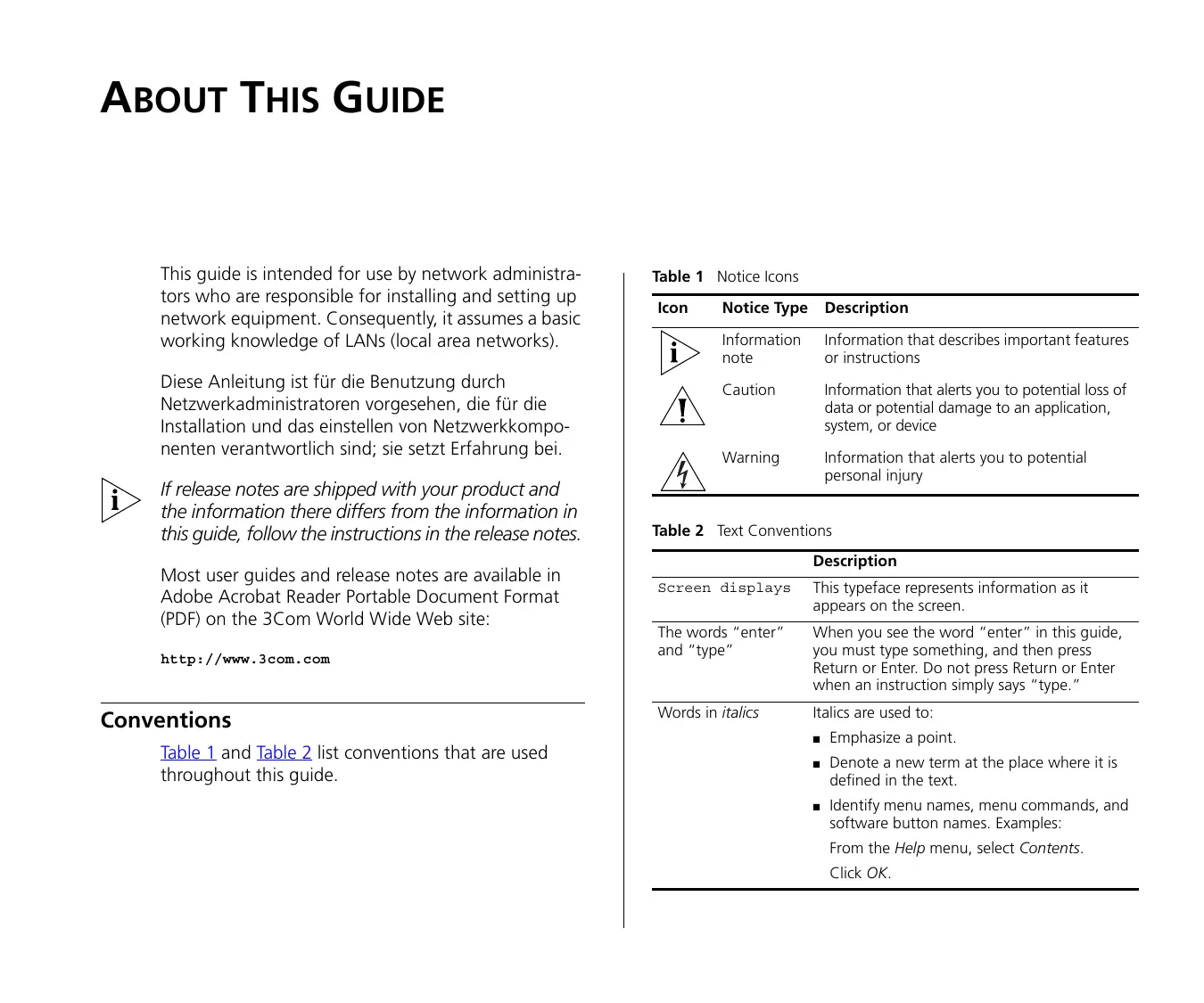
Conventions
Table 1 and Table 2 list conventions that are used throughout this guide.
Table 1 Notice Icons
| Icon | Notice Type | Description |
| i | Information note | Information that describes important features or instructions |
| ! | Caution | Information that alerts you to potential loss of data or potential damage to an application, system, or device |
| Warning | Information that alerts you to potential personal injury |
Table 2 Text Conventions
| Description | |
| Screen displays | This typeface represents information as it appears on the screen. |
| The words "enter" and "type" | When you see the word "enter" in this guide, you must type something, and then press Return or Enter. Do not press Return or Enter when an instruction simply says "type." |
| Words in italics | Italics are used to: ■ Emphasize a point. ■ Denote a new term at the place where it is defined in the text. ■ Identify menu names, menu commands, and software button names. Examples: From the Help menu, select Contents. Click OK. |
Related Documentation
In addition to this guide, each 3Com Baseline Switch 2226 Plus documentation set includes the following:
- Online Help - Accessible from the Web interface, provides information that helps you perform tasks using the Web interface.
- Release Notes - Provide information about the current software release, including new features, modifications, and known problems.
Documentation Comments
Your suggestions are very important to us. They will help make our documentation more useful to you. Please e-mail comments about this document to 3Com at:
pddtechpubscomments@3com.com
Please include the following information when contacting us:
Document title
Document part number (on the title page)
Page number (if appropriate)
Example:
3Com Baseline Switch 2226 Plus User Guide
Part number: DUA16475B-SAAA01
Page 25

Please note that we can only respond to comments and questions about 3Com product documentation at this e-mail address. Questions related to technical support or sales should be directed in the first instance to your network supplier.
1 INTRODUCING THE BASELINE SWITCH
This chapter provides an overview of the features and capabilities of the 3Com® Baseline Switch 2226 Plus. It also identifies the contents of the Switch package and helps you get to know the physical features of the device.
Overview of the Baseline Switch 2226 Plus
The 3Com Baseline Switch 2226 Plus is a versatile, easy-to-use configurable Switch. It is ideal for users who want the high-speed performance of 10/100 switching with the added functionality of Gigabit links, but do not need sophisticated management capabilities.
The Switch is shipped ready for use. No configuration is necessary, unless you want to configure advanced features such as VLAN support, link aggregation, and traffic prioritization.
Features and Capabilities
The Switch has 24 shielded RJ-45, 10/100 Mbps auto-negotiating ports and two dual purpose 10/100/1000BASE-T ports that operate in conjunction with two Small Form Factor Pluggable (SFP) transceiver slots on the front panel for easy, flexible connection to fiber-based Gigabit media.
While there are four physical Gigabit ports, only a maximum of two can be operational at any given time.
Autosensing of MDI/MDIX Connections
All ports on the Switch can autosense both medium dependent interface (MDI) and medium dependent interface crossover (MDIX) connections. This allows you to connect network devices to each port using either a normal straight-through TP (twisted pair) cable or a 'crossover' TP cable.
Any port can therefore be used to connect to another switch port, server, or workstation without additional configuration.
Autonegotiating 10/100 Mbps Ports
Each 10/100 Mbps port automatically determines the speed and duplex mode of the connected equipment and provides a suitable switched connection. The 1000BASE-T ports also support automatic 10/100/1000 Mbps speed detection.
10/100 Mbps connections on these 1000BASE-T ports can operate in either half-duplex or full-duplex mode. 1000 Mbps connections, on the other hand, only operate in full duplex mode.
SFP Ports
The two SFP ports support fiber Gigabit Ethernet short-wave (SX) and long-wave (LX) SFP transceivers in any combination. This offers you the flexibility of using SFP transceivers to provide connectivity between the Switch and a 1000 Mbps core network. When an SFP port is in operation, the corresponding 10/100/1000BASE-T port is disabled.
Traffic Prioritization
The Switch supports two types of traffic prioritization:
Prioritization of IP phone traffic
Priority Queuing
Prioritization of IP Phone Traffic
The Switch can recognize when an NBX phone is connected to any of the ports 1 to 24. The Switch will automatically detect the NBX phone when the phone starts up, and will ensure that traffic to and from the phone is given the highest priority.

To ensure that the NBX phone is recognized by the Switch during its initialization, do not connect any data source through the phone until the phone has finished its startup sequence.
Once the phone is available for use, any data source (for example, a computer) can then be connected to the phone's pass-through port. This only applies if you use a single wall jack for your network connection and use the pass-through LAN port on the NBX phone.
Traffic Priority Queuing
The Switch also offers priority queuing. It examines each packet that it receives to determine if it is priority-encoded. If a packet is priority-encoded, the Switch reads the priority level and determines whether the packet should be directed through the normal or high priority channel. This feature is useful, for example, during periods of excessive network load, when one type of traffic may require priority over another. The Switch is configured to comply with 802.1p, VLAN tagged frames.
Traffic prioritization ensures that high priority data is forwarded through the Switch without being delayed by lower priority data. It differentiates traffic into classes and prioritizes those classes automatically.
Traffic prioritization uses multiple traffic queues that are present in the hardware of the Switch to ensure that high priority traffic is forwarded on a different queue from lower priority traffic, and is given preference over that traffic. This ensures that time-sensitive traffic gets the highest level of service.
The 802.1D standard specifies eight distinct levels of priority (0 to 7), each of which relates to a particular type of traffic. The priority levels and their traffic types are shown in Table 3.
Table 3 Priority Levels for Traffic Types
| Priority Level | Traffic Type |
| 0 | Best effort |
| 1 | Background |
| 2 | Standard (spare) |
| 3 | Excellent effort (business critical) |
| 4 | Controlled load (streaming multimedia) |
| 5 | Video (interactive media), less than 100 milliseconds latency and jitter |
| 6 | Voice (interactive voice), less than 10 milliseconds latency and jitter |
| 7 | Network control reserved traffic |

The traffic prioritization feature supported by the Switch is compatible with the relevant sections of the IEEE 802.1D standard (incorporating IEEE 802.1p).
Physical Features
Figure 1 shows the front and rear panels of the Switch. The numbers in this diagram refer to numbered sections in "Front Panel" on page 9 and "Rear Panel" on page 12.
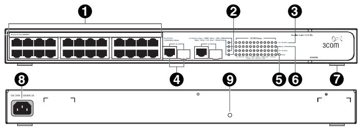
Figure 1 Front and Rear Panels
Front Panel
The front panel of the Switch contains a series of indicator lights (LEDs) that help describe the state of various networking and connection operations.
(1) 24 RJ-45 Ports

WARNING: RJ-45 Ports. These are shielded RJ-45 data sockets. They cannot be used as standard traditional telephone sockets, or to connect the unit to a traditional PBX or public telephone network. Only connect RJ-45 data connectors, network telephony systems, or network telephones to these sockets.
Either shielded or unshielded data cables with shielded or unshielded jacks can be connected to these data sockets.

The Switch has 24 10/100 Mbps autonegotiating ports. Each port supports automatic MDI/MDI-X detection and can be connected to either a 10BASE-T, or a 100BASE-TX device.
Ports 1 to 24 are autonegotiating — their speed and duplex mode (half-duplex or full-duplex) are automat-
ically determined by the capabilities of the connected device.

CAUTION: The Switch supports full-duplex autonegotiation. If the connected device does not support autonegotiation, the Switch will operate in half-duplex mode (even if the attached device is operating in full-duplex mode).
In such a configuration, you may notice some degradation of network performance. 3Com recommends that you use devices that are capable of autonegotiation (and that you ensure that autonegotiation is enabled, if it is a configurable option). (see "Troubleshooting" on page 43).
(2) Module Active LEDs
The Module Active LEDs show the status of any SFP modules that are installed.
| Status | Meaning |
| Green | Fiber SFP is inserted in the slot |
| Off | No fiber SFP is inserted in the slot |
(3) Link/Activity LEDs
The Link/Activity LEDs show the link status of ports and the speed of connected devices.
| Status | Meaning |
| Green | The link is operating at 1000 Mbps |
| Yellow | The link is operating at 10 or 100 Mbps |
| Flashing Green | Packets are being received or transmit-ted on the port at 1000 Mbps |
| Flashing Yellow | Packets are being received or transmitted on the port at 10 or 100 Mbps |
| Flashing Yellow to Green | Port disabled or link loopback error |
| Off | The link has not been established, either nothing is connected to the port, or there is a problem: ■ Verify that the attached device is powered on ■ Verify that the cable or fiber is the correct type and is not faulty ■ For fiber connections, ensure that the receive (RX) and transmit (TX) cable connectors are not swapped If these checks do not identify the cause of the problem, it may be that the unit or the device connected to the port is faulty. Contact your 3Com network supplier for further advice. |
(4) 10/100/1000BASE-T/SFP Ports
Ports 25 and 26 are combination Gigabit RJ-45 ports with shared Small Form Factor Pluggable (SFP) transceiver slots. If an SFP transceiver (purchased separately) is installed in a slot and is active, the associated RJ-45 port of the same number is disabled.
The 1000BASE-T RJ-45 ports support automatic MDI/MDI-X operation, so you can use straight-through or crossover cables for all network connections to workstations or servers, or to other switches or hubs.
The two SFP ports support fiber Gigabit Ethernet short-wave (SX) and long-wave (LX) SFP transceivers in any combination. This offers you the flexibility of using SFP transceivers to provide connectivity between the Switch and remote 1000 Mbps workgroups or to create a high-capacity aggregated link backbone connection.

SFP ports are numbered 25 and 26 on the Switch. When an SFP port is active, it has priority over the 10/100/1000 port of the same number. The corresponding 10/100/1000 port is disabled when an SFP transceiver is plugged in.
(5) Power LED
The Power LED shows the power status of the Switch.
| Status | Meaning |
| Green | The unit is powered on and ready for use |
| Off | The unit is not receiving power: ■ Verify that the power cord is connected cor-rectly ■ If the unit still does not operate, contact your 3Com network supplier |
| Flashing Green | ■ Power-on self-test is in progress |
| Yellow | ■ Power-on self-test or loopback test failed. Switch is in fail-safe mode. |
(6) Duplex LEDs
The second and fourth (bottom) row of Status LEDs, which are colored yellow, show the duplex status of the related ports.
| Status | Meaning |
| Off | No link, link is not yet negotiated, or the port is operating in half-duplex mode |
| Yellow | The port is operating in full-duplex mode |
(7) Self-Adhesive Pads
The unit is supplied with four self-adhesive rubber pads.

Do not apply the pads if you intend to rack-mount the unit.
If the unit is to be part of a free-standing stack, apply the pads to each marked corner area on the underside of the unit. Place the unit on top of the lower unit, ensuring that the pads locate with the recesses of the lower unit.
Rear Panel
(8) Power Supply
The Switch automatically adjusts to the supply voltage. Only use the power cord that is supplied with the unit.
(9)Recovery Button
Use the Recovery button on the rear panel to reset the Switch to its factory defaults. For more informa
tion, refer to “Resetting to Factory Defaults” on page 43.
Package Contents
The 3Com Baseline Switch 2226 Plus package includes the following items:
One 3Com Baseline Switch 2226 Plus unit
One power cord
Four standard height, self-adhesive rubber pads
One mounting kit
One CD-ROM, which contains this User Guide and the 3Com Discovery application
One warranty flyer
Before installing and using the Switch, verify that your Switch package has all these items. If any of the above items are damaged or missing, contact your 3Com network supplier immediately.
2 INSTALLING THE SWITCH
This chapter contains information that you need to install and set up the Switch. It covers the following topics:
Positioning the Switch
Rack-Mounting or Free-Standing.
Supplying Power to the Switch
- Connecting a Network Device
- Connecting a Network Device
Performing Spot Checks
Before You Begin

WARNING: Safety Information. Before installing or removing any components from the Switch or carrying out any maintenance procedures, read the safety information provided in Appendix B of this guide.

Positioning the Switch
The Switch is suitable for use in an office environment where it can be free-standing or mounted in a standard 19-inch equipment rack.
Alternatively, the Switch can be rack-mounted in a wiring closet or equipment room. A mounting kit, containing two mounting brackets and four screws, is supplied with the Switch.
When deciding where to position the Switch, ensure that:
It is accessible and cables can be connected easily.
- Cabling is away from sources of electrical noise. These include lift shafts, microwave ovens, and air conditioning units. Electromagnetic fields can interfere with the signals on copper cabling and introduce errors, therefore slowing down your network.
Water or moisture cannot enter the case of the unit.
Airflow around the unit and through the vents in the side of the case is not restricted (3Com recommends that you provide a minimum of 25 ~mm or 1 in. clearance).
The air is as free of dust as possible.
- Temperature operating limits are not likely to be exceeded. It is recommended that the unit be installed in a clean, air-conditioned environment.

It is always good practice to wear an anti-static wrist strap when installing network equipment, connected to a ground point. If one is not available, try to keep in contact with a grounded rack and avoid touching the unit's ports and connectors, if possible. Static discharge can cause reliability problems in your equipment.
Rack-Mounting or Free-Standing
The unit can be mounted in a 19-inch equipment rack using the supplied mounting kit, (see "Using the Mounting Kit" on page 15), or it can be free-standing. Do not place objects on top of the unit or stack.

CAUTION: If installing the Switch in a free-standing stack of different size Baseline or SuperStack® 3 units, the smaller units must be installed above the larger ones. Do not have a free-standing stack of more than six units.
Using the Mounting Kit
The Switch is supplied with two mounting brackets and four screws. These are used for rack mounting the unit. When mounting the unit, take note of the guidelines given in "Positioning the Switch" on page 13.
The Switch is 1U (1.75 in.) high and will fit in a standard 19-inch rack.

CAUTION: Before continuing, disconnect all cables from the unit. Remove the self-adhesive pads from the underside of unit, if already fitted.
To rack-mount the Switch:
1 Place the unit the right way up on a hard, flat surface with the front facing towards you.
2 Locate a mounting bracket over the mounting holes on one side of the unit.
3 Insert the two screws supplied in the mounting kit and fully tighten with a suitable screwdriver.
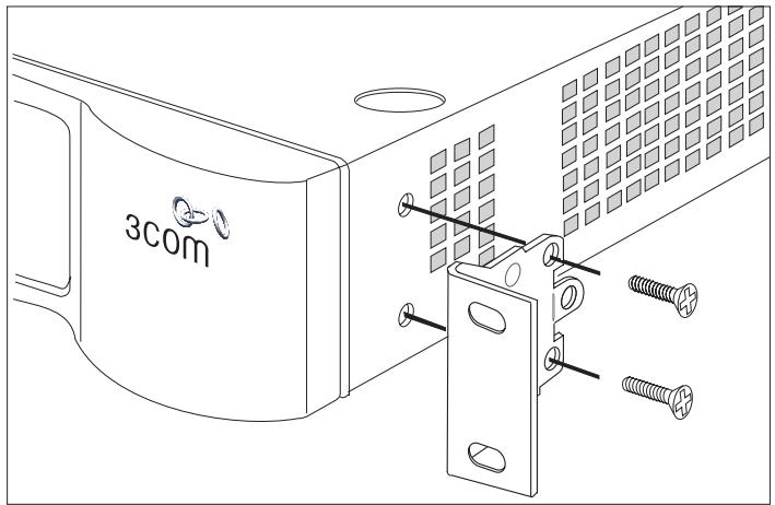
Figure 2 Inserting the Screws
4 Repeat the two previous steps for the other side of the unit.
5 Insert the unit into the 19-inch rack and secure with suitable screws (not provided). Ensure that the ventilation holes are not obstructed.
6 Reconnect the network cables.
Placing Units On Top of Each Other
If the Switch units are free-standing, up to four units can be placed one on top of the other. If you are mixing a variety of Baseline and SuperStack units, the smaller units must be positioned at the top.
If you are placing Switch units one on top of the other, you must use the self-adhesive rubber pads supplied. Apply the pads to the underside of each Switch, sticking one in the marked area at each corner. Place the Switch units on top of each other, ensuring that the pads of the upper unit line up with the recesses of the lower unit.
Supplying Power to the Switch
Power problems can be the cause of serious failures and downtime in your network. Ensure that the power input to your system is clean and free from sags and surges to avoid unforeseen network outages. 3Com recommends that you install power conditioning, especially in areas prone to black outs, power dips and electrical storms.
The unit is intended to be grounded. Ensure it is connected to earth ground during normal use. Installing proper grounding helps to avoid damage from lightning and power surges.

Before powering on the Switch, verify that network cables and the power cable are securely connected.

CAUTION: The Switch has no ON/OFF switch; the only method of connecting or disconnecting main power is by connecting or disconnecting the power cord.
To power on the Switch:
1 Plug the power cord into the power socket on the rear panel of the Switch. Refer to " (8) Power Supply" on page 12 for more information.
2 Plug the other end of the power cord into a power outlet.
When the Switch is powered on, the Power LED lights up. If the Power LED does not light up, refer to “(5) Power LED” on page 11 for more information.
Checking for Correct Operation
After you power on the Switch, it automatically performs a power-on self-test (POST). During POST, the Power LED on the front panel of the Switch flashes green.
When POST is complete, the Power LED turns green. If the Power LED turns yellow after POST, it means that POST failed and the Switch has entered fail-safe mode.
Table 4 summarizes the possible colors for the Power LED after POST.
Table 4 Possible Power LED Colors After POST
| Color | State |
| Green | The unit is powered on and ready for use |
| Yellow | Power-on self-test or loopback test failed. The Switch is in fail-safe mode. This can happen if a ports or ports fail when the Switch is powered on. |
| Off | The unit is not receiving power: ■ Verify that the power cord is connected correctly, and then try powering on the Switch again ■ If the Switch still does not operate, contact your 3Com network supplier |
If POST fails, try the following:
Power off the Switch, and then power it on again. Check the Power LED and see if POST was successfully completed.
Reset the Switch. See "Resetting to Factory Defaults" on page 43.

CAUTION: Resetting the Switch to its factory defaults erases all your settings. You will need to reconfigure the Switch after you reset it.
If these do not resolve the issue:
- Check the 3Com Knowledgebase for a solution. To visit the 3Com Knowledgebase Web site, start your Web browser, and then enter
http://knowledgebase.3com.com.
- Contact your 3Com network supplier for assistance.
Connecting a Network Device
To connect a network device to the Switch, use Category 5 unshielded or shielded (screened) 100 Ohm TP cables (or Category 3 cables for 10 Mbps connections).
For optimal connections, ensure that the cable length for each connection is not longer than 100m (328 ft).
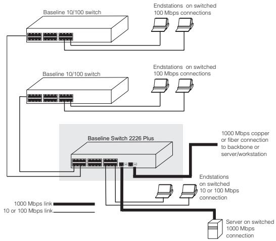
Figure 3 Connecting Devices to the Switch
To connect a device to the Switch:
1 Connect one end of the cable to an RJ-45 port on the Switch.
2 Connect the other end to the appropriate RJ-45 port on the connecting device.
For 1000BASE-T operation, 3Com recommends using Category 5e or 6 cables.
Using SFP Transceivers
The following sections describe how to insert and remove an SFP transceiver from an SFP slot.

SFP transceivers are hot-insertable and hot-swappable. You can remove them from and insert them into any SFP port without having to power off the Switch.
Approved SFP Transceivers
The following list of approved SFP transceivers is correct at the time of publication:
3CSFP91 SFP (SX)
3CSFP92 SFP (LX)
To access the latest list of approved SFP transceivers for the Switch on the 3Com Corporation World Wide Web site, enter this URL into your Internet browser:
http://www.3com.com

3Com recommends using 3Com SFPs on the Switch. If you insert an SFP transceiver that is not supported, the Switch will not recognize it.
Inserting an SFP Transceiver
To be recognized as valid, the SFP transceiver must be one of the following:
1000BASE-SX SFP transceiver - Use this transceiver to connect the Switch directly to a multimedia fiber-optic cable.
1000BASE-LX SFP transceiver - Use this transceiver to connect the Switch directly to a single-mode fiber-optic cable or to multimode fiber using a conditioned launch cable.

If the SFP transceiver is faulty, it will not operate within the Switch. See "Troubleshooting" on page 43.
To insert an SFP transceiver:
1 Hold the transceiver so that the fiber connector is toward you and the product label is visible, as shown
in Figure 4. Ensure the wire release lever is closed (in the upright position).
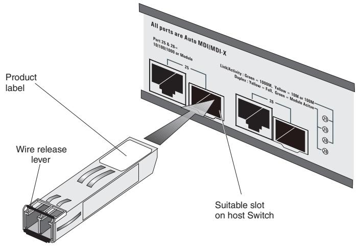
Figure 4 Inserting the SFP Transceiver
2 Gently slide the transceiver into the SFP slot until it clicks into place.

CAUTION: SFP transceivers are keyed and can be properly inserted only one way. If the transceiver does not click when you insert it, remove it, turn it over, and then re-insert it.
3 Remove the plastic protective cover, if fitted.
4 Connect the fiber cable.
5 The transceiver connects to the network using a duplex LC connector. Attach a male duplex LC connector on the network cable into the duplex LC connector on the transceiver.
6 Connect the other end of the cable to a device fitted with an appropriate Gigabit Ethernet connection.
7 Check the Module Active LEDs on the front of the Switch to ensure that it is operating correctly.
Removing an SFP Transceiver
Removing an SFP transceiver does not require powering off the Switch.
To remove an SFP transceiver:
1 Disconnect the cable from the transceiver.
2 Move the wire release lever downwards until it is pointing toward you.
3 Pull the wire release lever toward you to release the catch mechanism.
The SFP transceiver should slide out easily.
Performing Spot Checks
At frequent intervals, you should visually check the Switch. Regular checks can give you an early warning of a possible failure; any problems can then be attended to when there will be least effect on users.
3Com recommends periodically checking the items listed in Table 5.
Table 5 Items to Check
| Item | Verify That |
| Cabling | All external cabling connections are secure and that no cables are pulled taut |
| Cooling fan | Where possible, check that the cooling fan is operating by listening to the unit. The fan is fitted on the right side of the unit (when viewed from the front). |
If you experience any problems operating the Switch, refer to "Troubleshooting" starting on page 43.
3 CONNECTING TO THE WEB INTERFACE
The Switch has a built-in Web interface that you can use to set the admin password, change the IP address that is assigned to the Switch, and configure its advanced settings.

If you only want the Switch to function as a basic layer 2 switch, you do not need to access the Web interface and configure the Switch.
This chapter provides information on how the gain access to the Web interface using the Discovery application. It also introduces the menu items and buttons that are available on the Web interface.
The following topics are covered:
- Requirements for Accessing the Web Interface
Running the Discovery Application - Logging On to the Web Interface
Navigating the Web Interface
Requirements for Accessing the Web Interface
To connect to the Web interface, you need the following:
The Discovery application, which is included on 3Com Baseline Switch 2226 Plus CD-ROM that is supplied with your Switch
A computer that is connected to the Switch and that has a Web browser
Running the Discovery Application
The 3Com Baseline Switch 2226 Plus CD-ROM contains, among others, the Discovery application.
To use Discovery to connect to the Web interface, do the following:
1 On a computer that is connected to the Switch, insert the CD-ROM into its CD drive.
Discovery should start automatically. If it does not start automatically, go to the \Discovery folder on the CD-ROM, and then double-click discovery.exe.
The Welcome screen of Discovery appears.
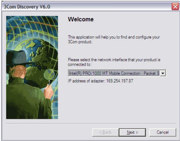
Figure 5 Welcome Screen of Discovery
2 If the computer has multiple network adapters, select the adapter that connects the computer to the Switch, and then click Next.
If the computer has only one adapter, click Next.
Discovery searches the network for 3Com devices. When detection is complete, the Discovered Devices screen displays detected network devices.
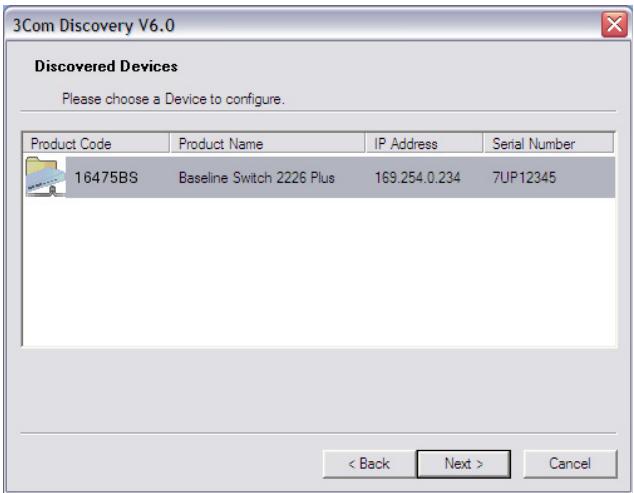
Figure 6 Discovered Devices Screen
3 On the Discovered Devices screen, click Baseline Switch 2226 Plus, and then click Next. The Completing the 3Com Discovery Application screen appears.
4 Click Finish.
The Web interface loads in your Web browser.
Logging On to the Web Interface
After the Web interface loads in your Web browser, the first page that appears is the logon screen. On this screen, you need to enter the administration user name and password to gain access to the Web interface.
The logon screen also displays the IP address that the Switch is currently using.
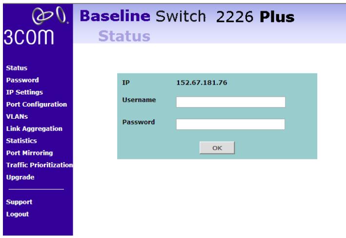
Figure 7 Logon Screen
To log on to the Web interface:
1 InUsername,typeadmin.
2 Leave the Password field blank.
3 Click OK.
Navigating the Web Interface
The Web interface has been designed to enable you to easily perform advanced configuration tasks and view information about the Switch.
Menu
The menu is located on the left side of the Web interface. When you click an item on the menu, the
related screen appears in the main part of the interface.
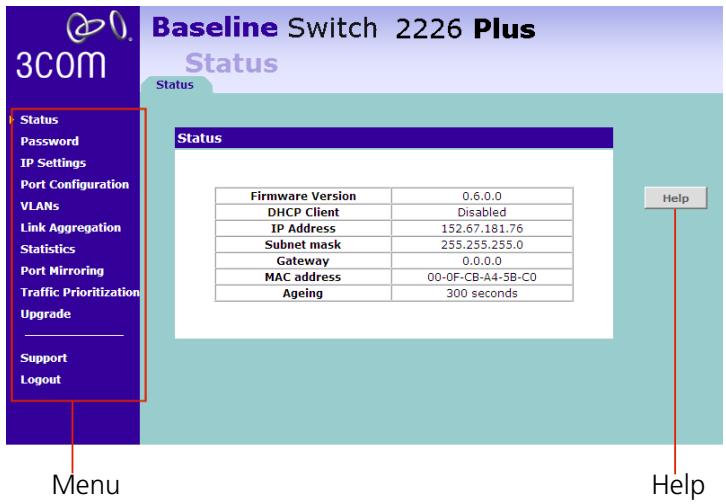
Figure 8 Switch Screen Layout
Table 6 lists the available items on the menu.
Table 6 Available Menu Items
| Menu Item | Description |
| Status | Provides a summary of the Switch's basic settings and versions of current components |
| Password | Allows you to change the administrator password |
| IP Settings | Allows you to configure the IP address settings of the Switch |
| Port Configuration | Allows you to configure the Switch's port settings |
| VLANs | Allows you to create VLAN groups, add port members, and specify how VLAN tagging is used |
| Link Aggregation | Allows you to set up and maintain trunk membership for port groups |
| Statistics | Displays the number of packets received and transmitted from each individual port |
| Traffic Monitoring | Allows you to perform port traffic monitoring on the Switch. To monitor a port, you will also need a network analyzer. |
| Traffic Prioritization | Allows you to configure traffic prioritization for IP phones that are connected to the Switch |
| Upgrade | Allows you to upgrade the firmware on the Switch. Before you can perform an upgrade, you first need to download firmware updates from the 3Com Web site. |
| Support | Displays 3Com contact information and describes how to use the online help system |
| Log Out | Allows you to securely log off the Web interface |
Buttons
Depending on the screen that is currently displayed, the following buttons may appear:
- Apply - Click to save and apply any changes that you have made
-
Cancel - Click to discard any unsaved changes
-
Help - Click to display the context-sensitive help information for the screen that is currently displayed. The help pages provide information on the tasks that you can perform on each screen.
Accessing the Interface Without Using Discovery
The Discovery application works by automatically detecting the IP address that is assigned to the Switch, and then using that address to connect to the Web interface. If you know the Switch's IP address, you can access the Web interface without using Discovery.
This section describes how to access the interface directly, without using Discovery.

If you do not configure the Switch's IP address settings, it will perform auto IP configuration to assign an IP address to itself. For more information, refer to "Automatic IP Configuration" on page 29.
To determine the IP address that the Switch will assign to itself during auto IP configuration, check the sticker on the base of the Switch. This sticker contains the MAC address and default IP address of the Switch.
DHCP Assigned IP Address
If you set the IP address mode to DHCP, check the DHCP server for the IP address that is assigned to the Switch, and then use that IP address to access the Web interface.
For example, if the DHCP server assigned the IP address 192.168.0.123 to the Switch, start your Web browser, and then type http://192.168.0.123.
Manually Assigned (Static) IP Address
If you assigned a static IP address to the Switch, you need to use that IP address to access the Web interface the next time you want to configure the Switch.
For example, if you assigned the Switch the IP address 192.168.0.123, start your Web browser, and then type http://192.168.0.123.
4
CONFIGURING THE SWITCH
This chapter provides information on how to configure the Switch's advanced features. Topics include:
Changing the Admin Password
Modifying the IP Address Settings
- Configuring Port Settings
- Configuring VLANs
- Configuring Link Aggregation
Monitoring Traffic
Setting the Traffic Priority
Upgrading the Firmware
Configuration Overview
The Switch is shipped ready for use. If you only want the Switch to function as a basic layer 2 switch, you do not need to access the Web interface and configure the Switch.
You only need to access the Web interface if you want to:
- Set the administration password to the Web interface
■ Assign an IP address to the Switch - Configure the Switch's advanced features
Upgrade the firmware
Viewing Status Information
The Status screen, which automatically loads after you log on to the Web interface, provides a snapshot of the Switch's basic settings and versions of current components.
Figure 9 Status Screen
Status
Table 7 lists the information that you can view on the Status screen.
| Firmware Version | 1.1.0.3 |
| DHCP Client | Disable |
| IP Address | 152.67.181.106 |
| Subnet mask | 255.255.255.0 |
| Gateway | 192.168.0.1 |
| MAC address | 00-0F-CB-A4-56-40 |
| Ageing | 300 seconds |
Table 7 Items on the Status Screen
| Item | Description |
| Firmware Version | Displays the version of the firmware that is currently installed on the Switch |
| DHCP Client | Shows Enable if the Switch obtained its IP address from a DHCP server on the network. Otherwise, this field shows Disable. |
| IP Address | Displays the IP address that is assigned to the Switch, whether it was obtained from a DHCP server or you manually set it |
| Subnet Mask | Displays the subnet mask that is assigned to the Switch |
| Gateway | Displays the gateway address (if any) that is assigned to the Switch |
| MAC Address | Displays the MAC or physical address of the Switch |
| ARL Ageing | Displays the number of seconds before the Switch removes dynamically learned addresses from its MAC address table. This is set to 300 seconds and is not configurable. |
If you request for technical assistance from 3Com Support, you may be asked to print out the information on this screen.
Changing the Admin Password
To prevent unauthorized users from accessing the Web interface and modifying the Switch's settings, the interface is password-protected.
The default admin account settings are:
■ User name - admin
- Password - blank (no password)
To ensure that unauthorized users do not access the Web interface, 3Com recommends that you set an admin password when you first configure the Switch.

Figure 10 Change Administration Password Screen
Even if you do not intend to actively manage the switch, 3Com recommends that you change the password to prevent unauthorized access to your network.
Change Administration Password
Old Password
New Password
Confirm Password
Note: Password is case sensitive.
Help
Apply
Cancel
To set the admin password:
1 On the menu, click Password. The Change Administration Password screen appears.
2 In Old Password, type your current password. By default, the Switch does not have any password. If this is your first time to access this screen or if you
have not previously set a password, leave this field blank.
3 In New Password, type the password that you want to set.
4 In Confirm Password, retype the password you typed in step 3 to confirm.

The password is case-sensitive.
5 Click Apply.
If you want to modify the admin password later on, follow the same procedure.

If you forget the administration password after you set it, refer to "Forgotten Password" on page 44 for information on how to regain access to the Web interface.
Modifying the IP Address Settings
To enable devices on the network to communicate with the Switch, you need to assign an IP address to it — either by DHCP or by manually assigning a static IP address.
By default, the Switch performs automatic IP configuration and assigns an IP address to itself. This is necessary for the Discovery application to be able to connect to the Web interface.
Automatic IP Configuration
When you power on the Switch for the first time, it automatically uses the default IP address 169.254.x.y, where x and y are the last two bytes of its MAC address.

To determine the exact IP address that the Switch assigns to itself during auto IP configuration, check the sticker on the base of the Switch. This sticker contains the MAC address and default IP address of the Switch.
To detect its IP information using the automatic configuration process, the Switch goes through the following sequence of steps:
1 The Switch tries to configure itself with the default IP address 169.254.x.y, where x and y are converted from the last two bytes of its MAC address.
For example, if the MAC address were 08004E000102, the IP address would be 169.254.1.2. This address is used if the Switch is operating in a standalone mode, or no other switches on the network have this IP address.
The Switch also assigns the subnet mask 255.255.0.0 (default class B mask) to itself.
2 If this default IP address is already in use on the network, then the Switch detects this, and increments the last byte of the MAC address by one to generate its IP address.
The IP address would therefore become 169.254.1.3.
3 The Switch repeats step 2 until an unused IP address is found.

3Com recommends using automatic IP configuration only for the initial setup. Once you gain access to the console, you should assign an IP address to the Switch (either by using DHCP or assigning a static IP address) to ensure successful communication between the Switch and other network devices.
Setting the IP Address
To set the IP address for the Switch:
1 Click IP Settings on the menu. The IP Settings screen appears.
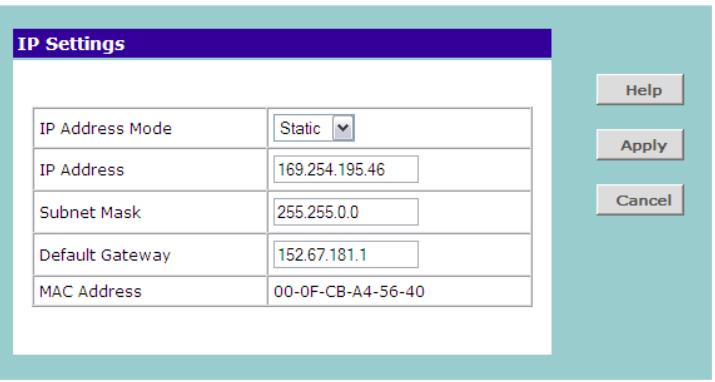
Figure 11 IP Settings Screen
2 Configure the Switch's IP settings. Available options are listed in Table 8.
Table 8 IP Setting Options
| Option | Description |
| IP Address Mode | Specify how the Switch will get its IP address. Available options include: ■ DHCP – Select this option if you have a DHCP server on the network and you want the Switch to automatically obtain an IP address from it ■ Static – Select this option if you want to manually assign an IP address to the Switch |
| IP Address | Specify an IP address that you want to assign to the Switch. This option is only available if IP Address Mode is set to Static. The IP address that is assigned to the Switch also becomes the IP address for VLAN 1. |
| Subnet Mask | Specify a subnet mask address that you want to assign to the Switch. This option is only available if IP Address Mode is set to Static. The default subnet mask is 255.255.0.0. |
| Default Gateway | Specify the IP address of the gateway router between this Switch and management stations on other network segments. This option is only available if IP Address Mode is set to Static. |
| MAC Address | Read-only field that displays the Switch's MAC or physical address |
3 After you configure the Switch's IP address settings, click Apply to save your changes.
Configuring Port Settings
Using the Web interface, you can configure the speed/duplex and flow control settings of each port. You can also shut down or disable ports from the Web interface.
Viewing Port Settings
To view the current port settings, click Port Configuration on the menu. The Port Configuration screen appears (see Figure 12), displaying the status of all ports and a summary of their current settings.
Figure 12 Port Configuration Screen
| Port Configuration | ||||||
| Port | Link Status | Speed Duplex | Flow Control | Port | Link Status | Speed Duplex Flow Control |
| 01 | Up | 100Mbps Full | Enable | 16 | Down | -- |
| 02 | Down | -- | -- | 17 | Down | -- |
| 03 | Down | -- | -- | 18 | Down | -- |
| 04 | Down | -- | -- | 19 | Down | -- |
| 05 | Down | -- | -- | 20 | Down | -- |
| 06 | Down | -- | -- | 21 | Down | -- |
| 07 | Down | -- | -- | 22 | Down | -- |
| 08 | Down | -- | -- | 23 | Down | -- |
| 09 | Down | -- | -- | 24 | Down | -- |
| 10 | Down | -- | -- | 25 | Down | -- |
| 11 | Down | -- | -- | 26 | Down | -- |
| 12 | Down | -- | -- | AL1 | Down | -- |
| 13 | Up | 100Mbps Full | Enable | AL2 | Down | -- |
| 14 | Down | -- | -- | AL3 | Down | -- |
| 15 | Down | -- | -- | AL4 | Down | -- |
Table 9 describes the information that appears on the Port Configuration screen.
Table 9 Port Configuration Summary Screen
| Item | Description |
| Port | The physical number of the port that corresponds to the numbering of the ports on the front of the unit. Note that ports 25 and 26 are dual function ports. When the Small Form Factor Pluggable (SFP) transceiver ports are not in use, the number refers to the RJ-45 port. When an SFP module is inserted, the port number refers to this port, even if a fiber cable is not inserted. |
| To configure the settings of a particular port, click the port number. | |
| The items AL1 to AL4 refer to trunk groups. Use these to configure the settings of a trunk's member ports. See “Configuring Trunk Settings” on page 38. | |
| Link Status | Indicates whether the port is currently active (up) or not (down) |
| Speed/Duplex | If the link is up, indicates the speed and duplex settings of the port |
| Flow Control | If the link is up, indicates whether flow control is enabled on the port |
Default Port Settings
If you do not configure the Switch's port settings, the ports will use the following default settings:
All ports are enabled
Autonegotiation is enabled
Flow control is enabled
All ports are set to priority zero
Changing a Port's Settings

If a port is a member of an aggregated link (or trunk), you will not be able to configure its individual port settings. All member ports of an aggregated link will have the same settings, and you can configure these by clicking the AL link on the Port Configuration screen. See "Configuring Trunk Settings" on page 38.
To change the settings of a port:
1 Under the Port column of the Port Configuration screen, click the port number that you want to configure. The Port Settings screen appears, as shown in Figure 13.
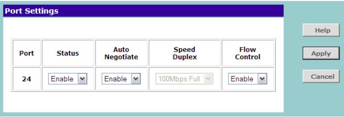
Figure 13 Port Settings Screen
2 Configure the port settings. Available options are listed in Table 10.
Table 10 Port Setting Options
| Option | Description |
| Status | ■ Enable - Activates the port■ Disable - Shuts down or disables the portBy default, admin setting is set to enable. |
| Auto Negotiate | Autonegotiation, which is enabled by default, sets the optimum combination of speed and duplex that can be supported by both ends of the link. Available options for autonegotiation include:■ Enable - Enables autonegotiation for the port. If autonegotiation is enabled, options for Speed Duplex are unavailable.■ Disable - Disables autonegotiation for the port. If autonegotiation is disabled, you need to set the speed and duplex mode in Speed Duplex. |
| Speed Duplex | Sets the preferred speed and duplex mode for the port. This option is only available when autonegotiation for the port is disabled. Available speed and duplex modes include: ■ 10Mbps Half ■ 10Mbps Full ■ 100Mbps Half ■ 100Mbps Full (for ports 25 and 26 only) - See “Speed/Duplex for 1000 Mbps Connections” on page 33. |
| Flow Control | When enabled, controls packet flow so that a sending device does not transmit more packets than a receiving device can process. If flow control is disabled, packets may be dropped under certain periods of high traffic loads. By default, flow control is enabled. |
3 Click Apply to save your settings.
To configure another port, click Port Configuration on the menu again, and then click the port number that you want to configure.
Speed/Duplex for 1000 Mbps Connections
You cannot preset the speed to 1000Mbps. To run a port at 1000Mbps, you must enable autonegotiation for the port. When autonegotiation is enabled, the Switch will automatically connect at 1000Mbps, providing the connected device also supports this speed.
1000Mbps connections are always full-duplex. Half-duplex connections are only available for 10Mbps and 100Mbps settings.

CAUTION: Before manually setting a port to full-duplex, verify that the device connected to the port is also manually set to the same speed and duplex setting. If connecting link partners are left to autonegotiate for a link manually set on this switch to full-duplex, they will always negotiate to half-duplex, resulting in a duplex mismatch. This can result in a significant reduction in network performance. If you are unsure of how to configure the speed/duplex setting, simply enable autonegotiation for the port.

You cannot modify the speed/duplex settings of ports that are members of a trunk or aggregated link.

Supported SFP transceivers only operate at 1000Mbps full-duplex. Inserting an SFP transceiver into a gigabit port disables the corresponding RJ-45 port, even if no fiber cable is inserted.
Configuring VLANs
You can use the Switch to create VLANs to organize any group of ports into separate broadcast domains. VLANs confine broadcast traffic to the originating group and help eliminate broadcast storms in large networks. This also provides for a more secure and cleaner network environment.
You can create up to 64 VLANs, add specific ports to a chosen VLAN (so that the port can only communicate with other ports on the VLAN), or configure a port make it a member of all VLANs.
Communication between different VLANs can only take place if they are all connected to a router or layer 3 switch.
Creating a VLAN
Use the VLANs page to create VLANs on the Switch. To propagate information about VLAN groups used on this Switch to external devices, you must specify a VLAN ID for each VLAN.
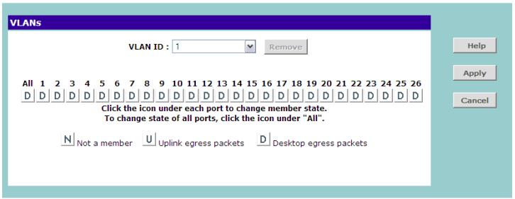
Figure 14 VLANs Screen
Ports belonging to a VLAN must be set to either U (uplink) or D (desktop). Desktop VLAN ports can only be members of one VLAN at any time. Setting a port as an uplink (tagged) VLAN port forwards all VLAN traffic from the other ports on the Switch to this port. Use the uplink port function to connect the Switch to the backbone of the network. Traffic from all the VLANs on the switch is automatically forwarded to the uplink port or ports.
By default, all ports belong to VLAN 1.

CAUTION: At least one port must always be a member of VLAN 1 (the management VLAN). If you
choose to connect all ports to VLANs other than VLAN 1, you will no longer be able to access the Web interface. If this happens, you will need to reset the Switch to factory settings.
To create a VLAN:
1 On the menu, click VLANs. The VLANs screen appears.
2 In VLAN ID, click Create New VLAN.
3 In VLAN ID (1-4904), type an unused ID number for the VLAN that you are creating. VLAN IDs range from 1 to 4904.
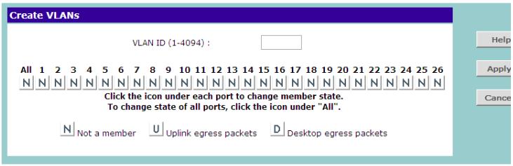
Figure 15 Create VLANs Screen
4 Define the VLAN membership by setting the state of each port. To change states, click the icon under the port number repeatedly to cycle through the different states. Available states include:
N - Not a member
U - Uplink egress packets
D-Desktopegress packets
5 Click Apply to create the VLAN.
For examples on setting up VLANs, refer to "Sample VLAN Configurations".
Sample VLAN Configurations
To illustrate how you can segment network devices that are connected to the Switch, the following sample configurations are provided.
Setting Up Two VLANs on the Same Switch
Figure 16 illustrates how you can set up a simple VLAN on the Switch using desktop connections.
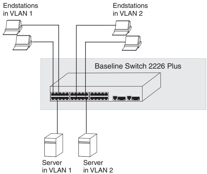
Figure 16 Desktop VLAN Configuration
If you want to add ports 7, 8, and 16 to VLAN2 (as shown in Figure 16), so that the ports on the default
VLAN1 and the ports on VLAN2 cannot communicate with each other, do the following:
- Create a new VLAN and set the VLAN ID to 2. Refer to "Creating a VLAN" for instructions. VLAN1 is the default VLAN and already exists.
2 Set ports 7, 8, and 16 to D (desktop egress packet).
3 Click Apply.
Ports 7, 8, and 16 now belong to VLAN2, and will not be able communicate with any other ports, unless you add another port to the VLAN or change the port configuration.
Setting Up VLAN Across Two Switches
This example explains how you can set up a VLAN across two Switches using uplink connections. This enables ports that are members of the same VLAN (but are on different switches) to communicate, provided that a port on each Switch is set to uplink, and that these ports are connected.
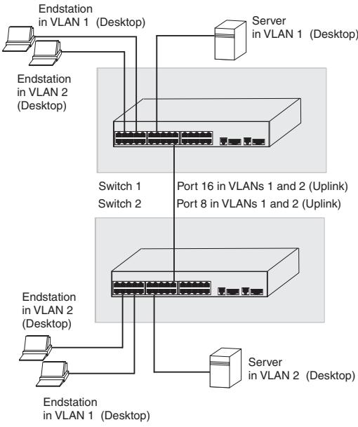
Figure 17 Uplink VLAN Configuration
To set up the configuration shown in Figure 17, do the following:
- Create VLAN2 on both Switch 1 and Switch 2, and assign the same name to it. You need not create VLAN1 since it exists by default.
2 On Switch 1, set the ports that you want to be part of VLAN2 to D (desktop egress packet). Set one port (for example, port 16) to U (uplink egress packet).
Click Apply.
3 On Switch 2, set the ports that you want to be part of VLAN2 to D (desktop egress packet). Set one port (for example, port 8) to U (uplink egress packet).
Click Apply.
4 Connect the uplink port on Switch 1 (in this example, port 16) to the uplink port on Switch 2 (in this example, port 8).
Those ports on Switch 1 that are members of VLAN2 can now communicate with those ports on Switch 2 that are members of VLAN2.
Removing a VLAN
To remove an existing VLAN:
1 In the VLAN ID list, select the VLAN ID that you want to delete.
2 Click Remove.
The VLANs page refreshes, and the VLAN ID that you deleted disappears from the VLAN ID list.
Configuring Link Aggregation
Link aggregation, also called "port trunking", refers to bonding multiple ports into a single group to effectively combine the bandwidth into a single connection or a "trunk". If you are connecting the Switch to another switch or to an Internet backbone, you can aggregate links on the Switch to increase throughput and prevent packet loopback between switches.
For link aggregation to work, the trunks must be configured on both ends (switches).

The Switch does not support the Link Aggregation Control Protocol (LACP), which is specified in IEEE 802.3ad.
Trunk Membership
The Switch has four pre-defined trunks, each of which can support up to eight ports. Table 11 lists the possible membership groups for each trunk.
Table 11 Port Groups and Members
| Port Group | Ports |
| AL1 | Ports 1-4, 13-16 |
| AL2 | Ports 5-8, 17-20 |
| AL3 | Ports 9-12, 21-24 |
| AL4 | Ports 25 and 26 (RJ-45 ports only) |
These four port groups correspond to the four separate physical connector blocks on the front panel of the Switch. You cannot trunk ports that belong to different port groups.
A trunk can consist of either 10/100 ports or 10/100/1000 ports (fixed ports 25 and 26). It is not possible to have a trunk containing a mixture of 10/100 and 10/100/1000 ports. Adding port 25 or 26 to a trunk containing 10/100 ports will result in an error.
A trunk created using ports 25 and 26 can only use the fixed RJ45 10/100/1000 ports. SFP ports cannot be aggregated.

If a port is a member of an aggregated link (or trunk), you will not be able to configure its individual port settings. All member ports of an aggregated link will have the same settings, and you can configure these by clicking the AL link on the Port Configuration screen. See "Configuring Trunk Settings" on page 38.
Adding Ports to a Trunk
To add ports to a trunk:
1 On the menu, click Link Aggregation. The Link Aggregation screen appears.
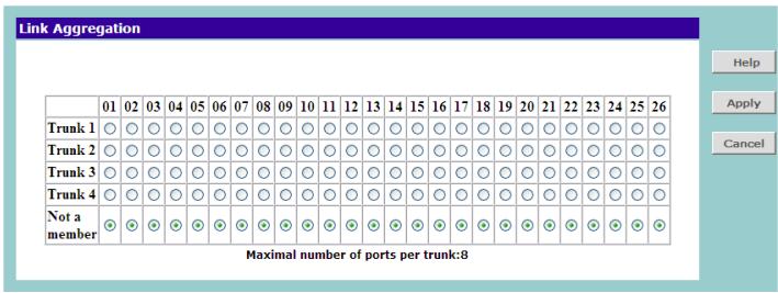
Figure 18 Link Aggregation Screen
2 Add ports to a trunk by selecting the option buttons for the ports. For example, if you want to add ports 1 to 4 to Trunk 1, click the option buttons under ports 01 to 04 that are on the same row as Trunk 1.
Each trunk must not have more than eight member ports.
3 Click Apply.

CAUTION: If you try to add a port to a trunk and the speed setting of the port to be added does not match that of the trunk, an error message appears and port will not be added to the trunk.
Configuring Trunk Settings
Ports that are members of the same trunk will have the same speed/duplex, autonegotiation, and flow control settings. You cannot configure these settings for individual member ports.
To configure the settings of a trunk's member ports:
1 On the menu, click Port Configuration. The Port Configuration screen appears.
2 Under the Port column, click the port group that you want to configure. The Port Settings screen appears.
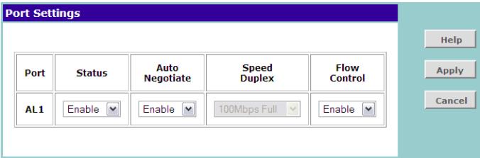
Figure 19 Port Settings Screen
3 Configure the status, autonegotiation, speed/duplex, and flow control settings of the trunk as you would configure an individual port (see available options in Table 10). Note however that these settings will be applied to all members of the trunk.
4 Click Apply to save your changes.
Viewing Statistics
The Statistics screen shows a summary of traffic statistics for all ports, as shown in Figure 20.
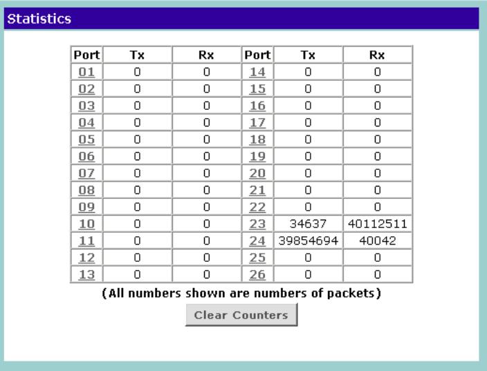
Figure 20 Statistics Screen
Figures that appear onscreen indicate the number of packets transmitted (Tx) and received (Rx).
- To reset all packet counts to zero, click Clear Counters.
- To view detailed statistics for each port, click the port number. The statistics page for the port appears, as shown in Figure 21.
Figure 21 Port Statistics Screen
| Statistics | |||
| Port | 23 | ||
| TX | |||
| UnicastPkts | 108483 | MulticastPkts | 2362 |
| BroadcastPkts | 2557 | Single Collision | 0 |
| Multi Collisions | 0 | ||
| 64 BytePkts | N/A | 65-127 BytePkts | N/A |
| 128-255 BytePkts | N/A | 256-511 BytePkts | N/A |
| 512-1023 BytePkts | N/A | 1024-1522 BytePkts | N/A |
| RX | |||
| UnicastPkts | 105668 | MulticastPkts | 479231 |
| BroadcastPkts | 1263033 | FCSErrors | 0 |
| AlignErrors | 0 | SymbolErrors | 0 |
| FragmentPkts | 0 | OverSizePkts | 0 |
| 64 BytePkts | 335070 | 65-127 BytePkts | 710641 |
| 128-255 BytePkts | 63416 | 256-511 BytePkts | 34188 |
| 512-1023 BytePkts | 10789 | 1024-1522 BytePkts | 693828 |

Figures on the Statistics screen for individual ports are not updated in real time. To view the latest statistics for the port, click Refresh.
Monitoring Traffic
The Switch allows you to monitor traffic going in and out of a particular port. For traffic monitoring to work, you need to attach a network analyzer to one port and use it to monitor the traffic of other ports in the stack.
To set up traffic monitoring, you need to set an analysis port (the port that is connected to the analyzer), and a monitor port (the port that is to be monitored). Once the pair is defined, and you enable traffic moni
toring, the Switch takes all the traffic going in and out of the monitor port and copies it to the analysis port.

CAUTION: The analysis port (Mirror From) should have a higher bandwidth than the monitor port (Mirror From). Otherwise, the Switch may not be able to copy all traffic effectively during periods of high traffic.
To set up traffic monitoring for a port:
1 Attach a network analyzer to a port.
2 Access the Web interface, and then click Traffic Monitoring on the menu.
3 On the Port Mirroring screen, select the Enable check box.
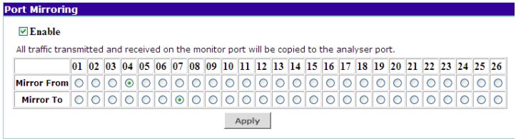
Figure 22 Traffic Monitoring Screen
4 In Mirror From, click the port number that you want to monitor.

Only one port can be selected from the Mirror Form row, which means that you can only monitor one port at any given time.
5 In Mirror To, click the port number to which the port analyzer is connected. Traffic to and from the port selected in Mirror From will be forwarded to this port.
6 Click Apply.
For information on how to interpret the output on the port analyzer, refer to its accompanying documentation.
Setting the Traffic Priority
You can configure traffic prioritization for devices and view a list of detected IP phones on the Traffic Prioritization screen. To access this screen, click Traffic Prioritization on the menu.
IP Phone Prioritization
Enable NBX Phone Prioritization
Enable Phone MAC Address-based Prioritization
Apply

Figure 23 Traffic Prioritization Screen


-XX-XX-XX
Disable Phone Prioritization
List of detected phones
Delete All
Item
Source MAC
VID
Port D
Refresh
The Traffic Prioritization screen has two sections:
IP Phone Prioritization
List of Detected Phones
IP Phone Prioritization
Use the IP Phone Prioritization section to enable or disable traffic prioritization for NBX or other IP phones. Table 12 lists the available options for this section.

CAUTION: To ensure that the Switch recognizes the NBX or other IP phone during phone initialization, do not connect any data source to the phone until the phone has finished booting up.
Once the phone is available for use, any data source (for example, a computer) can then be connected to the phone's pass-through port. This only applies if you use a single wall jack for your network connection and use the pass-through LAN port on the IP phone.
Table 12 IP Phone Prioritization Options
| Option | Description |
| Enable NBX Phone Pri- oritization | Select to automatically detect and promiatize traffic from all NBX phones that are connected to the Switch. |
| By default, this option is selected. | |
| Enable Phone MAC Address-based Prioriti- zation | If you are not using NBX phones and you know the Organizational Unique Identifier (OUI) for the phones, select this option, and then type the OUI in the fields provided. |
| If this option is selected and the OUI specified, the Switch will auto- matically detect these phones and promiatitize traffic to and from them. | |
| An OUI (sometimes called ‘vendor ID’) is the first 24 bits of a MAC address for a network-connected device (in this case, a phone), which indicate the specific vendor for that device. | |
| Disable Phone Prioritiza- tion | Select to disable traffic pri- oritization for IP phones on the Switch |
If you change any of these settings, click Apply in the IP Phone Prioritization section to save your changes.
List of Detected Phones
This section displays the MAC addresses of IP phones that are detected and given priority by the Switch. To display a phone that is connected to a port, select the port from the drop-down list.
Upgrading the Firmware
3Com may release upgrade files for the firmware that is installed on the Switch. These firmware upgrades normally contain feature enhancements and fixes for known issues in previous releases.
To upgrade the firmware, there are two tasks that you need to perform:
1 Download the firmware upgrade file from the 3Com Web site
2 Install the new firmware on the Switch
Downloading Firmware Updates
You can periodically check the 3Com Web site (www.3Com.com) for firmware updates to the Switch.
To check for and download available firmware updates:
1 On the computer that you normally use to access the Switch's Web interface, start the Web browser, and then enter www.3com.com in the Address or Location bar.
2 Click Support & Downloads, and then click Downloads & Drivers. The Search for Downloads page appears.
3 In Enter a Product Number, enter 3C16475BS, and then click Quick Search. 3C16475BS is the product number for 3Com Baseline Switch 2226 Plus.
The Download Search Results page displays any available download for the Switch.
4 If a firmware update is available, download the update files to the admin computer (computer that you use to access the Web interface).
Installing the Firmware on the Switch
After you finish downloading the upgrade files to the admin computer, you are ready to perform the firmware upgrade.
To install the firmware:
1 On the admin computer, start your Web browser, and then log on to the Switch's Web interface.
2 On the menu, click Upgrade. The Upgrade screen appears.
3 Click Yes to confirm that you want to upgrade the firmware.

CAUTION: DO NOT interrupt the firmware upgrade process once it has started.
The Switch prepares for the upgrade process.
4 Click Continue.
5 Click Browse. A Choose File dialog box appears.
6 Select the upgrade file that you downloaded from the 3Com Web site, and then click Open.
7 On the Firmware Upgrade screen, click Upgrade.
The Switch copies the upgrade file on to itself, and then restarts. A progress bar on the Firmware Upgrade screen shows the progress of the upgrade.
When the upgrade process is complete, the message Firmware Upgrade Success appears.
8 Click Continue. The Status screen appears.
To verify that the upgrade was successfully completed, check if the Firmware Version number on the Status. It should show the version of the firmware that you have just installed.
5 TROUBLESHOOTING
This chapter lists some issues that you may encounter while installing, using, and managing the Switch, with suggested courses of corrective action to take.
If you encounter an issue that is not listed here and you cannot solve it, check the 3Com Knowledgebase at http://knowledgebase.3com.com before contacting your local technical support representative.
For more information on how to obtain support for your Switch, refer to Appendix A.
Resetting to Factory Defaults
If the Switch does not operate normally or if the firmware becomes corrupted, you can reset the Switch to its factory defaults.

CAUTION: Resetting the Switch to its factory defaults erases all your settings. You will need to reconfigure the Switch after you reset it.
To reset the Switch to its factory defaults:
- Using the tip of a pen (or a similar object), press the Recovery button on the rear panel of the Switch. See Figure 1 for illustration.
2 Power off the Switch, and then power it back on, while keeping the Recovery button pressed.
3 Release the Recovery button.
4 Reset the Switch either by:
- Accessing the Web interface using Discovery, and then pressing the RESET button on the Fail-Safe Mode screen (see Figure 24). The Fail-Safe Mode screen appears (instead of the logon screen) after you perform steps 1 to 3 of this procedure.
- Powering off the Switch, and then powering it back on.

The Switch will perform automatic IP configuration after you reset it. See "Automatic IP Configuration" on page 29 for more information.
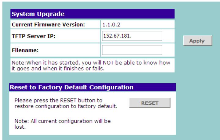
Figure 24 Fail-Safe Mode Screen
Forgotten Password
If you forget the password to the Web interface after you set it, you will need to reset the Switch to regain access. See "Resetting to Factory Defaults" on page 43 for instructions. After resetting the Switch, you can log on to the Web interface again using the default admin account settings:
■ User name - admin
- Password - blank (no password)
Forgotten Static IP Address
If you forget the static IP address that you assigned to the Switch and you need to access the Web interface, use the Discovery application to automatically detect the IP address and connect to the interface.
For information on using the Discovery application, refer to "Running the Discovery Application" on page 21.
Solving LED Issues
This section lists some issues that are related to the LEDs on the front panel of the Switch. For information on basic LED checks, refer to the following topics in Chapter 1:
(2) Module Active LEDs
(3) Link/Activity LEDs
(5) Power LED
(6) Duplex LEDs
A link is connected, but the Link/Activity LED for the port is off.
There is a problem with this connection. Verify that:
- The device being connected to is powered on and operating correctly.
The cable is connected at both ends.
The cable is not damaged.
If the connection is to a workstation, that the workstation's network interface is installed and configured correctly. - The correct category of cable is being used for the required link speed. Category 3 cables can be used for 10BASE-T operation only. Category 5 cable is required for 100BASE-TX or 1000BASE-T. 3Com recommends Category 5e or 6 cables for 1000BASE-T operation.
A fiber cable is connected, but the Module Active LED is off.
Verify that:
The fiber cable is in good condition.
The SFP module is correctly inserted.
A 3Com SFP module is being used. Refer to "Approved SFP Transceivers" on page 18 for details.
- The equipment at the far end is installed and correctly configured.
The Link/Activity LED is on, but network performance is poor.
The Switch supports full-duplex autonegotiation. If the connected device does not support autonegotiation, ensure that it is configured for half-duplex operation only. If the connected device has autonegotiation disabled or overridden, and is configured as full-duplex, the Switch will configure the link as half-duplex, causing a mismatch that will reduce network performance when data is transmitting and receiving simultaneously on the same link.
Ensure that the connected device has either:
Autonegotiation enabled, or
The ports are configured for half-duplex operation
All ports appear to show continual activity.
There may be broadcast storms on the network. Remove port connections one at a time, waiting a few seconds between each port. If the LEDs go off after removing a port connection, the device that was connected to that port is introducing an excessive amount of broadcast frames to the network. Some pieces of network equipment operate by sending out broadcast frames regularly.
Refer to the documentation that accompanies the device for information on disabling the broadcast operation.
Solving Corrupted Firmware
If the firmware becomes corrupted, you must either:
Upgrade the firmware for the Switch
Reset the Switch to factory defaults
When the firmware is corrupted, the Switch automatically goes into Fail-Safe mode.
To upgrade a corrupted firmware:
1 Download the latest firmware from the 3Com Web site to the computer that you are using to access the Web interface.
2 Access the Web interface. The Fail-Safe Mode screen appears, as shown in Figure 24.
3 Click Browse, and then follow the onscreen instructions to upgrade the Switch to the required version of firmware.
To reset the Switch to its factory defaults, follow the instructions in "Resetting to Factory Defaults" on page 43.

CAUTION: Before recovering the Switch, save the Switch's current configuration. Recovering the Switch will cause the current configuration to be lost.
If the Problem persists
If the problem persists and the unit still does not operate successfully, contact your 3Com network supplier with the following information before returning the unit:
Product number and serial number (printed on a label supplied with the unit).
A brief description of the issue
A OBTAINING SUPPORT FOR YOUR PRODUCT
Register Your Product
Warranty and other service benefits start from the date of purchase, so it is important to register your product quickly to ensure you get full use of the warranty and other service benefits available to you.
Warranty and other service benefits are enabled through product registration. Register your product at http://eSupport.3com.com/. 3Com eSupport services are based on accounts that you create or have authorization to access. First time users must apply for a user name and password that provides access to a number of eSupport features including Product Registration, Repair Services, and Service Request. If you have trouble registering your product, please contact 3Com Global Services for assistance.
Purchase Value-Added Services
To enhance response times or extend warranty benefits, contact 3Com or your authorized 3Com reseller. Value-added services like 3Com Express™ and Guardian™ can include 24x7 telephone technical support, software upgrades, onsite assistance or advance hardware replacement. Experienced engineers are available to manage your installation with minimal disruption to your network. Expert assessment and implementation services are offered to fill resource gaps and ensure the success of your networking
projects. More information on 3Com maintenance and Professional Services is available at http://www.3com.com/
Contact your authorized 3Com reseller or 3Com for a complete list of the value-added services available in your area.
Troubleshoot Online
You will find support tools posted on the 3Com web site at http://www.3com.com/
3Com Knowledgebase helps you troubleshoot 3Com products. This query-based interactive tool is located at http://knowledgebase.3com.com and contains thousands of technical solutions written by 3Com support engineers.
Access Software Downloads
Software Updates are the bug fix / maintenance releases for the version of software initially purchased with the product. In order to access these Software Updates you must first register your product on the 3Com web site at http://eSupport.3com.com/.
First time users will need to apply for a user name and password. A link to software downloads can be
found at http://eSupport.3com.com/, or under the Product Support heading at http://www.3com.com/
Software Upgrades are the software releases that follow the software version included with your original product. In order to access upgrades and related documentation you must first purchase a service contract from 3Com or your reseller.
Telephone Technical Support and Repair
To obtain telephone support as part of your warranty and other service benefits, you must first register your product at http://eSupport.3com.com/
Warranty and other service benefits start from the date of purchase, so it is important to register your product quickly to ensure you get full use of the warranty and other service benefits available to you.
When you contact 3Com for assistance, please have the following information ready:
Product model name, part number, and serial number
Proof of purchase, if you have not pre-registered your product
A list of system hardware and software, including revision level
Diagnostic error messages
Details about recent configuration changes, if applicable
To send a product directly to 3Com for repair, you must first obtain a return authorization number (RMA). Products sent to 3Com, without authorization numbers clearly marked on the outside of the package, will be returned to the sender unopened, at the sender's expense. If your product is registered and under warranty, you can obtain an RMA number online at http://eSupport.3com.com/. First time users will need to apply for a user name and password.
Contact Us
3Com offers telephone, e-mail and internet access to technical support and repair services. To access these services for your region, use the appropriate telephone number, URL or e-mail address from the list below.
Telephone numbers are correct at the time of publication. Find a current directory of support telephone numbers posted on the 3Com web site at http://csomeb4.3com.com/contactus/
| Country | Telephone Number |
| Asia, Pacific Rim Telephone Technical Support and Repair | |
| Australia | 1 800 678 515 |
| Hong Kong | 800 933 486 |
| India | +61 2 9424 5179 or 000800 6501111 |
| Indonesia | 001 803 61 009 |
| Japan | 00531 616 439 or 03 3507 5984 |
| Malaysia | 1800 801 777 |
| New Zealand | 0800 446 398 |
| Pakistan | +61 2 9937 5083 |
| Philippines | 1235 61 266 2602 or 1800 1 888 9469 |
| P.R. of China | 800 810 3033 |
| Singapore | 800 6161 463 |
| S. Korea | 080 333 3308 |
| Taiwan | 00801 611 261 |
| Thailand | 001 800 611 2000 |
You can also obtain support in this region using the following e-mail: apr_technical_support@3com.com
Or request a repair authorization number (RMA) by fax using this number: +65 543 6348
Europe, Middle East, and Africa Telephone Technical Support and Repair
From anywhere in these +44 (0)1442 435529 regions, call:
From the following countries, you may use the numbers shown:
| Country | Telephone Number |
| Austria | 01 7956 7124 |
| Belgium | 070 700 770 |
| Denmark | 7010 7289 |
| Finland | 01080 2783 |
| France | 0825 809 622 |
| Germany | 01805 404 747 |
| Hungary | 06800 12813 |
| Ireland | 1407 3387 |
| Israel | 1800 945 3794 |
| Italy | 199 161346 |
| Luxembourg | 342 0808128 |
| Netherlands | 0900 777 7737 |
| Norway | 815 33 047 |
| Poland | 00800 441 1357 |
| Portugal | 707 200 123 |
| South Africa | 0800 995 014 |
| Spain | 9 021 60455 |
| Sweden | 07711 14453 |
| Switzerland | 08488 50112 |
| U.K. | 0870 909 3266 |
You can also obtain support in this region using the following URL: http://emea.3com.com/support/email.html
| Country | Telephone Number |
Latin America Telephone Technical Support and Repair
From the Caribbean, Central and South America, call:
| Country | Telephone Number |
| Antigua | 1 800 988 2112 |
| Argentina | 0 810 444 3COM |
| Aruba | 1 800 998 2112 |
| Bahamas | 1 800 998 2112 |
| Barbados | 1 800 998 2112 |
| Belize | 52 5 201 0010 |
| Bermuda | 1 800 998 2112 |
| Bonaire | 1 800 998 2112 |
| Brazil | 0800 13 3COM |
| Cayman | 1 800 998 2112 |
| Chile | AT&T +800 998 2112 |
| Colombia | AT&T +800 998 2112 |
| Costa Rica | AT&T +800 998 2112 |
| Curacao | 1 800 998 2112 |
| Ecuador | AT&T +800 998 2112 |
| Dominican Republic | AT&T +800 998 2112 |
| Guatemala | AT&T +800 998 2112 |
| Haiti | 57 1 657 0888 |
| Honduras | AT&T +800 998 2112 |
| Jamaica | 1 800 998 2112 |
| Martinique | 571 657 0888 |
| Mexico | 01 800 849CARE |
| Nicaragua | AT&T +800 998 2112 |
| Panama | AT&T +800 998 2112 |
| Paraguay | 54 11 4894 1888 |
| Peru | AT&T +800 998 2112 |
| Puerto Rico | 1 800 998 2112 |
| Salvador | AT&T +800 998 2112 |
| Trinidad and Tobago | 1 800 998 2112 |
| Uruguay | AT&T +800 998 2112 |
| Venezuela | AT&T +800 998 2112 |
| Virgin Islands | 57 1 657 0888 |
| Country | Telephone Number |
| You can also obtain support in this region using the follow- ing: | |
| Spanish speakers, enter the URL: http://lat.3com.com/lat/support/form.html | |
| Portuguese speakers, enter the URL: http://lat.3com.com/br/support/form.html | |
| English speakers in Latin America should send e-mail to: lat_support_anc@3com.com | |
| US and Canada Telephone Technical Support and Repair | |
| 1 800 876 3266 | |
B SAFETY INFORMATION
Important Safety Information
Please read the following safety information carefully before installing the 3Com Baseline Switch 2226 Plus.

WARNING: Installation and removal of the unit must be carried out by qualified personnel only.

WARNING: If installing the Switch unit in a stack with other units, the Switch unit must be installed below the narrower units and above the deeper units.

WARNING: The unit must be earthed (grounded) to ensure compliance with safety standards.

WARNING: The appliance coupler (the connector to the unit and not the wall plug) must have a configuration for mating with an EN60320/IEC320 appliance inlet.

WARNING: The socket outlet must be near to the unit and easily accessible. You can only remove power from the unit by disconnecting the power cord from the outlet.

WARNING: This unit operates under SELV (Safety Extra Low Voltage) conditions according to IEC 60. The conditions are only maintained if the equipment to which it is connected also operates under SELV conditions.

WARNING: France and Peru only
This unit cannot be powered from I T^+ supplies. If your supplies are of IT type, this unit must be powered by 230 V (2P+T) via an isolation transformer ratio 1:1, with the secondary connection point labelled Neutral, connected directly to earth (ground).
WARNING: Power cord set
This must be approved for the country where it will be used.
| U.S.A. and Canada | The cord set must be UL-approved and CSA certified. |
| The minimum specifications for the flexible cord are: No. 18 AWG Type SV or SJ 3-conductor | |
| The cord set must have a rated current capacity of at least 10 A. | |
| The attachment plug must be an earth-grounding type with a NEMA 5-15P (15 A, 125 V) or NEMA 6-15P (15 A, 250 V) configuration. | |
| Denmark | The supply plug must comply with Section 107-2-D1, Standard DK2-1a or DK2-5a. |
| Switzerland | The supply plug must comply with SEV/ASE 1011. |
| UK | ■ The supply plug must comply with BS1363 (3-pin 13-amp) and be fitted with a 5 A fuse which complies with BS1362. |
| ■ The mains cord must be <HAR> or <BASEC> marked and be of type HO3VVF3GO.75 (minimum). | |
| Europe | ■ The supply plug must comply with CEE7/7 ("SCHUKO") |
| ■ The mains cord must be <HAR> or <BASEC> marked and be of type HO3VVF3GO.75 (minimum). |

WARNING: Fiber optic ports - optical safety

Never look at the transmit laser while it is powered on. Never look directly at the fiber ports and fiber cable ends when they are powered on.

WARNING: Use of controls or adjustments of performance or procedures other than those specified herein may result in hazardous laser emissions.
The 3Com Baseline Switch 2226 Plus has been designed to the following standards:
| Functional | ISO 8802-3, IEEE 802.3 (Ethernet), IEEE 802.3u (Fast Ethernet), IEEE 802.3ab and IEEE 802.3z (Gigabit Ethernet), IEEE 802.3x (Flow Control), IEEE 802.1D 1998 (Bridging) |
| MAC Address | 4096 |
| Safety | UL 60950-1 & CAS 60950-1 (CSA/CUS), IEC 60950-1(CE), EN 60950-1 (TÜV/GS) |
| EMC Emissions | EN 55022 Class A, FCC Part 15 Subpart B Class A, ICES-003 Class A, VCCI Class A |
| Immunity | EN 55024 |
Environmental
| Operating Temperature | 0–50 °C (32–113 °F) |
| Humidity | 10–95% (non-condensing) |
| Standard | EN 60068 (IEC 68)—various parts |
Physical
| Width | 440 mm (17.3 in.) |
| Length | 173 mm (6.8 in.) |
| Height | 43.6 mm (1.75 in.) or 1U |
| Weight | 1.7 kg (3.8 lb) |
| Mounting | Free-standing, or 19 in. rack-mounted using the supplied mounting kit |
Electrical
| Power Inlet | IEC 320 |
| AC Line Frequency | 50/60 Hz |
| Input Voltage | 100–240 VAC |
| Current Rating | 1 ampere (maximum) |
| Maximum Power Con-sumption | 196 watts |
| Maximum Power Dissi-pation | 668.95 BTU/hr |
GLOSSARY
10BASE-T
The IEEE specification for 10 Mbps Ethernet over Category 3, 4 or 5 twisted pair cable.
100BASE-TX
The IEEE specification for 100 Mbps Fast Ethernet over Category 5 twisted-pair cable.
1000BASE-LX
IEEE 802.3z specification for Gigabit Ethernet over 9/125 micron core single-mode fiber cable.
1000BASE-SX
IEEE 802.3z specification for Gigabit Ethernet over two strands of 50/125 or 62.5/125 micron core multi-mode fiber cable.
1000BASE-T
IEEE 802.3ab specification for Gigabit Ethernet over 100-ohm Category 5, 5e or 6 twisted-pair cable (using all four wire pairs).
autonegotiation
Autonegotiation is where two devices sharing a link, automatically configure to use the best common speed. The order of preference (best first) is: 1000BASE-T full-duplex, 100BASE-TX full-duplex, 100BASE-TX half-duplex, 10BASE-T full-duplex, and 10BASE-T half-duplex. Autonegotiation is defined in
the IEEE 802.3 standard for Ethernet and is an operation that takes place in a few milliseconds. Autonegotiation must be enabled for the 1000BASE-T ports to operate at 1000 Mbps, full-duplex.
bandwidth
The information capacity (measured in bits per second) that a channel can transmit. The bandwidth of Ethernet is 10 Mbps, the bandwidth of Fast Ethernet is 100 Mbps and Gigabit Ethernet is 1000 Mbps.
category 3 cable
One of five grades of Twisted Pair (TP) cabling defined by the EIA/TIA-568 standard. Category 3 is voice grade cable and can only be used in Ethernet networks (10BASE-T) to transmit data at speeds of up to 10 Mbps.
category 5 cable
One of five grades of Twisted Pair (TP) cabling defined by the EIA/TIA-568 standard. Category 5 can be used in Ethernet (10BASE-T) and Fast Ethernet networks (100BASE-TX) and can transmit data at speeds of up to 100 Mbps. Category 5 cabling is better to use for network cabling than Category 3, because it supports both Ethernet (10 Mbps) and Fast Ethernet (100 Mbps) speeds.
category 5e cables
One of five grades of Twisted Pair (TP) cabling defined by the EIA/TIA-568 standard. Category 5e can be used in Ethernet (10BASE-T), Fast Ethernet (100BASE-TX) and Gigabit Ethernet (1000BASE-T) networks, and can transmit data at speeds of up to 1000 Mbps.
category 6 cable
One of five grades of Twisted Pair (TP) cabling defined by the EIA/TIA-568-B standard. Category 6 can be used in Ethernet (10BASE-T), Fast Ethernet (100BASE-TX) and Gigabit Ethernet (1000BASE-T) networks, and can transmit data at speeds of up to 1000 Mbps.
client
The term used to describe the desktop PC that is connected to your network.
DHCP
Dynamic Host Configuration Protocol. This protocol automatically assigns an IP address for every computer on your network. Windows 95, Windows 98 and Windows NT 4.0 contain software that assigns IP addresses to workstations on a network. These assignments are made by the DHCP server software that runs on Windows NT Server.
Ethernet
A LAN specification developed jointly by Xerox, Intel and Digital Equipment Corporation. Ethernet networks use CSMA/CD to transmit packets at a rate of 10 Mbps and 100 Mbps over a variety of cables.
Ethernet address
See MAC address.
Fast Ethernet
An Ethernet system that is designed to operate at 100 Mbps.
Gigabit Ethernet
An Ethernet system that is designed to operate at 1000 Mbps.
full-duplex
A system that allows packets to be transmitted and received at the same time and, in effect, doubles the potential throughput of a link.
half-duplex
A system that allows packets to be transmitted and received, but not at the same time. Half-duplex is not supported for 1000 Mbps. Contrast with full-duplex.
IEEE
Institute of Electrical and Electronics Engineers. This American organization was founded in 1963 and sets standards for computers and communications.
IEEE 802.1D
Specifies a general method for the operation of MAC bridges, including the Spanning Tree Protocol.
IEEE 802.1Q
VLAN Tagging - Defines Ethernet frame tags that carry VLAN information. It allows switches to assign endstations to different virtual LANs, and defines a
standard way for VLANs to communicate across switched networks.
IEEE 802.1p
An IEEE standard for providing quality of service (QoS) in Ethernet networks. The standard uses packet tags that define up to eight traffic classes and allows switches to transmit packets based on the tagged priority value.
IEEE 802.3ad
A standard that defines link aggregation. 802.3ad is now incorporated into the relevant sections of the IEEE Std. 802.3-2002.
IETF
Internet Engineering Task Force. An organization responsible for providing engineering solutions for TCP/IP networks. In the network management area, this group is responsible for the development of the SNMP protocol.
IP
Internet Protocol. IP is a layer 3 network protocol that is the standard for sending data through a network. IP is part of the TCP/IP set of protocols that describe the routing of packets to addressed devices. An IP address consists of 32 bits divided into two or three fields: a network number and a host number or a network number, a subnet number, and a host number.
IP Address
Internet Protocol Address. A unique identifier for a device attached to a network using TCP/IP. The
address is written as four octets separated with periods (full-stops), and is made up of a network section, an optional subnet section and a host section.
LAN
Local Area Network. A network of end stations (such as PCs, printers, servers) and network devices (hubs and switches) that cover a relatively small geographic area (usually not larger than a floor or building). LANs are characterized by high transmission speeds over short distances (up to 1000 meters).
Layer 2
Data Link layer in the ISO 7-Layer Data Communications Protocol. This is related directly to the hardware interface for the network devices and passes on traffic based on MAC addresses.
link aggregation
See Trunking.
MAC
Media Access Control. A protocol specified by the IEEE for determining which devices have access to a network at any one time.
MAC address
Media Access Control Address. Also called the hardware, physical, or Ethernet address. A layer 2 address associated with a particular network device. Most devices that connect to a LAN have a MAC address assigned to them as they are used to identify other devices in a network. MAC addresses are 6 bytes long.
network
A network is a collection of computers and other computer equipment that are connected for the purpose of exchanging information or sharing resources. Networks vary in size, some are within a single room, others span continents.
ping
Packet Internet Groper. An internet utility used to determine whether a particular IP address is online. It is used to test and debug a network by sending out a packet and waiting for a response.
protocol
A set of rules for communication between devices on a network. The rules dictate format, timing, sequencing and error control.
RJ-45
A standard connector used to connect Ethernet networks. The "RJ" stands for "registered jack."
server
A computer in a network that is shared by multiple end stations. Servers provide end stations with access to shared network services such as computer files and printer queues.
SFP
Small Form Factor Pluggable (SFP) Connectors are based on an open standard that enables hot swapping of various types of fiber optic and copper-based transceivers into the host equipment.
subset address
An extension of the IP addressing scheme that allows a site to use a single IP network address for multiple physical networks.
subset mask
A subnet mask, which may be a part of the TCP/IP information provided by your ISP, is a set of four numbers configured like an IP address. It is used to create IP address numbers used only within a particular network (as opposed to valid IP address numbers recognized by the Internet, which must assigned by InterNIC).
subset
A network that is a component of a larger network.
switch
A device that interconnects several LANs to form a single logical LAN that comprises of several LAN segments. Switches are similar to bridges, in that they connect LANs of a different type; however they connect more LANs than a bridge and are generally more sophisticated.
TCP/IP
Transmission Control Protocol/Internet Protocol. This is the name for two of the most well-known protocols developed for the interconnection of networks. Originally a UNIX standard, TCP/IP is now supported on almost all platforms, and is the protocol of the Internet.
TCP relates to the content of the data travelling through a network — ensuring that the information sent arrives in one piece when it reaches its destination. IP relates to the address of the end station to which data is being sent, as well as the address of the destination network.
traffic monitoring
Enables the monitoring of port traffic by attaching a network analyzer to one switch port, in order to monitor the traffic of other ports on the Switch.
trunking
A method that specifies how to combine several lower-speed physical links to create a single high-speed logical link.
VLAN
Virtual LAN. A collection of network nodes that share the same collision domain regardless of their physical location or connection point in the network. A VLAN serves as a logical workgroup with no physical barriers, and allows users to share information and resources as though located on the same LAN.
INDEX
Numbers
1000BASE-LX 61
1000BASE-SX 61
1000BASE-T 61
100BASE-TX 61
10BASE-T 61
A
auto IP configuration 29
default IP address 29
default mask 29
autonegotiation 7,32
autosensing 7
B
bandwidth 61
C
client 62
configuration
overview 27
connecting
network device 17
SFP transceivers 18
conventions
notice icons, About This Guide 5
text, About This Guide 5
D
DHCP 62
Discovery 21
dynamic host control protocol See DHCP
E
Ethernet 62
F
fail-safe mode 43, 45
Fast Ethernet 62
flow control 33
forgotten IP address 44
forgotten password 44
free-standing 14
front panel
Duplex LEDs 12
Link/Activity LEDs 10
Module Active LEDs 10
PowerLED 11
RJ-45 ports 9
self-adhesive pads 12
SFP ports 11
full-duplex 62
G
Gigabit Ethernet 62
H
half-duplex 62
1
IEEE 62
IETF 63
installing 13
IP address
auto configuration 29
modifying 29
setting 30
IP defined 63
L
LAN defined 63
LED issues 44
LEDs
Duplex 12
Link/Activity 10
Module Active 10
Power 11
link aggregation 36
local area network 63
M
MAC address 63
media access control 63
monitoring traffic 39
mounting kit
contents 13
using 15
N
network analyzer 39
network cables
category 3 61
category 5 61
category 5e 62
category 6 62
network defined 64
P
package contents 12
panels
front 9
rear 12
password
changing 28
default (blank) 28
setting 28
physical features 9
port settings
configuring 31
default settings 31
flow control 33
modifying individual ports 32
speed/duplex 33
viewing 31
ports
RJ-45 9
SFP 8,11
positioning 13
POST 17
powering on 16
power-on self-test See POST
prioritization
IP phones 40
protocol defined 64
R
rack-mounting 14
rear panel
power supply 12
Recovery button 12
resetting to factory defaults 43
RJ-45
defined 64
ports 9
s
safety information
German 54
server defined 64
SFP ports 8,11
SFP transceivers 18
approved (supported) 18
inserting 18
removing 19
speed/duplex 33
spot checks 19
subset mask 64
switch defined 64
T
TCP/IP 63
defined 64
traffic 65
monitoring 39
setting the priority 40
traffic prioritization 8, 40
IP phones 8
priorityqueuing 8
traffic priority levels 8
troubleshooting 43
corrupted firmware 45
forgotten IP address 44
forgotten password 44
LED-related issues 44
POST failed 17
trunking See link aggregation
U
user name
default 28
V
viewing
detected IP phones 41
individual port statistics 38
port settings 31
statistics 38
status information 27
VLANs 33
creating 34, 36
desktop 34
maximum supported 33
not a member 34
removing 36
sample configurations 35
uplink 34
W
Web interface
accessing directly 24
accessing using Discovery 21
buttons 24
connecting 21
logging on 22
menu 23
navigating 23
requirements for accessing 21
REGULATORY NOTICES
FCC STATEMENT
This equipment has been tested and found to comply with the limits for a Class A digital device, pursuant to part 15 of the FCC rules. These limits are designed to provide reasonable protection against harmful interference when the equipment is operated in a commercial environment. This equipment generates, uses and can radiate radio frequency energy and, if not installed and used in accordance with the instructions, may cause harmful interference to radio communications. Operation of this equipment in a residential area is likely to cause harmful interference to radio communications, in which case the user will be required to correct the interference at their own expense.
INFORMATION TO THE USER
If this equipment does cause interference to radio or television reception, which can be determined by turning the equipment off and on, the user is encouraged to try to correct the interference by one or more of the following measures:
Reorient the receiving antenna.
Relocate the equipment with respect to the receiver.
Move the equipment away from the receiver.
Plug the equipment into a different outlet so that equipment and receiver are on different branch circuits.
If necessary, the user should consult the dealer or an experienced radio/television technician for additional suggestions. The user may find the following booklet prepared by the Federal Communications Commission helpful:
How to Identify and Resolve Radio-TV Interference Problems
This booklet is available from the U.S. Government Printing Office, Washington,
DC 20402, Stock No. 004-000-00345-4.
In order to meet FCC emissions limits, this equipment must be used only with cables which comply with IEEE 802.3.
CE STATEMENT (EUROPE)
This product complies with the European Low Voltage Directive 73/23/EEC and EMC Directive 89/336/EEC as amended by European Directive 93/68/EEC/.
CSA STATEMENT
This Class A digital apparatus meets all requirements of the Canadian Interference-Caising Equipment Regulations.

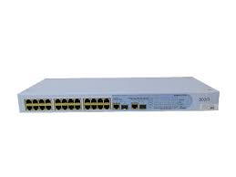
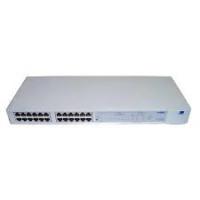
- 3Com Corporation • 350 Campus Drive • Marlborough • MA USA 01752-3064
- UNITED STATES GOVERNMENT LEGEND
- ENVIRONMENTAL STATEMENT
- End of Life Statement
- Regulated Materials Statement
- Environmental Statement about the Documentation
- CONTENTS
- ABOUT THIS GUIDE
- INTRODUCING THE BASELINE SWITCH
- INSTALLING THE SWITCH
- CONNECTING TO THE WEB INTERFACE
- CONFIGURING THE SWITCH
- TROUBLESHOOTING
- A OBTAINING SUPPORT FOR YOUR PRODUCT
- B SAFETY INFORMATION
- GLOSSARY
- INDEX
- REGULATORYNOTICES
- Conventions
- Related Documentation
- Documentation Comments
- Overview of the Baseline Switch 2226 Plus
- Features and Capabilities
- Autosensing of MDI/MDIX Connections
- Autonegotiating 10/100 Mbps Ports
- SFP Ports
- Traffic Prioritization
- Prioritization of IP Phone Traffic
- Traffic Priority Queuing
- Physical Features
- Front Panel
- 24 RJ-45 Ports
- Module Active LEDs
- Link/Activity LEDs
- 10/100/1000BASE-T/SFP Ports
- Power LED
- Duplex LEDs
- Self-Adhesive Pads
- Rear Panel
- Power Supply
- (9)Recovery Button
- Package Contents
- Before You Begin
- Positioning the Switch
- Rack-Mounting or Free-Standing
- Using the Mounting Kit
- Placing Units On Top of Each Other
- Supplying Power to the Switch
- Checking for Correct Operation
- Connecting a Network Device
- Using SFP Transceivers
- Approved SFP Transceivers
- Inserting an SFP Transceiver
- Removing an SFP Transceiver
- Performing Spot Checks
- Requirements for Accessing the Web Interface
- Running the Discovery Application
- Logging On to the Web Interface
- Navigating the Web Interface
- Menu
- Buttons
- Accessing the Interface Without Using Discovery
- DHCP Assigned IP Address
- Manually Assigned (Static) IP Address
- 4
- CONFIGURING THE SWITCH
- Configuration Overview
- Viewing Status Information
- Changing the Admin Password
- Change Administration Password
- Modifying the IP Address Settings
- Automatic IP Configuration
- Setting the IP Address
- Configuring Port Settings
- Viewing Port Settings
- Default Port Settings
- Changing a Port's Settings
- Speed/Duplex for 1000 Mbps Connections
- Configuring VLANs
- Creating a VLAN
- Sample VLAN Configurations
- Setting Up Two VLANs on the Same Switch
- Setting Up VLAN Across Two Switches
- Removing a VLAN
- Configuring Link Aggregation
- Trunk Membership
- Adding Ports to a Trunk
- Configuring Trunk Settings
- Viewing Statistics
- Monitoring Traffic
- Click Apply.
- Setting the Traffic Priority
- IP Phone Prioritization
- List of detected phones
- Upgrading the Firmware
- Downloading Firmware Updates
- Installing the Firmware on the Switch
- Resetting to Factory Defaults
- Forgotten Password
- Forgotten Static IP Address
- Solving LED Issues
- A link is connected, but the Link/Activity LED for the port is off.
- A fiber cable is connected, but the Module Active LED is off.
- All ports appear to show continual activity.
- Solving Corrupted Firmware
- If the Problem persists
- Register Your Product
- Purchase Value-Added Services
- Troubleshoot Online
- Access Software Downloads
- Telephone Technical Support and Repair
- Contact Us
- Europe, Middle East, and Africa Telephone Technical Support and Repair
- Latin America Telephone Technical Support and Repair
- Important Safety Information
- WARNING: France and Peru only
- WARNING: Power cord set
- Physical
- Electrical
- 10BASE-T
- 100BASE-TX
- 1000BASE-LX
- 1000BASE-SX
- 1000BASE-T
- autonegotiation
- bandwidth
- category 3 cable
- category 5 cable
- category 5e cables
- category 6 cable
- client
- DHCP
- Ethernet
- Ethernet address
- Fast Ethernet
- Gigabit Ethernet
- full-duplex
- half-duplex
- IEEE
- IEEE 802.1D
- IEEE 802.1Q
- IEEE 802.1p
- IEEE 802.3ad
- IETF
- IP
- IP Address
- LAN
- Layer 2
- link aggregation
- MAC
- MAC address
- network
- ping
- protocol
- RJ-45
- server
- SFP
- subset address
- subset mask
- subset
- switch
- TCP/IP
- traffic monitoring
- trunking
- VLAN
- Numbers
- A
- B
- C
- D
- E
- F
- G
- H
- 1
- L
- M
- N
- P
- R
- s
- T
- U
- V
- W
- REGULATORY NOTICES
- FCC STATEMENT
- INFORMATION TO THE USER
- CE STATEMENT (EUROPE)
- CSA STATEMENT
Brand : 3COM
Model : BASELINE SWITCH 2226 PLUS
Category : Network switch