
VISIONMOUNT FLAT PANEL WALL MOUNT-VMPL3 - Wall mount for flat screen SANUS - Free user manual and instructions
Find the device manual for free VISIONMOUNT FLAT PANEL WALL MOUNT-VMPL3 SANUS in PDF.

| Product Type | Wall mount for flat screen |
| Brand | SANUS |
| Model | VISIONMOUNT VMPL3 |
| Compatibility | LCD or plasma flat-screen TVs from 27" to 84" |
| Maximum supported weight | 127 kg |
| Wall plate dimensions (adjustable) | Width from 68.6 to 106.7 cm |
| Material | Steel |
| Functions | Tilt, low-profile mounting, adjustable extensions, security lock |
| Fixation | On wood studs (3 studs recommended for >56.7 kg), concrete, brick, cinder blocks |
| Package contents | Wall plate, monitor brackets (tilt and low profile), extensions, complete hardware, Allen wrench |
| Required tools | Drill, 3/16" bit (wood), 1/2" masonry bit (concrete/brick), wrench set, Phillips screwdriver |
| Maintenance | Clean with a soft, dry cloth. Do not use abrasive products. |
| Safety | Must be installed on a solid wall. Do not exceed maximum weight. Check fasteners regularly. |
Frequently Asked Questions - VISIONMOUNT FLAT PANEL WALL MOUNT-VMPL3 SANUS
User questions about VISIONMOUNT FLAT PANEL WALL MOUNT-VMPL3 SANUS
0 question about this device. Answer the ones you know or ask your own.
Ask a new question about this device
Download the instructions for your Wall mount for flat screen in PDF format for free! Find your manual VISIONMOUNT FLAT PANEL WALL MOUNT-VMPL3 - SANUS and take your electronic device back in hand. On this page are published all the documents necessary for the use of your device. VISIONMOUNT FLAT PANEL WALL MOUNT-VMPL3 by SANUS.
USER MANUAL VISIONMOUNT FLAT PANEL WALL MOUNT-VMPL3 SANUS
International Assembly Instructions for model VMPL3
SANUS SYSTEMS
THE UNION OF FORM AND FUNCTION
Assembly Instructions for Model: VMPL3
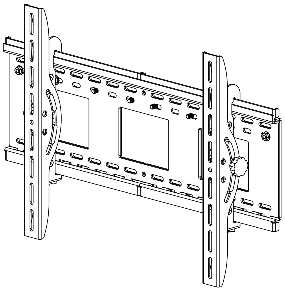
Thank you for choosing a Sanus Systems VisionMount™ Wall Mount. The VMPL3 is designed to hold 27" to 84" [686 mm to 2133 mm] Flat Panel LCD or Plasma Displays weighing up to 280 lbs [127 kg].
CAUTION: The size and weight of your large screen television must not exceed 84” [2133 mm] diagonally and 280 Lbs [127.3 Kg], the maximum load capacity of the mount. Never use defective parts. Improper installation may cause property damage or personal injury. Do not use this product for any purpose that is not explicitly specified by Sanus Systems.
If you do not understand these directions, or have any doubts about the safety of the installation, please call a qualified contractor or contact Sanus at 800.359.5520 or www.sanus.com. Our customer service representatives can quickly assist you with installation questions and missing or damaged parts. Replacement parts for products purchased through authorized dealers will be shipped directly to you. Check carefully to make sure that there are no missing or defective parts. Sanus Systems can not be liable for damage or injury caused by incorrect mounting, incorrect assembly, or incorrect use. Please call Sanus Systems before returning products to the point of purchase.
NOTE: The supplied wall mounting hardware is not for metal stud or old cinder block walls. If you are uncertain about the nature of your wall, consult an installation contractor. Sanus makes every effort to assure all necessary television mounting hardware is included. If the hardware you need is not included please consult your local hardware store or call Sanus systems.
Required Tools: Drill, 3/16" bit (1/2" masonry bit for brick, concrete, or concrete block installations), wrench set, phillips screwdriver.
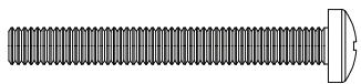
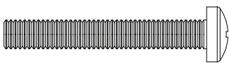
Supplied Parts and Hardware: (All threaded fasteners are shown full size.)

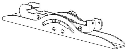
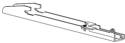
Wall Plate Assembly - A Qty. 1
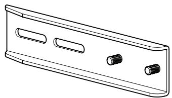
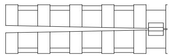
Monitor Bracket Extension - B Qty. 4
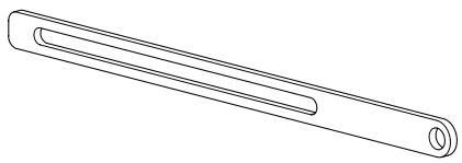
Latch Extension - C Qty. 2
Right Tilting Monitor Bracket - D Qty. 1
Left Tilting Monitor Bracket - E Qty. 1
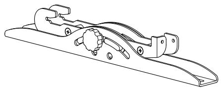
Low Profile Monitor Bracket - F Qty. 2
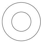
Nylon Washer - G Qty. 8
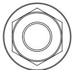
Flange Nut - H Qty. 8
Safety Bolt - I Qty. 2
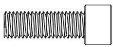
Lag Bolt - K Qty. 6

Lag Bolt Washer - L Qty. 6
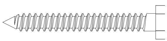
Concrete Anchor - M Qty. 6

10-32 Screw - N Qty. 4
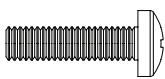
M4 x 16 mm Bolt - O Qty. 4
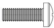
M5 x 16 mm Bolt - P Qty. 4
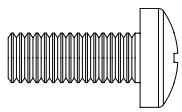
M6 x 16 mm Bolt - Q Qty. 4
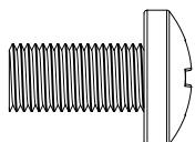
M8 x 16 mm Bolt - R Qty. 4
M4 x 35 mm Bolt - S Qty. 4
M5 x 35 mm Bolt - T Qty. 4
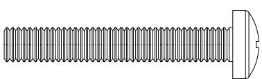
M6 x 40 mm Bolt - U Qty. 4
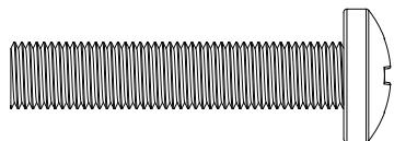
M8 x 40 mm Bolt - V Qty. 4

M4 Lock Washer - W Qty. 4

M5 Lock Washer - X Qty. 4

M6 Lock Washer - Y Qty. 4

M8 Lock Washer - Z Qty. 4
M4/M5 Spacer - AA Qty. 4
M6/M8 Spacer - BB Qty. 4
M4/M5 Washer - CC Qty. 8
M6/M8 Washer - DD Qty. 4
Step 1: Configure the Monitor Brackets
If the hole pattern on the back of your television falls within the vertical reach of the Monitor Brackets (D,E, or F) you do not have to install the Monitor Bracket Extensions (B). If the hole pattern on the back of your television exceeds the vertical reach of the Monitor Brackets, the Monitor Bracket Extension must be used.
NOTE: If the Monitor Extension Brackets (B) are required, both Monitor Bracket Extension Brackets must be installed.
CAUTION: Both threaded studs on each Monitor Bracket Extension (B) must pass through the Monitor Bracket (D, E, or F) to ensure a safe installation.
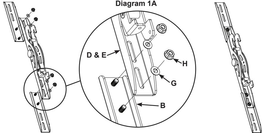
Tilting Monitor Brackets - See Diagram 1A
To install the Monitor Bracket Extensions (B) place the threaded stud portion through the Tilting Monitor Bracket (D,E); then, slide a Nylon Washer (G) onto the threaded stud.
NOTE: The Monitor Bracket Extensions can be adjusted to the correct height.
Secure the Monitor Bracket Extension (B) by threading on, and tightening a Flange Nut (H) onto each threaded stud of the Monitor Bracket Extension (B).
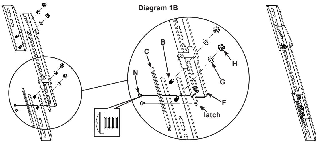
Low Profile Monitor Brackets - See Diagram 1B
To install the Monitor Bracket Extensions (B) place the threaded stud portion through the Low Profile Monitor Bracket (F); then, slide a Nylon Washer (G) onto the threaded stud.
NOTE: The Monitor Bracket Extensions can be adjusted to the correct height.
Secure the Monitor Bracket Extension (B) by threading on, and tightening a Flange Nut (H) onto each threaded stud of the Monitor Bracket Extension.
NOTE: If the latch is within reach from the bottom of the television, the Latch Extension (C) is not required.
The Latch Extension may be adjusted for easy operation on televisions of varying height. Using the 10-32 Screws (N), secure the Latch Extension (C) to the latch on both Low Profile Monitor Brackets (F).
NOTE: If you are using the Low Profile Monitor Brackets (F), proceed directly to Step 4 for televisions with a flat back and Step 5 for televisions with a curved back.
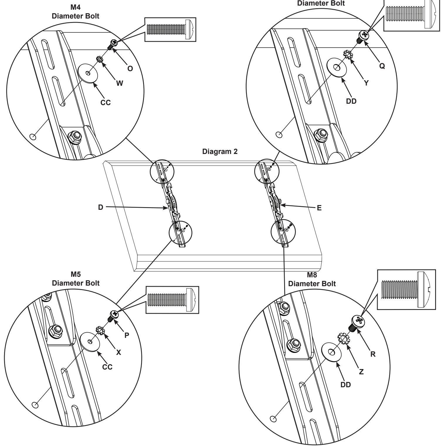
Step 2: Attach Tilting Monitor Brackets to a television with a flat back.
NOTE: For televisions with a curved back, or an obstruction near the threaded insert proceed directly to Step 3.
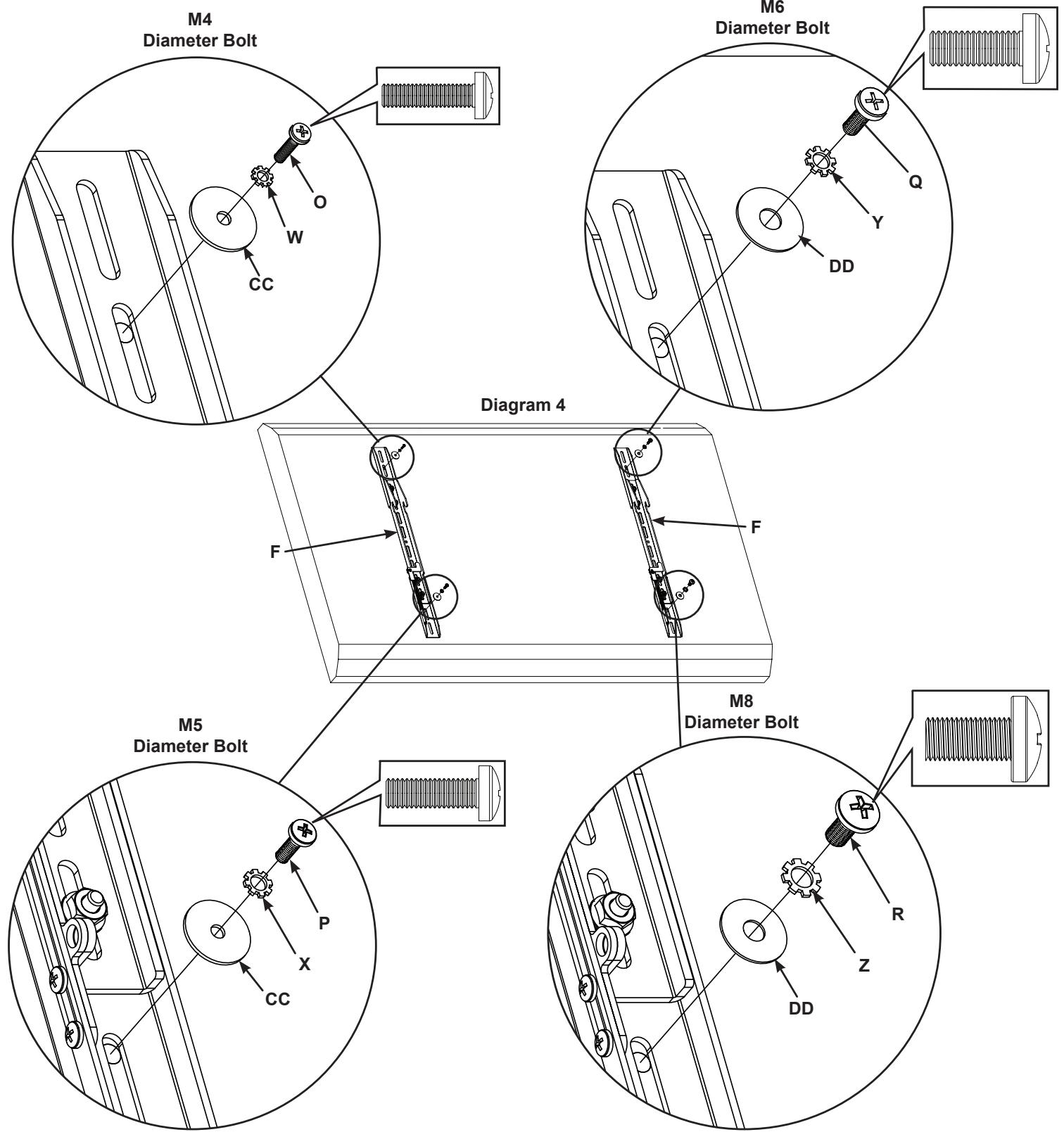
Determine the diameter of the Bolt (O,P,Q,R) your television requires by hand threading them into the threaded insert on the back of the television. If you encounter any resistance, stop immediately.
Once you have determined the correct diameter Bolt (O,P,Q,R) , see the appropriate diagram below, thread the Bolt through the appropriate Lock Washer (W,X,Y,Z), corresponding Washer (CC,DD), Tilting Monitor Bracket (D,E,) or Monitor Bracket Extension (B), and finally into the television.
Make sure the Tilting Monitor Brackets (D,E) are vertically centered and level with each other.
Tighten the Bolts (O,P,Q,R) securing the Tilting Monitor Brackets (D,E) to the television.
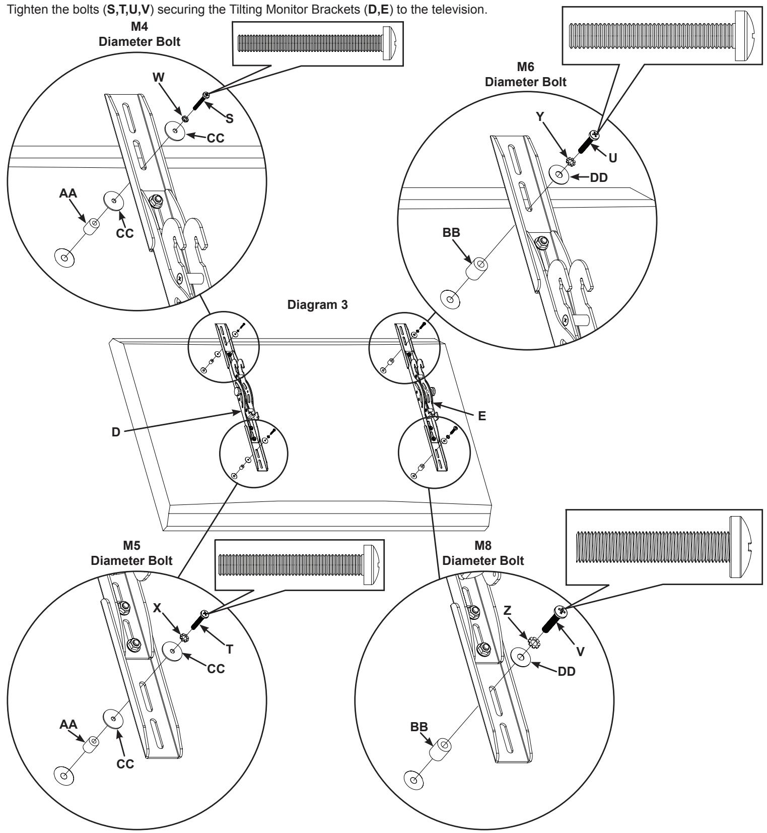
Step 3: Attach Tilting Monitor Brackets to a television with a curved back or an obstruction near the threaded insert.
Note: After Completing Step 3, proceed directly to Step 6.
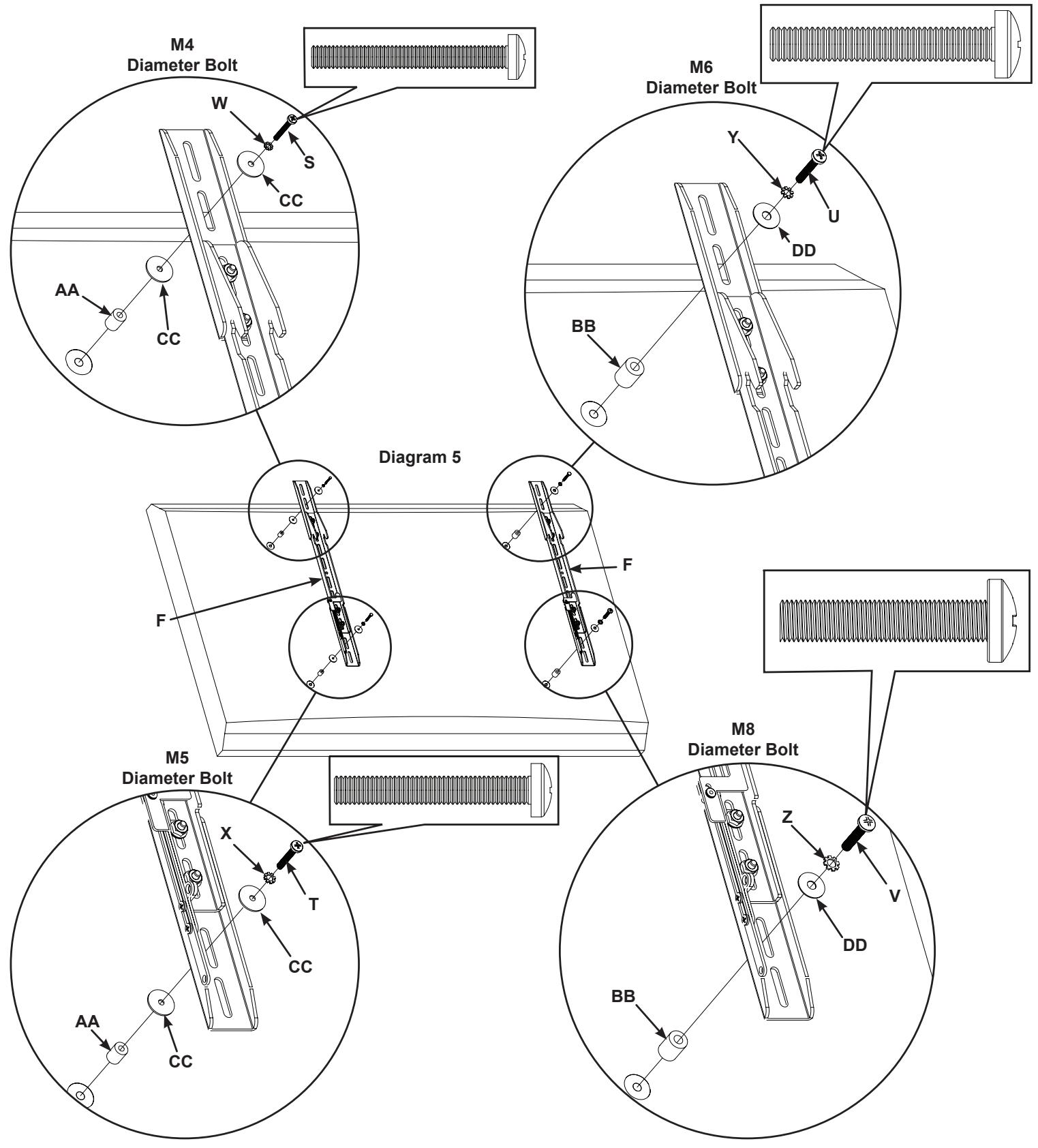
Determine the diameter of the Bolt (S,T,U,V) your television requires by hand threading them into the threaded insert on the back of the television. If you encounter any resistance, stop immediately.
Once you have determined the correct diameter Bolt (S,T,U,V), see the appropriate diagram below, thread the Bolt through the appropriate Lock Washer (W,X,Y,Z), corresponding Washer (CC,DD), Tilting Monitor Bracket (D,E) or Monitor Bracket Extension (B), a second Washer (CC, M4/M5 diameters only), a Spacer (AA,BB) and finally into the television.
Make sure the Tilting Monitor Brackets (D,E) are vertically centered and level with each other.
Tighten the bolts (S,T,U,V) securing the Tilting Monitor Brackets (D,E) to the television.
Step 4: Attach Low Profile Monitor Brackets to a television with a flat back.
NOTE: For televisions with a curved back, or an obstruction near the threaded insert proceed directly to Step 5.
Determine the diameter of the Bolt (O,P,Q,R) your television requires by hand threading them into the threaded insert on the back of the television. If you encounter any resistance, stop immediately.
Once you have determined the correct diameter Bolt (O,P,Q,R) , see the appropriate diagram below, thread the Bolt through the appropriate Lock Washer (W,X,Y,Z), corresponding Washer (CC,DD), Low Profile Monitor Bracket (F) or Monitor Bracket Extension (B), and finally into the television.
Make sure the Low Profile Monitor Brackets (F) are vertically centered and level with each other.
Tighten the Bolts (O,P,Q,R) securing the Low Profile Monitor Brackets (F) to the television.
Step 5: Attach Low Profile Monitor Brackets to a television with a curved back or an obstruction near the threaded insert.
Determine the diameter of the Bolt (S,T,U,V) your television requires by hand threading them into the threaded insert on the back of the television. If you encounter any resistance, stop immediately.
Once you have determined the correct diameter Bolt (S,T,U,V), see the appropriate diagram below, thread the Bolt through the appropriate Lock Washer (W,X,Y,Z), corresponding Washer (CC,DD), Low Profile Monitor Bracket (F) or Monitor Bracket Extension (B), a second Washer (CC, M4/M5 diameters only), a Spacer (AA,BB) and finally into the television.
Make sure the Low Profile Monitor Brackets (F) are vertically centered and level with each other.
Tighten the Bolts (S,T,U,V) securing the Low Profile Monitor Brackets (F) to the television.
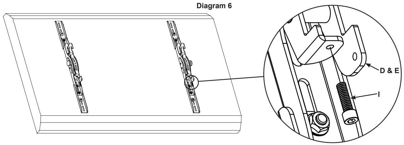
Step 6: Add Safety Bolts (Tilting Monitor Brackets only)
Thread a Safety Bolt (I) into the bottom portion of each Tilting Monitor Bracket (D & E) approximately 1/4'' as shown in Diagram 6.
NOTE: Do not tighten the Safety bolt (I). The Safety Bolt is tightened after the television and Tilting Monitor Brackets (D & E) are attached to the Wall Plate Assembly (A).
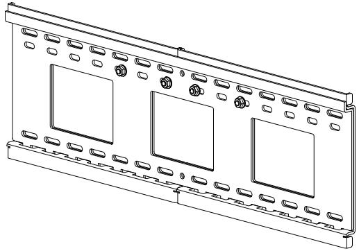
Step 7: Configure Wall Plate Assembly
The Wall Plate Assembly (A) can be adjusted in width from 27^ to 42^ [686 mm to 1067 mm]. Determine how wide you want the Wall Plate Assembly based on the following criteria:
- Width of television (Wall Plate Assembly should be configured so the total width is less than the overall width of your television)
- Width of Hole Pattern on television (Wall Plate Assembly should be wider than the horizontal distance between threaded inserts on the back of your TV by at least 2" [50.8 mm])
- Stud Spacing (Sanus recommends attaching Wall Plate Assembly to three studs for televisions over 125 lbs. [56.7 Kg])
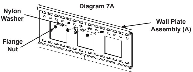
To adjust the width of the Wall Plate Assembly (A):
Remove each Flange Nut and Nylon Washer as shown in Diagram 7A
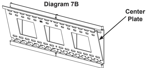
Remove the Center Plate of the Wall Plate Assembly (A) as shown in Diagram 7B.
Seperate the Left and Right Extension of the Wall Plate Assembly (A) and set them to so that their outer edges are equal to the desired width; then, insert the Center Plate so the teeth on its bottom fit into the slots in the Left and Right Extension, making sure that the Threaded Studs fit through the center row on holes in the Center Plate as shown in Diagram 7C.
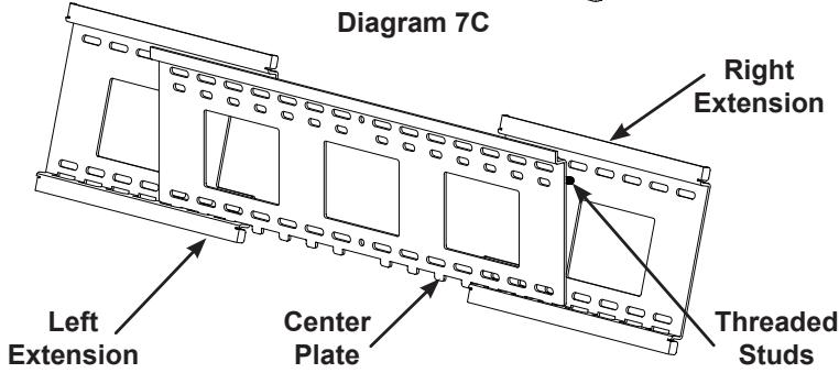
CAUTION: All four Threaded Studs must pass through the Center Plate for the installation to be safe.
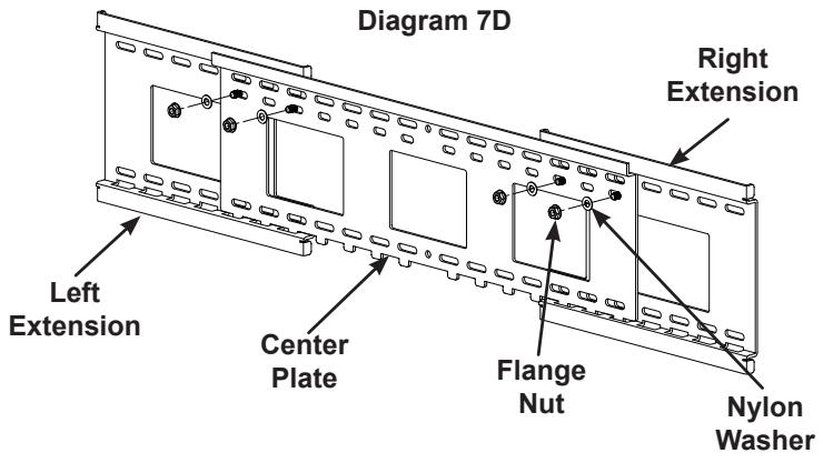
Using the previously removed Flange Nuts and Nylon Washers, secure the Right and Left Extension to the Center Plate as shown in Diagram 7D, and securely tighten the Flange Nuts.
Step 8: Mount the Wall Plate Assembly; Wood Stud, Brick, Solid Concrete, and Concrete Block mounting options are provided.
CAUTION: On all installations, two Lag Bolts (K) must pass through each Wall Plate Extension. Only the fifth and sixth Lag Bolts may pass through the Center Plate (A).
Wood Stud Mounting:
CAUTION: Do not overtighten the Lag Bolts (K). Tighten the Lag Bolts only until the lag Bolt Washer (L) is pulled firmly against the Wall Plate Assembly (A).
NOTE: The Wall Plate Assembly (A) must be mounted on two or three studs at least 12^ [304.8 mm] apart, and three studs are recommended for televisions over 125 lbs [56.7 Kg].
Use a high quality stud sensor to locate two or three adjacent studs; then, using the Wall Plate Assembly (A), as a template, mark a location at each of the studs using the top row of slots on the Wall Plate Assembly and the corresponding slot in the bottom row.
Pre-drill a 2.5'' [63.5 mm] deep into the studs, using a 3/16'' drill bit. Place the Wall Plate Assembly (A) with its flat surface against the wall and the Flange Nuts toward the top; then secure the Wall Plate Assembly using the Lag Bolts (K) and Lag Bolt Washers (L) as shown in Diagram 8A.
Brick, Solid Concrete, and Concrete Block Mounting:
Use the Wall Plate Assembly (A) as a template to mark six locations on the wall. Three in the top row of slots and three more directly below in the bottom row of slots.
CAUTION: Never drill into the mortar between the blocks.
Carefully pre-drill six 2.5'' [63.5 mm] deep holes with a 1/2'' masonry bit.
Insert a Concrete Anchor (M) into each pre-drilled hole so it is flush with the concrete, brick, or concrete block surface, even if there is a layer of drywall or other material in front of the surface.
Place the Wall Plate Assembly (A) with its flat surface against the wall and the Flange Nuts toward the top; then, attach the Wall Plate Assembly to the wall using the six Lag Bolts (K) and Lag Bolt Washers (L) as shown in Diagram 8B.
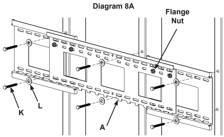
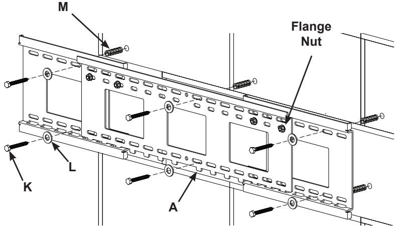
Diagram 8B
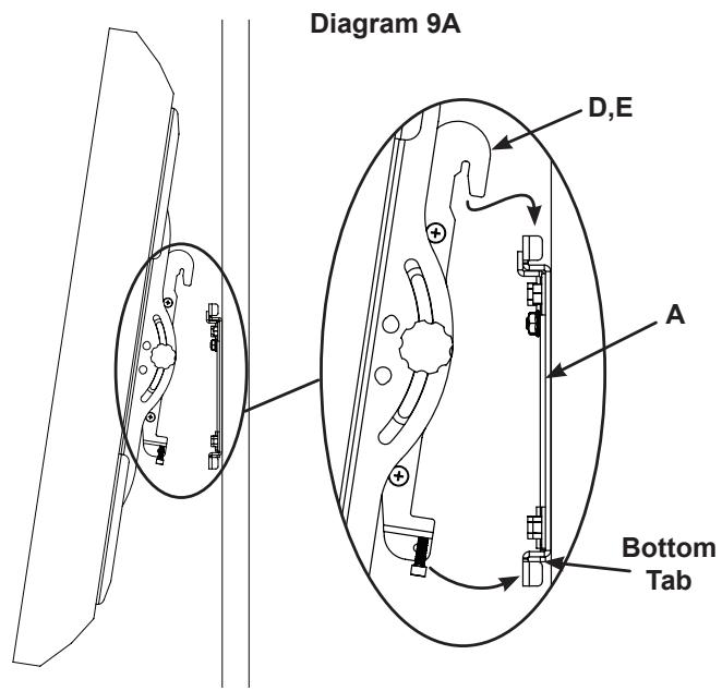
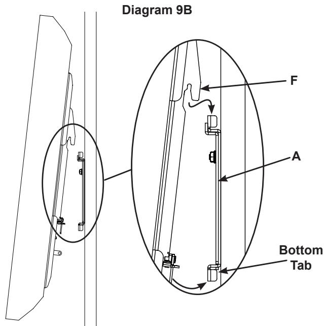
Step 9: Hang the Television onto the Wall Plate
CAUTION: Some televisions may require two people to lift. Sanus is not responsible for personal injury or product damage.
CAUTION: The Monitor Brackets must hang on the left and right extension panels of the Wall Plate Assembly, they can not hang directly on the center plate.
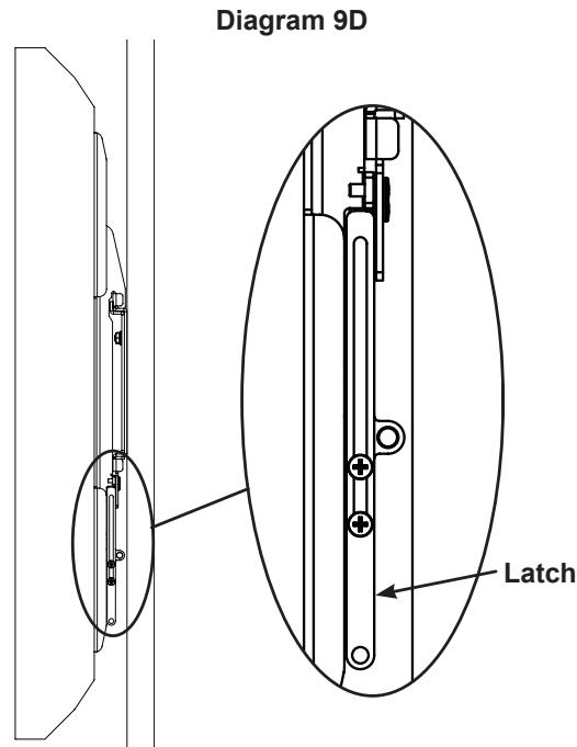
NOTE: For the Low Profile Monitor Bracket, make sure the latch is in the open position.
Hook the Tilting Monitor Brackets (D,E) as shown in Diagram 9A, or the Low Profile Monitor Brackets (F) as shown in Diagram 9B over the top of the Wall Plate Assembly (A); then, let the bottom of the Monitor Brackets rotate in under the bottom of the Wall Plate Assembly.
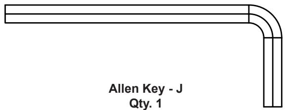
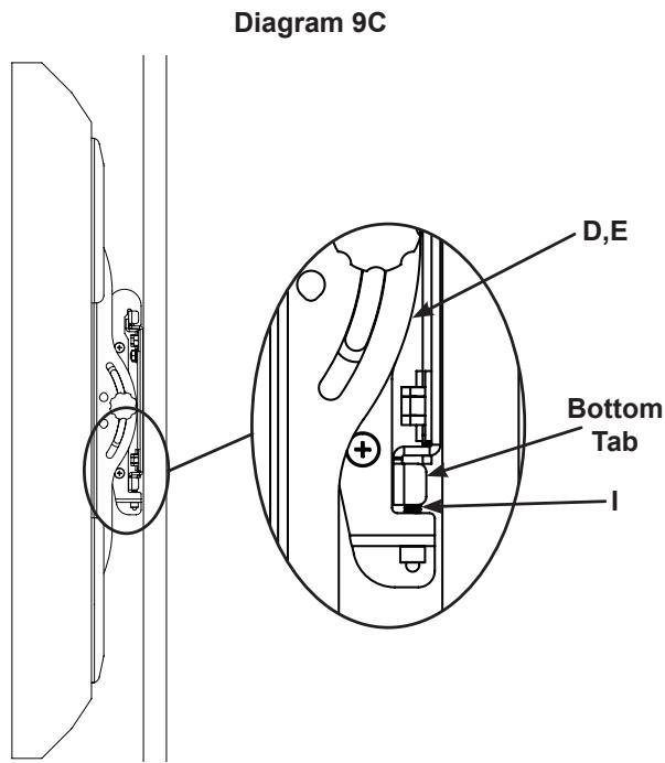
On the Tilting Monitor Brackets (D,E) tighten Safety Bolts (I) with the Allen Key (J) so that they sit behind the bottom tab on the Wall Plate Assembly (A) as shown in Diagram 9C or rotate the Latch downward on the Low Profile Monitor Brackets (F) as shown in Diagram 9D.
On Tilting Monitor Brackets (D,E) only, set tension of the knobs and you are free to adjust your new flat panel television without having to re-tighten the knobs.
SANUS SYSTEMS
Plaque murale - A Qte 1