
PAB 2100 - Power amplifier MB QUART - Free user manual and instructions
Find the device manual for free PAB 2100 MB QUART in PDF.
| Product Type | 2-Channel Power Amplifier |
| Brand | MB QUART |
| Model | PAB 2100 |
| Category | Premium Multichannel Amplifier |
| Number of Channels | 2 |
| Supported Impedance (Stereo) | 4 & 2 ohms |
| Supported Impedance (Bridged Mono) | 4 ohms |
| Input Sensitivity Range | 0.2 V to 6 V |
| Built-in Active Filters | High-Pass (HP), Low-Pass (LP), Full-Range (FULL) |
| Stereo Filter Slope | 12 dB/Oct |
| Mono Filter Slope | 24 dB/Oct |
| LED Indicators | Power (green), Diagnose/Protect (red) |
| Power Supply | 12 V DC (vehicle battery) |
| Current Consumption | Variable based on load; built-in fuse |
| Warranty | 1 year (parts and labor) |
| Available Adjustments | Level (gain), Bass EQ (0 to +9 dB at 45 Hz), X-OVER (HP/LP/FULL), Subsonic (on certain modes) |
| Built-in Protection | Speaker short circuit, DC offset, overheating (trigger at 80°C) |
| Line Outputs (LINE OUT) | Yes, for daisy-chaining |
| Typical Applications | Full-range stereo, bridged mono, bi-amplification (high-pass + low-pass) |
| General Maintenance | Clean with a dry cloth; avoid moisture |
| Usage Safety | Do not use below specified minimum impedance |
Frequently Asked Questions - PAB 2100 MB QUART
User questions about PAB 2100 MB QUART
0 question about this device. Answer the ones you know or ask your own.
Ask a new question about this device
Download the instructions for your Power amplifier in PDF format for free! Find your manual PAB 2100 - MB QUART and take your electronic device back in hand. On this page are published all the documents necessary for the use of your device. PAB 2100 by MB QUART.
USER MANUAL PAB 2100 MB QUART
74847 Obrigheim, Germany
Phone +49 (0) 62 61 - 6 38-0
FAXX +49 (0) 62 61 - 6 38-129
E-Mail info@mbquart.de
Website www.mbquart.de

Installation & Operation
Einbau und Betrieb
By purchasing an amplifier from MB QUART, you have decided on a product of the highest technical quality. MB QUART wishes you great enjoyment with your amplifier. Should you have any questions about this system or other MB QUART products, please call us personally or send us an e-mail at info@mbquart.de
| WARRANTY | 2 |
| GENERAL INSTALLATION NOTES | |
| System design | 3 |
| Installation | 3 |
| AMPLIFIER FEATURE DESCRIPTION | |
| PAB 2100 2-Channel Amplifier | 4 |
| PAB 4100 4-Channel Amplifier | 4 |
| PAB 5400 5-Channel Amplifier | 5 |
| PAB 1200.1 D Mono Amplifier | 5 |
| AMPLIFIER APPLICATIONS | |
| PAB 2100 2-Channel Amplifier | |
| Full range stereo | 6 |
| Full range mono | 6 |
| Stereo high pass with mono low-pass in a 2 way active, or bi-amplified system | 7 |
| PAB 4100 4-Channel Amplifier | |
| 4 channel full range system | 8 |
| 2 or 3 channel full range system | 8 |
| 2 way active, or bi-amplified system with mono bass | 9 |
| 2 way active, or bi-amplified system with mono bass, and faded highs/ lows | 9 |
| Front/rear high pass, using a 2 channel amplifier for mono sub bass | 10 |
| PAB 5400 5-Channel Amplifier | |
| 5 channel discrete, one being mono low pass | 11 |
| 3 or 4 channel discrete, one being mono low pass | 11 |
| 3 way active, with mono bass | 12 |
| Front/rear high pass, with constant sub bass | 12 |
| PAB 1200.1 D Mono Amplifier | |
| Basic application | 13 |
| AFTER INSTALLATION | |
| Setting up systems after installation for best performance | 14 |
| Troubleshooting a system | 14-15 |
| TECHNICAL DATA | 86 |
Warranty
As the manufacturer of MB QUART car audio products, Maxxsonics USA Inc. and Maxxsonics Europe GmbH warrants to the original consumer purchaser the amplifier to be free from defects in material and workmanship for one (1) year from date of purchase.
This product meets the current EU minimum warranty requirements, if purchased in countries of the EU.
To ensure your warranty policy keep your original receipt proofing the date of purchase.
All other part and accessories of the system are warranted to be free from defects in material and workmanship for one (1) year from date of purchase. Maxxsonics will repair or replace at it's option and free of charge during the warranty period, any system component that proves defective in materials and workmanship under normal installation, use and service provided that the product is returned to the authorised MB QUART dealer from where it was purchased.
A photo copy of the original receipt must accompany the product being returned. In the absence of the above, the warranty is one (1) year from date of manufacture.
Any damage to the product as a result of misuse, abuse, accident, incorrect wiring, improper installation, alteration of date code or bar code labels, revolution, natural disaster, or any sneaky stuff because someone messed up, repair or alteration out side of our factory or authorised service centers and any thing else you have done that you should not have done is not covered.
This warranty is limited to defective parts and specifically excludes any incidental or consequential damages connected therewith. This warranty is not to be construed as an insurance policy.
Warranty on installation labor, removal, re-installation and freight charges are not the responsibility of Maxxsonics USA Inc. or Maxxsonics Europe GmbH.
System design
The success of any car stereo system relies on several factors, such as the system design, execution of the installation, and system setup. This section is intended to assist the installer by offering several tips and hints about good installation practice. Please remember that any system is only as good as its weakest link.
Determine the system format, e.g., single amplifier, active, front/rear and so on. Then choose the amplifier power points according to personal taste. Please remember that higher power systems are not necessarily useful purely for high sound pressure levels, but also to establish a headroom capability, to reproduce musical peaks cleanly without distortion. Lower power amplifiers will clip earlier than their more powerful cousins, and cause loudspeaker failure when overdriven, due to the harmonics generated by a clipped signal, thus overheating voice coils.
Choose loudspeaker and amplifier mounting locations. Loudspeaker location is always a matter of compromise between space and sound stage imaging. Amplifiers should be mounted with the fins running vertically for best convection cooling, to minimize overheating.
Purchase the best quality RCA cables you can afford, for reliability and less engine noise interference in the audio system.
Installation
General:
Mount the amplifier/s in the chosen location.
Run the wiring so that RCA cables are at least 18^ away from power and speaker cables. Keep RCA cables away from electrical devices in the vehicle that can cause electrical noise, such as fuel pumps.
Power and ground connections:
Use a sufficient gauge power cable, at least #8 per amplifier. In a multi amplifier system, it is advisable to mount a large enough fuse right at the battery, and run a master +12 volt power cable to a fused distribution block near the amplifiers. It is then a simple matter to connect the +12 volt terminal of each amplifier to the distribution block.
Ground each amplifier with as short a ground lead, again at least #8 gauge, directly to the vehicle chassis. Use a ground distribution block, if you wish, but it is extremely important to keep the main ground lead from this distribution block to the chassis as short as possible, not more than 12". The ground connection integrity to the chassis is very important, and the best way to achieve a good, solid electrical and mechanical contact is to use a large round crimp lug, crimped and soldered to the ground cable. The next step is to scrape the paint off the vehicle chassis, slightly larger than the ground lug, at the connection point. Drill a clearance hole in the chassis, the same size as the lug hole, and use a bolt, spring washer and nut to securely fasten the ground lug. Use petroleum jelly to coat the bolt/lug connection, to prevent oxidization with time.
Tip: Use the same approach when installing head units, equalizers or any audio equipment for that matter - run short individual grounds from each piece directly to the vehicle chassis, to minimize ground loops and system noise.
All power, ground and speaker connections should be crimped and soldered for reliability. Make sure that none of the cable insulation can chafe against exposed metal in the vehicle, causing short circuits to the chassis.
Safe connection sequence:
After all cables are run, connect speaker wires to the speakers and amplifiers, then run and plug in RCA cables. Next, connect all power grounds and remote turn on leads. Now connect all +12 volt cables to the amplifier/s and distribution blocks and fuse holders. Finally, connect the main +12 volt cable to the battery, with the main fuse removed, and we are almost ready to power up the system.
Power up the system:
The following procedure may seem like overkill, but there is nothing more frustrating than turning on a system for the first time, and it does not work properly immediately.
First, make sure the head unit is off, and turn all level controls to minimum (anticlockwise), including the head unit volume control. Set all equalizers to 0 dB (no boost), and all crossover frequency controls at approximate frequencies, as recommended by the loudspeaker manufacturer. Set all input selector and crossover switches as required for the application.
Remove all amplifier fuses, and insert the main fuse at the battery. If the fuse does not blow, you can insert the fuse in one of the amplifiers, and we are ready to turn on the system.
Turn the head unit on, insert a CD, or select a radio station, and increase the head unit volume control. If the system sounds fine, turn off the head unit, and install fuses in the remaining amplifiers, one by one, till the complete system is powered up and functioning properly.
Premium Multi-Channel Amplifiers
- Each model is capable of 4 &t 2 ohms stereo per channel, or 4 ohms mono bridged operation.
- Tri-Mode operation with any stereo pair of amplifier channels is possible, as with all bridgeable amplifiers.
- The input sensitivities for rated output powers are variable from 0.2 volt to 6 volt.
- All crossovers are fully variable in their respective ranges.
- Crossover filter slopes are 12 dB/octave for stereo filters, and 24 dB/octave for mono filters.
-
A POWER LED indicates the powered "up" and turned "on" condition.
-
All MB QUART Premium amplifiers feature a comprehensive diagnostic system, with speaker lead short circuit, and amplifier DC faults indicated by the DIAGNOSTIC, or PROTECT LED.
CAUTION:
DO NOT OPERATE ANY AMPLIFIER BELOW THE INTENDED IMPEDANCE. YOU WILL CAUSE DAMAGE TO THE AMPLIFIER THAT WILL NOT BE COVERED UNDER THE WARRANTY PRINTED IN THE BACK OF THE MANUAL.
Multi-Channel amps: 4 & 2 ohms stereo, 4 ohms mono bridged
PAB 2100 2-Channel Amplifier
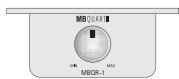
The X-OVER slide switch selects the internal crossover functions:
- The input signal is routed directly to the LINE OUT RCA jacks, regardless of the X-OVER setting simplifying daisy chaining of amplifier.
HP: Selects the built in HIGH PASS filter, variable from 10 Hz to 150 Hz. - FULL: Bypasses all crossovers for full frequency range operation.
- LP: Selects the built in LOW PASS filter, variable from 30 Hz to 150 Hz.
Note that the LOW PASS signal is MONO.
- In the LP position, the HIGH PASS filter acts as a subsonic filter.
- When the LP mode is selected, a 0 to +9 dB, at 45Hz , BASS EQ is also switched
PAB 4100 4-Channel Amplifier
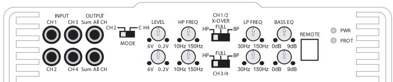
INPUT MODE slide switch:
- In the CH2 position, ALL four amplifier inputs are selected from the CH1/CH2 RCA jacks.
- In the 4CH position, channel pair 1&t2 receive input signal from RCA jacks CH1 and CH2, and channel pair 3&t4 receive input signal from RCA jacks CH3 and CH4.
The AMPLIFIER CH 1/2CH X-OVER slide switch selects the input signal for channel pair 1Et2:
- HP: Selects the built in HIGH PASS filter, variable from 10 Hz to 150 Hz.
- FULL: Bypasses all crossovers for full frequency range operation.
- BP: Selects the built in LOW PASS filter, variable from 30 Hz to 150 Hz.
Note that the LOW PASS signal is MONO.
- In the BP position, the HIGH PASS filter acts as a subsonic filter.
- When the BP mode is selected, a 0 to +9 dB, at 45Hz , BASS EQ is also switched in.
The AMPLIFIER CH 3/CH 4 X-OVER slide switch selects the input signal for channel pair 3&t4:
- Hi: Selects the built in HIGH PASS filter, variable from 10 Hz to 150 Hz.
- FULL: Bypasses all crossovers for full frequency range operation.
- BP: Selects the built in LOW PASS filter, variable from 30 Hz to 150 Hz.
Note that the LOW PASS signal is MONO.
- In the BP position, the HIGH PASS filter acts as a subsonic filter.
- When the BP mode is selected, a 0 to +9 dB, at 45Hz , BASS EQ is also switched in.
- Full range signal from channels 1/2 inputs are routed to the Line OUT RCA jacks, regardless of the setting of the X-OVER switches.
- The REMOTE jack enables dash mount level control of the LOW PASS signal, CH3/4 only.
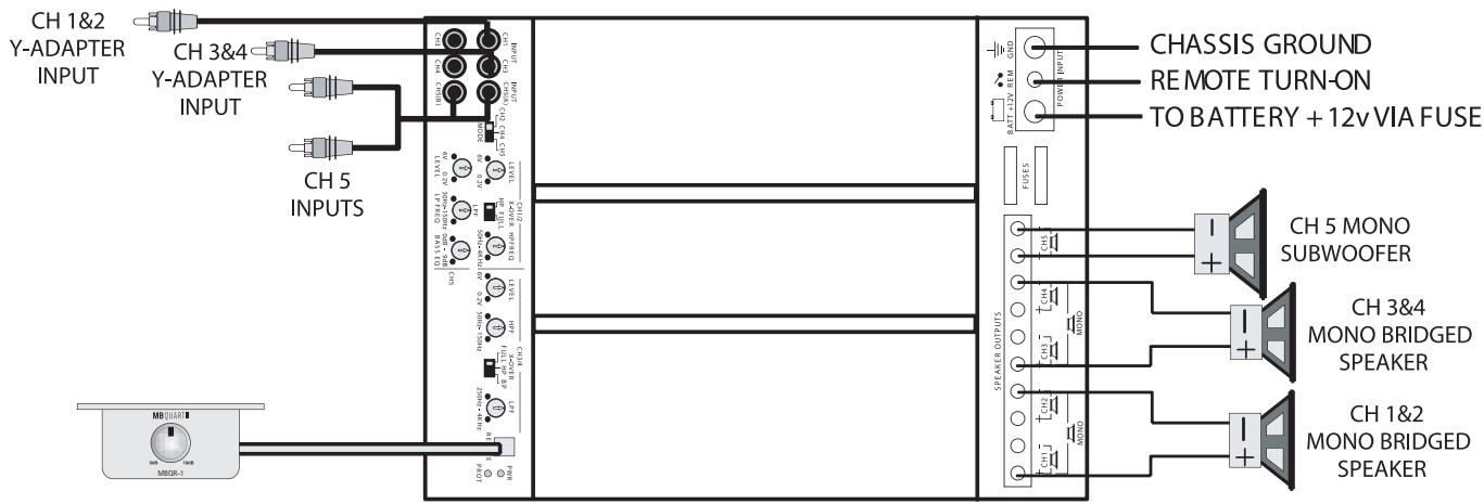
PAB 5400 5-Channel Amplifier
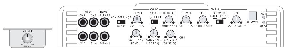
The PAB 5400 has three sets of inputs:
Line inputs on RCA jacks for channel pairs 1&t2, 3&t4, and MONO channel 5. These inputs can be used in various combinations, to suit the application, depending on the settings of the INPUT MODE switch, and the X-OVER switches for channels 1&t2, and channels 3&t4, respectively.
INPUT MODE slide switch:
- In the CH2 position, ALL five amplifier inputs are selected from the CH1/CH2 RCA jacks. Channel 5 receives a mono mixed signal.
- In the 4CH position, channel pair 1&t2 receive input signal from RCA jacks CH1 and CH2, and channel pair 3&t4 receive input signal from RCA jacks CH3 and CH4. A mono mixed signal from these four RCA jacks are also fed to channel 5.
- When 5CH DISCRETE is selected, each channel receives an input signal from its respective input RCA jack. Channel 5 has two jacks on its LINE INPUT, which are summed together.
CH1/2 X-OVER slide switch:
- FULL: Sets this pair to full range operation.
- HP: Selects the HIGH PASS filter, variable from 50 Hz to 4 KHz.
CH3/4 X-OVER slide switch:
- FULL: Sets this pair to full range operation.
- B.P.: In this mode, the HIGH PASS and a LOW PASS filter, both fully variable from 50Hz to 4KHz , are selected to form a BANDPASS crossover filter.
- HP: Selects the HIGH PASS filter, variable from 50 Hz to 4 KHz.
CH5:
- The channel 5 functions were chosen to be very specific to mono bass operation, and not switchable:
- The LOW PASS filter has a variable range from 30Hz to 150Hz .
- The BASS EQ gives a bass boost, 0 to +9 dB, at 45 Hz.
Premium Mono Amplifier
- The Premium Mono Amplifier is capable of 4, 2 &t 1 Ohm loads.
- The input sensitivities for rated output powers are variable from 0.2 volt to 9 volts.
- All crossovers are fully variable in their respective ranges.
- Crossover filter slopes are 24 dB/octave for mono filters.
- A POWER LED indicates the powered up and turned on condition.
CAUTION:
DO NOT OPERATE ANY AMPLIFIER BELOW THE INTENDED IMPEDANCE. YOU WILL CAUSE DAMAGE TO THE AMPLIFIER THAT WILL NOT BE COVERED UNDER THE WARRANTY PRINTED IN THE BACK OF THE MANUAL.
Mono amps: 4, 2 &t 1 ohms
PAB 1200.1 D Mono Amplifier
The 1 channel mono amplifiers are capable of 4, 2 &t 1 ohm loads and can be used in any of the "bi-amplifier" systems described in the 2 and 4 channel directions.
The line input signal is routed directly to the line output RCA's jacks regardless of the crossover settings.
The REMOTE jack allows the addition of the Bass Remote module which controls the BASS EQ signal.
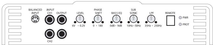
- SUBSONIC allows control from 10 Hz to 35Hz
- BASS EQ allows control from 0dB to 9 dB
- LOW PASS allows control from 35Hz to 250Hz
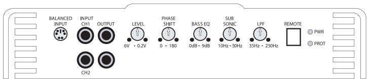
- PHASE shift allows 0 degrees to 180 degrees
- LEVEL: allows you to match the amplifier input level (gain) to the Radio/CD player output level.
- POWER: indicates that the amp has power, ground and remote turn-on input via a green L.E.D.
- PROTECT: indicates that the amplifier has detected a fault and will not operate. There are several possible problems that can cause the amplifier to go into the protect mode. See the trouble shooting guide in the back of the manual for details.
- BALANCED INPUT: Accepts line level balanced input from 0.4v to 18v.
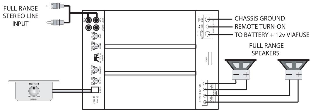
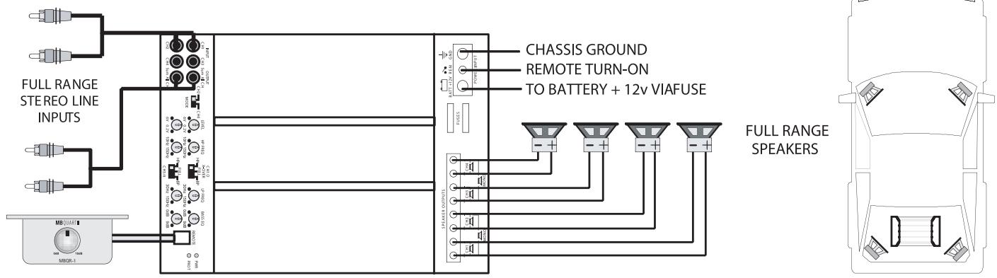
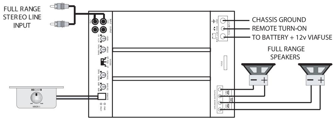
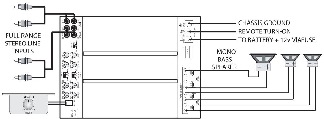
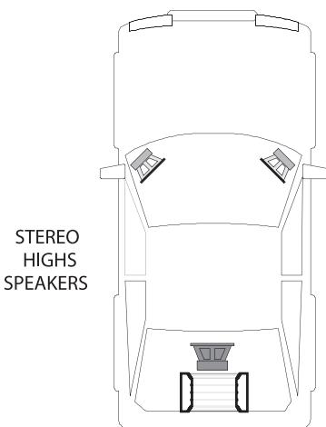
Full range stereo
This is the most basic application for the Premium Series 2 channel amplifiers.
- Interconnect cable checklist:
Connect the LINE INPUTS to the Radio/CD with good quality RCA cables.
- Crossover Switch:
The X-OVER switch must be in the FULL position.
- Crossover frequency control checklist:
N/A for full range operation.
- Line Level:
Refer to the section "Setting up systems after installation for best performance"
- Bass Remote Module:
Plug in the Bass Remote Module to the amplifier "REMOTE" jack.
NOTE:
Minimum final loudspeaker impedances:
4 & 2 Ohms stereo mode or 4-Ohms mono mode
This amplifier will not do 1 Ohm stereo or 2/1 Ohm mono operation.
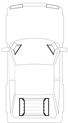
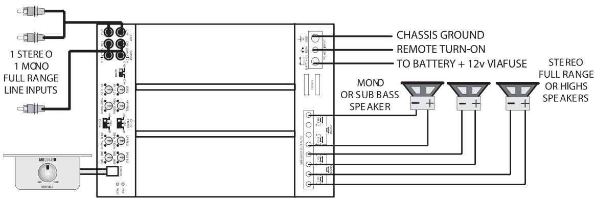
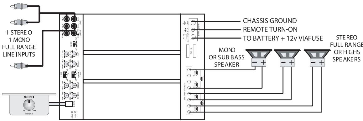
Full range mono
This application illustrates the basic mono bridging method for all MB QUART amplifiers.
Interconnect cable checklist:
A MONO signal source is required, such as would be available from the mono sub bass output of an active crossover, whether stand alone, or built into a head unit or equalizer. Important: Do not be tempted to connect the hot, or positive outputs, from any source together to obtain a mono signal, as this could very well damage the output stage of that source.
It is necessary to feed the SAME signal to both left and right inputs via a Y-adapter RCA cable. Connect the mono speaker positive terminal to the LEFT + , and its negative terminal to RIGHT - .
Switch setting checklist:
The AMPLIFIER X-OVER switch must be in the FULL position.
Crossover frequency control setting checklist:
N/A for full range operation.
TIP: If you are using the mono sub bass output of an active crossover, there is nothing wrong with switching in the low pass filter in these amplifiers for a steeper low pass rolloff.
Minimum final loudspeaker impedance: 4 ohm mono
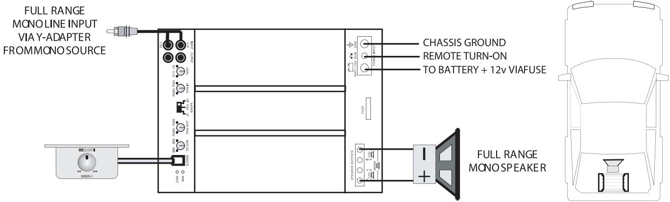
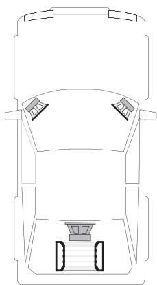
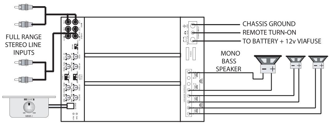
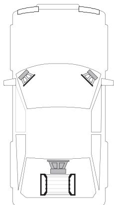
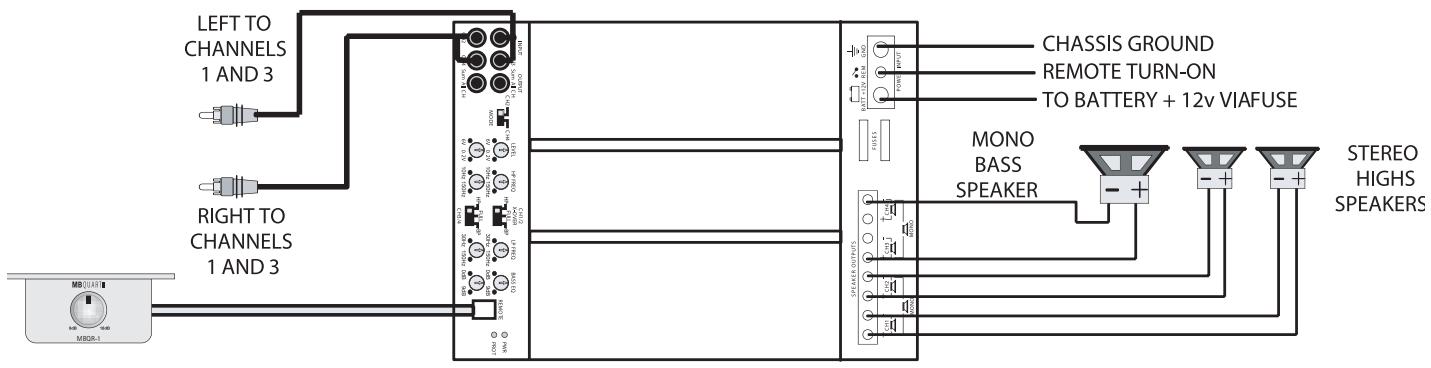
Stereo high pass with mono low-pass in a 2 way active, or bi-amplified system
In this application we will use a 2 channel amplifier for the high frequencies, and a second one for the low frequencies, or mono sub bass. Please consult the speaker specifications to determine maximum amplifier power requirements.
Interconnect cable checklist:
Connect the inputs of the highs amplifier to a Radio/CD with good quality RCA cables. Connect the LINE OUT of the highs amplifier to the inputs of the bass amplifier with a stereo RCA to RCA cable.
Mono bass woofer wiring:
Connect the mono speaker positive terminal to the LEFT +, and its negative terminal to RIGHT -.
Switch setting checklist:
- Highs amplifier: X-OVER switch in the HP position.
- Lows amplifier: X-OVER switch in the LP/BP position.
Crossover frequency control checklist:
Highs amplifier:
- HI PASS: 100 Hz
- LOW PASS: N/A
Lows amplifier:
- HI PASS (Subsonic filter): 10 Hz to 40 Hz
- LOW PASS: 100 Hz
Please note that these frequency points are suggestions only. Refer to the loudspeaker manufacturer specifications and the section "Setting up systems after installation for best performance"
Level control checklist:
Refer to the section "Setting up systems after installation for best performance"
Minimum final loudspeaker impedances:
- 2 ohm per channel stereo.
- 4 ohm mono bridged.
4 channel full range system
Here we show how to use the 4 channel amplifiers as straightforward discrete 4 channel full range units.
Interconnect cable checklist:
Connect the four inputs of the amplifier to a Radio/CD with quality RCA cables.
Switch setting checklist:
- 1/2CH X-OVER: FULL
- 3/4CH X-OVER: FULL
Crossover frequency control checklist:
Channels 1/2: Channels 3/4:
- HI PASS: N/A - HI PASS: N/A
- LOW PASS: N/A - LOW PASS: N/A
Level control checklist:
Refer to the section "Setting up systems after installation for best performance"
Minimum final loudspeaker impedances: 2 ohm per channel
2 or 3 channel full range system
Here we show how to use the 4 channel amplifiers as full range 2 or 3 channel units by taking advantage of the mono bridging capability of all MB QUART amplifiers.
The following example shows how to create a 3 channel system by mono bridging channel pair 3/4 . In order to create a 2 channel system, simply follow the example to also mono bridge channel pair 1/2 .
Interconnect cable checklist:
- Connect the inputs of channel pair 1/2 to a suitable stereo source, e.g. a head unit with good quality RCA cables.
- A MONO signal source is required to bridge channel pair 3/4 , such as would be available from the mono sub bass output of an active crossover, whether standalone, or built into a head unit or equalizer. Important: Do not be tempted to connect the hot, or positive outputs, from any source together to obtain a mono signal, as this could very well damage the output stage of that source.
- It is necessary to feed the SAME signal to both left and right inputs via a Y-adapter RCA cable.
- Connect the mono speaker positive terminal to the LEFT +, and its negative terminal to RIGHT - as shown.
Switch setting checklist:
- 1/2CH X-OVER: FULL
- 3/4CH X-OVER: FULL
Crossover frequency control checklist:
Channels 1/2: Channels 3/4:
- HI PASS: N/A - HI PASS: N/A
- LOW PASS: N/A - LOW PASS: N/A
Tip: If you are using the mono sub bass output of an active crossover, there is nothing wrong with switching in the low pass filter in these amplifiers for a steeper low pass rolloff.
Level control checklist:
Refer to the section "Setting up systems after installation for best performance"
Minimum final loudspeaker impedances:
- 2 ohm per channel in stereo mode.
- 4 ohm mono bridged.
2 way active, or bi-amplified system with mono bass
This application shows how easily a 2 way active system can be implemented using a Premium 4 channel amplifier. Channels 1 and 2 will be used for highs, and channels 3 and 4 for mono bass.
Interconnect cable checklist:
We need to feed the same signal to both sets of channels, so must use 2 Y-adapters, one to feed the LEFT signal to channels 1 and 3, and the right signal to channels 2 and 4, as shown.
Mono bass woofer wiring:
Connect the mono speaker positive terminal to the LEFT + , and its negative terminal to RIGHT -.
Switch setting checklist:
- 1/2CH X-OVER: HI
- 3/4CH X-OVER: LP/BP
Crossover frequency control checklist:
Channels 1/2:
Channels 3/4:
-
HI PASS: 100 Hz
-
HI PASS (subsonic): 20 Hz
-
LOW PASS: N/A
-
LOW PASS: 100 Hz
Please note that these frequency points are suggestions only. Refer to the loudspeaker manufacturer specifications and the section "Setting up systems after installation for best performance"
Level control checklist:
Refer to the section "Setting up systems after installation for best performance"
Minimum final loudspeaker impedances:
- 2 ohm per channel in stereo mode
- 4 ohm mono bridged
2 way active, or bi-amplified system with mono bass, and faded highs/ lows
Here we present a variation of the previous system. Since this is a 2 way system, we can use the front outputs from a head unit to drive the highs, and the rear output to drive the bass. This method allows the listener to easily adjust the relative levels of bass to highs, with the front to rear fade on the head unit.
Channels 1 and 2 will be used for highs, and channels 3 and 4 for mono bass.
Interconnect cable checklist:
- Use good quality RCA leads to connect the inputs of the amplifier to the source as shown.
- Follow the instructions as per the previous system for switch and crossover settings.

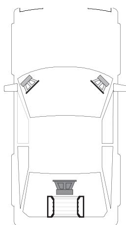
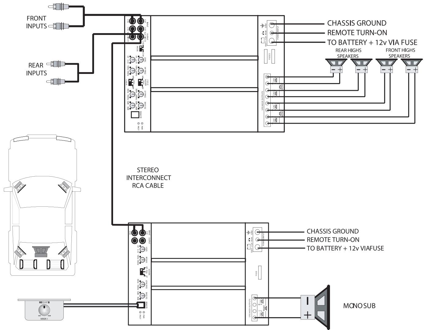
Front/rear high pass, using a 2 channel amplifier for mono sub bass
The combination of a 2 and a 4 channel amplifier, utilizing their built in crossovers, makes it a snap to put together a full system with front and rear highs, with mono sub bass.
Interconnect cable checklist:
- Using good quality RCA cables, feed the front and rear outputs of a head unit to the inputs of the 4 channel amplifier as shown.
- Also connect the LINE OUT of the 4 channel amplifier to the LINE INPUT of the 2 channel amplifier as shown.
Mono bass woofer wiring:
Connect the mono speaker positive terminal to the LEFT +, and its negative terminal to RIGHT -.
Switch setting checklist:
4 channel highs amplifier:
- 1/2CH X-OVER: HI
- 3/4CH X-OVER: HI
2 channel bass amplifier:
- X-OVER switch: LP/BP
Crossover frequency control checklist:
4 channel highs amplifier:
Channels 1/2:
- HI PASS: 100 Hz
- LOW PASS: N/A
Channels 3/4:
- HI PASS: 100 Hz
- LOW PASS: N/A
2 channel bass amplifier:
- HI PASS (Subsonic filter): 10 Hz to 40 Hz
- LOW PASS: 100Hz
Please note that these frequency points are suggestions only. Refer to the loudspeaker manufacturer specifications and the section "Setting up systems after installation for best performance"
Level control checklist:
Refer to the section "Setting up systems after installation for best performance"
Minimum final loudspeaker impedances:
- 2 ohm per channel in stereo mode
- 4 ohm mono bridged
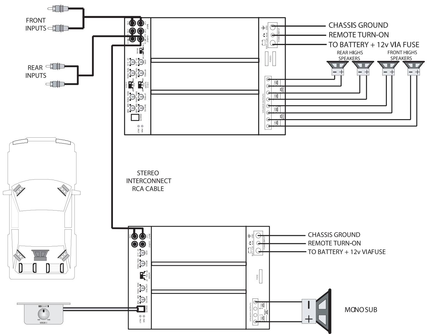
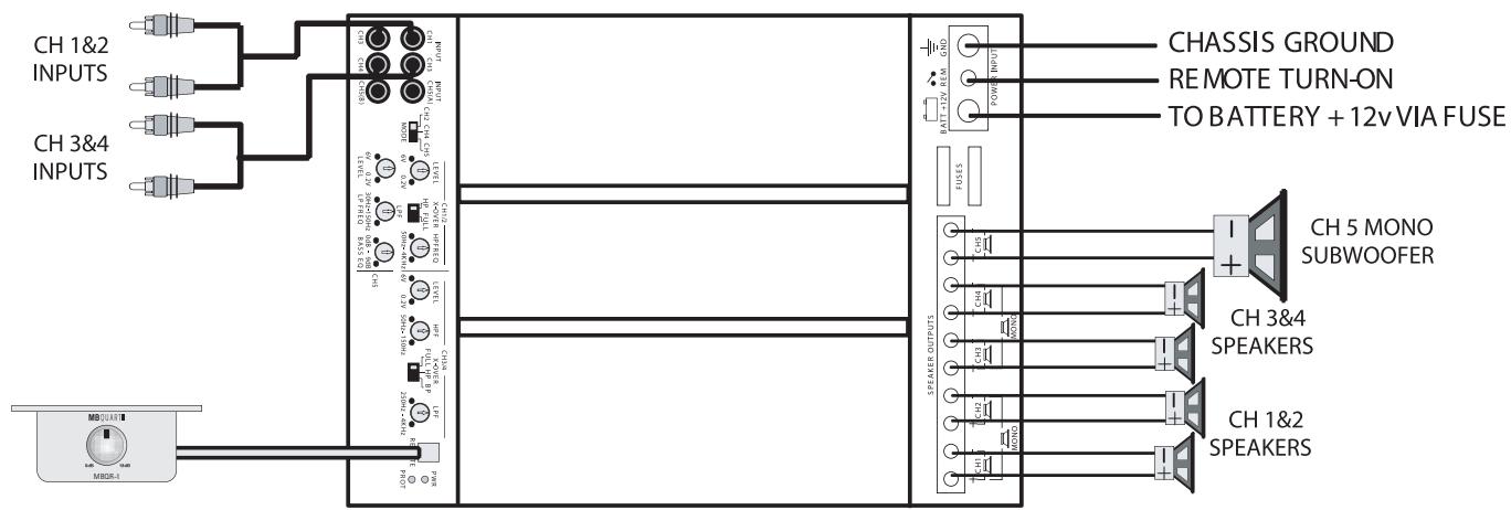
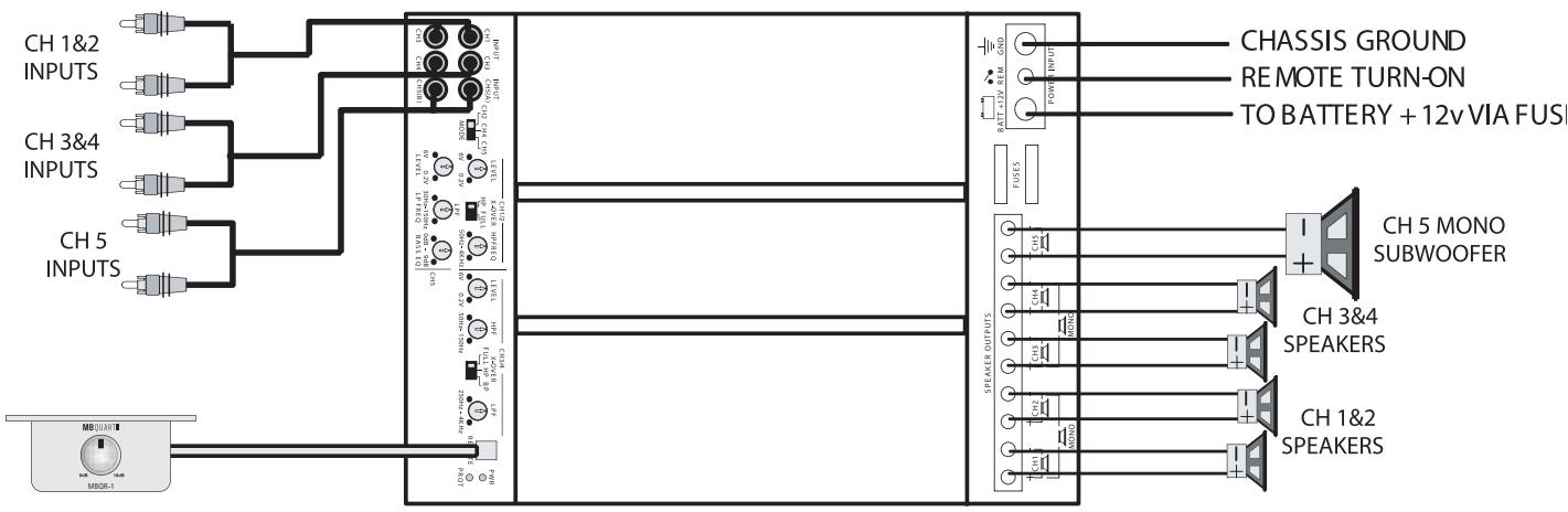
5 channel discrete, one being mono low pass
You can use this configuration simply as 4 discrete full range channels, with a 5th low pass channel. All of the crossovers are bypassed, except the LOW PASS on channel 5. The 5 channels can also be utilized with an outboard active crossover, or with crossovers in head units or equalizers.
Interconnect cable checklist:
Connect channel 1&2 inputs to the front output, channels 3&4 to the rear output, and channel 5 to the mono subwoofer output of a head unit or in dash equalizer. The LOW PASS filter on channel 5 will be in tandem with that of the source. You can either set it to the same frequency for a steeper rolloff, or set it to a higher frequency to minimize its effect. By the same reasoning, you could switch channels 1,2,3&4 high pass crossovers in for steeper high pass slopes.
Switch setting checklist:
- INPUT MODE: 5CH DISCRETE
- CH 1/2 X-OVER: FULL
- CH 3/4 X-OVER: FULL
Crossover frequency control checklist:
- CH 1/2 HIGH PASS: N/A
- CH 3/4 HIGH PASS: N/A
- CH 3/4 LOW PASS: N/A
- CH 5 LOW PASS: 100Hz
Please note that these frequency points are suggestions only. Refer to the loudspeaker manufacturer specifications and the section "Setting up systems after installation for best performance"
Level control checklist:
Refer to the section "Setting up systems after installation for best performance"
Minimum final loudspeaker impedances: 2 ohm per channel
3 or 4 channel discrete, one being mono low pass
We will use the same basic setup as above to illustrate a 3 channel arrangement, by mono bridging the stereo channel pairs 1Et2, 3Et4. For a 4 channel setup, mono bridge only one set.
Interconnect cable checklist:
-
Use 2 Y-adapters RCA cables, one for channels 1&t2, and the second for channels 3&t4, to create 2 inputs for channels 1,2,3&t4 only, as shown.
-
Connect the positive terminal of channels 1&2 mono speaker to channel 1+ , and its negative terminal to channel 2-. Connect the positive terminal of channels 3&4 mono speaker to channel 3+ , and its negative terminal to channel 4-.
- Channel 5 is a true single channel, and as such is not bridgeable.
Minimum final loudspeaker impedances:
- 2 ohm per channel in stereo mode
- 4 ohm per mono bridged pair
- 2 ohm on channel 5
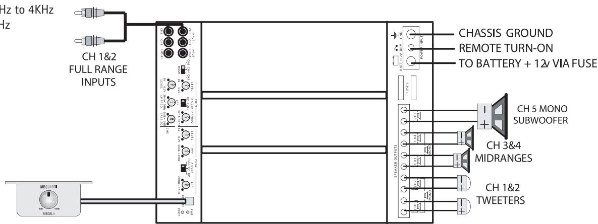
3 way active, with mono bass
The PAB 5400 5 channel amplifier contains all the functions necessary to set up a completely self-contained 3 way active crossover system.
Interconnect cable checklist:
Use good quality RCA cables to connect the inputs of channels 1&2 to the full range outputs of the source.
Switch setting checklist:
- INPUT MODE: CH2
- CH 1/2 X-OVER: HP
-CH3/4X-OVER:BP
Crossover frequency control checklist:
- CH 1/2 HIGH PASS: 1KHz to 4KHz
- CH 3/4 HIGH PASS: 100 Hz
- CH 3/4 LOW PASS: 1KHz to 4KHz
- CH 5 LOW PASS: 100Hz
Note that the HIGH and LOW PASS controls of channels 3εt4 act as the bandpass controls.
Please note that these frequency points are suggestions only. Refer to the loudspeaker manufacturer specifications and the section "Setting up systems after installation for best performance"
Level control checklist:
Refer to the section "Setting up systems after installation for best performance"
Minimum final loudspeaker impedances: 2 ohm per channel
Front/rear high pass, with constant sub bass
Another obvious application for the PAB5400 is to use 4 channels for front/rear satellites, and the mono channel for constant non faded sub bass.
Interconnect cable checklist:
Use good quality RCA cables to connect channels 1,2,3&t4 inputs to the front and rear outputs of the source as shown.
Switch setting checklist:
- INPUT MODE: 4CH
- CH 1/2 X-OVER: HP
- CH 3/4 X-OVER: HP
Crossover frequency control checklist:
- CH 1/2 HIGH PASS: 100 Hz
- CH 3/4 HIGH PASS: 100 Hz
- CH 3/4 LOW PASS: N/A
- CH 5 LOW PASS: 100Hz
Please note that these frequency points are suggestions only. Refer to the loudspeaker manufacturer specifications and the section "Setting up systems after installation for best performance"
Level control checklist:
Refer to the section "Setting up systems after installation for best performance"
Minimum final loudspeaker impedances: 2 ohm per channel
Basic application
Interconnect cable checklist:
- Connect the line inputs to a Radio/CD RCA outputs or line output of the full range primary amplifier with good quality RCA cables. A "Y" adapter may be needed as shown in the diagram.
- Use at least 16 gauge speaker wiring. These amplifiers have dual speaker terminals, simplifying the hookup of multiple speakers
Crossover frequency control checklist:
- LOW PASS: 35Hz to 250Hz
- SUBSONIC: 10 Hz to 50 Hz
- BASS EQ: 0 to 9 dB
- PHASE: 0 to 180 degrees
Level control checklist:
Refer to the section "Setting up systems after installation for best performance"
Minimum final loudspeaker impedance: 1 ohm
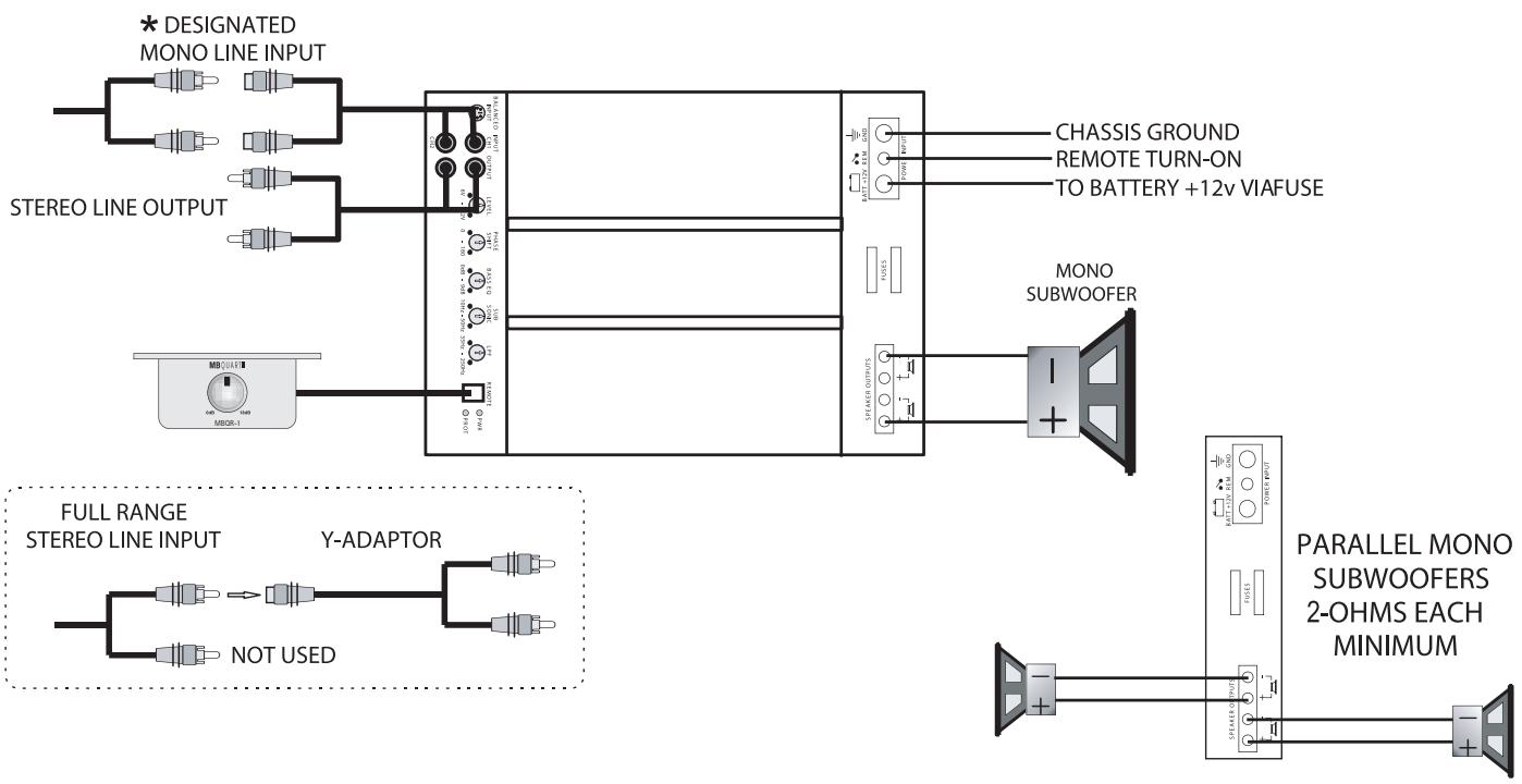
*Note: You can use the Radio/CD designated mono line output or a full range stereo line output.
For full range stereo line output, you will need an optional "Y-Adaptor" as shown
Setting up systems after installation for best performance
General:
As mentioned in the "General Installation Notes" section, the system should now be powered up, and working. At this point, all crossover frequency and input selection switches should be properly set for the application, and all volume, level and equalizer controls turned to minimum.
Level control setup:
Insert a CD or cassette that you are familiar with to use as a reference, and turn the head unit volume control to about 80% of its full setting. The system sound level will of course be very low, and the following procedures will help you to match the amplifier input sensitivities properly to the head unit output signal level.
Single 2 channel amplifier systems:
Turn the level control up slowly, till you hear distortion, then back off a few degrees on the control.
Single 4 channel amplifier systems:
Turn the channel 1&2 level control up slowly, till you hear distortion, then back off a few degrees on the control.
Repeat for channel 3εt4.
2 or 3 way active systems:
Always start with the bass, or low frequency amplifier as a reference, by turning its control up to the point where distortion is audible, and back it off some.
Now adjust the level control for the highs or tweeter channels in a 2 way active system, to balance the highs to lows.
In a 3 way active system, match the midrange level to the bass, and then the highs to the midrange and bass. It may be necessary to perform a few iterations of the midrange and highs level control settings to achieve a satisfactory sound balance.
Crossover frequency fine tuning:
We had started off in the "General Installation Notes" section by setting crossover frequency controls to approximate positions, and now you can adjust these for best sound quality. Be careful not to stray too far from those crossover frequencies as recommended by the loudspeaker manufacturer, as it is quite possible to damage midrange and tweeters with excess power outside their nominal operating frequency ranges.
Equalizer setup:
Once all levels and crossover frequencies have been set for a pleasant sound balance, we can start equalizing the system frequency response. It is important to remember that a boost applied at any frequency, or range of frequencies, will cause severe amplifier clipping. The following comments apply to ALL equalizers and tone controls on the amplifiers, as well as those on head units and dash mount equalizers.
Use the head unit volume control to adjust the system to an intermediate level, and proceed to adjust equalizers and tone controls to personal taste. Now go back to the Level control setup above, and readjust all level controls.
Sit back and enjoy the music!
Troubleshooting a system
The key to finding the problem in a misbehaving sound system is to isolate parts of that system in a logical fashion to track down the fault.
Description of the Diagnostic system built into all MB QUART amplifiers:
The diagnostic system will shut down the amplifier, until reset by turning the head unit off, and back on. This state of affairs will be indicated by the front panel PROTECT LED lighting up under the following conditions:
1 - A short circuit on the loudspeaker leads.
2 - An internal amplifier fault that causes a DC offset on the loudspeaker output.
Should the amplifier go into diagnostic mode, simply disconnect all RCA and speaker leads, while keeping +12 volt, power ground and remote leads connected. Now turn the amplifier back on, and if the diagnostic LED lights, the amplifier has an internal fault.
If not, plug the RCA cables back, and reset the amplifier. If it goes into diagnostic now, the fault lies in the input, either with bad cables or source unit.
If the amplifier seems fine with RCA cables plugged in, connect the speakers, one at a time, and if one of the speakers or its wiring is faulty, it will activate the diagnostic system.
Amplifier heatsink overheating:
The amplifiers will shut down when the heatsink temperature reaches 80 degrees centigrade, and turn back on once the unit has cooled down below that point.
Causes of overheating:
1 - Inadequate cooling - relocate or remount to provide better natural airflow over the fins.
2 - Driving high power levels into low impedances - back off on the volume control, and/or make sure you are not loading the amplifier with less than the recommended loudspeaker impedance.
Low output power:
1 - Check that level controls have been set up properly.
2 - Make sure that the battery voltage, as measured at the amplifier's +12 volt and ground terminals, is 11 volts or more.
3 - Check all +12 volt and ground connections.
Fuses blowing:
1 - The use of loudspeaker impedances below the recommended minimums will draw more current - check.
2 - A short on the main +12 volt cable from the battery to the vehicle chassis will cause the main fuse to blow.
3 - If an amplifier fuse blows continually, with only +12 volt, ground and remote leads connected, the amplifier may be faulty.
System does not turn on:
1 - Check all fuses.
2 - Check all connections.
3 - Measure the +12 volt and remote turn on voltages at the amplifier terminals. If these are non-existent or low, take voltage measurements at fuse holders, distribution blocks, the head unit's +12 volt and remote leads to localize the problem.
Noise problems: System noise can be divided into two categories, hiss, and electrical interference.
Hiss, or white noise:
1 - High levels of white noise usually occurs when amplifier level controls are turned up too high - readjust according to the procedures in section "Setting up systems after installation for best performance"
2 - Another major problem that can cause excessive hiss, is a noisy head unit - unplug the amplifier input RCA cables, and if the hiss level reduces, the source unit is at fault.
Electrical interference:
The inside of an automobile is a very hostile electrical environment. The multitude of electrical systems, such as the ignition system, alternator, fuel pumps, air conditioners, to mention just a few, create radiated electrical fields, as well as noise on the +12 volt supply and ground. Remember to isolate the problem - first unplug amplifier input RCA cables, if the noise is still present, check the speaker leads, if not, plug the RCA's back, and investigate the source driving the amplifier, one component at a time.
A ticking or whine that changes with engine RPM:
1 - This problem could be caused by radiation pickup of RCA cables too near to a fuel pump or a distributor, for instance, - relocate cables.
2 - Check that the head unit ground is connected straight to the vehicle chassis, and does not use factory wiring for ground.
3 - Try to supply the head unit with a clean +12 volt supply directly from the battery ^+ , instead of using a supply from the in dash wiring/fusebox.
A constant whine:
This type of noise can be more difficult to pinpoint, but is usually caused by some kind of instability, causing oscillations in the system.
1 - Check all connections, especially for good grounds.
2 - Make sure that no speaker leads are shorting to exposed metal on the vehicle chassis.
3 - RCA cables are notorious for their problematic nature, so check that these are good, in particular the shield connections.
Inhaltsverzeichnis
- 1/2 CH X-OVER: Position "HI"
- 3/4 CH X-OVER: Position "HI"
Mode mono large bande
- HI PASS: 100 Hz
- LOW PASS: non applicable
- HI PASS: non applicable
- HI PASS: non applicable
- LOW PASS: non applicable
- LOW PASS: non applicable
- HI PASS: non applicable
- HI PASS: non applicable
- LOW PASS: non applicable
- LOW PASS: non applicable
Canaux 1/2:
- HI PASS: 100 Hz
- LOW PASS: non applicable
Canaux 3/4:
- HI PASS: 100 Hz
- LOW PASS: non applicable
- CH 1/2 HIGH PASS: non applicable
- CH 3/4 HIGH PASS: non applicable
- CH 3/4 LOW PASS: non applicable
- CH 5 LOW PASS: 100Hz
- Mode INPUT: Position "CH2"
- CH 1/2 X-OVER: Position "HP"
- CH 3/4 X-OVER: Position "BP"
A工程技术 of the selection of diplexor (X-Over) can be used to select a function of the inner product.
A工程技术 of the 1/2CH X-OVER) is possible to implement a signal in a device that can be used for the purpose of the proposed technology.
A工程技术 of the 3/4CH X-OVER) is used to design a device that can be used in the field of communication.
BxObl Line Ha Cinch-rHe3ax IJnI nap KaHajOB 1&2, 3&4, a TaKxe KaHajIA MONO
- 3TN BxOdb MoRy T NcNtB30BaTbC B Pa3NtHbX CoTeaTHnX Iyn OnpEeJeHHo RpIMHeHn IN B 3aBncMocTn OT HAcTpoek NepeKInOHaTeJI BxOHDoro peJIMa (MODE) IN PepeKInOHaTeJI YacToTbX pa3dIInTeJbHbIX PhINbTPOB (X-OVER) Iyn KaHajOB 1&2 nIN 3&4.
MoHO-ycnHtEnb: paccHTan Ha 4,2&1 OM.
- PHASE-Shift (corlaocabHme noIoxeHnna 4a3b) nO3B0JraT BbIOJIHrTa onepaunn HactpoKn B danaasohe 0^ - 180^
- LEVEL: B pe3yIbTaTe 3TOr BOxHNoI yPOBHeY BCYNInTeJg (Gain) MoKeT 6bITb corIacoban C bIxOxDbIM yPOBHeMa paINOpNIeMHnka/CD-Tnpeepa.
- POWER:ПосpeдтбомЗагорпязеленогсбетоюногиИнdkаTopa nokak3bIbaeTc,чToHa yCINITeIb NOCTynaet TOK,IMeETc coeDnHne C 3emNe,a ynpabLeHne BkIIuOchEmЯBJIeTcA kTbHbM (REM).
- PROTECT: 3aropanheиндikatopa PROTECT o3haeayet,чToB yCunnteIe IMeTcA HeCNpabHocTB,иTOO h He roTOB K paBoTe.CyueCTByHT HeckoKb BINOb Ipo6nem KOTOpbe npINBOJrT K peKeKIIuOHeHIO ycNITeR B 3auNThB pExM.ДЯ nIoUyeHn6 BoJe nOIpOboHoi INHOpMaUcIM CMOtrn HInCTpyKUHIO NO NOnCKy HeCNpabHocTe, KOTopra NOMeUeHa B NocLeHNe Yactn pyKOBOdCTBa NO 3KcNlpyatauN.
-BALANCED INPUT: npHnMaet CmmMeTpUHbIe BxoHbIe yoBn B daHa3OHe 0,4B-18B.
TOnHoDnana3oHHbI cTepeo-peXIM
3To Han60lee yacto BCTpeuaoumci sCnya oCHOBHOrO npImHeHn2-kaHaJIbHbIX ycIInTei cepnn Premium.
- KoHTpOlbHbI IpeueHbI pyo coeINHeHn pnoBOdoB:
Cinch-BxoDbI (LINE IN) nocpeDCTBOM BbICOKKaueCTBeHHbIX Cinch-Ka6eNei coeINHt b paadinopnemHKom/CD-nnepom.
- IpekeKIOUOATEb YacToTHOro pa3dJIteHbHorO fIbIbTa (X-OVER):
IpekeIIOuateIb YactoTHOro pa3JeINTeIbHOro fJIbTpa DOnJKeH HaxOINTBcB B noLoXeHN "FULL".
- KontpolnbHnpeueHbI pyerynipobaHn yactToI nepexOda:
He OTHOCITc K IIOHODIana3OHOMy peKIMy (FULL).
4.BxOJaHyUByCTBHTeJIbHoCTb (LEVEL):
CMOTn pa3dJI "HAcTpoiKa CnCTeMbI NocLe MOHTaKa IJRA DOCTNKeHnRA HAnNyUHSe MoUHOCTI"
- Mdunb dntaHnOHHO ynpabHeHH Hm3KIMN qactotaM:
Moynb nctanuohnoHoro ynpaBnEHH N3KMMN cactotamn nocpecdtBOM mHeOeOcR B KOMnIKeTe ynpaBnHOUe KObEni noKnIOuHTb Ha rHe3e "REMOTE" ycInnteJ.
DIPMeyAHME:
MHNMYM DIIY COBOKUynHbIX IMNpeDaHCOB DnHaMnKOB
4&2OMBCTepeo-peximeIIM4OMBMOHO-pexime.
3T0T yCINIeHbHe pa6oTaet B cTepeo-pexKIMe 1 OM mIIMoHO-pexKIMe 2/1 OM.
KaHaJIbI 1/2: KaHaJIbI 3/4:
- HI PASS: He noJxOДNT - HI PASS: He noJxOДNT
- LOW PASS: He noxOuT - LOW PASS: He noxOuT
KohtpohblnpeuehenbIaHnaHctpoKnpeyIaTOpOByPoBHa:CMToPnpa3deI
"HaCtpoJa CInCTe MOnCTe MOntaKa IJINI POJIyUeHnHaHJIyUeJeM OMOuHocTn."
MHHMymIJIaCOBOKyTHbIX MmTeJaHcOB DnHAMKOB:2OMHaKaHaJ
-Подклioчпь полжnteльный писоeДинтelын 3аЖМ МОНО-DинамИКаВ COOTВETCTBm C pncyHKOM K pa3bemy "LEFT +", a орtuцateЛьньз 3aЖМ K pa3bemy "RIGHT -".
KohtpOBhBnI nepeYeHb Iy HacTpoIKn peekJIouaTeJe pa3deJInteMbHbIX ΦHbTpOB:
-1/2CHX-OVER:poJoxeHne“FULL
-3/4 CH X-OVER: noJoxeHne "FULL"
KohtpohblnpepehenbIaHnactpoKnpeylanTopobnepexodaacTobl:
KaHaJIbI 1/2: KaHaJIbI 3/4:
- HI PASS: He noJxOДNT - HI PASS: He noJxOДNT
- LOW PASS: He noxoxuNT - LOW PASS: He noxoxuNT
CobET: EcnBbIcNoIb3yeTe BixOHa cAb6Byeep akTbHOro pa3dEnIteIbHoro fNtbpTa, pni 3TxN yCNInTeJx BNOJIHe MOxHO NpKIOuHHTb FInbTp HIXHX XaCTOT, TOb6blpoUyHb 60oe 3NaHTeJIbHyO KpyTH3Hy aCTOTnX xaPakTePncTnK FInbTpA HIXHNX YactOT.
KohtpohblnpeuehenbIaHnaCTpOKnpeyIaTOpOByPoBn:CMToPnpa3dJe
"HaTpoKa CnCTeM Iocse MOtTaKa IpnIyUeHnHaNlNyUeHmOuHOCTeM
MHHIMYM DnIy COBOKYINHbIX NIMPeJaHCOB INHaMHKOB:
-2OMHaKaHaJI BCTepeo-pexIMe.
-4OMBUHTyHTPOBaHHOMMOHO-peJxHMe.
2-KaHaJIbHaj aKTUBHaj IIN DByXcHInTeJbHaj CmCTema C Hn3KIMN YactOTAm "MOHO"
3Ta KOMNHOBka NOKa3bIbAeT, KAK MOKHO pOcTBm IyTeM C INCNOB3OBAHnEM 4-KaHaJIbHO rCINITeMa moEJIbHO rpaD Apremiu yCTaHOBnTb 2-KaHaJIbHyIO AKTNBHyOCNTeMy. KaHaJIb 1 n 2 INCIOJIb3yIOTc dIra BbICOKNX aCTOT, KaHaJIb 3 n 4 nIy Hn3KnX YactOT "MOHO".
KohtpoNbHbI piepeueHb IJIa coeINHeHn npoBODOB:
MbIdoJNkhblnoaTbOJnHakobblcHnHaNbO6aBxOa(LINEIN),no3ToMycneJeYet nCIOJIb3ObaTbDyA-danTepe,odHN aanTepdI toro,yTO6bIBcoOTBeCTBmC pncyHKOM noaTbLeBblcHnBkKaHaNbl1n3,aTaKxE BTOpO aanTep,yTO6bl noaTb npabblcHnBkKaHaNbl2n4.
TIOKJIUOHeHMe MoHO-ca6ByΦepa:
CoedHHntb pnoJXHTeHbH pnIcoeHNHTeHbH 3aJIM MOHO-DINHAMKc 3aJIMMO "LEFT ^+ , "OtpuataTeHbH 3azJM c pa3beMOM "RIGHT .
KohtpOlbHbI nepeueHb IJRA hAcTpoIKn peekJIIOuATEJeI pa3deJIInTeMbHbIX ΦINbTpOB:
-1/2CHX-OVER:noJIOxHeHne,Hi
-3/4 CH X-OVER:юJOxHeMe,LP/BP
KohtpohblnIpeuehenbIaHnaCTpOKnpeyIaTOpBuaCTToIpeexoHa:
Kahalb1 1/2: KaHaJIbI 3/4:
- HI PASS: 100 Γι - HI PASS (ДοЗвковов): 20 Γι
- LOW PASS: He noidxoit - LOW PASS: 100
POMHNTe O TOM, YTO 3TN pA3dJIteJIbIbIhe YAcTObIbI YBJIbHTc JINIbIpEINOJKeHMAI. POpOBepITb CNEUΦNkAuzn N3rTOBtIeJIa DnIaHAmKOB IN IpoHITaTb pa3dJI " HAcTPOka CnCTEm TocNe MOHTaKa dIg POJyEHn HAInyUsh MOnHOCtN."
KohtpoNbIy IpeueHbI pyeYJrTOpOB LEVEL: CmToPi pa3dEi "HaCtpoKa CnCTem nOcIe MOtaxa IyIPOJyEHNHaHJyUeM OuHocTn".
MIMHMYMДЯ COBOKYINbIX IMNEJaHCOB DnHaMnKOB:
-2OMHaKaHaN BCTpeo-peKIMe.
-4OMBMOCTOBOI CXEMe“MOHO”.
2-KaHaJIbHЯ aKTbHЯ nIIN DByXcNJInTeJIbHЯ CnCTeMa C HIXHMn YacTOTAMN “MOHO” M NIKUpOBaHHeM BbICOKHX/HN3KHX YacTOT
B daHHom cnyaeMbI pIeCTabJIeM OIN I3 BapnAHTOB H3BaBHOn BbIe CNTEmbl. TaK KAc B daHOM cnyae peHy nIeT O 2-KaHaNbHOJ CNTMe, Ml MoXeM NcNoJIb3OBAbT fpoHTaJIbHbIe BbIXOdbI yCTPOJCTBa YnpaBNeHnY, TTO6bl AKTNIBPOBaT bNcOKHe cactToBI, I 3aDHNe BbIXOdbI, YTO6bl AKTNIBPOBaT hN3Kne YactToBI. Bpe3yJIbTaTe BbIOJIHHeN NIOo6bHx DeIcTBNI C NMOU bOp eYrJIaTOpA dIg peYrIipOBaHnY UPOBn CnHApA cpePdN i C3aDN (fader) Ha yCTPOJCTBe YnpaBNeHn CnuWateNB MoXeT Be3 Tpyda aJaTIPoBAbT OTHOCInTELbHI yPoBEhN HN3Knx YactOT K BbcOKIM YactOTAM. KaHaJIb I n 2 NcNoJIb3yIOTcI DnB BbcOKNX cactOT, KaHaJIb 3 n 4 dIy HN3Knx YactOT "MOHO".
Kohtpobhbl nepeueHb IJIa coeHNHeHn npoBOIOB:
IcnoJb3oBaTbBicOkaaHeCtBeHbIe CInch-ka6eIINIpaNIOKluOeHnBxOIOB yCNIITeJIeK IcToHknyCoIaNo pucHyKy.
BbINOHNHTe DeCTBnO tHOCHTBnHO HAcTPOKn NepeKJIHOaTeJe YacTOThBIX pa3dIeNTbHbIX dNtBPOB N HAcTPOKn NepeXoOB YaCTOT TaK, KaK 3To bblno yka3aHO dIra CNTEmbl, KOTOPa ONiCAHa Bblue.
ФильТр ВьICOKИX YacTOTВперднEи 3аднeчСи NCПОЛБЗOBAHnEM 2-КаHAJIbHOrO yCINlnteЯ ДЯМоно-ca6Byфepa
BpeyIbTaTe KOM6HnHPOBaHnra 2-KaHaJIbHOro yCNIHTe n C 4-KaHaJIbHbIM yCNIHTeMe CNCIOJIb3OBAHNEM INTErPnPpOBaHHbIX pa3DeJIInTeNbHbIX pINbTpoB MOxHO CKOMIOHOBaTb JERKYU, KOMIIeKTHyIO CnCTEmy C BbICOKMm YactOTAMN BpeEHei 3aJHei Yactn I MoHO-caBByfepom.
KohtpoJIbHbI nepeueHb IJn coeINHeHn IPOBODOB:
-ИсnotьуBaIcOKokaueCTBeHHbIe Cinch-ka6JIi,CoeHNHtBpeEHNHe 3aDnHe BbIXOblyycTpoIcTBaUnpaBLeHnCOrIaChoPncyHkycoBXOaMn(LINE IN)4-KaHaJIbHorO yCINITeJI.
-ToHToTakJxHe3IO LINE OUT 4-KaHaJIbHOrO yCINITeIg CoIlaCHO pncyHky coeIMnItb C rHe3dOM LINE INPUT 2-KaHaJIbHOrO yCINITeIg.
ПодклоченHeMoHO-ca6Byфepa:
KaHaJIbI 1/2: KaHaJIbI 3/4:
- HI PASS: 100 Φ - HI PASS: 100 Φ
- LOW PASS: He noIxOuNT - LOW PASS: He noIxOuNT
2-KaHaJIbHbIyUcNJITeJIb HN3KINx qAcTOT:
-HI PASS(ДоЗвковофильт):10 Г -40 Г
- LOW PASS: 100 Γu
POMHNTe O TOM,чTo 3TN pAsTeJIteIbIbIe HaCToTbIЯBJIAOTcIaIIbIpeJIOXeHIMM. IPOBepuTb CteUΦKauZn N3rTOBtIeIaI DnAINHaMkoB IpoHuTb pa3Je "HactpoKa cIcTeM nOcIe MOtJa dI NaJIoYeuHn HaNlyUyIe MoUHocTn."
KohtpoNbI nepeueHd IaI peyJrTopOB LEVEL: CmToPi pa3dJI "HaCtpoNk CnCTeM nOcIe MOThaKa dIJI POJIyHuHnHaHJNyUe MOnuHOCTN".
MHHIMYM DnIy COBOKYINHbIX NIMPeJaHCOB INHaMHKOB:
-2OMHaKaHaN BCTepeo-peKIMe.
-4OMBMOCTOBOXCEME“MOHO”.
KoHΦnIgypaizna B BVide 5 DnCKpeTHbIX KaHaJIOB, OdINH KaHaJI B KaYeCTBe MOHO-ΦnJIbTpA HnXHnX YaCTOT
BbMOKeTe NcNoJIb3OaBb 3Ty KOHcIgYpauCIO npocTo KaK cIcTeMy C 4 IINCKpeTHbIMN
POnIOHOJnAa30HHbIMN KAnaAMN INTbIM KAHaJOM HNI3KHX YAcTOT. Bce pa3dJIeNTbHbIE
ΦIbTpbl baiNaCmPoBaHb, 3a NcJIuOHeHMe ΦIbTpPa HIXKHX YAcTOT Ha KaHaJ 5.
PiTa bKaHaJOB MOrYT NcNoJIb3OaBbCra TaKke C BHEUHM aKTNBbIM pa3dJIeNTbHbIM
ΦIbTpom JIn6o C pa3dJIeNTbHbIMN ΦIbTpAm B yctpoiCTbAx ynpaBNeHn IIN
3KBaJau3epax.
KohtpoJIbHbI nepeueHb IJn coeINHeHn npoBODOB:
Плдклочь BXOы (LINE IN)Дla KaHа 1&2 Ha nepeDнн BbIXOD, KaHajI b3&4 Ha 3aДнн BbXOD, a TAKKe KaHaN 5 Ha BbIXOD MOHO-cabBycpepa yctpoiCTBa ynpabJIeHnЯ nHa 3KbAanJepe B npB6OpHOn paHJI.ФИьТР LOW PASS Ha kaHaN 5 BkIIOuAeTcNocIeDoBaTeBJHoCФИьТPOM NCTOChNka. BblMOKTe JIo6 HAcTPOITb erO ha TakyO He JaCTOTy, YTOb6 IOnlyuHTb BoJIeE 3HaHHTbHyO KpyTIN3Hy JaCTOTHOnxapakTeRpICTNKIn, JIo6 Ho 6BoJIe BeBICOKYU JaCTOTy, YTOb6 "CMrHNTb" erO BIIraHne. IToTоJxe PnIuHHe DnI PoIyUeHnE 6OJIeE 3HaHHTbHON KpyTIN3Hb IOnkIIOchTb NepExoDbIФИьТр BaBICOKX JaCTOT dJa KaHana 1, 2, 3&4.
KohtpohblnpeueHbIpyHacTpoKnpeeknOuateJeYacToTHbIX pa3deNtBhlXΦnIbTPOB:
- INPUT-Modus: noJooHeNe,5CH DISCRETE"
- CH 1/2 X-OVER: noJIoXeHne "FULL"
- CH 3/4 X-OVER: noJIoXeHne "FULL"
Kohtpohbln pepeueh bI naHcTPOk npeyIaTOb VacToBtI nepeXOda:
-CH1/2HIGHPASS:He noxdxoDnT
-CH3/4HIGHPASS:He noDxoDHT
-CH3/4LOWPASS:HepoIxoIuT
-CH5LOWPASS:100T
ПOMHNTe O TOM,чTO 3TN pA3dJIteNtBbIbe YAcTObTbIЯBJYOTcR IINbIpeJIOXeHnMIM. O3hakombTebc CO cneLmФИKACUZMIM N3rTOBHTeIДгДиHAMKOBИ pA3dJIOM "HacTpoKa CNTem Nocle MOHTaKa Дг ПОЛУЧЕнHAHIyUWeMoUHOCtN".
KohtpoNbIy IpeueHbI pyeYJrTOpOB LEVEL: CmToPi pa3dEi "HaCtpoKa CnCTem nOcIe MOtaxa IyIPOJyEHNHaHJyUeM OuHocTn".
MHHMymДЯ COBOKYIHbIX IMTeJaHCOB ДИHAMIKOB: 2ОмHa KaHani
KoHΦnIgypaizna B BVde 3 nII 4 nckpeTHbIX KaHaIOB, OINH KaHaJI B KaYeCTBe MOHO-ΦnIbTpHa HIXHX YaCTOT
B daHnom clyae mbI nIcIb3yem Ty Je 6a3oByIO hactpoKy, KaK yka3aHO Bblie, YTO6bI pIepdctABnTb 3-KaHaJIbHyO CNTeMy, PnI 3OTM mbI BKIIOnyae MnpBI KAnAOB "CTepeO" 1&2 I 3&4 B MoCTOBYIO CXEMY "MOHO".ДЯ 4-KaHaJIbHOI CNTeMbI MOHTAK B BVJe MOHO-MoCTA ToIbKO pI np IcNcIb3OBAHN KAcoi-JInbo napBI kaHaJIOB.
KohtpoNbHbI piepeueHb IJIa coeINHeHn npoBODOB:
- IcnoIb3oBaTb 2 Cinch-ka6eJy-AaanTepe, oDIN dIy KaHAnOB 1&2, a BToPOn dIy KaHAnOB 3&4, yTO6bl corgnacho pncuHyco3daTb TOnko 2 BxOJa dIy KaHAnOB 1, 2, 3&4.
Hn3kayBbIXoHnaMoUHocTb:
1-Поверпь,настофылп peуглары урвая наділіжачи мобразом.
2-06ecneHTbTo,TOb6bI B0BpMaBbIPOJIHeHn3aMepa HapPjaKeHne 6aTapeHn TaTePMHaJax+12B IN TepMHaJax MaccbIcoCTabJINo He MeHee 11 B.
3 -Пювоверпь С党支部 Клиоченя +12 В и полк nullец на масу.
IpeperopaoT npedoxpanHnTeHn:
1-NCIOJIb3OBAHHe IMNEJaHCOB DnHAMMKOB HIXe peKOMeHNoBaHHbIX MHNIMaJIbHbIX 3NaueHNI NOTpe6BJIeT 60JIbe TOKA -IPOBepNTb.
2-KopotKoe 3ambikaHne Ha MarInctpaJIbHom Ka6ene +12 B ot 6aTapeN K Iaaccn ABTOMO6IJI pINBOJNT K TOMY, UTO pepeRopaET rAbaHbI pPeOxPAHITeJIb.
3 - Ecn noctoHno neperopaet npedoxpaHntelb ycInTeI y nOdknOHeBToJIbKo Ka6eI +12 B, Maccbl uynpaBneHna BKIOueHem (REM), Bo3moKHO, HeNCpabEn ycInTeIb.
CnCTema He BKJIOUoaeTcR:
1-Поверпь ВспедханITEЛ.
2 -Поверпь BCE KJIEMMbl.
3- Ha TepmHaJIbHbIy ycTpoCTbax HapJxKeHnIz 3aMePntb HapJxKeHne +12 B n HapJxKeHne BkIIOUeHnIgCTaHcIIOHOrO ynpaBLeHnIg. EcII n HapJxKeHne 6byet OTCYCTBOBaT, IIn60 OHO 6ByET HN3KIM, BblONIHb T3aMePbI hapJxKeHnIg HApJxKeHnIg AepXaTeJIg PpeIOxpaHtJIeI, pacppeJeTIeJIbHbIX 6loKax, Ka6JIax +12 B n Ka6JIax NCTaHcIIOHOrO ynpaBHeHnO cOChOBHO rycPoCTBa, YTO6bl IokaJIIN3rpoBaT np6bnemy.
Ipo6nmbi, Cb3aHbIe C yMOM: CNTeMHbIe 1yMbI MoKHO pa3JeNt b Ha IBe KaTeOpIM: UINHeHne HJNEKTpUHeCKHe INTEppepeHUN.
LIIHHe HnIb6bnIe lyMbI:
1-cnIbHbI6bIyM0bIHyNIOBnIeTcTOrJa,KoIapeYJrAToPbyUPOBHN yCINITeJIe(yOBeHb)HAcTPOeHbHa CNIuKOM 6bIyU BoJIuHInHy.Eue pa3 BblONIHt b HAcTPOkyB COOTBeTcTBm CnpjKOM DeIcTBm,I3IOKeHbIM Ba3JeIe“HAcTPOka CNCTMbIOCEMOHTaKaDJIPOUYeHnHAHIyUeero 9cpeKTe 3ByaHnI".
2-Дугая причпьа, которая может привеси К появлению чyperмерно сильношименя, СкрыbaeТСВ сильшем EMCTOЧИКЕ ПИТАНЯ -OTCOЕДИNTb cinch-kaбели BXODа усINITEЛ.Если тЕпьуровь SHMa yMeHBshITcR, 3HAHIT, HENICPABHOCtB hAXODITСВ B INCTOCHNKe ПИТАнЯ.
3NeKtpnueckne INHTeppehenHIM:
O6bpyoBaHnE, haxoJaIeecB HByTn ABOTMO6nJI, npdctabJIeT co6oi, kak npaBnIO, He6laonpnaTHyU cpeD yIra fynHKuONHPOBaHnA 3neKTPnueCKHX yCTpoiCTB. BoJbShoe YcNLO 3NeKTPnueCKHX CnCTEm, HanPIMep, 3aXgRHaNE, rHepeTOp, 6EH3OHaCoCbI, KOHNIOHep, 3TO LIIbHECKoJIbKO I3 MHOINx UCTpoiCTB, Co3aHOT 3NeKTPOMaHHTNble NOIa, a TAKKe 7MbI B 30He NpOKJIuChENr KaBeJIe +12 B n 3a3eMlneHn. KAc Bcerda, B DaHHOM Cnyae Toke HJXHO ONPeDEJIb MeCToHAXOJDeHn ENoIaIKN - Bhauane OTcoEINHtB cinch-KabeBI BxOJa ycINITeJI. EcnI NoCte 3TO rWoMbI He NcYe3HTY, PNOBepITb KaBeNI DnHAMNKOB. EcnI HET, ChOBA NpOKeINHtB cinch-KabeNI ycINITeJI IN pOBepITb MCTOHNK, OT KOTOPOro 3aIITAH ycINITeJI, BcER da ODNH KOMNoHENT NocJe dpyrTO KOMNoHENTa.
TUKAHbe HIN CBNCT, KOTOPbIE MEHJOITcB 3aBNCMOCTN OT YACTOTbl BpaJeHnA DBIRATEJI:
1-3ty npo6IeMy moJHO o6bAChnTb IpoHNIKHOBeHHeNem 3JIeKTpMaHHTbIX nOJIeB CInch-Ka6eIy ycINInTeJIa, KOtOpBie, HApNIMep, IpoXoJaT cJInsKOM 6JIn3KO O T 6eH3oHacoc a JIn PaCppeJeTIeJI. IpoNoXt b Ka6eJI no-DpyrOmy.
2-Поверпь, coeДиЕна ЛКлЕмma "Земma" OСОВHOrO yCTpoIcTBA HeNOCpeIcTBeHNo CшAccn abTomobилЯ, И He 3a3eMJIeHa JIn OHa Yepe3 6OpTObYIO cTeB.
3 - Плобайтесь сешинны осовhoe устовпосрдевим кабел +12В
Наразмус с пожителовим пож�имбатар,在BMETOТО,чтобп пожкючыт
EROССПОБСТАнДAPТНОКабелов развдк/блoka п dedохалгень в спнту
приборов.
TIOCTOHHbCBNCT:
ПиИИУ 3TOВО BIVaIbIshy MoBbIX NOMEX, B 3aBcIMOCTN O T O6CTOЯTIELCTBa, ONPeJELNTb CIOKHeE, OJHAKO ObIyHNO OHa CO3JaTeC KAKOJI-Ni6o ФОмо HeCTa6JIbHOCtIN CnCTeMbl, KOTOPaI PrIVbOHT K NOBbIeHINO HApUShenB I Ba6ote CnCTeMbl.
1 - Поверпь В СЕ ПОДКЛЮЧЕНИA, В OCÖБЕНСТИ, OTHOCITeNBHO HAneJXHORO 3a3eMJIeHIN.
2-Y6eHITbcB TOM, YTO Ka6eJIIN HINHAMKOB, IPOXOJIAUne IIO OTKpbIToM METaJIInuecko IOBEPXHOCTN HE CO3DAOT KOPOTKO 3AMbIKAHNA C UACCN ABTOMO6NJ.
2-Cinch-Ka6eIN N3BcTbI CBOeI paCIOJIOKeHHocTbIO K BO3HMKHOBeHIno Ipo6IeM, IO3TOmy IpOBepNTb IV COCTOAHHe, B CaTHOCtN, 3KpaHnIPyUOJIne CoEiINHeHn.
| Features | PAB 2100 2-CHANNEL | PAB 4100 4-CHANNEL | PAB 5400 5-CHANNEL | PAB 1200.1D MONO |
| Output Power Rating Watt RMS (14.4V battery) | ||||
| 4-Ohms | 100 x 2 | 100 x 4 | 55 x 4 + 200 x 1 | 600 x 1 |
| 2-Ohms | 200 x 2 | 150 x 4 | 80 x 4 + 300 x 1 | 800 x 1 |
| 1-Ohm | No | No | No | 1200 x 1 |
| Mono Bridged at 4-Ohms | 400 x 1 | 300 x 1 | 160 x 2 + 200 x 1 | No |
| Mono Bridged at 2-Ohms | No | No | No | No |
| Power Supply | PWM | PWM | PWM | PWM |
| Output Power Circuit Configuration | Mosfet | Mosfet | Mosfet | Mosfet |
| Miscellaneous Spec | ||||
| Soft Start Sound | Yes | Yes | Yes | Yes |
| Input Selector S/W | No | - | No | No |
| Frequency response -3dB | 10Hz - 30KHz | 10Hz - 30KHz | 30Hz - 30KHz | 10Hz - 250Hz |
| Damping Factor | - | - | >185 | >260 |
| S/N Ratio (A-Weight) | 95dB | 95dB | >93dB | 95dB |
| THD | 0.05% | 0.05% | 0.03% | 0.10% |
| Channel Separation | 70dB | 70dB | >72dB | - |
| Variable Input Level Control | 0.2V-6.0V | 0.2V-6.0V | 0.2V - 6.0V | 0.2V-6.0V |
| Input Impedance | 47kΩ | 47kΩ | 47kΩ | 47kΩ |
| Diagnostic Indicator | Power/Protect | Power/Protect | Power/Protect | Power/Protect |
| Protection (DC, Short, Thermal, Overload) | Yes | Yes | Yes | Yes |
| Crossover Operation | ||||
| Crossover S/W for 1+2 channel | LP/FULL/HP | BP/FULL/HP | BP/Full/HP | - |
| Variable Hi-Pass/Subsonic Filter | 10Hz ~ 150kHz | 10Hz ~ 150kHz | 50Hz ~ 4kHz | - |
| Variable Low-Pass (Mono 24dB) | 30Hz ~ 150 Hz | 30Hz ~ 150 Hz | 35Hz ~ 250Hz | 35Hz - 250Hz |
| Variable Subsonic Filter | Included in Hi-Pass | Included in Hi-Pass | Included in Hi-Pass | 10Hz - 50Hz |
| Bass Boost at 45Hz | 0 ~ 9dB | 0 ~ 9dB | 0 ~ 9dB | 0 ~ 9 dB |
| Crossover S/W for 3+4 channel | No | BP/FULL/HP | No | - |
| Variable Hi-Pass | No | 10Hz ~ 150Hz | 50Hz ~ 150Hz | - |
| Variable Low-Pass (Mono 24dB) | No | 30Hz ~ 150 Hz | 250Hz ~ 4kHz | - |
| Variable Subsonic Filter | No | Included in Hi-Pass | Included in Hi-Pass | - |
| Bass Boost at 45Hz | 0 ~ 9dB | 0 ~ 9dB | 0 ~ 9db | - |
| Crossover S/W for channel 5 | No | No | No | - |
| Variable Low-Pass | No | No | 30Hz ~ 150 Hz | - |
| Bass Boost at 45Hz | No | No | 0 ~ 9db | - |
| Line Output | Full Range | Full Range | Full Range | Full Range |
| Unbalanced Input (RCA Jack) | Yes | Yes | Yes | Yes |
| Balanced Line Input (DIN) | No | No | No | Yes |
| Phone Jack for Remote Control | Yes | Yes (3+4CH) | Yes (CH-5) | Yes |
| Bass Boost Remote Control Module MBQR-1 | Yes | Yes | Yes | Yes |
| Others | ||||
| Power Terminal (gold-plated) | 4-GA | 4-GA | 4-GA | 2-GA |
| Speaker Terminal (gold-plated) | 12-GA | 12-GA | 12-GA | 10-GA |
| Fuse Size | 50 Amp | 2 x 50 Amp | 2 x 50 Amp | 2 x 40 Amp |
| Dimensions in inches (L/H/W) | 13.4 x 2.25 x 10.4 | 18 x 2.25 x 10.4 | 19 x 2.25 x 10.4 | 17 x 2.25 x 10.4 |
| Features | PAB 2100 2-Kanal | PAB 4100 4-Kanal | PAB 5400 5-Kanal | PAB 1200.1D MONO |
| Ausgangsleistung Watt RMS bei 14,4V | ||||
| 4-Ohm | 100 x 2 | 100 x 4 | 55 x 4 + 200 x 1 | 600 x 1 |
| 2-Ohm | 200 x 2 | 150 x 4 | 80 x 4 + 300 x 1 | 800 x 1 |
| 1-Ohm | Nein | Nein | Nein | 1200 x 1 |
| Mono gebrückt an 4 Ohm | 400 x 1 | 300 x 2 | 160 x 2 + 200 x 1 | Nein |
| Mono gebrückt an 2 Ohm | Nein | Nein | Nein | Nein |
| Netzteil | PWM | PWM | PWM | PWM |
| Konfiguration Ausgangsspannungsteil | Mosfet | Mosfet | Mosfet | Mosfet |
| Diverse Spezifikationen | ||||
| Soft Start | Ja | Ja | Ja | Ja |
| Eingangswahlschalter | Nein | - | Nein | Nein |
| Frequenzwiedergabebereich -3dB | 10Hz - 30KHz | 10Hz - 30kHz | 30Hz - 30KHz | 10Hz - 250Hz |
| Dämpfungsfaktor | - | - | >185 | >260 |
| Signal-Rauschabstand | 95dB | 95dB | >93dB | 95dB |
| Klirrfaktor | 0.05% | 0.05% | 0.03% | 0.10% |
| Kanaltrennung | 70dB | 70dB | >72dB | - |
| Schaltbare Eingangsempfindlichkeit | 0.2V-6.0V | 0.2V-6.0V | 0.2V - 6.0V | 0.2V-6.0V |
| Eingangsimpedanz | 47kΩ | 47kΩ | 47kΩ | 47kΩ |
| Power und Diagnose LED | Power/Schutz | Power/Schutz | Power/Schutz | Power/Schutz |
| Schutz (DC, Kurzschluss, Überhitzung, Überlast) | Ja | Ja | Ja | Ja |
| Frequenzweichen Betrieb | ||||
| Frequenzweichenschaltung Kanal 1+2 | Tiefpass/Vollbereich/Hochpass | Bandpass/Vollbereich/Hochpass | Bandpass/Vollbereich/Hochpass | - |
| Variablen Hochpass-/ Subsonic Filter | 10Hz ~ 150kHz | 10Hz ~ 150kHz | 50Hz ~ 4kHz | - |
| Variablen Tieffpass (Mono 24dB) | 30Hz ~ 150 Hz | 30Hz ~ 150 Hz | 35Hz ~ 250Hz | 35Hz - 250Hz |
| Variablen Subsonic Filter | Enthalten im Hochpass | Enthalten im Hochpass | Enthalten im Hochpass | 10Hz - 50Hz |
| Bass Boost bei 45Hz | 0 ~ 9dB | 0 ~ 9dB | 0 ~ 9dB | 0 ~ 9dB |
| Frequenzweichenschaltung Kanal 3+4 | Nein | Bandpass/Vollbereich/Hochpass | Nein | - |
| Variablen Hochpass | Nein | 10Hz ~ 150Hz | 50Hz ~ 150Hz | - |
| Variablen Tieffpass (Mono 24dB) | Nein | 30Hz ~ 150 Hz | 250Hz ~ 4kHz | - |
| Variablen Subsonic Filter | Nein | Enthalten im Hochpass | Enthalten im Hochpass | - |
| Bass Boost bei 45Hz | 0 ~ 9dB | 0 ~ 9dB | 0 ~ 9db | - |
| Frequenzweichenschaltung Kanal 5 | Nein | Nein | Nein | - |
| Variablen Tieffpass | Nein | Nein | 30Hz ~ 150 Hz | - |
| Bass Boost bei 45Hz | Nein | Nein | 0 ~ 9db | - |
| Line Ausgang | Vollbereich | Vollbereich | Vollbereich | Vollbereich |
| Unsymetrischer Eingang (Cinch) | Ja | Ja | Ja | Ja |
| Symetrischer Eingang (DIN) | Nein | Nein | Nein | Ja |
| RJ-Buchse für Fernbedienung | Ja | Ja (Kanal 3+4) | Ja (Kanal 5) | Ja |
| Bass Boost Fernbedienungsmodul MBQR-1 | Ja | Ja | Ja | Ja |
| Weitere | ||||
| Batterie/Masse-Anschlussterminals (vergeldet) | 25 mm² | 25 mm² | 25 mm² | 35 mm² |
| Laufsprecher-Anschlussterminals (vergeldet) | 4 mm² | 4 mm² | 4 mm² | 6 mm² |
| Gerätesicherung | 50 Amp | 2 x 50 Amp | 2 x 50 Amp | 2 x 40 Amp |
| Abmessungen in cm (L/H/B) | 34 x 5,7 x 26,3 | 45,8 x 5,7 x 26,3 | 48,6 x 5,7 x 26,3 | 43 x 5,7 x 26,3 |
74847 Obrigheim, Germany
Phone +49 (0) 62 61 - 6 38-0
FAXX +49 (0) 62 61 - 638-129
E-Mail info@mbquart.de
Website www.mbquart.de

POWERED BY MAXXSONICS
- Warranty
- System design
- Installation
- General:
- Power and ground connections:
- Safe connection sequence:
- Power up the system:
- Premium Multi-Channel Amplifiers
- CAUTION:
- PAB 2100 2-Channel Amplifier
- PAB 4100 4-Channel Amplifier
- INPUT MODE slide switch:
- The AMPLIFIER CH 1/2CH X-OVER slide switch selects the input signal for channel pair 1Et2:
- Note that the LOW PASS signal is MONO.
- The AMPLIFIER CH 3/CH 4 X-OVER slide switch selects the input signal for channel pair 3&t4:
- PAB 5400 5-Channel Amplifier
- The PAB 5400 has three sets of inputs:
- CH1/2 X-OVER slide switch:
- CH3/4 X-OVER slide switch:
- CH5:
- Premium Mono Amplifier
- PAB 1200.1 D Mono Amplifier
- Full range stereo
- NOTE:
- Full range mono
- Interconnect cable checklist:
- Switch setting checklist:
- Crossover frequency control setting checklist:
- Stereo high pass with mono low-pass in a 2 way active, or bi-amplified system
- Mono bass woofer wiring:
- Crossover frequency control checklist:
- Lows amplifier:
- Level control checklist:
- Minimum final loudspeaker impedances:
- channel full range system
- or 3 channel full range system
- way active, or bi-amplified system with mono bass
- Channels 1/2:
- way active, or bi-amplified system with mono bass, and faded highs/ lows
- Front/rear high pass, using a 2 channel amplifier for mono sub bass
- channel highs amplifier:
- channel bass amplifier:
- channel discrete, one being mono low pass
- or 4 channel discrete, one being mono low pass
- way active, with mono bass
- Front/rear high pass, with constant sub bass
- Basic application
- Setting up systems after installation for best performance
- Level control setup:
- Single 2 channel amplifier systems:
- Single 4 channel amplifier systems:
- or 3 way active systems:
- Crossover frequency fine tuning:
- Equalizer setup:
- Troubleshooting a system
- Description of the Diagnostic system built into all MB QUART amplifiers:
- Amplifier heatsink overheating:
- Causes of overheating:
- Low output power:
- Fuses blowing:
- System does not turn on:
- Hiss, or white noise:
- Electrical interference:
- A ticking or whine that changes with engine RPM:
- A constant whine:
- Inhaltsverzeichnis
- Mode mono large bande
- A工程技术 of the selection of diplexor (X-Over) can be used to select a function of the inner product.
- A工程技术 of the 1/2CH X-OVER) is possible to implement a signal in a device that can be used for the purpose of the proposed technology.
- A工程技术 of the 3/4CH X-OVER) is used to design a device that can be used in the field of communication.
- TOnHoDnana3oHHbI cTepeo-peXIM
- DIPMeyAHME:
- KohtpOBhBnI nepeYeHb Iy HacTpoIKn peekJIouaTeJe pa3deJInteMbHbIX ΦHbTpOB:
- KohtpohblnpepehenbIaHnactpoKnpeylanTopobnepexodaacTobl:
- KohtpohblnpeuehenbIaHnaCTpOKnpeyIaTOpOByPoBn:CMToPnpa3dJe
- MHHIMYM DnIy COBOKYINHbIX NIMPeJaHCOB INHaMHKOB:
- 2-KaHaJIbHaj aKTUBHaj IIN DByXcHInTeJbHaj CmCTema C Hn3KIMN YactOTAm "MOHO"
- KohtpoNbHbI piepeueHb IJIa coeINHeHn npoBODOB:
- TIOKJIUOHeHMe MoHO-ca6ByΦepa:
- KohtpohblnIpeuehenbIaHnaCTpOKnpeyIaTOpBuaCTToIpeexoHa:
- MIMHMYMДЯ COBOKYINbIX IMNEJaHCOB DnHaMnKOB:
- 2-KaHaJIbHЯ aKTbHЯ nIIN DByXcNJInTeJIbHЯ CnCTeMa C HIXHMn YacTOTAMN “MOHO” M NIKUpOBaHHeM BbICOKHX/HN3KHX YacTOT
- Kohtpobhbl nepeueHb IJIa coeHNHeHn npoBOIOB:
- ФильТр ВьICOKИX YacTOTВперднEи 3аднeчСи NCПОЛБЗOBAHnEM 2-КаHAJIbHOrO yCINlnteЯ ДЯМоно-ca6Byфepa
- KohtpoJIbHbI nepeueHb IJn coeINHeHn IPOBODOB:
- ПодклоченHeMoHO-ca6Byфepa:
- 2-KaHaJIbHbIyUcNJITeJIb HN3KINx qAcTOT:
- KoHΦnIgypaizna B BVide 5 DnCKpeTHbIX KaHaJIOB, OdINH KaHaJI B KaYeCTBe MOHO-ΦnJIbTpA HnXHnX YaCTOT
- KohtpoJIbHbI nepeueHb IJn coeINHeHn npoBODOB:
- KohtpohblnpeueHbIpyHacTpoKnpeeknOuateJeYacToTHbIX pa3deNtBhlXΦnIbTPOB:
- Kohtpohbln pepeueh bI naHcTPOk npeyIaTOb VacToBtI nepeXOda:
- KoHΦnIgypaizna B BVde 3 nII 4 nckpeTHbIX KaHaIOB, OINH KaHaJI B KaYeCTBe MOHO-ΦnIbTpHa HIXHX YaCTOT
- Hn3kayBbIXoHnaMoUHocTb:
- IpeperopaoT npedoxpanHnTeHn:
- CnCTema He BKJIOUoaeTcR:
- LIIHHe HnIb6bnIe lyMbI:
- 3NeKtpnueckne INHTeppehenHIM:
- TUKAHbe HIN CBNCT, KOTOPbIE MEHJOITcB 3aBNCMOCTN OT YACTOTbl BpaJeHnA DBIRATEJI:
- TIOCTOHHbCBNCT:
Brand : MB QUART
Model : PAB 2100
Category : Power amplifier