
TG-5 - Microphone ELECTRO-VOICE - Free user manual and instructions
Find the device manual for free TG-5 ELECTRO-VOICE in PDF.
| Product Type | Professional Power Amplifier |
| Brand | Electro-Voice |
| Model | TG-5 |
| Output Power (Dual Mode) | 2 x 1450 W at 4 Ω |
| Output Power (Bridged Mode) | 2900 W at 4 Ω |
| Power Supply | 100-240 V~, 50-60 Hz, 1000 W |
| Dimensions (Approximate) | 483 mm (width) x 88 mm (height) x 400 mm (depth) |
| Weight (Approximate) | 10 kg |
| Main Features | Dual/Parallel/Bridged Mode, Advanced Thermal Protection (ATP), Mains Control System (MCS), LCD Display, IRIS-Net™ Control |
| Audio Inputs | Balanced XLR and Phoenix |
| Speaker Outputs | Speakon and Binding Posts |
| Cooling | Front and Rear Variable Speed Fans |
| Safety | Protection against short circuit, overheating, under/over voltage, HF |
| Maintenance and Cleaning | Regularly dust ventilation grilles, clean with a dry cloth |
| Repairability | Repair by qualified personnel only, use original parts |
| General Information | Designed for live and installation applications, compatible with RCM-26 module for network control |
Frequently Asked Questions - TG-5 ELECTRO-VOICE
User questions about TG-5 ELECTRO-VOICE
0 question about this device. Answer the ones you know or ask your own.
Ask a new question about this device
Download the instructions for your Microphone in PDF format for free! Find your manual TG-5 - ELECTRO-VOICE and take your electronic device back in hand. On this page are published all the documents necessary for the use of your device. TG-5 by ELECTRO-VOICE.
USER MANUAL TG-5 ELECTRO-VOICE
Welcome 5
Unpacking and Inspection 5
Scope of Delivery and Warranty 5
Features and Description 5
Responsibility of the User 6
Installation 7
Controls, Indicators and Connections 7
Operating Voltage 9
Mains Switch 11
Mounting 12
Ventilation 13
Groundlift 13
Indication of the Operation Mode 14
Selecting the Mode Of Operation 14
Operation 19
Volume Control 19
Graphical LC display 19
Indications 30
Fan Cooling 31
31
Options 35
RCM-26 35
INHALT
Einführung 50
IMPORTANT SAFETY INSTRUCTIONS
WARNING: TO REDUCE THE RISK OF FIRE OR ELECTRIC SHOCK, DO NOT EXPOSE THIS APPLIANCE TO RAIN OR MOISTURE.
AVIS: RISQUÉ DE CHOC ELECTRIQUE. NE PAS OUVRIR.
WARNING: CONNECT ONLY TO MAINS SOCKET WITH PROTECTIVE EARTHING CONNECTION.
The lightning flash with arrowhead symbol, within an equilateral triangle is intended to alert the user to the presence of uninsulated "dangerous voltage" within the product's enclosure that may be of sufficient magnitude to constitute a risk of electric shock to persons.
The exclamation point within an equilateral triangle is intended to alert the user to the presence of important operating and maintenance (servicing) instructions in the literature accompanying the product.
- Read these instructions.
- Keep these instructions.
- Heed all warnings.
- Follow all instructions.
- Do not use this apparatus near water.
- Clean only with a dry cloth
- Do not block any ventilation openings. Install in accordance with the manufacture's instructions.
- Do not install near heat sources such as radiators, heat registers, stoves, or other apparatus (including amplifiers) that produce heat.
- Do not defeat the safety purpose of the polarized or the grounding-type plug. A polarized plug has two blades with one wider than the other. A grounding type plug has two blades and a third grounding prong. The wide blade or the third prong are provided for your safety. If the provided plug does not fit into your outlet, consult an electrician for replacement of the obsolete outlet.
- Protect the power cord from being walked on or pinched particularly at plugs, convenience receptacles, and the point where they exit from the apparatus.
- Only use attachments/accessories specified by the manufacturer.
- Use only with the cart, stand, tripod, bracket, or table specified by the manufacturer, or sold with the apparatus. When a cart is used, use caution when moving the cart/apparatus combination to avoid injury from tip-over.

- Unplug this apparatus during lightning storms or when unused for a long period of time.
- Refer all servicing to qualified service personnel. Servicing is required when the apparatus has been damaged in any way, such as power-supply cord or plug is damaged, liquid has been spilled or objects have fallen into the apparatus, the apparatus has been exposed to rain or moisture, does not operate normally, or has been dropped.
- Do not expose this equipment to dripping or splashing and ensure that no objects filled with liquids, such as vases, are placed on the equipment.
- To completely disconnect this equipment from the AC Mains, disconnect the power supply cord plug from the AC receptacle.
- The mains plug of the power supply cord shall remain readily operable.

Management of WEEE (waste electrical and electronic equipment) (applicable in Member States of the European Union and other European countries with individual national policies on the management of WEEE) The symbol on the product or on its packaging indicates that this product may not be treated as regular household waste, but has to be disposed through returning it at a Telex dealer.
IMPORTANT SERVICE INSTRUCTIONS
CAUTION: These servicing instructions are for use by qualified personnel only. To reduce the risk of electric shock, do not perform any servicing other than that contained in the Operating Instructions unless you are qualified to do so. Refer all servicing to qualified service personnel.
- Security regulations as stated in the EN 60065 (VDE 0860 / IEC 65) and the CSA E65 - 94 have to be obeyed when servicing the appliance.
- Use of a mains separator transformer is mandatory during maintenance while the appliance is opened, needs to be operated and is connected to the mains.
- Switch off the power before retrofitting any extensions, changing the mains voltage or the output voltage.
- The minimum distance between parts carrying mains voltage and any accessible metal piece (metal enclosure), respectively between the mains poles has to be 3mm and needs to be minded at all times. The minimum distance between parts carrying mains voltage and any switches or breakers that are not connected to the mains (secondary parts) has to be 6mm and needs to be minded at all times.
- Replacing special components that are marked in the circuit diagram using the security symbol (Note) is only permissible when using original parts.
- Altering the circuitry without prior consent or advice is not legitimate.
- Any work security regulations that are applicable at the locations where the appliance is being serviced have to be strictly obeyed. This applies also to any regulations about the work place itself.
- All instructions concerning the handling of MOS-circuits have to be observed.
NOTE:

SAFETY COMPONENT (MUST BE REPLACED BY ORIGINAL PART)
1 Introduction
1.1 Welcome
Electro-Voice's new TOUR GRADE SERIES power amps herald a new age in power amplifier technology. These highly efficient TOUR GRADE amplifiers combine uncompromising audio performance with low weight and highest reliability. Optionally available remote control modules provide the possibility to completely control and monitor the power amps via IRIS-Net™.
1.2 Unpacking and Inspection
Carefully open the packaging and take out the power amplifier. Inspect the power amp's enclosure for damages that might have happened during transportation. Each amplifier is examined and tested in detail before leaving the manufacturing site to ensure that it arrives in perfect condition at your place. Please inform the transport company immediately, if the power amplifier shows any damage. Being the addressee, you are the only person who can claim damages in transit. Keep the cardboard box and all packaging materials for inspection by the transport company.
Keeping the cardboard box including all packing materials is also recommended, if the power amplifier shows no external damages.
CAUTION: Do not ship the power amp in any other but its original packaging.
When shipping the power amp, make sure to always use its original box and packaging materials. Packing the power amplifier like it was packed by the manufacturer guarantees optimum protection from transport damage.
1.3 Scope of Delivery and Warranty
1 Power Amplifier TG-5/TG-7
1 Owner's Manual (this document)
2 Phoenix-type Plugs
1 Mains Cord
2 Rack-mount Ears
4 Case Nuts + screws
4 Foot Stands
1 Warranty Certificate
Keep the original invoice that states the purchase/delivery date together with the warranty certificate at a safe place.
1.4 Features and Description
The power amp TG-5/TG-7 is part of Electro-Voice's new TOUR GRADE SERIES, which marks a milestone in the design and the production of high-performance power amplifiers. The innovative 3-stage
Grounded Bridge Class H Topology with "floating" switching power supply unit offers very high and stable output with extreme high efficiency on an extremely high performance level at minimum weight. TOUR GRADE amps are ideal for driving professional touring, high-end Concert-Sound and Pro-Sound applications.
Next to classical protections, this new design employs the multi-stage ATP system (Advanced Thermal Protection) for the first time, which in most cases prevents the power amplifier from switching off when the temperature exceeds a critical level. The newly designed MCS system (Mains Current Supervision) prevents power amplifier breakdown caused by the activation of the automatic circuit breaker. For this, among other things, the MCS system uses the highly precise measurement of the RMS value of the actual mains current consumption. Information about the status of the power amplifier and its internal protections is provided on a LC-display. By utilizing the optionally available remote control module that is compatible with IRIS-Net™, this power amplifier additionally offers comprehensive remote monitoring and remote control functions plus a universal 2-channel digital audio controller (DSP) including highly precise FIR-filtering and digital speaker protection algorithms.
1.5 Responsibility of the User
Speaker System Damage
TOUR GRADE power amps provide extremely high power output that might be dangerous for human beings as well as for the connected speaker systems. High output voltages can damage or even destroy the connected speaker systems, especially, when the TOUR GRADE amplifier is operated in bridged mode. Prior to connecting any loudspeakers, make sure to check the speaker system's specifications for continuous and peak power handling capacities. Even if amplification has been reduced through lowering the input level controls on the amplifier's front panel, it is still possible to achieve full power output with a sufficiently high input signal.
Dangers at the Loudspeaker/Power Outputs
TOUR GRADE amplifiers are capable of producing dangerously high voltage output that is present at the output connectors. To protect yourself from electric shock, do not touch any blank speaker cables during operation of the power amp.
HF-Interference
This equipment has been tested and found to comply with the limits for a Class B digital device, pursuant to Part 15 of the FCC Rules. These limits are designed to provide reasonable protection against harmful interference in a residential installation. This equipment generates, uses and can radiate radio frequency energy and, if not installed and used in accordance with the instructions, may cause harmful interference to radio communications. However, there is no guarantee that interference will not occur in a particular installation. If this equipment does cause harmful interference to radio or television reception, which can be determined by turning the equipment off and on, the user is encouraged to try to correct the interference by one or more of the following measures:
Reorient or relocate the receiving antenna
- Increase the separation between the equipment and receiver
- Connect the equipment into an outlet on a circuit different from that to which the receiver is connected.
- Consult the dealer or an experienced radio/TV technician for help
2 Installation
2.1 Controls, Indicators and Connections
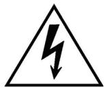
Front View
Illustration 2.1: TG-5/TG-7 front view
1 LC-Display (with controls)
2 Muting Indicator (MUTE) for channels A and B
3 Protections Indicator (PROTECT) for channels A and B
4 Input Level Control (CH A, CH B) for channels A and B
5 Level Indicators for channels A and B
6 Audio Input Mode Indicator (PARALLEL)
7 Power Amplifier Mode Indicator (BRIDGED)
8 Input Sensitivity/Gain Indicator (0dBu, 35dB, 32dB)
9 Remote Amplifier Indicator (IRIS-Net)
10 Standby Indicator (STANDBY)
11 Power On/Off Indicator (POWER)
12 Mains Switch
Rear View

Illustration 2.2: TG-5/TG-7 rear view
1 PowerCon® Mains Input (MAINS IN)
2 SpeakonTM Female-Type Power Amp Outputs (CH A, CH B)
3 Power Amp Output Terminals (CHANNEL A, CHANNEL B, BRIDGED)
4 Expansion Slot
5 XLR and Phoenix-Type Audio Inputs (IN A, IN B)
6 Input Sensitivity/Gain Switch
7 Audio Inputs Routing Switch (ROUTING)
8 Fan
9 Power Amp Outputs Mode Switch (MODE)
10 XLR-Type Audio Outputs (OUT A, OUT B)
11 Ground Lift Switch (CIRCUIT TO CHASSIS SWITCH)
12 Type Plate
Factory Settings
Table 2.1: Factory Settings of the Controls
| Control | Setting |
| Mains Switch | off |
| Level CH A | 0dB |
| Level CH B | 0dB |
Table 2.2: Factory Settings of the LC-Display
| Parameter | Value |
| Power-On-Delay | 0.00 s |
| Breaker Current (dependent on the mains) | 16 A (230 V) / 30 A (120 V) |
| Amplifier Name | Electro-Voice TG-5 or Electro-Voice TG-7 |
| LCD Contrast | 50% |
| LCD Brightness High | 90% |
| LCD Brightness Low | 40% |
| LCD Time to Dim | Autodim off |
| Temperature Unit | °C |
Table 2.3: Factory Settings of the Rear Panel Controls
| Controls | Setting |
| ROUTING | DUAL |
| MODE | NORMAL |
| SENSITIVITY/GAIN | 0dBu |
| GROUNDLIFT | GROUNDED |
2.2 Operating Voltage
The power amplifier receives its power supply via the MAINS IN connector, which is designed as a Neutrik PowerCon® connector
CAUTION:
The Powercon® is a connector without breaking capacity, i.e. the Powercon® should not be connected or disconnected under load or live.
During installation, always separate the power amplifier from the mains. Connect the power amplifier only to a mains network, which corresponds to the requirements indicated on the type plate.
TG-5
100-240 V~50-60 Hz
1000W
OUTPUT POWER
DUAL MODE: 2x1450 W/4 OHMS
BRIDGED MODE: 1x2900 W/8 OHMS
SERIAL:D170379JJMM 00000
TG-7
100-240 V~50-60 Hz
1450 W
OUTPUT POWER
DUAL MODE: 2x2500 W/4 OHMS
BRIDGED MODE: 1x5000 W/8 OHMS
SERIAL: D170378 JJMM 00000
Illustration 2.3: TG-5/TG-7 type plate
Table 2.4: Specifications for the Power Supply Unit
| Device | Voltage | Frequency | Power Consumption |
| TG-5 | 100-240 V | 50-60 Hz | 1000 W |
| TG-7 | 100-240 V | 50-60 Hz | 1450 W |
Mains Operation & Resulting Temperature
The following tables allow the determination of power supply and cabling requirements. The power drawn from the mains network is converted into output power to feed the connected loudspeaker systems and into heat. The difference between power consumption and dispensed power is called power dissipation (P_d) . The amount of heat resulting from power dissipation might remain inside of a rack-shelf and needs to be diverted using appropriate measures. The following table is meant as auxiliary means for calculating temperatures inside of a rack-shelf system/cabinet and the ventilation efforts necessary.
The column P_d lists the leakage power in relation to different operational states. The column BTU/hr lists the dispensed heat amount per hour.
| TG-5 | \(U_{mains}\) in V | \(I_{mains}\) in A | \(P_{mains}\) in W | \(P_{out}\) in W | \(P_d\ in\ W^1\) | BTU/hr2 |
| Idle | 230 | 0.7 | 70 | - | 70 | 239 |
| Max. Output Power @ 8 Ω3 | 230 | 15.3 | 2420 | 2 x 850 | 720 | 2457 |
| Max. Output Power @ 4 Ω3 | 230 | 25.7 | 4300 | 2 x 1450 | 1400 | 4777 |
| 1/3 Max. Output Power @ 4 Ω3 | 230 | 14.7 | 2325 | 2 x 483 | 1358 | 4635 |
| 1/8 Max. Output Power @ 4 Ω3 | 230 | 6.2 | 875 | 2 x 181 | 513 | 1749 |
| 1/8 Max. Output Power @ 4 Ω4 | 230 | 6.7 | 1000 | 2 x 181 | 588 | 2005 |
| 1/8 Max. Output Power @ 4 Ω45 | 253 | 7.1 | 1105 | 2 x 219 | 666 | 2274 |
| Normal Mode (-10 dB) @ 4 Ω3 | 230 | 5.6 | 775 | 2 x 145 | 485 | 1655 |
| Rated Output Power (0 dB) @ 4 Ω3 | 230 | 23.5 | 3900 | 2 x 1200 | 1500 | 5118 |
| Alert (Alarm) Mode (-3 dB) @ 4 Ω3 | 230 | 16.7 | 2665 | 2 x 600 | 1465 | 4999 |
| Max. Output Power @ 2 Ω3 | 230 | 39.6 | 6920 | 2 x 2000 | 2920 | 9963 |
| 1/8 Max. Output Power @ 2 Ω3 | 230 | 9.1 | 1345 | 2 x 238 | 870 | 2969 |
| 1/8 Max. Output Power @ 2 Ω4 | 230 | 9.1 | 1335 | 2 x 238 | 860 | 2934 |
| TG-7 | Umains in V | Imains in A | Pmains in W | Pout in W | Pd in W1 | BTU/hr2 |
| Idle | 230 | 0.7 | 78 | - | 78 | 266 |
| Max. Output Power @ 8 Ω3 | 230 | 24.5 | 4089 | 2 x 1500 | 1089 | 3716 |
| Max. Output Power @ 4 Ω3 | 230 | 40.9 | 7137 | 2 x 2500 | 2137 | 7292 |
| 1/3 Max. Output Power @ 4 Ω3 | 230 | 18.1 | 2927 | 2 x 833 | 1260 | 4300 |
| 1/8 Max. Output Power @ 4 Ω3 | 230 | 6.2 | 877 | 2 x 313 | 252 | 860 |
| 1/8 Max. Output Power @ 4 Ω4 | 230 | 9.6 | 1450 | 2 x 313 | 806 | 2750 |
| 1/8 Max. Output Power @ 4 Ω4 5 | 253 | 11.6 | 1944 | 2 x 378 | 1188 | 4053 |
| Normal Mode (-10 dB) @ 4 Ω3 | 230 | 9.2 | 1368 | 2 x 250 | 868 | 2962 |
| Rated Output Power (0 dB) @ 4 Ω3 | 230 | 37.5 | 6445 | 2 x 2100 | 2245 | 7660 |
| Alert (Alarm) Mode (-3 dB) @ 4 Ω3 | 230 | 22.7 | 3760 | 2 x 1050 | 1660 | 5664 |
| Max. Output Power @ 2 Ω3 | 230 | 44.3 | 8180 | 2 x 3500 | 1180 | 4026 |
| 1/8 Max. Output Power @ 2 Ω3 | 230 | 15.3 | 2427 | 2 x 438 | 1552 | 5296 |
| 1/8 Max. Output Power @ 2 Ω4 | 230 | 13.6 | 2105 | 2 x 438 | 1230 | 4197 |
- P_d = Power Dissipation
- 1BTU = 1055.06J = 1055.06Ws
- Sine Modulation (1 kHz)
- Pink-Noise EN60065/7Edition
- 10% Mains Over Voltage
The following factors allow direct proportional calculation of the mains current I_mains for different mains supply voltages: 100 V = 2.3 , 120 V = 1.9 , 220 V = 1.05 , 240 V = 0.97 .
2.3 Mains Switch
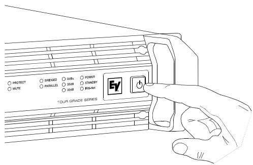
The Mains Switch on the front panel separates the power amp from the mains. Pressing the Mains Switch starts booting up the power amp. A soft start circuit compensates mains inrush current peaks and thus prevents the automatic cutout of the mains from reacting when switching on the power amplifier. Speaker system switch-on is delayed by approximately 2 seconds via output relays, effectively suppressing any possible power-on noise, which otherwise might be heard through the loudspeakers. MUTE-LED light during this delay.
2.4 Mounting
Front Mounting of the Power Amplifier
TOUR GRADE amplifiers have been designed for installation in a conventional 19-inch rack case. Attach the power amp with its frontal rack mount ears using 4 screws and washers as shown in illustration 2.4.
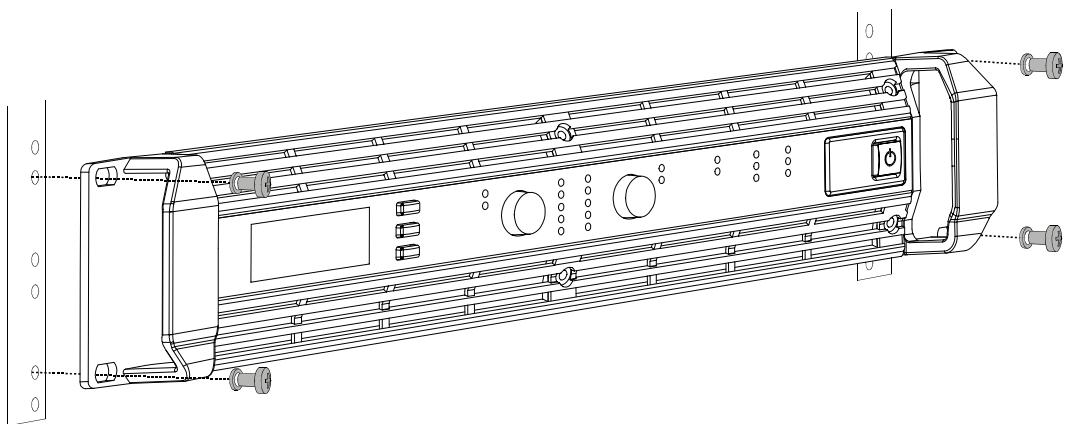
Illustration 2.4: Front mounting when installing the power amplifier in a rack case
Rear Mounting
Additionally securing the amplifier at the rear becomes necessary, if the rack case in which the power amplifier has been installed will be transported. Failure to do so may result in damage to the power amplifier as well as to the rack case. Brackets for securing the power amplifier are supplied. Attach the power amp as shown in illustration 2.5 using the supplied 4 case nuts and screws.
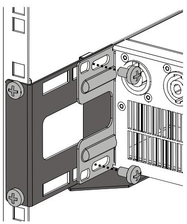
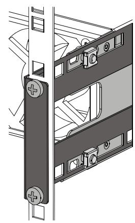
Illustration 2.5: Rear mounting when installing the power amplifier in a rack case
2.5 Ventilation
As with all Electro-Voice power amps with fan cooling, the airflow direction is front-to-rear, obviously because there is more cold air outside of the rack case than inside. The power amplifier remains cooler and dissipating the developing waste heat in a specific direction gets easier. In general, setting up or mounting the power amplifier has to be done in a way that fresh air can enter unhindered at the front and exhausted air can exit at the rear. When installing the power amp in a case or rack system, attention should be paid to these details
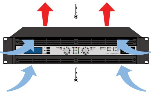
Illustration 2.6: TG-5/TG-7 Kuhlung
to provide sufficient ventilation. Allow for an air duct of at least 60~mm × 330~mm between the rear panel of the power amplifier and the inner wall of the cabinet/rack case. Make sure that the duct reaches up to the cabinet's or the rack case's top ventilation louvers. Leave room of at least 100~mm above the cabinet/rack case for ventilation. Since temperatures inside of the cabinet/rack case can easily rise up to 40^ during operation of the power amp, it is mandatory to bear in mind the maximum allowable ambient temperature for all other appliances installed in the same cabinet/rack case.
CAUTION:
Blocking/closing the power amp's ventilation louvers is not permissible. Without sufficient cooling/ventilation, the power amplifier may automatically enter protect mode. Keep ventilation louvers free from dust to ensure unhindered airflow.
CAUTION:
Do not use the power amplifier near heat sources, like heater blowers, stoves or any other heat radiating devices.
CAUTION:
To ensure trouble-free operation, make certain that the maximum allowable ambient temperature of +40^ is not exceeded.
For fixed amplifier installations in a device control room that incorporate a central air-cooling system or air conditioners, calculating the maximum heat emission may be necessary. Please also take notice of the information on page 10.
2.6 Groundlift
The ground lift switch allows eliminating noise loops. When operating the power amplifier together with other equipment in a rack case, setting the switch to the GROUNDED position is recommended. Set the switch to UNGROUNDED, when the power amplifier is operated together with appliances with differing ground potentials.
2.7 Indication of the Operation Mode
Two LEDs on the power amp's front panel indicate the currently selected mode of operation. The PARALLEL-LED lights yellow, when the ROUTING switch is set to PARALLEL. The PARALLEL LED does not light, when the switch is set to DUAL. The BRIDGED LED lights yellow, when the MODE switch is set to BRIDGED. The BRIDGED LED does not light, when the switch is set to NORMAL.
2.8 Selecting the Mode Of Operation
ROUTING
The ROUTING switch on the power amp's rear panel defines how the audio inputs handle the input signals.
DUAL
In DUAL mode, the two channels of the power amplifier work independent from each other. This mode of operation is being used for all 2-channel applications, like stereo or Bi-Amp (active) operation. Using the input level controls on the power amp's front panel or an optionally available remote control module and IRIS-Net™ allows independently adjusting the channels' amplification.
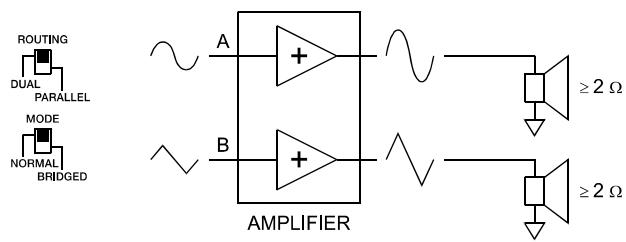
Illustration 2.7: Audio signal applied to both input connectors in DUAL mode
PARALLEL
In PARALLEL mode, the inputs of channel A and channel B are directly electrically linked. The audio signal has to be applied to the input connectors (XLR or Phoenix) of channel A. Using the input level controls or IRIS-Net™ to independently control the amplification of the two channels is still possible because only the channels' inputs are linked. PARALLEL operation is the mode of choice, whenever the same input signal drives multiple power amp channels of a large system installation, e.g. when driving massive bass arrays.
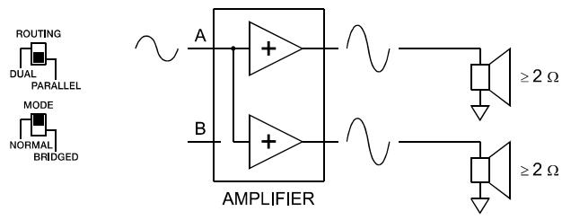
Illustration 2.8: Audio signal applied to input connector A in PARALLEL mode
CAUTION: In PARALLEL mode, the input signal has to be fed to input channel A only.
MODE
The MODE switch on the power amp's rear panel defines the operation mode of the power amplifier blocks and thus, how a single or more speaker systems have to be connected.
NORMAL
In two-channel operation (NORMAL), both power amplifier blocks work as independent power amp channels and controlling the amplification of each channel separately is possible. How the power amp's audio inputs handle input signals depends only on the setting of the ROUTING switch.
BRIDGED
In BRIDGED mode, the power amplifier functions as single-channel, monaural power amp. The audio signal has to be applied to either one of the input connectors (XLR or Phoenix) of channel A while channel B inputs are inactive. In BRIDGED mode, the power amp channel A is modulated as usual. In addition, the input signal is internally inverted and applied to channel B. The A and B power amps act in push-pull operation delivering doubled output voltage.
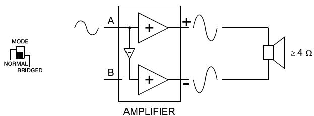
Illustration 2.9: BRIDGED mode
CAUTION:
In BRIDGED mode operation, it is not allowable for the load connected to fall below a value of 4 ohms. Extremely high voltages can be present at the output. The connected speaker systems must be able to handle such voltages. Make sure to completely read and fully observe power rating specifications of the speaker systems to be used and to check them against the output power capacity of the power amp.
SENSITIVITY/GAIN
TOUR GRADE SERIES amplifiers can be operated at an input sensitivity of 0dBu as well as at a constant gain of 35dB or 32dB. A correspondingly labeled LED on the power amp's front panel indicates the respective setting of the sensitivity/gain switch, which is located on the power amp's rear panel.
NOTE:
If a remote control module is used the sensitivity/gain switch is deactivated and the sensitivity/gain of the amplifier is automatically set to 35 dB.
An Input sensitivity of 0dBu means that with an input signal of 0 dBu (0.775 Vrms), the signal at the power amplifier outputs is at Rated Output Power. This setting is recommended for audio signal sources that deliver a nominal output voltage of 0 dBu. As an alternative, operating the power amp at a constant gain of 35 dB or 32 dB is also possible. Operating all power amps in a setup – even those of different performance classes – at constant gain setting greatly simplifies the adjustment of signal processors. This allows the installer to consider each power amplifier with a gain of 35 dB (or 32 dB) when setting gain structure, independent of the actual maximum output capacity of each individual power amp. Any limiters have to be adjusted to maximum power handling capacity of the loudspeaker components.
Audio Cabling
Input (XLR / Phoenix)
Inputs IN A and IN B are electronically balanced and the SENSITIVITY switch controls input sensitivity. Connection can be established either by using XLR- or Phoenix-type connectors, which are connected in parallel. The needed Phoenix-type connectors are supplied with the power amplifier. The pin-assignment of XLRF-type connectors is in accordance with the IEC standard 268.
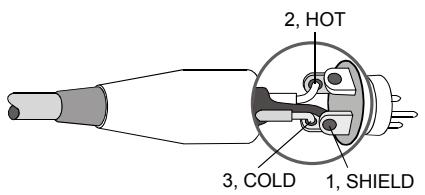
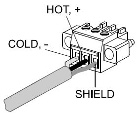
Illustration 2.10: Balanced connection of input
Whenever possible, using balanced audio signal feeds at the input of the power amplifier is always preferred. Unbalanced connections should only be used if the cables are very short and no interfering signals are to be expected in the vicinity of the power amplifier. In this case, bridging the screen (shielding) and the pin of the inverting input inside of the connector is mandatory. Otherwise, a 6 dB drop in level could result. Please also see illustration 2.11. Due to their immunity against external interference sources, such as dimmers, mains connections, HF-control lines, etc., using balanced cabling and connections is always preferable.
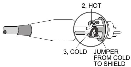
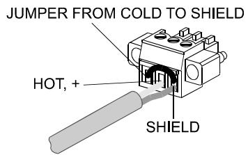
Illustration 2.11: Unbalanced connection of input
Next to its input connector, each channel provides an individual XLR-type connector (OUT A or OUT B), which is connected in parallel to allow for comfortably daisy-chaining the audio signal for the connection of additional audio equipment.
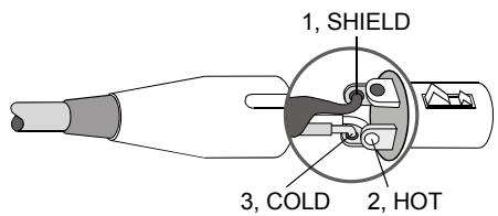
Illustration 2.12: Balanced connection of output (Daisy-Chain)
Output (Speakon-type Connectors / Terminals) in Normal Mode
With TOUR GRADE amplifiers speaker connection differs depending on the actually selected mode of operation of the power amplifier blocks, i.e. the setting of the MODE switch on the power amp's rear panel. In NORMAL mode, the loudspeaker systems can be connected in two different ways: using typical Speaker Systems Cabling or Bi-Amp Cabling.
Typical Speaker System Cabling
The first possibility is to use the two Speakon-type connectors, whereas speakers have to be connected to pins 1+ and 1- of the sockets, see illustration 2.13.
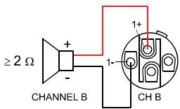

Illustration 2.13: Speaker connection in NORMAL operation mode, using Speakon A and B connectors
Table 2.5: Speaker connection in NORMAL operation mode, using Speakon A and B connectors
| Speakon CH B | Speakon CH A | |||
| 1+ | 1- | Connector | 1+ | 1- |
| B+ | B- | Assignment | A+ | A- |
Next to the Speakon-type sockets, conventional speaker terminals are provided as well. The following illustration shows how to connect the speaker systems for NORMAL mode operation.
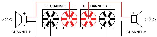
Illustration 2.14: Speaker connection in NORMAL operation mode, using Terminals
Bi-Amp Cabling
The second possibility for connecting the speakers when the power amplifier is operated in NORMAL mode is to only use the Speakon-type connector CH A and to connect one speaker cabinet to pins 1+ and 1-, as described above and the second cabinet to pins 2+ and 2- as shown in illustration 2.15. Only pins 2+ and 2- of the Speakon CH A connector are assigned. Proceeding like this facilitates the cabling of speaker systems that are used in active 2-way operation (Bi-Amp).
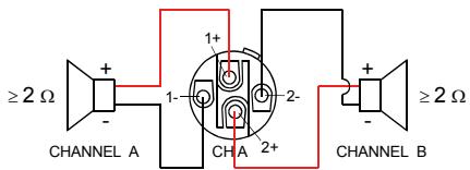
Illustration 2.15: Bi-Amp speaker connection in NORMAL operation mode, using only the Speakon A connector
Table 2.6: Bi-Amp speaker connection in NORMAL operation mode, using only the Speakon A connector
| Speakon CH A | ||||
| Connection Pin | 1+ | 1- | 2+ | 2- |
| Channel Assignment | A+ | A- | B+ | B- |
Output (Speakon-type Connectors / Terminals) in Bridged Mode
Setting the MODE switch on the power amp's rear panel to BRIDGED lets the power amplifier run in bridged mode operation and speaker connection has to be established using pins 1+ and 2+ of the Speakon socket CH A, see illustration 2.16.
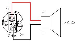
Illustration 2.16: Speaker connection in BRIDGED operation mode, using Speakon A
Table 2.7: Speaker connection in BRIDGED operation mode, using Speakon A
| Speakon CH A | ||
| Connection Pin | 1+ | 2+ |
| Channel Assignment | Bridged+ | Bridged- |
When using the speaker terminals in BRIDGED mode, the loudspeaker system has to be connected to the red terminals of CHANNEL A and CHANNEL B. An illustration of how to correctly establish speaker connection for this mode of operation is provided on the power amp's enclosure.
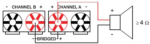
Illustration 2.17: Speaker connection in BRIDGED operation mode, using Terminals
CAUTION:
Due to the high current, using banana plugs for speaker connection is not permissible.
3 Operation
3.1 Volume Control
In DUAL and PARALLEL mode, the level controls CH A and CH B on the power amp's front panel are used to control the amplification of the corresponding channel. Turning the control to the right increases and turning it to the left decreases the volume. In BRIDGED mode operation, the output volume of the power amp is only controlled by the CH A level control. Any changes in the setting of the CH B level control are ignored.
With an installed remote control module, the level controls CH A and CH B may be deactivated, i.e. controlling the power amp's amplification is only possible via IRIS-Net™. The Level Controls Off! indicator on the graphical LC display signals that the controls are deactivated.
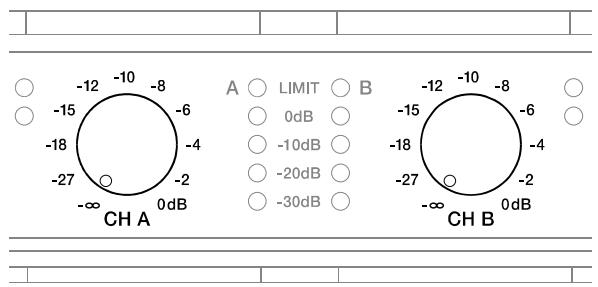
Illustration 3.1: Level controls CH A and CH B
3.2 Graphical LC display
The graphical LC display provides detailed information about the operating status of the power amplifier. Furthermore, it is possible to change several settings of the power amp and, if installed, of a remote control module.
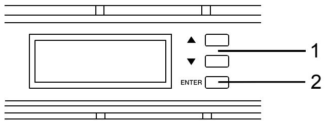
Illustration 3.2: LC display with controls
1 Up / Down buttons: These keys allow navigating through the menu.
2 ENTER button: Pressing this key selects the highlighted menu entry.
Power Amplifier Menu Navigation
Start screen and type designation appear after switching the power amplifier on. The power amp's status display appears after a few seconds. The top line always shows the name of the power amplifier. An overview of the power amp's actual condition is provided in lines two and three. Additional information is shown if, for example, a RCM-26 has been installed in the power amplifier.


Illustration 3.3: Status display of the power amplifier without / with RCM-26 installed (example)
Using the Up/Down buttons lets you scroll through the bottom line. The following table lists the information, which is displayed in consecutive order.
Table 3.1: Overview status display
| CAN Addr 3, 62.5kBd | Set CAN address and CAN baud rate (only with RCM-26 installed) |
| F1 linear thru facto | Name of the actual preset (only with RCM-26 installed) |
| Audio-Input Analog | Currently used audio input of the power amp (only with RCM-26 installed) |
| Level Controls off ! | Status of the input level controls on the power amp's front panel (only with RCM-26 installed) |
| 226U 0.7A 30°C | Mains voltage, mains current consumption (RMS) and amp temperature. |
| Dual 0dBu 17A | Currently active parameters for the mode of operation, sensitivity and Mains Circuit Breaker Protection |
| On-Delay: 0.15 s | Power-on delay of the power amp |
| Breaker: 16 A | Actual parameter for the Mains Circuit Breaker Protection |
| >> ENTER CONFIG << | Pressing the ENTER button branches to the CONFIG configuration menu. |
The following illustration shows the structure of the CONFIG menu (and its associated submenus) when opening it from the status display. Menu entries marked with an asterisk * are only available when the remote control module is not installed.
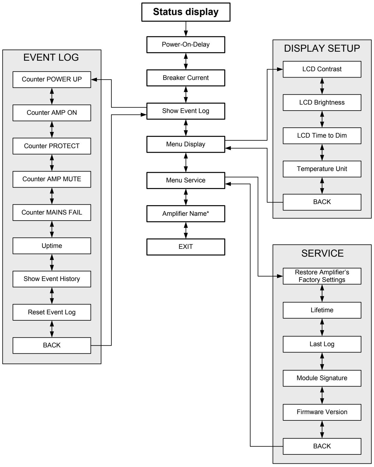
Illustration 3.4: The power amp's menu structure
Structure of the CONFIG menu
Entering the CONFIG menu is possible through pressing the ENTER button while the entry >> CONFIG << is highlighted in the status display. The following provides detailed information about the individual items of the configuration menu.
CONFIG/Power-On-Delay: The power amp's currently set power-on delay is shown. Pressing the ENTER button opens the Set Power-On-Delay dialog box.
Using the Up/Down buttons in the Set Power-On-Delay lets the user specify a delay in the range of 0 seconds to up to 6.35 seconds. Pressing the ENTER button again stores the previously made setting and the display returns to the CONFIG menu.


CONFIG/Breaker Current: The actually set value of the current that controls the Mains Circuit Breaker Protection is displayed. The set current has to match the value of the power amp's internal fuse for the protection to work correctly. Please refer to the explanations on page 32 for more details. Pressing the ENTER button opens the Set Breaker Current dialog box where the desired value for the breaker current can be set.
The valid value ranges depend on the power amp's power supply. Currents between 6 A and 40 A can be set when the power amplifier is operated at 120 V. Currents between 6 A and 30 A can be set when the power amplifier is operated at 220-240 V. Select Factory 30 A or Factory 16 A for automatic setting depending on the power amp's power supply. Pressing the ENTER button stores the selected current value in memory and the CONFIG menu reappears on the display.


NOTE: Operating the power amplifier on a separately fused mains power line is recommended only.
CONFIG/Show Event Log: The menu entry Show Event Log leads to the EVENT LOG submenu. The individual entries in the EVENT LOG menu are explained in detail in the paragraph Structure of the CONFIG/EVENT LOG menu (see page 23).

CONFIG/Menu Display: The menu entry Menu Display leads to the DISPLAY SETUP submenu. Each entry in the DISPLAY SETUP menu is explained in detail in paragraph Structure of the CONFIG/DISPLAY SETUP menu (see page 24).

CONFIG.Menu Service: The menu entry Menu Service branches to the SERVICE submenu. The entries in the SERVICE menu are explained in detail in paragraph Structure of the CONFIG/SERVICE menu (see page 26).

CONFIG/Amplifier Name: Displays the name of the power amplifier. The menu entry only exists when no RCM-26 is installed in the power amplifier. With a remote control module installed, the power amplifier has to be named via IRIS-Net™. Pressing the ENTER button opens the Set Amplifier Name dialog box.
The Set Amplifier Name dialog allows changing the power amp's name, which can be composed of a maximum of 20 symbols and consist of all letters a-z, A-Z, the numbers 0-9 and special characters.
Pressing the Up/Down buttons locates the cursor at the desired position of the name. Pressing the ENTER button accepts the desired symbol and moves the cursor to the next character. Pressing the ENTER button after manipulating the last character, stores the desired name of the power amplifier in the memory and the display returns to the CONFIG menu.
The following special characters provide special functions when entering a power amp's name:


Table 3.2: Functions of special characters when entering the power amp's name
| Character | Function |
| \(\leftarrow\) | Accepts the entered name and returns to the menu. |
| ■ | Deletes the currently selected symbol and moves the cursor by one character to the right. |
| \(\downharpoonright\) | Set the cursor by one character to the left. |
Structure of the CONFIG/EVENT LOG menu
CONFIG/EVENT LOG/Counter POWER UP: This menu item shows how many times the power switch on the front panel has been used.

CONFIG/EVENT LOG/Counter AMP ON: This menu item shows how often the power amplifier has been activated from the OFF or STANDBY state.

CONFIG/EVENT LOG/Counter PROTECT: This item shows how many times one of the protections has been activated.

CONFIG/EVENT LOG/Counter AMP MUTE: This menu item shows how often the power amp's output signal has been muted by one of the protections.

CONFIG/EVENT LOG/Counter MAINS FAIL: This menu item shows how many times over- or undervoltage has been recognized at the power amp's power supply unit.

CONFIG/EVENT LOG/Uptime: This menu item shows the total running time of the power amplifier (not counting standby times) since the last reset of the Event Log.

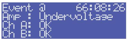
CONFIG/EVENT LOG/Show Event History: The Show Event History menu entry opens a list of all events in chronological order (last event shown first) that have been registered. Pressing the ENTER button selects the desired item in the list.

Point in time and cause of the occurrence is shown for each item in the list. The state of operation of the amplifier (Amp) and the two output channels (Ch A or Ch B) is indicated for each event. Pressing the Up/Down buttons lets the user scroll through the list of entries. Pressing the ENTER button lets one return to the CONFIG menu.
CONFIG/EVENT LOG/Reset Event Log: The user can completely reset the Event Log of the power amplifier in this menu entry. All counters are reset to zero and the event log is deleted. Pressing the ENTER button opens a safety dialog box that lets the user choose between YES or NO by pressing the Up/Down buttons. If YES has been selected, pressing the ENTER button resets the Event Log. If the user decides to select NO, the Event Log stays unchanged and the CONFIG. menu reappears on the display.

Structure of the CONFIG/DISPLAY SETUP menu
CONFIG/DISPLAY SETUP/LCD Contrast: This menu item indicates the currently set contrast of the LC display. Pressing the ENTER button opens the Set LCD Contrast where the user can select a contrast setting in the range of 0 % to 100 % by using the Up/Down buttons. Pressing the ENTER button again stores the selected value for contrast in memory and the CONFIG menu reappears on the display.


CONFIG/DISPLAY SETUP/LCD Brightness: The currently set maximum and minimum values for display brightness are indicated. The maximum value represents the brightness of the display that is used during normal operation. The minimum value represents the brightness of the display that it is adjusted to after a specific period of time, if desired.
Pressing the ENTER button opens the Set Brightn. Hi-Lv1 dialog box, which, by pressing the Up/Down buttons, allows setting the undimmed display brightness in a range of 50 % to 100 % .
Pressing the ENTER button stores the set brightness value in memory and the display indication changes to the Set Brightn. Lo-Lv1 dialog box, where pressing the Up/Down buttons allows setting the dimmed display brightness in a range of 0% to 80% . Pressing the ENTER button again stores the set brightness value and the display returns to the CONFIG menu.


CONFIG/DISPLAY SETUP/LCD Time to Dim: The currently set time interval, during which the display lights with the maximum brightness it has been set to, is indicated. After the time interval has expired, the display is dimmed.
Pressing the ENTER button opens the Set LCD Time to Dim dialog box, where the user can specify the duration after which the display dimming starts by pressing the Up/Down buttons. The duration can be set to 4, 8, 16, 32 or 64 minutes. Alternately, the user can select Autodim off to completely deactivate the dimming function, which results in the display always lighting at the set maximum brightness level (Brightn. Hi-Lvl).


For an increased lifetime of the display, activating the dimming function is recommended. Pressing the ENTER button stores the settings in memory and the display returns to the CONFIG menu.
CONFIG/DISPLAY SETUP/Temperature Unit: The currently selected unit for the indication of temperature values is displayed.
Pressing the ENTER button opens the Set Temperature Unit dialog box, which allows selecting ^ C (Degrees Celsius) or ^ F (Degrees Fahrenheit) by pressing the Up/Down buttons. Pressing the ENTER button stores the selected unit in memory and the CONFIG menu reappears on the display.


Structure of the CONFIG/SERVICE menu
CONFIG/SERVICE/Restore Amplifier's Factory Settings: The power amplifier can be reset to factory settings. Pressing the ENTER button opens a safety dialog box that lets the user choose between YES or NO by pressing the Up/Down buttons. If YES has been selected, pressing the ENTER button resets the power amplifier to its factory settings. If the user selected NO, all power amp parameters stay unchanged and the display returns to the CONFIG. menu.

The following table lists all parameters that are affected by a reset:
Table 3.3: Factory settings of the LC display
| Parameter | Value |
| Power-On-Delay | 0.00 s |
| Breaker Current (depends on the supply voltage) | 16 A (230 V) / 30 A (120 V) |
| Amplifier Name | Electro-Voice TG-5 or Electro-Voice TG-7 |
| LCD Contrast | 50 % |
| LCD Brightness High | 90 % |
| LCD Brightness Low | 40 % |
| LCD Time to Dim | Autodim off |
| Temperature Unit | °C |
CONFIG/SERVICE/Lifetime: This menu item shows the total running time of the power amplifier (not counting standby times).

CONFIG/SERVICE/Last Log: Shows point in time and type of the last entry in the event history. If service is needed, the code shown here provides relevant detail of what might have caused the malfunction for your Electro-Voice Service partner.

CONFIG/SERVICE/Module Signature: In the event of failure or malfunction, the information shown here provides relevant detail of what might have caused the malfunction for your Electro-Voice Service partner.

CONFIG/SERVICE/Firmware Version: This menu item shows version and date of the firmware that is actually installed in the power amplifier.

Structure of the MODULE CONFIG menu
The MODULE CONFIG menu provides access to RCM-26 remote control module settings, which are available from the LC display of the power amplifier. This menu cannot be accessed during operation of the power amplifier. Accessing this menu is only possible when the power amp is switched off.
The following steps open the MODULE CONFIG menu:
- If the power amplifier is powered on or in standby mode, use the mains switch on the front panel to switch the power amp off.
- Simultaneously press the and ENTER buttons and keep them pressed.
- Use the power switch on the front panel to switch the power amplifier on.
The power amp enters standby mode and the MODULE CONFIG menu appears on the display.

Illustration 3.5 shows the structure of the MODULE CONFIG menu of a TOUR GRADE SERIES amplifier with a installed RCM-26 remote control module.
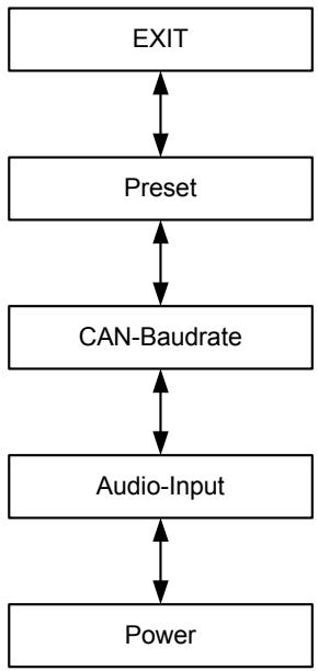
Illustration 3.5: Structure of the Module Config menu (RCM-26)
The following provides detailed information about the individual items of the MODULE CONFIG menu.
MODULE CONFIG/Preset: The name of the currently active preset is displayed. Pressing the ENTER button opens the Load Preset dialog box, which allows the user to select a preset by pressing the Up/Down buttons.
Pressing the ENTER button opens a safety dialog box, which lets the user select whether he actually wants to load the selected preset by pressing the Up/Down buttons to either select YES or NO. When YES has been selected, pressing the ENTER button loads the selected preset and the display returns to the MODULE CONFIG menu. When NO has been selected, the selected preset is not loaded. The power amp's currently active preset is not changed and the MODULE CONFIG menu reappears on the display.


CAUTION:
The selected preset must be suitable for the use with the connected loudspeaker components. An incorrectly adjusted preset or incompatible preset can cause serious damage to the connected speaker systems.
MODULE CONFIG/CAN-Baudrate: The currently set CAN baud rate of the RCM-26 is indicated. Pressing the ENTER button opens the Set CAN-Baudrate dialog box, which by pressing the Up/Down buttons, lets the user select one of the following CAN baud rates: 10kBaud, 20kBaud, 62.5kBaud, 125kBaud, 250kBaud or 500kBaud.
Pressing the ENTER button stores the selected baud rate in memory and the display returns to the MODULE CONFIG menu.


CAUTION:
All devices on a specific CAN-BUS must be set to the same baud rate.
MODULE CONFIG/Audio-Input: The currently used audio input is indicated. Pressing the ENTER button opens the Select Audio-Input dialog box, which, by pressing the Up/Down buttons, allows selecting Analog or AES/EBU inputs. Pressing the ENTER button stores the desired input in memory and the display returns to the MODULE CONFIG menu.


MODULE CONFIG/Power: The power amp's actual operating status after using the mains switch is displayed.
If standby mode has been activated via IRIS-Net™ and the power amplifier has been switched off using the mains switch, the power amp automatically restarts into standby mode the next time it is switched on by pressing the mains switch. This menu item allows booting the power amplifier out of standby mode, even without IRIS-Net™.

Pressing the ENTER button opens the Set Power dialog box, which allows the selection of On or Standby operating states by pressing the Up/Down buttons. Pressing the ENTER button stores the desired status in memory and the MODULE CONFIG menu reappears on the display.

3.3 Indications
PROTECT
Whenever the PROTECT-LED lights yellow, one of the internal protections has been activated. However, a lit PROTECT-LED does not necessarily mean that the signal path gets switched off. The differentiated protections concept of TOUR GRADE SERIES power amps results in several protection circuits being activated one after another, which ensures that under normal circumstances the power amplifier will stay in the safe and stabile operating range. In case the amplifier needs to be switched off to prevent power amplifier and connected speaker systems from being damaged, this is indicated by the PROTECT and MUTE-LEDs being lit simultaneously.
MUTE
The MUTE-LED lights red whenever the power amp's output signal is being muted, which happens for example during power-on delay of the speaker systems, when switching the input sensitivity, and when manually muting the output signal via IRIS-Net™.
-30dB...LIMIT
Level indication is realized via two vertical LED chains on the power amp's front panel that individually indicate the actual levels of each channel at -30dB, -20dB, -10dB below full modulation and 0dB as soon as full modulation is reached. 0 dB indication results from comparing the power amp's internal ratio of input to output voltage, which ensures precise indication of the full modulation limit, even before limiting becomes audible. If the input audio signal is driven above the 0 dB mark, a clipping limiter reliably controls distortion down to a stable rate of 1% . The red LIMIT-LED has a dynamic brightness control that makes it easy to perceive the degree of limiting applied to the signal.
POWER
The POWER-LED lights green when the power amplifier is on. If the POWER-LED does not light, despite the fact that the amplifier has been switched on, this indicates that the power amp is not connected to the mains, the primary fuse has blown, or the amplifier is in standby mode (the STANDBY-LED lights yellow). The POWER-LED blinks whenever the voltage at the MAINS IN is too high (overvoltage) or too low (undervoltage), which prevents that the power amplifier can be switched on.
STANDBY
The STANDBY-LED lights yellow when the power amp is in standby mode. Standby mode reduces the amp's power consumption to an absolute minimum. Activating the standby mode is only possible via IRIS-Net™. Deactivating the standby mode is possible via IRIS-Net™ as well as directly on the power amplifier. For deactivating the standby mode, select Power from the Module Config menu (see page 29).
IRIS-Net
The IRIS-Net-LED lights blue if an IRIS-Net™-compatible remote control module has been installed in the power amp's extension slot and successful data communication has been established. All LEDs blink slowly whenever the "Find" function in IRIS-Net™ is being used to locate a power amplifier in the rack. Deactivate „Find" function via IRIS-Net™ or press any key at the amplifiers front.
3.4 Fan Cooling
The power amplifier has two fans on the front and one on the rear. The fans are switched in five performance-optimized levels, i.e. they are not running permanently but the running speed of each fan is individually controlled depending on the ambient temperature. That in return ensures very silent running during idle state. The temperatures of the power amp's two channels and of the power supply unit are registered and monitored separately. The intelligent and processor-controlled fan-control activates a fan to run exactly at the level that is needed to cool down the corresponding components. This concept effectively prevents the needless "rev up" of the fans when in idling state as well as the occurrence of a thermally balanced condition, which causes permanent noise-intensive running of the fans. In other words, the fans are activated only when it is really necessary because of thermal conditions.
3.5 Protections
In case one of the power amp's internal protections responds during operation, a corresponding message appears on the LC display (or the PROTECT-LED lights) and an entry containing date, time, and protection type is created in the event log.
True RMS Mains Voltage and Current Measurement
TOUR GRADE SERIES amplifiers are consistently informed about the state of the mains network that they are connected to. The CPU of the power amplifier continually computes the current RMS (Root Mean Square, effective value) of the mains voltage and the mains current consumption. This genuine RMS measurement has substantial advantages over the commonly used peak value measurement:
- Mains voltage measurement functions reliably even with non-sinusoidal mains networks, which, for example, can be found with a generator-powered amplifier or when the mains voltage situation becomes unstable.
- Mains voltage measurement is insusceptible to transient mains interference, as can occur when switching inductive loads such as large electric motors
- True mains current RMS measurement allows the precise matching of the power consumption to the characteristics of a mains circuit breaker. Detailed information about the adjustable Mains Circuit Breaker Protection function is provided in the following paragraph.
RMS measurement permanently protects the power amplifier against mains over or undervoltage. At the occurrence of extreme mains overvoltage, the power amp switches off to prevent severe damage. Switching on the power amp is not possible whenever mains overvoltage has been detected. The mains voltage monitoring protection switches the power amplifier off at the occurrence of extreme mains undervoltage (less than 70 V AC). In both cases, the blinking POWER-LED indicates the fault condition. In
case of power outage, both output channels are instantly muted then the power amplifier is shut down within only a few milliseconds.
Mains Circuit Breaker Protection
The power amplifier automatically reduces the output power whenever it is driven at high levels with extremely low-impedance loads connected, resulting in the chance that the mains circuit breaker reacts. Therefore, adjusting the characteristics of the utilized circuit breaker in Amperes is possible via the LC display. Especially at extremely high/low ambient temperatures or when connecting the power amplifier together with other equipment to a single common automatic circuit breaker, it might become necessary to manually set an Ampere value that differs from the circuit breaker's nominal value to ensure that the Mains Circuit Breaker Protection functions optimally. The following table outlines the allowable value ranges and default settings for the two modes of operation at 120 V and 220-240 V.
Table 3.4: Mains Circuit Breaker Protection
| Operation | Minimum | Maximum | Factory Settings |
| 120 V | 6 A | 40 A | 30 A |
| 220-240 V | 6 A | 30 A | 16 A |
The power amp's CPU is acquainted with the temporal progression of the mains current consumption and therefore can simulate the typical behavior of a mains circuit breaker. Nevertheless, pulse peaks allow crest currents that can exceed the nominal value by a multiple. RMS measurement of the mains current consumption allows the CPU to emulate the temperature curve of a circuit breaker's thermal trip, which in return enables the Mains Circuit Breaker Protection to let the power amplifier work till shortly below the trigger level of the automatic circuit breaker. With typical concepts, especially for those without RMS current measurement, output power reduction has to be applied much earlier. During the processing of musical program material, the Mains Circuit Breaker Protection normally does not have to reduce the power amp's output power. At most, with settings that are noticeably below the pre-set values of 16 A or 30 A respectively, (which may be reasonable when operating multiple power amps via a single automatic circuit breaker) output power reduction might become necessary to prevent the mains fuse from blowing.
A Power-On Delay of up to 6.35 seconds can be programmed for the power amp via the LC display. Upon pressing the mains switch the power amplifier does not start until the set delay time has elapsed. If several power amps are operated on the same automatic circuit breaker, cascaded switch-on can be accomplish by programming individually different power-on delays for the amps. This also prevents the magnetic trip of an automatic circuit breaker from acting and thus disconnecting the power amplifiers from the mains supply, when various amps are switched on at the same time. The internal soft-start function additionally suppresses current peaks during power-on, which ensures trouble-free operation of TOUR GRADE SERIES amplifiers even on very sensitive automatic circuit breakers.
Output Short Circuit Detection
The corresponding output voltage and output current is measured for both output channels as soon as the power amplifier processes an audio signal. These readings are used to monitor the connected loudspeaker loads. The power amplifier has the ability to continuously deliver very high output currents. For example, if, in spite of a low output voltage, the current flow is high as the consequence of a short-circuit in one of the speaker lines, the power amp detects this fault condition and immediately disables signal output to protect connectors and cables against damage from overload. This, of course, also protects the power amplifier itself from being damaged by excessive electrical or thermal overload.
Advanced Thermal Protection
The TOUR GRADE SERIES amplifiers are the first to feature the new Advanced Thermal Protection (ATP). This new system differs in a trend-setting manner from traditional thermal protection measures, which, as soon as the fans are not any longer capable of dissipating the lost heat, mostly switch off the entire signal path at a relative early stage. With the ATP system switching off the signal path is last of three consecutive measures. Prior to making this final step, the system uses two other approaches to limit the amp's power, so that it returns to a thermally stable operational range.
The first step is Voltage Limitation. This measure reduces the internal supply voltage of the power amplifier blocks, which, objectively is at the expense of reducing the voltage dynamic. During the reproduction of music or speech, however, this effect is subjectively hardly perceived. Despite the negligible acoustic influence, the efficiency gained in the power amp is so high that the development of heat is clearly reduced. As soon as the power amp's temperature returns to a non-critical state, the ATP system imperceptibly switches back to full supply voltage.
Thermal Limiter is the second measure that is only activated if, under extreme conditions, Voltage Limitation is not sufficient. The thermal limiter circuit unobtrusively reduces the amplification of the power amplifier. Only if even this measure does not re-establish thermal balance, the ATP system activates Thermal Mute as the last step to completely switch off the signal path.
This step-by-step functioning of Advanced Thermal Protection enables TOUR GRADE SERIES amplifiers to still be in operation under conditions where various other amps would have ceased operation.
The PROTECT-LED lights immediately to signal a direct intervention in the signal path by limiters and a corresponding indicator in IRIS-Net™ allows the FOH-engineer to react instantly, even before interference with the audio performance becomes noticeable.
Monitoring Ambient Temperature
TOUR GRADE SERIES amplifiers constantly monitor the temperature of several active electrical components during operation. In addition, monitoring also includes the temperature of the inlet cooling air and as a result also the temperature of the power amp's ambience. If, for any reason the ventilation louvers are totally blocked or the inlet outer air exceeds the upper temperature limit for effective cooling, this would inevitably lead to overheating of the power amplifier. This condition can possibly occur even when the power amplifier is in idling mode, for example when it is installed in a closed rack case.
However, during idling the preventive measures of the Advanced Thermal Protection (see previous paragraph) show hardly any impact. For this reason the power amplifier enters standby mode once it is operated under extreme thermal load, which is caused by inadequate cooling. In that case, PROTECT-LED and STANDBY-LED blink alternately.
The power amplifier automatically re-starts after approximately 20 minutes. As an alternative, re-starting the power amplifier manually using the mains switch or via IRIS-Net™ is also possible, if the device has cooled down sufficiently.
HF-Limiter
If the power amplifier processes high-frequency signals at high levels, amplification is automatically reduced after a while to protect the output stages against damage. Most of the time such conditions result from a malfunction in one of the devices that are connected upstream in the signal chain. The situation becomes particularly critical for power amplifier and connected tweeter cabinets when the signal is still in the audible range or just above the auditory threshold. Conventional HF-Protection circuits are not sensitive enough to react within this particular range, since they are primarily targeted at detecting fault conditions of the power amplifier itself.
Next to conventional HF-Protection, TOUR GRADE SERIES amplifiers have also a HF-Limiter, which is frequency-dependent and permanently monitors the output signal. The HF-L Limiter possesses the ability to reliably differentiate between normal reproduction of music and speech and critical operating conditions. The power amp's signal amplification is automatically reduced whenever such a critical operating condition occurs.
4 Options
Installing one of the optionally available extension modules in the extension slot on the rear panel lets you expand the power amp's functional range. As an example, the following paragraphs describe all aspects of the RCM-26 Remote Control Module in detail. Please read and follow the instructions provided in the owner's manuals that you have received together with each extension module.
4.1 RCM-26
System Description
The RCM-26 Remote Control Module is a two-channel digital controller module for live sound reinforcement, PA and fixed installation applications. Installing the RCM-26 turns a conventional amp into a remote amplifier, which, at any time, provides complete overview of the overall system status and control of all system parameters. RCM-26 modules allow the integration of TOUR GRADE amplifiers into a remote control network with up to 250 units. This offers the possibility to control and monitor an entire PA system from one or more PCs using the IRIS-Net™ - Intelligent Remote & Integrated Supervision - software package. All operational states, e.g. power-on status, temperature, modulation, limiting, activation of protections, deviation from the load impedance, etc., are centrally registered and displayed in IRIS-Net™. This provides the possibility to react and to selectively intervene even before critical operational states arise. Programming an automatic reaction, when specific thresholds are being exceeded or fallen below, is also possible.
With an RCM-26 installed, the integrated impedance testing function allows very precise monitoring of the connected loudspeaker systems. The impedance testing function utilizes the internal test tone signal generator and voltage/current measuring to determine the impedance of the loudspeaker systems including crossovers and cables over the entire frequency range. IRIS-Net™ plots an impedance curve of the measured impedance that can be compared with a formerly stored reference curve at any time. This reveals even smallest loudspeaker defects or deficiencies instantly. The impedance testing function is optimized for low impedance loads, like typical loudspeaker cabinets and/or loudspeaker components.
All parameters, like power on/off, level, muting, filters, etc. can be controlled in real-time and stored in the amplifier. Besides controlling and monitoring amplifiers, the RCM-26 also offers all conventional signal processing functions, like parametric equalizers, frequency crossovers, delays, compressors and limiters. Beyond that, linear-phase FIR-filters, zero-latency FIR-filters and digital speaker protection algorithms are available to optimize the amplifier and loudspeaker system. All DSP-settings can be freely edited and stored in user presets directly on the module. In the event of network failure or loss of power, all settings (filters, delay, level, etc.) stay intact, independent of the control by the network.
Furthermore, the RCM-26 provides a control port with freely programmable control inputs and control outputs. Control inputs (GPI's) allow the connection of switches. IRIS-Net™ offers the possibility to program a variety of logic functions for the inputs (e.g. switching to an alarm-preset with maximum energy in the speech area). Control outputs (GPO's) allow the connection of external components, which, for example, are used to signal specific states to peripheral equipment. Consequently, an amplifier with a RCM-26 module installed corresponds to highest safety requirements.
The RCM-26 has been designed with uncompromising audio quality in mind. Analog audio inputs (internally) and an AES3 (AES/EBU) digital audio input with XLR-type connector are provided. The use of the digital audio input offers a dynamic range of 128 dB. Using the analog audio input offers a dynamic range of 120 dB, which, by the way, is an absolute peak value for digital audio devices. For further details
about configuration, control and monitoring of amps with installed RCM-26 modules, please refer to the documentation of the IRIS-Net™ software.
Installation Notes
Installation
- Switch the power amp's power off and pull the mains plug
- Remove the cover panel from the rear panel (4 screws)
- Insert the RCM-26 module in the slot and lock it in place on the rear panel using the 4 screws (see illustration 4.1)
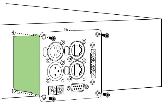
Illustration 4.1: Installation of a RCM-26
- Set the module's CAN-address using the ADDRESS selector switches
- Connect the needed interfaces (CAN, Audio, Control Port, RS-232)
- Reconnect the mains cord and switch on the power amplifier
- The power amp automatically recognizes the installed RCM-26 module
Conversion from Pre Fader Mode to Post Fader Mode
The RCM-26 is shipped from the factory in the recommended "Pre Fader" mode, so the input level controllers on the front of the amplifier are taken out of operation by installation of the RCM-26. If the input level controller are to be usable with a RCM-26 installed, the RCM-26 must be converted to "Post Fader" mode.
The conversion is done by changing the jumper settings of jumper JP1 to JP5 on the RCM-26. The following pictures show the jumper settings for "Pre Fader" mode and "Post Fader" mode. Only the jumper settings shown are allowed.
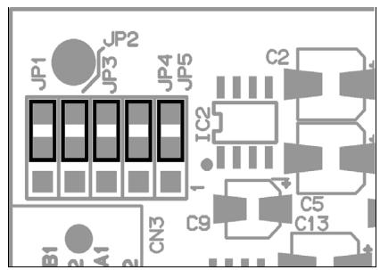
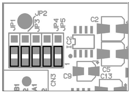
Illustration 4.2: Pre Fader mode (left) and Post Fader mode (right)
IRIS-NetTM
Configuring and controlling a remote amplifier with a RCM-26 module installed is possible through the use of IRIS-NetTM (Intelligent Remote & Integrated Supervision) PC-software. IRIS-NetTM allows programming the RCM-26 module's complete configuration while the computer is offline. All instructions on how to configure, operate and monitor all RCM-26 functions are included in the IRIS-NetTM help files.
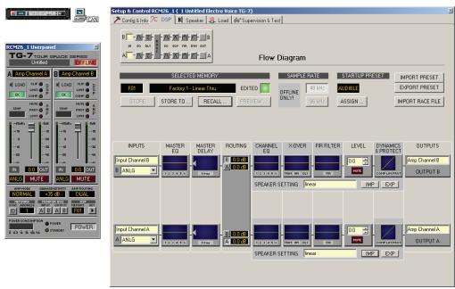
Illustration 4.3: DSP flow diagram of the RCM-26
Controls and Connections
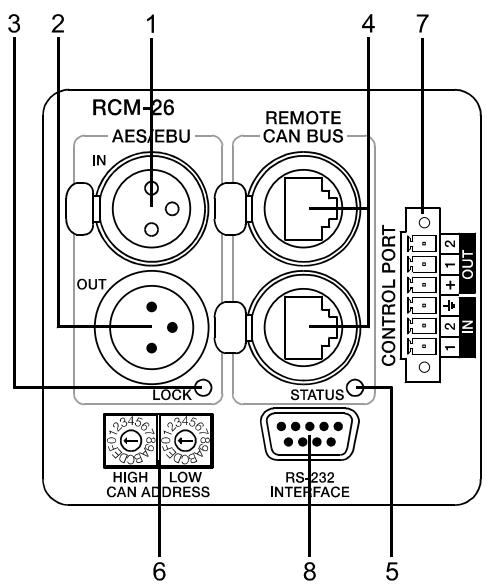
Illustration 4.4: Controls and Connections of the RCM-26
1 AES/EBU-IN
A digital AES/EBU input (AES3) is provided in addition to internal analog inputs. The digital input signal has to be connected to the AES/EBU IN connector. The AES/EBU input is a balanced transformer-isolated input. A sampling rate converter translates the input signal to match the internal sampling rate. However, the possibility to synchronize the RCM-26 to an external sampling rate exists as well. For further details, please refer to the IRIS-NetTM help files. Illustration 4.4 shows the pin-assignment of the input socket.
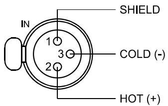
Illustration 4.5: Pin-assignment of AES/EBU-IN
2 AES/EBU-OUT
The AES/EBU OUT connector allows looping-through the digital audio signal to other RCM-26 modules. The digital input signal gets internally buffered and preprocessed (level matching / slew rate) before it is output via the OUTConnector. This allows fairly simple wiring between modules, without the need for AES/EBU distribution amps as they are usually used.
The RCM-26 has a bypass-relay, which, in case of damage (e.g. power outage), connects the AES/EBU IN signal through to AES/EBU OUT. This ensures trouble-free operation of downstream remote amps.
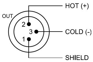
Illustration 4.6: Pin assignment of AES/EBU-OUT
3 LOCK-LED
LOCK
The LOCK-LED lights green as soon as the AES/EBU input has been synchronized to the incoming signal and thus proper audio transmission has been established. The LOCK-LED is dimmed with no digital audio signal being present at the input or the internal PLL not having
locked on to the incoming signal. The audio signal gets muted when the digital input has been selected.
4 REMOTE CAN BUS Connection
The RCM-26 module provides two Neutrik EtherCon® RJ-45 sockets for connecting to the REMOTE CAN BUS. These sockets are connected in parallel and serve as input as well as for daisy-chaining the devices on the remote network. Cabling in a rack system can be established using commercially available RJ-45 network cables. However, CAN guidelines have to be observed for longer cable lengths. Both ends of the CAN-bus must be terminated using 120 terminating plugs. For comprehensive information and instructions on cabling and bus length, please refer to the "CAN Bus principles" paragraph, starting on page 42. Along with the CAN bus, network cabling also carries a balanced audio monitoring signal. This monitor bus allows software-controlled monitoring of input or output signals of all power amps in the remote network, without the need for additional wiring. Nominal output level is +6 dBu (1.55 V) and maximum output level is +21 dBu (8.7 V).
The CAN bus allows using different data rates, whereas the data rate is inversely proportional to the bus length. For smaller network setups, data rates can be as high as 500 kbit/s. For broader networks, reducing the data rate becomes necessary (down to the minimum data rate of 10 kbit/s).
NOTE:
The data rate of the CAN Bus is preset to 10 kbit/s.
The following table illustrates the relation between data rate and bus length or network size. The use of CAN repeaters is strongly recommended for busses that exceed 1000 meters in length.
Table 4.1: Transfer rate and bus length
| Transfer rate (in kbit/s) | Bus length (in m) |
| 500 | 100 |
| 250 | 250 |
| 125 | 500 |
| 62,5 | 1000 |
| 20 | 2500 |
| 10 | 5000 |
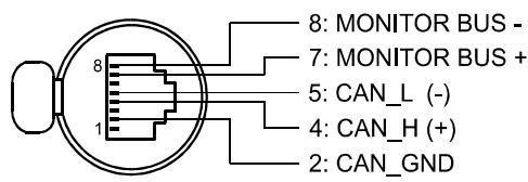
Illustration 4.7: Pin-assignment of CAN jack
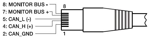
Illustration 4.8: Pin-assignment of CAN plug
Table 4.2: Overview CAN plug
| Pin | Name | Colour | |
| T568A | T568B | ||
| 2 | CAN_GND | Green | Orange |
| 4 | CAN_H (+) | Blue | |
| 5 | CAN_L (-) | Blue striped | |
| 7 | MONITOR BUS + | Brown striped | |
| 8 | MONITOR BUS - | Brown | |
5 STATUS LED
STATUS
The STATUS-LED is for monitoring the communication on the CAN bus. The LED blinks rhythmically every 3 seconds, when the module's address is set to "00", which means that it is disconnected from the CAN bus and software control. The LED blinks rhythmically in intervals of one second, when an address in the range of 01 to 250 has been assigned to the module and there has not yet been any activity on the CAN bus. As soon as communication on the CAN bus is recognized, the LED lights for at least 100 ms, when the power amplifier sends data on the CAN bus.
6 ADDRESS Selector Switch
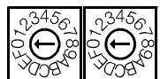
HIGH LOW
CAN ADDRESS
The two address selector switches are for setting the network address of the RCM-26. CAN networks support addresses in the range of 01 to 250 (FA hex). Addressing has to be carried out in the hexadecimal number system. The LOW selector switch sets the lower digit, while HIGH sets the higher digit.
CAUTION:
Each address may exist only once in a system. Otherwise, network conflicts may arise.
Address 0 (00 hex, delivery status) disables remote communication between the RCM-26 and the bus. The module does not appear in the system, even though it is physically connected to the CAN-bus. Switching on the power of an amplifier with an installed RCM-26 that has been assigned address 0 sets all its internal parameters to 0 or bypass and the signal routing to 2-in-2. The power amplifier behaves absolutely linear, i.e. signal processing is deactivated.
Table 4.3: CAN addresses
| HIGH | LOW | Address |
| 0 | 0 | Stand-alone |
| 0 | 1...F | 1...15 |
| 1 | 0...F | 16...31 |
| 2 | 0...F | 32...47 |
| 3 | 0...F | 48...63 |
| 4 | 0...F | 64...79 |
| 5 | 0...F | 80...95 |
| 6 | 0...F | 96...111 |
| 7 | 0...F | 112...127 |
| 8 | 0...F | 128...143 |
| 9 | 0...F | 144...159 |
| A | 0...F | 160...175 |
| B | 0...F | 176...191 |
| C | 0...F | 192...207 |
| D | 0...F | 208...223 |
| E | 0...F | 224...239 |
| F | 0...A | 240...250 |
| F | B...F | reserved |
7 CONTROL PORT
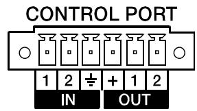
The CONTROL PORT of the RCM-26 provides two control inputs, two control outputs and reference connections for +5V and ground. The control inputs are configurable via IRIS-Net™. They can be used for example for switching between power on / standby modes, switching between preset or to control parameters. The two control contacts IN1 and IN2 are internally connected via pull-up resistors and carry +5V (open). The control inputs can be activated using external switches, pushbuttons or relays to connect them to ground potential (pin 3). The two control outputs OUT1 and OUT2 are open collector outputs, which are highly resistive in the non-active state (off). In active state (on) the outputs are connected to ground. The control outputs are configurable via IRIS-Net™ and are used to signal internal states. LEDs, indicators or relays can be driven directly. The +5V reference connector provides voltage supply for connected components.
CAUTION: The maximally allowable current at the +5V output is 200~mA .
8 RS-232 Interface
The RS-232 interface is for interconnecting the RCM-26 module and multi-media control systems or facility management systems. All parameters can be controlled and queried via RS-232 interface. Communication is realized through the use of ASCII-protocol. Implementation of this protocol is rather simple.
Programming notes and a complete protocol description are included in the IRIS-Net™ documentation. The following illustration shows the pins of the RS-232 interface that the RCM-26 uses. The length of the RS-232 cable that is employed to connect the RCM-26 to another device should not exceed 15 meters.
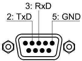
Illustration 4.9: Pin-assignment of RS-232 Interface
The following table shows the factory-fixed settings of the RCM-26's RS-232 interface. The connected device (e.g. a PC with terminal program, multi-media control software) needs to be identically configured for data transfer to work properly.
Table 4.4: Parameter of RS-232 Interface
| Parameter | Value |
| Data bit | 8 |
| Parity bit | - |
| Stop bit | 1 |
| Transfer rate | 19200 bit/s |
CAN Bus Principles
The network topology used by the CAN bus is based on the so-called "bus or line topology", i.e. all participants are connected via a single two-wire cable (Twisted-Pair cable, shielded or unshielded) with the cabling running from one participant on the bus to the next, allowing unlimited communication among all devices. In general, it does not matter if the bus member is a RCM-26, a USB-CAN converter or another device. Thus, the RCM-26 can be connected at any place of the CAN bus. In total, up to 100 devices can be connected to one CAN bus.
The CAN bus has to be terminated with a 120 terminating resistor at both ends. If the termination is missing or an improper resistor value is used, network errors can occur as a signal is reflected on the bus at both bus ends. Because of the superposition of the reflection with the original signal, the original signal is blurred. This may result in the loss of data. In order to prevent or minimize reflections at the bus ends, terminators are used as they "absorb" the energy of the signal.
Since the CAN interfaces of all EVI Audio appliances are galvanically separated from the rest of the circuitry, network cabling also carries a common ground conductor (CAN_GND) ensuring that all CAN-interfaces in the network are connected to a common ground potential.
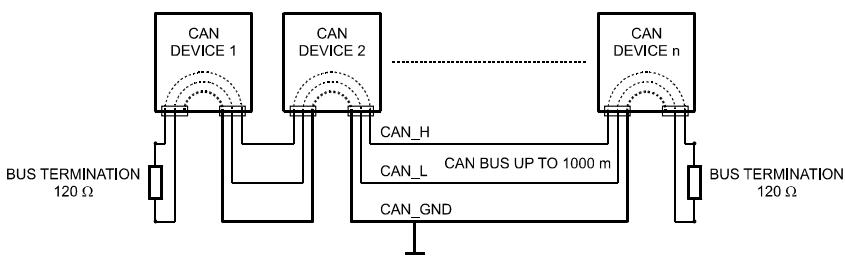
Illustration 4.10: Bus Topology of the CAN bus
By using a CAN bus repeater a connection between two independent and self-contained CAN bus systems can be created. Thus, the following can be achieved:
- Increase of the max. number of members
A maximum of 100 devices can be connected to one CAN bus. This number can be increased up to 250 by connecting several CAN bus systems. This limitation of exactly 250 devices results from the addressing scheme used by the CAN bus. The addressing scheme allows the allocation of a maximum of 250 different CAN device addresses.
- Improvement of signal quality
With CAN bus systems, whose bus length exceeds 1000 meters, a CAN bus repeater should be used. The CAN bus repeater accomplishes a signal processing and a reinforcement of the bus signals. The internal running time of the repeaters of approx. 150 ns corresponds to an extension of the bus over approx. 45 meters.
Creation of alternative network topologies
By using one or several repeaters, not only the above-mentioned bus topology, but the creation of other network topologies are also possible.
System Examples
The following illustrations show examples of the data-bus wiring for different sizes of CAN-bus networks.
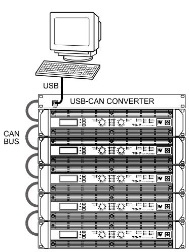
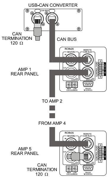
Illustration 4.11: System with 5 power amps (with RCM-26) and 1 USB-CAN Converter. Termination plugs at the USB-CAN Converter and the RCM-26 of amp 5
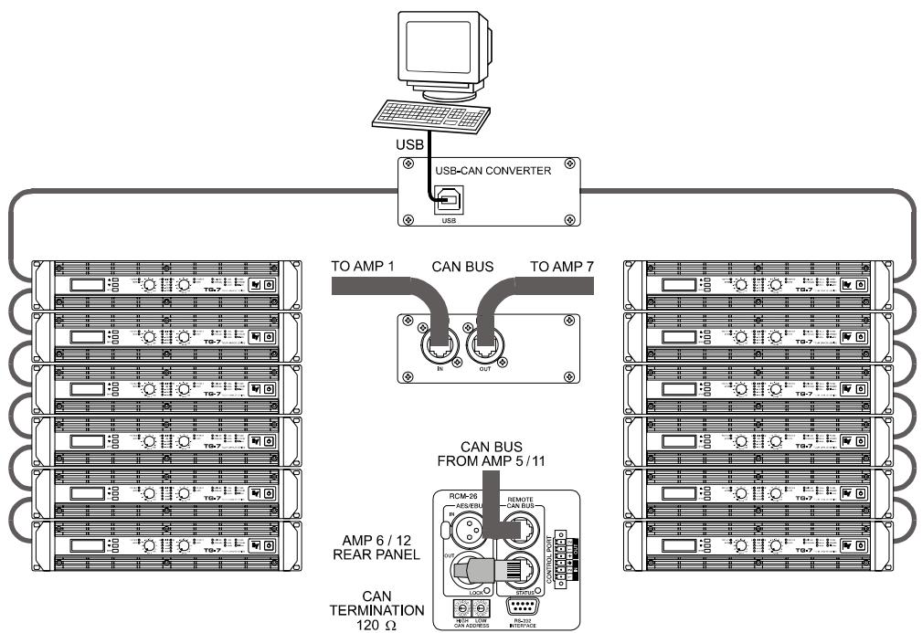
Illustration 4.12: System with 2 amp-racks and 1 USB-CAN Converter. Termination plugs at amp 6 (first unit on the bus) and amp 12 (last unit on the bus)
Performance Specifications
According to the ISO 11898-2 standard, CAN-bus data transfer cabling has to be carried out using Twisted-Pair cables with or without shielding providing a characteristic impedance of 120 . Both ends of a CAN-bus need to be terminated with 120 termination-plugs. The maximum bus-length depends on the actual data transfer rate, the kind of data transfer cable being used, as well as the total number of participants on the bus. The following table shows the most essential requirements for CAN-networks consisting of up to 64 participants.
| Bus Length (in m) | Data Transmission Cable | Termination (in Ω) | Max. Data Transfer Rate | |
| Resistance per Unit Length (in mΩ/m) | Cable Diameter | |||
| 0...40 | < 70 | 0,25...0,34 mm² AWG23, AWG22 | 124 | 1000 kbit/s at 40 m |
| 40...300 | < 60 | 0,34...0,6 mm² AWG22, AWG20 | 127 | 500 kbit/s at 100 m |
| 300...600 | < 40 | 0,5...0,6 mm² AWG 20 | 150...300* | 100 kbit/s at 500 m |
| 600...1000 | < 26 | 0,75...0,8 mm² AWG 18 | 150...300* | 62,5 kbit/s at 1000 m |
- With longer cables and many participants on the CAN-bus, termination resistors with higher impedance than the specified 120 are recommended to reduce the ohmic load of the interface drivers and therefore the voltage drop between the two cable-ends.
The following table is meant for first assessment of necessary cable diameters for different bus lengths and bus-participant numbers.
| Bus Length (in m) | Number of Units on the CAN-Bus | ||
| 32 | 64 | 100 | |
| 100 | 0,25 mm² / AWG24 | 0,34 mm² / AWG22 | 0,34 mm² / AWG22 |
| 250 | 0,34 mm² / AWG22 | 0,5 mm² / AWG20 | 0,5 mm² / AWG20 |
| 500 | 0,75 mm² / AWG18 | 0,75 mm² / AWG18 | 1,0 mm² / AWG17 |
Additionally, the length of branch lines - for participants that are not directly connected to the CAN-bus - is also of importance. For data transfer rates of up to 125 kbit/s, the maximum length of a single stub cable should not exceed 2 meters. For higher bit rates a maximum length of only 0.3 meter is still permissible. The entire length of all branch lines should not exceed 30 meters.
General Note:
- As long as only short distances (up to 10 meters) are concerned, common RJ-45 patch cables with a characteristic impedance of 100 (AWG 24 / AWG 26) can be used for the cabling inside of a rack mounted system.
- The previously outlined guidelines for network cabling are mandatory as far as the rack mounted shelve interconnection or fixed installations are involved.
Declaration of Conformity 145
WARNING: TO REDUCE THE RISK OF FIRE OR ELECTRIC SHOCK, DO NOT EXPOSE THIS APPLIANCE TO RAIN OR MOISTURE.
AVIS: RISQUÉ DE CHOC ELECTRIQUE. NE PAS OUVRIR.
WARNING: CONNECT ONLY TO MAINS SOCKET WITH PROTECTIVE EARTHING CONNECTION.

SAFETY COMPONENT (MUST BE REPLACED BY ORIGINAL PART)
1 Einführung
1.1 Willkommen
BRIDGED MODE: 1x2900 W/8 OHMS
SERIAL:D170379JJMM 00000
TG-7
100-240 V~50-60 Hz
1450 W
OUTPUT POWER
DUAL MODE: 2x2500 W/4 OHMS
BRIDGED MODE: 1x5000 W/8 OHMS
SERIAL: D170378 JJMM 00000
EVENT LOG
Counter POWER UP 8
EVENT LOG
Counter AMP ON 47
EVENTLOG Counter MAINSFAIL 5
EVENTLOG ShowEventHistory
True RMS Mains Voltage and Current Measurement
Output Short Circuit Detection
Monitoring Ambient Temperature
Declaration of Conformity 145
IMPORTANT INFORMATIONS DE SECURITÉ

BRIDGED MODE: 1x2900 W/8 OHMS
SERIAL:D170379JJMM 00000
TG-7
100-240 V~50-60 Hz
1450W
OUTPUT POWER
DUAL MODE: 2 × 2500 ~W / 4 OHMS
BRIDGED MODE:1x5000 W/8 OHMS
SERIAL:D170378 JJMM 00000
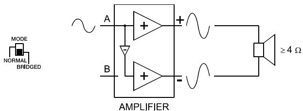
Illustration 2.9: Mode BRIDGED
ATTENTION :

HIGH LOW
CAN ADDRESS
Table 4.3: Adresses CAN
| HIGH | LOW | Addresse |
| 0 | 0 | Indépendant |
| 0 | 1...F | 1...15 |
| 1 | 0...F | 16...31 |
| 2 | 0...F | 32...47 |
| 3 | 0...F | 48...63 |
| 4 | 0...F | 64...79 |
| 5 | 0...F | 80...95 |
| 6 | 0...F | 96...111 |
| 7 | 0...F | 112...127 |
| 8 | 0...F | 128...143 |
| 9 | 0...F | 144...159 |
| A | 0...F | 160...175 |
| B | 0...F | 176...191 |
| C | 0...F | 192...207 |
| D | 0...F | 208...223 |
| E | 0...F | 224...239 |
| F | 0...A | 240...250 |
| F | B...F | réservé |
7 PORT DE CONTROL

Amplifier at rated conditions, both channels driven, 8 load, unless otherwise specified.
| Load Impedance | 2 Ω | 4 Ω | 8 Ω |
| Maximum Midband Output Power THD = 1%, 1 kHz, Dual Channel | 2000 W | 1450 W | 850 W |
| Rated Output Power THD < 0.1%, 20 Hz...20 kHz | - | 1200 W | 600 W |
| Maximum Single Channel Output Power Dynamic-Headroom, IHF-A | 2400 W | 1700 W | 940 W |
| Maximum Single Channel Output Power Continuous, 1 kHz | 2050 W | 1600 W | 900 W |
| Maximum Bridged Output Power THD = 1%, 1 kHz | - | 3800 W | 2900 W |
| Maximum RMS Voltage Swing THD = 1%, 1 kHz | 95 V | ||
| Power Bandwidth THD = 1%, ref. 1 kHz, half power @ 4 Ω | 10 Hz...50 kHz | ||
| Voltage Gain, ref. 1 kHz | 39 dB / 35 dB / 32 dB (switchable) | ||
| Input Sensitivity rated power @ 8 Ω, 1 kHz | 0 dBu / +4 dBu / +7 dBu (switchable) | ||
| THD at rated output power MBW = 80 kHz, 1 kHz | < 0.05% | ||
| IMD-SMPTE 60 Hz, 7 kHz | < 0.05% | ||
| DIM30 3.15 kHz, 15 kHz | < 0.02% | ||
| Maximum Input Level | +22 dBu (9.75 Vrms) | ||
| Crosstalk ref. 1 kHz, at rated output power | <-80 dB | ||
| Frequency Response, ref. 1 kHz | < 10 Hz...30 kHz (±1 dB) | ||
| Input Impedance, active balanced | 20 kΩ | ||
| Damping Factor, 1 kHz | >400 | ||
| Slew Rate | 30 V/μs | ||
| Signal to Noise Ratio Amplifier A-weighted, 32 dB constant gain | 109 dB | ||
| Output Noise, A-weighted, sensitivity 32 dB | <-70 dBu | ||
| Output Stage Topology | Class H Grounded Bridge (2-stage) | ||
| Power Requirements | 100-240 V, 50-60 Hz or 100 V, 50-60 Hz | ||
| Power Consumption 1/8 maximum output power @ 4 Ω | 1000 W | ||
| Protection | Audio Limiters, High Temperature, DC, HF, Short Circuit, Back-EMF, Peak Current Limiters, Inrush Current Limiters, Turn-on Delay, Mains Circuit Breaker Protection, Mains Over/Undervoltage | ||
| Cooling | Front-to-Rear, 5-Stage-Fans | ||
| Ambient Temperatur Limits | +5 °C...+40 °C (40 °F...105 °F) | ||
| Safety Class | I | ||
| Dimensions (W x H x D), mm | 483 x 88.1 x 512 | ||
| Weight | 14.2 kg (31.3 lbs) | ||
Depending on the ambient temperature, the unit might not operate continuously at 2 load in Normal Mode or 4 in Bridged Mode.
TG-7
Amplifier at rated conditions, both channels driven, 8 loads, unless otherwise specified.
| Load Impedance | 2 Ω | 4 Ω | 8 Ω |
| Maximum Midband Output Power THD = 1%, 1 kHz, Dual Channel | 3500 W | 2500 W | 1500 W |
| Rated Output Power THD < 0.1%, 20 Hz...20 kHz | - | 2100 W | 1050 W |
| Maximum Single Channel Output Power Dynamic-Headroom, IHF-A | 4500 W | 3200 W | 1800 W |
| Maximum Single Channel Output Power Continuous, 1 kHz | 4100 W | 2700 W | 1600 W |
| Maximum Bridged Output Power THD = 1%, 1 kHz | - | 7000 W | 5000 W |
| Maximum RMS Voltage Swing THD = 1%, 1 kHz | 125 V | ||
| Power Bandwidth THD = 1%, ref. 1 kHz, half power @ 4 Ω | 10 Hz...50 kHz | ||
| Voltage Gain, ref. 1 kHz | 41 dB / 35 dB / 32 dB (switchable) | ||
| Input Sensitivity rated power @ 8 Ω, 1 kHz | 0 dBu / +6 dBu / +9 dBu (switchable) | ||
| THD at rated output power MBW = 80 kHz, 1 kHz | < 0.05% | ||
| IMD-SMPTE 60 Hz, 7 kHz | < 0.05% | ||
| DIM30 3.15 kHz, 15 kHz | < 0.02% | ||
| Maximum Input Level | +22 dBu (9.75 Vrms) | ||
| Crosstalk ref. 1 kHz, at rated output power | <-80 dB | ||
| Frequency Response ref. 1 kHz | < 10 Hz...30 kHz (±1 dB) | ||
| Input Impedance active balanced | 20 kΩ | ||
| Damping Factor 1 kHz | >400 | ||
| Slew Rate | 35 V/μs | ||
| Signal to Noise Ratio Amplifier A-weighted, 32 dB constant gain | 111 dB | ||
| Output Noise, A-weighted | <-70 dBu | ||
| Output Stage Topology | Class H Grounded Bridge (3-stage) | ||
| Power Requirements | 100-240 V, 50-60 Hz / 100 V, 50-60 Hz | ||
| Power Consumption 1/8 maximum output power @ 4 Ω | 1450 W | ||
| Protection | Audio Limiters, High Temperature, DC, HF, Short Circuit, Back-EMF, Peak Current Limiters, Inrush Current Limiters, Turn-on Delay, Mains Circuit Breaker Protection, Mains Over/Undervoltage Protection | ||
| Cooling | Front-to-Rear, 5-Stage-Fans | ||
| Ambient Temperatur Limits | +5 °C...+40 °C (40 °F...105 °F) | ||
| Safety Class | I | ||
| Dimensions (W x H x D), mm | 483 x 88.1 x 512 | ||
| Weight | 14.5 kg (32.0 lbs) | ||
Depending on the ambient temperature, the unit might not operate continuously at 2 load in Normal Mode or 4 in Bridged Mode.
RCM-26
| NETWORK AND GENERAL FEATURES | |
| Remote Control and Software | IRIS-NetTM, Multiple PCs possible, MS Windows 98, 2000, XP |
| Maximum Configuration | 250 Amplifiers in total, 100 Amplifiers per CAN bus, 2000 meter cable run |
| Supervised Amplifier Parameters | Operation mode, temperature, output voltage and current, impedance of connected speakers, protection mode status, mains voltage and current, power consumption, pilot tone detection |
| Network Supervision | CAN bus failures, defective or missing amplifiers, bandwidth, failure protocol and messaging |
| Audio Monitoring | All input and output signals |
| AUDIO SPECIFICATIONS | |
| Analog Audio Input | 2 audio inputs on internal slot connector, pre-/post fader selectable |
| Input Level (nominal) | +6 dBu / 1.55 V |
| Input Level (max. before clip) | +21 dBu / 8.7 V |
| A/D Conversion | 24 Bit linear, Sigma-Delta, 128 times over-sampling |
| Digital Audio Input | AES3 (AES/EBU) format, XLR In/Thru connectors |
| Input Sample Rates | 32 kHz...192 kHz, internal Sample-Rate-Converter |
| Audio Output | 2 audio outputs on internal slot connector |
| Output Level (nominal) | +6 dBu / 1.55 V |
| Output Level (max. before clip) | +21 dBu / 8.7 V |
| D/A Conversion | 24 Bit, Sigma-Delta, 128 times over-sampling |
| Monitor Outputs | 2 x RJ-45 (REMOTE), electronically symmetric (Pins 7/8) |
| Frequency Response | 20 Hz...40 kHz (-1.0 dB) |
| Signal to Noise Ratio (A-weighted) | ADC: 120 dB typicalDAC: 118 dB typicalAES3: 128 dB typicalAnalog In to Analog Out: 116 dB typical |
| THD+N | < 0.005% |
| Signal Delay | 1.031 ms @ 96 kHz |
| Crosstalk | < -110 dB @ 1 kHz |
| SIGNAL PROCESSING | |
| Sample Rate | 96 kHz (48 kHz optional) |
| Data Format | 24 Bit linear A/D and D/A conversion, 48 Bit processing |
| Signal Processing | 2 DSPs (150 MHz, 300 MIPS) |
| Master EQ (Input) | 6 filters per channel, selectable as PEQ, Lo-Shelf, Hi-Shelf, Hi-Pass and Lo-Pass |
| Master Delay (Input) | 2...2000 ms per channel (units: μs, ms, m, inches, feet, samples) |
| Channel EQ (Output) | 6 filters per channel, selectable as PEQ, Lo-Shelf, Hi-Shelf, Hi-Pass, Lo-Pass and All-Pass |
| X-Over | Hi-Pass and Lo-Pass per channel, 6/12/18/24 dB Bessel/Butterworth, 12/24 dB Linkwitz-Riley |
| FIR Filters | Zero-Latency Processing, Linear Phase X-Over |
| Dynamics | Compressor and Limiter per channel |
| Other Functions | Input Routing, Level, Mute, Polarity, Sine and Noise Generator, Pilot Generator, Level Meters |
| Protection | Digital Speaker Protection |
| INTERFACES | |
| CAN | 10...500 kbaud, 2 x RJ-45 (IRIS-NetTM Control) |
| RS-232 | 9pin DSUB female (Multi-Media Control) |
| GPIO Control Port | 1 x 6-pole Euro block2 Control Inputs2 Control Outputs2 Reference Outputs (+5 V, 200 mA / GND) |
| RCM-26 GENERAL SPECIFICATIONS | |
| Supply Voltage / Current | +5 V DC / 650 mA +15 V DC / 250 mA -15 V DC/ 120 mA |
| Power Consumption | 9 W |
| Operating Temperatur Range | 0 °C...40 °C |
| Dimensions (W x H x D), mm | 84.7 x 80.4 x 230.3 |
| Weight | 240 g |
| ACCESSORIES | |
| 6-pole Euro block connector | For GPIO Control Port |
Declaration of Conformity
DECLARATION OF CONFORMITY
Wir/We EVIAUDIOGmbH
Hirschberger Ring 45
D-94315 Straubing
Germany
being solely responsible herfore declare that the product:
which is the subject of this declaration complies with the following standard(s) or normative document(s)
Technical Regulations: EN 55103-2: 1996
EN 61000-3-2: 2000 + A2: 2005
EN 61000-3-3: 1995 + A1: 2001
EN 60065:2003/IEC 60065 7th. Edition
Place and date of issue
G. Krauss
Legally binding signature
of the PERSON IN CHARGE
Telex Communications Inc. 12000 Portland Ave South, Burnsville, MN 55337, USA
USA:
Phone:1-800-392-3497
Fax: 1-800-955-6831
Canada:
Phone: 1-866-505-5551
Latin America:
Fax:1-866-336-8467
Phone: 1-952-887-5532
Fax: 1-952-736-4212
Europe, Africa & Middle-East
Germany:
EVI Audio GmbH
Hirschberger Ring 45
D-94315 Straubing
Germany
Phone: +49 9421 706-0
Fax: +49 9421 706-265
France:
EVI Audio France S.A.
Parc de Courcerin
Allée Lech Walesa
F 77185 Lognes
France
Phone: +33 1-6480-0090
Fax: +33 1-6006-5103
UK:
Shuttlesound
4 The Willows Centre
Willow Lane
Mitcham
Surrey CR4 4NX
UK
Phone: +44 208 646 7114
Fax: +44 208 254 5666
Asia & Pacific Rim
Japan:
EVI Audio Japan Ltd.
5-3-8 Funabashi
Setagaya-Ku
Tokyo
Japan 156-0055
Phone: +81 3-5316-5020
Fax: +81 3-5316-5031
China:
Telex EVI Audio (Shanghai) Ltd.
Room 3105-3109
No.1 Building
No. 218, Tian Mu West Road
Shanghai
China
PC:200070
Phone: +86 21-6317-2155
Fax: +86 21-6317-3023
Hong Kong:
Telex EVI Audio (HK) Ltd.
Unit 5, 1/F,
Topsail Plaza 11 On Shum Street Shek Mun
Shatin
HK
Phone: +852 2351-3628
Fax: +852 2351-3329
Singapore:
Telex Communications (SEA) Pte. Ltd.
38C Jalan Pemimpin
Singapore 577180
Phone: (65) 6319 0621
Fax: (65) 6319 0620
- Installation 7
- Operation 19
- Options 35
- INHALT
- Einführung 50
- IMPORTANT SAFETY INSTRUCTIONS
- IMPORTANT SERVICE INSTRUCTIONS
- Introduction
- Welcome
- Unpacking and Inspection
- Scope of Delivery and Warranty
- Features and Description
- Responsibility of the User
- Speaker System Damage
- Dangers at the Loudspeaker/Power Outputs
- HF-Interference
- Installation
- Controls, Indicators and Connections
- Rear View
- Factory Settings
- Operating Voltage
- CAUTION:
- TG-5
- TG-7
- Mains Operation & Resulting Temperature
- Mains Switch
- Mounting
- Front Mounting of the Power Amplifier
- Rear Mounting
- Ventilation
- Groundlift
- Indication of the Operation Mode
- Selecting the Mode Of Operation
- ROUTING
- DUAL
- PARALLEL
- MODE
- NORMAL
- BRIDGED
- SENSITIVITY/GAIN
- NOTE:
- Audio Cabling
- Input (XLR / Phoenix)
- Output (Speakon-type Connectors / Terminals) in Normal Mode
- Typical Speaker System Cabling
- Bi-Amp Cabling
- Output (Speakon-type Connectors / Terminals) in Bridged Mode
- Operation
- Volume Control
- Graphical LC display
- Power Amplifier Menu Navigation
- Structure of the CONFIG menu
- Structure of the CONFIG/EVENT LOG menu
- Structure of the CONFIG/DISPLAY SETUP menu
- Structure of the CONFIG/SERVICE menu
- Structure of the MODULE CONFIG menu
- Indications
- PROTECT
- MUTE
- -30dB...LIMIT
- POWER
- STANDBY
- IRIS-Net
- Fan Cooling
- Protections
- True RMS Mains Voltage and Current Measurement
- Mains Circuit Breaker Protection
- Output Short Circuit Detection
- Advanced Thermal Protection
- Monitoring Ambient Temperature
- HF-Limiter
- Options
- RCM-26
- System Description
- Installation Notes
- Installation
- Conversion from Pre Fader Mode to Post Fader Mode
- IRIS-NetTM
- Controls and Connections
- AES/EBU-IN
- AES/EBU-OUT
- LOCK-LED
- REMOTE CAN BUS Connection
- STATUS LED
- ADDRESS Selector Switch
- CONTROL PORT
- CAUTION: The maximally allowable current at the +5V output is 200~mA .
- RS-232 Interface
- CAN Bus Principles
- System Examples
- Performance Specifications
- General Note:
- Declaration of Conformity 145
- Einführung
- Willkommen
- IMPORTANT INFORMATIONS DE SECURITÉ
- ATTENTION :
- PORT DE CONTROL
- RCM-26
- Declaration of Conformity
- Europe, Africa & Middle-East
- Asia & Pacific Rim
Brand : ELECTRO-VOICE
Model : TG-5
Category : Microphone