PLATINUM 7200 IR M7 - Server MAXDATA - Free user manual and instructions
Find the device manual for free PLATINUM 7200 IR M7 MAXDATA in PDF.


User questions about PLATINUM 7200 IR M7 MAXDATA
0 question about this device. Answer the ones you know or ask your own.
Ask a new question about this device
Download the instructions for your Server in PDF format for free! Find your manual PLATINUM 7200 IR M7 - MAXDATA and take your electronic device back in hand. On this page are published all the documents necessary for the use of your device. PLATINUM 7200 IR M7 by MAXDATA.
USER MANUAL PLATINUM 7200 IR M7 MAXDATA
SafetyWarnings and Cautions 7
Intended Application Uses 7
GeneralWarnings 8
Place Battery Marking 8
Site Selection 9
Equipment Handling Practices 9
Power CordWarnings 10
System AccessWarnings 10
Rack MountWarnings 11
Electrostatic Discharge (ESD) 11
Other Hazards 11
Battery Replacement 11
Cooling and Airflow 11
Laser Peripherals or Devices 12
2 Platform Description 13
Platform Features 14
Platform Front 15
Standard Control Panel 16
Platform Rear 18
Processors 19
System Memory 19
Available Memory Configurations 20
Power Subsystem 21
Power Supply Modules 21
Cooling Subsystem 23
Hot-swap PCI Slots 24
Peripherals 25
Hot-Swap Hard Drive 25
Removable Media Drive Bay Support 25
5 1/4-inch Half-height Drive Bay 25
System Board Set 26
Main Board 26
Video Support 29
Ethernet Support 29
Memory Board 30
I/O Riser Board (optional) 31
SAS Riser Board (optional) 32
3 Starting Up and Shutting Down the Server 33
Powering On the Server 33
Shutting Down the Server 33
4 Server Platform Utilities 35
BIOS Setup Utility 35
BIOS Setup Utility Page Layout 35
Keyboard Commands 36
Console Redirect 37
Serial Configuration Settings 37
Keystroke Mappings 38
Setup Alias Keys 38
Limitations 38
Interface to Server Management 38
Sample Setup for Console Redirection 38
Extensible Firmware Interface (EFI) Shell 39
5 User Serviceable Platform Components 43
Tools and Supplies Needed 43
Removing and Installing the Top Cover. 43
Removing the Top Cover. 44
Installing the Top Cover. 44
Hot-swapping a Front System Fan 45
Hot-swapping a Rear System Fan 45
Hot-swapping Hard Disk Drives 47
Determining Drive Status 47
Removing a Hard Disk Drive 48
Mounting a Hard Disk Drive in a Carrier 48
Installing a Hard Disk Drive Assembly. 48
Hot-swapping Power Supplies 49
Removing a Power Supply 49
Installing a Power Supply 49
Installing and Removing PCI Cards 50
Removing Hot-plug PCI Card with Operating System Hot-Plug Interface 50
Removing Hot-plug PCI Card with Hardware Hot-Plug Interface 51
Installing a Hotplug PCI Add-in Card. 52
Removing a Non-Hot-Plug PCI Card 53
Installing a Non-Hot-Plug PCI Card 53
Installing and Removing Memory Boards 54
Removing a Memory Board 54
Installing a Memory Board 55
Installing and Removing DIMMs 55
Memory Population Rules 55
Installing DIMMs 57
Removing DIMMs 58
6 Replacing the CMOS Battery 59
7 Regulatory and Integration Information 61
Product Regulatory Compliance 61
Product Safety Compliance 61
Product RoHS Compliance 61
Product EMC Compliance 61
Product Regulatory Compliance Markings 61
Electromagnetic Compatibility Notices 61
Europe (CE Declaration of Conformity) 61
Appendix A: POST Codes 63
POST Progress Codes and Messages 64
POST Error Messages and Handling 67
POST Error Beep Codes 78
Figures
- PLATINUM 7200 IR Server Front View 13
- Front Components 15
- Front Panel Controls and Indicators 16
- Rear Platform Features 18
- Memory Boards. 19
- Power Supply Indicators 22
- Rear Fan Locations 23
- Hard Drive Carrier 25
- Main Board Component Locations 27
- Main Board Jumpers 28
- Memory Board LEDs and Connectors 30
- I/O Riser Board Connectors 31
- SAS Riser Connectors 32
- Removing the Top Cover 44
- System Fan Location and Removal 45
- Removing a Rear System Fan 46
- Hard Disk Drive Carrier 47
- Attaching the Hard Drive to the Carrier 48
- PCI Slot Attention Button 51
- Opening Memory Board Latches 54
- Removing a Memory Board 54
- Minimum Memory Population 55
- Memory Board A and B Population 56
- Memory Board A, B, C, D Population 56
- Remove Memory Board DIMM Cover 57
- Install DIMMs 58
- Removing the Battery 60
Tables
- SafetyWarnings and Cautions 7
- Chassis Feature Summary 14
- Front Components 15
- Front Panel Controls and Indicators 16
- Rear Platform Features 18
- Power Supply Indicators 22
- Power Indicator 24
- Attention Indicator 24
- Hard Disk Drive Carrier 25
- Main Board Component Locations 27
- Hot-Plug Memory Board LEDs and Buttons 30
- BIOS Setup Utility Page Layout 35
- BIOS Setup: Keyboard Commands 36
- EFI Shell Commands 40
- Hard Disk Drive Carrier 47
- Product Certification Markings 61
- Port 80 POST Code LEDs 63
- POST Progress Codes and Messages 64
- POST Error Manager Messages and Handling 68
- Beep Codes 78
1 Safety Information
This document applies to MAXDATA PLATINUM Server Boards, MAXDATA PLATINUM Server Chassis (pedestal and rack-mount) and installed peripherals. To reduce the risk of bodily injury, electrical shock, fire, and equipment damage, read this document and observe all warnings and precautions in this guide before installing or maintaining your MAXDATA PLATINUM server product.
In the event of a conflict between the information in this document and information provided with the product or on the website for a particular product, the product documentation takes precedence.
Your server should be integrated and serviced only by technically qualified persons.
You must adhere to the guidelines in this guide and the assembly instructions in your server manuals to ensure and maintain compliance with existing product certifications and approvals. Use only the described, regulated components specified in this guide. Use of other products/components will void the UL Listing and other regulatory approvals of the product, and may result in noncompliance with product regulations in the region(s) in which the product is sold.
SafetyWarnings and Cautions
To avoid personal injury or property damage, before you begin installing the product, read, observe, and adhere to all of the following safety instructions and information. The following safety symbols may be used throughout the documentation and may be marked on the product and/or the product packaging.
Table 1. SafetyWarnings and Cautions
| ! | Indicates potential hazard if indicated information is ignored |
| Indicates shock hazard that results in serious injury or death if safety instructions are not followed | |
| Indicates hot components and surfaces | |
| Indicates electrostatic discharge cautions | |
| Indicates do not touch fan blades, may result in injury | |
| Indicates to unplug all AC power cord(s) to disconnect AC power |
Intended Application Uses
This product was evaluated as Information Technology Equipment (ITE), which may be installed in offices, schools, computer rooms, and similar commercial type locations. The suitability of this product for other product categories and environments (such as medical, industrial, residential, alarm systems, and test equipment), other than an ITE application, may require further evaluation.
GeneralWarnings
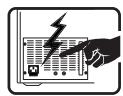
The power supply in this product contains no user-serviceable parts. There may be more than one supply in this product. Refer servicing only to qualified personnel.
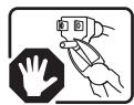
Do not attempt to modify or use the supplied AC power cord if it is not the exact type required. A product with more than one power supply will have a separate AC cord for each supply.
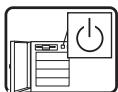
The DC push-button on/off switch on the front panel does not turn off system AC power. To remove power from the system, you must unplug each AC power cord from the wall outlet or power supply.
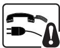
Ensure that the system is disconnected from its power source and from all telecommunication links, networks, and modem lines whenever the chassis cover is to be removed. This may require disconnecting multiple power cords. Do not operate the system with the cover removed.
A microprocessor and heat sink may be hot if the system has been running. Also, there may be sharp pins and edges on some board and chassis parts. Contact should be made with care. Consider wearing protective gloves.

Danger of explosion if the battery is incorrectly replaced. Replace only with the same or equivalent type recommended by the equipment manufacturer. Discard used batteries according to manufacturer's instructions.
Depending on the weight of the product, two people together should lift it.
The system is designed to operate in a typical office environment. Choose a site that is:
- Clean and free of airborne particles (other than normal room dust).
- Well ventilated and away from sources of heat including direct sunlight.
- Away from sources of vibration or physical shock.
- Isolated from strong electromagnetic fields produced by electrical devices.
- In regions that are susceptible to electrical storms, we recommend you plug your system into a surge suppresser and disconnect telecommunication lines to your modem during an electrical storm.
Provided with a properly grounded wall outlet. - Provided with sufficient space to access the power supply cords, because they serve as the product's main power disconnect.
Place Battery Marking
There is insufficient space on this server board to provide instructions for replacing and disposing of the battery. For system safety certification, the following statement or equivalent statement may be required to be placed permanently and legibly on the chassis near the battery.

CAUTION
Risk of explosion if battery is incorrectly replaced.
Replace with only the same or equivalent type recommended by the manufacturer. Dispose of used batteries according to the manufacturer's instructions.
Site Selection
The system is designed to operate in a typical office environment. Choose a site that is:
- Clean, dry, and free of airborne particles (other than normal room dust).
Well-ventilated and away from sources of heat including direct sunlight and radiators. - Away from sources of vibration or physical shock.
- Isolated from strong electromagnetic fields produced by electrical devices.
- In regions that are susceptible to electrical storms, we recommend you plug your system into a surge suppresser and disconnect telecommunication lines to your modem during an electrical storm.
Provided with a properly grounded wall outlet. - Provided with sufficient space to access the power supply cord(s), because they serve as the product's main power disconnect.
Equipment Handling Practices
Reduce the risk of personal injury or equipment damage:
- Conform to local occupational health and safety requirements when moving and lifting equipment.
- Use mechanical assistance or other suitable assistance when moving and lifting equipment.
- To reduce the weight for easier handling, remove any easily detachable components.

CAUTION
The power button, indicated by the stand-by power marking, DOES NOT completely turn off the system AC power, 5 V standby power is active whenever the system is plugged in. To remove power from system, you must unplug the AC power cord from the wall outlet. Your system may use more than one AC power cord. Make sure all AC power cords are unplugged. Make sure the AC power cord(s) is/are unplugged before you open the chassis, or add or remove any non hot-plug components.
Do not attempt to modify or use an AC power cord if it is not the exact type required. A separate AC cord is required for each system power supply.
Some power supplies in MAXDATA PLATINUM Servers use Neutral Pole Fusing. To avoid risk of shock use CAUTION when working with power supplies that use Neutral Pole Fusing.
The power supply in this product contains no user-serviceable parts. Do not open the power supply. Hazardous voltage, current and energy levels are present inside the power supply. Return to manufacturer for servicing.
When replacing a hot-plug power supply, unplug the power cord to the power supply being replaced before removing it from the server.
To avoid risk of electric shock, turn off the server and disconnect the power cord, telecommunications systems, networks, and modems attached to the server before opening it.
Power CordWarnings
If an AC power cord was not provided with your product, purchase one that is approved for use in your country.

CAUTION
To avoid electrical shock or fire, check the power cord(s) that will be used with the product as follows:
- Do not attempt to modify or use the AC power cord(s) if they are not the exact type required to fit into the grounded electrical outlets
-
The power cord(s) must meet the following criteria:
-
The power cord must have an electrical rating that is greater than that of the electrical current rating marked on the product.
-
The power cord must have safety ground pin or contact that is suitable for the electrical outlet.
-
The power supply cord(s) is/are the main disconnect device to AC power. The socket outlet(s) must be near the equipment and readily accessible for disconnection.
- The power supply cord(s) must be plugged into socket-outlet(s) that is /are provided with a suitable earth ground.
System AccessWarnings

CAUTION
To avoid personal injury or property damage, the following safety instructions apply whenever accessing the inside of the product:
- Turn off all peripheral devices connected to this product.
- Turn off the system by pressing the power button to off.
- Disconnect the AC power by unplugging all AC power cords from the system or wall outlet.
- Disconnect all cables and telecommunication lines that are connected to the system.
- Retain all screws or other fasteners when removing access cover(s). Upon completion of accessing inside the product, refasten access cover with original screws or fasteners.
- Do not access the inside of the power supply. There are no serviceable parts in the power supply. Return to manufacturer for servicing.
- Power down the server and disconnect all power cords before adding or replacing any non hotplug component.
- When replacing a hot-plug power supply, unplug the power cord to the power supply being replaced before removing the power supply from the server.

CAUTION
If the server has been running, any installed processor(s) and heat sink(s) may be hot. Unless you are adding or removing a hot-plug component, allow the system to cool before opening the covers. To avoid the possibility of coming into contact with hot component(s) during a hot-plug installation, be careful when removing or installing the hot-plug component(s).

CAUTION
To avoid injury do not contact moving fan blades. If your system is supplied with a guard over the fan, do not operate the system without the fan guard in place.
Rack MountWarnings
The equipment rack must be anchored to an unmovable support to prevent it from tipping when a server or piece of equipment is extended from it. The equipment rack must be installed according to the rack manufacturer's instructions.
Install equipment in the rack from the bottom up, with the heaviest equipment at the bottom of the rack.
Extend only one piece of equipment from the rack at a time.
You are responsible for installing a main power disconnect for the entire rack unit. This main disconnect must be readily accessible, and it must be labeled as controlling power to the entire unit, not just to the server(s).
To avoid risk of potential electric shock, a proper safety ground must be implemented for the rack and each piece of equipment installed in it.
Electrostatic Discharge (ESD)

CAUTION
ESD can damage disk drives, boards, and other parts. We recommend that you perform all procedures at an ESD workstation. If one is not available, provide some ESD protection by wearing an antistatic wrist strap attached to chassis ground - any unpainted metal surface - on your server when handling parts.
Always handle boards carefully. They can be extremely sensitive to ESD. Hold boards only by their edges. After removing a board from its protective wrapper or from the server, place the board component side up on a grounded, static free surface. Use a conductive foam pad if available but not the board wrapper. Do not slide board over any surface
Other Hazards

Battery Replacement
CAUTION
There is the danger of explosion if the battery is incorrectly replaced. When replacing the battery, use only the battery recommended by the equipment manufacturer.
Dispose of batteries according to local ordinances and regulations.
Do not attempt to recharge a battery.
Do not attempt to disassemble, puncture, or otherwise damage a battery.
Cooling and Airflow

CAUTION
Carefully route cables as directed to minimize airflow blockage and cooling problems. For proper cooling and airflow, operate the system only with the chassis covers installed. Operating the system without the covers in place can damage system parts. To install the covers:
- Check first to make sure you have not left loose tools or parts inside the system.
- Check that cables, add-in boards, and other components are properly installed.
- Attach the covers to the chassis according to the product instructions.

Laser Peripherals or Devices
CAUTION
To avoid risk of radiation exposure and/or personal injury:
- Do not open the enclosure of any laser peripheral or device.
- Laser peripherals or devices are not user serviceable.
- Return to manufacturer for servicing.
2 Platform Description
The PLATINUM 7200 IR Server is a compact, high-density, rack-mount system with support for one to four Intel® Xeon™ MP processors and 256 GB of 533 MHz / 667 MHz FBDIMM memory. The platform supports hot plug PCI-Express add-in cards; hot-swap, redundant power supply modules; hot swap, redundant cooling fans; memory with RAS features; and hot-swap hard disk drives. The server platform is shown below.
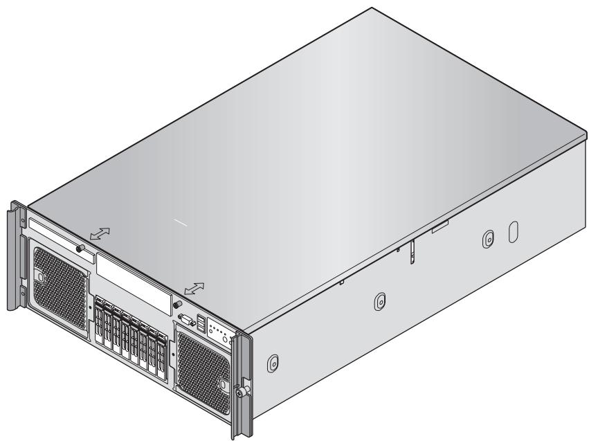
Figure 1. PLATINUM 7200 IR Server Front View
Platform Features
The platform features are outlined in the following table.
Table 2. Chassis Feature Summary
| Feature | Description |
| Dimensions | Height: 6.8 inches (173 mm)Width: 17.6 inches (447 mm)Depth: 27.8 inches (706 mm)Weight of fully configured system: 90 lbs (40 kg) |
| Clearance requirements | • Front clearance: 3 inches (76 mm)• Side clearance: 1 inch (25 mm)• Rear clearance: 6 inches (152 mm) |
| Configuration flexibility/ Scaleability | • Support for one to four processors• Support for at least two generations of processors• Support for up to four 2.5-inch SATA hard drives, or eight 2.5-inch SAS hard drives with optional SAS riser board• Support for up to seven PCI-Express adapters:- Four x8 slots-Three x4 slots• Support for up to 256 GB Fully Buffered DIMM (FBD) Double Data Rate-2 (DDR2) 533 or 667 MHz memory• Support for two integrated gigabit LAN ports, or four integrated gigabit LAN ports with optional I/O riser board |
| Serviceability | • Front access to hot-swap hard disk drives• Front access to hot-swap fans• Rear access to hot-swap power supplies• System power and system status LEDs• System ID buttons and LEDs on front panel and rear of system• Memory status LEDs• Processor failure LEDs• Color-coded parts to identify hot-swap and non-hot-swap serviceable components |
| Availability | • Two hot-plug PCI Express slots• Up to two 1570-watt power supplies in a redundant (1+1) configuration; the second power supply is optional• Dual power cords (1+1) when two power supplies are installed• Up to eight hot-swap system fans in a redundant (7+1) configuration; two rear fans are optional; four rear fans are required for redundancy• Eight hot-swap 2.5-inch SAS hard drives• SAS RAID riser board (optional) with a battery-backed DDR2 DIMM for disk cache |
| Manageability | • Remote management• Emergency Management Port (EMP)• Intelligent Platform Management Interface (IPMI) 1.5 compliant, partial IPMI 2.0 compliance• Wired For Management (WfM) 2.0 compliant• Remote diagnostics support• Optional Intel® Remote Management Module 2 provides remote KVM and media features (requires optional I/O riser) |
| Front control panel | • System power button and LED• System reset button• NMI button• System ID button and LED• System status LED• Hard drive status LED• LAN1 and LAN2 status LEDs• Video connector• Three USB 2.0 ports |
Platform Front
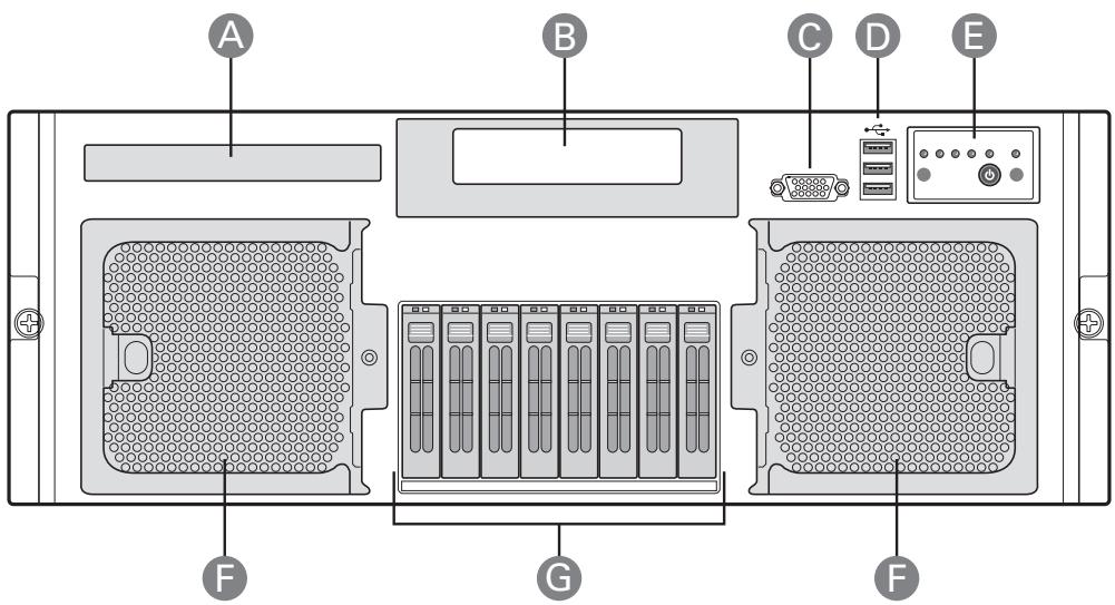
Figure 2. Front Components
Table 3. Front Components
| Item | Description |
| A. | CD-ROM / DVD-ROM drive bay |
| B. | 5 1/4 peripheral bay |
| C. | Video connector |
| D. | USB 2.0 ports |
| E. | Front control panel |
| F. | Hot-swap fan modules (2) |
| G. | Hot-swap disk drives (0-7, from left to right) |
Standard Control Panel
The standard control panel provides a user interface for system management via switches and status LEDs. The control panel also contains the speaker. Figure 3 shows the location of the buttons and status LEDs on the standard control panel.
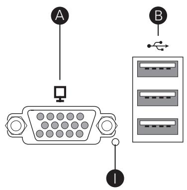
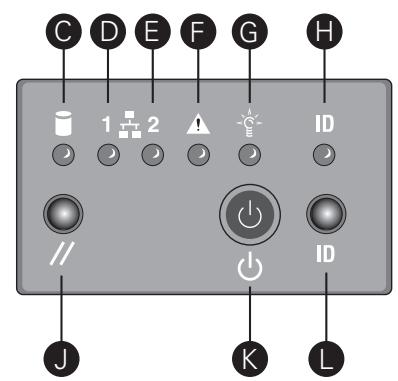
Figure 3. Front Panel Controls and Indicators
Table 4. Front Panel Controls and Indicators
| Item | Feature | Description | ||
| Front Panel Connectors | ||||
| A | Video connector | Video port, standard VGA compatible, 15-pin connector | ||
| B | Three USB connectors | Three USB 2.0 ports, 4-pin connectors | ||
| Front Panel Buttons and LED Indicators | ||||
| C | Hard Drive Activity LED(Green/Amber) | Indicates hard drive activity and fault status. | ||
| LED | State | Description | ||
| Green, On | A hard drive is being initialized. | |||
| Green, Blinking | A hard drive is active. | |||
| Amber, On | Hard drive/slot failure. | |||
| Amber, Slow Blinking (~1 Hz) | A predictive hard drive/slot failure or rebuild in process. | |||
| Amber, Fast Blinking (~2.5 Hz) | Hard drive rebuild interrupted or rebuild on empty slot. | |||
| D,E | LAN1, LAN2 Status LEDs(Green) | Indicates LAN activity status | ||
| LED | State | Description | ||
| Off | Idle | |||
| On | Inactive | No Access | ||
| Blinking | Active | Access | ||
| F | System Status/Fault LED(Green/Amber) | Indicates system status. | ||
| LED | State | Description | ||
| Off | Not ready | AC Power Off,POST error | ||
| Green, On | Ready | System bootedand ready | ||
| Green, Blinking | Degraded | CPU or DIMMdisabled | ||
| Amber, On | Critical Alarm | Critical PowerSupply, Blower,Voltage, ortemperaturefailure | ||
| Amber, Blinking | Non-CriticalAlarm | Redundant PowerSupply or Blowerfailure. Non-Critical Blower,Voltage, andTemperaturefailure. | ||
| G | System Power LED(Green) | Indicates system power status. | ||
| LED | State | ACPI | ||
| Off | Power off | No | ||
| On | Power on | No | ||
| Off | S4/S5 | Yes | ||
| Blinking | S1 | Yes | ||
| On | S0 | Yes | ||
| H | System ID LED (Blue) | Identifies the system via server management or locally. | ||
| I | NMI button | Asserts NMI. | ||
| J | System Reset button | Press to reset the system. | ||
| K | System Power button | Press to turn the system power on or off. | ||
| L | System ID button | Press to turn the System ID LED on or off. | ||
Platform Rear
This diagram shows the system with the optional I/O panel installed.
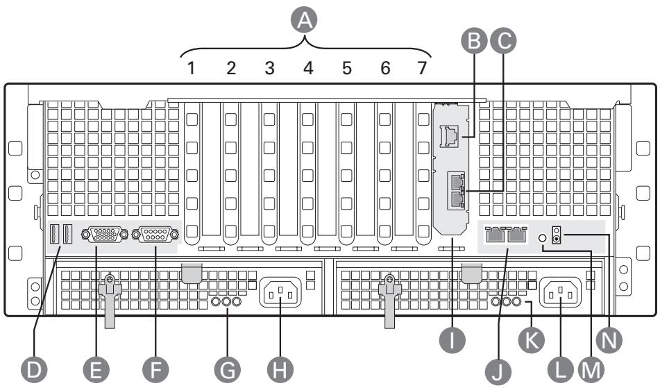
Figure 4. Rear Platform Features
Table 5. Rear Platform Features
| Item | Description | |
| A | PCI Slots | |
| Slot 1 | PCI Express x8, hot-plug | |
| Slot 2 | PCI Express x8, hot-plug | |
| Slot 3 | PCI Express x8, not hot-plug | |
| Slot 4 | PCI Express x8, not hot-plug | |
| Slot 5 | PCI Express x4, not hot-plug | |
| Slot 6 | PCI Express x4, not hot-plug | |
| Slot 7 | PCI Express x4, not hot-plug | |
| B | Intel® Remote Management Module 2 (RMM2) NIC | |
| C | I/O riser Ethernet ports (two) | |
| D | USB ports (two) | |
| E | Standard VGA-compatible video port with 15-pin connector | |
| F | Serial port B connector | |
| G | Power supply LEDs | |
| Power Supply LED | Power Supply Status | |
| Left: Power good (green) | Power supply is on | |
| Center: Fault (amber) | Power supply failure | |
| Right: AC OK (green) | Power supply is connected to AC | |
| H | AC input power connector | |
| I | I/O riser card (optional) | |
| J | LAN 1 (left), LAN 2 (right) RJ45 Ethernet connectors | |
| LAN Port LED | LAN Status | |
| Status LED (green) | Off: No Ethernet connected On: Ethernet link detected Blink: Ethernet link active | |
| Speed LED (green / amber) | Off: 10 Mbps Green: 100 Mbps Amber: 1000 Mbps | |
| K | Power supply LEDs | |
| Power Supply LED | Power Supply Status | |
| Left: Power good (green) | Power supply is on | |
| Center: Fault (amber) | Power supply failure | |
| Right: AC OK (green) | Power supply is connected to AC | |
| L | AC input power connector | |
| M | System ID button | |
| N | Blue system ID LED to identify the system from among many systems | |
Processors
The PLATINUM 7200 IR Server supports from one to four 64-bit Intel® Xeon™ processors MP (7x00 sequence).
System Memory
The memory boards connect to the main board through x16 PCI Express connectors. One to four memory boards can be installed, two on each side of the system. Memory board baffles are not needed for empty memory board slots, but DIMM blanks are required for each socket on each memory board in which a DIMM is not installed.
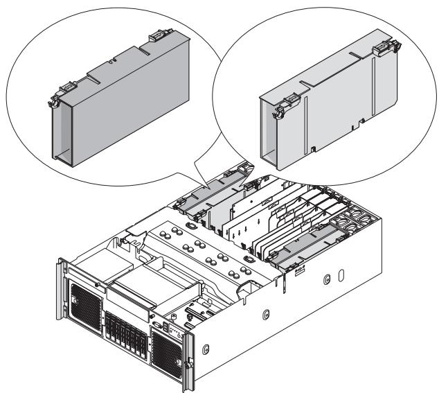
Figure 5. Memory Boards
Each memory board has these features:
Supports up to eight FBD Generation-1 DIMMs
Supports FBD speeds of 533MT/s (4-4-4, 5-5-5 latencies) and 667MT/s (5-5-5 latency)
Supports FBDIMM configurations of x8, x4, single, dual-rank DDR2 DRAMs
Supports DDR2 DRAM technologies of 512 Mbit, 1 Gbit, and 2 Gbit
Supports Closed Loop Thermal Throttling with FBDIMM AMB temperature sensors
- LED fault indicators for each DIMM
One field replaceable unit (FRU) EEPROM
Supports memory mirroring and memory sparing
See "Memory Board" for additional information.
Available Memory Configurations
The BIOS configures the system memory into the best possible configuration after comparing the current FBDIMM population with the desired memory configuration selected by the user in BIOS Setup. Possible configurations are:
- Dual-channel Mode (Maximum Performance Mode): The default setting providing the highest system performance and increased FBD bandwidth. This requires each lock-stepped pair of FBDIMMs on a branch to be identical. A lock-stepped FBDIMM pair is defined as the FBDIMMs installed in identically numbered FBDIMM sockets on both memory riser boards (channels) on a given Memory Branch.
- Single-channel Mode: A failsafe mode when the installed memory configuration is incompatible with dual-channel operation. In single-channel mode, only Branch 0, Channel 0 is operational with all other FBDIMMs disabled automatically.
-
DIMM Sparing Mode: Only supported in a lock-stepped (dual-channel) configuration. DIMM Sparing is the use of a lock-stepped FBDIMM rank on a memory branch to provide a backup in case any other lock-stepped FBDIMM rank on the same branch exceeds a user-selectable Memory ECC Correctable Error threshold in a fixed time period. This failure prediction mechanism allows the system to automatically:
-
Copy the contents of a failing FBDIMM rank to a backup or spare FBDIMM rank
- Disable the failing FBDIMM rank
These actions are completed before the FBDIMM rank begins to generate more serious memory ECC uncorrectable errors that would bring down the system by corrupting memory.
- Memory Mirroring Mode: Memory Mirroring is a high availability mode providing a redundant image of the system memory. This image allows the system to continue operating if memory ECC uncorrectable errors would otherwise bring down the system in another memory configuration.
Power Subsystem
The power subsystem consists of the following:
- Power supply modules
The Power Distribution Board
The power subsystem can be configured with two power supply modules installed for 1 + 1 redundancy at 220 VAC.
Power Supply Modules
The output rating of the power supply is 1570 W when operated between 180 VAC and 264 VAC. It is a current-sharing power supply with auto-ranging input. The power supply is approximately 7.75 inches wide by 14.5 inches deep by 1.47 inches high. The power supply modules have universal AC input with Power Factor Correction (PFC) Distributed Power Supplies (DPS). The AC input receptacle is an IEC-320 C14.
The power supply has two DC outputs: 12 V and 3.3 VSB. The 12 V main power is distributed through the server and is converted locally at the point-of-load using embedded VRM converters. The power supply is capable of power-safe monitoring.
In an N + 1 configuration, the 12 VDC outputs have active (forced) current sharing. The two externally enabled outputs have the following maximum ratings:
+12 VDC: 121 A
+3.3 VDCSB: 5 A
Each power supply module requires one power cord to supply AC power to the system. When two power supply modules and two power cords are installed, the system supports (1 + 1) power cord redundancy. This feature allows the system to be powered by two separate AC sources. In the 1 + 1 configuration, the system continues to operate, without interruption, if one of the AC sources fails.
Each power supply module has three status LEDs. These are located next to the input connector, as shown by the following figure.
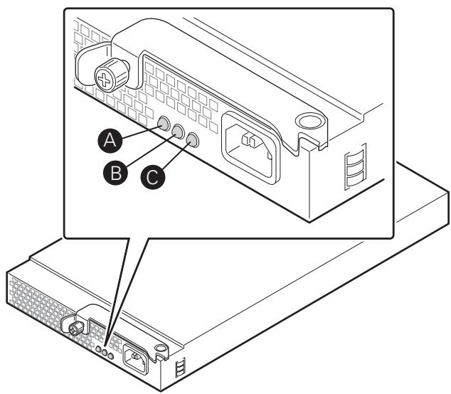
Figure 6. Power Supply Indicators
Table 6. Power Supply Indicators
| Location | Purpose | Description |
| A (left) | Power Good LED (green) | This green LED is driven by internal circuitry and is lit whenever the power is turned on. |
| B (center) | Fault LED (amber) | This amber LED is driven by internal circuitry and is lit when a power rail has failed. The LED is lit even if the power supply is in a latched state. The only time (during a fault) when it is not lit is if the +3.3 VSB is lost. The LED is not lit when the power supply is turned off by powering down the platform. |
| C (right) | AC OK LED (green) | This green LED is driven by internal circuitry and is lit whenever the AC power cord is plugged in to an active AC power source. |
Cooling Subsystem

CAUTION
The chassis top cover must be installed for proper system cooling. Cooling components must be hot-swapped within two minutes. This time period applies only to the time that the cooling component is physically removed, not from the time of failure.
The cooling subsystem consists of hot-swap, redundant (7 + 1) fans. In a redundant configuration, the system supports one fault at a time, either one fan fault or one power supply fault, and it supports hot-swapping one component at a time. If a cooling component fails, the system cooling is maintained and the system continues to operate while the component is hot-swapped.
Each front fan assembly has one status LED. The LED is off when both fans are operating normally. The LED illuminate amber if one or both of the fans fails. Failed front fans can be hot-swapped from the front of the system.
Each rear fan has one status LED. The LED is off when the fan is operating normally and illuminates amber if the fan fails. Failed rear fans can be replaced from the top of the system when the top cover is removed.
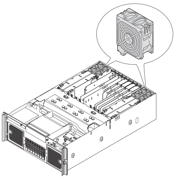
Figure 7. Rear Fan Locations
For proper processor cooling, the processor duct must always be in place. Systems that are configured with fewer than four processors should have processor blanks installed to maintain proper cooling.
Hot-swap PCI Slots
The two hot plug PCI slots have power and attention LEDs. The attention button is used to invoke a hot-plug sequence to remove or add an adapter without having to use the software interface. They are identified by the green arrow on the PCI divider label. The status of the LEDs is shown in Table 7 and Table 8.
Table 7. Power Indicator
| Green Power LED State | Definition |
| Off | Power off: Power has been removed from the slot. A card can be inserted or removed. |
| On | Power on: The slot is powered on. A card cannot be inserted or removed. |
| Blinking | Power transition: The slot is in the process of powering up or down. A card cannot be inserted or removed. |
Table 8. Attention Indicator
| Amber Attention LED State | Definition |
| Off | Normal: Normal operation |
| On | Attention: Power fault or operational problem has occurred with this slot. |
| Blinking | Locate: The slot is being identified at the user’s request. |
NOTE
If you hot-remove a PCI card without following the proper procedure, power will automatically be turned off to the slot.
Peripherals
Hot-Swap Hard Drive
The hot-swap hard drive carrier and SAS backplane board accommodate 2.5-inch SAS or SATA hard drives.
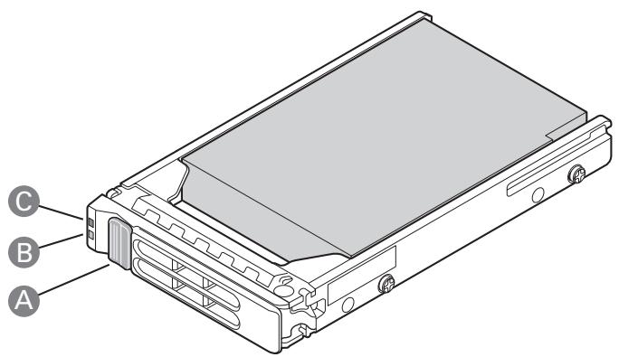
Figure 8. Hard Drive Carrier
Table 9. Hard Disk Drive Carrier
| Item | Description | |
| A | Latch | |
| B | Green LED | |
| Green on | SAS drive is installed and working correctly | |
| Green blink | Hard drive is active | |
| C | Amber LED | |
| Amber on | Hard drive or slot failure | |
| Amber slow blink (~1 Hz) | Predictive hard drive / slot failure or rebuild is in process | |
| Amber fast blink (~2.5 Hz) | Hard drive rebuild interrupted or rebuild on empty slot | |
Removable Media Drive Bay Support
The DVD-ROM/CD-ROM drive is installed in a sheetmetal carrier and is inserted from the front of the chassis. The tape back-up drive is also installed from the front of the chassis. You must power down the platform and remove the top cover to remove or install these devices.
5 1/4-inch Half-height Drive Bay
The system supports one 5 1/4 -inch, half-height device mounted at the front of the system. A USB or SATA tape backup device can be cabled to the internal USB or SATA port located on the main board. Alternatively, a SCSI or SAS tape backup device can be cabled to a PCI Express add-in card (not included).
System Board Set
The board set consists of the following boards:
- Main board
Memory boards
I/O riser board (optional)
SAS riser board (optional) - Front panel board
SAS backplane board
Power distribution board - SATA-to-IDE adapter board
Main Board
The main board contains:
- Chipset north and south bridge components
- Processor sockets
Four memory board connectors - Video components
- Trusted Platform Module
- Seven PCI Express slots
- Back panel I/O connectors
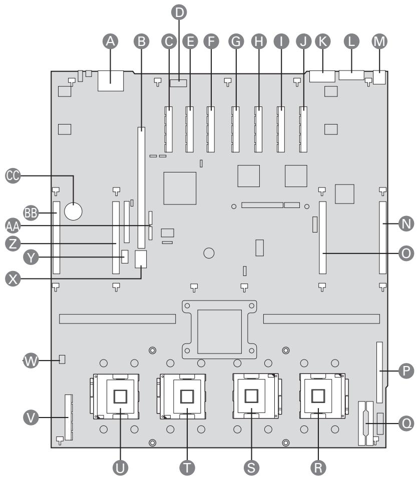
Figure 9. Main Board Component Locations
Table 10. Main Board Component Locations
| Item | Description | Item | Description |
| A | Dual Ethernet ports | P | Front panel connector |
| B | I/O riser slot | Q | Power distribution board connectors (3) |
| C | PCI Express x4 (slot 7) | R | Processor socket 1 |
| D | Serial Port A | S | Processor socket 2 |
| E | PCI Express x4 (slot 6) | T | Processor socket 3 |
| F | PCI Express x4 (slot 5) | U | Processor socket 4 |
| G | PCI Express x8 (slot 4) | V | SAS riser slot |
| H | PCI Express x8 (slot 3) | W | Chassis intrusion |
| I | PCI Express x8 hot-plug (slot 2) | X | 4-port SATA connector |
| J | PCI Express x8 hot-plug (slot 1) | Y | Internal USB port |
| K | Serial port B | Z | Memory board (slot C) |
| L | Video port | AA | Single port SATA connectors |
| M | USB 1 (top), USB 2 (bottom) | BB | Memory board (slot D) |
| N | Memory board (slot A) | CC | Real-time clock battery |
| O | Memory board (slot B) |
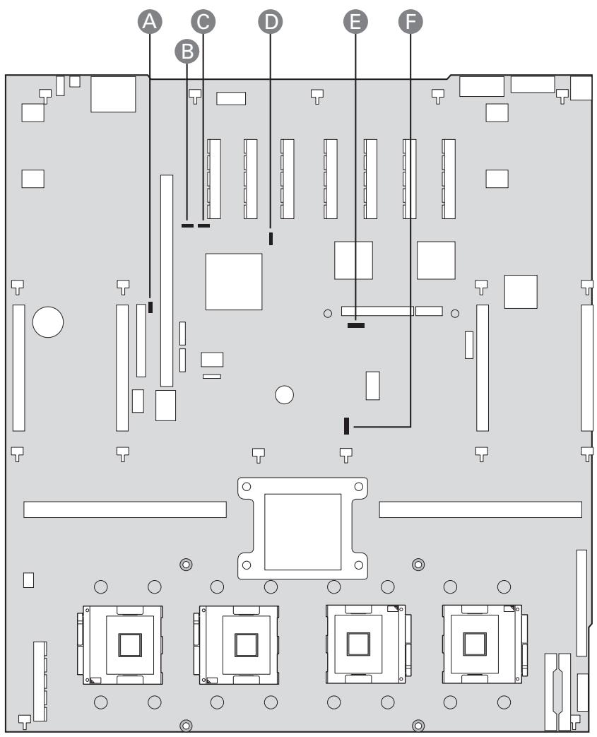
Figure 10. Main Board Jumpers
| Label | Name | Function | Location |
| A | Rolling BIOS | 1 - 2 = Force other bank *2 - 3 = Normal mode | J3D1 |
| B | Password disable or clear | *1 - 2 = Password protect 2 - 3 = Password disabled / cleared | J3C2 |
| C | Clear CMOS / NVRAM | *1 - 2 = Normal 2 - 3 = Forced CMOS / NVRAM clear | J3C3 |
| D | BMC force update | *1 - 2 = Disable BMC force update 2 - 3 = Enable BMC force update | J5C1 |
| E | BMC flash write protect | *1 - 2 = Disable flash write protect 2 - 3 = Enable flash write protect | J6D1 |
| F | Circuit breaker | 1 - 2 = 20A/110V (USA) *2 - 3 = 15A/100V (Japan) | J6F1 |
*Default Jumper Setting
Video Support
The main board uses the ATI RN50 Embedded Video Controller with 32 MB of video RAM. The RN50 provides these features:
2D/3D video accelerator
- Dual DAC for simultaneous port support (front / rear video support)
- Resolutions from VGA up to UXGA (1600 x 1200)
- Digital Video Input/Output (DVI/DVO) interface routed to the Intel® Remote Management Module 2 (RMM) for KVM support up to 165 MHZ
3.3 V 32-bit / 33 MHz PCI host interface
The main board has a standard DB5 video connector.
Ethernet Support
1000/100/10 Ethernet capability is supported by the ESB2 MAC and 82563EB PHY (Physical Layer). The 82563EB PHY outputs two Gbit LAN ports and connects to a 1x2 RJ45 Gbit connector that is accessible at the rear of the system.
Memory Board
One, two, or four memory boards can be installed. Each memory board has eight DIMM sockets that support x4 or x8, single- or dual-rank FBD DDR2 DIMMs. FBD speeds of 533 MT/s (4-4-4, 5-5-5 latencies) and 667 MT/s (5-5-5 latency) are supported. DDR2 DRAM technologies of 512 Mbit, 1 Gbit, and 2 Gbit are supported. The memory boards connect to the main board through x16 PCI Express connectors. The memory boards have LEDs that indicate the status of the memory board power and the status of each DIMM.
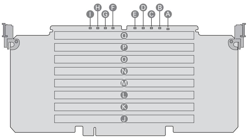
Figure 11. Memory Board LEDs and Connectors
Table 11. Hot-Plug Memory Board LEDs and Buttons
| Item | Description |
| A | Power Good LED (green). The memory board power is good |
| B | DIMM1 Fault LED (amber). DIMM1 had an error and needs to be replaced |
| C | DIMM2 Fault LED (amber). DIMM2 had an error and needs to be replaced |
| D | DIMM3 Fault LED (amber). DIMM3 had an error and needs to be replaced |
| E | DIMM4 Fault LED (amber). DIMM4 had an error and needs to be replaced |
| F | DIMM5 Fault LED (amber). DIMM5 had an error and needs to be replaced |
| G | DIMM6 Fault LED (amber). DIMM6 had an error and needs to be replaced |
| H | DIMM7 Fault LED (amber). DIMM7 had an error and needs to be replaced |
| I | DIMM8 Fault LED (amber). DIMM8 had an error and needs to be replaced |
| J | DIMM1 Socket |
| K | DIMM2 Socket |
| L | DIMM3 Socket |
| M | DIMM4 Socket |
| N | DIMM5 Socket |
| O | DIMM6 Socket |
| P | DIMM7 Socket |
| Q | DIMM8 Socket |
I/O Riser Board (optional)
The I/O riser board is a vertical riser that provides advanced server management with a dedicated maintenance Ethernet port, and additional dual-gigabit Ethernet ports.
The Remote Management Module 2 (RMM2) and RMM2 NIC plug into the I/O riser board to provide an upgrade path to advanced server management capabilities. When the optional RMM2 is installed, the original set of server management features continue to work and additional functionality is available. This functionality seamlessly integrates into the server, with respect to configuration functions and software support.
The RMM2 supports keyboard, mouse, video redirect, and media redirect functionality, which lets the user use the remote system to control the host server.
The Intel 82575EB PCI Express-based Ethernet controller provides advanced networking control and capability with dual-gigabit Ethernet ports. This controller hosts the Intel® I/O Acceleration Technology II (Intel® I/OAT2) capability that provides optimization of the TCP flow. The Intel® I/O riser provides an option to disable Gbit port A and / or port B in the BIOS. Server management traffic over these ports is not supported. For management traffic, use the main board LAN ports.
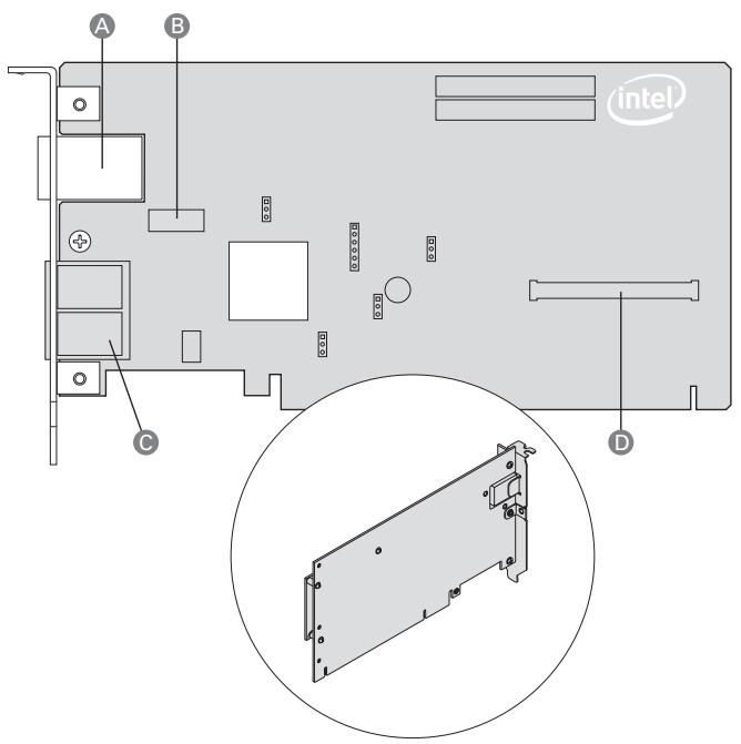
Figure 12. I/O Riser Board Connectors
| Item | Description | Item | Description |
| A | RMM2 NIC | C | Dual gigabit LAN Ethernet ports |
| B | RMM2 NIC connector | D | Remote Management Module 2 connector |
SAS Riser Board (optional)
The SAS riser board works with the SAS backplane board to support eight SAS hard drives. The SAS riser uses a dedicated slot at the front of the system to make cabling to the SAS backplane convenient.
The SAS riser board uses the LSI1078 SAS controller to provide eight SAS channels at up to 3Gb/s. The riser natively supports Integrated RAID levels 0, 1, and 1E.
If the optional RAID Activation Key and DDR2-667 registered DIMM are installed, hardware RAID levels 0, 1, 5, 6, 10, 50, and 60 are enabled. The optional RAID smart battery can be installed to provide DDR2 DIMM refresh support during a power failure.
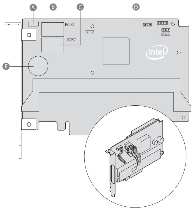
Figure 13. SAS Riser Connectors
| Item | Description | Item | Description |
| A | SES Connector | D | RAID Activation Key |
| B | SAS x4 Port A | E | RAID DIMM Connector |
| C | SAS x4 Port B |
3 Starting Up and Shutting Down the Server
Powering On the Server
Press the power button on the front control panel. The fans start and POST begins.
NOTE
It might take three minutes or longer for video to be displayed, depending on the amount of memory installed.
The server attempts to boot from the first device on the list of available devices in the boot manager. If this device is not available, it will move to the second device. It continues down the list until it reaches the first available device.
Press F2 during POST to enter the BIOS setup utility. This utility also contains a boot manager that allows to select a boot device for immediate boot.
Shutting Down the Server
- Exit the operating system (if applicable)
- Press and hold the power button until the server shuts down.
CAUTION
Powering down the server with the power button does not remove all power from the system. The +3.3V standby power is still available to the system even when it is not running. To remove standby power from the system, unplug all power cords from the system and unplug the power supplies. If you do not unplug the power supplies, standby power may be held up by the integrated capacitors for more than 10 minutes.
4 Server Platform Utilities
BIOS Setup Utility
The BIOS Setup Utility is a text-based utility that allows you to configure the system and view and change device settings and view environmental information for the platform. The BIOS Setup Utility interface consists of several screens, called pages. Each page contains information or links to other pages. The first page in Setup displays links for general categories. These links lead to pages containing specific configuration settings.
The BIOS Setup Utility is functional through console redirection over various terminal emulation standards. This may limit some functionality due to compatibility. For example, colors, some keys or key sequences, and mouse support may be limited.
To enter the BIOS Setup Utility, press <F2> when prompted during POST to access the Systems Options Menu.
BIOS Setup Utility Page Layout
The BIOS Setup Utility page layout is sectioned into functional areas. The following table lists and describes the functional areas and their position on the screen.
Table 12. BIOS Setup Utility Page Layout
| Functional Area | Description |
| Menu Selection Bar | The Menu Selection Bar is located at the top of the screen. It displays the major menu selections available. |
| Setup Item List | The Setup Item List is a set of configurable and informational items. The left column shows the setup item. The right column shows the corresponding option. The option contains an informational value or possible settings for the setup item. |
| Item Specific Help Area | The Item Specific Help area is located on the right side of the screen and contains help text for the highlighted Setup Item. Help information includes the meaning and usage of the item, allowable values, and the affects of the options. |
| Keyboard Command Area | The Keyboard Command Bar is located at the bottom of the screen and displays help for keyboard special keys and navigation keys. The keyboard command bar is context-sensitive. It displays keys relevant to the current page and mode. |
| Status Bar | The Status Bar is on the bottom line of the screen. The status value “NV” indicates you have made changes to Setup that have not been saved. |
Keyboard Commands
The bottom right portion of the Setup screen provides a list of commands that are used to navigate through the BIOS Setup Utility. These commands are context sensitive.
The Keyboard Command Bar supports the following key presses:
Table 13. BIOS Setup: Keyboard Commands
| Key | Option | Description |
| <Enter> | Execute Command | The <Enter> key is used to activate sub-menus when the selected feature is a sub-menu, or to display a pick list if a selected option has a value field, or to select a sub-field for multi-valued features like time and date. If a pick list is displayed, the <Enter> key will select the currently highlighted item, undo the pick list, and return the focus to the parent menu. |
| <Esc> | Exit | The <Esc> key provides a mechanism for backing out of any field. This key will undo the pressing of the <Enter> key. When the <Esc> key is pressed while editing any field or selecting features of a menu, the parent menu is re-entered. When the <Esc> key is pressed in any sub-menu, the parent menu is re-entered. When the <Esc> key is pressed in any major menu, the exit confirmation window is displayed and you are asked whether changes can be discarded. If “No” is selected and the <Enter> key is pressed, or if the <Esc> key is pressed, you are returned to where you were before <Esc> was pressed without affecting any existing any settings. If “Yes” is selected and the <Enter> key is pressed, setup is exited and the BIOS continues with POST. |
| Up Arrow | Select Item | The up arrow is used to select the previous value in a pick list, or the previous option in a menu item's option list. The selected item must then be activated by pressing the <Enter> key. |
| Down arrow | Select Item | The down arrow is used to select the next value in a menu item's option list, or a value field's pick list. The selected item must then be activated by pressing the <Enter> key. |
| Left and Right Arrow | Select Menu | The left and right arrow keys are used to move between the major menu pages. The keys have no affect if a sub-menu or pick list is displayed. |
| <Tab> | Select Field | The <Tab> key is used to move between fields. For example, <Tab> can be used to move from hours to minutes in the time item in the main menu. |
| <> | Change Value | The minus key on the keypad is used to change the value of the current item to the previous value. This key scrolls through the values in the associated pick list without displaying the full list. This key only works for date and time. |
| <++> | Change Value | The plus key on the keypad is used to change the value of the current menu item to the next value. This key scrolls through the values in the associated pick list without displaying the full list. On 106-key Japanese keyboards, the plus key has a different scan code than the plus key on the other keyboard, but will have the same effect. This key only works for date and time. |
| <F9> | Setup Defaults | Pressing <F9> causes the following to appear: Load default configuration now? (Y/N) If the "Y" key is pressed, all Setup fields are set to their default values. If the "N" key is pressed, or if the <Esc> key is pressed, you are returned to where you were before <F9> was pressed without affecting any existing field values |
| <F10> | Save and Exit | Pressing <F10> causes the following message to appear: Save Configuration changes and exit now? (Y/N) If the "Y" key is pressed, all changes are saved and Setup is exited. If the "N" key is pressed, or the <Esc> key is pressed, you are returned to where you were before <F10> was pressed without affecting any existing values. |
Each Setup Utility menu page contains a number of features. Some features are used for informative purposes only, and other features are associated with a value field that you can configure. Depending on the security option chosen and in effect, a menu feature's value may be changeable. If a value cannot be changed, the feature's value field is inaccessible.
Console Redirection
The BIOS supports redirection of both video and keyboard through a serial link (COM port). When console redirection is enabled, local (host server) keyboard input and video output are passed both to the local keyboard and video connections and to the remote console via the serial link. Keyboard inputs from both sources are considered valid and video is displayed to both outputs. With console redirection, the system can be operated without a host keyboard or monitor attached to the system and run entirely via the remote console. Setup and any other text-based utilities can be accessed via console redirection.
Serial Configuration Settings
When redirecting through a modem (as opposed to a null modem cable), the modem needs to be configured with the following:
- Auto-answer (for example, ATS0 = 2 , to answer after two rings).
- Modem reaction to DTR set to return to command state (e.g., AT&D1).
Failure to provide the second item will result in the modem either dropping the link when the server reboots (as in AT&D0) or becoming unresponsive to server baud rate changes (as in AT&D2).
The option for handshaking must be set to RTS/CTS + CD for optimum performance. The CD refers to carrier detect. If EMP is sharing the COM port with serial redirection, the handshaking must be set to Xon/Xoff + CD. In selecting this form of handshaking, the server is prevented from sending video updates to a modem that is not connected to a remote modem. If this is not selected, video update data being sent to the modem inhibits many modems from answering an incoming call. An EMP option utilizing CD should not be used if a modem is not used and the CD is not connected.
Both EMP and console redirection require N, 8, 1 mode (no parity, 8-bit data, 1 stop bit).
The BIOS does not require that the splash logo be turned off for console redirection to function. The BIOS supports multiple consoles, some of which are in graphics mode and some in text mode. The graphics consoles can display the logo while the text consoles receive the redirected text.
The console redirection ends at the beginning of the Legacy OS boot (INT 19h).
Keystroke Mappings
During console redirection, the remote terminal (which may be a dumb terminal or a system with a modem running a communication program) sends keystrokes to the local server. The local server passes video back over this same link. The keystroke mappings follow VT-UTF8 format with the following extensions.
Setup Alias Keys
The and
Limitations
BIOS Console redirection terminates after an EFI-aware operating system calls EFI Boot Service ExitBootServices. The operating system is responsible for continuing the Console Redirection after that point. BIOS console redirection is a text console and any graphical data such as a logo are not redirected.
Interface to Server Management
If BIOS determines that console redirection is enabled, it passes the baud rate through the Intelligent Platform Management Bus (IPMB) to the appropriate management controller.
Sample Setup for Console Redirection
Below is an example of how to configure the console/host and server for console redirection. In this example, the console is running under Microsoft® Windows®. The console and server is directly connected through the serial ports of both systems using a serial null modem cable:
Server Configuration
- Power on the server.
- When prompted, press the <F2> key to enter BIOS Setup.
- The BIOS Setup menu displays the Main menu. Use the arrow keys move to the Server Management menu.
- At the Server Management menu, select Console Redirect.
- Select Serial B Console Redirect.
- Set Console Redirect to "Enabled".
- Set the Bit Rate to "115.2K".
- Set the Flow Control to "RTS/CTS".
- Set the Terminal Type to "PC-ANSI".
- Press the
key. - At the prompt to save changes and exit BIOS Setup, select "Yes" and press the
key. - The server reboots and console redirection is enabled.
- Power down the server and configure the console.
Console Configuration
- Boot the console into the operating system.
- Click the Start button in the task bar.
- Select Programs > Accessories > Communications and click "Hyperterminal".
- At the Connection Description window, enter "guest" for the name and click "Ok".
- At the Connect To window, select the COM port of the console that the Null modem is connected. In this example, it is COM1.
- At the COM1 Properties window, select "115200" in the Bits per second (Baud rate) box to match what was configured on the server.
- Select "Hardware" for the Flow Control to match what was configured in the BIOS Setup (CTS/RTS is the hardware flow control).
- Leave the default settings for the other boxes. Click "Ok" to accept the settings and enter the Hyperterminal screen.
- Power on the server. The console starts displaying the redirection once the video synchronizes on the server.
Extensible Firmware Interface (EFI) Shell
The EFI shell application allows other EFI applications to be launched, EFI device drivers to be loaded, and operating systems to be booted. The combination of the EFI firmware and the EFI Shell provides an environment that can be modified and adapted to many hardware configurations.
The EFI shell provides a set of basic commands to manage files and EFI NVRAM shell and boot variables. A list of these basic commands is in Table 14.
Extensive information is available on the EFI website at http://developer.intel.com/technology/efi.
Table 14. EFI Shell Commands
| Command | Description |
| <drive_name>: | Change drives. For example, entering fs0: and pressing the <Enter> key changes the drive to the LS-240 drive |
| alias [-bdv] [sname] [value] | Sets or gets alias settings |
| attrib [-b] [+/- rhs] [file] | Views or sets file attributes |
| bcfg -? | Configures boot driver and load options in EFI NVRAM |
| botmaint | Launches the Boot Maintenance Manager |
| break | Executes a breakpoint |
| cd [path] | Changes the directory |
| cls [background color] | Clears the screen |
| comp file1 file2 | Compares two files |
| connect [-r] [-c] Handle# %DeviceHandle# DriverHandle# | Binds the EFI driver to a device and starts the driver |
| cp [-r] file [file] ... [dest] | Copies files and directories, [-r] = recursive |
| date [mm/dd/yyyy] | Gets or sets the date |
| dblk device [Lba] [Blocks] | Performs a hex dump of Blklo Devices |
| devices [-b] [-1XXX] | Displays devices |
| devtree [-b] [-d] | Displays device tree |
| dh [-b] [-p prot_id] | [handle] | Dumps handle information |
| disconnect DeviceHandle# [DriverHandle# [ChildHandle#] | Disconnects device from driver |
| dmem {address} [size] [;MMIO] | Displays the contents of memory |
| dmpstore | Dumps the variable store |
| drivers [-b] [-IXXX] | Displays drivers |
| drvcfg [-c] [-IXXX] [-f] [-v] [-s] | Invokes the driver configuration protocol |
| drvdiag [-c] [-IXXX] [-s] [-e] [m] | Invokes the driver diagnostics protocol |
| echo [[-on | -off] | [text] | Echoes text to the standard output device or toggles script echo |
| edit [filename] | Opens the text editor allowing you to create or edit a file |
| eficompress,infile,outfile | Compresses an EFI file |
| Efidecompress,infile,outfile | Decompresses an EFI file |
| endfor | Provides a delimiter for loop constructs (scripts only) |
| endif | Provides a delimiter for IFTHEN constructs (scripts only) |
| for var in <set> | |
| goto label | Makes batch file execution jump to another label |
| guid [-b] [sname] | Dumps known guide ids |
| help [-b] [internal_command] | Displays help information |
| hexedit [[-f]FileName][-d DiskName Offset Size][-m Offset Size]] | Edits in HEX mode |
| if [not] condition then | Provides conditional constructs (scripts only) |
| load driver_name | Loads a driver |
| loadbmp [-c] [-t] [-i[UGA Instance]] file | Displays a bitmap file on the screen |
| loadpcirom romfile | Loads a PCI option ROM |
| Is [-b] [dir] [dir] ... | Obtains directory listings |
| map [-bdvr] [sname[.]] [handle] | Maps sname to device path |
| mem [address] [size] [;MMIO] | Dumps Memory or Memory Mapped IO |
| memmap [-b] | Dumps memory map |
| mkdir dir [dir] | Creates a new directory |
| mm address [Width] [;Type] [n] | Memory Modify: type = Mem, MMIO, IO, PCI, [n] for non interactive mode when inside a .nsh file |
| mode [col row] | Sets or gets the current graphics mode |
| mount BlkDevice [sname[.]] | Mounts a file system on a block device |
| mv [src...] [dst] | Move one or more files/directions to destination |
| pause | Prompts to quit or continue (scripts only) |
| pci [bus_dev] [func] | Displays PCI device information |
| rconnect DeviceHandle# [DriverHandle# [ChildHandle#]] | [-r] | Reconnects one or more drivers from a device |
| reset [reset_string] | Performs a cold reset |
| rm file/dir [file/dir] | Removes files or directories |
| setsize file | Sets size of a new file |
| stall microseconds | Delays for the specified number of microseconds |
| time [hh:mm:ss] | Gets or sets the time |
| type [-a] [-u] [-b] file | Displays the contents of a file |
| ver | Displays version information |
| vol fs [volume_label] | Sets or displays a volume label |
5 User Serviceable Platform Components
Tools and Supplies Needed
- Phillips #2 screwdriver
- Flat head screwdriver
- Antistatic wrist strap (recommended)
Removing and Installing the Top Cover
WARNING
Make sure the rack is anchored securely so it will not tilt forward when the server chassis is extended. A crush hazard exists should the rack tilt forward. This could cause serious injury.
CAUTIONS
For proper cooling and airflow, do not operate the server with the cover removed. Do not leave the chassis cover open or a system fan removed any longer than necessary; system cooling could be reduced.
The server comes with a removable top cover that allows the PCI cards, Memory Boards, and the system fans to be hot-swapped, and the system components to be serviced.
With the exception of the components described in this chapter, all servicing must be done by a qualified service technician.
Removing the Top Cover
To remove the top cover, follow these instructions:
- Observe the safety precautions, warnings, and cautions described in "Safety Information".
- If the chassis is rack-mounted, slide the chassis out far enough to expose the entire top cover.
- Unscrew the two captive screws on the faceplate of the chassis.
- Slide the top cover toward the back of the chassis until the tabs on the cover disengage with the slots in the chassis.
- Lift the cover to remove it.
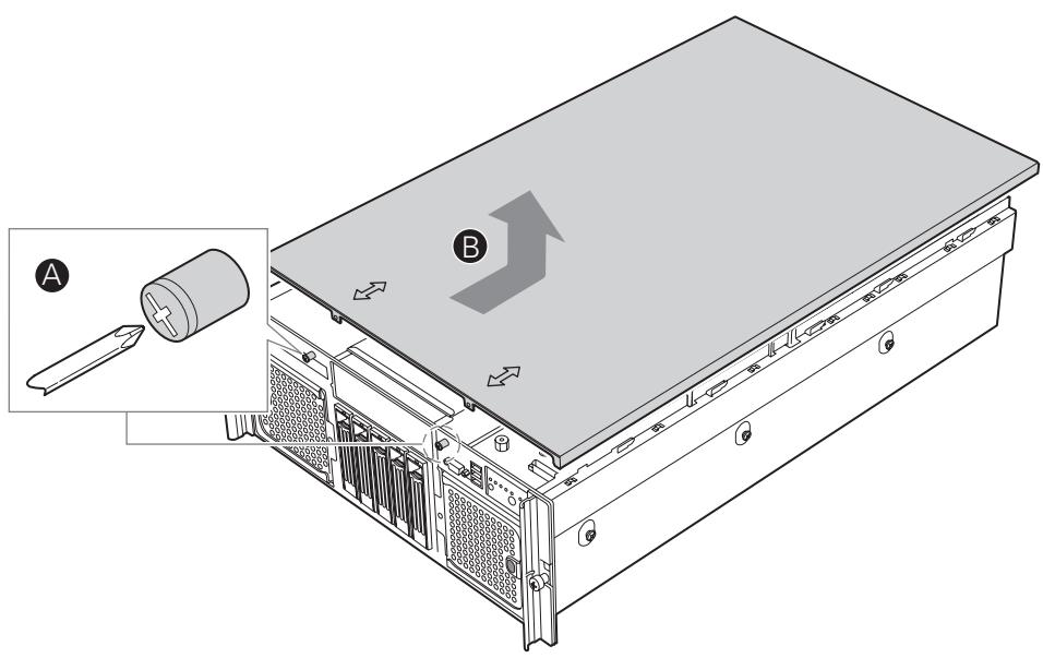
Figure 14. Removing the Top Cover
Installing the Top Cover
To install the top cover, follow these instructions:
- Observe the safety precautions, warnings, and cautions described in "Safety Information"
- Place the top cover on the chassis so the tabs on the cover align with the slots on the chassis.
- Slide the top cover towards the front of the chassis until it is fully closed.
- Tighten the captive screws on the face plate of the chassis.
- Slide the server into the rack.
Hot-swapping a Front System Fan
Two cooling fan assemblies are located at the front of the chassis. Each assembly contains two fans. You cannot replace the individual fans within the assembly, but you can replace each fan assembly. You can replace a failed cooling fan assembly without turning off the power to the server only if the remaining fan in the assembly is fully operational. Each fan assembly uses an amber LED to indicate a failed fan condition. If the amber LED is on, the fan assembly needs to be replaced. The LED remains off during normal operation.
CAUTION
System cooling is reduced during the fan replacement process. Do not leave a system fan removed for longer than two minutes.
Do not touch the fan blades while they are turning.
- Observe the safety, ESD, and other precautions described in "Safety Information."
- Locate the fan assembly you are replacing. If a fan in the assembly has failed, the amber LED will be lit. See letter "A" in Figure 15.
- Press the green button on the front of the fan assembly to release the handle. See letter "B" in the figure.
- Use the handle to pull the fan from the system. See letter "C" in the figure.
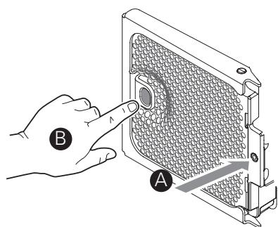
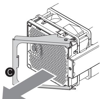
Figure 15. System Fan Location and Removal
- Open the handle on the replacement fan assembly.
- Slide the replacement fan into the fan bay.
- Push the handle closed until it clicks into place.
Hot-swapping a Rear System Fan
Four cooling fans are located at the rear of the chassis. The top cover must be removed before these fans can be serviced. You can replace a failed cooling fan assembly without turning off the power to the server only if the remaining system fans are fully functional.
Each fan assembly uses an amber LED to indicate a failed fan condition. If the amber LED is on, the fan assembly needs to be replaced. The LED remains off during normal operation.
CAUTION
System cooling is reduced during the fan replacement process. Do not leave a system fan removed for longer than two minutes.
Do not touch the fan blades while they are turning.
- Locate the fan assembly you are replacing. If a fan in the assembly has failed, the amber LED on the fan model will be lit.
- Grasp the fan by the finger holes and squeeze together.
- Lift the fan upward. See the following figure.
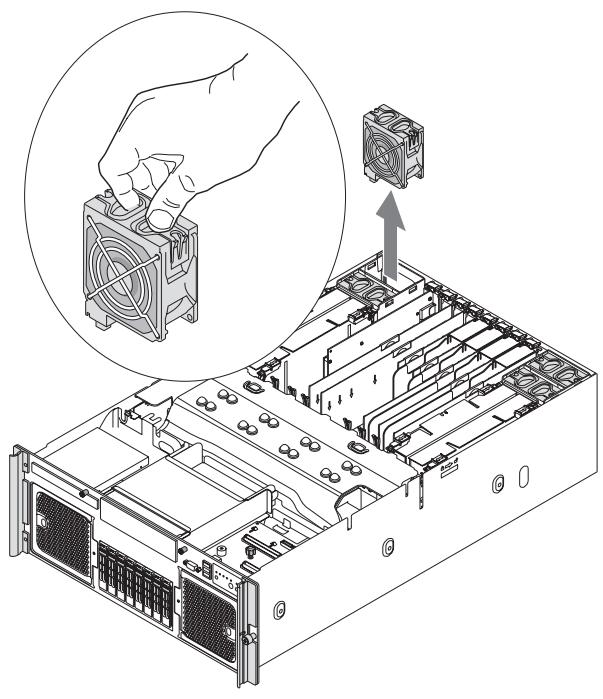
Figure 16. Removing a Rear System Fan
- Lower the replacement fan into the fan bay.
- Push down on the fan until it clicks into place.
Hot-swapping Hard Disk Drives
The server supports five hot-swap drive carriers. Each carrier holds a standard one-inch high SCSI-2 or SCSI-3 hard drive.
The procedures in this section describe how to determine drive status, remove a faulty drive, and install a new drive. If a drive is in a redundant configuration, you can install or replace a hot-swap hard disk drive without powering down the server.

CAUTION
To ensure proper airflow and server cooling, all drive bays must contain either a carrier with a hard drive installed in it or a carrier with an air baffle installed.
Determining Drive Status
The drive carriers contain light-pipes that allow dual-color LED indicators to show through the bezel to display the hard disk drive status, as shown by Figure 17.
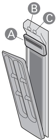
Figure 17. Hard Disk Drive Carrier
Table 15. Hard Disk Drive Carrier
| Item | Description |
| A | Latch |
| B | Activity LED (green) • On: SAS drive installed and working correctly • Blinking: Hard drive is active |
| C | Fault LED (amber) • On: Hard drive or slot failure • Slow blinking (~1 Hz): Predictive hard drive / slot failure or rebuild in process • Fast blink (~2.5 Hz): Hard drive rebuild interrupted or rebuild on empty slot |
Removing a Hard Disk Drive
- Observe the safety, ESD, and other precautions described in "Safety Information."
- Press on the green drive carrier latch.
- Pull the handle to remove the drive cage from the chassis.
- Place the drive cage on a clean, static-free work surface.
Mounting a Hard Disk Drive in a Carrier
To mount a hard drive in a carrier:
- Observe the safety, ESD, and other precautions described in "Safety Information."
- Remove the hard disk drive from the protective wrapper and place it on a clean ESD-protected work surface.
- Set any jumpers and/or switches on the drive according to the drive manufacturer's instructions.
- If the drive carrier is installed in the chassis, remove it and place it on a clean static-free work surface. For instructions, see "Removing a Hard Disk Drive".
- Remove the four screws that hold the air baffle in place.
- Remove the air baffle from the carrier.
- Store the air baffle for future reinstallation.
- Position the drive in the carrier with the label-side up and the connector end of the drive facing the back of the carrier.
- Align the holes in the drive to the holes in the drive carrier slide track and insert the screws that you were attached to the air baffle.
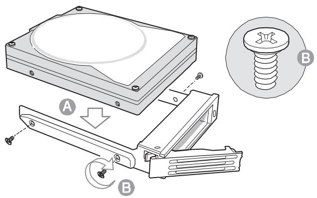
Figure 18. Attaching the Hard Drive to the Carrier
Installing a Hard Disk Drive Assembly
- Observe the safety, ESD, and other precautions described in "Safety Information".
- With the drive carrier handle fully open, slide the drive carrier all the way into the drive bay in the chassis.
- Use the handle to push the carrier until it docks in the chassis, then close the drive carrier handle.
Hot-swapping Power Supplies
If your server is configured with two power supplies, you can replace a failed or failing power supply without powering down the server.

CAUTION
Because of chassis airflow disruption, a power supply bay should never be vacant for more than two minutes when the server power is on. Exceeding five-minutes might cause the system to exceed the maximum acceptable temperature and possibly damage system components.
Removing a Power Supply

CAUTION
Any unoccupied power supply slots must be covered with a filler panel. Uncovered slots can disrupt the airflow used for cooling the system.
- Observe the safety, ESD, and other precautions described in "Safety Information".
- Remove the AC power cord from the power supply to be removed.
- Unscrew the thumb latch to unlock the power supply handle.
- Open the handle on the power supply.
- Pull the power supply from the chassis and set it on a clean, ESD-protected work surface.
- Install a replacement power supply or a filler panel. For instructions, see "Installing a Power Supply".
Installing a Power Supply
- Remove the new power supply from the protective packaging and place it on a clean ESD protected work surface.
- Remove the filler panel from the back of the chassis, if installed.
- Position the power supply with the handle at the right side of the power supply.
- Slide the new power supply partway into the power supply bay.
- With the handle in the open position, push the power supply fully into the bay until it stops.
- Rotate the handle to the closed position.
- Tighten the thumbscrew to secure the power supply.
- Plug the power cord into the AC receptacle on the power supply.
- Use the LEDs on the power supply to confirm the power supply is functioning.
Installing and Removing PCI Cards
This section outlines the procedures for performing a hot-plug operation with PCI cards and installing and removing non-hot-plug PCI cards. Cards can be hot-swapped in PCI slots 1 through 5. The server must be powered down to install or remove a card from PCI slots 6 and 7.
CAUTION
Expansion slot covers must be installed on all vacant slots to maintain the electromagnetic emission characteristics of the server and to ensure proper cooling of the system.
Removing Hot-plug PCI Card with Operating System Hot-Plug Interface
CAUTION
Only PCI add-in cards in PCI slots 1 and 2 are hot-swappable. If you are adding or removing a PCI card from PCI slots 3 through 7, see “Removing a Non-Hot-Plug PCI Card” and “Installing a Non-Hot-Plug PCI Card”.
- Observe the safety, ESD, and other precautions described in "Safety Information".
- Remove the top cover. For instructions, see "Removing the Top Cover".
- If you are using a Microsoft® Windows® operating system, double-click the “Unplug/Eject” icon in the taskbar to open the “Unplug or Eject Hardware” menu.
- Select the device to be removed and click "Stop".
- Wait for the PCI slot power LED at the rear of the slot to turn off.
- Disconnect any cables attached to the card.
- Rotate the retention latch at the rear of the card slot into the up position.
- If a long card is installed, press the blue plastic piece at the front of the card.
- Pull up on the card to remove it.
- Store the card in an antistatic protective wrapper.
-
Install an expansion slot cover over the empty slot or install a replacement PCI card:
-
To install an expansion slot cover: align the cover with the slot from the rear of the chassis. Press the cover into the slot. Rotate the bracket at the rear of the card slot into the down position.
-
To install a replacement PCI card: see "Installing a Hot-plug PCI Add-in Card".
-
Install the top cover. For instructions, see "Installing the Top Cover".
Removing Hot-plug PCI Card with Hardware Hot-Plug Interface

CAUTION
Only PCI add-in cards in PCI slots 1 and 2 are hot-swappable. If you are adding or removing a PCI card from PCI slots 3 through 7, see "Removing a Non-Hot-Plug PCI Card" and "Installing a Non-Hot-Plug PCI Card".
- Observe the safety precautions, warnings, and cautions described in "Safety Information".
- Remove the top cover. For instructions, see "Removing the Top Cover".
- Press the attention button for the slot.
NOTE
Press the attention button again within five seconds to abort the hot-plug operation.
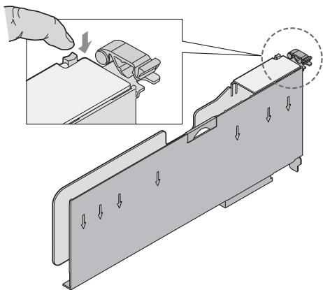
Figure 19. PCI Slot Attention Button
- Wait for the power LED on the slot to turn off.
- Disconnect any cables to the PCI card.
- Rotate the retention latch at the rear of the card slot into the up position.
- If a long card is installed, press the blue plastic piece at the front of the card.
- Pull up on the card to remove it.
-
Store the card in an anti-static bag.
-
Install an expansion slot cover over the empty slot or install a replacement PCI card:
-
To install an expansion slot cover: align the cover with the slot from the rear of the chassis. Press the cover into the slot. Rotate the retention latch at the rear of the board slot into the down position.
-
To install a replacement PCI card: see "Installing a Hot-plug PCI Add-in Card".
-
Install the top cover. For instructions see "Installing the Top Cover".
Installing a Hot-plug PCI Add-in Card

CAUTION
Only PCI add-in cards in PCI slots 1 and 2 are hot-swappable. If you are adding or removing a PCI card from PCI slots 3 through 7, see “Removing a Non-Hot-Plug PCI Card” and “Installing a Non-Hot-Plug PCI Card”.
- Observe the safety precautions, warnings, and cautions described in "Safety Information".
- If your server is operating, use your operating system or GUI application to power down the PCI slot.
- Remove the top cover. For instructions, see "Removing the Top Cover".
- Being careful not to touch the components or gold edge-connectors on the add-in card, remove the card from the anti-static bag, and place it on a clean, ESD-protected work surface.
- Rotate the retention latch at the rear of the card slot into the up position.
- If necessary, remove the expansion slot cover in the slot you are using by sliding it up from inside the chassis.
- Align and slide the adapter board down until it seats in its connector. If you are installing a full-length card, guide the front of the card into the appropriate slot.
- Press the card down firmly until it seats into the slot.

CAUTION
Some accessory/option board outputs exceed Class 2 or limited power source limits. Use appropriate interconnecting cabling in accordance with the national electrical code.
- Rotate the retention latch at the rear of the card slot into the down position.
- Connect any required cabling to the PCI add-in board.
-
If using the operating system hot-plug interface:
-
Wait for the software user interface to appear on your monitor and then confirm the device to be enabled.
- Wait for the power LED to turn on.
If using the hardware hot-plug interface:
- Press the attention button for the slot. If you need to abort the hotplug operation, press the attention button again within five seconds.
- Wait for power LED to turn on.

NOTE
For either the operating system interface or the hardware hot-plug interface, if the attention LED is blinking, a power fault has occurred. You may need to remove the adapter, wait for the LED to turn off, and re-start the hot insertion.
- Install the top cover. For instructions, see "Installing the Top Cover".
Removing a Non-Hot-Plug PCI Card
PCI cards installed in slots 1 and 2 are hot-swappable. If you are adding or removing a card from one of these slots, you can do so without powering down the server. If you wish to do so, follow the instructions under "Removing Hot-plug PCI Card with Operating System Hot-Plug Interface" or "Removing Hot-plug PCI Card with Hardware Hot-Plug Interface", and "Installing a Hot-plug PCI Add-in Card".

CAUTION
Damage to the system occurs if power is not removed from the system prior to removal or installation of non-hot-plug boards.
- Observe the safety precautions, warnings, and cautions described in "Safety Information".
- Turn off all peripheral devices connected to the system.
- Power down the system and unplug both AC power cords to remove power from the server.
- Remove the top cover. For instructions, see "Removing the Top Cover".
- Disconnect any cables attached to the PCI card.
- Rotate the retention latch at the rear of the card slot into the up position.
- Pull up on the card to remove it.
- Place the PCI card on a clean, static-free work surface or inside a static-free plastic bag.
-
Install an expansion slot cover over the empty slot or install a replacement PCI card:
-
To install an expansion slot cover: align the cover with the slot from the rear of the chassis. Press the cover into the slot. Rotate the bracket at the rear of the chassis into the down position.
-
To install a replacement PCI card: see "Installing a Non-Hot-Plug PCI Card".
-
Install the top cover. For instructions, see "Installing the Top Cover".
Installing a Non-Hot-Plug PCI Card
- Observe the safety precautions, warnings, and cautions described in "Safety Information"
- Turn off all peripheral devices connected to the system.
- Power down the system and unplug both AC power cords.
- Remove the top cover. For instructions, see "Removing the Top Cover".
- Being careful not to touch the components or the gold edge connectors on the PCI card, remove it from its protective wrapper. Place the card component-side up on a clean, static free work surface.
- Rotate the retention latch at the rear of the card slot into the up position.
- If necessary, remove the expansion slot cover in the slot you are using by sliding it up from inside the chassis.
- Align and slide the adapter board down until it seats in its connector. If you are installing a full-length card, guide the front of the card into the appropriate slot.
- Press the card down firmly until it seats into the slot.
- Rotate the retention latch at the rear of the card slot into the down position.
- Attach the required cables to the PCI card.
- Install the top cover. For instructions, see "Installing the Top Cover".
Installing and Removing Memory Boards
At least one memory board and one DIMM must be installed for the server to function. Supported memory board configurations are as follows:
One memory board installed in Slot A, at the right side of the system
- Two memory boards, installed in Slots A and B, the two boards at the right side of the system
All four memory boards, Slots A, B, C, and D
AC power must be removed from the system before servicing the memory boards.
Removing a Memory Board
- Remove the top cover. For instructions, see "Removing the Top Cover".
- Rotate the latches on the memory board upward to disengage the memory board from the main board. See letters “A” and “B” in the following figure.
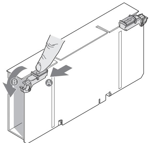
Figure 20. Opening Memory Board Latches
- Lift the memory board by the latches to pull it from the server.
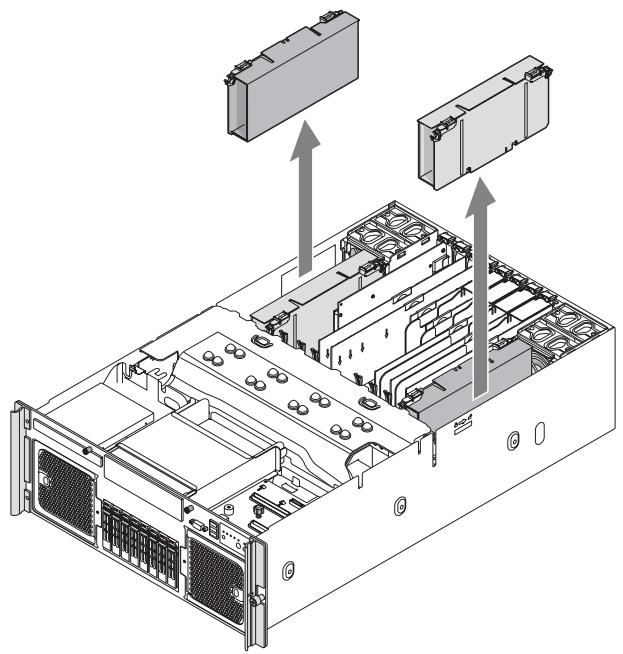
Figure 21. Removing a Memory Board
Installing a Memory Board
- Ensure the latches on the memory board are in the open / up position.
- Align the edges of the board in the card guides and slide the memory board into the main board.
- Once the board is lowered as far as possible, rotate the latches downward to firmly engage the board into the memory board slot.
- Install the top cover. For instructions, see "Installing the Top Cover".
Installing and Removing DIMMs
Memory Population Rules
- Memory must be populated beginning with memory board A, slot 1. This is DIMM Slot A1. Memory board A is at the right side of the system.
- To increase memory capacity, additional memory can be added to memory board A beginning with slot A2, and followed by slot A3 and then slot A4.
- To ensure proper system thermal performance, all DIMM slots must be populated with either a DIMM or a DIMM blank.
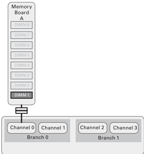
Figure 22. Minimum Memory Population
If only memory boards A and B are installed:
- Identically numbered FBDIMM sockets for both memory boards must be populated with FBDIMMs identical in terms of timing, technology, and size. For example, DIMM A1 and B1 must be identical.
- FBDIMMs installed in different socket positions (numbers) on a riser board do not need to be identical for dual-channel operation. For example, DIMMs A1 and B1 can be different from DIMMs A2 and B2.
Additional memory can be added by installing identical pairs of DIMMs in the lowest numbered available slots.
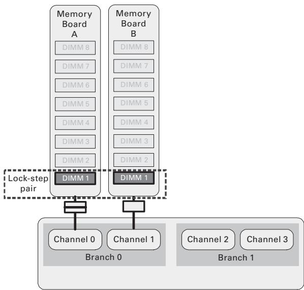
Figure 23. Memory Board A and B Population
If memory boards A, B, C and D are installed:
- Identically numbered FBDIMM sockets for both memory boards in a branch must be populated with FBDIMMs identical in terms of timing, technology, and size. For example, DIMM A1 and B1 must be identical, and DIMM C1 and D1 must be identical.
- FBDIMMs installed in different socket positions (numbers) on a memory board do not need to be identical. For example, DIMMs A1 and B1 can be different from DIMMs A2 and B2.
- If memory mirroring is not required, FBDIMMs installed in the same socket positions (numbers) across the two branches do not need to be identical. For example, DIMMs A1 and B1 can be different from DIMMs C1 and D1.
- If memory mirroring is required, FBDIMMs installed in the same socket positions (numbers) across the two branches must be identical. For example, DIMMs A1 and B1 must be identical to DIMMs C1 and D1.
Additional memory can be added by installing identical pairs of DIMMs in the lowest numbered available slots.
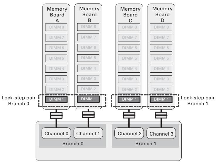
Figure 24. Memory Board A, B, C, D Population
Installing DIMMs

Cautions
- Use extreme care when installing a DIMM. Applying too much pressure can damage the connector. DIMMs are keyed and can be inserted in only one way.
- Hold DIMMs only by the edges. Do not touch the components or gold edge connectors.
Install DIMMs with gold-plated edge connectors only. -
The maximum DIMM height is 4.445 ~cm (1.75 inches). Do not install DIMMs that exceed this height.
-
Remove the top cover. For instructions, see "Removing the Top Cover".
- Remove the memory board. For instructions, see "Removing a Memory Board".
- Press down on the hooks on the underside of the memory board to disengage them. See letter "A" in the following figure.
- Lift the memory board DIMM cover from the memory board.
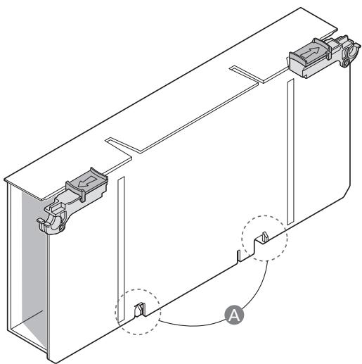
Figure 25. Remove Memory Board DIMM Cover
- Open the plastic levers on each end of the DIMM socket(s). Remove the DIMM from its antistatic container. Hold the DIMM only by the edges. Do not touch the components or gold edge connectors.
- Install DIMMs in the correct order. See "Memory Population Rules".
- Position the DIMM above the socket. Align the notch on the bottom edge of the DIMM with the key in the DIMM socket.
- Insert the bottom edge of the DIMM into the socket.
- Push down on the top edge of the DIMM. The levers at each end of the DIMM socket will close. Make sure the levers close securely.
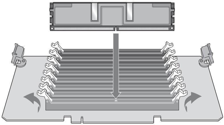
Figure 26. Install DIMMs
- Lower the memory board DIMM cover over the DIMM slots.
- Line up the hooks in the cover with the notches on the bottom edge of the memory board.
- Press down on the cover until the hooks on both the top and bottom of the cover click into place around the memory board.
- Install the memory board. For instructions, see "Installing a Memory Board".
Removing DIMMs

Caution
Use extreme care when removing DIMMs. Too much pressure can damage the connector. Apply only enough pressure on the plastic levers to release the DIMM.
- Remove the top cover. For instructions, see "Removing the Top Cover".
- Remove the memory board. For instructions, see "Removing a Memory Board".
- Press down on the hooks on the underside of the memory board to disengage them.
- Lift the memory board DIMM cover from the memory board.
- Open the plastic levers on each end of the DIMM socket(s). The DIMM will lift from the socket.
- Hold the DIMM only by the edges. Do not touch the DIMM components or the gold edge connectors. Store it in an antistatic bag.
- Install replacement DIMMs if necessary. For instructions, see "Installing DIMMs".
- Install the memory board. For instructions, see "Installing a Memory Board".
6 Replacing the CMOS Battery
The lithium battery on the Main Board powers the real-time clock (RTC) for three to four years in the absence of power. When the battery weakens, it loses voltage and the system settings stored in CMOS RAM and the Real Time Clock (such as the date and time) can be wrong. Contact your customer service representative or dealer for a list of approved replacement batteries.
The following warning and translations are required by specific certifying agencies to be printed immediately adjacent to the procedure for removing the battery.
CAUTION
Risk of explosion if the battery is replaced with an incorrect type. Batteries should be recycled where possible. Disposal of used batteries must be in accordance with local environmental regulations.
VORSICHT
- Observe the safety precautions, warnings, and cautions described in "Safety Information".
- Turn off all peripheral devices connected to the system.
- Power down the system and unplug both AC power cords.
- Remove the top cover. For instructions, see "Removing the Top Cover".
- Remove the Memory Board or the Memory Board air baffle from Slot A to expose the battery. For instructions, see "Cold Removal of Memory Board".
- Place your finger on the edge of the battery, between the two smaller prongs that hold the battery in place.
- Without pulling up on the battery, push the battery toward the larger prongs until the edge of the battery clears the small prongs.
- Maintain pressure on the battery while pulling up on the released edge of the battery to lift it from the server. See Figure 27.

CAUTION
Do not attempt to pull the battery up until it is pushed clear of the smaller prongs. Doing so may damage the battery holder on the Main Board.
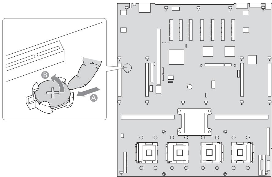
Figure 27. Removing the Battery
- Dispose of the battery according to local ordinance.
- Remove the new lithium battery from its package.
- Being careful to observe the correct polarity, insert the battery at an angle into the battery socket with the edge of the battery under the larger prongs in the battery socket.
- Push the battery toward the larger prongs while pushing down on the raised edge of the battery until it clicks into place under all four prongs.
- Install the Memory Board or the Memory Board air baffle into slot A. For instructions, see "Cold Insertion of a Memory Board".
- Install the top cover. For instructions, see "Installing the Top Cover".
7 Regulatory and Integration Information
Product Regulatory Compliance
Product Safety Compliance
The server board complies with the following safety requirements:
EN 60950 (European Union)
IEC 60950 (International)
CE - Low Voltage Directive (73/23/EEC) (European Union)
Product RoHS Compliance
Restriction of Hazardous Substances: This server system is compliant to European Directive 2002/95/EC (RoHS).
Product EMC Compliance
The server board has been has been tested and verified to comply with the following electromagnetic compatibility (EMC) regulations when installed a compatible host system.
CISPR 22, 3rd Edition (Class A) - Radiated & Conducted Emissions (International)
EN 55022 (Class A) - Radiated & Conducted Emissions (European Union)
EN 55024 (Immunity) (European Union)
CE-EMC Directive (89/336/EEC) (European Union)
Product Regulatory Compliance Markings
This product is marked with the following Product Certification Markings:
Table 16. Product Certification Markings
| CE Mark | CE |
Electromagnetic Compatibility Notices
Europe (CE Declaration of Conformity)
This product has been tested in accordance to, and complies with the Low Voltage Directive (73/23/ EEC) and EMC Directive (89/336/EEC). The product has been marked with the CE Mark to illustrate its compliance.
Appendix A: POST Codes
The system BIOS displays error messages on the video screen. Before video initialization, beep codes inform you of errors. POST error codes are logged in the event log. The BIOS displays POST error codes on the video monitor.
Eight light-emitting diodes indicate the raw binary output of port 80 values. These LEDs are arranged so you can see a direct correlation to the binary equivalent. The table shows the correlation of port 80 post code bit to LED reference designator.
Table 17. Port 80 POST Code LEDs
POST Progress Codes and Messages
The system BIOS complies with the EFI Framework POST Progress Code specification by reporting 32-bit status codes at various points during POST that contain class, subclass, and operation information. The class and subclass fields describe the type of hardware that is being initialized. The operation field represents the specific initialization activity.
The system BIOS truncates 32-bit EFI POST Progress Codes to 8-bit values for display on the system board Diagnostic LED array. The resulting 8-bit POST code is displayed on the system board POST Code Diagnostic LED array at the start of each configuration process. This information can be used to assist with debugging system hangs during POST by identifying the last POST process initiated by the BIOS.
Table 18. POST Progress Codes and Messages
| Progress Code | Progress Code Meaning |
| Host Processor | |
| 0x10 | Power-on initialization of the host processor (Boot Strap Processor) |
| 0x11 | Host processor cache initialization (including AP) |
| 0x12 | Starting Application processor initialization |
| 0x13 | SMM initialization |
| Chipset | |
| 0x21 | Initializing a chipset component |
| Memory | |
| 0xE1 | No memory available (system halted) |
| 0xE4 | BIOS cannot communicate with FBDIMM (serial channel hardware failure) |
| 0xE6 | FBDIMM(s) failed Memory iBIST or Memory LinkTraining failure |
| 0xE8 | FBDIMM with corrupted SPD data detected (system halted) |
| 0x22 | Reading configuration data from memory (SPD on DIMM) |
| 0x23 | Detecting presence of memory |
| 0x24 | Programming timing parameters in the memory controller |
| 0x25 | Configuring memory parameters in the memory controller |
| 0x26 | Optimizing memory controller settings |
| 0x27 | Initializing memory, such as ECC init |
| 0x28 | Testing memory |
| PCI Bus | |
| 0x50 | Enumerating PCI buses |
| 0x51 | Allocating resources to PCI buses |
| 0x52 | Hot Plug PCI controller initialization |
| 0x53-0x57 | Reserved for PCI Bus |
| USB | |
| 0x58 | Resetting USB bus |
| 0x59 | Reserved for USB devices |
| ATA / ATAPI / SATA | |
| 0x5A | Resetting PATA / SATA bus and all devices |
| 0x5B | Reserved for ATA |
| SMBUS | |
| 0x5C | Resetting SMBUS |
| 0x5D | Reserved for SMBUS |
| Local Console | |
| 0x70 | Resetting the video controller (VGA) |
| 0x71 | Disabling the video controller (VGA) |
| 0x72 | Enabling the video controller (VGA) |
| Remote Console | |
| 0x78 | Resetting the console controller |
| 0x79 | Disabling the console controller |
| 0x7A | Enabling the console controller |
| Keyboard (USB only) | |
| 0x90 | Resetting the keyboard |
| 0x91 | Disabling the keyboard |
| 0x92 | Detecting the presence of the keyboard |
| 0x93 | Enabling the keyboard |
| 0x94 | Clearing keyboard input buffer |
| 0x95 | Instructing keyboard controller to run self-test (PS2 only) |
| Mouse (USB only) | |
| 0x98 | Resetting the mouse |
| 0x99 | Detecting the mouse |
| 0x9A | Detecting the presence of mouse |
| 0x9B | Enabling the mouse |
| Fixed Media | |
| 0xB0 | Resetting fixed media device |
| 0xB1 | Disabling fixed media device |
| 0xB2 | Detecting presence of a fixed media device (IDE hard drive detection, etc.) |
| 0xB3 | Enabling / configuring a fixed media device |
| Removable Media | |
| 0xB8 | Resetting removable media device |
| 0xB9 | Disabling removable media device |
| 0xB4 | Detecting presence of a removable media device (IDE CDROM detection, etc.) |
| 0xBC | Enabling / configuring a removable media device |
| Boot Device Selection | |
| 0xDy | Trying boot selection y (where y = 0 to F) |
| Pre-EFI Initialization (PEI) Core | |
| 0xE0 | Started dispatching early initialization modules (PEIM) |
| 0xE2 | Initial memory found, configured, and installed correctly |
| 0xE1,0xE3 | Reserved for initialization module use (PEIM) |
| Driver Execution Environment (DXE) Core | |
| 0xE4 | Entered EFI driver execution phase (DXE) |
| 0xE5 | Started dispatching drivers |
| 0xE6 | Started connecting drivers |
| DXE Drivers | |
| 0xE7 | Waiting for user input |
| 0xE8 | Checking password |
| 0xE9 | Entering BIOS setup |
| 0xA | Flash Update |
| 0xEE | Calling Int 19. One beep unless silent boot is enabled. |
| 0xEF | Unrecoverable boot failure |
| Runtime Phase / EFI Operating System Boot | |
| 0xF4 | Entering sleep state |
| 0xF5 | Exiting sleep state |
| 0xF8 | Operating system has requested EFI to close boot services (ExitBootServices() has been called) |
| 0xF9 | Operating system has switched to virtual address mode (SetVirtualAddressMap() has been called) |
| 0xAA | Operating system has requested a system reset (ResetSystem() has been called) |
| Pre-EFI Initialization Module (PEIM) / Recovery | |
| 0x30 | Crisis recovery has been initiated because of a user request |
| 0x31 | Crisis recovery has been initiated by software (corrupt flash) |
| 0x34 | Loading crisis recovery capsule |
| 0x35 | Handling off control to the crisis recovery capsule |
| 0x3F | Unable to complete crisis recovery. |
POST Error Messages and Handling
The POST Error Manager displays error messages reported by the system BIOS during POST. The system BIOS truncates the 32-bit EFI POST Progress Code associated with the error to 16-bit values for display in the POST Error Manager.
The POST Error Manager behavior in response to the error is defined by the error severity reported by the BIOS. Errors are categorized in one of three severity levels. The system behavior in response to severity level of:
Fatal
- The BIOS logs an error to the POST Error Manager.
- The BIOS logs an error message to the BMC System Event Log (SEL).
- The BIOS unconditionally enters POST Error Manager to display error message.
- The BIOS halts the system to prevent boot.
- The user needs to replace the faulty part and restart the system.
Major
- The BIOS logs an error to the POST Error Manager.
- The BIOS logs an error message to the BMC System Event Log (SEL).
- The BIOS continues booting in a degraded state by default (i.e. BIOS does not automatically enter the POST Error Manager to display the error message).
- The user can override this default behavior by configuring the BIOS Setup POST Error Pause option to Enabled. This forces the system to enter the POST Error Manager and display the error message before booting.
- The user can choose to take immediate corrective action or continue booting.
Minor
- The BIOS logs an error to the POST Error Manager.
- The BIOS continues booting with a degraded state (i.e. BIOS does not automatically enter the POST Error Manager to display the error message).
- The user may want to replace the erroneous unit.
The POST Error Manager reports a maximum of 500 errors on any single boot cycle. Errors are automatically cleared from the Error Manager on each boot.
Table 19. POST Error Manager Messages and Handling
| POST Error Code | POST Error Manager Message | Severity |
| 0012 | CMOS date / time not set | Major |
| 004C | Keyboard / interface error | Major |
| 0108 | Keyboard component encountered a locked error. | Minor |
| 0109 | Keyboard component encountered a stuck key error. | Minor |
| 0113 | Fixed Media: The SAS RAID firmware can not run properly. The user should attempt to reflash the firmware. | Major |
| 0140 | PCI component encountered a PERR error. | Major |
| 0141 | PCI resource conflict | Major |
| 0146 | PXI out of resources error | Major |
| 0192 | Cache size mismatch | Fatal |
| 0194 | CPUID, processor family are different | Fatal |
| 0195 | Front side bus mismatch | Fatal |
| 0196 | Processor Model mismatch | Major |
| 0197 | Processor speeds mismatched | Fatal |
| 0198 | Processor family is unsupported | Major |
| 019A | Processor voltage mismatch detected | Fatal |
| 5220 | CMOS / NVRAM configuration cleared | Major |
| 5221 | Passwords cleared by jumper | Major |
| 5224 | Password clear jumper is set | Major |
| 8110 | Processor 01 internal error (IERR) on last boot | Major |
| 8111 | Processor 02 internal error (IERR) on last boot | Major |
| 8112 | Processor 03 internal error (IERR) on last boot | Major |
| 8113 | Processor 04 internal error (IERR) on last boot | Major |
| 8120 | Processor 01 thermal trip error on last boot | Major |
| 8121 | Processor 02 thermal trip error on last boot | Major |
| 8122 | Processor 03 thermal trip error on last boot | Major |
| 8123 | Processor 04 thermal trip error on last boot | Major |
| 8130 | Processor 01 disabled | Minor |
| 8131 | Processor 02 disabled | Minor |
| 8132 | Processor 03 disabled | Minor |
| 8133 | Processor 04 disabled | Minor |
| 8160 | Processor 01 unable to apply microcode update | Major |
| 8161 | Processor 02 unable to apply microcode update | Major |
| 8162 | Processor 03 unable to apply microcode update | Major |
| 8163 | Processor 04 unable to apply microcode update | Major |
| 8180 | Processor 01 microcode update not found | Minor |
| 8181 | Processor 02 microcode update not found | Minor |
| 8182 | Processor 03 microcode update not found | Minor |
| 8183 | Processor 04 microcode update not found | Minor |
| 8190 | Watchdog timer failed on last boot | Major |
| 8198 | Operating system boot watchdog timer expired on last boot | Major |
| 8300 | Baseboard management controller failed self-test | Major |
| 8305 | Hot-swap controller failed | Major |
| 84F2 | Baseboard management controller failed to respond | Major |
| 84F3 | Baseboard management controller in update mode | Major |
| 84F4 | Sensor data record empty | Major |
| 84FF | System event log full | Minor |
| 8500 | Memory component could not be configured in the selected RAS mode | Major |
| 8520 | Memory failed SelfTest (BIST). Memory Board A, DIMM_1. | Major |
| 8521 | Memory failed SelfTest (BIST). Memory Board A, DIMM_2. | Major |
| 8522 | Memory failed SelfTest (BIST). Memory Board A, DIMM_3. | Major |
| 8523 | Memory failed SelfTest (BIST). Memory Board A, DIMM_4. | Major |
| 8524 | Memory failed SelfTest (BIST). Memory Board A, DIMM_5. | Major |
| 8525 | Memory failed SelfTest (BIST). Memory Board A, DIMM_6. | Major |
| 8526 | Memory failed SelfTest (BIST). Memory Board A, DIMM_7. | Major |
| 8527 | Memory failed SelfTest (BIST). Memory Board A, DIMM_8. | Major |
| 8528 | Memory failed SelfTest (BIST). Memory Board B, DIMM_1. | Major |
| 8529 | Memory failed SelfTest (BIST). Memory Board B, DIMM_2. | Major |
| 852A | Memory failed SelfTest (BIST). Memory Board B, DIMM_3. | Major |
| 852B | Memory failed SelfTest (BIST). Memory Board B, DIMM_4. | Major |
| 852C | Memory failed SelfTest (BIST). Memory Board B, DIMM_5. | Major |
| 852D | Memory failed SelfTest (BIST). Memory Board B, DIMM_6. | Major |
| 852E | Memory failed SelfTest (BIST). Memory Board B, DIMM_7. | Major |
| 852F | Memory failed SelfTest (BIST). Memory Board B, DIMM_8. | Major |
| 8530 | Memory failed SelfTest (BIST). Memory Board C, DIMM_1. | Major |
| 8531 | Memory failed SelfTest (BIST). Memory Board C, DIMM_2. | Major |
| 8532 | Memory failed SelfTest (BIST). Memory Board C, DIMM_3. | Major |
| 8533 | Memory failed SelfTest (BIST). Memory Board C, DIMM_4. | Major |
| 8534 | Memory failed SelfTest (BIST). Memory Board C, DIMM_5. | Major |
| 8535 | Memory failed SelfTest (BIST). Memory Board C, DIMM_6. | Major |
| 8536 | Memory failed SelfTest (BIST). Memory Board C, DIMM_7. | Major |
| 8537 | Memory failed SelfTest (BIST). Memory Board C, DIMM_8. | Major |
| 8538 | Memory failed SelfTest (BIST). Memory Board D, DIMM_1. | Major |
| 8539 | Memory failed SelfTest (BIST). Memory Board D, DIMM_2. | Major |
| 853A | Memory failed SelfTest (BIST). Memory Board D, DIMM_3. | Major |
| 853B | Memory failed SelfTest (BIST). Memory Board D, DIMM_4. | Major |
| 853C | Memory failed SelfTest (BIST). Memory Board D, DIMM_5. | Major |
| 853D | Memory failed SelfTest (BIST). Memory Board D, DIMM_6. | Major |
| 853E | Memory failed SelfTest (BIST). Memory Board D, DIMM_7. | Major |
| 853F | Memory failed SelfTest (BIST). Memory Board D, DIMM_8. | Major |
| 8540 | Memory Board A, DIMM_1 Disabled | Major |
| 8541 | Memory Board A, DIMM_2 Disabled | Major |
| 8542 | Memory Board A, DIMM_3 Disabled | Major |
| 8543 | Memory Board A, DIMM_4 Disabled | Major |
| 8544 | Memory Board A, DIMM_5 Disabled | Major |
| 8545 | Memory Board A, DIMM_6 Disabled | Major |
| 8546 | Memory Board A, DIMM_7 Disabled | Major |
| 8547 | Memory Board A, DIMM_8 Disabled | Major |
| 8548 | Memory Board B, DIMM_1 Disabled | Major |
| 8549 | Memory Board B, DIMM_2 Disabled | Major |
| 854A | Memory Board B, DIMM_3 Disabled | Major |
| 854B | Memory Board B, DIMM_4 Disabled | Major |
| 854C | Memory Board B, DIMM_5 Disabled | Major |
| 854D | Memory Board B, DIMM_6 Disabled | Major |
| 854E | Memory Board B, DIMM_7 Disabled | Major |
| 854F | Memory Board B, DIMM_8 Disabled | Major |
| 8550 | Memory Board C, DIMM_1 Disabled | Major |
| 8551 | Memory Board C, DIMM_2 Disabled | Major |
| 8552 | Memory Board C, DIMM_3 Disabled | Major |
| 8553 | Memory Board C, DIMM_4 Disabled | Major |
| 8554 | Memory Board C, DIMM_5 Disabled | Major |
| 8555 | Memory Board C, DIMM_6 Disabled | Major |
| 8556 | Memory Board C, DIMM_7 Disabled | Major |
| 8557 | Memory Board C, DIMM_8 Disabled | Major |
| 8558 | Memory Board D, DIMM_1 Disabled | Major |
| 8559 | Memory Board D, DIMM_2 Disabled | Major |
| 855A | Memory Board D, DIMM_3 Disabled | Major |
| 855B | Memory Board D, DIMM_4 Disabled | Major |
| 855C | Memory Board D, DIMM_5 Disabled | Major |
| 855D | Memory Board D, DIMM_6 Disabled | Major |
| 855E | Memory Board D, DIMM_7 Disabled | Major |
| 855F | Memory Board D, DIMM_8 Disabled | Major |
| 8560 | Memory Board A, DIMM_1 Component encountered a Serial Presence Detection (SPD) fail error | Major |
| 8561 | Memory Board A, DIMM_2 Component encountered a Serial Presence Detection (SPD) fail error | Major |
| 8562 | Memory Board A, DIMM_3 Component encountered a Serial Presence Detection (SPD) fail error | Major |
| 8563 | Memory Board A, DIMM_4 Component encountered a Serial Presence Detection (SPD) fail error | Major |
| 8564 | Memory Board A, DIMM_5 Component encountered a Serial Presence Detection (SPD) fail error | Major |
| 8565 | Memory Board A, DIMM_6 Component encountered a Serial Presence Detection (SPD) fail error | Major |
| 8566 | Memory Board A, DIMM_7 Component encountered a Serial Presence Detection (SPD) fail error | Major |
| 8567 | Memory Board A, DIMM_8 Component encountered a Serial Presence Detection (SPD) fail error | Major |
| 8568 | Memory Board B, DIMM_1 Component encountered a Serial Presence Detection (SPD) fail error | Major |
| 8569 | Memory Board B, DIMM_2 Component encountered a Serial Presence Detection (SPD) fail error | Major |
| 856A | Memory Board B, DIMM_3 Component encountered a Serial Presence Detection (SPD) fail error | Major |
| 856B | Memory Board B, DIMM_4 Component encountered a Serial Presence Detection (SPD) fail error | Major |
| 856C | Memory Board B, DIMM_5 Component encountered a Serial Presence Detection (SPD) fail error | Major |
| 856D | Memory Board B, DIMM_6 Component encountered a Serial Presence Detection (SPD) fail error | Major |
| 856E | Memory Board B, DIMM_7 Component encountered a Serial Presence Detection (SPD) fail error | Major |
| 856F | Memory Board B, DIMM_8 Component encountered a Serial Presence Detection (SPD) fail error | Major |
| 8570 | Memory Board C, DIMM_1 Component encountered a Serial Presence Detection (SPD) fail error | Major |
| 8571 | Memory Board C, DIMM_2 Component encountered a Serial Presence Detection (SPD) fail error | Major |
| 8572 | Memory Board C, DIMM_3 Component encountered a Serial Presence Detection (SPD) fail error | Major |
| 8573 | Memory Board C, DIMM_4 Component encountered a Serial Presence Detection (SPD) fail error | Major |
| 8574 | Memory Board C, DIMM_5 Component encountered a Serial Presence Detection (SPD) fail error | Major |
| 8575 | Memory Board C, DIMM_6 Component encountered a Serial Presence Detection (SPD) fail error | Major |
| 8576 | Memory Board C, DIMM_7 Component encountered a Serial Presence Detection (SPD) fail error | Major |
| 8577 | Memory Board C, DIMM_8 Component encountered a Serial Presence Detection (SPD) fail error | Major |
| 8578 | Memory Board D, DIMM_1 Component encountered a Serial Presence Detection (SPD) fail error | Major |
| 8579 | Memory Board D, DIMM_2 Component encountered a Serial Presence Detection (SPD) fail error | Major |
| 857A | Memory Board D, DIMM_3 Component encountered a Serial Presence Detection (SPD) fail error | Major |
| 857B | Memory Board D, DIMM_4 Component encountered a Serial Presence Detection (SPD) fail error | Major |
| 857C | Memory Board D, DIMM_5 Component encountered a Serial Presence Detection (SPD) fail error | Major |
| 857D | Memory Board D, DIMM_6 Component encountered a Serial Presence Detection (SPD) fail error | Major |
| 857E | Memory Board D, DIMM_7 Component encountered a Serial Presence Detection (SPD) fail error | Major |
| 857F | Memory Board D, DIMM_8 Component encountered a Serial Presence Detection (SPD) fail error | Major |
| 8580 | Memory Board A, DIMM_1 Correctable ECC error encountered | Minor, Major after 10 |
| 8581 | Memory Board A, DIMM_2 Correctable ECC error encountered | Minor, Major after 10 |
| 8582 | Memory Board A, DIMM_3 Correctable ECC error encountered | Minor, Major after 10 |
| 8583 | Memory Board A, DIMM_4 Correctable ECC error encountered | Minor, Major after 10 |
| 8584 | Memory Board A, DIMM_5 Correctable ECC error encountered | Minor, Major after 10 |
| 8585 | Memory Board A, DIMM_6 Correctable ECC error encountered | Minor, Major after 10 |
| 8586 | Memory Board A, DIMM_7 Correctable ECC error encountered | Minor, Major after 10 |
| 8587 | Memory Board A, DIMM_8 Correctable ECC error encountered | Minor, Major after 10 |
| 8588 | Memory Board B, DIMM_1 Correctable ECC error encountered | Minor, Major after 10 |
| 8589 | Memory Board B, DIMM_2 Correctable ECC error encountered | Minor, Major after 10 |
| 858A | Memory Board B, DIMM_3 Correctable ECC error encountered | Minor, Major after 10 |
| 858B | Memory Board B, DIMM_4 Correctable ECC error encountered | Minor, Major after 10 |
| 858C | Memory Board B, DIMM_5 Correctable ECC error encountered | Minor, Major after 10 |
| 858D | Memory Board B, DIMM_6 Correctable ECC error encountered | Minor, Major after 10 |
| 858E | Memory Board B, DIMM_7 Correctable ECC error encountered | Minor, Major after 10 |
| 858F | Memory Board B, DIMM_8 Correctable ECC error encountered | Minor, Major after 10 |
| 8590 | Memory Board C, DIMM_1 Correctable ECC error encountered | Minor, Major after 10 |
| 8591 | Memory Board C, DIMM_2 Correctable ECC error encountered | Minor, Major after 10 |
| 8592 | Memory Board C, DIMM_3 Correctable ECC error encountered | Minor, Major after 10 |
| 8593 | Memory Board C, DIMM_4 Correctable ECC error encountered | Minor, Major after 10 |
| 8594 | Memory Board C, DIMM_5 Correctable ECC error encountered | Minor, Major after 10 |
| 8595 | Memory Board C, DIMM_6 Correctable ECC error encountered | Minor, Major after 10 |
| 8596 | Memory Board C, DIMM_7 Correctable ECC error encountered | Minor, Major after 10 |
| 8597 | Memory Board C, DIMM_8 Correctable ECC error encountered | Minor, Major after 10 |
| 8598 | Memory Board D, DIMM_1 Correctable ECC error encountered | Minor, Major after 10 |
| 8599 | Memory Board D, DIMM_2 Correctable ECC error encountered | Minor, Major after 10 |
| 859A | Memory Board D, DIMM_3 Correctable ECC error encountered | Minor, Major after 10 |
| 859B | Memory Board D, DIMM_4 Correctable ECC error encountered | Minor, Major after 10 |
| 859C | Memory Board D, DIMM_5 Correctable ECC error encountered | Minor, Major after 10 |
| 859D | Memory Board D, DIMM_6 Correctable ECC error encountered | Minor, Major after 10 |
| 859E | Memory Board D, DIMM_7 Correctable ECC error encountered | Minor, Major after 10 |
| 859F | Memory Board D, DIMM_8 Correctable ECC error encountered | Minor, Major after 10 |
| 85A0 | Memory Board A, DIMM_1 Uncorrectable ECC error encountered | Major |
| 85A1 | Memory Board A, DIMM_2 Uncorrectable ECC error encountered | Major |
| 85A2 | Memory Board A, DIMM_3 Uncorrectable ECC error encountered | Major |
| 85A3 | Memory Board A, DIMM_4 Uncorrectable ECC error encountered | Major |
| 85A4 | Memory Board A, DIMM_5 Uncorrectable ECC error encountered | Major |
| 85A5 | Memory Board A, DIMM_6 Uncorrectable ECC error encountered | Major |
| 85A6 | Memory Board A, DIMM_7 Uncorrectable ECC error encountered | Major |
| 85A7 | Memory Board A, DIMM_8 Uncorrectable ECC error encountered | Major |
| 85A8 | Memory Board B, DIMM_1 Uncorrectable ECC error encountered | Major |
| 85A9 | Memory Board B, DIMM_2 Uncorrectable ECC error encountered | Major |
| 85AA | Memory Board B, DIMM_3 Uncorrectable ECC error encountered | Major |
| 85AB | Memory Board B, DIMM_4 Uncorrectable ECC error encountered | Major |
| 85AC | Memory Board B, DIMM_5 Uncorrectable ECC error encountered | Major |
| 85AD | Memory Board B, DIMM_6 Uncorrectable ECC error encountered | Major |
| 85AE | Memory Board B, DIMM_7 Uncorrectable ECC error encountered | Major |
| 85AF | Memory Board B, DIMM_8 Uncorrectable ECC error encountered | Major |
| 85B0 | Memory Board C, DIMM_1 Uncorrectable ECC error encountered | Major |
| 85B1 | Memory Board C, DIMM_2 Uncorrectable ECC error encountered | Major |
| 85B2 | Memory Board C, DIMM_3 Uncorrectable ECC error encountered | Major |
| 85B3 | Memory Board C, DIMM_4 Uncorrectable ECC error encountered | Major |
| 85B4 | Memory Board C, DIMM_5 Uncorrectable ECC error encountered | Major |
| 85B5 | Memory Board C, DIMM_6 Uncorrectable ECC error encountered | Major |
| 85B6 | Memory Board C, DIMM_7 Uncorrectable ECC error encountered | Major |
| 85B7 | Memory Board C, DIMM_8 Uncorrectable ECC error encountered | Major |
| 85B8 | Memory Board D, DIMM_1 Uncorrectable ECC error encountered | Major |
| 85B9 | Memory Board D, DIMM_2 Uncorrectable ECC error encountered | Major |
| 85BA | Memory Board D, DIMM_3 Uncorrectable ECC error encountered | Major |
| 85BB | Memory Board D, DIMM_4 Uncorrectable ECC error encountered | Major |
| 85BC | Memory Board D, DIMM_5 Uncorrectable ECC error encountered | Major |
| 85BD | Memory Board D, DIMM_6 Uncorrectable ECC error encountered | Major |
| 85BE | Memory Board D, DIMM_7 Uncorrectable ECC error encountered | Major |
| 85BF | Memory Board D, DIMM_8 Uncorrectable ECC error encountered | Major |
| 85FC | Closed Loop Thermal Throttling could not be configured, defaulting to Open Loop | Major |
| 85FD | Memory was not configured for the selected Memory RAS Configuration | Minor |
| 8601 | System booting from the other bank. Recovery jumper is set to recovery mode | Minor |
| 8602 | WatchDog timer expired (secondary BIOS may be bad!) | Minor |
| 8603 | Secondary BIOS checksum fail | Minor |
| 9000 | Unspecified processor component has encountered a non specific error | Major |
| 9223 | Keyboard component was not detected | Minor |
| 9226 | Keyboard component encountered a controller error | Minor |
| 9243 | Mouse component was not detected | Minor |
| 9246 | Mouse component encountered a controller error | Minor |
| 9266 | Local Console component encountered a controller error | Minor |
| 9268 | Local Console component encountered an output error | Minor |
| 9269 | Local Console component encountered a resource conflict error | Minor |
| 9286 | Remote Console component encountered a controller error | Minor |
| 9287 | Remote Console component encountered an input error | Minor |
| 9288 | Remote Console component encountered an output error | Minor |
| 92A3 | Serial port component was not detected | Major |
| 92A9 | Serial port component encountered a resource conflict error | Major |
| 92C6 | Serial port controller error | Minor |
| 92C7 | Serial port component encountered an input error | Minor |
| 92C8 | Serial port component encountered an output error | Minor |
| 94C6 | LPC component encountered a controller error | Minor |
| 94C9 | LPC component encountered a resource conflict error | Minor |
| 9506 | ATA/ATPI component encountered a controller error | Minor |
| 95A6 | PCI component encountered a controller error | Minor |
| 95A7 | PCI component encountered a read error | Minor |
| 95A8 | PCI component encountered a write error | Minor |
| 9609 | Unspecified software component encountered a start error | Minor |
| 9641 | PEI Core component encountered a load error | Minor |
| 9667 | PEI module component encountered a illegal software state error | Fatal |
| 9687 | DXE core component encountered a illegal software state error | Fatal |
| 96A7 | DXE boot services driver component encountered a illegal software state error | Fatal |
| 96AB | DXE boot services driver component encountered invalid configuration | Minor |
| 96E7 | SMM driver component encountered a illegal software state error | Fatal |
| A000 | TPM device not detected | Minor |
| A001 | TPM device missing or not responding | Minor |
| A002 | TPM device failure | Minor |
| A003 | TPM device failed self test | Minor |
| A022 | Processor component encountered a mismatch error | Major |
| A027 | Processor component encountered a low voltage error | Minor |
| A028 | Processor component encountered a high voltage error | Minor |
| A421 | PCI component encountered a SERR error | Fatal |
| A500 | ATA/ATPI ATA bus SMART not supported | Minor |
| A501 | ATA/ATPI ATA SMART is disabled | Minor |
| A5A0 | PCI Express component encountered a PERR error | Minor |
| A5A1 | PCI Express component encountered a SERR error | Fatal |
| A5A4 | PCI Express IBIST error | Major |
| A6A0 | DXE boot services driver: Not enough memory available to shadow a legacy option ROM | Minor |
POST Error Beep Codes
The following table lists POST error beep codes. Prior to system video initialization, the BIOS uses beep codes to inform users on error conditions. The beep code is followed by a user visible code on POST Progress LEDs.
Table 20. Beep Codes
| Beeps | Error Message | Description |
| 3 | Memory error | System halted because a fatal error related to the memory was detected. |
| 6 | BIOS rolling back error | The system has detected a corrupted BIOS in the flash part, and is rolling back to the last good BIOS. |
| 1-5-2-1 | CPU: Empty slot / population error. | |
| 1-5-4-2 | Power fault: DC power unexpectedly lost (power good dropout) | |
| 1-5-4-4 | Power control fault (Power good assertion timeout) | |