PLATINUM 300 IR M8 - Printer MAXDATA - Free user manual and instructions
Find the device manual for free PLATINUM 300 IR M8 MAXDATA in PDF.


User questions about PLATINUM 300 IR M8 MAXDATA
0 question about this device. Answer the ones you know or ask your own.
Ask a new question about this device
Download the instructions for your Printer in PDF format for free! Find your manual PLATINUM 300 IR M8 - MAXDATA and take your electronic device back in hand. On this page are published all the documents necessary for the use of your device. PLATINUM 300 IR M8 by MAXDATA.
USER MANUAL PLATINUM 300 IR M8 MAXDATA
1 Setting up the System 5
Safety Information 5
Server Position 5
System AccessWarnings 6
Rack MountWarnings 6
7
2 System Features 9
Connector and Header Locations 10
Configuration Jumpers 11
Back Panel Connectors 12
Hardware Requirements 13
Processor 13
Memory 13
3 Hardware Installations and Upgrades 15
Before You Begin 15
Tools and Supplies Needed 15
Installing and Removing Memory. 15
Installing DIMMs 15
Replacing the Backup Battery 17
4 Server Utilities 19
Using the BIOS Setup Utility 19
Starting Setup. 19
If You Cannot Access Setup. 19
Setup Menus. 19
Clearing the CMOS 21
Configuring the System for embedded Serial ATA RAID 22
Configuring the BIOS 22
Creating Intel® Matrix Storage Technology RAID set 22
Creating LSI Technology RAID set 22
Loading the RAID Drivers 23
5 Regulatory and Compliance Information 25
Product Regulatory Compliance 25
Product Safety Compliance 25
Product RoHS Compliance 25
Product EMC Compliance 25
Product Regulatory Compliance Markings 25
Electromagnetic Compatibility Notices 25
Europe (CE Declaration of Conformity) 25
Figures
- Front View. 7
- Board Connector and Component Locations 10
- Configuration Jumpers 11
- Back panel Connectors 12
- Installing DIMMs 15
- Removing the Battery 18
Tables
- Feature Summary. 9
- Board Connectors and Components 10
- Configuration Jumpers 11
- Back panel Connectors 12
- NIC LEDs. 12
- Keyboard Commands 20
- Product Certification Markings 25
1 Setting up the System
Safety Information
Server Position
Please take note of the following criteria for creating a practical and safe workplace when setting up your computer:
CAUTION
The system can be used anywhere the temperature is suitable for people. However, rooms with humidity over 70% , and dusty or dirty areas are not appropriate. In addition, do not expose the server to any temperatures over +30^ or under +10^ .
CAUTION
For proper cooling and airflow, operate the system only with the chassis covers installed.
CAUTION
Make sure that the cables connecting the server to peripheral devices are not tight.
CAUTION
Make sure that all power and connection cables are positioned so that they are not trip hazards.
CAUTION
When you save data to your server's hard disks or to a floppy disk, they are stored as magnetic information on the media. Make sure that they are not damaged by magnetic or electromagnetic fields.
CAUTION
Because the electronics in your computer can be damaged by jarring, no mechanical devices should be placed on the same surface as the server. This is especially important for impact printers whose vibrations could damage the hard disk.
CAUTION
Hazardous conditions, devices and cables: Hazardous electrical conditions may be present on power, telephone, and communication cables. Turn off the server and disconnect the power cord, telecommunications systems, networks, and modems attached to the server before opening it. Otherwise, personal injury or equipment damage can result.
CAUTION
Electrostatic discharge (ESD) and ESD protection: ESD can damage disk drives, boards, and other parts. We recommend that you perform all procedures in chapter 3 only at an ESD workstation. If one is not available, provide some ESD protection by wearing an antistatic wrist strap attached to chassis ground - any unpainted metal surface - on your server when handling parts.
ATTENTION
In order to fully separate the server from current, the power cord must be removed from the wall outlet.
System AccessWarnings
CAUTION
To avoid personal injury or property damage, the following safety instructions apply whenever accessing the inside of the product:
- Turn off all peripheral devices connected to this product.
- Turn off the system by pressing the power button to off.
- Disconnect the AC power by unplugging all AC power cords from the system or wall outlet.
- Disconnect all cables and telecommunication lines that are connected to the system.
- Retain all screws or other fasteners when removing access cover(s). Upon completion of accessing inside the product, refasten access cover with original screws or fasteners.
- Do not access the inside of the power supply. There are no serviceable parts in the power supply. Return to manufacturer for servicing.
- Power down the server and disconnect all power cords before adding or replacing any non hotplug component.
- When replacing a hot-plug power supply, unplug the power cord to the power supply being replaced before removing the power supply from the server.
CAUTION
If the server has been running, any installed processor(s) and heat sink(s) may be hot. Unless you are adding or removing a hot-plug component, allow the system to cool before opening the covers. To avoid the possibility of coming into contact with hot component(s) during a hotplug installation, be careful when removing or installing the hot-plug component(s).
CAUTION
To avoid injury do not contact moving fan blades. If your system is supplied with a guard over the fan, do not operate the system without the fan guard in place.
Rack MountWarnings
The equipment rack must be anchored to an unmovable support to prevent it from tipping when a server or piece of equipment is extended from it. The equipment rack must be installed according to the rack manufacturer's instructions.
Install equipment in the rack from the bottom up, with the heaviest equipment at the bottom of the rack.
Extend only one piece of equipment from the rack at a time.
You are responsible for installing a main power disconnect for the entire rack unit. This main disconnect must be readily accessible, and it must be labeled as controlling power to the entire unit, not just to the server(s).
To avoid risk of potential electric shock, a proper safety ground must be implemented for the rack and each piece of equipment installed in it.
Powering up the System
At the front of the case, you can find the neccessary controls like power button, reset button and the HDD LEDs. Press the power button one time briefly in order to boot the server.
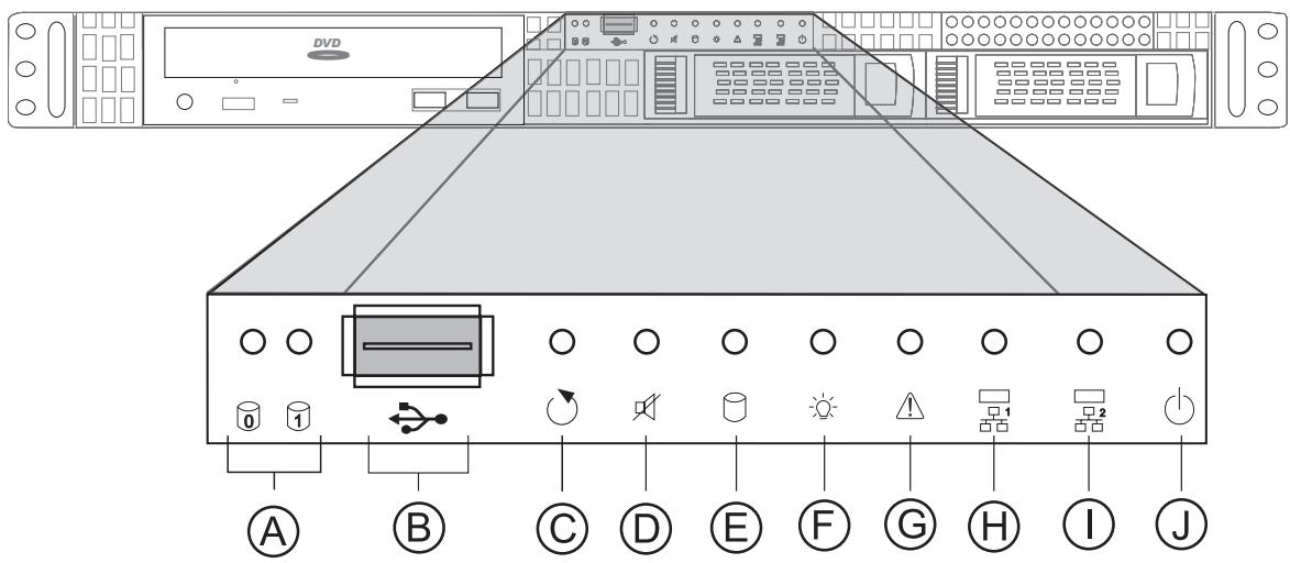
Figure 1. Front View
A. HDDTray Activity LEDs
F. Power LED
B. USB 2.0 Port
G. Failure LED
C. Reset Button
H. NIC Activity LED 1
D. Fan Alarm Mute Button
I. NIC Activity LED 2 (not used in this sytem)
E. System HDD Activity LED
J. Power Button
2 System Features
This chapter briefly describes the main features of the server system.
Table 1 summarizes the major features of the board.
Table 1. Feature Summary
| Feature | Description |
| Chassis Dimensions | 43.5 mm high |
| 430 mm wide | |
| 569 mm deep | |
| 17.0 kg max. chassis weight | |
| Processor | Supports Dual-Core Intel® Xeon® processor 3000 series and Quad-Core Intel® Xeon® processor 3200 series |
| Supports Intel® Extended Memory System 64 Technology (EM64T) | |
| Memory | Four DIMM sockets supporting stacked DDR2 667/800 MHz ECC or non-ECC unbuffered memory (up to 8 GB of total system memory) |
| Chipset | Intel® 3200 Chipset, consisting of: |
| • Intel® 3200/3210 Memory Controller Hub (MCH) | |
| • Intel® I/O Controller Hub (ICH9R) | |
| • Intel® 6702 PXH-V PCI-X Hub | |
| Peripheral Interfaces | Super I/O: Winbond 8374LF2 |
| External connections: | |
| • Stacked PS2 ports for keyboard and mouse | |
| • DB9 Serial A port | |
| • Two RJ45 NIC connectors for 10/100/1000 Mbps connections | |
| • Two USB 2.0 ports | |
| Internal connections: | |
| • One USB port header which supports two USB 2.0 ports | |
| • One DH10 Serial B header | |
| • Six SATA connectors (3 Gbit/s) with integrated RAID support | |
| • ATX-compliant 24-pin control panel header | |
| Video | On-board iBMC Server Engine with integrated video adapter and external 32MB video memory |
| LAN | • Intel® 10/100/1000 82566E Gigabit Ethernet Controller |
| • Intel® 10/100/1000 82541PI Gigabit Ethernet Controller | |
| Expansion Capabilities | • One x8 PCI Express connector on a full size riser card |
| Fans | Support for two system fans and one processor fan |
| System Management | Intel® System Management Software |
Connector and Header Locations
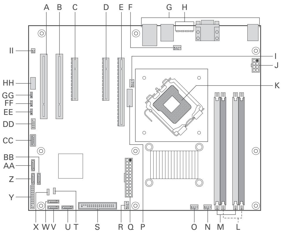
Figure 2 shows the approximate location of the major components on board.
Figure 2. Board Connector and Component Locations
Table 2. Board Connectors and Components
| Label | Description | Label | Description |
| A. | PCI (5V/32bit/33MHz) Slot 1 | S. | Floppy Connector |
| B. | PCI (5V/32bit/33MHz) Slot 2 | T. | HSBP |
| C. | PCI Express x8 | U. | SATA 0 |
| D. | PCI Express x8 | V. | SATA1 |
| E. | PCI Express x16 | W. | SATA 2 |
| F. | System Fan 1 Connector | X. | IPMB |
| G. | Back Panel Connectors | Y. | Front Panel Header |
| H. | Diagnostic LEDs | Z. | SATA 4 |
| I. | Processor Fan 1 Connector | AA. | SATA 5 |
| J. | 2x4 Aux Power Connector | BB. | SATA 3 |
| K. | Processor Socket | CC. | Internal USB |
| L. | Channel 2 DIMM Sockets | DD. | External USB |
| M. | Channel 1 DIMM Sockets | EE. | CMOS Clear Jumper |
| N. | System Fan 4 Connector | FF. | Password Clear Jumper |
| O. | System Fan 3 Connector | GG. | BIOS Recovery Jumper |
| P. | Battery | HH. | Serial Port |
| Q. | Main Power Connector | II. | Chassis Intrusion Header |
| R. | System Fan 2 Connector |
Configuration Jumpers
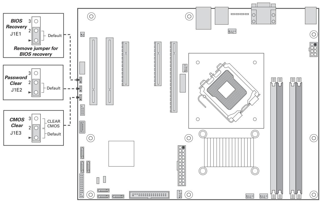
Figure 3 shows the location of the configuration jumpers.
Figure 3. Configuration Jumpers
Table 3. Configuration Jumpers
| Jumper Name | Function |
| BIOS Recovery | ·Pins 1-2: Normal operation ·Jumper removed: Recover from a corrupted BIOS. Bootable media with a valid BIOS ROM is required. |
| Password Clear | ·Pins 1-2: Normal operation, protected passwords ·Pins 2-3: Erase password: If these pins are jumpered for 5 to 10 seconds, the password will be cleared on the next server reset. These pins should not be jumpered for normal operation. NOTE The server does not need to be reset with the jumper on these pins for the password to be cleared. To reset the password using this jumper: Power down the server. Place the jumper on pins 2-3 for 5 to 10 seconds. Move the jumper back to pins 1-2. Power on the server. |
| CMOS Clear | ·Pins 1-2: Normal operation ·Pins 2-3: Erase CMOS: If these pins are jumpered for 5 to 10 seconds, the CMOS settings will be cleared on the next server reset. These pins should not be jumpered for normal operation. NOTE The server does not need to be reset with the jumper on these pins for the CMOS to be cleared. To clear the CMOS: Power down the server. Place the jumper on pins 2-3 for 5 to 10 seconds. Move the jumper back to pins 1-2. Power on the server. |
Back Panel Connectors
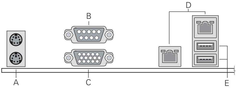
Figure 4. Back panel Connectors
Table 4. Back panel Connectors
| Label | Description | Label | Description |
| A. | Stacked PS2 Mouse/Keyboard Ports | D. | NIC 1/2 (10/100/1000 Mbps) |
| B. | Serial A | E. | USB1-2 |
| C. | Video |
The NIC LEDs at the right and left of the NIC provide the following information:
Table 5. NIC LEDs
| LED | LED State | Description |
| Right | Off | No network connection |
| Solid Green | Network connection in place | |
| Blinking Green | Transmit/receive activity | |
| Left | Off | 10 Mbps connection (if left LED is on or blinking) |
| Solid Green | 100 Mbps connection | |
| Solid Amber | 1000 Mbps connection |
Hardware Requirements
To avoid integration difficulties and possible board damage, your system must meet the requirements outlined below.
Processor
Supports Dual-Core Intel® Xeon® processor 3000 series and Quad-Core Intel® Xeon® processor 3200 series.
Memory
The Server Board provides four DIMM sockets across two banks. Bank 1 consists of DIMM sockets A1 and B1. Bank 2 consists of DIMM sockets A2 and B2. Minimum memory operation is a single 512MB DIMM in socket A1. This will provide single-channel interleave. For dual-channel interleave, two identical DIMMs are required in sockets A1 and B1.
To operate in dual-channel dynamic paging mode, the following conditions must be met:
- Populate two identical DIMMs in sockets DIMM A1 and DIMM B1.
- Populate four identical DIMMs in each socket location.
Note
The use of three DIMMs is not supported. Use DIMMs that are the same type and speed. Use of identical DIMMs is preferred.
DIMMs must meet the following requirements:
- Use only DIMMs with DDR2 DRAM technology.
- Use only DDR2-667 and DDR2-800 stacked DIMM modules.
3 Hardware Installations and Upgrades
Before You Begin
Before working with your server product, pay close attention to the "Safety Information" at the beginning of this manual.
Tools and Supplies Needed
Phillips (cross head) screwdriver (#1 bit and #2 bit)
- Needle nosed pliers
- Antistatic wrist strap and conductive foam pad (recommended)
Installing and Removing Memory
The silkscreen on the board for the DIMMs displays DIMM A1, DIMM A2, DIMM B1, DIMM B2 starting from the center of the board. DIMM A1 is the socket closest to the processor socket. See „Memory" for a discussion of the memory requirements and options.
Installing DIMMs
To install DIMMs, follow these steps:
- Observe the safety and ESD precautions in "Safety Information".
- Turn off all peripheral devices connected to the server. Turn off the server.
- Disconnect the AC power cord from the server.
- Remove the server's cover.
- Locate the DIMM sockets (see Figure 5).
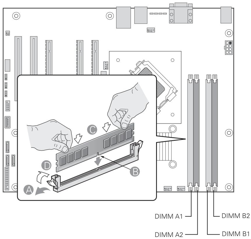
Figure 5. Installing DIMMs
- Make sure the clips at either end of the DIMM socket(s) are pushed outward to the open position (see letter "A" in Figure 5).
- Holding the DIMM by the edges, remove it from its anti-static package.
- Position the DIMM above the socket. Align the notch on the bottom edge of the DIMM with the key in the DIMM socket (see letter “B” in Figure 5).
- Insert the bottom edge of the DIMM into the socket (see letter "C" in Figure 5).
- When the DIMM is inserted, push down on the top edge of the DIMM until the retaining clips snap into place. Make sure the clips are firmly in place (see letter "D" in Figure 5).
- Replace the server's cover and reconnect the AC power cord.
Replacing the Backup Battery
The lithium battery on the server board powers the RTC for up to 10 years in the absence of power. When the battery starts to weaken, it loses voltage, and the server settings stored in CMOS RAM in the RTC (for example, the date and time) may be wrong. Contact your customer service representative or dealer for a list of approved devices.
WARNING
Danger of explosion if battery is incorrectly replaced. Replace only with the same or equivalent type recommended by the equipment manufacturer. Discard used batteries according to manufacturer's instructions.
WARNING
To replace the battery, follow these steps:
- Observe the safety and ESD precautions in "Safety Information".
- Turn off all peripheral devices connected to the server. Turn off the server.
- Disconnect the AC power cord from the server.
- Remove the server's cover and locate the battery.
- Lift the battery retention mechanism (see Figure 6).
- Remove the battery from its socket.
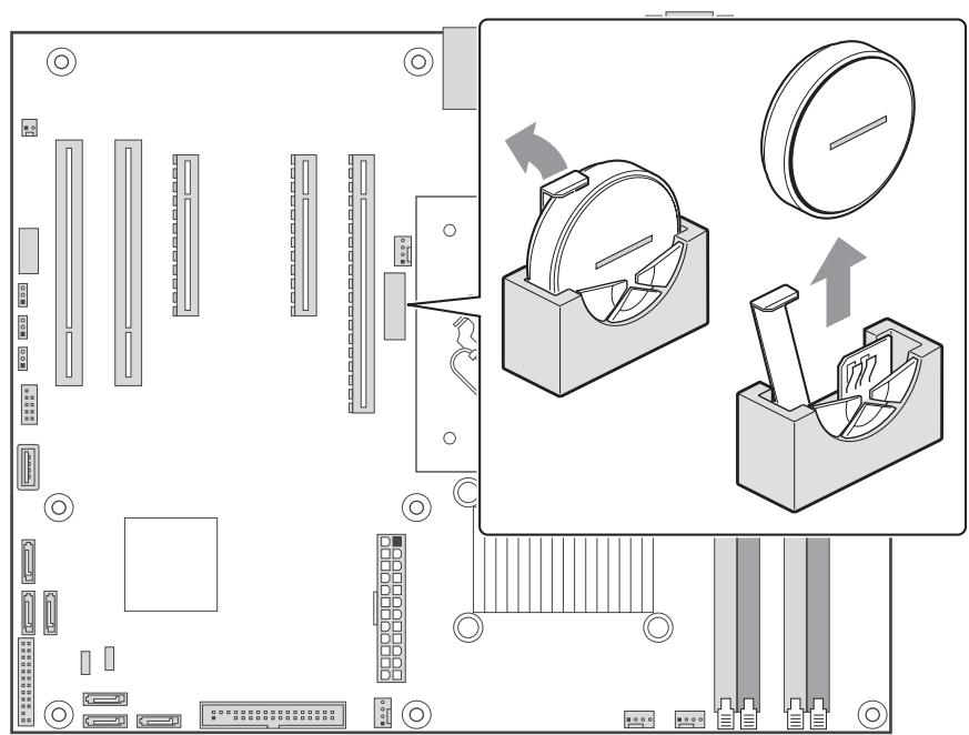
Figure 6. Removing the Battery
- Dispose of the battery according to local ordinance.
- Remove the new lithium battery from its package, and, being careful to observe the correct polarity, insert it in the battery socket.
- Close the chassis.
- Run Setup to restore the configuration settings to the RTC.
4 Server Utilities
Using the BIOS Setup Utility
This section describes the BIOS Setup Utility options, which is used to change server configuration defaults. You can run BIOS Setup with or without an operating system being present.
Starting Setup
You can enter and start BIOS Setup under several conditions:
- When you turn on the server, after POST completes the memory test
- When you have moved the CMOS jumper on the server board to the “Clear CMOS” position (enabled)
In the two conditions listed above, during the Power On Self Test (POST), you will see this prompt:
Press <F2> to enter SETUP
In a third condition, when CMOS/NVRAM has been corrupted, you will see other prompts but not the
Warning: CMOS checksum invalid
Warning: CMOS time and date not set
In this condition, the BIOS will load default values for CMOS and attempt to boot.
If You Cannot Access Setup
If you are not able to access BIOS Setup, you might need to clear the CMOS memory. For instructions on clearing the CMOS, see "Clearing the CMOS".
Setup Menus
Each BIOS Setup menu page contains a number of features. Except for those features that are provided only to display automatically configured information, each feature is associated with a value field that contains user-selectable parameters. These parameters can be changed if the user has adequate security rights. If a value cannot be changed for any reason, the feature's value field is inaccessible.
Table 6 describes the keyboard commands you can use in the BIOS Setup menus.
Table 6. Keyboard Commands
| Press | Description |
| <F1> | Help - Pressing F1 on any menu invokes the general Help window. |
| ← → | The left and right arrow keys are used to move between the major menu pages. The keys have no affect if a sub menu or pick list is displayed. |
| ↑ | Select Item up -The up arrow is used to select the previous value in a menu item's option list, or a value field pick list. Pressing the Enter key activates the selected item. |
| ↓ | Select Item down -The down arrow is used to select the next value in a menu item's option list, or a value field pick list. Pressing the Enter key activates the selected item. |
| F5/- | Change Value -The minus key or the F5 function key is used to change the value of the current item to the previous value. This key scrolls through the values in the associated pick list without displaying the full list. |
| F6/+ | Change Value -The plus key or the F6 function key is used to change the value of the current menu item to the next value. This key scrolls through the values in the associated pick list without displaying the full list. On 106-key Japanese keyboards, the plus key has a different scan code than the plus key on the other keyboard, but it has the same effect. |
| <Enter> | Execute Command -The Enter key is used to activate submenus when the selected feature is a sub menu, or to display a pick list if a selected feature has a value field, or to select a sub-field for multi-valued features like time and date. If a pick list is displayed, the Enter key will undo the pick list, and allow another selection in the parent menu. |
| <Esc> | Exit -The ESC key provides a mechanism for backing out of any field. This key will undo the pressing of the Enter key. When the ESC key is pressed while editing any field or selecting features of a menu, the parent menu is re-entered. When the ESC key is pressed in any sub menu, the parent menu is re-entered. When the ESC key is pressed in any major menu, the exit confirmation window is displayed and the user is asked whether changes can be discarded. |
| <F9> | Setup Defaults - Pressing F9 causes the following to appear: Setup Confirmation Load default configuration now? [Yes] [No] If "Yes" is selected and the Enter key is pressed, all Setup fields are set to their default values. If "No" is selected and the Enter key is pressed, or if the ESC key is pressed, the user is returned to where they were before F9 was pressed without affecting any existing field values. |
| <F10> | Save and Exit - Pressing F10 causes the following message to appear: Setup Confirmation Save Configuration changes and exit now? [Yes] [No] If "Yes" is selected and the Enter key is pressed, all changes are saved and Setup is exited. If "No" is selected and the Enter key is pressed, or the ESC key is pressed, the user is returned to where they were before F10 was pressed without affecting any existing values. |
Clearing the CMOS
If you are not able to access the BIOS setup screens, the CMOS Clear jumper will need to be used to reset the configuration RAM.
- Power down the system and disconnect the AC power.
- Open the server.
- Move the jumper from the normal operation position, at pins 1 and 2, to the CMOS Clear position, covering pins 2 and 3.
- Wait 5 to 10 seconds.
- Return the CMOS Clear jumper to the Normal location, covering pins 1 and 2.
- Close the server chassis.
- Reconnect the AC power and power up the system.
Configuring the System for embedded Serial ATA RAID
Configuring the BIOS
- Make sure you are having at least two SATA hard drives.
- Enter system BIOS Setup by pressing the <F2> key after the Power-On-Self-Test (POST) memory tests begin.
- Go to "Advanced" - "SATA Controller Configuration"; ensure "Configure SATA as" is set to "RAID". Post product launch an additional selection between LSI and Intel® RAID will be possible here. At launch the Intel® Matrix Storage Manager Option will be enabled by this setting.
- Save your settings by pressing
.
Creating Intel® Matrix Storage Technology RAID set
NOTE
This RAID is supported for Windows operating systems only.
- Upon re-boot you will see the Intel® Matrix Storage Manager Option ROM status message on the screen. Press CTRL-I to enter the RAID Option ROM user interface.
- In the User Interface menu, select option #1; Create RAID Volume. Enter a volume name, press
. The RAID Volume name must be in English alphanumeric ASCII characters. - Use the arrow keys to select the RAID level (0/1/5/10), press
. - Select the drives to be used in the RAID array (only if there are more than two drives available), press
. - Select the stripe size (only for RAID 0/5), and press
. - Enter the size of the volume (If you select less than the maximum volume size you can create a second RAID array on the remaining portion of your volume, not recommended), and press
. - Finally press
to confirm your selections. - Exit the Option ROM user interface by pressing <ESC> .
Creating LSI Technology RAID set
NOTE
This option will be implemented post product launch.
- Upon re-boot you will see the Embedded RAID Option ROM status message on the screen. Press CTRL-E to enter the RAID Option ROM user interface.
- In the Management Menu, select option #1: "Configure". Choose "Easy Configuration".
- Mark ready drives to be used in the RAID array using the space bar and press F10 to end selection.
- On the "Select Configurable Arrays" screen press
and . - Enter the properties of the new RAID: RAID Level (0/1/10), Size, Stripe Size. Accept the settings.
- Exit the Easy Configuration Screen using
and save the configuration. - Return to the Management Menu and Initialize the new RAID.
- Exit the Option ROM user interface by pressing <ESC> .
Loading the RAID Drivers
- Begin Microsoft® Windows® Setup by booting from the Microsoft® Windows® installation CD.
- At the beginning of Microsoft® Windows® Setup, press
to install a third-party SCSI or RAID driver. When prompted, insert the floppy with the RAID driver. Install the appropriate SATA RAID Controller driver, either "Intel(R) ICH9R SATA RAID Controller" for Intel® Matrix Storage Technology RAID set or "Intel Embedded Server RAID Technology" for LSI technology RAID set. - Finish the Microsoft® Windows® installation and install all necessary drivers.
- Install the monitoring software included with your motherboard or after downloading it from the Internet: LSI MegaIDESpy or Intel® Matrix Storage Manager depending on the RAID technology you chose previously. This will allow for local monitoring of the RAID configuration. Additionally errors will be entered to the local system log files.
5 Regulatory and Compliance Information
Product Regulatory Compliance
Product Safety Compliance
The server complies with the following safety requirements:
EN 60950 (European Union)
- CE - Low Voltage Directive (73/23/EEC) (European Union)
Product RoHS Compliance
Restriction of Hazardous Substances: This server system is compliant to European Directive 2002/95/EC (RoHS).
Product EMC Compliance
The server has been tested and verified to comply with the following electromagnetic compatibility (EMC) regulations:
EN 55022 (Class A) - Radiated & Conducted Emissions (European Union)
EN 55024 (Immunity) (European Union)
CE - EMC Directive (89/336/EEC) (European Union)
Product Regulatory Compliance Markings
This product is marked with the following Product Certification Markings:
Table 7. Product Certification Markings
| CE Mark | CE |
Electromagnetic Compatibility Notices
Europe (CE Declaration of Conformity)
This product has been tested in accordance too, and complies with the Low Voltage Directive (73/23/ EEC) and EMC Directive (89/336/EEC). The product has been marked with the CE Mark to illustrate its compliance.