PC BTX - PC MAXDATA - Free user manual and instructions
Find the device manual for free PC BTX MAXDATA in PDF.


User questions about PC BTX MAXDATA
0 question about this device. Answer the ones you know or ask your own.
Ask a new question about this device
Download the instructions for your PC in PDF format for free! Find your manual PC BTX - MAXDATA and take your electronic device back in hand. On this page are published all the documents necessary for the use of your device. PC BTX by MAXDATA.
USER MANUAL PC BTX MAXDATA
Technical Specifications 6
Note 7
User note 7
Laser (service note) 7
Use 8
Environmentally sound PC system 8
Device Durability 8
Take Back Guarantee 8
Recyclable Device Construction 8
Material Requirements for Plastic Cases and Case Parts 9
Material Requirements for Printed Circuit Boards 9
Marking of Plastic Materials. 9
Noise Emission 9
Batteries 9
Information on the return of electrical and electronic waste in EU countries. 10
Energy Consumption 11
Definition of the MAXDATA warranty 12
MAXDATA warranty period 12
Scope of the MAXDATA warranty. 12
Exclusions from the MAXDATA warranty. 13
MAXDATA restriction to liability 14
Governing law 14
Data Backup 15
Wireless LAN 16
Additional safety notes for units with wireless LAN 17
CE-labelling for units with wireless LAN 18
Restrictions 19
France 19
Italy 19
Netherlands 19
Radio frequencies for units with wireless LAN 20
Frequencies 20
Legal requirements - exception clauses 21
Before Getting Started 22
Before Initial Operation 23
Contents 23
Positioning the Computer 23
Temperature and humidity 23
Connecting the computer 23
Avoiding risk of stumbling 23
Data storage media 24
Avoid jarring 24
Allow for ventilation 24
The PC in Detail 25
Elements of the PC 25
Front Panel Components 25
Optional extras 26
The Rear View 27
Connecting Peripheral Devices 29
Connecting a Monitor 29
Connecting a Mouse 30
Connecting the Keyboard 30
Connecting a Printer 31
Connecting the Power Cable 32
Switching the PC On 33
Switching the System Off 34
The CMOS Battery 34
Components of the PC 35
The Floppy Disc Drive 35
Use and Care of Floppy Disks 35
The CD-ROM Drive 36
The Keyboard 37
Servicing / Maintenance / Cleaning 40
Midi / Micro Tower 40
Micro Desktop 40
Troubleshooting 41
Index 43
Introduction
Congratulations on your purchase of the MAXDATA personal computer! We are confident that it will meet your high expectations. This manual will familiarize you with your MAXDATA PC's components and features. We have taken all possible care to ensure that this manual contains correct, accurate information. However, we cannot assume liability for any possible errors. Please refer to your dealer for reporting errors or comments. We appreciate all feedback and are eager to incorporate any useful suggestions and improvements. All rights reserved. No part of this manual may be reproduced, processed or distributed in any form (print, photocopy, microfilm or any other process) or processed by an electronic system without prior written permission of MAXDATA. Other brand names may be registered trademarks and must be treated as such.
Copyright 2007 MAXDATA International GmbH, Marl
Technical Specifications
Your PC requires alternating current at 50 / 60Hz . To connect the device to the power supply, plug in the power cable. To disconnect it from the power supply, pull out the power cable. Utilize an easily accessible grounded outlet.
The input voltage is: 200 - 240V
Operating environment:
Temperature : 10°C - 35°C
Humidity : 30% - 70% relative humidity (non-condensing)
Dimensions: Width / mm Height / mm Depth / mm
Midi tower: 198 514 477
Micro tower: 198 405 477
Micro desktop: 402 106 375
Please refer to the box label for more detailed information on the system's specifications (motherboard, graphics, sound etc.).
Note
This device meets the EN 55022 and EN 61000-3-2 standards for interference emissions, the EN 55024 standard for interference, and the EN 60950 electrical safety standard. Any change made to this device without approval by the manufacturer voids any guarantee of meeting these standards. In order to assure EMC compliance (electromagnetic compatibility), please follow the corresponding guidelines in this manual.
User note
This device was carefully designed and tested to prevent radio interference. However, you should note the following for external data cables: If you need to replace any of the data cables specified by the manufacturer, be sure that the replacement cables have the same shielding specifications as the original cable to prevent interference. Always use shielded power lines and only use external devices that are CE certified.
No guarantee for meeting these standards can be maintained if you do not conform to the above guidelines.
Laser (service note)
Caution!
Laser radiation when the cover is open!
This laser radiation is contained in the CD drives. When dismantling and /or opening this drive, be careful:
not to look into the beam, not even with optical instruments
not to expose yourself to the beam
to avoid eyes or skin being exposed to direct or scattered beam.
Failure to observe these guidelines can in the worst case lead to permanent blindness. The built-in CD drives contain no user-serviceable or repairable parts. CD drives are to be repaired solely by the manufacturer. Laser products of laser classes 1 to 3B may be used in the product. When the housing is unopened the device meets the requirements of laser class 1. By opening the device, laser devices up to laser class 3B may be accessible. The built-in CD drives contain no user-serviceable or repairable parts. CD-ROM drives are to be repaired by authorized technicians.
Use
This product is not intended for medical, life saving or life sustaining usage.
Environmentally sound PC system
This system was constructed to be environmentally safe, which can be seen in its durability, enhancement possibilities and recyclability. For devices featuring the 'Blue Angel' environmental label, details regarding disposal, recycling, power consumption and noise emissions can be found on www.maxdata.com.
Device Durability
This PC is a modular system. The components used can be easily exchanged or removed. The devices have been built in such a way that the following enhancements are always possible:
- Processor upgrade
- Adding or replacing memory modules
- Adding, changing, enhancing or connecting further mass storage devices
Upgrading the graphics capabilities
Free slots for individual upgrading
Please consult the enclosed warranty documentation for the warranty conditions.
Take Back Guarantee
We offer a take back guarantee for all our products, if the device shows signs of normal use. Returned devices are re-used or scrapped in an environmentally safe way. You can return your device to your local dealer.
Recyclable Device Construction
This device conforms with the principals of VDI guideline 2243 on "Construction of recyclable technical products". This guideline in detail embodies:
- Avoid non detachable connections (e.g. gluing or welding) between different materials.
- Mechanical connections must be easily detachable;
- Avoid covered parts or composite materials;
The device must be easily dismantlable, also for a simple repair; - Reduction of the use of multiple materials.
- Reduction of the use of multiple plastics for case parts
- Nearly all plastic case parts are made from the same, recyclable material.
Material Requirements for Plastic Cases and Case Parts
- All plastics used for the case are manufactured without the use of dioxins and furans.
- An independent testing laboratory in Germany has tested and approved the characteristics of the plastics used.
Material Requirements for Printed Circuit Boards
- All our suppliers have ensured us that their circuit boards do not contain PCB (polybromite biphenyl), PBDE (polybromite diphenylether) or chlorinated paraffin.
Marking of Plastic Materials
- All plastic parts of this device are marked in accordance with ISO 11469. This ensures a problem free separation of the different materials when recycling.
Noise Emission
This PC meets the requirements for noise emissions according to EN 27779 and falls below the following values:
| Operation mode | Sound power level LW (dB(A)) (according to ISO 9296)) |
| Idle | < 48 |
| Drive operation | < 55 |
Batteries
This device does not contain batteries containing heavy metals. The lithium batteries used have an extremely long life span ( >10 years). Please consult the notes in the manual concerning servicing, replacement or disposal of the battery.
Information on the return of electrical and electronic waste in EU countries according to Directive 2002/96/EC, and its implementation in respective national regulations
a) Reason and Purpose of Separate Collection
Users of electrical and electronic equipment are required to dispose of used devices separately. Electrical and electronic equipment must not be disposed of together with unsorted municipal solid waste (domestic refuse), as it contains a range of dangerous elements that cause problems for waste management. Separate collection from regular municipal waste is a prerequisite for the special treatment and appropriate recycling of electrical and electronic waste. This is essential, as many components of electrical and electronic devices are damaging to the environment if they are not disposed of professionally. Disposing of the devices along with unsorted municipal waste can cause harmful substances to enter the waste flow. The consequence would be a considerable burden on the environment.
b) Significance the 'Crossed-Out Wheelie Bin'

The crossed-out wheelie bin is the symbol for separate collection.
Electrical and electronic equipment marked with this symbol must not be disposed of to-gether with municipal sorted waste (domestic refuse). Such items can be handed in free of charge at public collection points.
c) Reuse, Recycling and Recovery
Electrical and electronic waste contains valuable raw materials such as iron, aluminum and copper. These components must be treated selectively. A separate collection and a selective treatment are the basis for environmentally-friendly disposal and protection of human health.
According to the particular terms, manufacturers are obligated to assume the costs associated with disposing of these devices as well as other obligations. This is to promote the chief objectives of reuse and recycling. For this to be possible, consumers must dispose of used devices that are no longer needed at communal collection points. Actively using these return and collection systems contributes to the reuse, recycling and recovery of electrical and electronic equipment and protects the environment.
d) Weight
Information on the weight of the acquired product can be found on the item list as well as on the packaging.
Energy Consumption
Our PC systems have excellent energy saving features. The data on the type plate of the system applies to the maximum power consumption of the system, when the system is fully upgraded and the power supply is at 100% of its maximum output.
The devices can be separated from an external power source for at least 4 weeks, without losing any functionality.
You can specify the settings for the energy saving mode in the BIOS setup. Please refer to the user guide for your mainboard for information on the appropriate procedure.
The system only consumes no energy at all when the mains plug is disconnected.
Definition of the MAXDATA warranty
The MAXDATA warranty covers all failures resulting from defective components and manufacturing defects that occur within the product specific warranty period. The warranty period begins on the date of purchase (date of original customer invoice).
Please be aware that in order to maintain your warranty claim the product concerned has to be received by MAXDATA together with the serial number and a copy of the original customer invoice within the warranty period.
MAXDATA's obligation under the warranty is restricted to repairing or exchanging defective components.
Defective components removed during repair process become the property of MAXDATA. Components replaced within warranty coverage assume the remaining valid warranty period of the system.
Please refer to www.maxdata.com for the applicable MAXDATA warranty conditions.
MAXDATA warranty period
The type of standard warranty varies with the product and can be seen in detail in the description of warranty types and the warranty summary. It is possible to extend the standard warranty to include additional service packages.
Scope of the MAXDATA warranty
Scope of warranty for Belinea monitors
MAXDATA's obligation under the warranty is limited to failures resulting from defective components and manufacturing defects, defects in the CRT, panel and background lighting for electrical errors (please also refer to the term definition and liability restriction).
Scope of the warranty for MAXDATA Notebooks/PCs/FUSION Workstations/ Thin Clients/PLATINUM Servers
MAXDATA's obligation under the warranty is restricted to MAXDATA's choice of either the repair or replacement by similar or better components of parts determined to be defective.
Scope of warranty for peripheral devices
MAXDATA has no warranty obligation for these products; instead there are product-specific manufacturer warranties. The terms of these manufacturer warranties are at least 12 months, starting from the time MAXDATA delivers them to the specialist reseller. The manufacturer guarantees the presence of the features described in the product documentation and that the materials and processing will be free of defects for the stated period.
Scope of warranty for spare parts
MAXDATA has no warranty obligation for these products, but product-specific warranty obligations of the manufacturer. The terms of these manufacturer warranties can be asked for at the manufacturer concerned.
Exclusions from the MAXDATA warranty
The MAXDATA warranty does not cover damage of any kind that results from:
The use of peripheral devices
- Improper use/operating faults
Non-adherence to the user instructions
- Attempted repairs by the customer or third-parties without authorisation by MAXDATA
Defective maintenance by third parties
Device defects due to power failure, heat losses, missing EMC (electro-magnetic compatibility) cabling or similar reasons
- Accidents, storms, lightening, fire, water/other liquids, other natural catastrophes, theft, riots, plundering, the effects of war or other instances of acts of god
The use of third-party components
Non-authorised system changes
- BIOS versions/firmware updates/programmes to remove defects of all kinds (e.g. service packs, bug-fixes, hot-fixes)
- Resetting safety functions, deletion of passwords etc.
- Loss of customer-specific data or software from repair and installation processes
- Improper use of machine capacity or output
- Inappropriate customer operating environment
The MAXDATA warranty also does not cover the following:
- MAXDATA products from which the category plates, serial numbers, part numbers on the machine of machine parts have been removed or changed
- Decline in rechargeable battery capacity after the end of the 6 month warranty period
- The provision and installation of BIOS, driver or software updates/upgrades
-
The new installation of software/operating systems that are no longer able to run (e.g. because of the deletion of system-relevant files, incorrect system settings or self-copying programs, e.g. computer viruses)
-
Wear and tear on data storage media, LCD background lighting, CRTs on CRT monitors, picture tube burn-in or loss of brightness
- MAXDATA products for which the warranty seal has been broken by entities other than MAXDATA or those authorised by MAXDATA
- Breaks and scratches on TFT panels and CRT displays
- Damage through use of force and external impact respectively
- Spots on the panel caused by external impacts
Colour spots resulting from falls - Error class 2 pixel errors (please note the information on ISO 13406-2 on the website of the MAXDATA subsidiary concerned).
If the device received by MAXDATA demonstrates two defects and only one of these is covered by the MAXDATA warranty claim, the customer only has the right to repair for the damage to his device covered by the warranty.
In this case MAXDATA reserves the right to offer the customer several options on resolution in the form of a quotation and to charge the relevant processing costs.
This also applies to those devices for which upon receipt, it is found that they are not covered by the warranty. In these cases, MAXDATA reserves ownership of the exchange device provided and is entitled to demand its return.
MAXDATA reserves the right to charge costs incurred for unsuccessful attempts to collect a device that has been registered as defective from the customer.
If an exchange device is not provided in spite of a period having been set, MAXDATA is entitled to charge the net sales price as per the current price list plus the processing costs incurred.
The customer has the right to provide evidence for the existence of lower damages.
MAXDATA restriction to liability
MAXDATA expressly excludes customer claims that go beyond the warranty conditions if there is no obligation of liability imposed on MAXDATA by the laws of the country where the device was bought. This also applies in particular with regard to claims for damages as a result of default, damages for claims arising as a result of defects, loss of profit, transport damage that was not registered within a period of 6 days after receipt of the goods, loss of data or information through repair processes or damage resulting from interruption to operations.
Governing law
All rights and duties are subject to the law of the country in which the MAXDATA product was purchased. The Agreement on Contracts for the International Sale of Goods (CISG) is not applicable.
Data Backup
The responsibility for complete data backups, including of applications and operating system software remains exclusively with the customer. The data must be backed up before the warranty claim is made. MAXDATA excludes liability for any data or information lost for this reason during a warranty claim.
Please refer to www.maxdata.com for the applicable MAXDATA warranty conditions.
Wireless LAN
(wireless network - abbreviation = WLAN)
Your PC may contain a wireless LAN module (optional). This module allows you to set up a wireless-based network, and to connect to an existing wireless network. It works according to the IEEE802.11a+b+g standard.
WLAN technology allows users to set up wireless connections inside a local area (e.g. in a company or campus building, or in a public building such as an airport). WLANs can be used in temporary offices, in locations where it is not possible to set up extensive cable installations, or to extend an existing LAN so that users in different parts of a building can work at different times.
There are two different ways to operate a WLAN:
In fixed WLANs, wireless stations (devices with radio network cards or external modems) set up connections with wireless access points, which act as bridges between the stations and the existing network backbones.
In Peer-to-Peer (ad hoc) WLANs several users can set up a temporary network within a limited area such as a conference room, without using access points, and providing there is no need to use network resources.
In 1997 the IEEE confirmed the standard 802.11 for WLANs; this set a data transfer rate of from 1 to 2 Mbit/s (Megabits per second). Under 802.11a+b+g, the new governing standard, the maximum data transfer rate is 54 Mbit/s over a frequency band of 2.4 or 5 GHz (Gigahertz).
Additional safety notes for units with wireless LAN

If a wireless LAN module is integrated in your PC, it is essential that you observe the following safety information when using your PC:
- Switch off the PC when you are in an aircraft or while driving a car.
- If you are in a hospital, an operating room or close to an electronic medical system, switch off the wireless components in the PC! The radio waves which are transmitted could disrupt the working of the medical equipment.
- Keep the PC at least 20cm away from a heart pacemaker, otherwise there is a risk that the radio waves could disrupt the normal working of the pacemaker.
- The radio waves which are transmitted could give rise to interference noise in hearing aids.
- When its radio components are switched on, do not place the PC close to inflammable gases or in an environment which could be at risk of explosion (e.g. paint shop), since the radio waves which are transmitted could set of a fire or an explosion.
- The range of the wireless connection depends on the environmental and other ambient conditions.
- When transferring data over a wireless connection, unauthorized Third Parties can also receive the data.
MAXDATA International GmbH is not responsible for disruptions to radio or television reception which are caused by unauthorized alterations to this unit. MAXDATA also accepts no responsibility for the replacement or the exchange of connecting cables and units which were not specified by MAXDATA International GmbH. The user alone is responsible for the elimination of disruptions caused by this type of unauthorized alteration; he is also responsible for the replacement or the exchange of the units.
CE-labelling for units with wireless LAN
C∈
As delivered, this device complies with the requirements of the Guideline 1999/5/EG of the European Parliament and of the Council dated the 9. March 1999 concerning radio equipment and telecommunications facilities, and the mutual recognition of conformity.
This PC may be used in Belgium, Denmark, Germany, Finland, France, Greece, Great Britain, Ireland, Italy, Luxembourg, the Netherlands, Austria, Portugal, Sweden, Switzerland, Spain, Iceland, Liechtenstein and Norway.
Current information on any possible restrictions in its operation can be obtained from the appropriate authorities in each country. If your country is not included in the above list, then please contact the appropriate supervising authority, in order to check whether the use of this product is permitted in your country.
Belgium - www.bipt.be
Italy - www.agcom.it
Luxembourg - www.emat.lu/ILT
Netherlands - www.opta.nl
Austria - www.rtr.at
Portugal - www.urt.gov.pt
Sweden - www.pts.se
Switzerland - www.bakom.ch
Spain - www.cms.es
Iceland - www.pta.is
Liechtenstein - www.ak.li
Norway - www.npt.no
Restrictions
France
Restricted frequency range: In France, you may only use channels 10 to 11 (2457 MHz or 2462 MHz). It is forbidden to use the unit outside of enclosed areas.
Info: www.artelecom.fr
Italy
An official authorization is also required to use the unit in internal areas. For more detailed information about the necessary procedure to do this, please contact your provider. It is forbidden to use the unit outside of enclosed areas.
Info: www.agcom.it
Netherlands
A licence is required to use the unit in the open. For more detailed information about the procedure to be followed for this, please contact your provider.
Info: www.opta.nl
Radio frequencies for units with wireless LAN
The following information was correct at January 2002. You can obtain current information from the appropriate authorities in your country (e.g. www.regtp.de).
Frequencies
Radio network cards and adapters are designed in accordance with IEEE-Standard 802.11b+g for use in the ISM frequency band (Industrial, Scientific, Medical) between 2.4 and 2.4835 GHz. Because of the DSSS-procedure (Direct Sequence Spread Spectrum), each of the 11 usable radio channels takes up a width of 22MHz ; this means that up to three, independent channels are available (e.g. 3, 8 and 11). The following table lists the authorised channels in your country:
| Channel | MHz | Europe, R&TTE | France, R&TTE |
| 1 | 2412 | X | |
| 2 | 2417 | X | |
| 3 | 2422 | X | |
| 4 | 2427 | X | |
| 5 | 2432 | X | |
| 6 | 2437 | X | |
| 7 | 2442 | X | |
| 8 | 2447 | X | |
| 9 | 2452 | X | |
| 10 | 2457 | X | X |
| 11 | 2462 | X | X |
In addition, the integrated radio network card supports the standard 802.11a. For more information regarding 5 GHz band frequencies authorized in your country, please contact your respective appropriate authority.
Legal requirements - exception clauses
Exception Clauses For Units With Wireless LAN
The installation and use of an unit with Wireless LAN may only take place when in accordance with the instructions contained in the user documents. The user documents are included in the material supplied with the product. All alterations or modifications made to this unit which are not expressly authorised by the manufacturer may lead to cancellation of the right of the user to operate the unit. The manufacturer is not liable for radio disruptions during the reception of radio and television signals which are due to non-authorised alterations to the unit or to the exchange or connection of cables and accessories, where these are not in accordance with the recommendations of the manufacturer. It is the responsibility of the user to remove any interference which may arise as a result of any non-authorised alterations, or the addition or replacement of components. Neither the manufacturer nor his authorised dealer and wholesaler are liable for damages or breaches of legal regulations which result from an infringement of these guidelines.
Before Getting Started
This manual uses some symbols to facilitate the user's orientation and to highlight points of importance.
| Degree of danger | Damage to persons | Damage to property | Use with: |
| × | Immediate threat of danger; possible consequences: death or life-threatening injury. | ||
| × | Potentially dangerous situation; possible consequences: light or moderate injury. | ||
| × | Potentially harmful situation; possible consequences: the product or anything nearby may be damaged. | ||
| Useful information and recommendations that may make using your system easier. |
Contents
Before you begin the installation of your PC, make sure that you have all the parts. If anything is missing from the listed and illustrated packing list, please contact your dealer immediately.
- System unit
Keyboard (optional) - Mouse (optional)
Power cable - Operating system
Software - User's manual/Quick start guide (optional)
Depending on your system model, your PC may be different than the ones shown in this manual. When the differences are significant, the various options will be shown.
Positioning the Computer
Please take note of the following criteria for creating a practical and safe workplace when setting up your computer:
Temperature and humidity
The computer can be used anywhere the temperature is suitable for people. However, rooms with humidity over 70% , and dusty or dirty areas are not appropriate. In addition, do not expose the PC to temperatures over +35^ or under +10^ .
Make sure that you avoid temperature changes that could lead to condensation. If moisture has accumulated on the surface of your computer, wait until the moisture has dried completely (approximately one to two hours), before you switch the device on.
The operational reliability of a device that has been exposed to condensation cannot be guaranteed.
Connecting the computer
Make sure that the cables connecting the PC to peripheral devices are not under tension.
Avoiding risk of stumbling
Make sure that all power and connection cables are positioned so that they are not trip hazards.
Data storage media
When you save data to your PC's hard disk or to a floppy disk, it is stored as magnetic information on the medium. Make sure that data is not damaged by magnetic or electromagnetic fields.
Avoid jarring
Because the electronics in your computer can be damaged by jarring, no mechanical devices should be placed on the same surface as the PC. This is especially important for impact printers whose vibrations could damage the hard disk.
Allow for ventilation
There is a fan on the back of the PC that maintains the proper temperature inside the case. In order for it to function properly, the ventilation slots must not be blocked. Blocking them would cause the inner components to be damaged by high temperatures. That is why it is not appropriate to install the PC in a shelf unit or drawer.
Elements of the PC
All components necessary to operate your PC system are located on the front panel.
Front Panel Components
- The CD-ROM drive (optional).
- Floppy disk drive/ memory card slot (optional).
- The LED hard disk indicator display lights up when the hard disk is accessed.
- The power LED indicator display lights up when the computer is switched on.
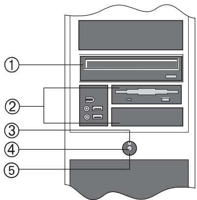
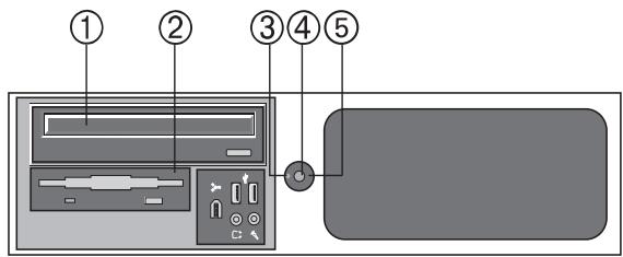
- The on/off button. This button has several functions:
a. Pressing this button switches the computer on.
b. If you briefly press the button while the computer is switched on, current operating systems shut the computer down.
c. Pressing the button for longer than four seconds switches the computer off.
All data that has not been saved will be lost.


The behavior of the on/off button and the LED operation display depends on the BIOS settings and the operating system. In case of queries refer to the user guide for your operating system (energy options) or to the mainboard handbook.
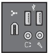
Optional extras
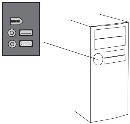
The following additional ports are available depending on the housing model and the system configuration. The following illustration shows which options may apply to your system.
Tower models
2 × USB
Loudspeaker
Microphone
FireWire (optional)
Desktop models
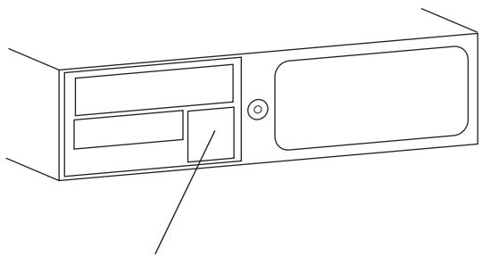
2 × USB
Loudspeaker
Microphone
FireWire (optional)
The Rear View
The ports on the rear side of the tower or desktop devices can vary in their detail depending on the system configuration. Because of the wide product range, the usual port options are shown here.
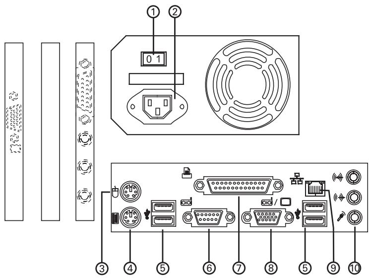
- The power switch. Here you can switch off the device when it will not be used for an extended period. If you want to avoid using any power whatever, you have to disconnect the mains plug.
- Mains connection socket - the power cable is inserted here.
- Mouse connection socket - the PS/2 mouse is connected here.
- Keyboard connection socket - the PS/2 keyboard is connected here.
- Rear USB connection sockets. USB peripheral equipment such as joysticks, mouse devices, scanners, printers or digital cameras are connected here.
- The serial COM1 interface - serial peripheral equipment such as a serial mouse, external modems, etc. can be connected here.
- Parallel LPT1 interface - this interface is a 25-pin socket. Here you can connect a printer.
-
15-pin graphics card port - the monitor is connected here. This socket may also be located on an expansion card (11) depending on the system configuration.
-
Network connection socket (optional - dependent on the system configuration). The built-in network adapter enables your computer to connect to the Internet via a network or DSL. The connection is made via an Ethernet network cable and RJ45 connectors. These are inserted on the back of the computer and into an available network hub or DSL socket.
- Sound module - Here you can connect loudspeakers (||), microphones (P) and an external sound source (||) such as a portable CD player or the output of a radio card. This module may also be located on an expansion card (12) depending on the system configuration. The analog (15-pin) connection for joysticks which may still be present here is increasingly being replaced by the USB port.
Connecting Peripheral Devices

Don't use force when connecting plugs - otherwise you may damage the plugs or connectors.

If the monitor is not able to process the frequencies from the graphics card, it could be destroyed!
Connecting a Monitor
Any monitor which complies with the VGA graphics standard can be connected to your PC. The connection socket for the monitor is located on the rear side of your PC and is marked with a monitor symbol.
If you use an older monitor, carefully compare the technical data of the monitor and the graphics card.
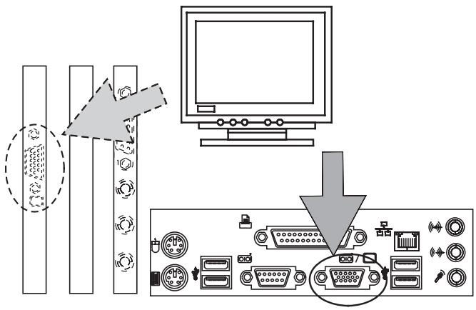
The computer and the monitor must be switched off when being connected, as otherwise the hardware may be damaged.
Connect the plug from your monitor to the 15-pin VGA connector of the graphics card of your PC.
Connect the monitor power cable to a grounded outlet.
Connecting a Mouse
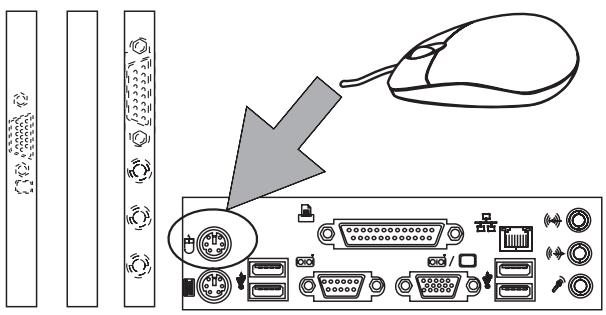
In addition to the PS/2 port there are USB ports and a serial mouse port (COM1) on the rear side of the computer.
Depending on the type of mouse plug you can attach the mouse to the PS/2 port, to the USB port or to the serial interface. It is recommended to connect the mouse directly or by means of an adapter to the PS/2 socket with the mouse symbol.
In this way you can use the USB and serial ports for other peripheral equipment.
Connecting the Keyboard
The PS/2 socket for connecting the keyboard is located on the rear side of the device. Connect the keyboard plug to the PC via the correspondingly marked socket. Always connect plugs to the PC carefully and without forcing.
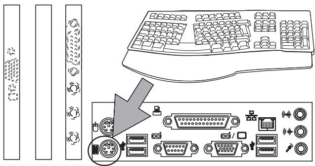
Connecting a Printer
Printers are normally distinguished by two different types of connection: parallel or USB interfaces. Many printers feature both options. It is recommended to connect the printer to the parallel interface. This retains your USB connection which you can use for a range of other devices.
When connecting the printer to the parallel port of the computer, both devices must be switched off.
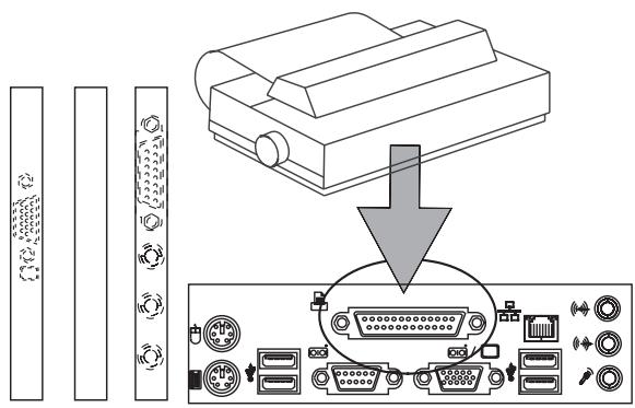
The printer is connected to your PC by a printer cable (not included). The parallel printer interface has 25 pins. It is located on the back of your computer and is marked accordingly.
Connect the printer cable to the parallel port of your PC (see figure 2-6). Plug the other end of the cable into the port of your printer.

If your printer has a USB plug, it is essential to read the operating instructions BEFORE connection. For example, you will often have to install the driver first. Note that before you use the printer for the first time, you must remove the transport protection and insert the ink or toner cartridge. See the user guide for the printer for further information. Frequently, you must also install the appropriate printer driver. You can find the necessary information in the printer user guides.
Connecting the Power Cable
The PC has a power adapter, which can be operated with 200 - 240 V AC. For Europe, it is always set at the factory to 200 - 240 V AC.
Ensure that the switch on the power adapter is set to "0".
Insert the power cable into the socket on the power adapter.
Connect the mains plug with a properly earthed shock-proof socket.

The power adapter contains no serviceable parts. Never open the power adapter -risk to life!
You could receive a deadly electric shock.
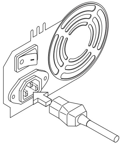
Switching the PC On
Before starting the computer, you should switch on the monitor, printer, modem etc. This ensures that the operating system recognizes the connected devices and integrates them accordingly.
Switch the power adapter switch from "0" to "1".
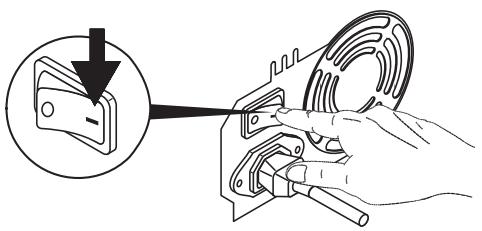
Turn on your PC by briefly pressing the ON/OFF button on the front.
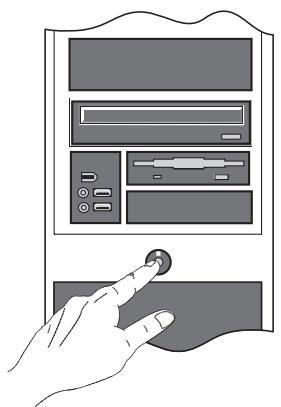
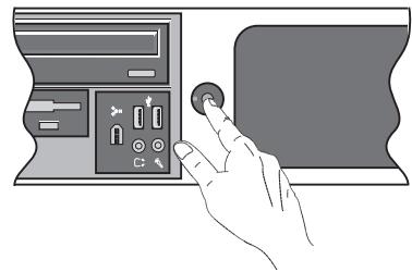
The PC carries out an internal self-test. If errors are detected during this test, these are displayed on the screen if possible. After successful completion of the PC self-test, the operating system (if installed) is started.
Switching the System Off
The switch off procedure of the system depends on its operating system.
Some operating systems shut down the PC completely and switch it off.
If your OS does not support this function, please press and hold the ON/OFF switch for longer than 4 seconds in order to switch the system off. In case you are not going to use the system for an extended period, please unplug the power cable at the back of your system.
The CMOS Battery

When changing the battery it must not be allowed to short circuit or be inserted with reversed polarity. A battery which is inserted with reversed polarity may explode or cause damage to the electronics on the motherboard.
Only use the battery type recommended by the manufacturer. You can purchase new batteries from your dealer.
There is a special type of memory on the motherboard of your PC which must not be erased, in contrast to the normal RAM. This memory is called CMOS RAM. It stores the internal configuration settings of BIOS, as well as important parameters for the system clock and calendar. In order to maintain the contents of CMOS RAM even when the PC is turned off, it is constantly supplied power from a battery.
Replace the CMOS battery as follows:
- Slide the safety latch to the side.
- Lift and pull the battery from the holder.
- Insert the new battery.
- Lock the battery in place.

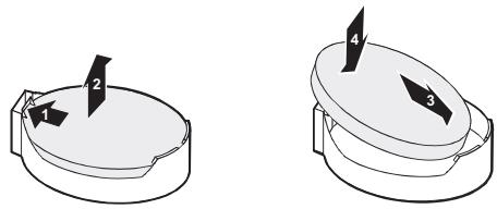

Don't dispose of batteries in a fire - they may explode. Batteries and rechargeable batteries do not belong in the household garbage. They are accepted free of charge by manufacturers, dealers or their representatives for recycling or disposal.
The Floppy Disc Drive
Fully insert a formatted disk into the disk drive until the eject button pops out. You can then access the data and/or write data to the disk.
To eject the disk from the disk drive, push the eject button.
Never eject a disk from the disk drive when the disk is being accessed.
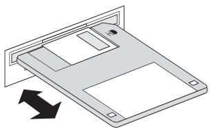

Data loss and damage to the disk
Use and Care of Floppy Disks
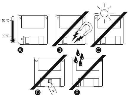
The following care should be given to floppy disks:
- Temperatures over +50^ and under +10^ have a negative impact on data security.
- Protect them from magnetic or electromagnetic influences.
- Do not place them in direct sunlight.
- Do not touch the magnetic disk.
- Do not expose the floppy disks to water (like rain etc.).
The CD-ROM Drive
Push the eject button on the CD-ROM drive as shown in the illustration while the computer is running. The compartment will slide open.
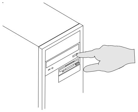
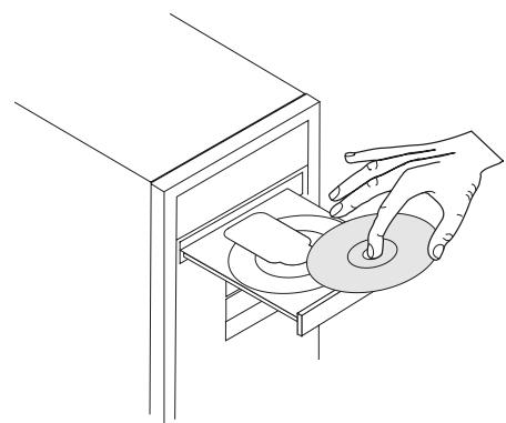
Place a CD into the depression of the tray with the printed side facing up. Try to avoid touching the underside of the CD with your fingers (see illustration).
To close the compartment, press the eject button of the CD-ROM drive once more.
Within a few seconds you will be able to access the data on the CD.
To remove the CD, repeat the above steps in reverse order.

Never use force to open the CD compartment. Should the compartment fail to open, shut down the computer and activate the manual emergency release. Please consult your CD-ROM drive's manual for more information.
Never place any objects on top of the tray.
Never place more than one CD in the compartment at a given time.

Built-in CD-ROM drives are Class 1 laser products. Do not open the device and do not look into the laser beam, even when using optical instruments.
Always keep the compartment closed when not in use in order to avoid excessive dust collection in the drive.
The Keyboard
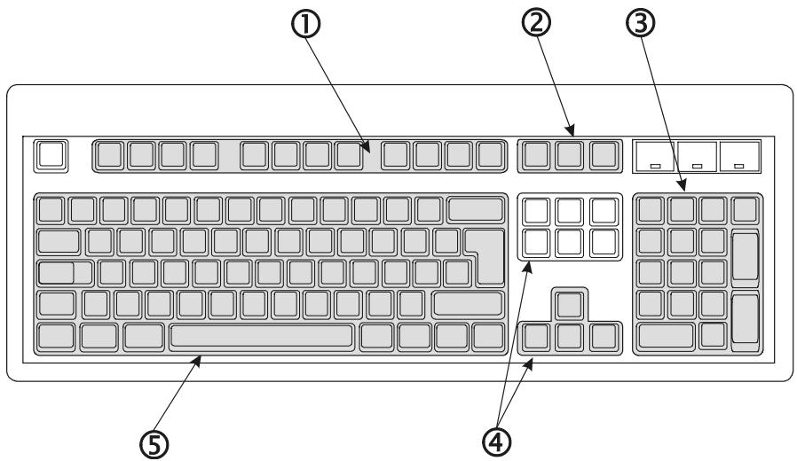
The keyboard is divided up into 5 logical units:
1. Function keys
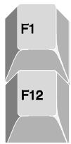
The 12 function keys are labeled F1 through F12.
The function keys have various functions depending on the software application.
The function keys can also be used in combination with the
2. Separate control keys
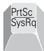
With the

The
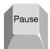
The
3. The numeric keypad and cursor block
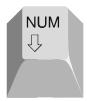
The
4. The control keys
The

When the
Use the

The
Use the
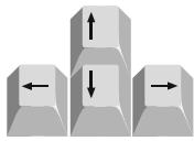
Use the arrow keys to move the cursor in the respective direction.
5. The typewriter keys
The typewriter keys consist of keys with numeric, alphanumeric and special characters. They are arranged like the keys on a standard typewriter.
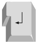
The
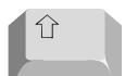
Use the
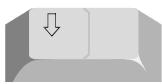
Press the

The
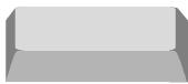
Press
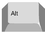
The
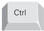
In most word processing applications, the
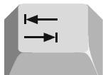
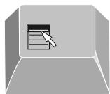
Press the special Microsoft® Windows® key to open the Start menu.

Use the
Servicing / Maintenance / Cleaning

Please ensure that the device is unplugged before commencing any cleaning, servicing or maintenance tasks.
The use of fans in the computer housing inevitably leads to dust settling inside the PC. A filter is placed at the entrance to the suction channel to prevent this. The air can enter, the dust remains outside. The advantages of using a filter are that the noise of the fan is dampened and the computer becomes quieter. The amount of dust which settles in the filter depends upon the computer's surroundings. If the filter becomes too clogged with dust, the device may overheat, resulting in diminished performance.
In order to replace the filter, proceed as follows:
Midi / MicroTower
Remove the front panel:
Grip one of the two openings on the underside of the front panel and pull the panel towards you. The filter is on the inside of the front panel, in front of the ventilation slots.
Micro Desktop
Remove the housing cover together with the front panel:
Open the housing cover using the rotating lock. The filter is on the inside of the front panel, in front of the ventilation slots.

Damaged components should only be replaced with MAXDATA original replacement parts.
Troubleshooting
In the following section you will find solutions for different kinds of problems. Please check the following list before you call technical support.
Screen is blank.
- Make sure your PC is not in standby mode - press any key to wake up.
- Make sure the monitor power switch is in the ON position.
Make sure the power cable is connected to a live outlet. - Check the contrast and brightness settings on your monitor.
The PC worked perfectly until new software was installed.
- Use a virus scanner to see if your PC is infected.
- Check the "readme" files for software incompatibility.
An error message appears on the monitor when accessing the floppy disk drive.
- You are using floppy disks that do not have the appropriate capacity.
- The floppy disk is defective.
Some keys do not work correctly.
- You have probably installed the wrong (or no) keyboard driver. Restart your operating system and make sure that the correct keyboard driver is indicated.
The printer won't print.
- Make sure that the cable between the PC and printer is correctly connected.
Make sure that your printer is online (see your printer manual).
The mouse is correctly connected, but isn't responding.
- Make sure that the mouse is correctly configured in your software. Refer to your mouse documentation.
If none of these suggestions help to fix the problem, please have the device repaired at your certified service partner.
Please refrain from attempting to repair the device on your own.
Index
A Alt 37, 39
B Battery 9,34 BIOS 11,13,25,34 Button 25,33
C
CD-ROM 7,25,36
CMOS . 34
COM1 . 27,30
Components . 5,8,12,13,24,25
Connecting . 30,31
Connection . 28,29
Ctrl . 37,39
D
Data storage media 14, 24
Dimensions .6
Disk .24, 25, 35, 41
DOS .37
E
Energy Consumption. 11
Environment .8,17
Ethernet .28
Expansion card .27,28
F
FireWire. 26
Function keys.. 37
G Graphics 8
Graphics card 27, 29
Guarantee 7, 8
H
Hard disk. 24, 25
Humidity .6,23
1 Ink 31
Input voltage .6
Interface 27,30,31
J Jarring 24 Joystick 27, 28
K
Key. 37,38,39
Keyboard. 23,27,30,37,41
Keypad . 38
L
Laser 7,36
LED 25,38,39
Liability 5,12,14,15
Loudspeaker 26,28
LPT1 27
M
Memory 34
Microphone 26,28
Modem 16,27,33
Monitor 12,27,29,33,41
Mouse 23,27,30,39,41
N Network. 16, 28
Numeric. 38, 39
O Operating system 11, 13, 15, 23, 25, 33, 34
P
Parallel 27,31
Peripheral 12, 13, 23, 27, 29, 30
Ports 27,30
Port options 27
Poweradapter 32
Power cable. 23, 29, 32, 41
Power supply 11
Power switch 27
Printer 27,31,33,41
PS/2 27,30
R
Radio. 16, 17, 18, 20, 21
RAM 34
Repair 7, 12, 13, 14
s
Screen 33, 37, 38
Self-test 33
Serial 27,30
Software 13, 15, 23, 37, 41
Sound 6,28
Standards 7
Storage 8
Switch 34, 41
Symbol 22, 29
T
Temperature 6,23,24,35
Test. 9, 33
Toner. 31
Transport 14,31
U
USB 28,30,31
V
VGA 29
W
Warranty 12, 13, 14, 15
Wireless LAN 16, 17, 18, 20, 21
Austria
MAXDATA Computer GmbH
Ignaz-Kock-Straße 9
A-1210 Wien
Phone: +431 (0) 27789-0
Benelux
MAXDATA Benelux B.V.
Bredaseweg 113-115
NL-4872 LA Etten-Leur
Phone: +31 (0) 76 5039250
France
MAXDATA S.A.R.L.
The MAXDATA Centre, Downmill Road
Bracknell, Berkshire, RG12 1QS, UK
Phone: +44 (0) 1344 788900