
LA800 PLUS - Thermal printer TALLYGENICOM - Free user manual and instructions
Find the device manual for free LA800 PLUS TALLYGENICOM in PDF.


| Product type | 24-pin dot matrix printer |
| Brand | TALLYGENICOM |
| Model | LA800 PLUS |
| Maximum print speed | Up to 1100 cps (characters per second) |
| Number of copies | Up to 7 original copies |
| Maximum resolution | 360 x 360 dpi (Letter Quality) |
| Supported paper types | Continuous paper (tractor) and sheet feed |
| Maximum paper width | 406 mm (front tractor option) |
| Interfaces | Parallel (Centronics), Serial (RS-232C), Ethernet 10/100Base-TX |
| Emulations | Epson ESC/P2, IBM XL24, DEC PPL2 |
| Buffer memory | Up to 128 KB |
| Power supply | 120/230 V AC, selectable |
| Monthly duty cycle | 40,000 to 50,000 pages per month |
| Main features | High-speed printing, automatic head gap adjustment, multi-copy management, built-in barcodes, macro commands, configuration menu |
| Maintenance and cleaning | Ribbon replacement, cleaning of the casing, interior, roller, and carriage shafts |
| Safety | Surge protection, replaceable fuse, paper end sensor |
| Spare parts and repairability | Ribbon cassette (ref. 060097), fuse, accessories: front tractor, pedestal, catch tray |
| General information | 157-page user manual available in PDF, multiple languages |
Frequently Asked Questions - LA800 PLUS TALLYGENICOM
User questions about LA800 PLUS TALLYGENICOM
0 question about this device. Answer the ones you know or ask your own.
Ask a new question about this device
Download the instructions for your Thermal printer in PDF format for free! Find your manual LA800 PLUS - TALLYGENICOM and take your electronic device back in hand. On this page are published all the documents necessary for the use of your device. LA800 PLUS by TALLYGENICOM.
USER MANUAL LA800 PLUS TALLYGENICOM
Printer at a glance 3
Printer in tractor mode 4
Printer in single-sheet mode 4
Paperway 5
Installation 6
Unpacking the printer 6
7
Checking the printer voltage 8
Connecting the printer 8
Switching on the printer 9
Inserting the ribbon cassette 10
Installing the ribbon cassette the first time 10
Changing the ribbon cassette 15
Printer drivers 20
Installing a printer driver in Windows 95/98/ME 20
Installing a printer driver in Windows 2000/NT 4.0/XP 21
Other operating systems 22
Changing printer settings 23
Form settings (Windows 2000/NT 4.0/XP) 23
Graphic options 24
Loading optional firmware 25
Troubleshooting 25
The control panel 26
The LC display 27
Online mode 28
Offline mode 28
Setup mode 29
30
Key functions when turning on the printer 31
Paper handling 32
Changing the paper path 32
Changing the paper type in the setup menu 33
Loading paper 34
Fanfold paper 34
Single sheets 36
Paper transport 38
Moving the paper to the tear position 39
Removing paper 40
Settings 41
Setting the tear position 41
Setting the first printing line (TOF) 42
Setting the print head gap 43
Selecting character density and font (temporarily) 44
The Menu 45
Programming via the control panel 45
Enabling access to menu mode 45
45
Menu configurations (Macros) 46
Menu handling 47
Save settings 47
Selecting the LC display language 48
Terminating Setup mode 49
Menu structure 50
Menu parameters 51
Printing out macro configurations (Print) 51
Loading menu configurations (Macro) 51
Reset to default values (Reset) 52
Quiet mode printing (Quiet) 52
Selectingfont (Font) 53
Setting line spacing (LPI) 54
Selecting start signal for escape sequence (ESCChar) 54
Selecting Protocol (emulation) 55
Bidirectional printing (PrintDir) 56
Settings for interfaces (I/O) 57
Serial interface (Serial) 57
Data transmission rate (Baud) 57
Data format (Format) 58
Buffer control (BuffCtrl) 59
Signal Processing (DTR) 59
Selecting interface (Interf.) 60
Interface buffer (Buffer) 60
Selecting interface timeout (Timeout) 61
Ethernet interface (ETH-INT) 62
Setting IP address (IP Addr) 62
Setting Gateway address (Gateway) 62
Setting Subnet mask (Subnet) 63
IP address administration (IP Get M) 64
Banner page (Banner) 64
Automatic carriage return (Auto-CR) 65
Automatic line feed (Auto-LF) 65
Menu lock (MenLock) 66
Language (Language) 67
Paper parameters (Paper) 67
Form length (Formlen) 68
First printing position (FormAdj) 69
Print head gap manually (Head) 70
View and tear position (TearView) 71
Line length (Width) 72
Barcode (Barcode) 72
Normal characters and barcode (Barmode) 73
Form feed mode (FFmode) 74
Setting and activating options (PapOpt) 75
Activation of tractors (AutoTra) 75
Automatic paper motion sensor (PMS) 76
Automatic gap adjustment (AGA) 77
Paper handling (Paphand) 77
Increasing the print head gap (Head up) 78
Paper width (Pagewid) 78
Left-hand area (Leftzon) 79
Right-hand area (Rightzo) 79
Bidirectional parallel interface (CX-bid) 80
Line wrap (Wrap) 80
Beep at paper end (Sound) 80
Setting for printing copy paper (HvyForm) 81
Automatic paper width detection (APW) 82
Automatic detection of the top paper margin (AED) 83
Setting the page margins (Margin) 84
Setting the top margin (Topmrg) 84
Setting the bottom margin (Botmrg) 85
Setting the left margin (Leftmrg) 85
Setting the DEC Mode (DECMode) 86
Horizontal spacing of characters (CPI) 86
Character set (CharSet) 87
User preference character set (UserID) 88
Printer ID (Prn.ID) 89
Deleting sequence or buffer (CAN Fkt.) 89
Disconnection on end of transmission (Discnct) 90
Initial Report (Report) 90
Automatic answerback (Answerbck) 91
Answerback on ENQ (Answer_ENQ) 91
Setting the IBM mode (IBMMode) 92
Horizontal spacing of characters (CPI) 92
IBM character set (IBM-Cset) 92
Code page (CodPage) 93
IBM Double Height (DbIHigh) 94
Horizontal pitch on Compress (IBMComp) 94
Slashed Zero (Sl.Zero) 95
Setting the EPSON Mode (EPSMode) 96
Horizontal spacing of characters (CPI) 96
EPSON character set (EPS-Cset) 96
Code Page (CodPage) 97
Slashed Zero (Sl.Zero) 98
Menu settings (example) 99
Advanced menu 100
Test functions 100
Printer self-test (Rolling ASCII) 101
Exiting Rolling ASCII test mode 102
Interface test (H-Dump) 103
Printout in Hex-Dump 103
Terminating Hex-Dump 104
Advanced settings 105
Deactivate single sheet feeder (Single) 106
Settings for paper with dark back (Pap.back) 106
Troubleshooting 107
General print problems 108
The display remains dark 108
The display is lit, but the printer does not print 108
Problems with the paper feed 109
Paper jam (fanfold paper) 109
Paper jam (single sheets) 110
Paper does not move to tear off position 110
Problems with the print quality 111
Print is too pale 111
Smudged print 111
Prints undefined characters 111
The first line is not completely printed out at the top 111
Dots within characters are missing 111
Error messages via the display 112
Additional display messages 115
Care and maintenance 116
Replacing the fuse 116
Cleaning the housing 117
Cleaning the interior 117
Cleaning the platen 118
Ribbon 118
Cleaning the upper friction 118
Carriage shafts 118
Specifications 119
Printer specifications 119
Interface specifications 123
Paper specifications 125
Available character sets and fonts 126
Emulations 131
General 131
Escape sequences 131
What are escape sequences? 131
How are escape sequences used? 131
Barcode 132
List of available barcodes 132
Interfaces 133
Parallel interface 134
Connector assignment 134
Serial interface V.24/RS232C 135
Connector assignment 135
Interface cable (serial interface) 136
Input signals 136
Output signals 136
Ethernet interface 137
Hardware 137
Supported operating systems 137
Supported protocols 137
Designation of IP address 137
Configuration 137
Status 137
Management 137
Setup 137
Interface-Adapter IF Adapter-Set RS232 (DB9M)/MMP 138
Protocols 139
Memory mode XON/XOFF 139
Memory mode Robust XON/XOFF 139
Configuring the serial interface of the PC 140
DOS mode 140
Windows 95/98/ME 140
Windows 2000/NT 4.0/XP 140
Physical printer port in Ethernet with TCP/IP 141
Example of a printer connected to a computer in
an Ethernet 141
Example of several devices in an Ethernet 141
Options and accessories 142
Options 142
Tractor 2, front 142
Printer pedestal 142
Paper output tray 142
Cable cover 142
Interface modules 142
Accessories 143
Ribbon cassette 143
Programming manuals 143
Index 144
Introduction
Printer features
Your printer is a high speed and rugged design for easy use and heavy duty operation. It is designed for service-free PC, network and mini system operations.
At top speeds of 1100 and 900 cps the LA800+ and LA650+ keep pace with the bustling, demanding world where printing is time sensitive and critical. Engineered for printing under adverse conditions, these devices produce multi-part invoices, shipping documents or bar code labels at a rate of 40,000 to 50,000 pages per month.
The printer handles up to 7-part forms with no skewing or jamming; it automatically adjusts for different forms thickness. The straight paper path is easy to access, for reliable forms handling.
The LA800+/LA650+ optionally is configured with an optional tractor (front). A straight paper path on the front tractors results in jam-free operation and flawless 24-wire impressions on up to 7-part forms. Both models offer fully automated gap adjustment, paper parking, loading, etc.
With extensive connectivity alternatives and popular emulations, the printer is ideal for a variety of industrial or business applications.
Symbols used
Important information is highlighted in this manual by two symbols.

CAUTION highlights information which must be observed in order to prevent injuries to the user and damage to the printer.

NOTE highlights general or additional information about a specific topic.
About this manual
The user guide contains a detailed description of the printer, its characteristic features and additional information.
Chapter 1 Printer at a glance lists all the parts of the printer.
Chapter 2 Installation contains start-up instructions and points to note.
- Chapter 3 Inserting the ribbon cassette provides step-by-step instructions for changing the ribbon cassette.
Chapter 4 Printer drivers provides step-by-step instructions for installing the printer driver.
Chapter 5 The control panel explains how to control printer operations.
Chapter 6 Paper handling tells you how to set the paper type and how to load, transport and move the paper to the tear-off position.
Chapter 7 Settings tells you how to adjust the basic settings such as font, character density, print head distance, print line height and tear-off position.
Chapter 8 The Menu contains all the information necessary for controlling the printer via the control panel.
Chapter 9 Advanced menu describes the possible test settings and other technical adjustments of the printer.
Chapter 10 Troubleshooting provides instructions for rectifying faults which do not require the intervention of qualified personnel.
Chapter 11 Care and maintenance provides information on the upkeep of the printer.
Appendix A Specifications informs you about the technical specifications of your printer and the paper which should be used.
- Appendix B Available character sets and fonts lists the available character sets.
Appendix C Emulations deals with programming via the interface.
Appendix D Interfaces explains the interfaces.
- Appendix E Options and accessories contains information about options and accessories you can purchase for your printer.
1 Printer at a glance

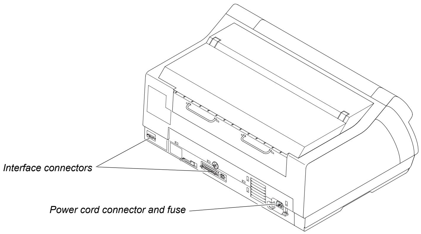
Printer in tractor mode
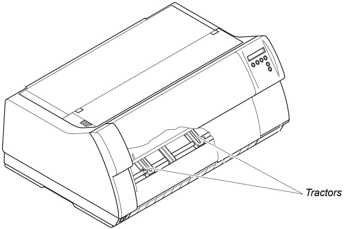
Printer in single-sheet mode
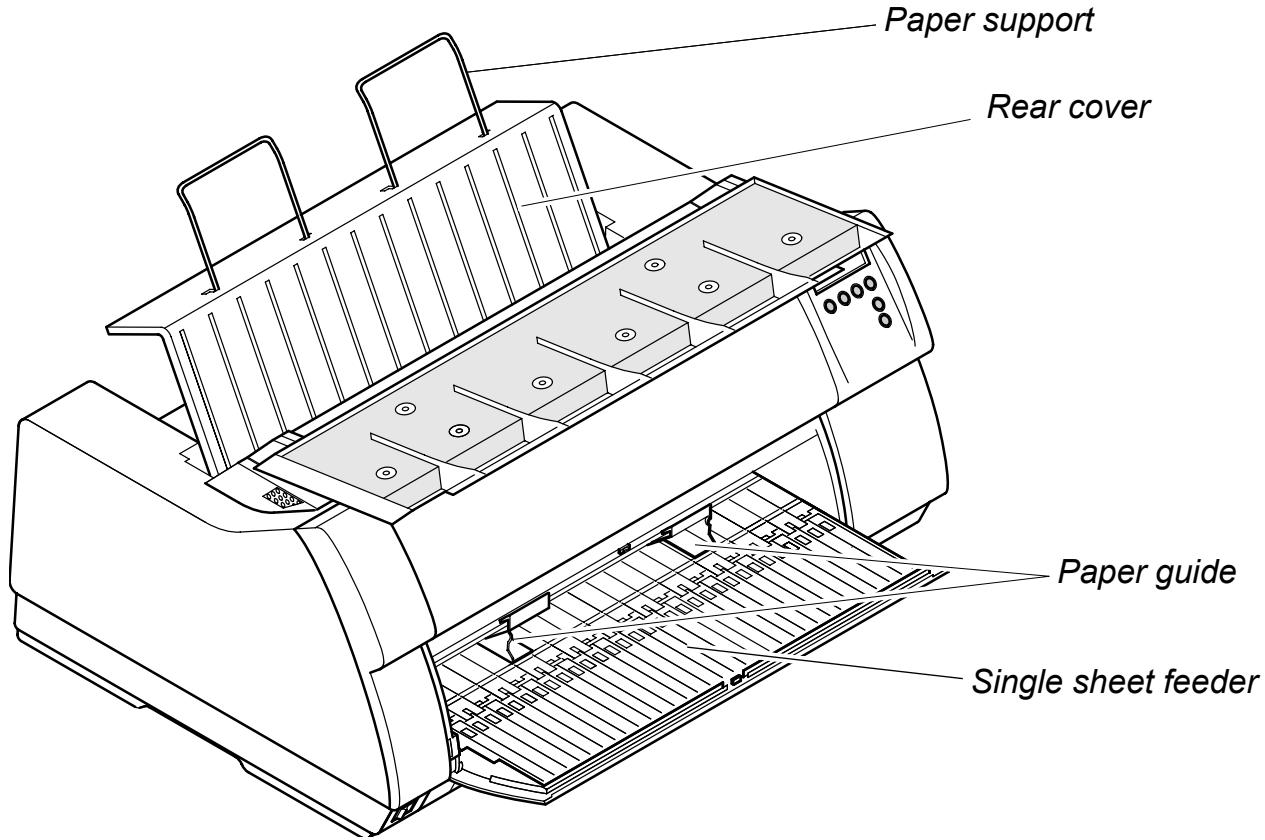
Paperway
Standard printer: Tractor 1 Single sheet*
Option: Tractor 2
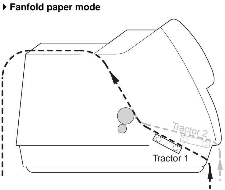
Single sheet mode*
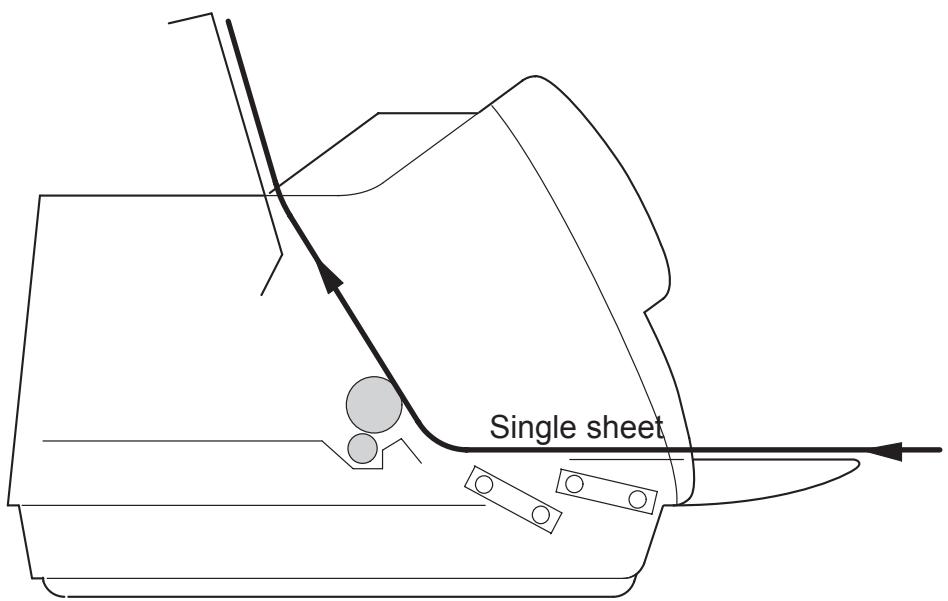
- Not available on some models.
2 Installation
Unpacking the printer
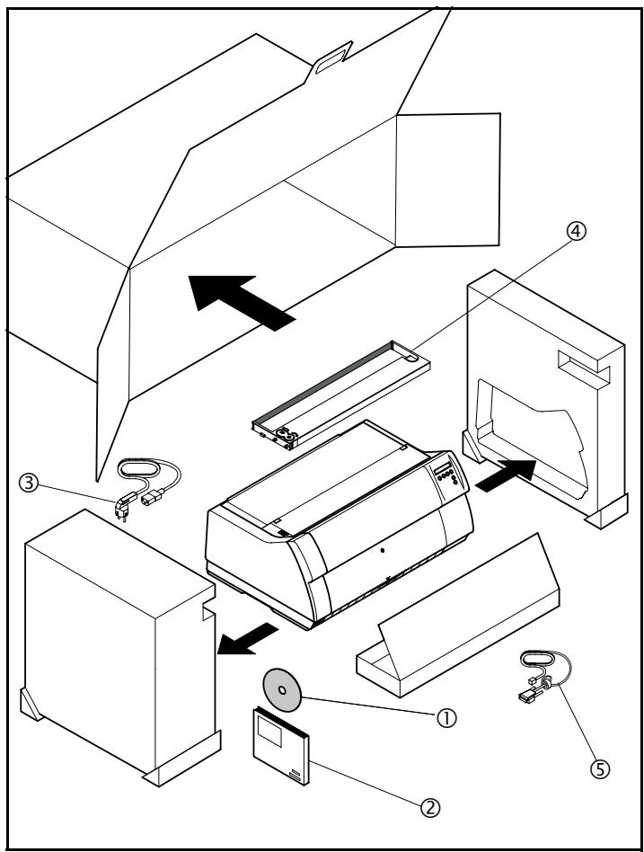
Place your printer on a solid surface (see Placing your printer, page 7).
Make sure that the "Up" symbols point in the correct direction.
Open the packaging, take out the accessory cassette and unpack it. Pull the printer out of the cardboard box towards you and remove the remaining packaging material.
Check the printer for any visible transport damage and completeness. Apart from this CD-ROM (①) the Quick start guide (②), the power cable (③), the ribbon (④) and the MMJ interface adapter (⑤) should be included.
If you find any transport damage or if any accessories are missing, please contact your dealer.
Placing your printer
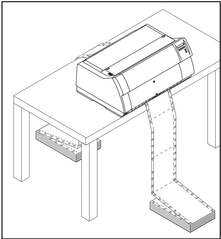
Place the printer on a solid, flat, surface, ensuring that the printer is positioned in such a way that it can not topple, and that there is easy access to the control panel and paper input devices. Also ensure that there is sufficient space for the printed output.
If you expect that frequent forward and reverse feeds will occur, you should place the printer as shown in the figure, if possible.

The power supply cable may be damaged if the paper edges constantly chafe the insulating sheath. The user must always ensure that there is sufficient distance between the power supply cable and the paper.
When selecting the printer location, observe the following additional instructions:

Never place the printer in the vicinity of inflammable gas or explosive substances.
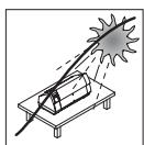
Do not expose the printer to direct sunlight. If you cannot avoid placing the printer near a window, protect it from the sunlight with a curtain.
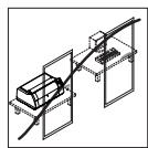
When connecting the computer with the printer, make sure not to exceed the permitted cable length (see Interface specifications, page 123).
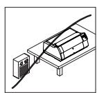
Ensure sufficient distance between the printer and any heating radiators.
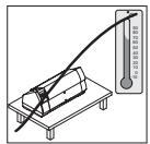
Avoid exposing the printer to extreme temperature or air humidity fluctuations. Above all take care to avoid the influence of dust.
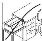
It is recommended to install the printer in a place which is acoustically isolated from the workplace because of the noise it may produce.
Checking the printer voltage
Make sure that the device has been set to the correct voltage (e.g. 120V in the USA, 230V in Europe). To do this, check the type plate above the power inlet at the back of the printer. Contact your dealer if the setting is incorrect.

Never switch on the printer if the voltage setting is incorrect, since this may result in severe damage.
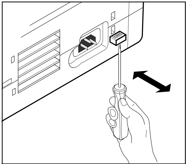
If the setting is incorrect, set the colored switch at the rear of the printer to the correct position, using a pointed object (e.g. screwdriver, ball pen or tweezers).

Make sure that the printer is switched off before setting the correct voltage; otherwise severe damage may be caused.
Connecting the printer
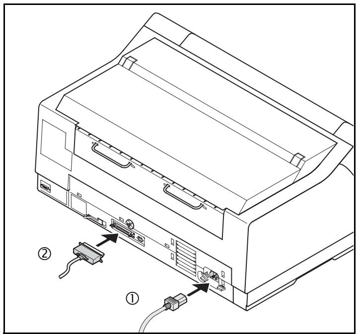
Connect the power cable ① to the power inlet of the printer. Connect the power cable plug to a mains socket.
Make sure that the printer and the computer are switched off and connect the data cable ② between the printer and the computer.

The printer by default is provided with a parallel, an Ethernet and a serial interface. For further information about the inter-faces, refer to the section Interfaces (page 133).
Switching on the printer
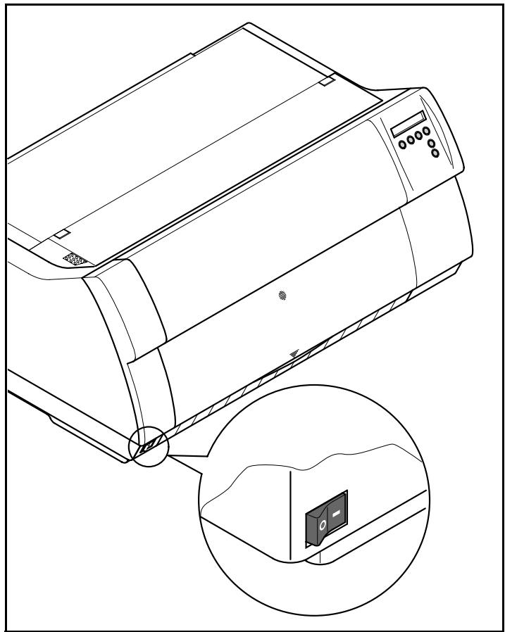
The power switch for switching on the printer is located at the bottom left at the front of the printer when viewed from the front.
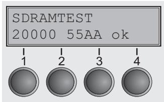
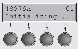
After switching on, the printer passes through a memory test during the initialization phase. In the display appears temporary the message "SDRAMTESTXXXXXX Ok".
If the memory test is successful finished, the firmware number appears in the display.
After finishing the initialization the printer switches to online mode (see Online mode, page 28).

Inserting the ribbon cassette
Installing the ribbon cassette the first time
When delivered, no ribbon cassette is installed. When you switch on the printer the first time, the printers display shows the message:
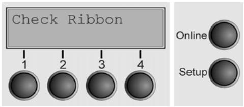
Now insert the supplied ribbon cassette.

During the process of initialization after powering on, the printer checks if a ribbon cassette is installed. It also checks during the execution of a print job the operativeness of the ribbon cassette. These functions mandatory require the use of the manufacturers original ribbon cassettes (see Accessories, page 143). If other ribbon cassettes were used, the message Check Ribbon appears in the display, it is impossible to print.
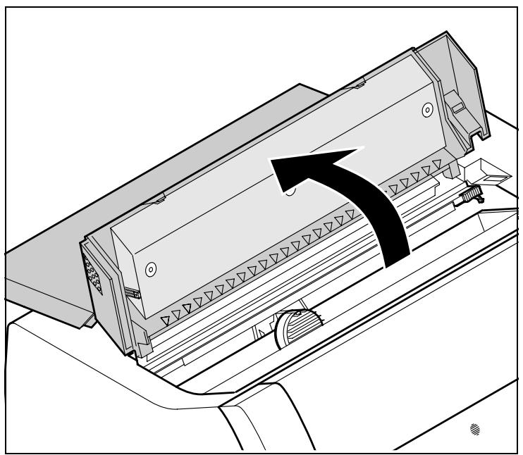

Before opening the cover, make sure that the printer is switched on so that it can execute automatic preparations for ribbon changing (widening the print head gap).
Open the printer top cover.
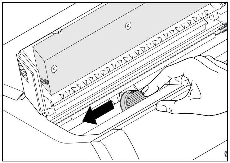
Cautiously slide the print head carriage to the left stop (viewed from the printer front).
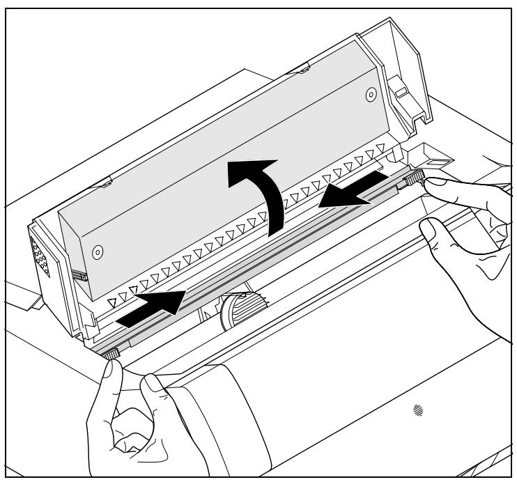
Move the coloured friction tabs to the left and right (direction of the arrows) as shown in the figure and raise the friction mechanism.
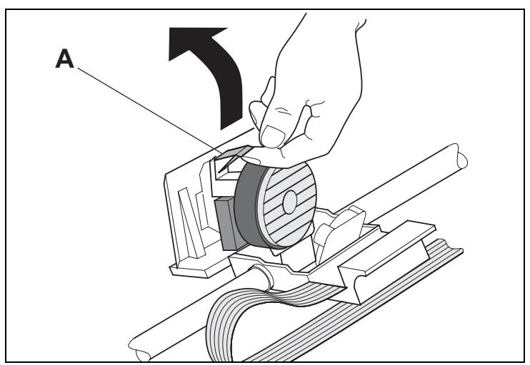
Raise the coloured insertion tongue A.
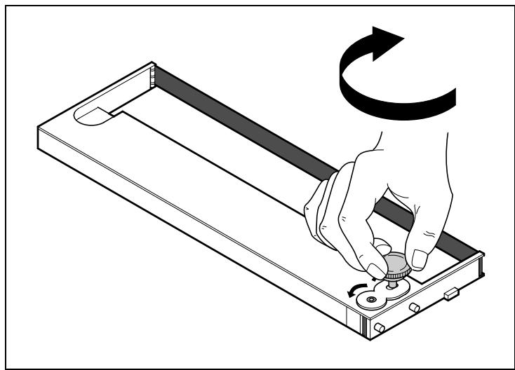
Insert the coloured ribbon tension knob into the right-hand front location of the new ribbon cassette. Turn the knob in the direction of the arrow in order to take up slack of the ribbon.
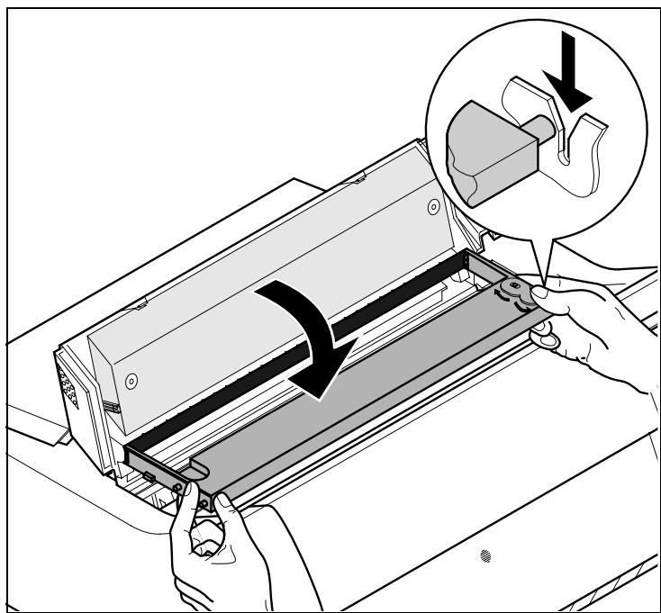
Slightly tilt the ribbon cassette forwards and thread in the ribbon between the coloured insertion tongue and the ribbon support (transparent plastic plate).
Align and insert the cassette into the guides on the left and right, then press down until it clicks into place.
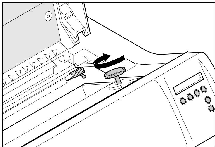
Insert the coloured tension knob into one of the two locations.
Turn the tension knob to take up slack in the ribbon until it is seated correctly at the bottom in the ribbon support.
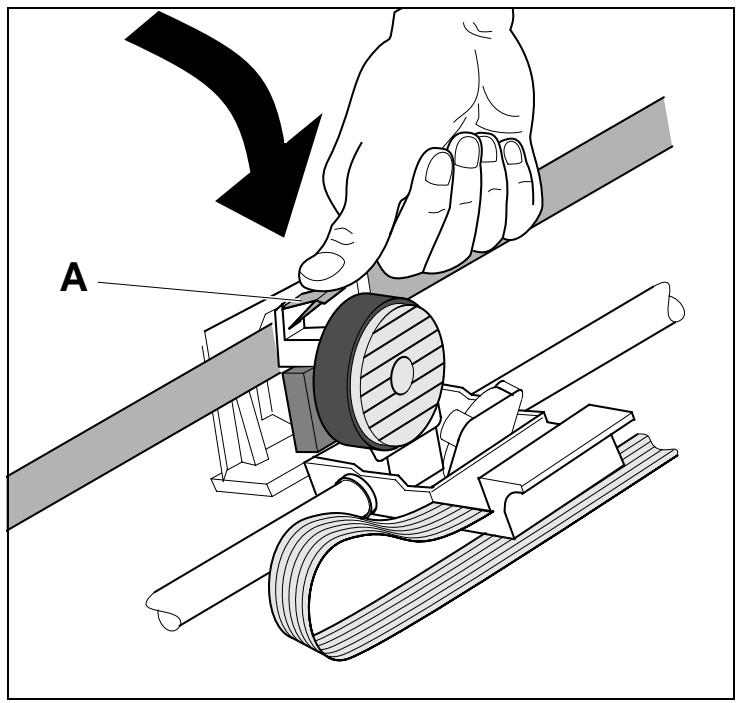
Press down the coloured insertion tongue A.
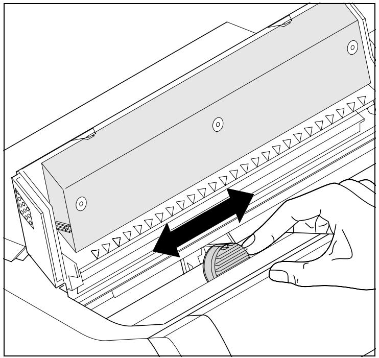
Move the print head carriage back and forth several times. If the ribbon is correctly seated, there must be no perceptible resistance.

The ribbon should be transported during the travel from left to right. If this is not the case, you should check that the ribbon cassette is correctly inserted on the right.
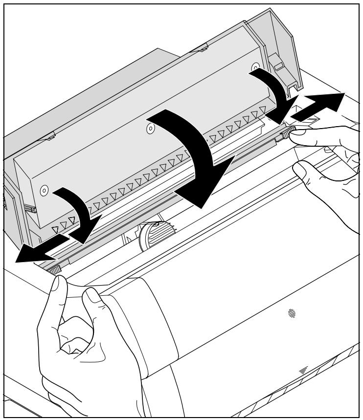
Press the friction mechanism down until it clicks into place.
Close the top cover.
Changing the ribbon cassette

During the process of initialization after powering on, the printer checks if a ribbon cassette is installed. It also checks during the execution of a print job the operativeness of the ribbon cassette. These functions mandatory require the use of the manufacturers original ribbon cassettes (see Accessories, page 143). If other ribbon cassettes were used, the message Check Ribbon appears in the display, it is impossible to print.
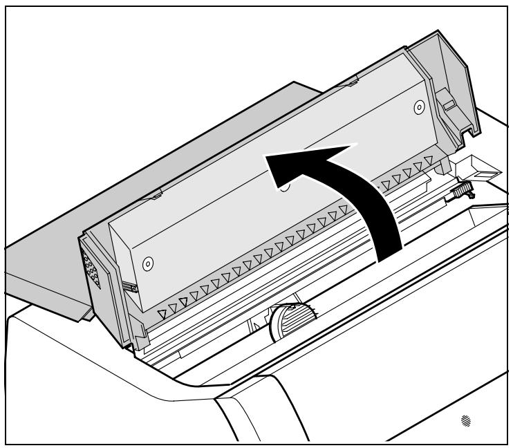

Before opening the cover, make sure that the printer is switched on so that it can execute automatic preparations for ribbon changing (widening the print head gap).
Move the paper to the park position.
Open the printer top cover.
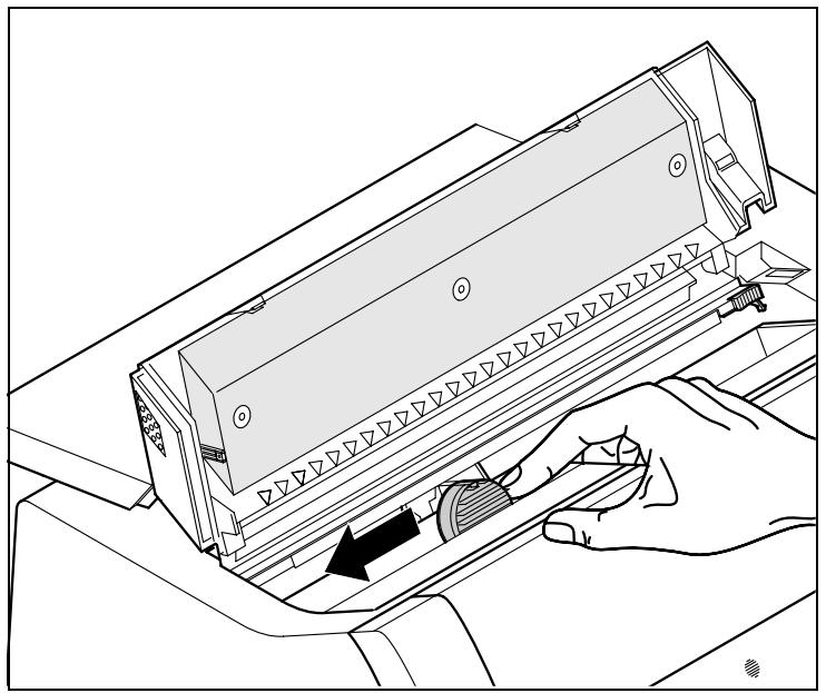
Cautiously slide the print head carriage to the left stop (viewed from the printer front).
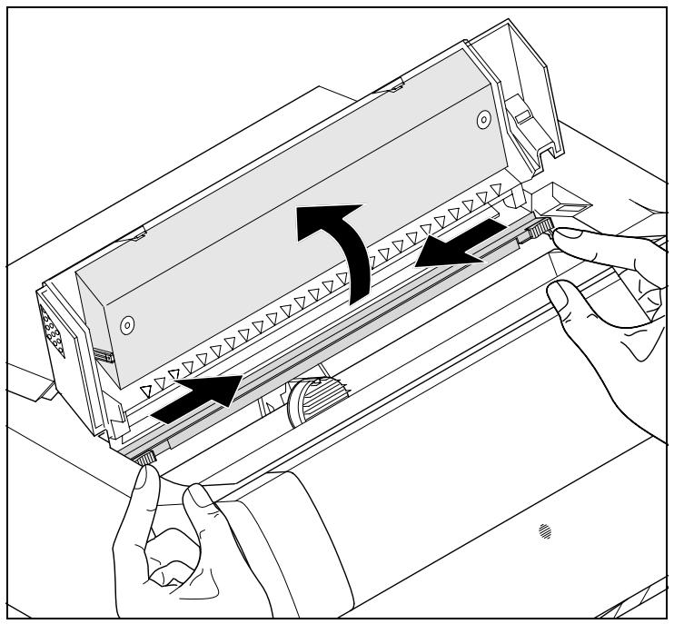
Move the coloured friction tabs to the left and right (direction of the arrows) as shown in the figure and raise the friction mechanism.
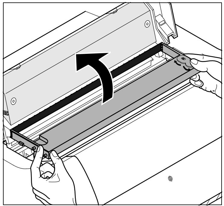
Remove the used cassette.
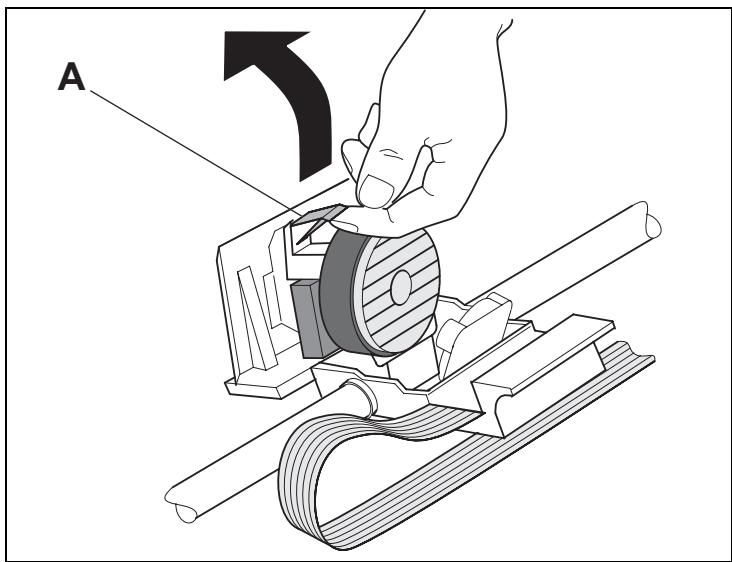
Raise the coloured insertion tongue A.
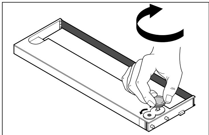
Insert the coloured ribbon tension knob into the right-hand front location of the new ribbon cassette. Turn the knob in the direction of the arrow in order to take up slack of the ribbon.
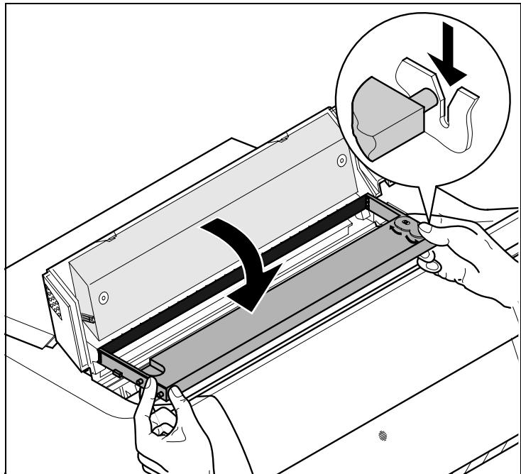
Slightly tilt the ribbon cassette forwards and thread in the ribbon between the coloured insertion tongue and the ribbon support (transparent plastic plate).
Align and insert the cassette into the guides on the left and right, then press down until it clicks into place.
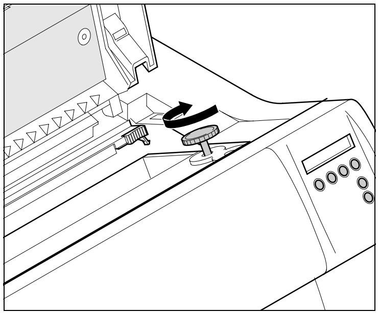
Insert the coloured tension knob into one of the two locations.
Turn the tension knob to take up slack in the ribbon until it is seated correctly at the bottom in the ribbon support.
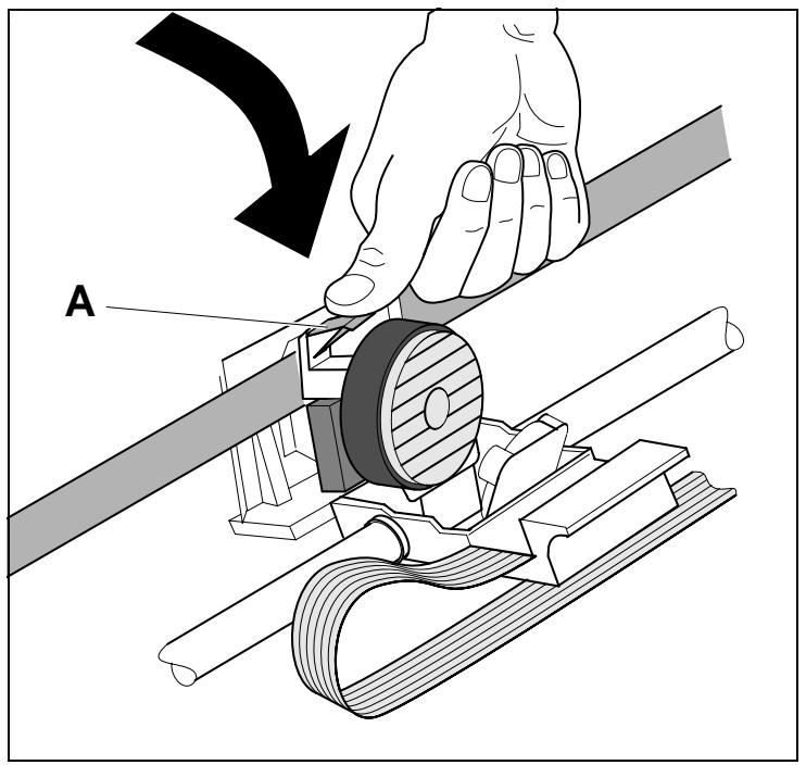
Press down the coloured insertion tongue A.
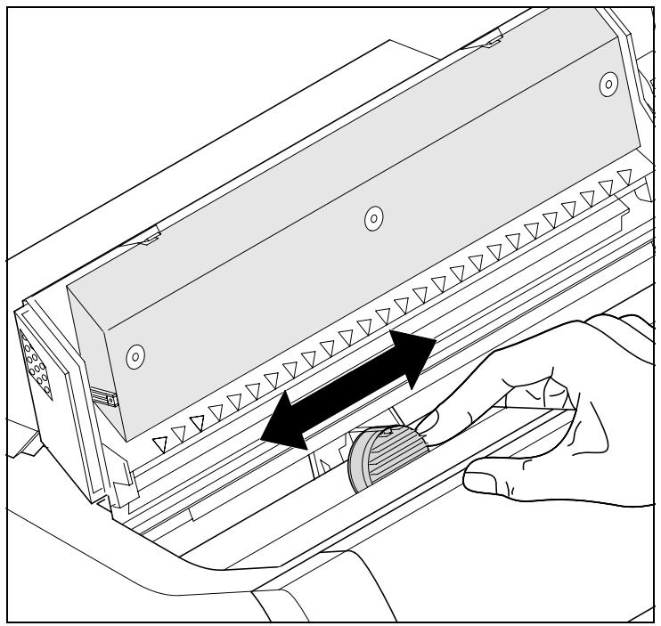
Move the print head carriage back and forth several times. If the ribbon is correctly seated, there must be no perceptible resistance.

The ribbon should be transported during the travel from left to right. If this is not the case, you should check that the ribbon cassette is correctly inserted on the right.
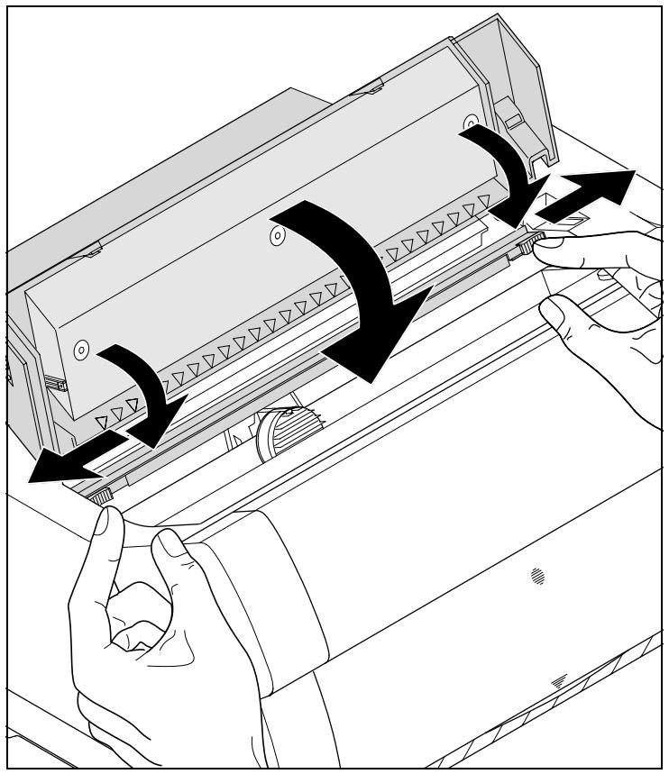
Press the friction mechanism down until it clicks into place.
Close the top cover.
4
Printer drivers
You need to install a printer driver so that the printer can process the data from your application programs.
An original driver offers the best conditions for optimal printing results. All available printer drivers can be found on the CD-ROM enclosed with the printer, as well as on our Internet site, from which you can also download updated versions as necessary.
Installing a printer driver in Windows 95/98/ME
To install the printer driver, proceed as follows.
1 Insert the supplied online CD-ROM in the CD-ROM drive.
2 Click on the Start button in the Windows taskbar.
3 Move the mouse to Settings and click on Printer to open the printer folder.
4 Click on New Printer.
5 Click on Next In the Printer Installation Wizard.
6 Specify whether you want to operate the printer as a Local Printer or Network Printer by clicking on the relevant option, then press Next.

For instructions on installing the printer as a network printer, please consult the documentation supplied with your network operating system and/or printer server, or contact the network administrator.
7 Click on Disk, then on Browse.
8 Select the CD-ROM drive and open the directory n:\english\drivers\

The printer driver is also available in German, French, Italian and Spanish language. If you want to install a printer driver in one of these languages open the respective directory.
9 Open the folder of your printer's operating system, select the file oemsetup.inf and click on OK.
10 Select the printer type. Click on OK, then on Next.
11 Select the port to which your printer is connected, then click on Next.
12 If required, edit the name of the default printer and specify whether you wish to use the printer as a default printer by clicking on the relevant option. Then click on Next.
13 Specify whether you wish to print out a test page (recommended) by selecting the relevant option and click on Finish. The printer driver will now be installed.
Installing a printer driver in Windows 2000/NT 4.0/XP
The online CD-ROM contains printer drivers for the most common Windows applications. To install the printer driver, proceed as follows.
1 Insert the supplied online CD-ROM in the CD-ROM drive.
2 Click on the Start button in the Windows taskbar.
3 Click on Printers and Faxes to open the printer folder.
4 Click on File and Add Printer in the menu bar.
5 Click on Next In the Printer Installation Wizard.
6 Specify whether you want to operate the printer as a Local Printer or Network Printer by clicking on the relevant option, then press Next.
For instructions on installing the printer as a network printer, please consult the documentation supplied with your network operating system and/or printer server, or contact the network administrator.
To install a network printer, you will need Administrator rights.
If you are using the printer locally, you can continue installing the driver in one of two possible ways:
- Manual installation of printer driver: in this case, continue with Step 7.
Automatic installation of printer driver via Plug & Play function: in this case, continue with Step 12 once the printer installation wizard has determined the printer, port and printer name.
Then click on Next.
7 Select the port to which your printer is connected, then click on Next.
8 Click on Data Carrier, then click on Browse.
9 Select the CD-ROM drive and open the directory n:\english\drivers\
10 Open the folder of your printer's operating system, select the file oemsetup.inf or printer.inf (Windows NT 4) and click on OK.
Other operating systems
11 Select the printer type. Click on OK, then on Next.
12 If required, edit the name of the default printer and specify whether you wish to use the printer as a default printer by clicking on the relevant option. Then click on Next.
13 If you are using the printer as a network printer, you have the option of sharing it with other network users. In this case you must enter an access name which will be displayed to the other network users. Then click on Next.
14 Specify whether you wish to print out a test page (recommended) by selecting the relevant option and click on Finish. The printer driver will now be installed.
The printer can also be used with other operating systems such as Linux or Unix. In this case, set the printer to the Epson emulation or IBM emulation for which default drivers are available in most operating systems.
Changing printer settings
You can make permanent changes to the printer settings using the control panel of the printer (see The Menu, page 45). Various printer settings can also be entered in the operating system of your PC, however.
1 Click on the Start button in the Windows taskbar.
2 Windows 95/98/ME: move the mouse to Settings and click on Printers to open the printer folder.
Windows 2000/NT 4.0/XP: click on Printers and Faxes to open the printer folder.
3 Move the mouse pointer to the appropriate printer symbol, press the right mouse key and click on Properties.
Details of the settings available in this window can be found in the Windows documentation or help pages.

Settings entered in the printer driver via Windows have priority over settings entered via the printer menu. It is therefore possible that the former may overwrite the latter.
Form settings (Windows 2000/NT 4.0/XP)
In contrast to Windows versions 95/98/ME, in which forms are defined in the printer driver itself, Windows versions 2000/NT 4.0/XP have a central facility for managing form properties and assign one paper feed only.
If you want to set up a form not included in the Windows default settings, proceed as follows.

You will need Administrator rights to define new forms.
1 Click on the Start button in the Windows taskbar.
2 Click on Printers and Faxes to open the printer folder.
3 In the menu bar, click on File and Server Properties.
4 In the window Printer Server Properties, click on Form if necessary.
5 Either select an existing form from the Forms list or activate the option New Form.
6 Enter a form name and the desired values.
7 Click on Save to save the new form.
You can now assign this form to the paper feeds of your printer (see Changing printer settings).

The form cannot be assigned if its dimensions exceed the permissible paper sizes of the specified paper feed.
Graphic options
You can select different print qualities via the Windows printer drivers (see table). This selection will affect the printing speed: the higher the print quality, the lower the speed (see Printer specifications, page 119).
To set the desired print quality, proceed as follows.
1 Click on the Start button in the Windows taskbar.
2 Windows 95/98/ME/2000: move the mouse to Settings and click on Printers to open the printer folder.
Windows NT 4.0/XP: Click on Printers and Faxes to open the printer folder.
3 Move the mouse pointer to the printer symbol, click on the right mouse key and click on Properties.
4 Windows 95/98/ME: Click on Graphics.
Windows 2000: Click on Printer Properties, then click on Advanced.
Windows NT 4.0/XP: Click on Printer Settings, then click on Advanced.
5 Windows 95/98/ME: Highlight the required setting in the list next to Resolution.
Windows 2000/NT 4.0/XP: Highlight the required setting in the list next to Print Quality.
6 Confirm your selection by clicking on OK.
| Print quality | Resolution |
| High Speed Quality | 90 x 60 dpi |
| Data Print Quality | 180 x 90 dpi |
| Copy Print Quality | 180 x 180 dpi |
| Near Letter Quality | 360 x 180 dpi |
| Letter Quality | 360 x 360 dpi |
Loading optional firmware

To load new firmware, proceed as follows.
The most current version of the firmware can be downloaded from our internet page.
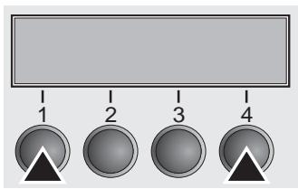
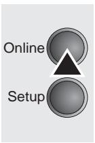
1 Switch off the printer. Connect your DOS PC (LPT1:) to the parallel port on the printer.
2 Press keys 1, 4 and Online. Hold the keys pressed.
3 Switch on your printer.
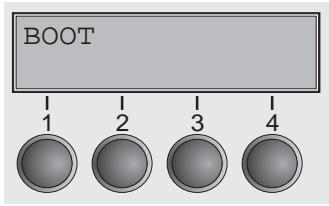
The printer is ready for the download when BOOT appears on its display.
4 In Windows open the MS-DOS window.
5 Copy the file, e.g. DOWNLOAD.FDF, to your printer: COPY /B X:\path\DOWNLOAD.FDF PRN (X:\path stands for the drive and the directory in which the file is located.)

A progress indicator (bar) and DOWNLOAD FIRMWARE appears on the display during the download; alternatively, an error message is displayed:
PRG = Firmware
GEN = Character set or font (character generator)
P + G = Firmware and character set
BOO = Firmware, character set and boot block
The number of the currently transferred data block (frame) is displayed in addition in the top line of the display on the right.
DOWNLOAD OK and BOOTAREA SKIPPED is displayed briefly when the procedure has been completed successfully. The printer then runs through its initialisation routine, after which it is ready for use. Repeated separate loading of firmware and character generators is possible.
Troubleshooting
It is necessary to repeat the entire procedure if an error occurs during the download. This is indicated by a corresponding message on the display. It may be that not all fault messages can be shown on the display. In this case, the operating system of your PC displays an error message such as "Write error on device".
5 The control panel
The control panel keys are used for controlling your work with the printer. The control panel is located on the front right side of your printer and consists of a two-line LC display and six keys.
The functions of the keys depend on the printer's current mode (status). There are four basic modes.
- The Online mode (display message: Ready) is the printer's normal operating mode. Data from your computer can be received and printed.
In the Offline mode (display message: Pause) the link between printer and computer is interrupted, i.e. no data can be received and printed.
In the Setup mode you can either select the printer menu or carry out the so-called quick-switch function. The quick-switch option was included so that you can change the most important parameters (for example adjustments, character density, font, paper path, adjustments i.e. head gap) directly without having to enter them via the menu. The settings for the parameters character density and font are lost when the printer is switched off. They can be selected permanently in the menu mode of the printer. - In the Menu mode further printer settings (line spacing, size of the interface buffer etc.) can be altered and saved permanently.
The LC display
The LC display tells you all the important printer settings and informs you which functions are currently assigned to which keys.
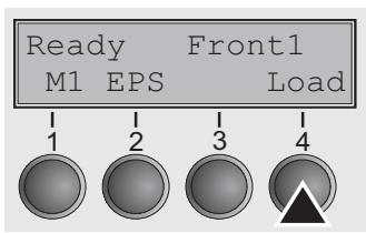
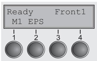
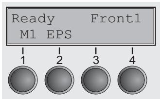
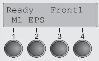
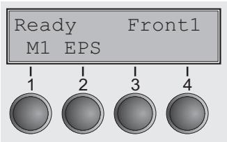
The upper line informs you that the printer is either in online or offline mode (in the example below the printer is in the Online mode), and the selected paperpath (below: Front1 = tractor mode).
Example:
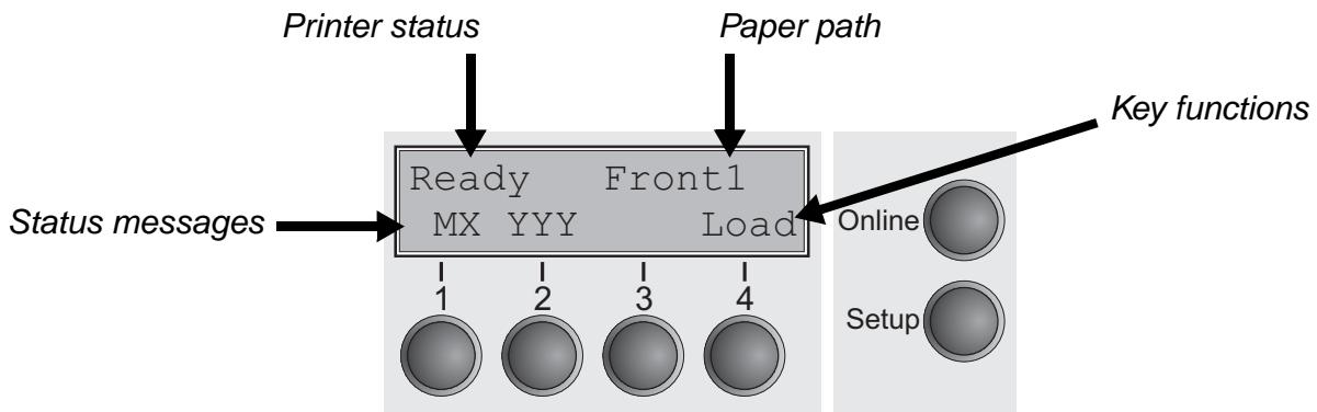
The second line informs you which functions are currently assigned to which keys. The word or symbol directly above a key tells you the current function of the key.
In our example, key 1 (Back) serves to activate the previous parameter group, while keys 2 (Font) and 3 (CPI) open the menus for editing the settings for fonts and character density. Key 4 (Next) takes you to the next parameter group.
Example:

Online mode
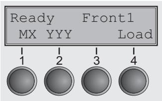
After switching on, the printer is automatically set to online mode. Only in this mode can it receive data from the computer.
- MX (a message only; X = 1 to 4): Shows the selected menu (Macro); for further information refer to Loading menu configurations (Macro) (page 51).
- YYY (a message only; YYY = EPS, IBM, DEC): Shows the active emulation of the active interface (parallel or serial); for further information refer to Selecting Protocol (emulation) (page 55).
- Load key (4): If this is displayed above this key, no paper is loaded in the printer or the printer is in park position. In this case the display switches between Ready and Park Position. Press the key to feed paper to the printing position.
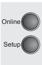
Setup key: Sets the printer to setup mode. - Online key: Sets the printer to offline mode. Loaded paper will be transported to printing position. If the printer is set to online mode by pressing the Online key again, the printer transports the paper in tear position.
Offline mode
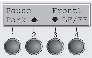
Only in this mode is it possible to perform step, line, or form feeds from the control panel, see Paper transport (page 38); however, data cannot be received.
Park key (1): Clears the paper path with paper loaded and activates paper path quick selection, see Changing the paper path (page 32).
Key (2): Short keypress: Microstep forward. Long keypress: Continuous paper feed.
Key (3): Short keypress: Microstep reverse. Long keypress: Continuous paper reverse feed up to the park position.
- Load key (4): If no paper is loaded, see above.
If paper is loaded: Loads paper from the selected paper source; the display changes to LF/FF
Short keypress: Line Feed (LF).
Long keypress: Form Feed (FF).
Setup key: Sets the printer to setup mode.
- Online key: Sets the printer to online mode.
Setup mode
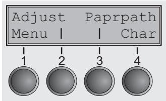
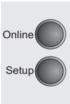
In this mode, the following settings are available:
- Setup key: Sets the printer to setup mode, in which the following settings can be selected:
- Menu key (1): Other menu settings. Acces may be disabled by the manufacturer (see note below).
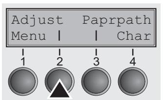
Adjust key (2): Sets the Tear position, first printing line and print head gap.
Paprpath key (3): Sets the Paper path.
Char key (4): Sets the font and number of characters per inch.

Access to the other menu settings (Menu) may be - depending on the model - disabled by the manufacturer.
Proceed as follows to release this lock temporarily.
1 Switch off the printer for approx. 5 seconds.
2 Switch the printer on again keeping the Setup key pressed until Selftest disappears on the display.

For information on how to enable access permanently and about the available settings, refer to the section Menu lock (MenLock) (page 66) and Menu parameters (page 51).

The settings for Font and CPI are lost when the printer is switched off. The section Selecting font (Font) (page 53) explains how to set fonts permanently.
Messages in the LC display
If the printer detects an internal fault or user error or if it expects you to do something, a message will appear in the LC display. It also displays the status during an operation (e.g. Loading default). Below you will find a list of messages with brief descriptions of each message. The messages are described in greater detail in the chapter Error messages via the display (page 112).
| Message | Meaning |
| Eject error | The printer cannot eject the paper/advance it to park position. |
| Hardware Alarm | Internal hardware error, contact your dealer or service technician. |
| Initializing | This message appears during the printer's initializing phase after switching on the printer. |
| Load error | The printer cannot draw in the loaded paper. |
| Load paper from | The printer has detected paper end during operation/printer was switched on with no paper loaded. |
| Loading default | Factory defined parameters will be reloaded in all available menus after switching on the printer. |
| Out of paper | The printer has detected paper end during operation / printer was switched on with no paper loaded. |
| Paperwidth error | Print characters override the detected right paper margin. |
| Parity error | A parity error during data transmission is indicated. |
| Park position | Printer was switched on with no paper loaded. |
| Press any key | The user is requested to press any key. |
| PW sensor defect | The automatic paper width detection cannot detect the left paper margin. |
| Selftest | After power-on, the printer executes a short hardware self-test. |
| Tear Paper off | The user is requested to tear off paper which has been advanced to the tear edge. |
Key functions when turning on the printer
If you keep one of the following keys pressed during power-on until the printer has completed initialisation, the corresponding function is activated:
- If you keep the Online key depressed while turning on the printer, you enter the printer's advanced menu mode. The advanced menu mode is described in the section Advanced menu (page 100) of this manual.
- If you keep the Setup key depressed while turning on the printer, you regain access to the printer menu if you had locked it before with the help of the MenLock function. The MenLock function is described in the section Menu lock (MenLock) (page 66).
- If the four function and select keys (keys 1 to 4) are depressed simultaneously while turning on the power, all printer settings are reset to the default values.

This causes all the user's previous settings to be lost.
- If you keep the key 4 depressed while turning on the printer, a status page is printed out from the active paper source with the selected settings of all menus.

Paper handling
This section describes how to set the paper type, load fanfold paper and single sheets, transport paper and move the paper to the tear position.
Changing the paper path
You can change the paper type either from an application program, by means of the paper path quick selection feature or in the Setup menu. In this section, the quick selection feature is described; for detailed information on how to make this setting via the Setup menu, refer to the section Changing the paper type in the setup menu (page 33).
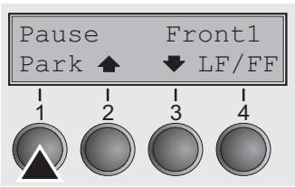
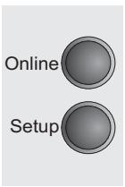
Make sure that the printer is in offline mode (Pause); press the Online key, if necessary.
Press the Park (1) key. If fanfold paper is loaded in the printer, it is fed to the tear position. The text Tear paper off appears in the display.
After having torn off the paper, press any key. If a single sheet is loaded in the printer, it is ejected.
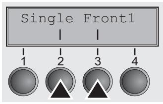
Use one of the marked keys to select the desired paper path, for example, Single (2).

The display shown here may vary depending on which paper options you have installed. If you do not make a selection within 5 seconds, the menu is closed.
The display alternates between the basic menu and the menu in the following figure:
Insert a single sheet (for the procedure, see Loading paper (page 34).
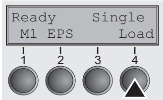
Press the Online key to set the printer to ready status. When the printer receives data from the computer, the single sheet is automatically loaded. Press the Load (4) key to load the single sheet before starting the printout.
Changing the paper type in the setup menu
If you wish to change the paper type in the setup menu, proceed as follows.
Press the Setup key followed by the Paprpath key (3).
Select the desired paper type with the key < (2) or (3).
Press the Set (1) key to confirm your selection.
Loading paper
Your printer can process both fanfold paper and single sheets. For information on the supported paper sizes, please refer to section Paper specifications (page 125).

Only use dust-free or low-dust paper. Many paper qualities are suitable for this printer. For more information, please refer to the section Paper specifications (page 125).
Fanfold paper
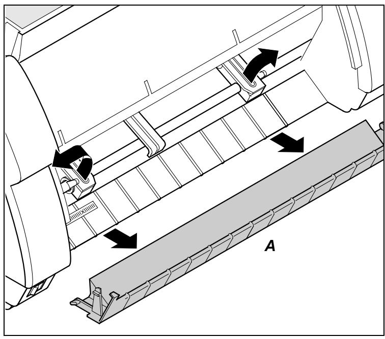
Make sure that the printer is set for fanfold paper printing. If necessary, change the paper type, see Changing the paper path (page 32).
Raise the front cover.
Remove the bottom cover A.
Open the right and left tractor flaps.

Release the colored latch lever of the left-hand tractor and align the tractor so that the first printing position on the paper matches the X mark on the printer housing.
Lock the colored lever again.
Place fanfold paper into the left-hand tractor.
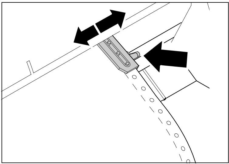
Open the colored latch lever of the right-hand tractor and align it to the paper width.
Insert the fanfold paper into the right-hand tractor.
Make sure that it is inserted by the same length as on the left-hand tractor in order to avoid any paper jam.
Close the tractor flap and lock the tractor by turning the tractor lever to the rear.

Do not tension the paper excessively to avoid tearing the perforation holes; do not allow excessive slack since in this case the paper will bulge and there may be problems in the feeding process.
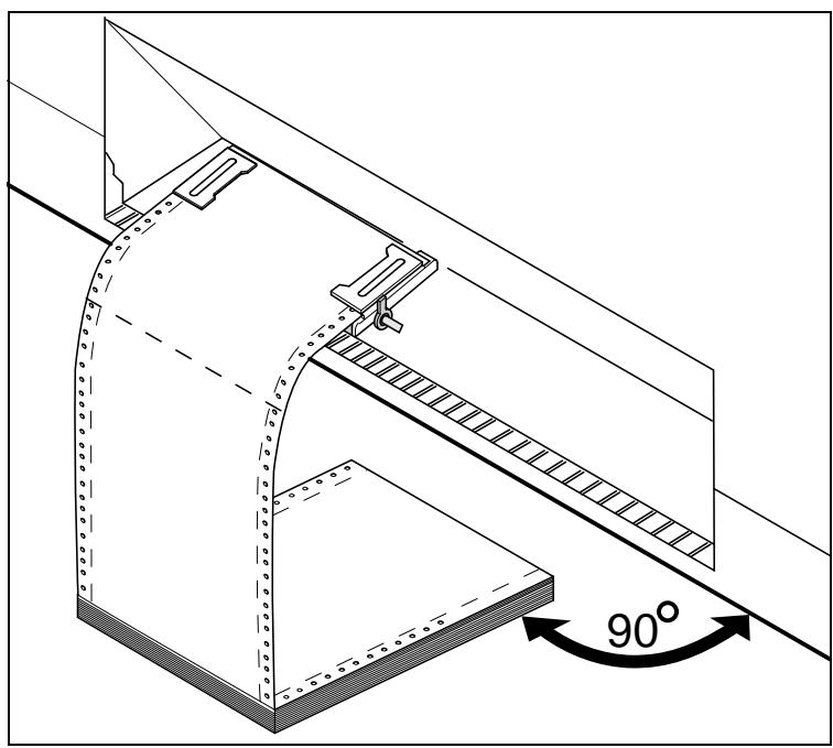
Make sure to align the paper stack in parallel with the printer and that the paper flow is unobstructed.
Re-install the bottom cover.
Lower the front cover.
Switch the printer on. The active paper source (Front1 = tractor 1) appears in the display. The paper is automatically loaded when the printer is in online mode (Ready) and receives data from the computer.

Press the Load (4) key only to load paper before starting the printout.
Single sheets

Some printer models are designed for fanfold paper operation only and therefore do not feature a single sheet feeder. The front cover can therefore not be opened on these models.
Make sure that the printer is set to single sheet mode. If necessary, change the paper type, see Changing the paper path (page 32).
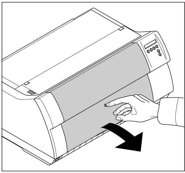
Press the latch at the middle of the front cover. The single sheet input tray opens downwards.
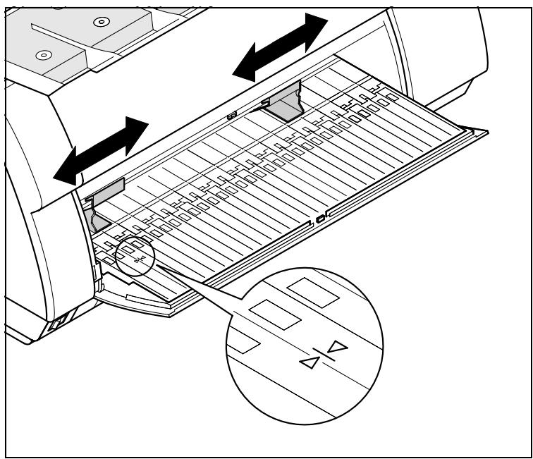
Align the left paper guide with the mark on the left of the single sheet input tray marking the first printing position.
Adjust the right paper guide to the width of the paper used.
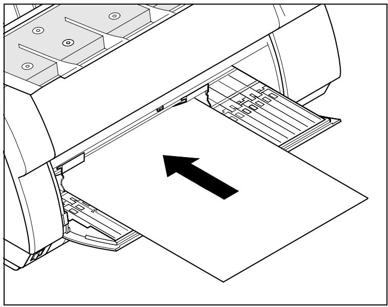
Insert the single sheet into the input tray as far as possible.
Press the Online key to set the printer to ready status. The sheet is automatically loaded when the printer is in online mode (Ready) and receives data from the computer.
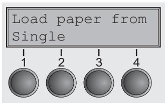
The printer reports a paper out condition by displaying Load paper from single and beeping.
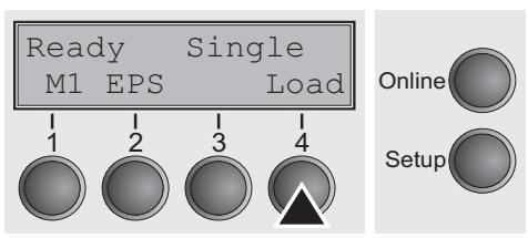
Press the Load (4) key only to load paper before starting the printout.
Paper transport
Online
Setup
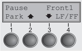
Loaded paper (fanfold paper/single sheets) can be transported in the printer in several ways.
Make sure that the printer is in offline mode (Pause); press the Online key, if necessary.
Key Park (1): If fanfold paper is loaded in the printer, it is fed to the park position or the tear position. If a single sheet is loaded, it is ejected.
Key (2): Short keypress: Paper is transported upwards step by step. Long keypress: Continuous transport upwards.
Key (3): Short keypress: Paper is transported downwards step by step. Long keypress: Continuous transport downwards.
Key LF/FF (4): Short keypress: Line Feed (LF) is effected. Long keypress: Form Feed (FF) is effected.
Key Online (4): Moves Paper to tear position if the automatic tear function is activated.

The maximum value of the paper return feed is 22 inches.
You can not remove paper generally if the Tear parameter is set to No Tear/Reverse in the active macro.
Moving the paper to the tear position
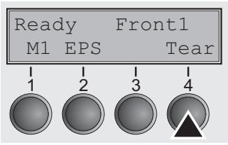
Your printer by default moves the paper into tear position once paper is loaded. If you deactivate this feature in the printer's menu (setting: Manual) you can use the Tear key to move the paper to the tear position. For more information refer to View and tear position (TearView) (page 71).
Swing the soundproofing cover towards the front (see below). The tear edge is located at the front side of the paper output opening.
Make sure that the printer is in online mode (Ready). If necessary, press the Online key.
Press the Tear (4) key. The printer moves the perforation edge of the fanfold paper to the tear edge.
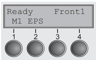
The display changes to...
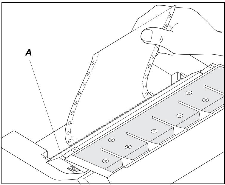
Tear off paper at the tear edge A.

Make sure you tear the paper off straight, otherwise a paper jam may occur.
After having torn off the paper, press the Online key. The printer returns the paper to the first printing position.
If a print job is active, the printer returns the paper automatically to the first printing position.

The tear function can be deactivated completely (No Tear/ Reverse). In this condition the Tear key is not accessible; the paper can not be moved reverse. For more information, please refer to View and tear position (TearView) (page 71).
Removing paper

Never use force to remove the paper from the printer. Otherwise the mechanical components may be damaged.
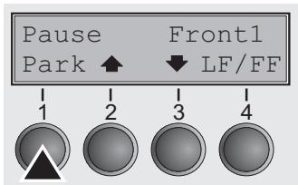
Make sure that the printer is in offline mode (Pause); press the Online key, if necessary.
Press the Park (1) key. If fanfold paper is loaded in the printer, it is fed to the tear position. The text Tear paper off appears in the display.
Now remove the paper from the tractor. Then press any key. If a single sheet is loaded in the printer, it is ejected.
Settings
This section describes how to set the tear position, the first printing line, the print head gap as well as the font and the character density.
Setting the tear position
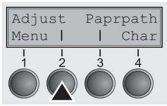
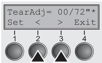
If the tear position of the paper is not aligned with the tear edge of the printer, you can adjust it. Inserted paper needs to be torn off if necessary and retracted to park position.
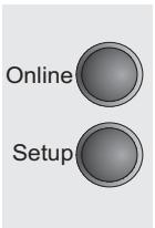
Press the Setup key. The printer changes to setup mode.
Press the Adjust (2) key.
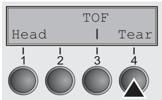
Press the Tear (4) key.
Swing the soundproofing cover towards the front (see Printer at a glance, page 3). The tear edge is located at the front side of the paper output opening.
Press the (2) or > (3) key to move the perforation to the desired position. Confirm the input by pressing the Set (1) key. Confirm the input again by pressing the Setup key. The printer is reset to the initial status.

The correction made – a maximum of approx. 1'' (2.5 cm) in each direction – will be retained after switching the printer off. It can be set separately for each paper path.
Make sure that the set form length corresponds to the actual length of the forms you are using.
Setting the first printing line (TOF)
You can use the TOF function for setting the position of the first printing line for each paper source and each menu individually.

Before using the TOF function (if fanfold paper is used), you should first set the tear position; see Setting the tear position (page 41).
Swing the soundproofing cover towards the front (see Printer at a glance, page 3).
Press the Setup key. The printer changes to setup mode.
Press the Adjust (2) key.
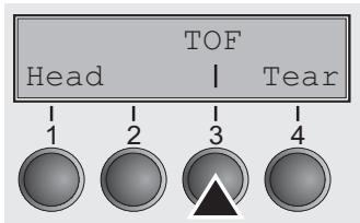
Press the TOF (3) key.
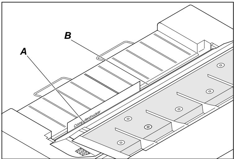
The paper is fed to the position where the bottom edge of the first printing line A is aligned with the tear edge B of the printer. The factory setting for the first printing position (TOF) is 12/72'' (4.23 mm). This is equivalent to the second line from the top.
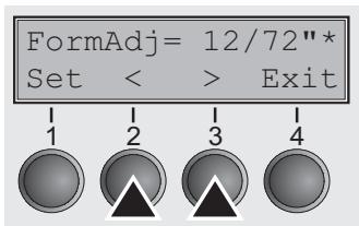
Press the (2) or > (3) key to move the first printing line to the desired position. You can set values from 0 to 220 / 72'' for fanfold paper or for single sheets.
Confirm the input by pressing the Set (1) key. Press the Setup key. The printer returns to the initial status.

The selection made will be retained after switching off the printer.
Setting the print head gap
The printer features automatic print head gap adjustment to the thickness of the paper used. In setup mode, you can enter a correction value to modify the head gap that is normally determined automatically. This correction is useful for modifying the appearance of the type face. This correction will modify the appearance of the font. It may be necessary to obtain optimum printing results on certain paper types.

The AGA (automatic gap adjustment) function must be set to On. For more detailed information, refer to the section Automatic gap adjustment (AGA) (page 77).
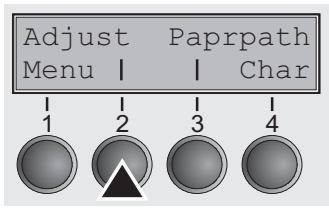
Press the Setup key. The printer changes to setup mode.
Press the Adjust (2) key.
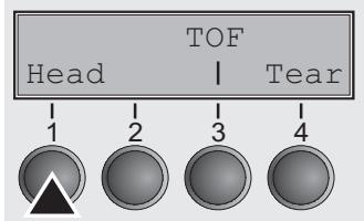
Press the Head (1) key.
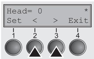
Use the (2) or (3) key to set the range within which the automatic gap adjustment is to be corrected. You can select values in the range from -10 to +10. Negative values reduce the head distance, positive values increase it.
Confirm the input by pressing the Set (1) key.
Press the Setup key. The printer returns to the initial status.

Negative values decrease the print head gap, positive values increase it. Changing the automatically determined value may have a strong effect on the printing quality. The setting made will be retained after switching off the printer.
Selecting character density and font (temporarily)
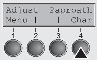
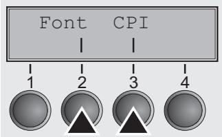
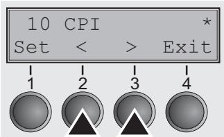
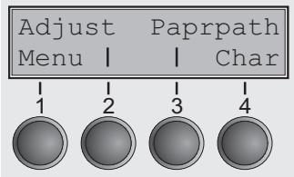
You can use the CPI (Character Per Inch) key in setup mode to select the number of characters per inch to be printed.
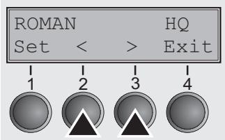
You can use the Font key to select resident fonts.
Press the Setup key. The printer changes to setup mode.
Press the Char (4) key.
Press the CPI (4) or Font (1) key (in our example, press CPI).
Use the < (2) or > (3) key to set the desired character density. Confirm the selection by pressing the Set (1) key.
You can cancel the selection and leave the setting unchanged by pressing the Exit (4) key.
If you pressed the Font (1) key, use the < (2) or > (3) key to select the desired font. Confirm the selection by pressing the Set (1) key.
You can cancel the selection and leave the setting unchanged by pressing the Exit (4) key.
Press the Setup key. The printer returns to the initial status.
It is also possible to press the Online key. The printer then changes directly to online mode.

The selection made will not be retained after switching off the printer. For more details on how to set fonts permanently, please refer to the chapter Selecting font (Font) (page 53).

The Menu
Programming via the control panel
Apart from being able to control your printer via the applications software you use, you can also program the printer directly. There are two programming options you can use:
Programming via the control panel.
- Programming via the interface using Escape sequences or control codes.

Settings made by escape sequences have priority over settings made in menu mode; therefore they will override these. Informations on Escape sequences can be found in Appendix E, Emulations (page 131).
Programming via the interface gives you far greater freedom for designing your printed pages, however, it is also a more sophisticated method and requires some experience with programming languages and printer control systems.
All programming via the interface is lost after you turn off the printer, whereas the programming carried out using the control panel, is saved and stored even after you turn off the printer.
Enabling access to menu mode
On some printer models the menu can be locked by default to protect it from accidental or unauthorised access.
Proceed as follows to release this lock temporarily.
- Switch off the printer for approx. 5 seconds.
- Switch the printer on again keeping the Setup key pressed until Selftest disappears from the display.

For information on how to enable access permanently and about the available settings, refer to the section Menu lock (MenLock) (page 66).
Calling up the menu
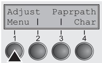
You can access the menu in the following way:
Press the Setup key. The printer switches to Setup mode. (The Setup mode can be selected both in the Online and Offline mode.)
To access the printer menu, press the key directly underneath the word Menu (1).
Menu configurations (Macros)
Every printer is shipped with factory default settings. Basic settings such as emulation, character size, form length etc., which many applications make use of, are set. At the end of this chapter you will find a menu printout (Seite 99) which shows you the printer's default settings.
Your printer allows you to set and use four independent menu configurations (Macros). If one of your applications for example requires an IBM printer while another program works better with an EPSON printer, you can set an IBM emulation configuration with the desired settings, and set the second configuration as an EPSON emulation.
The active macro is always the one you used last. When you switch on the printer for the very first time, macro no. 1 is loaded. Macro no. 1 only remains active until you load another macro. The last active macro is stored even after the printer is switched off and is reloaded automatically when the printer is switched on again.
For example, to change from macro no. 1 to macro no. 3:
Press Setup key.
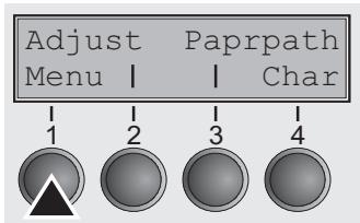
Press Menu (1) key.
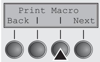
Press Macro (3) key.
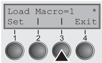
Now the following message appears in the LC display:
Now press the < (2) or > (3) key repeatedly until Load Macro=3 appears.
Then select menu no. 3 as the current setting using the Set key (1).
The currently active setting is marked with an asterisk () .
If changing macros it is possible that the printer initializes due to different emulation settings.

Menu handling
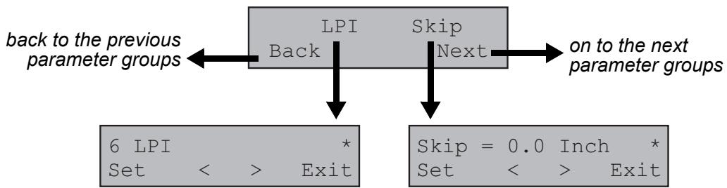
You can navigate in the current menu using the four function and selection keys arranged below the LC display field. Each function and parameter displayed in the LCD is executed or selected by the corresponding key below, respectively. Usually two parameter groups are combined at one level. In the following example, these are the LPI and Skip parameter groups.
If you do not wish to change one of the two parameters you can either press the Next key (to access the two following parameter groups in the menu), or you can press the Back key (to access the two previous parameter groups in the menu).
If you want to change a setting, (e.g. the line density), then press the LPI key (LPI = lines per inch) to access the actual parameter level.
The currently valid setting is marked by a (in the example below the current setting is 6 lpi). With the < and > keys you can view the other parameters available for this setting.
Example:
Save settings
Once the desired parameter is displayed on the LC display, you can save it by pressing the Set key. The parameter is then set and the printer automatically displays the parameter groups again. With the Exit key you can leave the sublevel without saving your changes.
Selecting the LC display language
This section describes how to make settings in the menu, using the selection of the national language as an example.
This example shows how to change from the English language to the German language. The same procedure applies to the other languages (French, Italian and Spanish).
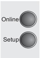
Select the Setup mode by pressing the Setup key.
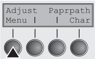
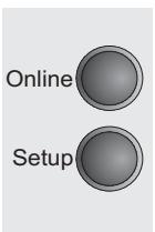
Press the Menu key (1).

Setup mode and Menu mode may be disabled. Hold down the Setup key while switching on the printer to enable menu mode. If you want to enable access to this mode permanently, you need to change the appropriate setting in the menu; see Menu lock (MenLock) (page 66).
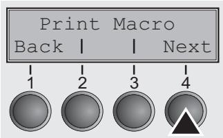
Press the Next key (4) several times until the display indicates Language.
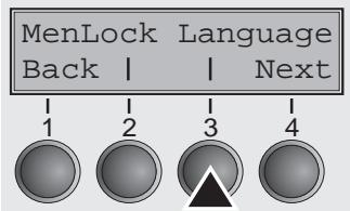
Press the Language key (3).
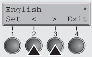
The display now changes to Parameter mode and indicates English in the top line.
The lower line displays Set and Exit. The two arrows < (2) and > (3) represent the symbols for parameter selection (" < ") indicates descending and " > " ascending). Press the < (2) or > (3) key until the desired language is displayed, in our example German.
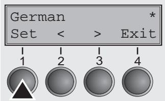
Save your selection by pressing the Set key (1). An acoustic signal verifies this action.
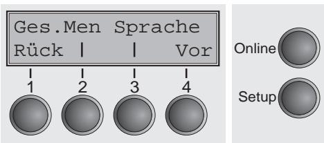
You can exit Parameter mode without saving a setting by pressing the Exit key (4), the old setting is retained.
After saving your setting (Set), the display in our example indicates the following text:

This setting is retained even after switching off your printer.
Terminating Setup mode
Press either the Setup key to change into Offline mode (Pause) or the Online key to change to Online mode (Ready).
Menu structure
The menu structure of your printer may be slightly different from the example shown here, depending on the printer software.
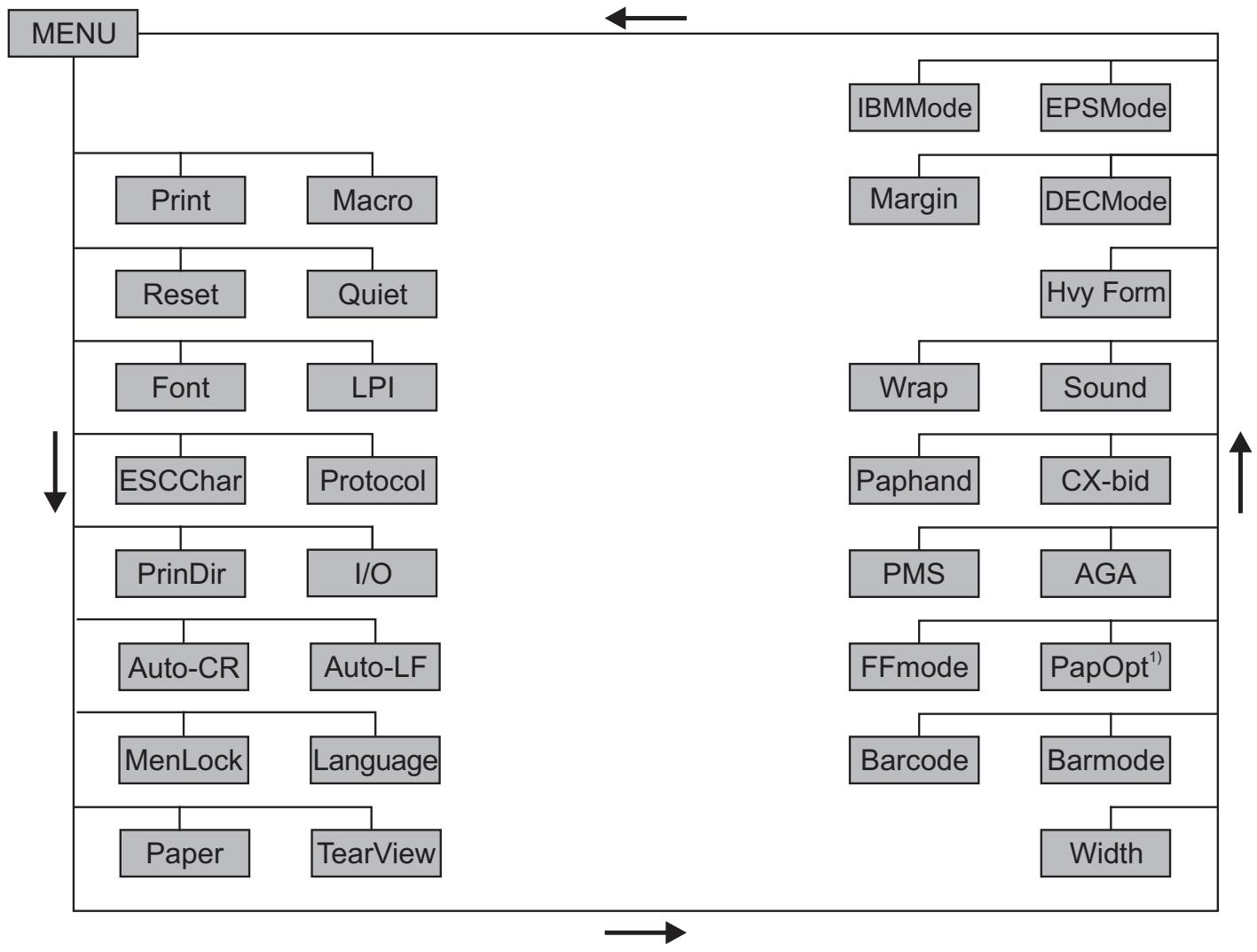
1) only with installed optional paperway
Menu parameters
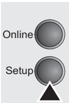
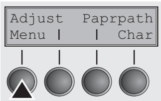
The following section introduces and explains all the possible menu settings.
Press Setup key.
Press Menu (1) key.

Setup mode and Menu mode may be disabled. Hold down the Setup key while switching on the printer to enable menu mode. If you want to enable access to this mode permanently, you need to change the appropriate setting in the macro; see Menu lock (MenLock) (page 66).
Printing out macro configurations (Print)
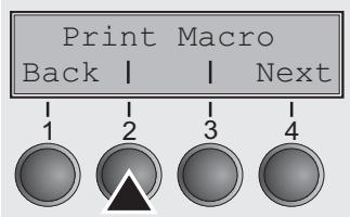
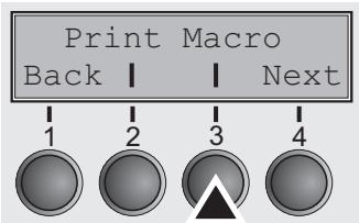
Prints the menu configurations using the active paper feed; see Menu settings (example) (page 99).
Press Print (2) key, to start the printout.
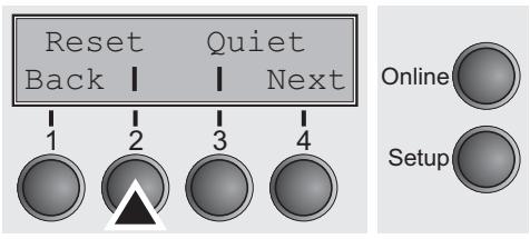
Loading menu configurations (Macro)
A menu is loaded, you can choose between four menus; see Menu handling (page 47).
Press Macro (3) key.
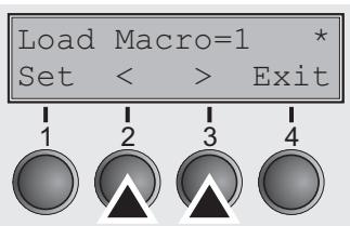
Use the < (2) or > (3) key to select the desired setting.
Setting Options: Load Macro=1/2/3/4
Default Setting: Load Macro=1
Confirm the setting by pressing the Set key (1). Press the Next key (4) to access the next group of parameters.
Reset to default values (Reset)
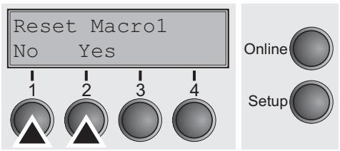

The current macro returns to the default values (factory settings).
Press Reset (2) key.
Press the No (1) or Yes (2) key to select the desired setting.
All manually altered settings in the current menu are lost when it is reset to the default settings.
We therefore recommend that you print out the menu first.
Confirm the setting by pressing the Set key (1).
Quiet mode printing (Quiet)
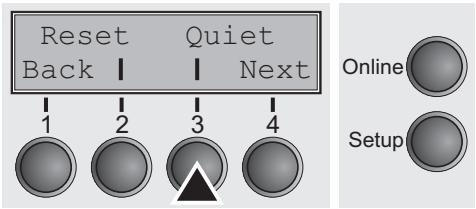
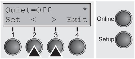
Switches between normal and quiet mode printing. For all printing modes, the print-out is made with the bidirectional method in quiet mode printing. In the first step the first row of pins is activated, during the second step the second row is used.
Press Quiet (3) key.
Use the < (2) or (3) key to select the desired setting.
Setting Options: Off/On
Default Setting: Off
Confirm the setting by pressing the Set key (1). Press the Next key (4) to access the next group of parameters.
Selecting font (Font)
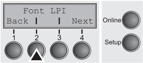
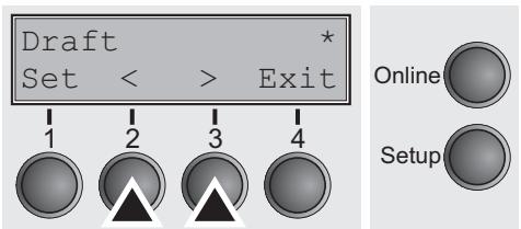
This parameter selects the character style and its quality permanently.
Press Font (2) key.
Use the < (2) or (3) key to select the desired setting.
Setting Options: see table below
Default Setting: Draft
Character styles marked with an I (for example Courier I LQ) are IBM compatible fonts.
Fonts with the identifier PS in their name are proportional fonts which use only the space actually required for the character width.
Example:
Roman LQ: W i l l i
Roman PS LQ: Willli
The abbreviation NLQ stands for Near Letter print quality, which means that the printer works faster but with a slightly lower resolution. LQ stands for Letter Quality, which means that the resolution is higher at the expense of a slightly slower speed.
| Available fonts | ||
| Draft | S Serif PS LQ | OCR-A NLQ |
| Draft Copy | Courier NLQ | OCR-A LQ |
| Roman NLQ | Courier LQ | Courier I NLQ |
| Roman LQ | Prestige NLQ | Courier I LQ |
| Roman PS NLQ | Prestige LQ | Cour I PS NLQ |
| Roman PS LQ | Script NLQ | Cour I PS LQ |
| Sans Serif NLQ | Script LQ | Orator NLQ |
| Sans Serif LQ | OCR-B NLQ | Orator LQ |
| S Serif PS NLQ | OCR-B LQ | High Speed |
Confirm the setting by pressing the Set key (1).
Setting line spacing (LPI)
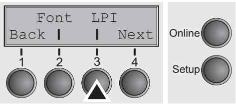
Sets the lines per inch (line density). The higher the parameter the smaller the line spacing (random LPI can be selected via the ESC sequences).
Press LPI (2) key.
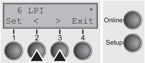
Use the < (2) or > (3) key to select the desired setting.
Setting Options: 2 LPI, 3 LPI, 4 LPI, 6 LPI*, 8 LPI, 12 LPI
Default Setting: 6 LPI
Confirm the setting by pressing the Set key (1). Press the Next key (4) to access the next group of parameters.
Selecting start signal for escape sequence (ESC-Char)
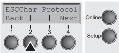
Selects the start signal for control sequences. Setting ESC: Only character Escape (27d, 1Bh) can be used. Setting ESC+$: Character Escape or alternatively two characters ($$) can be used.
Press ESCChar (2) key.
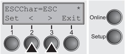
Use the < (2) or > (3) key to select the desired setting.
Setting Options: ESC/ESC+\\\$
Default Setting: ESC
Confirm the setting by pressing the Set key (1).
Selecting Protocol (emulation)
- Selects the emulation for the serial or parallel interface. When a printer understands the control set written for another printer type, it is said to emulate the other printer.

The selected emulation of the active interface is shown in online or offline mode in the second line of the printers display. For more information refer to Online mode (page 28)
MTPL is also active in IBM or Epson emulation mode.
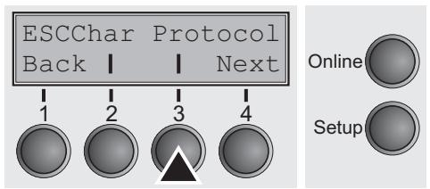
Press Protocol (3) key.
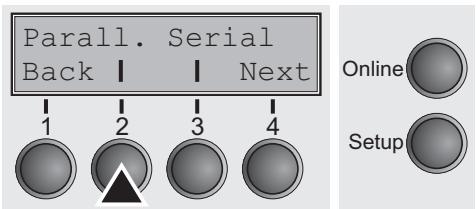
Press Parall. (2) if you want to select a emulation for the parallel interface or Serial (3) if you want to select a emulation for the serial interface of the printer (in our example: Parall.).
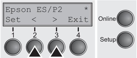
Use the < (2) or (3) key to select the desired setting.
Setting Options: DEC PPL2, Epson ESC/P2, IBM XL24, IBM XL24+AGM,
Default Setting:
Epson ESC/P2 (Parall.)
DEC PPL2 (Serial)
If the printer is switched to online mode after changing the emulation, it performs a reset.
Confirm the setting by pressing the Set key (1). Press the Next key (4) to access the next group of parameters.
Bidirectional printing (PrintDir)
Selects if the printer prints in both directions (bidirectional) or only in one direction (unidirectional from left to right).
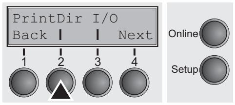
Press PrintDir (2) key.
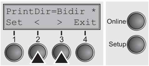
Use the < (2) or > (3) key to select the desired setting.
Setting Options: Bidir/Unidir
Default Setting: Bidir

Normal internal characters will be printed always bidirectional, whereas graphic, semigraphic, large characters (LCP) and barcodes are printed depending on the setting of PrintDir.
Confirm the setting by pressing the Set key (1).
Settings for interfaces (I/O)
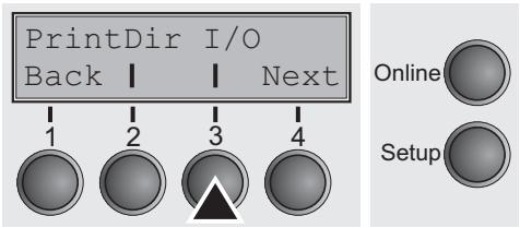
Serial interface (Serial)
In this parameter group, you can choose various settings for the printer interfaces. See also Interfaces (page 133).
Press I/O (3) key.

To ensure the proper functioning of serial data transfers, the serial settings of the printer and computer (host) must coincide.
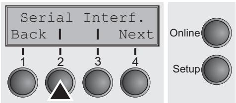
Data transmission rate (Baud)
Press Serial (2) key.
Selects the data transmission rate (baud rate) (baud = bit per second).
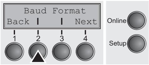
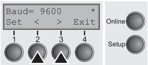
Press Baud (2) key.
Use the < (2) or > (3) key to select the desired setting.
Setting Options: 600, 1200, 2400, 4800, 9600, 19200
Default Setting: 9600

Printer and computer must have the same baud rate.
Confirm the setting by pressing the Set key (1).
Data format (Format)
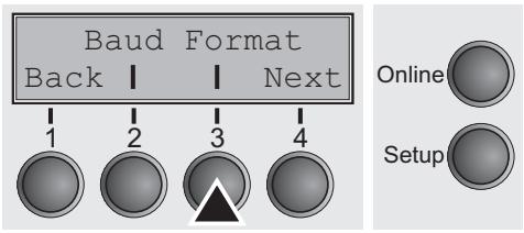
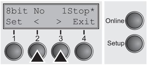
This parameter serves to define the number of data bits, the parity check for received data bytes and the number of stop bits per data byte.
Press Format (3) key.
Use the < (2) or > (3) key to select the desired setting.
Setting Options: see table below
Default Setting: 8 Bit No 1 Stop
| 1 number of data bits | 2 parity test | 3 number of stop bits |
| 8 Bit | No | 1 Stop |
| 8 Bit | No | 2 Stop |
| 8 Bit | Even | 1 Stop |
| 8 Bit | Odd | 1 Stop |
| 8 Bit | Mark | 1 Stop |
| 8 Bit | Spc | 1 Stop |
| 7 Bit | No | 2 Stop |
| 7 Bit | Even | 1 Stop |
| 7 Bit | Odd | 1 Stop |
| 7 Bit | Even | 2 Stop |
| 7 Bit | Odd | 2 Stop |
| 7 Bit | Mark | 1 Stop |
| 7 Bit | Spc | 1 Stop |
| 7 Bit | Mark | 2 Stop |
| 7 Bit | Spc | 2 Stop |
1 Sets the number of data bits: You can select 7 or 8.
2 The parity test for received data bytes can be selected. NO causes transmission in both directions without parity bit. If EVEN or ODD is selected, the bytes are checked if they have even or odd parity. The selection of MARK or SPACE causes a data byte transmission with parity bit, but without checking the received data. Transmission data with parity bit is always marked with 1 (MARK) or 0 (SPACE).
3 Selects one or two stop bits per data byte.
Confirm the setting by pressing the Set key (1). Press the Next key (4) to access the next group of parameters.
Buffer control (BuffCtrl)
This parameter serves to select the type of protocol, i.e. a certain set of rules and procedures for ensuring error-free data exchanges between computer and printer. Details of the available protocols can be found in the section Protocols (page 139).
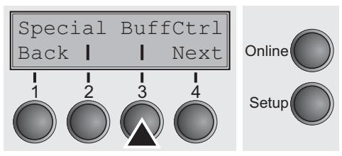
Press BuffCtrl (3) key.
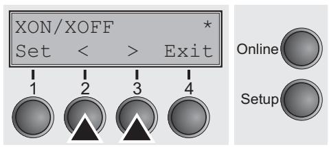
Use the < (2) or > (3) key to select the desired setting.
Setting Options: XON/XOFF, Robust XON/XOFF, Default Setting: XON/XOFF
Confirm the setting by pressing the Set key (1). Press the Next key (4) to access the next group of parameters.
Signal Processing (DTR)
Defines the conductor to which the DTR signal is connected (DTR = Data Terminal Ready).
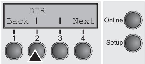
Press DTR (2) key.
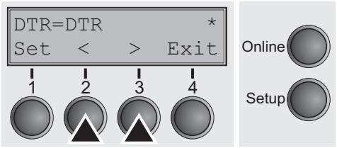
Use the < (2) or > (3) key to select the desired setting.
Setting Options: DTR/READY Default Setting: DTR
DTR=DTR: DTR signal is assigned to DTR line.
DTR=READY: READY signal is assigned to DTR line.
DTR = Pin 20 on 25-pin female V.24 connector.
DTR = Pin 4 on 9-pin female V.24 connector.
Confirm the setting by pressing the Set key (1). Press the Next key (4) to access the next group of parameters.
Selecting interface (Interf.)
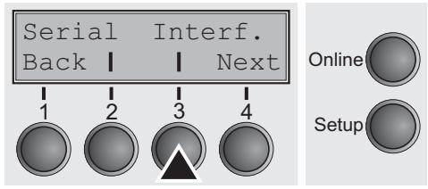
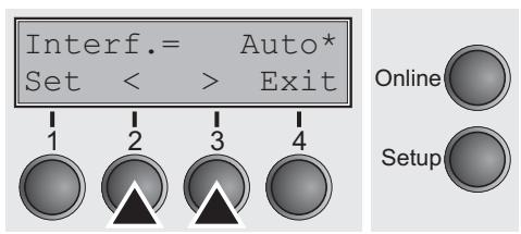
Selects the interface. Printer is configured either for parallel, Ethernet or serial connection or in automatic change for both (Auto).
Press Interf. (3) key.
Use the < (2) or > (3) key to select the desired setting.
Setting Options: Auto, Parallel, Ethernet, Serial Default Setting: Auto
Interf. = Auto: Printer switches automatically between parallel and serial interface.
Interf. = Parallel: Printer using parallel interface.
Interf. = Parallel: Printer using parallel interface.
Interf. Serial: Printer using serial interface.
Confirm the setting by pressing the Set key (1). Press the Next key (4) to access the next group of parameters.
Interface buffer (Buffer)
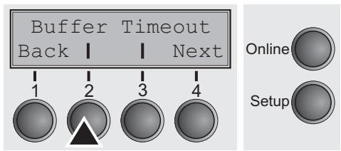
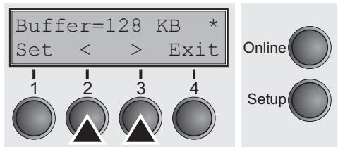
Selects the size of the interface buffer.
Press Buffer (2) key.
Use the < (2) or (3) key to select the desired setting.
Setting Options: 0, 16, 32, 48, 64, 80, 96, 112, 128 KB
Default Setting: 128 KB

If buffer = 0 KB and the serial interface is selected, or if the setting Auto is active, the actual buffer size will be 512 bytes.
Confirm the setting by pressing the Set key (1). Press the Next key (4) to leave the parameter group Interf.. Press the Next key (4) again to access the next group of parameters.
Selecting interface timeout (Timeout)
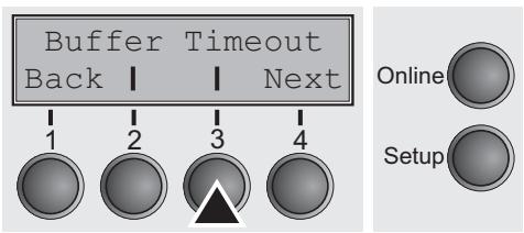
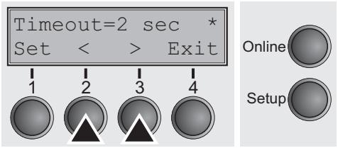
The Timout option allows you to define the duration after which the interface switches back to the Stand-by state, when the printer stops receiving data.
Press Timeout (3) key.
Use the < (2) or > (3) key to select the desired setting.
Setting Options: 2 sec ... 30 sec
Default Setting: 2 sec
Confirm the setting by pressing the Set key (1). Press the Next key (4) to access the next group of parameters.
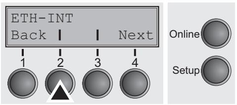
Ethernet interface (ETH-INT)
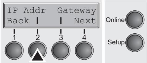
Setting IP address (IP Addr)
Setting Gateway address (Gateway)
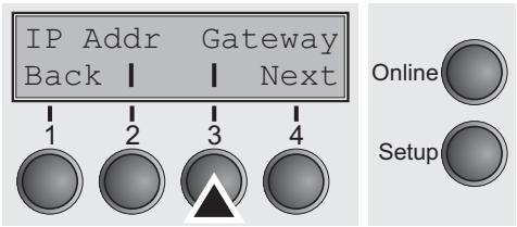
In this parameter group you can choose settings for the internal Ethernet interface.
Press ETH-INT (2) key.
Input of the IP address of the printer.
Press IP Addr (2) key.
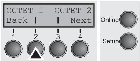
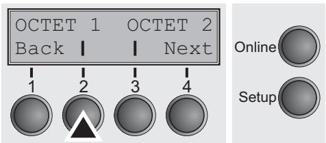
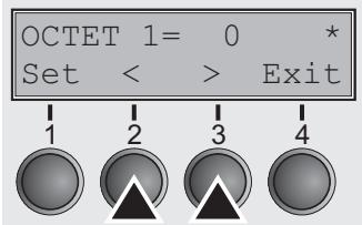
This menu level offers the possibility to set the IP address, which is divided into four digit groups (octet 1 to 4). You can activate octet 3 and 4 by pressing the Next (2) key.
Press OCTET 1 (1) key.
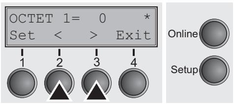
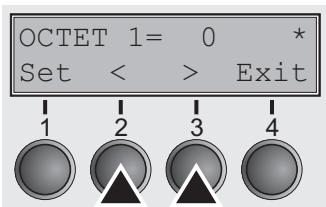
Use the < (2) or > (3) key to select the desired digit.
Setting Options: 0 to 255
Default Setting: 0
Confirm the setting by pressing the Set key (1).
Set the remaining three digit groups in the same way.
Input of the Gateway address of the printer.
Press Gateway (3) key.
This menu level offers the possibility to set the IP address, which is divided into four digit groups (octet 1 to 4). You can activate octet 3 and 4 by pressing the Next (2) key.
Press OCTET 1 (1) key.
Setting Subnet mask (Subnet)
Use the < (2) or > (3) key to select the desired digit.
Setting Options: 0 to 255
Default Setting: 0
Confirm the setting by pressing the Set key (1).
Set the remaining three digit groups in the same way.
Press the Next key (4) to access the next group of parameters.
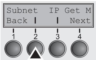
Input of the Subnet mask address of the printer.
Press Subnet (2) key.
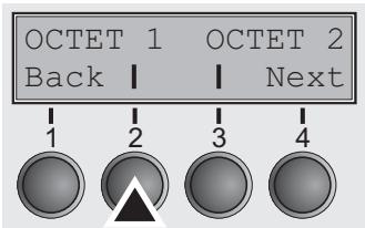
This menu level offers the possibility to set the IP address, which is divided into four digit groups (octet 1 to 4). You can activate octet 3 and 4 by pressing the Next (2) key.
Press OCTET 1 (1) key.
Use the < (2) or > (3) key to select the desired digit.
Setting Options: 0 to 255
Default Setting: 0
Confirm the setting by pressing the Set key (1).
Set the remaining three digit groups in the same way.
IP address administration (IP Get M)
Selects the way of administrating the IP address.
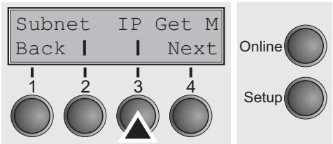
Press IP Get M (3) key.
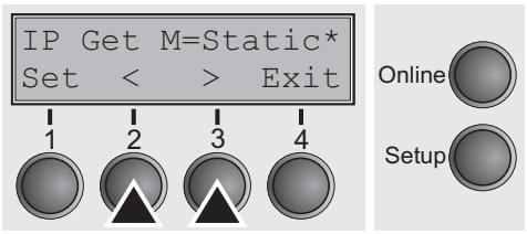
Use the < (2) or (3) key to select the desired setting.
Setting Options: Static, DHCP, BOOTP
Default Setting: Static
Confirm the setting by pressing the Set key (1).
The setting Static is the precondition that the values entered in the parameter IP Addr become valid (see Setting IP address (IP Addr) (page 62). For further informations, refer to the Web Panel Manual on the Online-CD-ROM.
Press the Next key (4) to access the next group of parameters.
Banner page (Banner)
Specifies whether a banner page is to be printed out, when using the LPD/LPR protocol.

Press Banner (2) key.
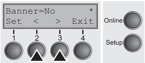
Use the < (2) or > (3) key to select the desired setting.
Setting Options: Yes/No Default Setting: No
Yes: When using the LPD/LPR protocol a banner page will be printed out in front of every print job, containing the file name and the print queue name. The width of the banner page is 8" .
Confirm the setting by pressing the Set key (1).
Press the Next key (4) to leave the parameter group Interf.. Press the Next key (4) again to access the next group of parameters.
Automatic carriage return (Auto-CR)
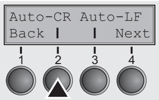
Automatic line feed (Auto-LF)
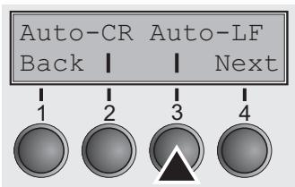
Switches the automatic carriage return on or off after receiving the signal LF (line feed).
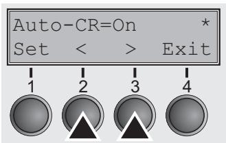
Press Auto-CR (2) key.
Use the < (2) or > (3) key to select the desired setting.
Setting Options: Off/On
Default Setting: On
Confirm the setting by pressing the Set key (1).
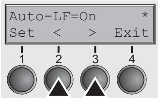
Switches the automatic line feed (LF) on or off after receiving the signal CR (carriage return).
Press Auto-LF (3) key.
Use the < (2) or > (3) key to select the desired setting.
Setting Options: Off/On
Default Setting: Off
Confirm the setting by pressing the Set key (1). Press the Next key (4) to access the next group of parameters.
Menu lock (MenLock)
With MenLock = Off, all functions and settings are accessible without restriction in Online, Offline and Setup mode.
If MenLock = Menu is activated, all functions and settings are still accessible in Online and Offline mode, however, in Setup mode you can only access the parameter groups Adjust (setting the print head gap [Head], top of form [TOF] and tear position [Tear]), Paprpath (setting the paper path), Font (setting the font) and the character spacing (CPI), while access to Menu mode (Menu key) is disabled. If you select MenLock = All, you can access the Online/Offline, Load/Park, Paper and Paper Feed (LineFeed/Form Feed, / ) functions in Online and Offline mode while Setup mode is disabled. In this case, the Setup menu can only be called up by holding the key Setup while switching on the printer.
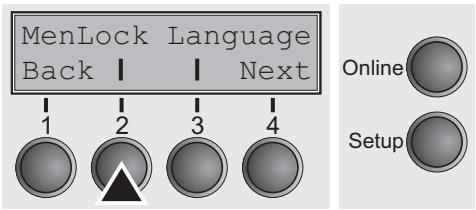
Press MenLock (2) key.
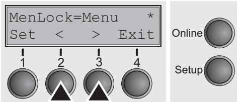
Use the < (2) or (3) key to select the desired setting.
Setting Options: Off, Menu, All
Default Setting: Off
Confirm the setting by pressing the Set key (1).
Language (Language)

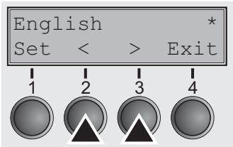
The menu can be shown in five languages on the LC display.
Press Language (3) key.
Use the < (2) or > (3) key to select the desired setting.
Setting Options: English, German, French, Italian, Spanish
Default Setting: English
Confirm the setting by pressing the Set key (1). Press the Next key (4) to access the next group of parameters.
Paper parameters (Paper)
Selects the paper parameters Formlen (form length), FormAdj (first printing position) and Head (print head gap, only if AGA=Off) separately for each paper source in the current menu.

Only installed options can be selected.
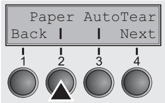
Press Paper (2) key.
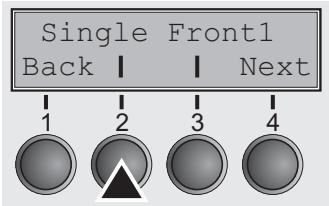
You can now choose between the following paper options:
Single
Front1 (tractor 1)
Front2 (tractor 2 front, option)
Select the desired paperway, in our example Single (2). Press Next (4) key, to proceed to the installed optional paperways.
Form length (Formlen)
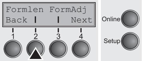
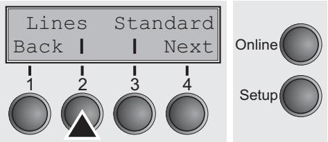
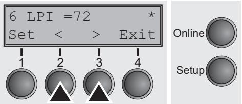
You can define the form length in one of two ways: via the number of lines or via standard formats (e.g. Letter, Legal).
Press Formlen (2) key.
If you wish to define the form length via a line format, press Line (2) key.
Use the < (2) or > (3) key to select the desired setting.
Setting Options: 6 to 132
Default Setting: 66
Sets the form length via line formats. Please note that the adjustment in Lines depends on the selected LPI. For example 8 LPI at a selected line number of 96 lines results in a formlength of 12 inches (96 lines/[8lines/inch]) = 12 inches). The selectable range is between 3 and 21 inches, i.e. for 2 LPI from 6 to 42 lines and for 12 LPI from 24 to 262 lines.
If the form length is set it will not be changed by changing the LPI later on.
Confirm the setting by pressing the Set key (1).
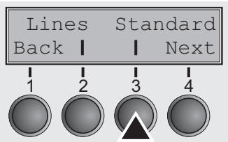
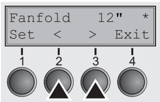
If you wish to define the form length via standard formats, press Standard (3) key.
Use the < (2) or > (3) key to select the desired setting.
Setting Options: DIN A3, DIN A4, DIN A5, DIN B5, DIN B6, DIN C6, Executive 10.5", Letter 11", Fanfold 12", Legal 14", No Format
Default Setting: Letter 11"
Selects the form length by standard formats. Using Standard, different paper formats can be selected directly, e.g. DIN A4, Legal, Letter.
The LC display indicates No format if a value is selected by the Line function or ESC sequences, which does not correspond to a standard format.
Confirm the setting by pressing the Set key (1).
First printing position (FormAdj)
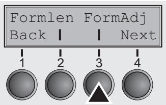
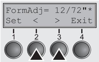
Sets the first print position of a form in n/72 inch, separately adjustable for each paper path.
The settings made here reduce the height of the printable area.
Press FormAdj (3) key.
Use the < (2) or > (3) key to select the desired setting.
Confirm the setting by pressing the Set key (1). Press the Next key (4) to access the next group of parameters.

An alternative notation for FormAdj is TOF (Top Of Form).
Print head gap manually (Head)
This parameter is ignored if the automatic gap adjustment (AGA) is activated; see Automatic gap adjustment (AGA) (page 77).
Adjusts the print head gap manually; separately adjustable for each paper path.
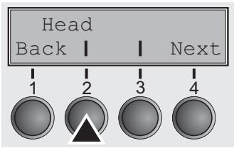
Press Head (2) key.
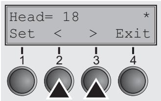
Use the < (2) or > (3) key to select the desired setting.
Setting Options: 0 to 100
Default Setting: 18
Select the Head = 18 parameter for normal paper. Use a greater distance for thicker paper.
Recommended values for the print head gap:
| 1 layer | 2 layers | 3 layers | 4 layers | 5 layers | 6 layers |
| 18 | 26 | 34 | 42 | 50 | 58 |

If you change this value, this may affect the print quality.
Confirm the setting by pressing the Set key (1). Press the Next key (4) to access the next group of parameters.
View and tear position (TearView)
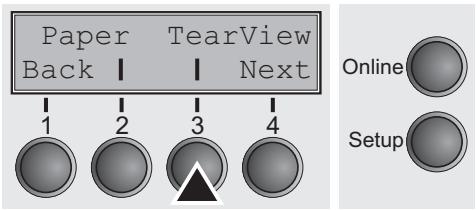
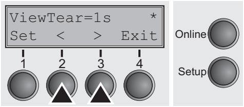
The auto tear or the auto view function can be selected as desired. When auto view is switched on, the last printed text is visible.
When auto tear is switched on, the perforation of the paper is positioned at the tear off edge of the printer, when no data are processed.
Press TearView (3) key.
Use the < (2) or > (3) key to select the desired setting.
Setting Options: View=1s/3s/6s Tear=1s/3s/6s Tear at TOF No Tear/Reverse Manual
Default Setting: Tear=1s
If the parameter View is set to 1s, 3s or 6s, the paper moves to the "normal" print position as soon as data is received. After printing the printer waits for the given interval to bring the paper once more to the auto view position.
If the parameter Tear is set to 1s, 3s or 6s, the perforation of the paper is positioned at the tear off edge of the printer. If data is received, the paper returns to the normal print position. After printing, the printer waits for the given interval to bring the paper once more to the tear off position. If the tear off edge is not aligned with the perforation of the paper, this can be corrected (see Setting the tear position (page 41).
If the parameter No Tear/Reverse is set, TearView mode is disabled and no backward movements are performed.
If the parameter Manual is set, the paper can still be brought into a View or Tear position via a specific sequence or by pressing the Tear key.
If the parameter Tear at TOF is set, the paper perforation is automatically positioned at the tear off edge as long as the current print position TOF is activated. Feeding takes place after approx. 1.5 seconds (hold time). If any data is received during this period of time the paper is not positioned at the tear off edge. With this function it must be noted that the printer may only be switched off when the print position is at TOF.
Confirm the setting by pressing the Set key (1). Press the Next key (4) to access the next group of parameters.
Line length (Width)
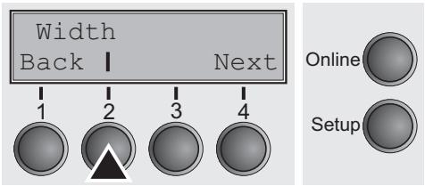

Barcode (Barcode)
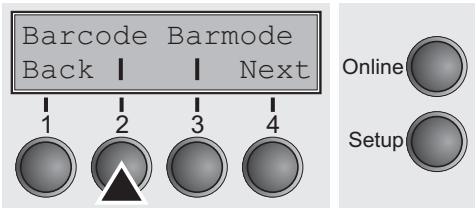
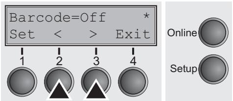
Selects the line length in inches. With the setting of 8 Inch, the printer operates like a printer with a width of only 8 inches.
Press Width (2) key.
Use the < (2) or (3) key to select the desired setting.
Setting Options: 8 Inch, 13.2 Inch, 13.6 Inch
Default Setting: 13.6 Inch
Confirm the setting by pressing the Set key (1). Press the Next key (4) to access the next group of parameters.
With this function selected it is possible to print different barcodes and LCP (Large Character Printing).
Press Barcode (2) key.
Use the < (2) or > (3) key to select the desired setting.
Setting Options: On/Off Default Setting: Off
The definition and activation is performed by special sequences through the interface. Since this selection is possible for all emulations it must be noted that conflicts in sequence conformity with the selected emulation may occur. (The possible barcodes, LCP characters and the operation of these functions are described in the Programmer's Manual).
Confirm the setting by pressing the Set key (1).
Normal characters and barcode (Barmode)
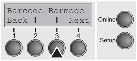
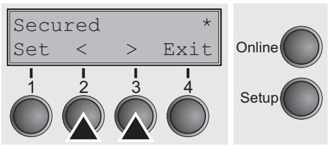
Allows printing of normal characters on the left and right of the barcode.
Press Barmode (3) key.
Use the < (2) or > (3) key to select the desired setting.
Setting Options: Secured/Unsecured Default Setting: Unsecured
In secured mode, the space which the barcode characters require is "protected". In each line, other barcode or normal characters can also be printed. These additional characters are printed in the line currently being printed and and in the subsequent lines, without affecting the barcode which is already being printed. Consequently, normal characters can be printed in every line to the right or left of the barcode.
In unsecured mode, the required paper transport for printing barcodes is carried out automatically, it is not possible to print more than one line of normal characters in the barcode line. All characters in the mixed line are printed such that their bottom edges are in a straight line. This function may be switched on and off by sequences.

This function can be activated/deactivated by sequences.
Confirm the setting by pressing the Set key (1). Press the Next key (4) to access the next group of parameters.
Form feed mode (FFmode)
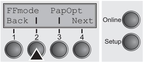
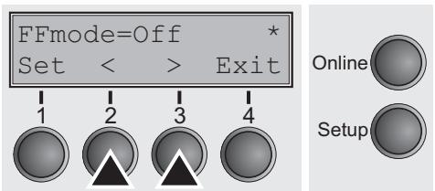
Specifies whether a form feed is to be performed when the paper reaches the top print line.
Press FFFmode (2) key.
Use the < (2) or (3) key to select the desired setting.
Setting Options: On/Off
Default Setting: Off
FFmode = On: If the paper is positioned in the first printing line (TOF), form feeds will be ignored.
FFmode = Off: Form feed will be performed in all cases.
Confirm the setting by pressing the Set key (1).
Setting and activating options (PapOpt)
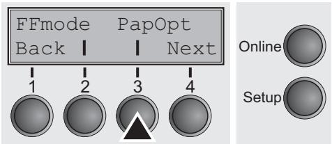
Activation of tractors (AutoTra)
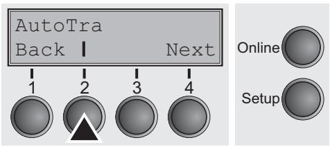
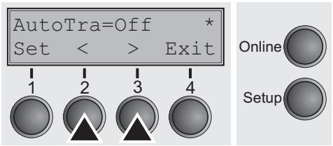
For setting the tractor; see Paperway (page 5).
Press PapOpt (3) key.
This parameter only appears if the optional tractor is installed. It regulates the activation of tractors when there is no more paper left in one of them.
Press AutoTra (2) key.
Use the < (2) or > (3) key to select the desired setting.
Setting Options: Off/T1=T2
Default Setting: Off
If an optional tractor is installed and the Off parameter is activated, only the selected tractor is supported (either via the menu or an ESC sequence). If the selected tractor is out of paper, printing stops.
If an optional tractor is installed and you select T1=T2, the printer will load paper from the other tractor if the selected one is empty.
Confirm the setting by pressing the Set key (1).
Automatic paper motion sensor (PMS)
You can use this function to activate or deactivate the paper motion detection feature. When it is active, printing and paper movements stop in case of a paper jam and an error message is output in the display. Set the printer to test mode by pressing the Online key while you switch on the printer.
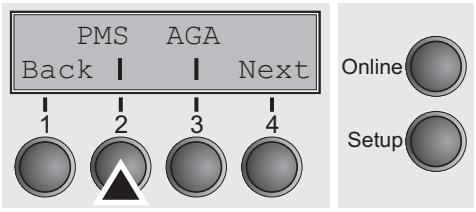
Press the PMS key (2).
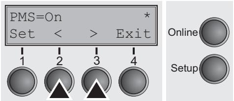
Setting options: On/Off
Default setting: On
PMS=On: The form movements of the active paper path are monitored. In case of a paper jam, printing and paper movements stop and an error message (PAPER JAM) is displayed.
PMS=Off: A paper jam will not produce an error message.

The Paper Motion Sensor (PMS) detects any paper jam or unintended paper end condition and provides efficient protection against any paper transport problems together with the paper end sensor. This prevents the printer from printing on jammed paper or printing without paper. Disabling the PMS can affect the operational reliability of your printer and should therefore be avoided.
Confirm the setting by pressing the Set (1) key. Change to the next parameter group with the Next key (4).
Automatic gap adjustment (AGA)
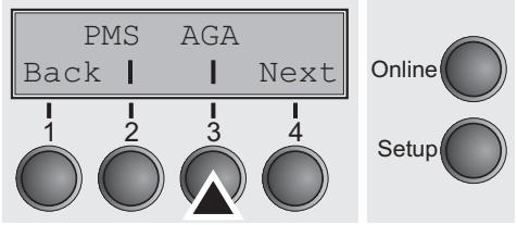
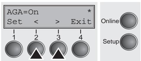
This function allows you to switch the Automatic Gap Adjustment (AGA) off or on.
Press the AGA key (3).
Setting options: Off/On
Default setting: On
AGA=On: printer checks paper thickness and changes gap adjustment if necessary (default). Measurments take place
- after power-on
- in single sheet mode: for each sheet
- in tractor mode: whenever changing the paper path, when loading paper
AGA = Off: selects manual gap adjustment; the value can be set for each paper source and each of the 4 macros available.
Confirm the setting by pressing the Set (1) key. The printer automatically leaves test mode and assumes online mode.
Paper handling (Paphand)
The Paphand group of menus improves the possibilities for the troublefree printing of paper with properties likely to cause problems (perforations etc.) or paper of poor finish.
Put the printer into Menu mode by pressing the Setup key. Press the Menu key. The display shows Print/Macro. Press Next or Back key until the parameter group Paphand/CX-bid appears in the display.
Press the Paphand key (2).
Select the Head up menu (2).
Increasing the print head gap (Head up)
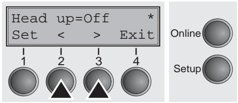

Paper width (Pagewid)
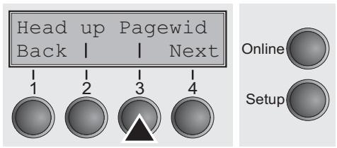
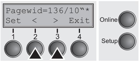
With this function you can increase the print head gap before and after the perforation of the form.
Setting options: On/Off
Default setting: Off
If the parameter is set to On, the print head gap increases during form feed and line feed four lines before and after the perforation on the form (= protected zone). The print head gap is always increased during form feeding past the perforation even when feeding takes place outside the protected zone.

Printing is possible in the protected area.
Confirm the setting by pressing the Set (1) key.
1 Top edge of form
5 Protected zone
2 Paper transport strip
6 Transport holes
3 Bottom edge of form
7 Left-hand area
4 Form separation perforation
8 Right-hand area
This parameter determines the actual paper width.
Press the Pagewid key (3).
Setting options: From 20 to 136 in 1/10 inch steps
Default setting: 136/10 Zoll (136 characters at 10 characters/inch)
If Head up = On, the print head moves to the calculated center of the paper during the time the paper is moving in the protected zone. If Rightzo = On (see below), the print head moves out of the perforation zone on the right as long as the paper is being transported.
Set the printing width rather than the actual paper width.
Confirm your settings with the Set key (1) and press the Next key (4) to access the next group of parameters.
Left-hand area (Leftzon)
If the parameter is On, the print head moves out of the perforation zone (area ⑦) on the left as long as the paper is being transported. The Pagewid setting has no influence (see above).
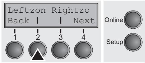
Press the Leftzon key (2).
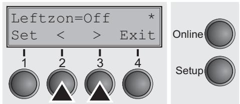
Setting options: On/Off
Default setting: Off
Confirm your settings with the Set key (1).
Right-hand area (Rightzo)
If the parameter is On, the print head travels from the right-hand perforation area (3) towards the center of the paper while the paper is moving. The Pagewid option must be correctly set in this case, see Paper width (Pagewid) (page 78).
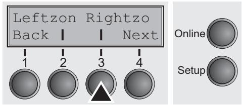
Press the Rightz0 key (3).
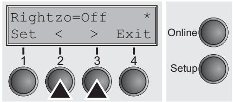
Setting options: On/Off
Default setting: Off

If this parameter is On, the print head carriage travels to the center of the form while the paper is loaded.
Confirm the setting by pressing the Set (1) key. Change to the next parameter group with the Next key (4).
Bidirectional parallel interface (CX-bid)
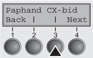
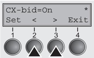
This parameter sets the parallel interface either to bidirectional or to compatibility mode.
Select the CX-bid menu (3).
Setting options: On/Off
Default setting: On
CX-bid = On sets the parallel interface of the printer to bidirectional mode (IEEE 1284, Nibble mode), e.g. for Windows Plug & Play.
CX-bid = Off sets the interface to compatibility mode in order to ensure reliable operation with special external boxes or print server.
Confirm the setting by pressing the Set (1) key. Change to the next parameter group with the Next key (4).
Line wrap (Wrap)
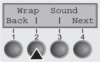
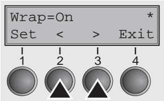
Select the Wrap menu (2).
Setting options: On/Off
Default setting: On
Wrap = On: If more characters than can be printed are transmitted per line, the characters which cannot be printed on this line are printed at the beginning of next line.
Wrap = Off: If more characters than can be printed are transmitted per line, the characters which cannot be printed on this line are cut off.
Confirm the setting by pressing the Set (1) key.
Beep at paper end (Sound)
Generates a beep when paper is empty.
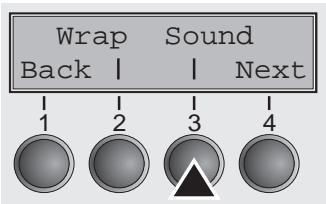
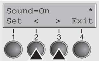
Setting for printing copy paper (HvyForm)
Select the Sound menu (3).
Setting options: On/Off
Default setting: On
When Sound = On, a beep is generated every second to notify that paper is empty.
Confirm the setting by pressing the Set (1) key. Change to the next parameter group with the Next key (4).
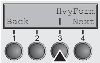
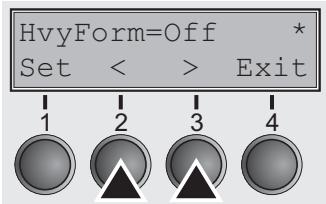
If you set HvyForm = On, the printer prints the same line twice at double strike. This setting ensures that copy paper produces optimum results.
Select the HvyForm menu (3).
Setting options: On/Off
Default setting: Off

With the Copy Draft, NLQ and LQ print qualities, the line is printed twice, however, at single strike.
Confirm the setting by pressing the Set (1) key. Change to the next parameter group with the Next key (4).
Automatic paper width detection (APW)
The automatic paper width detection feature APW prevents the printer from printing beyond the paper edge. This is useful to prevent the printer from printing on the platen, for example, because of an incorrect driver setting.
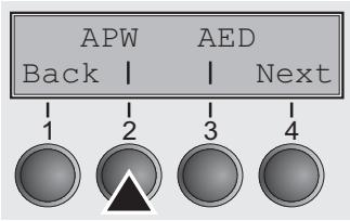
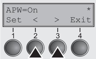
Select the APW (2) menu.
Setting options: On/Off
Default setting: On
If APW=On, the printer is in the standard mode and truncates all data located beyond the right-hand paper edge. These print data are lost.
When you select APW=Off, the printer does not prevent undesirable printing on the platen.
The printer determines the paper width by means of an optical sensor in the print head module. The print head carriage moves once across the maximum possible printable area of the paper and stores the width measured in this process. The measuring process varies, depending on the paper source selected.
Tractor: The measurement is made
after power-on and before the first print job;
after paper end and before the subsequent print job; after
changing the paper source (e.g. from Tractor 1 to Tractor 2).
Single sheet mode: The measurement is made for each printed sheet.
Manual sheet feeder: The measurement is made for each printed sheet.
When you submit a print job which exceeds the paper width, the following message appears in the display:
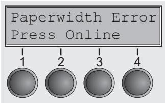

The print job is stopped at the measured paper-end position after printing the first line.
You can now either cancel the print job or load suitable paper. In the latter case, the printer will resume the print job upon pressing the Online key.

If you press the Online key without having changed the paper, another line is printed until reaching the measured paper-end position.

The sensor interprets dark areas with a width of 13mm or more as the right-hand paper edge. If the sensor does not detect any black area, the maximum possible printing width is used as the printable area.

If there is a sensor malfunction (e.g. because of dirt, a defect or misinterpretation of the paper width) it is necessary to deactivate the APW function (APW=Off), since otherwise the printout will be too narrow or there will be no printout at all. In this case contact your service technician.
Confirm the setting by pressing the Set (1) key. Change to the next parameter group with the Next key (4).
Automatic detection of the top paper margin (AED)
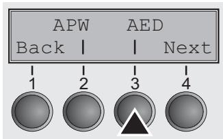


This menu option only appears, if a cut device is installed. It corrects possible inaccuracies of the paper positioning at the tear edge if the paper path is changed after a cutting action.
Select the AED (3) menu.
Setting options: On/Off
Default setting: Off
Confirm the setting by pressing the Set (1) key.
Setting the page margins (Margin)
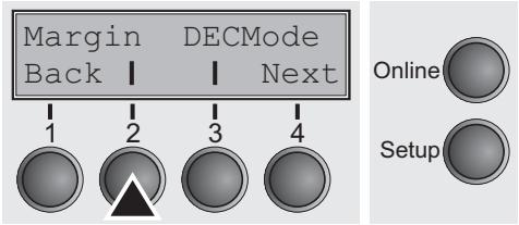
This parameter group allows you to define the area for printing. You can set the top, bottom and left margin.
Press the Margin key (2).
Setting the top margin (Topmrg)
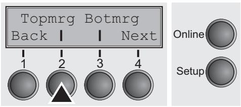
This option lets you set the top margin with the number of the line (numbered from the top paper edge) where the printing actually starts.
Press the Topmrg key (2).
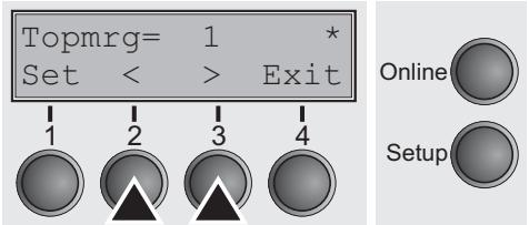
Setting options: Line 1 to Formlength
Default setting: Line 1

The setting of this Option depends on the setting of both the vertical pitch and the form length options. For details refer to Setting line spacing (LPI) (page 54) and Form length (Formlen) (page 68).

Do not set Topmrg equal or higher than Botmrg.
Confirm the setting by pressing the Set (1) key.
Setting the bottom margin (Botmrg)
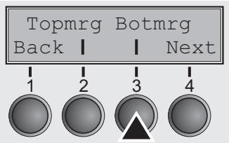

The bottom margin option gives you the possibility to set the bottom margin with the number of the line (numbered from the top paper edge) where the printing actually stops for a given page.
Press the Botmrg key (2).
Setting options: Line 1 to Formlength Default setting: Formlength

The setting of this Option depends on the setting of both the vertical pitch and the form length options. For details refer to Setting line spacing (LPI) (page 54) and Form length (Formlen) (page 68). The Values range from the value for top margin (see Setting the top margin (Topmrg) on page 84) to the value for form length.

Do not set Topmrg equal or higher than Botmrg.
Confirm the setting by pressing the Set (1) key. Change to the next parameter with the Next key (4).
Setting the left margin (Leftmgr)

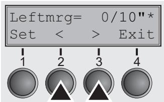
The left margin option is defined by the number of the columns (numbered from the left paper edge) where the printing actually starts.
Press the Leftmrg key (2).
Setting options: 0 to 30/10"
Default setting: 0/10"
Confirm the setting by pressing the Set (1) key. Change to the next parameter group with the Next key (4).
Setting the DEC Mode (DECMode)
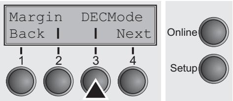
Horizontal spacing of characters (CPI)
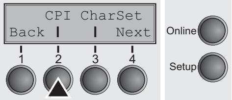
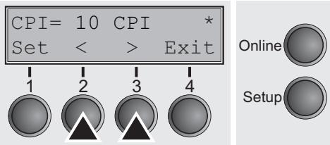
The DEC mode option sets the DEC protocol specific features.
Press the DECMode key (3).
Sets the horizontal spacing of the printed characters used with the DEC protocol.
Press the CPI key (2).
Setting options: 5, 6, 6.65, 8.25, 8.6, 9, 10, 12, 13.3, 15, 16.5, 17.1, 18, 20 cpi and Proportional Spacing
Default setting: 10
Confirm the setting by pressing the Set (1) key.
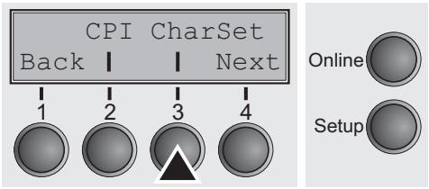
Character set (CharSet)
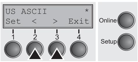
Selects the G0 character set that will be used with the DEC protocol.
Press the CharSet key (3).
Setting options: see table below
Default setting: US ASCII
| Character Set | Definition |
| US ASCII | US ASCII |
| British | British |
| French | French |
| German | German |
| Norw./Danish | Norwegian/Danish |
| DEC Finnish | DEC Finnish |
| DEC French-Can. | DEC French-Canadian |
| DEC Norw.-Dan. | DEC Norwegian/Danish |
| DEC Swedish | DEC Swedish |
| DEC Dutch | DEC Dutch |
| DEC Swiss | DEC Swiss |
| DEC Portuguese | DEC Portuguese |
| DEC Supplement. | DEC Supplemental |
| DEC Spec.-Graphi. | DEC Special Graphics |
| DEC Technical | DEC Technical |
| DEC 7bit Hebrew | DEC 7Bit Hebrew |
| DEC Turkish | DEC 7Bit Turkish |
| DEC Hebrew Sup. | DEC Hebrew Supplemental |
| DEC Greek Sup. | DEC Greek Supplemental |
| DEC Turk. Sup | DEC Turkish Supplemental |
| ISO Italian | ISO Italian |
| ISO Spanish | ISO Spanish |
| JIS Katakana | JIS Katakana |
| JIS Roman | JIS Roman |
| Legal | Legal |
Confirm the setting by pressing the Set (1) key. Change to the next parameter group with the Next key (4).
User preference character set (UserID)
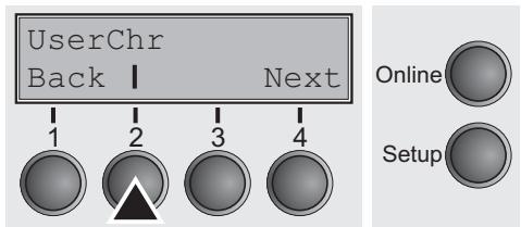
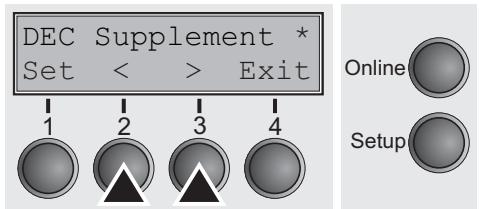
This option sets the user character set for the DEC protocol.
Press the UserChr key (2).
Setting options: see table below Default setting: DEC supplement
| DEC Finnish | ISO Latin-Hebr. Su | Code Page 853 |
| French | ISO Latin-Cyr. Sup | Code Page 855 |
| DEC French-Can. | ISO Latin-5 Su | Code Page 857 |
| German | ISO Latin-9 Su | Code Page 858 |
| ISO Italian | E-USA | Code Page 860 |
| JIS Roman | E-France | Code Page 861 |
| DEC Norw./Dan. | E-Germany | Code Page 862 |
| ISO Spanish | E-United Kingd | Code Page 863 |
| DEC Swedish | E-Denmark 1 | Code Page 864 |
| Norw./Danish | E-Sweden | Code Page 865 |
| DEC Dutch | E-Italy | Code Page 866 |
| DEC Swiss | E-Spain 1 XXX | Code Page 869 |
| DEC Portuguese | E-Japan | Abicomp |
| Legal | E-Norway | Brazilian ASCII |
| DEC Supplement | E-Denmark 2 | Mazowan |
| DEC Spec.Graph. | E-Spain 2 | Code MJK |
| DEC Technical | E-L. America | Bulgarian |
| DEC 7Bit Hebrew | E-Turkey | ISO 8859-7 |
| DEC Hebrew Sup. | E-Korea | ISO 8859-15 |
| DEC Greek Sup. | E-Legal | ISO Latin 1T |
| DEC 7Bit Turk. | E-Old Hebrew | New Hebrew |
| DEC Turk. Sup. | Code Page 437 | D-Hebrew |
| JIS Katakana | CP 437 Greek | Code Page 210 |
| ISO Latin-1 Su | Code Page 850 | Code Page 220 |
| ISO Latin-2 Su | Code Page 851 | |
| ISO Latin-Greek Su | Code Page 852 |
Confirm the setting by pressing the Set (1) key. Change to the next parameter group with the Next key (4).
Printer ID (Prn.ID)
This option defines the DEC printer ID used by the printer when responding to DA commands (DA = device attributes, see Programmer's Manual, Reports. from your host computer or application software (serial transmission only).
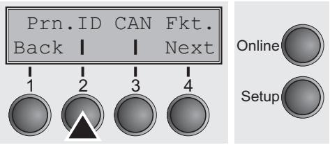
Press the Prn.ID key (2).
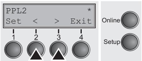
Setting options: PPL2, LA120 ID, LA210 ID
Default setting: PPL2
PPL2: Allows the printer to respond as a DEC Conformance Level 2 device.
LA120 ID: The printer responds as a LA120 printer.
LA210 ID: The printer responds as a LA210 printer.
Confirm the setting by pressing the Set (1) key.
Deleting sequence or buffer (CAN Fkt.)
This option defines the behaviour of the cancel function.
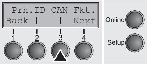
Press the CAN Fkt. key (3).
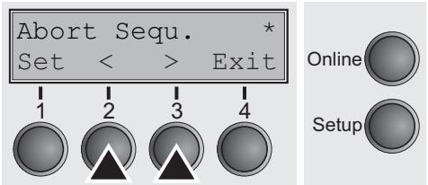
Setting options: Abort Sequ./Kill Buffer Default setting: Abort Sequ.
If Abort Sequence is set, the printer immediately deletes the currently processed sequence (without execution). If Kill buffer is selected, the printer immediately deletes the complete receiving buffer, even if a prior X-OFF was sent to printer.
Confirm the setting by pressing the Set (1) key. Change to the next parameter group with the Next key (4).
Disconnection on end of transmission (Discnct)
This option determines whether the communication disconnect occurs at the end of the transmission.
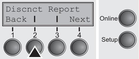
Press the Discnt key (2).
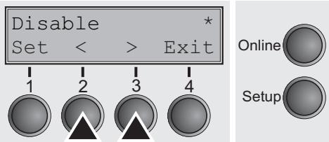
Setting options: Enable/Disable
Default setting: Disable
Confirm the setting by pressing the Set (1) key.
Initial Report (Report)
This option determines whether the printer sends an initial report to the host or not.
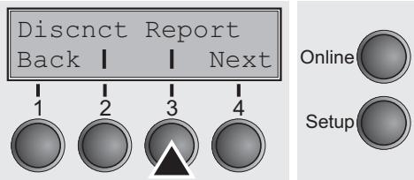
Press the Report key (3).
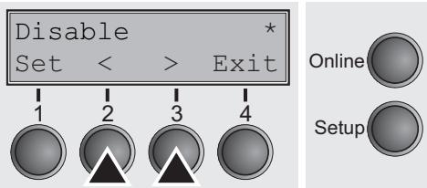
Setting options: Enable/Disable
Default setting: Disable
Confirm the setting by pressing the Set (1) key. Change to the next parameter group with the Next key (4).
Automatic answerback (Answerbck)
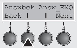
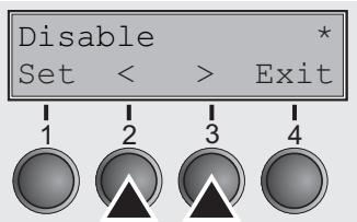
Answerback on ENQ (Answer_ENQ)
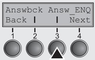
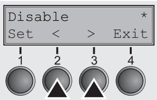
This option determines whether the printer sends an answerback message to the printer during initialization or not.
Press the Answer key (2).
Setting options: Enable/Disable
Default setting: Disable
Confirm the setting by pressing the Set (1) key.
This option determines whether the answerback message is sent to the host when the printer receives an ENQ code.
Press the Answer key (3).
Setting options: Enable/Disable
Default setting: Disable
Confirm the setting by pressing the Set (1) key. Change to the next parameter group with the Next key (4).
Setting the IBM mode (IBMMode)
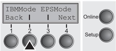
Horizontal spacing of characters (CPI)
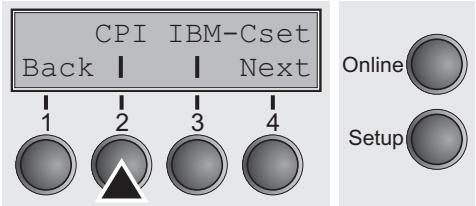
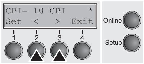
IBM character set (IBM-Cset)
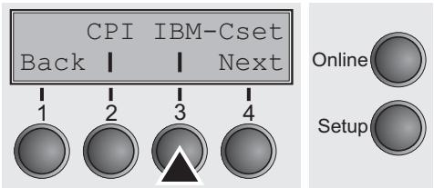
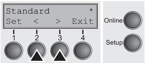
The IBM mode option sets the IBM specific features.
Press the IBMMode key (2).
Sets the horizontal spacing of the printed characters used with the IBM protocol.
Press the CPI key (2).
Setting options: 5, 6, 7.5, 8.6, 10, 12, 15, 17.1, 20 cpi and Proportional Spacing
Default setting: 10
Confirm the setting by pressing the Set (1) key.
This option identifies which kind of character set is to use: for English (IBM standard characters) or non English languages (IBM extended characters).
Press the IBM-Cset key (3).
Setting options: Standard/Extended
Default setting: Standard
Confirm the setting by pressing the Set (1) key. Change to the next parameter group with the Next key (4).
Code page (CodPage)
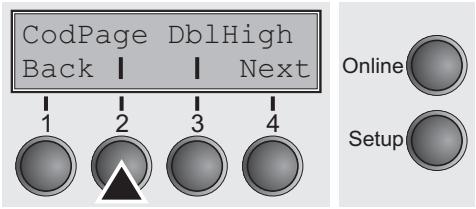
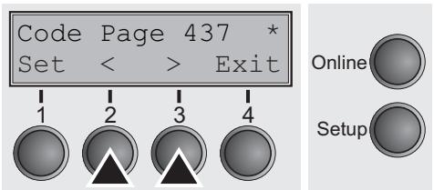
This option determines which code page the printer uses in IBM mode.
Press the CodPage key (2).
Setting options: see table below
Default setting: Code Page 437
| E-Denmark 2 | US ASCII | |
| E-Spain 2 | British | ISO Latin-Greek |
| E-L. America | DEC Finnish | ISO Latin-Hebr. Su |
| E-Turkey | French | ISO Latin-Cyr. Sup |
| E-Korea | DEC French-Can. | ISO Latin-5 Su |
| E-Legal | German | ISO Latin-9 Su |
| E-Old Hebrew | ISO Italian | E-USA |
| Code Page 437 | JIS Roman | E-France |
| CP 437 Greek | DEC Norw./Dan. | E-Germany |
| Code Page 850 | ISO Spanish | E-United Kingd |
| Code Page 851 | DEC Swedish | E-Denmark 1 |
| Code Page 852 | Norw./Danish | E-Sweden |
| Code Page 853 | DEC Dutch | E-Italy |
| Code Page 855 | DEC Swiss | E-Spain 1 |
| Code Page 857 | DEC Portuguese | E-Japan |
| Code Page 858 | Legal | E-Norway |
| Code Page 860 | DEC Supplement | Code MJK |
| Code Page 861 | DEC Spec.Graph. | Bulgarian |
| Code Page 862 | DEC Technical | ISO 8859-7 |
| Code Page 863 | DEC 7Bit Hebrew | ISO 8859-15 |
| Code Page 864 | DEC Hebrew Sup. | ISO Latin 1T |
| Code Page 865 | DEC Greek Sup. | New Hebrew |
| Code Page 866 | DEC 7Bit Turk. | D-Hebrew |
| Code Page 869 | DEC Turk. Sup. | Code Page 210 |
| Abicomp | JIS Katakana | Code Page 220 |
| Brazilian ASCII | ISO Latin-1 Su | |
| Mazowian | ISO Latin-2 Su |
Confirm the setting by pressing the Set (1) key.
IBM Double Height (DbHigh)
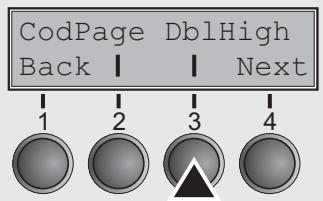

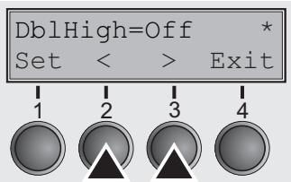
Horizontal pitch on Compress (IBMComp)
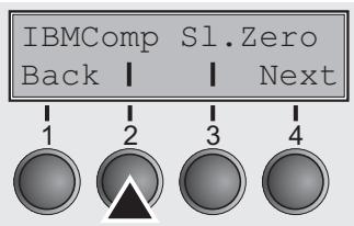
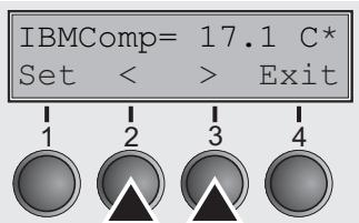
This option determines whether the IBM double height mode should be used (On) or not (Off).
Press the DblHigh key (3).
Setting options: On/Off
Default setting: Off
If the parameter On is selected, all data will be printed in double height.
If the parameter Off is selected, all data will be printed in normal height.
Confirm the setting by pressing the Set (1) key. Change to the next parameter group with the Next key (4).
This option selects the character density when receiving the Compress command (SI or ESC SI).
Press the IBMComp key (2).
Setting options: 17.1, 20 CPI
Default setting: 17.1 CPI
Confirm the setting by pressing the Set (1) key.
Slashed Zero (SI.Zero)
This option selects whether the zero character is printed with or without a slash.
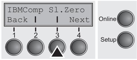
Press the SI.Zero key (3).
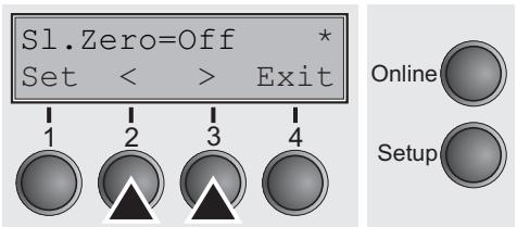
Setting options: On/Off
Default setting: Off
Confirm the setting by pressing the Set (1) key. Change to the next parameter group with the Next key (4).
Setting the EPSON Mode (EPSMode)
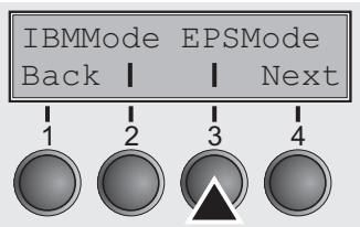
Horizontal spacing of characters (CPI)
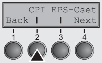
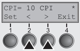
EPSON character set (EPS-Cset)
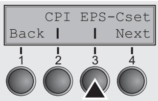
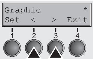
The EPSON mode option sets the EPSON protocol specific features.
Press the EPSMode key (3).
Sets the horizontal spacing of the printed characters used with the EPSON protocol.
Press the CPI key (2).
Setting options: 5, 6, 7.5, 8.6, 10, 12, 15, 17.1, 20 cpi and Proportional Spacing
Default setting: 10
Confirm the setting by pressing the Set (1) key.
This option defines the style which is applied to the character set.
Press the EPS-Cset key (3).
Setting options: Graphic, Italic, DLL
Default setting: Graphic
Graphic: The character sets are not altered.
Italic: The Italic style is applied to the character set.
DLL: A DLL (download) character set, as defined before, can be activated in the code range from hex. A0 to hex. FE.
Confirm the setting by pressing the Set (1) key. Change to the next parameter group with the Next key (4).
Code Page (CodPage)
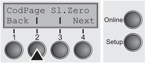
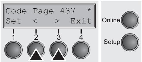
This option determines which code page the printer uses in EPSON mode.
Press the CodPage key (3).
Setting options: see table below
Default setting: Code Page 437
| CPI 210 | ISO Latin-2 Su | Code Page 852 |
| US ASCII | ISO Latin-Greek | Code Page 853 |
| British | ISO Latin-Hebr. Su | Code Page 855 |
| DEC Finnish | ISO Latin-Cyr. Sup | Code Page 857 |
| French | ISO Latin-5 Su | Code Page 858 |
| DEC French-Can. | ISO Latin-9 Su | Code Page 860 |
| German | E-USA | Code Page 861 |
| ISO Italian | E-France | Code Page 862 |
| JIS Roman | E-Germany | Code Page 863 |
| DEC Norw./Dan. | E-United Kingd | Code Page 864 |
| ISO Spanish | E-Denmark 1 | Code Page 865 |
| DEC Swedish | E-Sweden | Code Page 866 |
| Norw./Danish | E-Italy | Code Page 869 |
| DEC Dutch | E-Spain 1 | Abicomp |
| DEC Swiss | E-Japan | Brazilian ASCII |
| DEC Portuguese | E-Norway | Mazowan |
| Legal | E-Denmark 2 | Code MJK |
| DEC Supplement | E-Spain 2 | Bulgarian |
| DEC Spec.Graph. | E-L. America | ISO 8859-7 |
| DEC Technical | E-Turkey | ISO 8859-15 |
| DEC 7Bit Hebrew | E-Korea | ISO Latin 1T |
| DEC Hebrew Sup. | E-Legal | New Hebrew |
| DEC Greek Sup. | E-Old Hebrew | D-Hebrew |
| DEC 7Bit Turk. | Code Page 437 | Code Page 210 |
| DEC Turk. Sup. | CP 437 Greek | Code Page 220 |
| JIS Katakana | Code Page 850 | |
| ISO Latin-1 Su | Code Page 851 |
Confirm the setting by pressing the Set (1) key.
Slashed Zero (SI.Zero)
This option selects whether the zero character is printed with or without a slash.
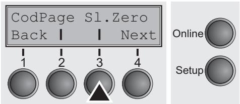
Press the SI.Zero key (3).
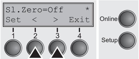
Setting options: On/Off
Default setting: Off
Confirm the setting by pressing the Set (1) key. Change to the next parameter group with the Next key (4).
Menu settings (example)
| Macro 1 * | Macro 2 | Macro 3 | Macro 4 | Current | |
| Protocol | |||||
| Parall. | EPSON ESC/P2 | IBM XL24E | EPSON ESC/P2 | IBM XL24E | EPSON ESC/P2 |
| Serial | DEC PPL2 | DEC PPL2 | DEC PPL2 | DEC PPL2 | DEC PPL2 |
| Font | Draft | Draft | Draft | Draft | Draft |
| LPI | 6 LPI | 6 LPI | 6 LPI | 6 LPI | 6 LPI |
| Single | * | * | |||
| Formlen | DIN A4 (297 mm) | Letter | 11" | Executive 10.5" | Letter |
| Head | 18 | 18 | 18 | 18 | 18 |
| FormAdj | 0/72" | 0/72" | 0/72" | 0/72" | 0/72" |
| Frontl | * | * | |||
| Formlen | Letter | Letter | 11" | Letter | 11" |
| Head | 18 | 18 | 18 | 18 | 18 |
| FormAdj | 12/72" | 12/72" | 12/72" | 12/72" | 12/72" |
| Width | 13.6Inch | 13.6Inch | 13.6Inch | 13.6Inch | 13.6Inch |
| Toprg | 1 | 1 | 1 | 1 | 1 |
| Botarg | 66 | 66 | 66 | 66 | 66 |
| Leftarg | 0/10" | 0/10" | 0/10" | 0/10" | 0/10" |
| PrinDir | Bidir | Bidir | Bidir | Bidir | Bidir |
| Auto-CR | On | On | On | On | On |
| Auto-LF | Off | Off | Off | Off | Off |
| PFmode | Off | Off | Off | Off | Off |
| Rightzo | Off | Off | Off | Off | Off |
| Leftzon | Off | Off | Off | Off | Off |
| Head up | Off | Off | Off | Off | Off |
| AGA | On | On | On | On | On |
| AGA offset | 0 | 0 | 0 | 0 | 0 |
| Hvy Form | Off | Off | Off | Off | Off |
| TearView | Year=ls | Year=ls | Year=ls | Year=ls | Year=ls |
| ESCChar | ESC | ESC | ESC | ESC | ESC |
| Barcode | Off | Off | Off | Off | Off |
| Barnode | Secured | Secured | Secured | Secured | Secured |
| DECHode | |||||
| CPI | 10 CPI | 10 CPI | 10 CPI | 10 CPI | 10 CPI |
| Country | US ASCII | US ASCII | US ASCII | US ASCII | US ASCII |
| UserChr | DEC Supplement | DEC Supplement | DEC Supplement | DEC Supplement | DEC Supplement |
| Wrap | On | On | On | On | On |
| Prn.ID | PPL2 | PPL2 | PPL2 | PPL2 | PPL2 |
| CAN Fkt. | Abort Sequ. | Abort Sequ. | Abort Sequ. | Abort Sequ. | Abort Sequ. |
| Discnt | Disable | Disable | Disable | Disable | Disable |
| Report | Disable | Disable | Disable | Disable | Disable |
| Answbck | Disable | Disable | Disable | Disable | Disable |
| Answ ENQ | Disable | Disable | Disable | Disable | Disable |
| IMMMode | |||||
| CPI | 10 CPI | 10 CPI | 10 CPI | 10 CPI | 10 CPI |
| CharSet | Standard | Standard | Standard | Standard | Standard |
| CodPage | Code Page 437 | Code Page 437 | Code Page 437 | Code Page 437 | Code Page 437 |
| Db1High | Off | Off | Off | Off | Off |
| IBMComp | 17.1 CPI | 17.1 CPI | 17.1 CPI | 17.1 CPI | 17.1 CPI |
| Sl.Zero | Off | Off | Off | Off | Off |
| EPSMode | |||||
| CPI | 10 CPI | 10 CPI | 10 CPI | 10 CPI | 10 CPI |
| CodPage | Code Page 437 | Code Page 437 | Code Page 437 | Code Page 437 | Code Page 437 |
| Eps-Cset | Graphic | Graphic | Graphic | Graphic | Graphic |
| Sl.Zero | Off | Off | Off | Off | Off |
| Interface Power-On Value | Options | Power-On Value | Options | Power-On Value | |
| Interf. | Auto | PMS | On | AutoASF | Off |
| Timeout | 2 sec | Quiet | Off | AutoTEA | Off |
| Buffer | 128 KB | Pap/back | normal | Single | On |
| CX-bid | On | Sound | On | Language | English |
| Baud | 9600 | Pagewid | 136/10" | Menu Locked | Off |
| Format | 8Bit No 1Stop | ||||
| BuffCtrl | XON/XOFF | ||||
| DTR | DTR | ||||
| TearAdj Front1 | 0/72" | ||||

Advanced menu
The advanced menu consists of test functions and advanced settings.
Test functions
Various tests to check proper operation of the printer are available at any time. With these tests it is possible to check the print quality, proper operation of the print head and the mechanics, as well as efficient data transmission from the computer to the printer.
The extended menu contains three test functions (ASCII 80, ASCII 136, H-Dump).
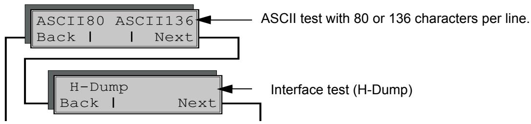
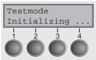
Enter advanced menu mode by pressing the key Online while switching on the printer and keep the key pressed until Testmode appears on the display.
The display shows Test mode for approx. 1 second and then automatically changes to display ASCII 80 ASCII 136.
Printer self-test (Rolling ASCII)
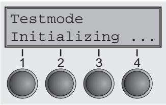
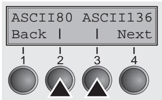
To check operational readiness, your printer contains a self-test routine which allows testing of the printer configuration, the print quality and correct operation of your printer.
Before performing a self-test, your printer must be switched off. Ensure that paper is inserted. Keep the key Online pressed while switching on the printer, until Testmode appears on the display.
Press the soft key for the ASCII 80 format (corresponds to Legal Portrait) or for ASCII 136 (Double or Legal Landscape). The display will indicate Test mode Off.
Press the Online key, to start the test.
It is also possible to change to Setup mode when you are in Rolling test mode if you want to change the configuration for the test printout.
To do this, press the key Setup. The printer then changes to Setup mode and the first of the main levels is then displayed.
Program your printer in the usual way for the test printout to change the parameters. See section Programming via the control panel (page 45).
Some changes in menu mode may cause the printer to reinitialize; in this case the Rolling ASCII test is aborted.

By pressing the key Setup you exit Setup mode and the printer once again returns to Rolling ASCII test mode test mode.
Testmode Off is displayed. Press the key Online, the test printout starts.
The self-test can be interrupted by pressing the key Online which will stop printing and put the printer into Offline status.
Before you begin printing, you can adjust the paper for the printout with soft keys and .
3456789:;<=>?@ABCDEFGHIJKLMNOPQRSTUVWXYZ[\]^
456789:;<=>?@ABCDEFGHIJKLMNOPQRSTUVWXYZ[\]
56789:;<=>?@ABCDEFGHIJKLMNOPQRSTUVWXYZ[\
6789:;<=>?@ABCDEFGHIJKLMNOPQRSTUVWXYZ[
789:;<=>?@ABCDEFGHIJKLMNOPQRSTUVWXYZ
89:;<=>?@ABCDEFGHIJKLMNOPQRSTUVWXYZ
9:;<=>?@ABCDEFGHIJKLMNOPQRSTUVWXYZ
;;<=>?@ABCDEFGHIJKLMNOPQRSTUVWXYZ
Example of an ASCII test printout
If you selected a proportional font (PS font), the printed length of the lines varies.
This test can also be used to determine and set the optimal print head gap (see the section Setting the print head gap (page 43).
Exiting Rolling ASCII test mode
The self-Rolling ASCII test mode test mode can only be terminated by switching off your printer. For this operation the printer must be Offline.
If you want to stop the test printout before switching off the printer, press the key Online.
Interface test (H-Dump)
With the interface test (Hex-Dump/H-Dump) you can test data transmission from the computer to the printer. During this test, the data from the computer is printed out in two columns. The text in the left column is printed in hexadecimal format and in the right column in ASCII format.
Printout in Hex-Dump
Put the printer into advanced menu mode by pressing the key Online while switching on the printer.

Press the key Online until Test mode is shown on the display.
The display shows Test mode for approx. 1 second and then automatically changes to display ASCII 80 ASCII 136.
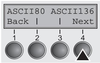
Press the key Next (4), the display shows the next menu level.
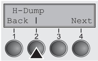
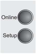
If you press the key H-Dump (2) you select the H-Dump mode and Offline H-Dump is shown on the display.
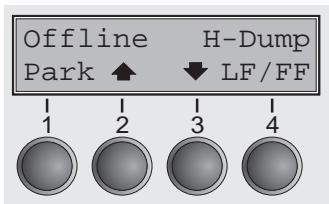
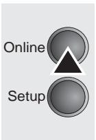
Put the printer into Online H-Dump mode by pressing the key Online. The printer is now ready to receive data from the computer and to print it out in hexadecimal format. The printed data can now be analyzed and evaluated.
| 1B | 5B | 36 | 7E | 1B | 5B | [6~].[ | ||||||||||
| 3F | 36 | 7E | 1B | 74 | 01 | 1B | 36 | 1B | 28 | 72 | 1B | 5B | 31 | 31 | 68 | ?6~.t..6.(r.[11h |
| 1B | 5B | 30 | 3B | 30 | 20 | 44 | 1B | 5B | 31 | 3B | 31 | 20 | 44 | 1B | 5B | . [0;0.D.[1;1.D.[ |
| 32 | 3B | 32 | 20 | 44 | 1B | 5B | 33 | 3B | 33 | 20 | 44 | 1B | 5B | 34 | 3B | 2;2.D.[3;3.D.[4; |
| 34 | 20 | 44 | 1B | 5B | 35 | 3B | 35 | 20 | 44 | 1B | 5B | 36 | 3B | 36 | 20 | 4.D.[5;5.D.[6;6, |
| 44 | 1B | 5B | 3F | 35 | 32 | 68 | 1B | 5B | 35 | 3B | 3B | 30 | 7B | 1B | 32 | D.[?52h.[5;04.2 |
| 1B | 5B | 38 | 34 | 31 | 38 | 74 | 1B | 5B | 37 | 32 | 38 | 20 | 68 | 0A | 1B | . [8418t.[728.h.. |
| 5B | 31 | 32 | 30 | 20 | 68 | 1B | 5B | 37 | 31 | 32 | 60 | 1B | 5B | 31 | 30 | [120.h.[712'.110 |
| 6D | 1B | 5B | 34 | 79 | 1B | 5B | 34 | 77 | 54 | 68 | 69 | 73 | 20 | 69 | 73 | m.[4y.[4wThis.is |
| 20 | 61 | 20 | 73 | 61 | 6D | 70 | 6C | 65 | 20 | 74 | 65 | 78 | 74 | 20 | 73 | .a.sample.text.s |
| 68 | 6F | 77 | 69 | 6E | 67 | 20 | 74 | 68 | 65 | 20 | 66 | 75 | 6E | 63 | 74 | howing.the funct |
| 69 | 6F | 6E | 61 | 6C | 69 | 74 | 79 | 20 | 6F | 66 | 20 | 74 | 68 | 65 | 20 | ionality.of.the. |
| 68 | 65 | 78 | 2D | 64 | 75 | 6D | 70 | 20 | 0D | 1B | 5B | 31 | 32 | 30 | 20 | hex-dump...[120, |
| 68 | 0A | 1B | 5B | 31 | 32 | 30 | 20 | 68 | 1B | 5B | 37 | 31 | 32 | 60 | 66 | h..[120.h.[712'f |
| 65 | 61 | 74 | 75 | 72 | 65 | 2E | 20 | 69 | 74 | 20 | 69 | 73 | 20 | 69 | 6E | eature..it.is.in |
| 74 | 65 | 6E | 64 | 65 | 64 | 20 | 74 | 6F | 20 | 61 | 6E | 61 | 6C | 79 | 73 | tended.to.analys |
| 65 | 20 | 74 | 68 | 65 | 20 | 69 | 6E | 63 | 6F | 6D | 69 | 6E | 67 | 20 | 64 | e.the.incomng.d |
| 61 | 74 | 61 | 20 | 73 | 74 | 72 | 65 | 61 | 6D | 2E | 20 | 20 | 0C | 1B | 5B | ata.stream....[ |
| 35 | 34 | 7B | 1B | 5B | 36 | 7E | 54{.}6 |
Example of a Hex-Dump printout

After the transmission you must switch the printer to Offline. Any remaining data left in the interface buffer is then printed.
Terminating Hex-Dump

Hex-Dump mode can only be terminated by switching off the printer.
If you want to stop the Hex-Dump printout before switching off the printer, press the key Online and then the key LF/FF (4) once.
Advanced settings
In the advanced menu, there are two other settings available besides the test functions.
The Single option can be used to deactivate the single sheet function (for printers without single sheet feeder).
The function Pap.back allows printing on paper with a dark back.

Enter Extended menu mode by pressing the key Online while switching on the printer and keep the key pressed until Testmode appears on the display.
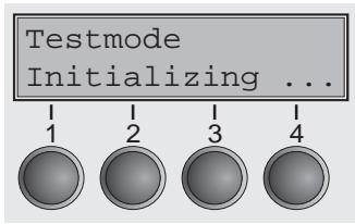
The display shows Test mode for approx. 1 second and then automatically changes to display ASCII 80 ASCII 136.
Deactivate single sheet feeder (Single)
Some printer models are designed for fanfold paper operation only and therefore do not feature a single sheet feeder. To prevent erroneous selection of the single sheet paper source, all sequences referring to the single sheet feeder can be deactivated by setting the Single menu option to Off.
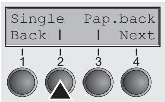

Select the Single (2) menu.
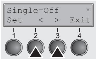
Setting options: On/Off Default setting: On
Single = On is the default setting for printer models with single sheet function.
Single = Off must be selected for printer models without single sheet function.

This setting is not reset by loading the default factory settings.
Confirm your settings by pressing the Set key (1).
Settings for paper with dark back (Pap.back)
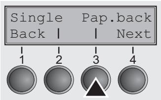
Select the Pap.back (3) menu.
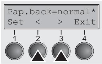
Setting options: normal/dark Default setting: normal
Pap.back = normal is the standard for normal paper.
Pap.back = dark can be set to process paper with a gray back.
Paper with a completely black back side cannot be used if the ink is carbon-based. However, the printer can handle aniline-based black paper (undefined colors).
Confirm the setting by pressing the Set (1) key. Change to the next parameter group with the Next key (4).
10 Troubleshooting
Many of the faults and problems which may occur while using the printer are minor problems which you can solve yourself. The following chapter should help you to distinguish between a simple operating error and a major malfunction.
This chapter provides information on the rectification of faults without the assistance of specially trained personnel. Follow the advice and tips in this chapter if your printer is not working correctly.
Important notes on the care and maintenance of your printer can be found at the end of this chapter.

Repairs should only be performed by authorised service personnel.
General print problems
| Problem | Corrective action |
| The display remains dark The printer is switched on, but nothing happens (nothing is displayed, no noise). | Switch off the printer and proceed as follows: 1 Check that the power plug is correctly connected to the socket on the printer. 2 Check that the power plug is seated properly in the wall socket. 3 Switch on the printer again. If the printer is now connected correctly, the printer initializes and text is shown on the display. If these steps do not eliminate the fault: ► Replace the power cord and repeat step 3. ► Check whether the fuse is faulty and if so exchange it.:, see Replacing the fuse (page 116). ► Check that power flows at the socket e.g. using a desk lamp, if necessary use a different socket and repeat step 3. ► Contact your dealer if the printer cannot be powered up. STOP Do not attempt to open the printer. You might suffer an electric shock. |
| The display is lit, but the printer does not print | 1 Check that the printer is Online. If the displays shows Offline, then press the key Online. Try to print again. 2 Check the connection from the printer to the computer (interface cable): ► Check that the interface cable is properly connected to the computer and to the printer. ► Check that it is the correct interface cable for your printer. Information on the interface is located in the section Connecting the printer (page 8) and in chapter Interfaces (page 133). ► Check that the printer is properly adapted to the computer (configured). Refer to section The control panel (page 26). Check the parameter set in the Setup menu under Settings for interfaces (I/O) (page 57)and if necessary correct it. 3 Check whether the printer is working properly. To do this, print out a copy of the menu; siehe Printing out macro configurations (Print) (page 51) 4 Check that the top cover is closed. 5 Check that paper is inserted and loaded. Refer to the section Loading paper (page 34) |
| Problems with the paper feed The paper is not fed in | 1 Check that the display shows the correct paperway, if necessary select the correct paperway (single sheet or fanfold) with the key Park. See Changing the paper path (page 32). If you wish to use optional paper types, make sure they are correctly installed. 2 Make sure that the paper guide is correctly adjusted at the side. 3 When using single sheets, push the paper fully into the paper feed. When having torn off the fanfold paper and after switching over from fanfold paper to single sheets, the fanfold paper moves to the park position. 4 Check that the fanfold paper is in the park position when you insert a single sheet. This means the fanfold paper should not be loaded (pulled in). To check this, raise the guide of the single sheet feeder. If necessary, drive the remaining paper manually to the park position with the ↓ key. |
| Paper jam (fanfold paper) | 1 Open the top cover. If a paper jam should occur, then remove the jammed paper by tearing it off at the tear off edge (the tear off edge is located at the outfeed for the fanfold paper). 2 Press the ↓ key to transport the paper backwards. 3 You may support the paper return feed by cautiously pulling the paper in the correct direction. Before you replace the fanfold paper, refer to the instructions in the section Loading paper (page 34). You should pay special attention to the following points: ► Insert the paper straight. ► After inserting the paper, close the tractors. ► Adjust the tractors, the paper should be positioned in the tractors straight but without tension. ► Adjust the print head gap to the paper thickness (if AGA=Off). ► Set the parameter Head-up to On, see section Increasing the print head gap (Head up) (page 78). ► Clean upper friction, see section Cleaning the upper friction (page 118). |
| Paper jam (single sheets) | Open the top cover and remove the paper manually or with the functions LF (line feed)/FF (form feed) in Offline mode from the printer. Before you replace the single sheet, refer to the instructions in the section Single sheets (page 36). Pay attention to the following points: ► Set single sheet feed to the corresponding paper width. ► Insert the paper straight as far as possible. ► Adjust the print head gap to the paper thickness (card-like paper etc.) (if AGA=Off). |
| Paper does not move to tear off position Single sheet inserted | It is only possible to tear off when fanfold paper is used, refer to the section Moving the paper to the tear position (page 39). |
Problems with the print quality
| Problem | Corrective action |
| Print is too pale | 1 The ribbon is used up or the ribbon cassette is not correctly fit-ted. Refer to the section Inserting the ribbon cassette (page 10).2 The print head to platen gap is not correctly set, refer to the sec-tion Setting the print head gap (page 43).3 For printers with the AGA = ON: Enter a correction value <0.See the section Setting the print head gap (page 43). |
| Smudged print | 1 The ribbon is damaged (e.g. frayed). Change the ribbon as de-scribed in the section Inserting the ribbon cassette (page 10).2 The print head gap is too small, increase the gap. See the sec-tion Setting the print head gap (page 43).3 For printers with AGA = ON: Enter a correction value >0 (cor-reaction value 0 to +10). See the section Setting the print head gap (page 43). |
| Prints undefined characters | 1 Check that the interface plug is correctly connected to the com-puter and to the printer.2 Check that the proper emulation and the correct character set (country, CG table or character set) is selected in the Setup menu.3 Check the length of the interface cable, see section Interface specifications (page 123).4 Set CX-bid in the advanced menu to Off, see sectionBidirectional parallel interface (CX-bid) (page 80).5 Check that the printer is properly adapted to the computer (con-figured). Refer to section The control panel (page 26). Check the parameter set in the Setup menu under Settings for inter-faces (I/O) (page 57)and if necessary correct it. |
| The first line is not completely printed out at the top | Check the function FormAdj. Refer to the section First printing position (FormAdj) (page 69). |
| Dots within characters are missing | 1 Check whether the ribbon is damaged, if necessary replace it.See the section Inserting the ribbon cassette (page 10).2 Set the correct print head gap.3 Check whether the platen is damaged.4 Check whether the print head is damaged.We recommend to use genuine ribbon cassettes only. In case of points 3 or 4, please contact your dealer. |
Error messages via the display
| Message | Possible cause | Corrective action |
| Eject Error | The printer cannot eject the paper or cannot place the paper in the park position. | Check the following: ► Whether the paper path is blocked by a foreign object. ► Whether the paper is damaged. ► Whether the upper friction is down and clicked into place. ► Whether the print head gap is too small; see section Setting the print head gap (page 43). |
| Load Error | The printer cannot feed in the loaded paper. | Check the following: ► Whether the paper path is blocked by a foreign object. ► Whether the paper is damaged. ► Whether the tractors are closed and locked. ► Whether the paper is too tight or loose. ► Whether the paper is within the specified range. Details see section Loading paper (page 34) |
| Load paper from ... alternating with | The paper has run out during operation. 1 Printer is switched on but no paper is loaded in the displayed (active) paper compartment. | ► Insert paper in the active sheet feeder. |
| Printing | 2 The paper is not fed past the light barrier. | ► Place the paper more to the left. If the display shows Online or Offline instead of Print, the printer has loaded no paper and there is no print job. It is no error message in this case, actions are not required. |
| Paper Jam | Paper jam. | Eliminate the paper jam detected by the paper motion sensor. For the procedure, see Paper jam (fanfold paper) (page 109) or Paper jam (single sheets) (page 110). Paper is too narrow. Use paper with a width of at least 6.3" (16 cm) if the PMS function is enabled. See Automatic paper motion sensor (PMS) (page 76) |
| Cover open | Top cover is open. | Close the top cover. |
| Hardware Alarm | Internal hardware error. | Try switching off and on. Check if changes to options have been previously carried out. Note down the display message. Contact your dealer. |
| Parity Error | Transmission error from computer to printer via the optional serial interface. | Compare the interface configuration of your printer with the settings of your computer (protocol), see Interfaces (page 133). Check the cable, if necessary replace it. The cable exceeds the maximum allowed length, see Interface specifications (page 123). |
| Frame Error | Transmission error (serial interface). | Compare the format setting of your printer with the setting of your computer. Check the permissible cable length, see Interface specifications (page 123). See parity error. |
| Overrun Error | Received data which has not yet been printed is overwritten with new data. | Check that the correct busy pro-tocol (e.g. XON XOFF) is set in the menu Serial interface, pro-tocol, see Protocols (page 139).Check the interface cable, see section Connecting the printer (page 8) and Interfaces (page 133). |
| Paperwidth ErrorPress Online | A print job exceeds the paper width with the automatic paper width detection active. | Cancel the print job or load sui-table paper, see also Automatic paper width detection (APW) (page 82).If this message appears although the loaded paper is wide enough, consult the technical service. |
| Head Hot | The printer prints at lower speed. | No action required.When this message comes up even in a "cold" printer, please contact your technical service. |
| Check Ribbon | The ribbon misses, is damaged and blocked or a non-genuine rib-bon is installed. | Only use genuine ribbon cas-settes of the manufacturerSTOPDuring the process of ini-tialization after powering on, the printer checks if a ribbon cassette is installed. It also checks during the execution of a print job the operativ-ness of the ribbon cas-sette.These functions mandatory require the use of the manufacturers original ribbon cassettesAccessories (page 143).Replace the ribbon.Recheck that the print head carria-ge moves easily. |
Additional display messages
These are not error messages, they give operating instructions and information from the printer to the user.
| Message | Possible cause | Corrective action |
| Press any key | — | To proceed press any key. |
| Loading Default | The factory-set parameters are loaded and are written into all menus. | No action required. |
| Only available in Epic Mode | Functions which have no meaning in this emulation have been selec-ted. | For this function please switch to the appropriate emulation in the menu, see Selecting Proto-col (emulation) (page 55). |
| Park position | You are informed when the fanfold paper is in the park position. | No action required. |
| Tear paper off | Note for the operator to tear off the paper automatically positioned at the tear off edge. | Tear paper off. |
| Load paper from ... | Paper is not available in the selec-ted paper path (... indicates the active paper path). Data is in the interface receiver buffer. | Load paper, see section Loading paper (page 34) |

If messages appear which are not described here, please contact your customer service representative with exact details of the message.

Care and maintenance
The printer is designed to operate with minimal maintenance. It is advisable to clean the inside of the printer from time to time with a vacuum cleaner.

Before cleaning, turn off the printer, wait 5 to 10 seconds and disconnect the power cable.

Do not oil or grease the printer, especially the sliders and shafts.
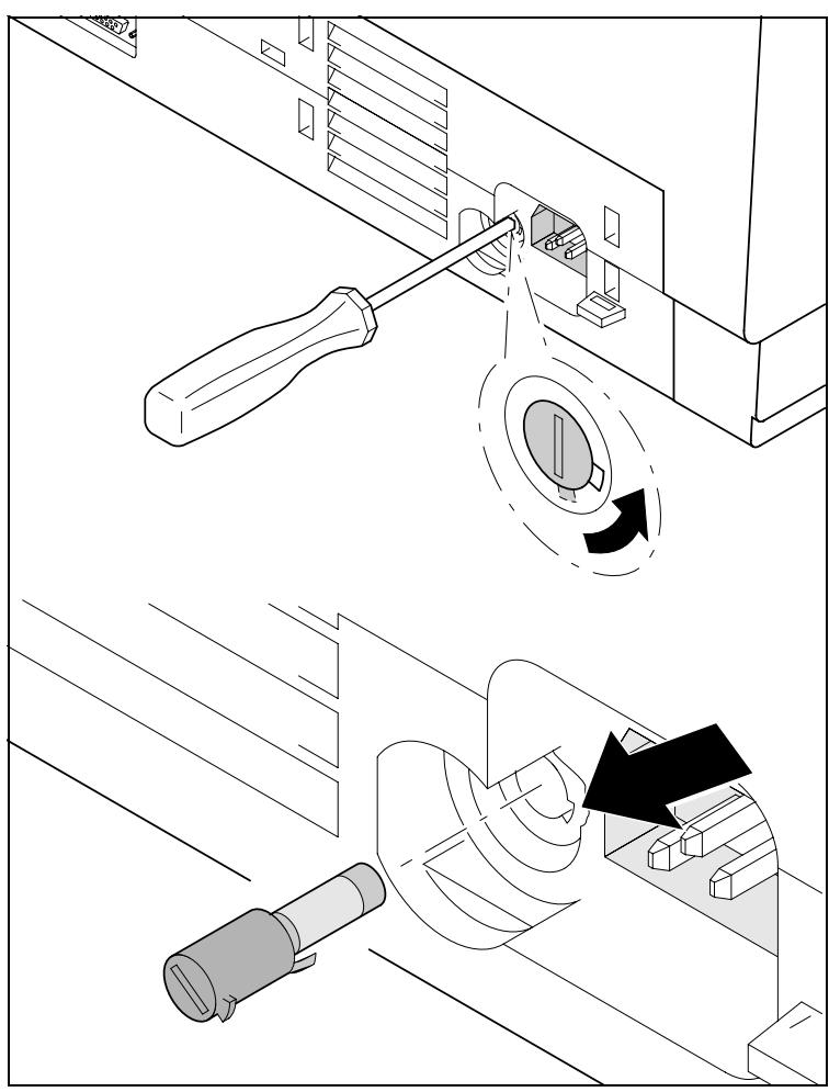
Replacing the fuse
The printer is provided with a line fuse accessible from the exterior. Press the fuse cover slightly inwards with a screwdriver and turn it until the cover tab comes out through the recess in housing. Then remove the fuse.
Install the fuse in reverse order of steps.

Only use the same type of fuse for replacement.
The fuse ratings are specified on the printer type plate which is mounted above the power connector on the rear:
T4,00AH250V
Cleaning the housing
Clean the printer housing with mild detergent (use a dishwashing agent, if necessary, or a plastic cleaning agent) and a soft lint-free cloth.

Do not use abrasive cleaners. Never use solvents.
Cleaning the interior
Remove paper and dust with a soft brush.
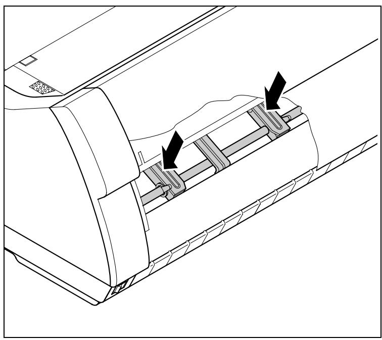
Check that any paper has been removed from the tractors.

For optimal function of the print head the interior of the printer has to be as dust free as possible. Clean the interior with a vacuum cleaner if necessary.
Cleaning the platen

Remove the ribbon. Clean the printer bar cautiously with an alcohol-based cleaning agent.
Remove dustcarefully from the platen.

Avoid touching parts and components in the printer interior.
Ribbon
Check whether the ribbon is worn or damaged. The ribbon must be replaced if it is frayed, see Inserting the ribbon cassette (page 10) and Error messages via the display (page 112).
Cleaning the upper friction
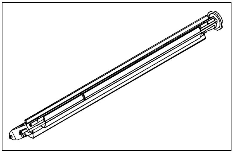
Clean the rollers of the upper friction as necessary with a mild cleaning agent and a soft, lint-free cloth.

Avoid touching the pin rollers.
Carriage shafts

Carriage shafts must not be oiled or greased; otherwise damage will occur on the printer.

Specifications
Printer specifications
| Printer system | Serial impact matrix printer print head with 24 needles, ∅ 0.25 mm bidirectional printing | |||||
| Print speed and character matrices | LA650+ | LA800+ | ||||
| CPS | CPI | matrix | CPS | CPI | matrix | |
| HSQ (High Speed Quality) | 650 | 10,0 | 12 x 10 | 800 | 10,0 | 12 x 10 |
| 720 | 12,0 | 12 x 10 | 800 | 12,0 | 12 x 10 | |
| 900 | 15,0 | 08 x 08* | 1000 | 15,0 | 08 x 08* | |
| 900 | 15,0 | 12 x 08 | 1000 | 15,0 | 12 x 08 | |
| 515 | 17,1 | 12 x 12 | 571 | 17,1 | 12 x 12 | |
| 600 | 20,0 | 12 x 10 | 667 | 20,0 | 12 x 10 | |
| DPQ (Data Print Quality) | 600 | 10,0 | 12 x 12 | 667 | 10,0 | 12 x 12 |
| 720 | 12,0 | 12 x 10 | 800 | 12,0 | 12 x 10 | |
| 900 | 15,0 | 08 x 08* | 1000 | 15,0 | 08 x 08* | |
| 900 | 15,0 | 12 x 08 | 1000 | 13,0 | 12 x 08 | |
| 515 | 17,1 | 12 x 12 | 571 | 17,1 | 12 x 12 | |
| 600 | 20,0 | 12 x 10 | 667 | 20,0 | 12 x 10 | |
| CPQ (Copy Print Quality) | 300 | 10,0 | 24 x 12 | 333 | 10,0 | 24 x 12 |
| 360 | 12,0 | 24 x 10 | 400 | 12,0 | 24 x 10 | |
| 450 | 15,0 | 16 x 08* | 500 | 15,0 | 16 x 08* | |
| 450 | 15,0 | 24 x 08 | 500 | 15,0 | 24 x 08 | |
| 260 | 17,1 | 24 x 12 | 285 | 17,1 | 24 x 12 | |
| 300 | 20,0 | 24 x 10 | 333 | 20,0 | 24 x 10 | |
| NLQ (Near Letter Quality) | 200 | 10,0 | 24 x 18 | 222 | 10,0 | 24 x 18 |
| 240 | 12,0 | 24 x 15 | 267 | 12,0 | 24 x 15 | |
| 300 | 15,0 | 16 x 12* | 333 | 15,0 | 16 x 12* | |
| 150 | 15,0 | 24 x 18 | 167 | 15,0 | 24 x 18 | |
| 170 | 17,1 | 24 x 18 | 190 | 17,1 | 24 x 18 | |
| 200 | 20,0 | 24 x 15 | 222 | 20,0 | 24 x 15 | |
| LQ (Letter Quality) | 100 | 10,0 | 24 x 36 | 111 | 10,0 | 24 x 36 |
| 120 | 12,0 | 24 x 30 | 133 | 12,0 | 24 x 30 | |
| 150 | 15,0 | 16 x 24* | 167 | 15,0 | 16 x 24* | |
| 150 | 15,0 | 24 x 18 | 167 | 15,0 | 24 x 18 | |
| 170 | 17,1 | 24 x 18 | 190 | 17,1 | 24 x 18 | |
| 200 | 20,0 | 24 x 15 | 222 | 20,0 | ||
| * Epson emulation only: superscript, subscript, microscript | ||||||
| Tab speed | LA650+: 65 ips (inch per second) | LA800+: 80 ips (inch per second) |
| Print width | 136 characters at 10 cpi 163 characters at 12 cpi 204 characters at 15 cpi 232 characters at 17,1 cpi 272 characters at 20 cpi | |
| Character pitch | depends on the selected emulation, see Setting the DEC Mode (DECMode) (page 86), Setting the IBM mode (IBMMode) (page 92) and Setting the EPSON Mode (EPSMode) (page 96). | |
| Character size | ||
| Height | 3.32 mm (incl. descendants) | |
| Width | 2.19 mm, max. 2.43 mm | |
| Fonts | ||
| Standard | High Speed Draft, DPQ, Copy Draft; Courier, Roman, Sans Serif, OCR A + B, Gothic, Prestige, Orator, Souvenir (all resident in NLQ und LQ); DLL is standard | |
| Barcodes (Standard) | 18, see Barcode (page 132) | |
| Emulations | ||
| Standard | DEC PPL2 IBM Proprinter XL24E, IBM Proprinter XL24E+AGM EPSON ESC/P | |
| Optional | on request | |
| Resolution | 60 to 360 dpi horizontal | |
| 90 to 360 dpi vertical | ||
| Print attributes in all character pitches | Double width, italics, right justification, shadowed, auto centered, double height, bold, proportionally spaced, underlined, overlined, superscript, subscript, heavy form mode | |
| Self-test | ASCII-Test Hexdump Fault display Ribbon test | |
| Print buffer | 128 KB max. | |
| Panel | LCD display, 2 x 16 digits Online Setup 4 softkeys | |
| Noise | ||
| Sound pressure level | LA650+: LPA = ≤55 dB(A) in HS mode (ISO 7779[1988]) LA800+: LPA = ≤57 dB(A) in HS mode (ISO 7779[1988]) | |
| Sound power level | LA650+: LWAd = 72 dB(A) in HS mode (ISO 7779[1988]) LA800+: LWAd = 72 dB(A) in HS mode (ISO 7779[1988]) | |
| Continuous operation | LA650+ | LA800+ |
| Throughput (ECMA 132) | >40 000 pages/month (DPQ) | >50 000 pages/month (DPQ) |
| 540 pages/hour | 600 pages/hour | |
| MTBF | 10 000 h; 100% DC | 10 000 h; 100% DC |
| Mains voltage | USA/Canada: 120 V ±10%, 60 Hz ±2% | |
| Europe 230 V ±10%, 50/60 Hz ±2% | ||
| Power consumption | LA650+ at 100% throughput: 65 VA when idling: 20 VA | LA800+ at 100% throughput: 75 VA when idling: 24 VA |
| Approvals | ISO 60950, CE, GOST, VDE/GS+CB, cULus, FCC/B, CCC, Energy Star | |
| Dimensions | ||
| Width | 624 mm | |
| Height | 276 mm | |
| Depth | 430 mm | |
| Weight | 21 kg | |
| Paper feed | ||
| Feed speed | 10"/sec | |
| Feed first line | (6 lpi) 35 ms | |
| View position | 10"/sec | |
| Reverse motion | Up to max. form length (22 inch) max. 0.5 inch for automatic single sheet feeder | |
| Print head gap | ||
| Standard | Automatic gap adjustment | |
| Paper transport | ||
| Standard | Tractor with parking position | |
| Manual single sheet feeder, front insertion (friction rollers) | ||
| Optional | Tractor 2 (front) | |
| Service life | ||
| Print head | 500 mio. / DPQ, 12 x 12 matrix | |
| Ribbon | 20 mio. characters, DPQ | |
| Environmental conditions | ||
| Operation | ||
| Temperature | +10° to +35°C | |
| Rel. humidity | 15 to 75% | |
| Climate | IEC/EN 60721-3-3, class 3K2 | |
| Storage | ||
| Temperature | -5° to +45°C | |
| Rel. humidity | 5 to 95% | |
| Climate | IEC/EN 60721-3-1, class 1K3 | |
| Transport | ||
| Temperature | -20° to +60°C | |
| Rel. humidity | 5 to 95% | |
| Climate | IEC/EN 60721-3-2, class 2K2 | |
Interface specifications
| Parallel interface | bidirectional |
| Type of data transmission | 8-bit parallel interface (Centronics compatible) IEEE-1284; Nibble mode |
| Transmission rate | Max. 30 KHz |
| Signal status | Low: 0,0 V to +0,4 V |
| High: +2,4 V to +5,0 V | |
| Connection cable | Material: AWG 28 at least |
| Length: up to 2,0 m | |
| Twisted-pair cable with double-shield, acc. IEEE Std 1284 - 1294 | |
| Voltage supply of external devices on pin 18 | U = +5 V ±10% |
| I = 0,5 Amax | |
| Interface connections | Printer side: Amphenol 57-40360, 36-pin (or compatible) |
| Cable side: Amphenol 57-30360, 25-pin (or compatible) | |
| Ethernet interface | Onboard 10/100BaseT Ethernet-RJ45 with 2 LEDs |
| Transmission rate | 100 Mbps / Full Duplex |
| Supported protocoles | TCP/IP, Telnet |
| Network print protocoles | LPR/LPD, RAW Port, FTP |
| IP address designation | DHCP, BootP and manually over the control panel |
| Connection cable | RJ45 |
| Network print management protocoles | HTTP, HTML, SNMP |
| Capacity of data buffer | 8 MB |
| Serial interface | RS232C interface |
| Synchronization | Asynchronous |
| Transmission rate | 600 bauds to 19 200 bauds |
| Signal status | OFF = Mark = log.1 = -3 V to -15 V ON = Space = log. 0 = +3 V to +15 V |
| Connection cable | Length up to 15 m |
| Interface connections | ITT Cannon connector, series DB-25 S |
| Transmission protocol | XON/XOFF, ENQ/STX, READY/BUSY, Robust XON/XOFF, ETX/ACK |
| Capacity of data buffer | 1024 KB max. |
Paper specifications
| Continuous paper tractor 1, single part forms | Weight Width¹ Form length | 60 to 120 g/m² 76 to 420 mm 76 to 559 mm |
| Continuous paper Multi-part forms, tractor 1 (to be tested individually) | Copies LA650+ LA800+ | 1 + 6 1 + 5 |
| Weight of original | 45 to 65 g/m² | |
| Weight of copies | 45 to 56 g/m² | |
| Weight of bottom sheet | 45 to 65 g/m² | |
| Thickness (max.) | 0.6 mm | |
| Width¹ | 76 to 420 mm | |
| Form length | 76 to 451 mm | |
| Cut sheet insertion via front feed/manual single part forms | Weight | 80 to 120 g/m² |
| Width¹ | 76 to 420 mm | |
| Form length | 76 to 305 mm | |
| Envelopes | Width | 76 to 420 mm |
| Length | 76 to 305 mm | |
| Thickness | 0.32 mm | |
| Set of forms | Sets of forms may be used only if the top edge is bound. The binding edge should be as soft as possible. A wavy binding edge may amper the smooth feeding of these sets. Multi-part forms must be loaded with the bound top edge down. Multi-part forms should be tested for suitability. | |
| Paper quality | Light pulp paper of medium fine quality, paper bearing the quality mark SM Post and photocopy paper are suitable for use. Unsuitable are: satin-finish or coated papers, imitation art papers, and embossed papers. Since paper as natural material reacts strongly to environmental influences (e.g. humidity, temperature), the place of storage should be selected carefully. We recommend that this kind of paper should be tested extensively before larger quantities are acquired. Should papers with a dark reverse side be used, these should also be tested for their functionality. Please pay attention to the use of infrared reflec-ting colors, when acquiring these papers. | |
| 1 with PMS = Off, if PMS = On: 6.3" (160 mm) | ||

Available character sets and fonts
The following list includes all the character sets you can select from the control panel or via ESC sequences and specifies the fonts in which they are available.
The character sets are only available in the fonts marked with an X. They can be selected via the menu or by means of ESC (
| ID for ESC R/ESC( | Draft | Draft Copy | Roman | Sans Serif | Courier (incl. Courier IBM) | OCR-B | OCR-A | Prestige | Script | Orator | |
| ISO USA (ASCII) | 42 | X | X | X | X | X | X | X | X | X | X |
| ISO UK (British) | 41 | X | X | X | X | X | X | X | X | X | X |
| ISO France (French) | 52 | X | X | X | X | X | X | X | X | X | X |
| ISO Germany (German) | 4B | X | X | X | X | X | X | X | X | X | X |
| ISO Italy (Italian) | 59 | X | X | X | X | X | X | X | X | X | X |
| ISO Norway (Norw./Danish) | 60 | X | X | X | X | X | X | X | X | X | X |
| ISO Spain (Spanish) | 5A | X | X | X | X | X | X | X | X | X | X |
| ISO Portugal | 4C | X | X | X | X | X | X | X | X | X | X |
| Epson USA | 00 | X | X | X | X | X | X | X | X | X | X |
| Epson France | 01 | X | X | X | X | X | X | X | X | X | X |
| Epson Germany | 02 | X | X | X | X | X | X | X | X | X | X |
| Epson UK | 03 | X | X | X | X | X | X | X | X | X | X |
| Epson Denmark | 04 | X | X | X | X | X | X | X | X | X | X |
| Epson Sweden | 05 | X | X | X | X | X | X | X | X | X | X |
| Epson Italy | 06 | X | X | X | X | X | X | X | X | X | X |
| Epson Spain | 07 | X | X | X | X | X | X | X | X | X | X |
| Epson Japan | 08 | X | X | X | X | X | X | X | X | X | X |
| Epson Norway | 09 | X | X | X | X | X | X | X | X | X | X |
| EPson Denmark II | ||||||||||||||||||||||
| EPson Spain II | ||||||||||||||||||||||
| EPson Korea | ||||||||||||||||||||||
| EPson Legal | ||||||||||||||||||||||
| Epson Turkey | ||||||||||||||||||||||
| Epson Old Hebrew | ||||||||||||||||||||||
| Epson/IBM New Hebrew | ||||||||||||||||||||||
| Epson/IBM D-Hebrew | ||||||||||||||||||||||
| CP437 Latin US | ||||||||||||||||||||||
| CP850 Latin 1 | ||||||||||||||||||||||
| CP851 Greek | ||||||||||||||||||||||
| CP852 Eastern Europe | ||||||||||||||||||||||
| CP853 Turkish | ||||||||||||||||||||||
| CP855 Cyrillic | ||||||||||||||||||||||
| CP856 IBM with- | ||||||||||||||||||||||
| CP860 Portuguese | ||||||||||||||||||||||
| CP861 Icelandic | ||||||||||||||||||||||
| CP862 Hebrew | ||||||||||||||||||||||
| CP863 French Canada | ||||||||||||||||||||||
| CP864 Arabic | ||||||||||||||||||||||
| 86 | X | X | X | X | X | X | X | X | X | X | X | X | X | X | X | X | X | X | X | X | X | X |
| 86 | X | X | X | X | X | X | X | X | X | X | X | X | X | X | X | X | X | X | X | X | X | X |
| 86 | X | X | X | X | X | X | X | X | X | X | X | X | X | X | X | X | X | X | X | X | X | X |
| CP866 Russian | 8E | ID for ESC R/ESC ( |
| CP866 Bulgaria | ||
| Mazovia (Polish) | 92 | Draft |
| 8859-15 Latin 9 (Euro) | 2D | Draft Copy |
| Brazilian ASCII | 6D | Roman |
| Abicomp (Br. Portuguese) | 6E | Sans Serif |
| DEC ISO Latin-1 Suppl. | 63 | Courier (incl. Courier IBM) |
| DEC ISO Latin-2 Suppl. | B1 | OCR-B |
| DEC ISO Latin-Greek Supp. | B2 | OCR-A |
| DEC ISO Latin-Hebrew Supp. | B3 | Prestige |
| DEC ISO Latin-Cyrillic Supp. | B4 | Script |
| DEC ISO Latin-5 Suppl. | B5 | Orator |
| DEC ISO Latin-9 Suppl. | B6 | X |
| DEC Hebrew Supplemental | 3F | X |
| DEC 7-Bit-Hebrew | 44 | X |
| DEC Legal | 50 | X |
| DEC JS Katakana | 49 | X |
| DEC 8-Bit-Turkish | 53 | X |
| DEC 8-Bit-Greek Suppl. | 54 | X |
| DEC 8-Bit-Turkish Suppl. | 54 | X |
| DEC 8-Bit-Greek Suppl. | 54 | X |
| DEC 8-Bit-Turkish Suppl. | 54 | X |
| DEC 8-Bit-Greek Suppl. | 54 | X |
| DEC 8-Bit-Turkish Suppl. | 54 | X |
| DEC 8-Bit-Turkish Suppl. | 54 | X |
| DEC 8-Bit-Turkish Suppl. | 54 | X |
| DEC 8-Bit-Turkish Suppl. | 54 | X |
| DEC 8-Bit-Turkish Suppl. | 54 | X |
| DEC 8-Bit-Turkish Suppl. | 10 | X |
| ID for ESC R/ESC( | High Speed | Draft | Draft Copy | Roman | Sans Serif | Courier (incl. Courier IBM) | OCR-B | OCR-A | Prestige | Script | Orator | |
| DEC Finnish | 35 | X | X | X | X | X | X | X | X | X | X | X |
| DEC French-Canadian | 39 | X | X | X | X | X | X | X | X | X | X | X |
| DEC JIS Roman | 4A | X | X | X | X | X | X | X | X | X | X | X |
| DEC Norwegian/Danish | 36 | X | X | X | X | X | X | X | X | X | X | X |
| DEC Swedish | 37 | X | X | X | X | X | X | X | X | X | X | X |
| DEC Swiss | 3D | X | X | X | X | X | X | X | X | X | X | X |
| DEC Supplemental | 62 | X | X | X | X | X | X | X | X | X | X | X |
| DEC Technical | 3E | X | X | X | X | X | X | X | X | X | X | X |
| DEC Special Graphics | 30 | X | X | X | X | X | X | X | X | X | X | X |
| DEC Portuguese | 61 | X | X | X | X | X | X | X | X | X | X | X |
| CP437 Greek | A0 | X | X | X | X | X | X | X | X | X | X | X |
| Code MJK | A1 | X | X | X | X | X | X | X | X | X | X | X |
| CP210 | A2 | X | X | X | X | X | X | X | X | X | X | X |
| CP220 | A3 | X | X | X | X | X | X | X | X | X | X | X |

All codepages will be printed in all fonts, but the character shape may look the same although the font names are different. In IBM emulation only the codepages defined by ESC [ T ... are available.

DEC Technical: non-Greek characters are the same for all LQ fonts
Greek characters are the same in OCR-A and OCR-B
There are only two LQ fonts for cyrillic characters : Roman = Courier = Prestige = Script and Orator = SansSerif = OCR-A = OCR-B
- Arabic characters exist only in LQ 10 and 12 cpi, no Arabic Draft, Draft Copy and 15 cpi Epson style
Greek characters look the same for all LQ fonts
- Epson Turkey, Old Hebrew, New Hebrew and D-Hebrew have preliminary IDs and cannot be selected via the ESC (t ... command; but the code pages will be implemented and shown in the menu and can be selected via the menu or with the ESC R ... command.
- Codepages 210 and 220 cannot be selected with ESC ( t ... commands in Epson emulation, these commands are not defined, instead these codepages can be selected via the menu or with the ESC R ... command.
There is only one Draft- and one LQ-font for all Hebrew characters and for all Katakana characters.

Emulations
General
When a printer understands the control set written for another printer type, it is said to emulate the other printer. Your printer in its standard version emulates, i.e. "understands" the DEC-PPL2 for the serial interface and Epson ESC/P2 using the parallel interface.
Escape sequences
Escape sequences or control codes tell the printer that the following transmitted code is a printer command and not a printable character.
They allow the selection of printer functions or the changing of printer parameters from the computer. By transmitting an escape sequence, you are able to change the previously set configuration of the printer (e.g. character set).
This chapter contains an introduction into the sequences and control codes which are used by your printer.

The settings made by escape sequences have priority over the settings made in menu mode; therefore they override these.
What are escape sequences?
An escape sequence consists of an ESCape control character (ESC = decimal 27 or hexadecimal 1B) followed by one or more characters, which represent commands to the printer. Please note that this escape character has nothing to do with the ESC key on your computer keyboard.
For example, the control character ESC followed by the character "4" tells your printer to print the subsequent text in italics.
How are escape sequences used?
Escape sequences are transmitted to the printer by your computer software via the printer driver. Experienced users and programmers can also control the printer directly via control sequences, however before you start working with escape sequences and control codes, we recommend that you study the computer software manual.
To enter control codes the Ctrl key and an ASCII character must be pressed simultaneously. For instance, by pressing Ctrl and J a line feed is accomplished (it is required to output the character string on the printer). More information concerning this topic is contained in your computer software manual and the corresponding Programmer's Application Manuals (see section Programming manuals, page 143).

For details on the escape sequences in the DEC, EPSON and IBM emulation refer to the Programmer's Manual on this CD-ROM.
Barcode
Even the standard version of your printer has the possibility of using up to 18 different barcode types.

Barcode mode can be accessed in DEC emulation. The user can decide whether barcode is activated permanently or activated depending on the situation by means of an escape sequence.
List of available barcodes
| Type | Barcode | Type | Barcode |
| 0, 2 | Code 3 of 9 | 11 | UPC-A |
| 1 | Interleaved 2 of 5 | 12 | UPC-E |
| 4 | EAN 8 | 13 | Postnet |
| 5 | EAN 13 | 14 | Industrial 2 of 5 |
| 7 | Codabar a/t | 15 | not supported |
| 8 | Codabar b/n | 16 | MSI mod 10/10 |
| 9 | Codabar c/* | 17 | Code 128 (EAN 128) |
| 10 | Codabar d/e | 18 | Matrix 2 of 5 |

Please note that within the Barcode environment the barcode commands have priority in case of conflicts with the emulation.

Additional information is provided in the Programmer's Manual on this CD-ROM.

Interfaces
Your printer offers the possibility of operating via a parallel, an Ethernet or a serial interface. This chapter informs you about the parallel Centronics compatible interface, the Ethernet interface and the serial interface type RS232C/V.24 and describes the communication between your computer and the printer.
These interfaces are linked to form a so-called shared interface. Your printer can be configured to use only one interface or both alternately. When only one interface is used, it is monitored by the printer. If the printer is configured to use both interfaces simultaneously, it monitors both interfaces for incoming data. As soon as the printer recognizes a signal it switches to the respective interface and sends the BUSY signal to the other interface. After finishing the data transmission, the printer remains switched to this interface for a certain period of time (Macro: 1 to 30 seconds, default 2 seconds). When this time has elapsed, the controller reenables both interfaces and the sequence described restarts. If incoming data is on the other interface and the current print position is not "Top of Form", a form feed is carried out.
In the chapter Options (page 142), the interfaces which can be purchased with your printer are listed.
Parallel interface
The bidirectional parallel interface offers the so called "Nibble" mode of the IEEE1284 interface norm. This enables installation in accordance with Windows "Plug & Play".
The standard parallel interface is able to transfer data at a speed of max. 30,000 bytes per second. When the receiving buffer is full, the data input is blocked until the data buffer is empty. This guarantees data transmission in blocks of 1 KB.
Connector assignment
| Connector no. | Direction Printer-PC | Signal |
| 1 | ← | STROBE (active low) |
| 2 | ← | DATA 1 |
| 3 | ← | DATA 2 |
| 4 | ← | DATA 3 |
| 5 | ← | DATA 4 |
| 6 | ← | DATA 5 |
| 7 | ← | DATA 6 |
| 8 | ← | DATA 7 |
| 9 | ← | DATA 8 |
| 10 | → | ACK (active low) |
| 11 | ← | BUSY |
| 12 | ← | PAPER EMPTY (PE) |
| 13 | ← | SELECT |
| 14 | ← | AUTO FEED (active low) |
| 15 | not used | |
| 16 | - | SIGNAL GROUND |
| 17 | - | CHASSIS GROUND |
| 18 | - | 5 V (Imax = 500 mA) |
| 19–30 | - | SIGNAL GROUND |
| 31 | ← | INIT (active low) |
| 32 | ← | ERROR (active low) |
| 33 | - | SIGNAL GROUND |
| 34–35 | not used | |
| 36 | ← | SELECT IN |
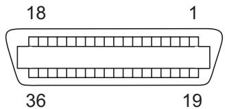
Transmission length: max. 2,0 m
Serial interface V.24/ RS232C
Your printer's serial interface supports the RS232C specification. The signals are received and transmitted by a 9 pin connector.
Basically 3 lines are already enough for exchanging information between computer and printer (one receive line, one send line, one line for common grounding).
| Type | RS232C interface |
| Synchronization | Asynchronous |
| Transmission rate | 600 Baud to 19.200 Baud |
| Signal status | OFF (log.1) -3 V to -15 V ON (log.0) +3 V to +15 V |
| Connection cable | up to 15 m length |
| Interface connections | ITT Cannon connector, series DB-9 S |
| Transmission protocol | XON/XOFF, Robust XON/XOFF |
| Capacity of data buffer | 128 KB max. |
Connector assignment
| Connector no. | Direction Printer-PC | Signal |
| 3 | → | TxD |
| 4 | → | DTR |
| 2 | ← | RxD |
| 6 | ← | DSR |
| 7 | → | RTS |
| 8 | ← | CTS |
| 5 | — | Signal Ground SG |
| Shield | — | Frame Ground FG |
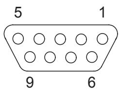
Transmission length: max. 15 m
Interface cable (serial interface)
The cables used must be shielded. The cable shield must be connected to the connector shield on both ends.
| PC/AT (9-pin) | Printer (9-pin) | ||
| RxD | 2 | 3 | TxD |
| TxD | 3 | 2 | RxD |
| CTS | 8 | 4 | DTR/RDY |
| SG | 5 | 5 | SG |
| DSR | 6 | ||
| DTR | 4 | ||
| PC/AT (25-pin) | Printer (9-pin) | ||
| FG | 1 | FG | |
| TxD | 2 | 2 | RxD |
| RxD | 3 | 3 | TxD |
| CTS | 8 | 4 | DTR/RDY |
| SG | 5 | 5 | SG |
| DSR | 6 | ||
| DTR | 4 | ||

It depends on the menu setting whether DTR or RDY is active at pin 4.
Input signals
| Signal | Function |
| CTS | Clear to Send |
| DSR | Data Set Ready |
| RxD | Receive Data |
Output signals
| Signal | Function |
| DTR | Data Terminal Ready |
| RTS | Request to Send |
| READY | Ready to receive data |
| TxD | Transmit Data |
| Ethernet interface | The Ethernet interface affords the printer to connect to local area networks. It's attributes are: |
| Hardware | LAN/Ethernet: RJ45, Ethernet 100BaseTX with 100 Mbps (IEEE802.3u), 10Base-T with 10 Mbps (IEEE802.3) |
| RAM: 8 MB | |
| Flash: 4 MB | |
| Speed: 100 Mbps / Full Duplex | |
| Supported operating systems | Windows XP, Windows Server 2003, Windows 2000, Windows NT |
| Linux | |
| Unix | |
| Sun Solaris | |
| Supported protocols | SNMP |
| SMTP | |
| TCP/IP | |
| FTP | |
| Ipr/Ipd | |
| Port 9100 | |
| Designation of IP address | DHCP |
| BOOTP | |
| Static (manually via the printer's control panel) | |
| Configuration | HTTP |
| TCP/IP | |
| Status | SNMP |
| TCP/IP | |
| SMTP | |
| PING | |
| Management | Web Panel |
| HP Web Jet Admin | |
| E-Mail notification with SMTP | |
| TGNet Admin | |
| Pre-string, Post-String | |
| Setup | Setup via the printer's control panel |
| Web Panel (HTTP/HTML) | |
| TGNet Admin |
Interface-Adapter IF Adapter-Set RS232 (DB9M)/MMP
The set consists of an adapter RS232 (D-Sub9)/MMJ and a MMJ cable.
| Adapter RS232(D-Sub9)/MMJ | |
| Serial connector | D-SUB9, male, 9 pins |
| Modular connector | DEC-MMJ, female, 6 pins |
| Internal wiring | MMJ D-SUB 9 |
| MMJ-Cable | |
| Length | 3 m, unshielded, leads crossed (1-6, 2-5, 3-4) |
| Connector | 2 x MMP, plug 6-pin |
| Internal wiring | |
| MMP | MMP |
| 1 | 6 |
| 2 | 5 |
| 3 | 4 |
| 4 | 3 |
| 5 | 2 |
| 6 | 1 |

Make sure that the ferrit bead always points in direction to the printer.
Protocols
Memory mode XON/XOFF
The received characters are stored in a FIFO buffer (first in/first out). The characters are processed in this buffer.
The buffer capacity can be adjusted from 0 to 128 Kb.
If the buffer is full, the interface signals NOT READY (signal acknowledgement: Level 1, -12 V) and XOFF (hex. 13, dec. 19). This results in stopping the data transmission. When the FIFO buffer is empty again, the interface signals READY (level 0, +12 V) and XON (hex. 11, dec. 17). Data transmission can be continued.
In addition, the READY signal is influenced by the status of the printer (On/Off Line). If the printer assumes an undefined state, the interface also signals NOT READY and XOFF.
Memory mode Robust XON/XOFF
Robust XON/XOFF is similar to XON/XOFF. However, the state of the printer (XON or XOFF) is also periodically transmitted via the TxD line in the case of Robust XON/XOFF.
Configuring the serial interface of the PC
| DOS mode | To use the serial interface of your PC, you must add the following mode commands to the AUTOEXEC.BAT file: mode com1:9600,n,8,1,p mode lpt1:= com1: With the first MODE command, you configure the serial interface Com1 of your PC to the printer's factory defaults. The second MODE command redirects the parallel standard output port LPT1 of your PC to Com1. Transmission rate: 9600 bauds Parity: none Data bits: 8 Stop bits: 1 These settings must be modified to use other values. |
| Windows 95/98/ME | Click on the Start button in the Windows taskbar. Move the mouse to Settings and click on Control Panel. Click on System, followed by Device Manager. Click on Ports, COM1 and Port Settings. Bits per second: 9600 bauds Data bits: 8 Parity: none Stop bits: 1 These settings must be modified to use other values. |
| Windows 2000/NT 4.0/XP | Click on the Start button in the Windows taskbar. Click on Printers and Faxes to open the printer folder. In the menu bar, click on File and Server Properties. Click on Ports, then select COM1 and click on Configure.... Bits per second: 9600 bauds Data bits: 8 Parity: none Stop bits: 1 These settings must be modified to use other values. |
Physical printer port in Ethernet with TCP/IP

Address information for the Ethernet port can only be made available by your network administrator, who has the necessary rights to install printers on the network and/or make any changes.
The assumed address space corresponds to the TCP/IP adress, class C, 192.168.1.xxx.
The subnet mask to be used is 255.255.255.0
The address of the router, or gateway, is 0.0.0.0, if not available.
Example of a printer connected to a computer in an Ethernet

Example of several devices in an Ethernet
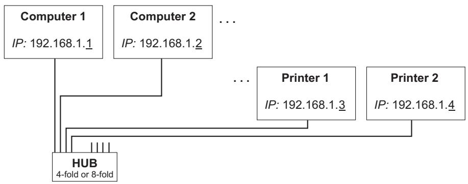

You will find more information on our internet page.

Options and accessories
Options
The following options can be ordered for your printer.
Tractor 2, front
The push tractor is suitable for fanfold paper. You can use paper formats with a width in the range from 76 to 406mm ; you can set any intermediate format.
Part no.: 061 052
Printer pedestal
A cabinet to be used as a printer stand and for storing fanfold paper stacks.
Part no.: 061910
Paper output tray
An optional accessory for the printer stand, useful for optimum output of prin-ted continuous forms.
Part no.: 060 833
Cable cover
Part no.: 061 909
Interface modules
The following interface modules are available.
| Name | Part no. |
| Serial interface RS422/V.11 | 048 956 |
| Serial line current interface TTY 20 mA | 048 957 |
| Ethernet interface module ENI/3 (multi-protocol TCP/IP, SPX/IPX) | 048 959 |
Accessories
Ribbon cassette
Ribbon cassettes are available in the following versions.
| Name | Part no. |
| Ribbon cassette, black | 060 097 |
Programming manuals
The available programming manuals are enclosed on this CD-ROM.
Index
A
Access to menu mode 45
Accessories 142, 143
Programming manuals 143
Ribbon cassette 143
ACK/NAK 140
Activation of automatic sheet feeder (AutoASF) 76
Activation of tractors (AutoTra) 75
Additional display messages 115
Advanced menu 100
Advanced settings 105
Automatic detection of the top paper margin 83
Automatic paper width detection 82
Deactivate single sheet feeder 106
Settings for paper with dark back 106
AED 83
AGA 77
APW 82
Auto-CR 65
Auto-LF 65
Automatic carriage return (Auto-CR) 65
Automatic detection of the top paper margin (AED) 83
Automatic gap adjustment (AGA) 77
Automatic line feed (Auto-LF) 65
Automatic paper motion sensor (PMS) 76
Automatic paper width detection (APW) 82
AutoTear 71
AutoTra 75
AutoView 71
Available barcodes 132
Available character sets and fonts 126
B
Banner 64
Banner page 64
Barcode 72, 132
Barmode 73
Baud 57
Beep at paper end (Sound) 80
Bidir 56
Bidirectional parallel interface (CX-bid) 80
Bidirectional printing (Bidir) 56
Botmrg 85
Buffer 60
C
Cable cover 142
Calling up the menu 45
Care 116
Carriage shafts 118
Changing
ribbon cassette 15
Changing printer settings 23
Changing the paper path 32
Character density
Setting 44
Character set
Available character sets and fonts 126
CharSet 87
Checking the printer voltage 8
Cleaning
Carriage shafts 118
Housing 117
Interior 117
Platen 118
Printer 117
Ribbon 118
Upper friction 118
Cleaning the printer 117
Connecting the printer 8
Control panel 26
Programming via 45
CPI 86, 92, 96
CX-bid 80
D
Data format (Format) 58
Data transmission rate (Baud) 57
DECMode 86
Display 27
Display messages 115
DTR 59
E
Emulations 131
Escape sequences 131
General 131
Error messages via the display 112
Escape sequences 131
ESCChar 54
Ethernetinterface62,137
ETH-INT 62
F
Fanfold paper
Loading 34
FFmode 74
Firmware
Loading 25
Troubleshooting 25
First printing position (FormAdj) 69
Font 53
Form feed mode (FFmode) 74
Form length (Forml) 68
Form settings 23
FormAdj 69
Format 58
Forml 68
Fuse
Replacing 116
G
Gateway 62
General print problems 108
Graphic options 24
H
Head 70
Head up 78
Hex-Dump 103
HvyForm 81
#
I/O 57
Increasing the printhead gap (Head up) 78
Ink cartridges 143
Input signals 136
Installation 6
Installing printer drivers 20
Installing the ink cartridge 10
Installing the ribbon cassette the first time 10
Interf. 60
Interface buffer (Buffer) 60
Interface cable (serial interface) 136
Interface modules 142
Interface specifications 123
Interface test (Hex-Dump) 103
Interfaces 133
Ethernet interface 137
Parallel interface 134
Serial interface 135
IP Addr 62
IP address administration 64
IP Get M 64
K
Key functions
when turning on the printer 31
L
Language 67
Selecting 48
LC display 27
Leftmrg 85
Leftzon 79
Line length 72
Line wrap (Wrap) 80
Loading menu configurations (Menu) 51
Loading optional firmware 25
Loading paper 34
LPI 54
M
Macro 51
Maintenance 116
Margin 84
MenLock 66
Menu 45
Advanced 100
Calling up 45
Enabling access to menu mode 45
Handling 47
Save settings 47
Selecting the LC display language 48
Terminating Setup mode 49
Menu configurations 46
Menu handling 47
Menu lock (MenLock) 66
Menu parameters 51
Activation of tractors 75
Automatic carriage return 65
Automatic gap adjustment 77
Automatic line feed 65
Automatic paper motion sensor 76
Banner page 64
Barcode 72
Beep at paper end 80
Bidirectional parallel interface 80
Bidirectional printing 56
BuffCtrl 59
Character set (DEC mode) 87
Data format 58
Data transmission rate 57
Ethernet interface 62
First printing position 69
Form feed mode 74
Form length 68
Horizontal spacing of characters (DEC mode) 86
Horizontal spacing of characters (EPSON mode) 96
Horizontal spacing of characters (IBM mode) 92
Increasing the printhead gap 78
Interface buffer 60
IP address administration 64
Language 67
Left-hand area 79
Line length 72
Line wrap 80
Loading menu configurations 51
Menu lock 66
Normal characters and barcode 73
Paper handling 77
Paper parameter 67
Paper width 78
Print head gap manually 70
Printing out menu configurations 51
Reset to default values 52
Right-hand area 79
Selecting emulation 55
Selectingfont53
Selecting interface 60
Selecting start signal for escape sequence 54
Serial interface 57
Setting and activating options 75
Setting for printing copy paper 81
setting Gateway address 62
setting IP address 62
Setting line spacing 54
Setting Subnet mask 63
Setting the bottom margin 85
Setting the DEC mode 86
Setting the left margin 85
Setting the page margins 84
Setting the top margin 84
Settings for interfaces 57
Signal processing 59
Tear position 71
User preference character set (DEC mode) 88
View position 71
Menu settings
Example 99
Menu structure 50
N
Normal characters and barcode (Barmode) 73
0
Offline mode 28
Online mode 28
Options 142
Cable cover 142
Interface modules 142
Printer pedestal 142
Tractor 2, front 142
Output signals 136
P
Pagewid 78
Pap.back 106
Paper 67
Fanfold paper 34
Moving to the tear position 39
Removing 40
Single sheets 36
Paper handling 32
Paper handling (Paphand) 77
Paper parameters (Paper) 67
Paper specifications
Standard printer 125
Paper transport 38
Paper type
Changing 32
Paper with dark back, setting 106
Paperways 5
Paphand 77
Papier
einlegen 34
PapOpt 75
Parallel interface 134
Parity error 113
Placing the printer 7
Platen
Cleaning 118
PMS 76
Print 51
Print quality
Problems with 111
Printer
At a glance 3
Connecting 8
Installation 6
Paperways 5
Placing 7
Specifications 119
Switching on 9
Unpacking 6
Printer drivers 20
Printer in single sheet mode 4
Printer in tractor mode 4
Printer pedestal 142
Printer self-test (Rolling ASCII) 101
Printer settings
Changing 23
Printhead gap adjustment, automatic 77
Printhead gap manually (Head) 70
Printing out menu configurations (Print) 51
Problems with the print quality 111
Programming manuals 143
Programming via the control panel 45
Protocol 55, 59
Protocol (Protocol) 59
Protocols 139
ACK/NAK 140
Robust XON/XOFF 139
XON/XOFF 139
Q
Quiet 52
Quiet mode printing (Quiet) 52
R
Removing paper 40
Replacing the fuse 116
Reset 52
Reset to default values (Reset) 52
Ribbon cassette 10
changing 15
Installing 10
Rightzo 79
Robust XON/XOFF 139
Rolling ASCII 101
s
Save menu settings 47
Selecting character density 44
Selecting emulation (Emulate) 55
Selectingfont (Font)53
Selecting interface (Interf.) 60
Selecting start signal for escape sequence
(ESCChar) 54
Selecting the LC display language 48
Serial 57
Serial interface
Connector assignment 135
Input signals 136
Interface cable 136
Output signals 136
Serial interface (Serial) 57
Serial interface V.24/RS232C 135
Setting and avitivating options (PapOpt) 75
Setting Gateway address 62
Setting IP address 62
Setting line spacing (LPI) 54
Setting Subnet mask 63
Setting the first printing line 42
Setting the print head gap 43
Setting the tear position 41
Settings 41
Advanced 105
Character density 44
First printing line 42
Font 44
Print head gap 43
Tear position 41
Settings for interfaces (I/O) 57
Settings for paper with dark back (Pap.back) 106
Setup mode 29
Terminating 49
Signal processing (DTR) 59
Single 106
Single sheets
Loading 36
Sound 80
Specifications 119
Interface specifications 123
Subnet 63
Switching on the printer 9
T
Tear position 39
Tear position (AutoTear) 71
Terminating Setup mode 49
Test functions 100
Interface test 103
Printer self-test 101
TOF
Setting the first printing line 42
Topmrg 84
Tractor 2 front 142
Troubleshooting 107
Additional display messages 115
Error messages via the display 112
General print problems 108
Problems with the print quality 111
U
Unpacking the printer 6
Upper friction
Cleaning 118
UserChr 88
V
View position (AutoView) 71
Voltage
Checking 8
W
Width 72
Wrap 80
X
XON/XOFF 139
TALLY REPRESENTATIVES
U.S.A.
TallyGenicom L.P.
4500 Daly Drive, Suite 100
Chantilly, VA 20151
U.S.A.
TallyGenicom Limited
Rutherford Road
Basingstoke, Hampshire
RG24 8PD
England, U.K.
Phone: +44 870 872 2888
Fax: +44 870 872 2889
http://www.tallygenicom.co.uk
SPAIN
TallyGenicom SRL
Joaquin Lorenzo 4, Local
28033 Madrid
Espana
Phone: +34 902 196 183
Fax: +34 913 739 943
http://www.tallygenicom.es
SINGAPORE
TallyGenicom Pte. Ltd
63 Hillview Avenue
08-22, Lam Soon Industrial Building
Singapore 669569
Phone: +65 6760 8833
Fax: +65 6760 1066
http://www.tallygenicom.com.sg
GERMANY
TallyGenicom
TallyGenicom Sdn. Bhd.
Wisma KT, Suite 3.02
No 14 Jalan 19/1
46300 Petaling Jaya
Selangor Darul Ehsan
Malaysia
Phone: +3 7625 1988
Fax: +3 7625 2688
http://www.tallygenicom.com.my
FRANCE
TallyGenicom S.A.
19 avenue de L'Ile Saint Martin
F-92237 Nanterre Cedex
France
Tél.: +33 1 41 30 11 00
Fax: +33 1 41 30 11 10
http://www.tallygenicom.fr
AUSTRIA
TallyGenicom Ges.m.b.H.
Eduard-Kittenberger-Gasse 95B
A-1232 Wien
Austria
Tel.: +43 1 863 40 0
Fax: +43 1 863 40 240
http://www.tallygenicom.at
Russian Federation and C.I.S.
TallyGenicom Representative
Park Place Moscow
Office D-206
Leninsky Prospekt 113/1
117198 Moscow
Russian Federation
Phone: +7 095 956 56 40
Fax: +7 095 956 55 41
http://www.tallygenicom.ru
- Printer at a glance 3
- Installation 6
- Inserting the ribbon cassette 10
- Printer drivers 20
- The control panel 26
- Paper handling 32
- Settings 41
- The Menu 45
- Advanced menu 100
- Troubleshooting 107
- Care and maintenance 116
- Specifications 119
- Available character sets and fonts 126
- Emulations 131
- Interfaces 133
- Options and accessories 142
- Index 144
- Introduction
- Printer features
- Symbols used
- About this manual
- Printer at a glance
- Printer in tractor mode
- Printer in single-sheet mode
- Paperway
- Installation
- Unpacking the printer
- Placing your printer
- Checking the printer voltage
- Connecting the printer
- Switching on the printer
- Inserting the ribbon cassette
- Installing the ribbon cassette the first time
- Changing the ribbon cassette
- 4
- Printer drivers
- Installing a printer driver in Windows 95/98/ME
- Installing a printer driver in Windows 2000/NT 4.0/XP
- Other operating systems
- Changing printer settings
- Form settings (Windows 2000/NT 4.0/XP)
- Graphic options
- Loading optional firmware
- The most current version of the firmware can be downloaded from our internet page.
- Troubleshooting
- The control panel
- The LC display
- Example:
- Online mode
- Offline mode
- Setup mode
- Messages in the LC display
- Key functions when turning on the printer
- Paper handling
- Changing the paper path
- Changing the paper type in the setup menu
- Loading paper
- Fanfold paper
- Single sheets
- Paper transport
- Moving the paper to the tear position
- Removing paper
- Settings
- Setting the tear position
- Setting the first printing line (TOF)
- Setting the print head gap
- Selecting character density and font (temporarily)
- The Menu
- Programming via the control panel
- Enabling access to menu mode
- Calling up the menu
- Menu configurations (Macros)
- Menu handling
- Save settings
- Selecting the LC display language
- Terminating Setup mode
- Menu structure
- Menu parameters
- Printing out macro configurations (Print)
- Loading menu configurations (Macro)
- Reset to default values (Reset)
- All manually altered settings in the current menu are lost when it is reset to the default settings.
- Quiet mode printing (Quiet)
- Selecting font (Font)
- Setting line spacing (LPI)
- Selecting start signal for escape sequence (ESC-Char)
- Selecting Protocol (emulation)
- Bidirectional printing (PrintDir)
- Settings for interfaces (I/O)
- Serial interface (Serial)
- Data transmission rate (Baud)
- Data format (Format)
- Buffer control (BuffCtrl)
- Signal Processing (DTR)
- Selecting interface (Interf.)
- Interface buffer (Buffer)
- Selecting interface timeout (Timeout)
- Ethernet interface (ETH-INT)
- Setting IP address (IP Addr)
- Setting Gateway address (Gateway)
- Setting Subnet mask (Subnet)
- IP address administration (IP Get M)
- Banner page (Banner)
- Automatic carriage return (Auto-CR)
- Automatic line feed (Auto-LF)
- Menu lock (MenLock)
- Language (Language)
- Paper parameters (Paper)
- Form length (Formlen)
- First printing position (FormAdj)
- Print head gap manually (Head)
- View and tear position (TearView)
- Line length (Width)
- Barcode (Barcode)
- Normal characters and barcode (Barmode)
- Setting Options: Secured/Unsecured Default Setting: Unsecured
- This function can be activated/deactivated by sequences.
- Form feed mode (FFmode)
- Setting and activating options (PapOpt)
- Activation of tractors (AutoTra)
- Automatic paper motion sensor (PMS)
- Automatic gap adjustment (AGA)
- Paper handling (Paphand)
- Increasing the print head gap (Head up)
- Paper width (Pagewid)
- Setting options: On/Off
- Printing is possible in the protected area.
- Left-hand area (Leftzon)
- Right-hand area (Rightzo)
- Bidirectional parallel interface (CX-bid)
- Line wrap (Wrap)
- Beep at paper end (Sound)
- Setting for printing copy paper (HvyForm)
- Automatic paper width detection (APW)
- Tractor: The measurement is made
- Automatic detection of the top paper margin (AED)
- Setting the page margins (Margin)
- Setting the top margin (Topmrg)
- Setting the bottom margin (Botmrg)
- Setting the left margin (Leftmgr)
- Setting the DEC Mode (DECMode)
- Horizontal spacing of characters (CPI)
- User preference character set (UserID)
- Printer ID (Prn.ID)
- Deleting sequence or buffer (CAN Fkt.)
- Setting options: Abort Sequ./Kill Buffer Default setting: Abort Sequ.
- Disconnection on end of transmission (Discnct)
- Initial Report (Report)
- Automatic answerback (Answerbck)
- Answerback on ENQ (Answer_ENQ)
- Setting the IBM mode (IBMMode)
- IBM character set (IBM-Cset)
- Code page (CodPage)
- IBM Double Height (DbHigh)
- Horizontal pitch on Compress (IBMComp)
- Slashed Zero (SI.Zero)
- Setting the EPSON Mode (EPSMode)
- EPSON character set (EPS-Cset)
- Advanced menu
- Test functions
- Printer self-test (Rolling ASCII)
- Exiting Rolling ASCII test mode
- Interface test (H-Dump)
- Printout in Hex-Dump
- Terminating Hex-Dump
- Advanced settings
- Deactivate single sheet feeder (Single)
- Settings for paper with dark back (Pap.back)
- Paper with a completely black back side cannot be used if the ink is carbon-based. However, the printer can handle aniline-based black paper (undefined colors).
- Troubleshooting
- General print problems
- Problems with the print quality
- Additional display messages
- Care and maintenance
- Cleaning the housing
- Cleaning the interior
- Cleaning the platen
- Ribbon
- Cleaning the upper friction
- Carriage shafts
- Specifications
- Available character sets and fonts
- Emulations
- General
- Escape sequences
- What are escape sequences?
- How are escape sequences used?
- Barcode
- List of available barcodes
- Interfaces
- Parallel interface
- Connector assignment
- Serial interface V.24/ RS232C
- Interface cable (serial interface)
- Interface-Adapter IF Adapter-Set RS232 (DB9M)/MMP
- Protocols
- Memory mode XON/XOFF
- Memory mode Robust XON/XOFF
- Configuring the serial interface of the PC
- Physical printer port in Ethernet with TCP/IP
- Options and accessories
- Options
- Tractor 2, front
- Printer pedestal
- Paper output tray
- Cable cover
- Interface modules
- Accessories
- Ribbon cassette
- Programming manuals
- Index
- A
- B
- C
- D
- E
- F
- G
- H
- #
- K
- L
- M
- N
- 0
- P
- Q
- R
- s
- T
- TOF
- U
- V
- W
- X
- TALLY REPRESENTATIVES
- U.S.A.
- SPAIN
- SINGAPORE
- GERMANY
- FRANCE
- AUSTRIA
- Russian Federation and C.I.S.
Brand : TALLYGENICOM
Model : LA800 PLUS
Category : Thermal printer