
Intelliprint 9035 - Printer TALLYGENICOM - Free user manual and instructions
Find the device manual for free Intelliprint 9035 TALLYGENICOM in PDF.


| Product Type | Laser Printer |
| Brand | TallyGenicom |
| Model | Intelliprint 9035 |
| Printing Technology | Laser xerography |
| Print Speed | 34 ppm (A4, long edge feed) |
| Resolution | Up to 1200 dpi (optional); 600 dpi standard |
| Paper Input Capacity | Standard: 150-sheet tray (A4/150) + 550-sheet tray (A4/550); up to 1800 sheets with optional trays |
| Paper Output Capacity | 500 sheets (face-down) or optional offset catch tray |
| Supported Media Sizes | A4, A5, B5, Letter, Legal 13/14, Executive, Statement, Envelopes (Com10, C5, DL, Monarch), Postcards, Custom sizes |
| Supported Media Types | Plain, thick paper (60–216 g/m²), transparencies, labels, envelopes, card stock |
| Duplex Printing | Optional (requires Duplex Module) |
| Connectivity | USB 2.0, Parallel, Ethernet 10/100 |
| Memory | 64 MB standard; upgradable via DRAM DIMM |
| Display Language | English, Spanish, Italian, German, French (selectable) |
| Power Consumption | Max 995 W (printing), 13 W (standby) |
| Dimensions (W×D×H) | 422 × 465 × 404 mm (without paper tray) |
| Weight | 21.0 kg (without toner, trays, paper); approx. 23 kg with standard supplies |
| Operating Environment | Temperature: 10–32°C; Humidity: 15–85% (non-condensing) |
| Safety Features | High voltage warning, fuser unit hot surface, auto power-off, ENERGY STAR compliant |
| Consumables & Life | Toner cartridge: ~17,000 pages (5% coverage); Fuser unit: ~200,000 pages; Transfer roll/feed roll: ~200,000 pages |
| Optional Accessories | Tray module (550 sheets), duplex module, offset catch tray, rear tray, hard disk, flash memory, DRAM DIMM |
| Software & Management | TGNet Admin (remote management), embedded web server (Printer Setup, Job Accounting, File Management) |
| Additional Features | Collating, saved jobs, job accounting, custom paper sizes, power-on files, PostScript 3 and PCL 6 support |
Frequently Asked Questions - Intelliprint 9035 TALLYGENICOM
User questions about Intelliprint 9035 TALLYGENICOM
0 question about this device. Answer the ones you know or ask your own.
Ask a new question about this device
Download the instructions for your Printer in PDF format for free! Find your manual Intelliprint 9035 - TALLYGENICOM and take your electronic device back in hand. On this page are published all the documents necessary for the use of your device. Intelliprint 9035 by TALLYGENICOM.
USER MANUAL Intelliprint 9035 TALLYGENICOM
TallyGenicom Intelliprint
9035
Laser Printer

natural_image
Line drawing of a printer with internal compartments and control panel (no text or symbols)Trademarks
The following are trademarks or registered trademarks of their respective owners. Other product names mentioned in this manual may also be trademarks or registered trademarks of their respective owners. Registered trademarks are registered in the United States Patent and Trademark Office; some trademarks may also be registered in other countries. TallyGenicom, is registered trademarks of TallyGenicom. PostScript is a trademark of Adobe Systems Incorporated for a page description language and may be registered in certain jurisdictions. Throughout this manual, "PostScript 3" (PS-3) is used to refer to a set of capabilities defined by Adobe Systems for its PostScript Level 3 page description language. Adobe, Adobe PhotoShop, Adobe PageMaker/Adobe Systems Incorporated. Apple, AppleTalk, EtherTalk, LaserWriter, LocalTalk, Macintosh, TrueType/Apple Computer, Inc. Banyan, VINES/Banyan. DEC, DECnet, LN03, VMS/Digital Equipment Corporation. Hewlett-Packard, HP, PCL, HP-GL, HP-UX, LaserJet/Hewlett-Packard Co. IBM PC, Token-Ring/International Business Machines Corporation. Intel/Intel Corporation. Microsoft, MS-DOS, Windows/Microsoft Corporation. Novell and NetWare/Novell, Inc. The ENERGY STAR logo/United States Environmental Protection Agency. The ENERGY STAR emblem does not represent EPA endorsement of any product or service. UNIX/UNIX Systems Laboratories. Ethernet/Xerox Corporation.
Copyright Notice
This manual is Copyrighted © 2004 by TallyGenicom. All Rights Reserved. This manual may not be copied in whole or in part, nor transferred to any other media or language, without the express written permission of TallyGenicom.
The specifications of your printer and the content of this publication are subject to change without prior notice. Every attempt has been made to verify the accuracy of the content herein.
Contents
Preface 0-1
Welcome 0-2
About this Manual 0-2
Scope 0-2
Overview 0-2
Printer Orientation 0-2
Conventions 0-2
Organization 0-3
Special Features of This Printer 0-4
Safety Notes 0-5
Chapter 1 Installing the Printer 1-1
About this Chapter 1-2
Installation Location 1-2
Installation Environment 1-2
Unsuitable locations 1-3
When using an ultrasonic humidifier 1-3
Safety Precautions 1-3
Handling the Printer 1-3
Printer Location Requirements 1-4
Printer Weight and Dimensions 1-4
Installation Space 1-4
Checking the Package Contents 1-6
Carrying the Printer 1-7
Installation Procedure 1-8
Removing the Tape 1-8
Installing the Optional Accessories 1-8
Installing the Toner Cartridge 1-8
Loading Paper 1-11
Loading paper larger than A4 size in the paper tray 1-13
Connecting the Power Cord 1-17
Turning the Printer On 1-18
Selecting a Display Language 1-18
Installing Printer Drivers and Locating User Documentation 1-20
Installing Printer Drivers and other Software for UNIX and
WindowsDrivers Folder 1-20
TGNET Admin Administration Program 1-21
Locating User Documentation 1-21
Printing a Configuration Summary 1-21
Printing PCL and PostScript Font Lists 1-24
Turning the Printer Off 1-24
Chapter 2 Daily Care 2-1
Main Components and Their Function 2-2
Front view 2-2
Control panel 2-3
Back view 2-3
Internal view 2-4
About Paper 2-4
Usable Paper 2-4
Paper for 2 sided printing 2-9
Unusable Paper 2-9
Storing Paper 2-10
Storing locations for paper 2-10
Caution for storing paper 2-10
Loading Paper 2-10
Loading Paper in Paper Tray 2-10
Loading Transparencies in the Paper Tray 2-13
Cleaning the Printer 2-17
Cleaning the exterior 2-17
Cleaning the interior 2-18
Cleaning the feed roll 2-18
When Not in Use for a Long Time 2-21
When Moving the Printer 2-22
Chapter 3 Troubleshooting 3-1
When Problems Occur 3-2
No Power 3-2
Cannot Print 3-2
Poor Print Quality 3-3
Paper Is Output Blank or All Black 3-3
Printout Is Faded, Stained, Missing, Wrinkled, or Blurred 3-4
Printing Is Not Clear 3-8
Paper Incorrectly Fed 3-9
Other Problems 3-10
Warning Messages and Error Messages 3-10
Warning Messages 3-11
Error Messages 3-12
Chapter 4 Clearing Paper Jams 4-1
Clearing Paper Jams 4-2
At the Paper Trays 4-3
At the Fuser Unit 4-5
At the Toner Cartridge 4-7
At the Duplex Module 4-9
At the paper exit 4-9
At the interior of the top cover 4-10
At the Offset Catch Tray 4-11
Chapter 5 About Consumables 5-1
Available Consumables 5-2
Toner Cartridge 5-2
Regular replacement parts 5-3
Toner Cartridge 5-4
Cautions on Handling the Toner Cartridge 5-4
Replacing the Toner Cartridge 5-4
Fuser Unit 5-7
Caution on Handling the Fuser Unit 5-7
Replacing the Fuser Unit 5-8
Transfer Roll Cartridge 5-11
Caution on Handling the Transfer Roll Cartridge 5-11
Replacing the Transfer Roll Cartridge 5-12
Feed Roll 5-15
Caution on Handling the Feed Roll 5-15
Replacing the Feed Roll 5-16
Chapter 6 Optional Accessories 6-1
Available Optional Accessories 6-2
Tray module (A4/550 sheets) 6-2
Installing/Uninstalling the Tray Module 6-2
Checking the contents of the tray module package 6-3
Installing the Tray Module 6-4
Uninstalling the Tray Module 6-9
Paper trays 6-13
Installing/Uninstalling the Duplex Module 6-13
Installing the Duplex Module 6-14
Uninstalling the Duplex Module 6-15
Offset catch tray 6-17
Installing/Uninstalling the Offset Catch Tray 6-18
Installing the Offset Catch Tray 6-18
Uninstalling the Offset Catch Tray 6-21
Rear tray 6-23
Installing/Uninstalling the Rear Tray 6-24
Installing the Rear Tray 6-24
Uninstalling the Rear Tray 6-25
Chapter 7 Understanding and Navigating the Control Panel Menus 7-1
About this Chapter 7-2
Control Panel Features 7-2
LCD Display 7-2
LED Indicators 7-3
Pushbuttons 7-3
Navigating the Control Panel Menus 7-4
Menu Structure 7-6
Status Menu 7-7
Job Library 7-7
Job Library Errors 7-9
Job Accounting 7-9
Paper Menu 7-10
Interface Menu 7-13
PS Menu 7-16
PCL Menu 7-17
System Menu 7-20
Quality Menu 7-21
Date/Time Menu 7-22
Functions Menu 7-23
FLASH Menu 7-24
DISK Menu 7-25
Chapter 8 Optional Extended Features 8-1
About this Chapter 8-2
Installing DRAM Memory DIMMS 8-2
Installing the Hard Disk Option in the Printer 8-5
Using the Hard Disk Option and User Flash DIMM Module 8-10
Operator Panel MENU Structure 8-10
Using the Disk Menu 8-11
Using the Flash Menu 8-11
Using the FLASH SIMM or Hard Disk Option as a PostScript Device 8-12
PostScript Operators 8-12
Device Parameter Sets 8-13
Warmstart.ps and Sys/Start Files 8-13
Using the Power-On Files Feature 8-14
Power-on Files Defined 8-14
Collating, Saved Jobs, and Job Accounting 8-15
Collating Feature 8-15
Saved Jobs Feature 8-18
Job Accounting Feature 8-24
Using the Custom Paper Size Feature 8-25
Operator Panel Access 8-25
Printer Driver Access 8-25
Custom Page size and Microsoft Word, Word 2000, and Word 2003 8-28
Resolution 8-28
Accessing the Printer Web Page 8-30
Printer Setup 8-36
Job Accounting 8-41
Appendix A Consumables A-1
Specifications A-2
Printable area A-3
Expected life of Consumables A-3
Toner Cartridge A-3
Fuser unit, transfer roll cartridge and feed roll A-4
Preface
In this Chapter ...
■ "Welcome" on page 2
■ "About this Manual" on page 2
■ "Organization" on page 3
■ "Special Features of This Printer" on page 4
Welcome
Thank you for selecting the Laser Printer. This User Guide contains important information about the operation and care of your printer. Please read this manual in its entirety and keep it at hand for later reference.
About this Manual
Scope
This User Guide contains all of the information necessary to operate and care for your printer and accessories. It is intended to be used with the pictorial unpacking instructions and the Installation Guide, both included in the printer packaging. If you have not already unpacked and installed the printer, please refer to these documents. This guide does not contain instructions for unpacking and installing the printer.
Overview
This manual contains nine chapters and one appendix:
Printer Orientation
Throughout this guide, the four sides of the printer are referred to as front, rear, right, and left. The front of the printer is the side near the control panel, and the rear of the printer is opposite the front. The left and right sides of the printer are defined as the sides to the left and right, respectively, of a person who is facing the front of the printer.
Conventions
This following conventions are used throughout this manual to emphasize certain procedures or information:
NOTE: A note is a tip or extra information that may be helpful in installing or using the printer.

CAUTION: A caution message provides information that may help you avoid equipment damage, process failure, or inconvenience. Read all caution messages carefully.

WARNING! A warning message indicates the possibility of personal injury if a specific procedure is not performed exactly as described in the guide. Pay close attention to these sections and read them fully to prevent possible injury.
Organization
The following is a summary of each chapter:
Safety Notes
This section explains the items of which to take note to ensure that you use this printer safely and correctly. Be sure to read this section to prevent serious injuries and accidents.
Preface
The Preface contains information about this guide and about the features and available configurations of the printer.
Chapter 1 Installing the Printer
This chapter explains the procedures to decide on the installation location, check the package contents, and set up the printer at the installation location.
Chapter 2 Daily Care
This chapter explains the essential operations for using the printer on a daily basis such as replenishing paper and cleaning.
Chapter 3 Troubleshooting
This chapter explains the problems that may arise when using the printer and the way of handling them. Do not consider the problems as a mechanical breakdown until you have read this chapter.
Chapter 4 Paper Jams
This chapter explains the ways to solve paper jams.
Chapter 5 Consumables
This chapter explains the essential consumables for this printer, cautions on using them, and the way of replacing them.
Chapter 6 Optional Accessories
This chapter explains the optional accessories and how to install and uninstall them.
Chapter 7 Navigating the Control Panel Menus
This chapter explains the control panel and its functions, and also demonstrates how to navigate throughout the various menus and submenus that allow you to view and change the printer settings.
Chapter 8 Optional Extended Features
This chapter describes the procedures for installation of DRAM Memory DIMMs and the Hard Disk Option. Also describes how to use the extended features associated with these options.
Appendix A
This Appendix includes the printer specifications and expected life of the consumables.
Special Features of This Printer
This printer has the following special features:
■ Quality printing at a high speed
With its 1,200 dpi laser-style resolution, it can print in high definition and high quality (optional feature). Attains high-speed printing of 34 sheets per minute when printing the same A4-sized document by long edge feed.
■ Flexible use of paper sources and delivery methods
A paper tray for various paper sizes, from A5 to Legal 14, can be used in the tray module. Special media such as envelopes and labels can also be used.
Optional tray module (A4/550 sheets) is available. By adding the optional tray module, you can load up to 1,800 sheets for the printer with 34 ppm.
You can add up to two optional tray modules.
Enables 2 sided printing by attaching the optional duplex module.
■ Network-readiness
The printer includes an Ethernet Network Interface Card.
■ Easy operation
The easy-to-read control panel display clearly shows the status of printer operation. Control panel pushbuttons allow you to access and view printer menus, submenus, and status messages.
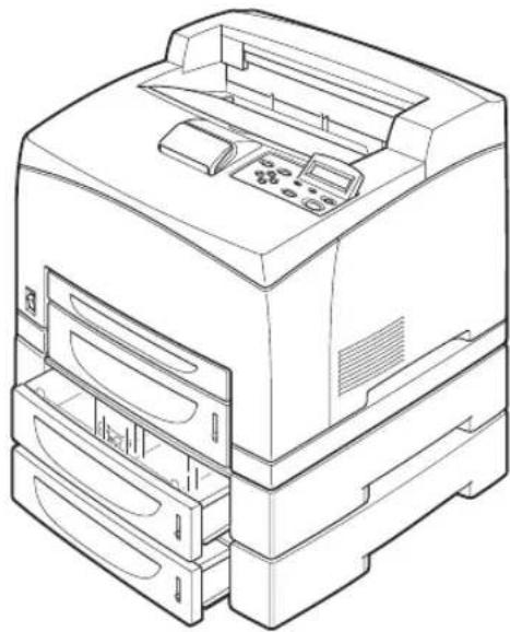
The following diagram shows the printer (34 ppm) with the 500 sheets exit as well as the two optional tray modules (A4/550 sheets) installed.
natural_image
Line drawing of a desktop computer with front panel and drive unit (no text or symbols)Safety Notes
For your own safety, please read this page carefully before using the machine.

■Do not place the machine in a hot, humid, dusty, or poorly ventilated environment. Prolonged exposure to these adverse conditions can cause fire or electric shock.

■Do not place the machine near heaters or volatile, flammable, or combustible materials such as curtains that may catch fire.
Chapter 1
Installing the Printer
In this Chapter . . .
■ "Installation Location" on page 1-2
■ "Safety Precautions" on page 1-3
■ "Printer Location Requirements" on page 1-4
■ "Installation Space" on page 1-4
■ "Checking the Package Contents" on page 1-6
■ "Carrying the Printer" on page 1-7
■ "Installation Procedure" on page 1-8
■ "Selecting a Display Language" on page 1-18
- “Installing Printer Drivers and Locating User Documentation” on page 1-20
■ "Printing a Configuration Summary" on page 1-21
■ "Printing PCL and PostScript Font Lists" on page 1-24
About this Chapter
This chapter reviews the contents of the printer packaging, explains the parts of the printer, and describes the space and environment requirements of the printer.
Installation Location
In order to make use of the printer safely and comfortably, choose an installation location with the following considerations.
Installation Environment
Suitable locations

CAUTION: Place the machine on a level and sturdy surface that can withstand a weight of 20.6 kg (for 34 ppm). If tilted, the machine may fall over and cause injuries.
■ Level and stable location (not tilted more than 5°)
■ Well-ventilated location
■ Temperature range: 10 to 32 °C; humidity range: 15 to 85% (no condensation) Humidity should be 70% or below at 32 °C, and temperature should be 28 °C or below at 85% humidity.
NOTE: Sudden temperature fluctuations can affect print quality. Rapid heating of a cold room or moving the printer from a location with low humidity/temperature to high humidity/temperature can cause condensation inside the printer, directly interfering with image transfer. When condensation occurs, leave the printer alone for at least 1 hour to acclimate to the environment before using it.
Using a power outlet exclusively for the printer
Use one power outlet exclusively for this printer. If the printer draws power from the same circuit as other large machines, such as copiers or air conditioners, the fluctuations in the current may cause malfunctions or a loss of data. Also, electrical noise produced by machines located nearby may interfere with the normal operation of the printer.

WARNING! Three power specifications are listed below. The specifications that apply to your printer depend on its configuration. Connect the power plug only to a properly rated power outlet. Otherwise, it can cause fire or electric shocks. If in doubt, contact our Printer Support Desk. Rated voltage: 100 V
Rated frequency: 50/60 Hz
Rated voltage: 110 V
Rated frequency: 60 Hz
Rated voltage: 220 – 240 V
Rated frequency: 50/60 Hz
Unsuitable locations
■ Locations with direct exposure to sunlight
■ Locations close to cooling/heating appliances
■ Locations with direct exposure to drafts
■ Locations susceptible to vibrations
■ Dusty and dirty locations
■ Locations close to open flame
■ Damp locations
■ Locations exposed to magnetic forces
■ Locations susceptible to sudden changes in temperature or humidity
When using an ultrasonic humidifier
If tap water or well water is used in the ultrasonic humidifier, the impurities in the water will be released to the atmosphere and adhere to the internal parts of the printer, and this may cause deterioration in the print quality. Use only water that does not contain any impurities in the ultrasonic humidifier.
Safety Precautions
This printer is available in either of the following power specifications: 110V and 220V. The specifications that apply to your printer depend on your machine configuration. To prevent fire or shock hazards, connect the power plug only to a properly rated power outlet.
Handling the Printer
Follow the guidelines below when lifting or moving the printer:
- The printer is very heavy, and should always be lifted by two people. The weight of the printer without paper tray, toner cartridge, and paper is about 51 lbs (23 kg). Never attempt to lift the printer alone.

natural_image
Line drawing of two hands opening a rectangular box with a striped pattern on the lid (no text or symbols)- To lift the printer, have two individuals facing each other from the front and the rear of the printer grasp the recessed areas on each side of the printer. Do not lift the printer by grasping any area other than these recessed areas.
- When lifting the printer, maintain proper lifting posture to prevent injuries.
Printer Location Requirements
Printer Weight and Dimensions
This printer weighs approximately 51 lbs (23 kg) and should always be lifted by two people. The dimensions of the printer are listed below.
■ Printer Height: 15.9 in (404 mm)
■ Printer Width (left to right): 16.6 in (422 mm)
■ Printer Depth (front to back): 18.3 in (465 mm)
Installation Space
Ensure that the printer has enough installation space as shown in the diagrams.

CAUTION: The machine has ventilation holes on the rear and side panels. Ensure that the machine is installed with a minimum clearance of 255 mm from the rear vent to the wall, 200 mm from the left vent to the wall, and 300 mm from the right vent to the wall. A poorly ventilated machine can cause excessive internal heat and fire. The accompanying diagram shows the minimum clearances required for normal operation, consumables replacement, and maintenance to ensure your machine operates at peak performance.
Top view

Front view

Side view

Checking the Package Contents
The standard configuration of the printer is as follows. Ensure that all the parts are available before installation.
NOTE: Retain the packaging material and box for future use if there is a possibility that the printer will be moved over long distances. See "Optional Accessories" on page 1-1 and the respective user guide of the optional accessories for details on the optional accessories.
- Printer

natural_image
Line drawing of a printer with control panel and paper tray (no text or symbols)■ Paper tray (A4/150 sheets) paper tray (A4/550 sheets)

natural_image
Technical line drawing of a mechanical housing or enclosure component (no text or symbols)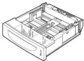
natural_image
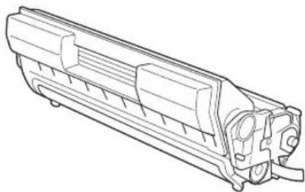
Technical line drawing of a mechanical device casing with internal compartments and mounting holes (no text or symbols)■ Toner Cartridge
natural_image
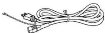
Technical line drawing of a mechanical component with internal channels and mounting holes (no text or symbols)■ Power cord
■ User guide
Carrying the Printer
When moving the printer to a place for installation, take note of the following points.
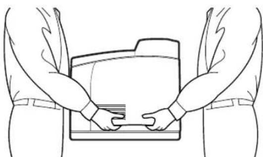
Hold the recessed areas on the left and right sides of the printer.

CAUTION: When lifting the printer, get a firm footing, bend your knees and use both your hands to avoid possible falls of the printer and injuries to your back.
NOTE: When lifting the printer, there should be 2 persons, one in front and one behind the printer, to firmly grip the recessed areas provided on both sides of the printer. Never try to lift the printer by gripping any other areas. Lifting the printer by gripping any other areas can cause the printer to fall and result in injuries.
natural_image
Line drawing of two hands holding a folder, viewed from the side (no text or symbols)NOTE: When lifting the printer, get a firm footing and bend your knees to avoid possible injuries to your back.
Carry the printer without tilting it.

CAUTION: When moving the machine, do not tilt it more than 10 degrees. If tilted excessively, the machine may fall over and cause injuries.
Do not tilt the printer more than 10 degrees to the front/back or right/left. This might lead to a malfunction due to incidents such as consumables inside the printer spilling out.
NOTE: Rear side of the printer is heavier than the front.
The rear side of this printer is heavier than the front. Take note of this difference in weight when moving the printer.
Installation Procedure
This section describes how to install the printer.
Removing the Tape
When the printer is first taken out of the packaging box, the covers of the printer are taped as shown in the diagram. Remove the tapes.

natural_image
Line drawing of a printer with control panel and buttons (no text or symbols)Installing the Optional Accessories
If you have purchased any optional accessories, install them before installing the Toner Cartridge and before loading paper. If there are no optional accessories to install, proceed to the next section, Installing the Toner Cartridge.
Tray module (A4/550 sheets)
See "Installing the Tray Module" on page 6-4 for details.
Duplex module
See "Installing the Duplex Module" on page 6-14 for details.
Offset catch tray
See "Installing the Offset Catch Tray" on page 6-18 for details.
Rear tray
See "Installing the Rear Tray" on page 6-24 for details.
Installing the Toner Cartridge
When installing the Toner Cartridge, take note of the following points:

WARNING! Never throw an Toner Cartridge into an open flame. It can cause an explosion and you can get burned.
■ Do not subject it to direct sunlight or strong light.
- When installing the TONER cartridge, select a location not subject to strong light and try to finish the installation within 5 minutes.
- Do not touch the surface of the photosensitive drum. Do not stand or place the Toner Cartridge upside down. The drum might get damaged.
■ A drum shutter protects the photosensitive drum from light. Do not open the drum shutter. - Although the toner is not harmful to the body, wash it off immediately if your hands or clothes are stained with it.
■ It is recommended to use up the Toner Cartridge within 1 year after opening it.
NOTE: See "Replacing the Toner Cartridge" on page 5-4 for details when replacing the Toner Cartridge.
- Open the top cover.

natural_image
Line drawing of a printer with an arrow indicating the paper's front cover (no text or symbols present)NOTE: Do not touch any parts inside the printer.
- Take the Toner Cartridge out of the box and shake it 7 to 8 times as shown in the diagram.

natural_image
Illustration of hands holding a cylindrical device with directional arrows indicating rotation (no text or symbols)- Place the Toner Cartridge on a flat surface and pull the scal out honnrizontally.

natural_image
Line drawing of hands operating a mechanical device with an arrow indicating motion (no text or symbols)NOTE: When pulling out the seal, pull it out horizontally. The tape might break if it is pulled out diagonally. After the seal has been pulled out, do not shake or bump the Toner Cartridge.
- Hold the Toner Cartridge by the grip and insert it into the slot inside the printer.

natural_image
Line drawing of a hand inserting a device into a printer (no text or symbols)NOTE: Do not touch any parts inside the printer. Ensure that the Toner Cartridge is firmly set.
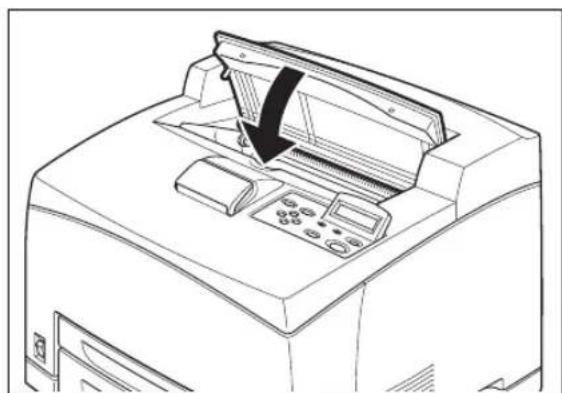
- Close the top cover securely.
natural_image
Line drawing of a printer with a paper airplane being inserted (no text or symbols)Loading Paper
Loading paper in the paper tray
See “About Paper” on page 2-4” for details on the type and size of paper that can be loaded in the paper tray.
- Place the paper tray on a flat surface.

natural_image
Technical line drawing of a mechanical device casing with internal compartments and mounting holes (no text or symbols)- Remove the lid of the tray.
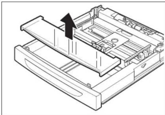
natural_image
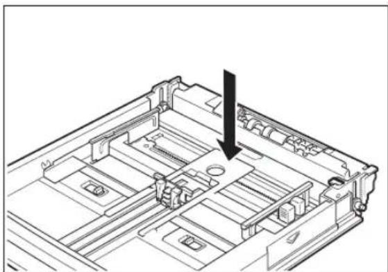
Technical line drawing of a mechanical assembly with an arrow indicating a process or operation (no text or symbols present)- If the base plate of the paper tray is raised, push it down.
natural_image
Technical line drawing of a mechanical assembly with a black arrow pointing to a component (no text or symbols present)- Squeeze the length guide and slide it to the desired paper size.

- Squeeze the right width guide and slide it to the desired paper size.

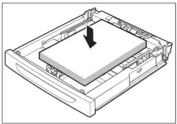
- Load the paper with the side to be printed facing up and with all 4 corners aligned. Make sure that the right width guide is correctly aligned with the paper size. Do not place paper over the right width guide.
natural_image
Technical line drawing of a mechanical device with a downward arrow indicating a component (no text or symbols present)NOTE: Do not load paper exceeding the maximum fill line or the maximum capacity allowed. Align the right width guide with the paper width correctly. If the right width guide is not in place, the paper will not be properly fed and may cause a paper jam.
- Close the lid of the paper tray.

natural_image
Technical line drawing of a mechanical assembly with a downward arrow indicating a component (no text or symbols present)- The lid of the tray must be firmly closed. If not, the paper might be misaligned.

natural_image
Line drawing of a printer with a paper feed insert and an arrow pointing to the paper's edge (no text or symbols present)Loading paper larger than A4 size in the paper tray
See “About Paper” on page 2-4 for details on the type and size of paper that can be loaded in the paper tray.
- Place the paper tray on a flat surface.

natural_image
Technical line drawing of a mechanical device casing with internal compartments and mounting holes (no text or symbols)- Remove the lid of the tray.

natural_image
Technical line drawing of a mechanical device with an arrow indicating a component (no text or symbols present)- Slide the right and left lock tabs in the paper tray outwards to unlock them.

natural_image
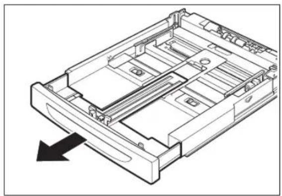
Technical diagram of a mechanical assembly with two circular insets showing internal components (no text or symbols)- Hold the grip of the paper tray and pull its extendable part to the front until it touches the desired paper size.
natural_image
Technical line drawing of a mechanical device casing with internal compartments and mounting holes (no text or symbols)NOTE: The right and left lock tabs in the paper tray move inwards and lock automatically.
- Squeeze the length guide and slide it to the desired paper size.

- Squeeze the right width guide and slide it to the desired paper size.
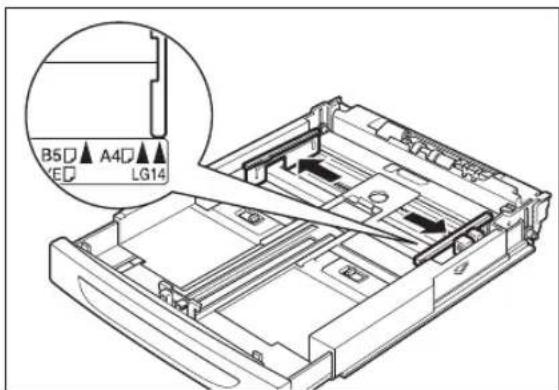
- Load the paper with the side to be printed facing up and with all 4 corners aligned. Do not place paper over the right width guide.

natural_image
Technical line drawing of a rectangular electronic device with a black arrow indicating a downward motion or force (no text or symbols present)NOTE: Do not load paper exceeding the maximum fill line or the maximum capacity allowed. Align the right width guide with the paper width correctly. If the right width guide is not in place, the paper will not be properly fed and may cause a paper jam.
- Close the lid of the paper tray.

natural_image
Technical line drawing of a mechanical device with a downward arrow indicating a component (no text or symbols present)NOTE: The lid of the tray must be firmly closed. If not, the paper might be misaligned.
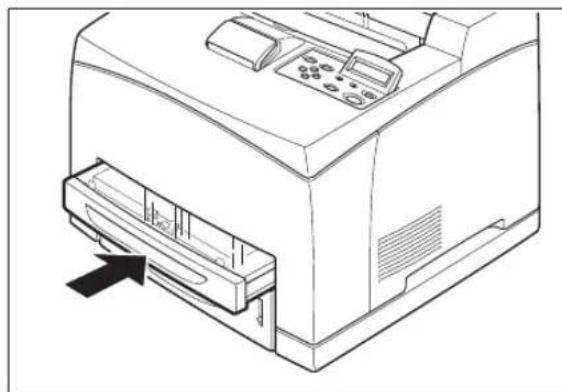
- Push the paper tray completely into the printer.
natural_image
Line drawing of a printer with control panel and paper feed (no text or symbols)Connecting the Power Cord

WARNING! Three power specifications are listed below. The specifications that apply to your printer depend on its configuration. Connect the power plug only to a properly rated power outlet. Otherwise, it can cause fire or electric shocks. If in doubt, contact our Printer Support Desk.
Rated voltage: 100 V
Rated frequency: 50/60 Hz
Rated voltage: 110 V
Rated frequency: 60 Hz
Rated voltage: 220 - 240 V
Rated frequency: 50/60 Hz
To prevent fire or electric shock, follow the instruction below based on your machine configuration. If in doubt, contact our Printer Support Desk.
If your machine is a 220 – 240 V model, there is no need to attach a separate earth line since the earth connection is incorporated in the power line. Plug it into a properly rated outlet.
If your machine is a 100 or 110 V model, use the green earth wire bundled with the power cord, located at the rear of the machine.
The earth wire must be connected to one of the following conductors:
– Earth terminal of the specified power outlet
- A piece of copper buried in the earth 650 mm or deeper
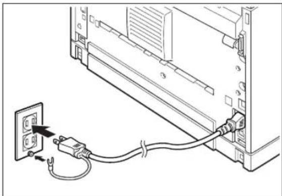
- Connect the power cord to the power cord connector at the back of the printer.

natural_image
Line drawing of a server rack with attached cable and connector (no text or symbols)- Make sure that the power switch has been firmly pushed to the position and then insert the other end of the power cord to the power outlet. If the power cord has an earth wire, connect it as well.
natural_image
Line drawing of a server rack with connected power cable and socket (no text or symbols)Turning the Printer On
Switch on the power before operating the printer. When you have finished using the printer for the day or you do not intend to use it for a long period of time, switch off the power.
- Press the power switch to the position the power on.

natural_image
Line drawing of a printer with a close-up inset showing a button labeled 'O' (no text or symbols on the device itself)On the printer's right side, press the side of the power switch marked to turn the printer on.
NOTE: The printer motors run for 2 or 3 minutes when you first turn the power on.
The top line of the LCD display reads:
Loading
followed by asterisks progressing across the bottom line:
************
Following an LED self test, asterisks progress across both lines of the display
************
************
and the Power On Self Test ends with the top line of the display reading:
Ready
NOTE: While turned on, the printer will go into the standby state if it remains idle for a period of time.
Selecting a Display Language
The default language for all LCD display messages and the Configuration Summary and Test Page is English. You can change the language to Espanol, Italiano, Deutsch or Francais.
NOTE: The language that you select will be reflected on all LCD display messages, and also the content of the Configuration Summary and Test Page.
To change the default language from English to one of the other four available selections:
- From the Ready status, press MENU, the control panel display will read:
Menu
Paper
- Press PREVIOUS or NEXT until the display reads:
Menu
System Menu
- Press SELECT, the display will read:
System Menu
Factory Defaults
- Press NEXT or PREVIOUS until the display reads:
System Menu
Display Language
- Press SELECT, the display will read:
System Menu
English
- Press NEXT or PREVIOUS until the desired default language appears on the bottom line of the display:
Press SELECT. You have now changed the default language.
Installing Printer Drivers and Locating User Documentation
Installing Printer Drivers and other Software for UNIX and WindowsDrivers Folder
For a printer to be connected using TCP/IP printing, ensure the printer has been configured for a valid IP address, subnet and gateway.
If this has been assigned by a DHCP server, ensure there is a reservation fo the printers mac address, seen on the network Configuration test page against the reserved IP address in the DHCP servers scope. See your company network manager if there is any doubt.
If the printer has not obtained an IP address subnet and gateway automatically refer to the Quick Start Guide.
Ensure the printer is powered on and has been connected to the network.
You must be logged on to the computer as an administrator or equivalent in order to install the printer drivers.
- Load the cd into the drive.
- After it loads select I ACCEPT to the opening screen as shown.
- Click MENU.
- Click PRINTER DRIVERS.
- Select your operating system and follow the instructions on the screen.
TGNET Admin Administration Program
The printer is supported by the TGNet Admin administration program, available from our web site. Network discovery, administration, remote monitoring and remote panel management options are available to the administrator.
The TGNet Admin program includes a virtual control panel function that allows the user to remotely manage the printer. The virtual control panel functions allow the administrator to remotely control many printers without having to go to each printer to modify the printer settings.
NOTE: For more information about obtaining TallyGenicom's TGNet Admin network administrator, please visit www.tallygenicom.com.
Locating User Documentation
To locate other documentation that will assist you in operating and maintaining your printer, go to the MANUALS folder on the Electronic Library CD-ROM. You can open and read these manuals (in Adobe PDF format) directly from the CD-ROM, save the manuals to the hard drive of your computer, or print the manuals.
Refer to the README.TXT file (UNIX and Windows) or the Read Me First file (MacOS) included in the MANUALS folder for more information about the documentation.
Printing a Configuration Summary
Your printer can print a configuration summary that lists the currently selected status of menu options, media selections in trays, options installed and other relevant information about your printer. To print a Configuration Summary, follow these steps:
- From the Ready status, press MENU, the control panel display will read:
Menu
Paper Menu
- Press PREVIOUS or NEXT until the display reads:
Menu
Functions
- Press SELECT, the display will read:
Functions
Reset Printer
- Press NEXT or PREVIOUS until the display reads:
Functions
Print Summary
- Press SELECT. A two page Configuration Summary will print. An example of a Configuration Summary appears on the following page.
NOTE: Depending upon the options installed and menu settings, your Configuration Summary may vary.
MENUS
Paper Menu
Copies = 1
Duplex = Off
Default Source = Tray 1
Output Tray = Face Down Tray
Media Size/Type
Tray 1
Media Type = Plain
Custom Size
Width = 209
Length = 295
Auto-Sense = On
Tray 2
Media Type = Plain
Custom Size
Width = 209
Length = 295
Auto-Sense = On
Tray 3
Media Type = Plain
Auto-Sense = On
Tray Linking = On
Blank Pages = Print
Output Linking = On
Auto Resize = Off
Separator Page = Off
Custom Size Unit = Millimitres
Interface Menu
Port
Parallel = On
Network Card 1 = On
USB = On
Parallel Setup
Mode = Bidirectional
Delay Out Close = Off
Binary PS = Off
Network 1 Setup
IP Address = 172.020.070.081
Subnet Mask = 255.255.000.000
Default Gateway = 010.005.001.001
LPD Banner = Off
DHCP = Off
Delay Out Close = Off
Host Name = Intelliprint9035017A03
mDNS = On
Network 1 Setup cont'd
Local Link = 169.254.122.003
mDNS Host Name = Intelliprint9035017A03
mDNS Svc Name = Intelliprint 9035 017A03
Multi-Session = On
AppleTalk = On
Current Zone = *
Preferred Zone = *
Binary PS = Off
Connection Speed = Auto-Sense
USB Setup
Delay Out Close = Off
Binary PS = Off
PS Menu
Print PS Errors = Off
PCL Menu
Orientation = Portrait
Font Source = Internal
Font Number = 50
Pitch = 10.00
Symbol Set = 10U:PC-8 CP437
Macro Filter = Off
Lines Per Page = 64
CR Mode = CR=CR
LF Mode = LF=LF
FF Mode = FF=FF
Print Area = Normal
Parameter Values
Paper Source
Tray 1 = 1
Tray 2 = 4
Tray 3 = 5
Auto-Select = 7
Paper Size
Executive = 1
Letter = 2
Legal = 3
Statement = 4
Folio = 5
A6 = 24
A5 = 25
A4 = 26
B5 = 45
Monarch Envelope = 80
Com10 Envelope = 81
DL Envelope = 90
C5 Envelope = 91
System Menu
Display Language = English
System Menu cont'd
Power Saver = 15
Wait Timeout = 20
Job Timeout = 0
Jam Recovery = On
Hex Print = Off
Toner Low = Stop
Page Compression = Off
Intellifilter = On
Quality Menu
Resolution = 600 dpi
Toner Saver = Off
Print Density = 5
Date/Time Menu
Month = February
Day = 2
Year = 2005
Hour = Noon
Minute = 33
Second = 38
Offset from GMT
Hours = 1
Minutes = 0
STATUS
Tray 1
Media Size = A4
Media Type = Plain
Level = OK
Tray 2
Media Size = A4
Media Type = Plain
Level = OK
Tray 3
Media Size = A4
Media Type = Plain
Level = OK
Face Down Tray = OK
Offset Tray = OK
Toner = OK
INFORMATION
Product Version:1.6
PostScript Version: 3010.106
Engine Version: 3.64-37
Network 1 Version: 10/100 Ethernet 1.2
Installed Memory : 64 Mbytes
Printer Name:Intelliprint 9035 017A03
Serial Number :
Asset Tag :
Image Counter : 939
Sheet Counter: 954
Toner Page Count: 824
HID=A1:2014,A2:80,S1:7,
M1:0000A0000000,P1:00005231
Date/Time:February2,200512:33:41AM
SF1:0000F38F*
OPTIONS
Duplex Installed
550 Sheet Feeder Installed
Offset Tray Installed
User FLASH Installed
Hard Drive Installed
Extended Font Set 1 Installed
Printing PCL and PostScript Font Lists
Your printer has the capability of printing lists of all installed PCL or PostScript fonts. To print a Font List, follow these steps:
- From the Ready status, press MENU, the control panel display will read:
Menu
Paper Menu
- Press PREVIOUS or NEXT until the display reads:
Menu
Functions
- Press SELECT, the display will read:
Functions
Reset Printer
- Press NEXT or PREVIOUS until the display reads:
Functions
Print Fonts
- Press SELECT, the display will read:
Print Fonts
PCL Fonts
NOTE: You may toggle between PCL Fonts and Postscript Fonts using the PREVIOUS or NEXT push-buttons.
- Press SELECT. A multi page resident Font List will print.
Turning the Printer Off
- Make sure that the printer is not in processing.

natural_image
Line drawing of a printer with a close-up inset showing a button or socket (no text or symbols)- Press the power switch to the <O> position to turn the power off.
Remember to turn off the printer at the end of day or when the printer will not be used for an extended period of time.
NOTE: When the printer is turned off, all print data still in memory will be erased.

Chapter 2
Daily Care
In this Chapter . . .
■ "Main Components and Their Function" on page 2-2
■ "About Paper" on page 2-4
■ "Storing Paper" on page 2-10
■ "Loading Paper" on page 2-10
■ "Cleaning the Printer" on page 2-17
■ "When Not in Use for a Long Time" on page 2-21
■ "When Moving the Printer" on page 2-22
Main Components and Their Function
Front view

| No. | Name Description | |
| 1 | Center output tray Print jobs are output with the printed side facing down. | |
| 2 | Control panel Consists of operation buttons, indicators, and the display. | |
| 3 | Ventilation hole Releases heat to prevent the interior of the printer from heating up. | |
| 4 | Paper meter Indicates the amount of paper remaining. | |
| 5 | Paper tray A4/550 sheets) Load paper here. | |
| 6 | Paper tray A4/150 sheets) Load paper here. | |
| 7 | Power switch Switches the power of the printer on and off. Pushing the switch to theside switches it on and pushing it to theside switches it off. | |
| 8 | Paper stopper Raise this when printing on paper larger than A4 size. |
Control panel

| No. | Name Description | |
| 1 | Control paneldisplay Displays error messages and printer menu dialogs. | |
Back view

| No. | Name Description | |
| 1 | Ventilation hole Releases heat to prevent the interior of the printer from heating up. | |
| 2 | Duplex module connector Connect the optional duplex module here. | |
| 3 | Power cord connector Connect the power cord here. | |
| 4 | USB port Connect the USB cable here. | |
| 5 | Ethernet 10/100 port Connect the Ethernet cable here. | |
| 5 | Parallel port Connect the parallel cable here. | |
Internal view

natural_image
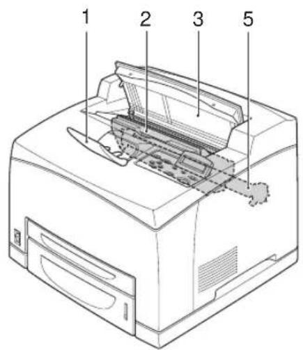
Line drawing of a printer internal structure with no text or symbols| No. | Name Description | |
| 1 | Paper stopper Raise this when printing on paper larger than A4 size. | |
| 2 | Toner Cartridge Contains the toner and the photosensitive drum. | |
| 3 | Top cover Open this when replacing the Toner Cartridge and removing jammed paper. | |
| 4 | Fuser unit Fixes the toner on the paper. Do not touch this when using the printer as it is hot. | |
| 5 | Transfer roll cartridge Transfers the toner image on the surface of the photosensitive drum to the paper. | |
About Paper
Using paper that is not suitable for this printer might lead to paper jams or poor print quality. To make full use of the printer features, we suggest using only paper that is recommended here.
Usable Paper
Printable paper
This printer can print on paper that is commonly sold. Select paper suitable for use by referring to the table below. However, we recommend the use of the standard paper for clearer printing.
| Paper feed G.S.M. | |
| Paper tray (A4/550 sheets) | 60 – 216 g/m ^2 |
NOTE: G.S.M. indicates the weight of a 1 m ^2 sheet of paper.
Standard paper
The standard paper that can be used for this printer is as follows.
| Paper type Paper size G.S.M. | |
| Fuji Xerox P paper A4 64 g/m | ^2 |
| 4024 20 lb Letter — | |
| 4200 20 lb Letter — | |
| RX 80 (3R 91720) A4 — |
Special media
The printer can also print on the following paper types. These types of paper are called special media.
| Paper size Paper type | ||
| Transparencies Letter (215.9 × 279.4 mm)A4 (210 × 297 mm) | XEROX P/N 3R2780XEROX P/N JE-001XEROX P/N 3R913343M P/N CG3300 | |
| Labels Letter (215.9 | × 279.4 mm)A4 (210 × 297 mm) | XEROX P/N 3R4469Avery Laser Labels P/N 5160XEROX P/N V860XEROX P/N 3R97408 |
| Envelopes Com#10 (104.8 × 241.3 mm)C5 (162 × 229 mm)DL (110 × 220 mm)Monarch (98.4 × 190.5 mm) | ||
| Postcards 100 | × 148 mm105 × 148.5 mm89.9 × 139.7 mm | Japanese official postcardsA6 postcardsUS postcards |
| Card stock 76.2 | × 127 mm –210 × 297 mm (A4) or215.9 × 279.4 mm (Letter) | 3" × 5" Oxford Index Card (40801)Classic Crest Super SmoothCover 3R3254 (Long Gain) |
Loadable paper and capacity
Paper that can be loaded in the paper trays (A4/150sheet) and (A4/550 sheets) is as follows:
■ Paper tray (A4/150 sheets), (A4/550 sheets)
The following paper types can be loaded in the paper trays:
| Paper type Maximum Capacity | ||
| Paper tray (A4/150 sheets) | Paper tray (A4/550 sheets) | |
| Standard paper 150 sheets 550 sheets | ||
| Other paper Up to a height of 17.5 mm | Up to a height of 59.4 mm | |
| Japanese official postcards 55 sheets 200 sheets or MAX 49.4 mm | ||
| Envelopes Columbian Com10 15 sheets | 80 sheets or MAX 49.4 mm | |
| Labels 100 sheets 350 sheets | ||
| Transparencies 100 sheets 100 sheets | ||
| Card stock 120 sheets 400 sheets | ||
Available paper sizes
The following paper sizes can be loaded in the paper tray:
Loadable: ⚙Not loadable: ✗
| Paper size | Paper tray (A4/150 sheets) | Paper tray (A4/550 sheets) |
| Letter portrait | ○ | ○ |
| Legal 14 portrait/landscape | ○ | ○ |
| Legal 13 portrait | ○ | ○ |
| A4 | ○ | ○ |
| B5 JIS portrait | ○ | ○ |
| B5 ISO portrait | ○ | ○ |
| A5 portrait | ○ | ○ |
| Executive portrait | ○ | ○ |
| 1/3 A4 portrait | ○ | ○ |
| Statement portrait | ○ | ○ |
| US postcard portrait | ○ | ○ |
| Index portrait | ○ | × |
| A6 postcard portrait | ○ | ○ |
| Japanese official postcard portrait | ○ | ○ |
| Envelope Monarch portrait | ○ | ○ |
| Envelope Com#10 portrait | ○ | ○ |
| Envelope C5 portrait | ○ | ○ |
| Envelope DL portrait | ○ | ○ |
| Free size Width: 98.4 – 215.9 mm | ○ | Length: 148.0 – 355.6 mm |
Paper for 2 sided printing
2 sided printing can be used by installing the optional duplex module.
The available paper types and sizes for 2 sided printing arc as follows:
| Paper type Paper size | G.S.M. | |
| Printable paper Letter | portraitLegal 13 portraitLegal 14 portraitA4 portraitB5 JIS portraitB5 ISO portraitA5 portraitExecutive portrait1/3 A4 portraitStatement portrait | 60 – 216 g/m ^2 |
| Postcards * Japanese | official postcardA6 postcardUS postcard | |
| Free size Tray 1 | Width: 89.9 – 215.9 mmLength: 139.7 – 355.6 mmTray 2, 3, and 4Width: 98.4 – 215.9 mmLength: 148.0 – 355.6 mm |
NOTE: *Print quality is not guaranteed.
Unusable Paper
Using the following types of paper might cause paper jams, malfunctions or damage to the printer. Do not use them.
■ FUJI XEROX full-color transparencies
■ Paper that is too thick or thin
■ Paper that has been printed on before (including color printing)
■ Wrinkled, folded, or torn paper
■ Wet paper
■ Curled paper
■ Paper with static electricity
■ Adhesive paper
■ Postcards with pictures
■ Paper with special coating on its surface
■ Treated colored paper
■ Paper using ink that will run at a temperature of 150^ C
■ Heat sensitive paper
■ Carbon paper
■ Paper with staples, paper clips, ribbons, or tape
■ Paper with rough surfaces such as pulp paper or fibrous paper
■ If acid paper is used, the characters might appear fuzzy. Replace it with alkaline paper.
■ Envelopes that are not flat or have metal fasteners
■ Labels which do not fully cover the adhesive backing
If background image suppression agent sticks to the feed roll when feeding postcards with pictures, the postcards may not feed. When this happens, clean the feed roll by referring to “Cleaning the Printer”.
Storing Paper
Even for suitable papers, poor storage conditions may lead to a change in the paper quality, paper jams, poor print quality and printer breakdown.
Storing locations for paper
■ Temperature: 10 – 30 °C
■ Relative humidity: 30 – 65%
Caution for storing paper
■ Store in a place with low humidity.
■ After opening a ream of paper, use the original cover sheets to wrap up the paper not used and store it in a cabinet or a location with low humidity.
■ Do not let the paper stand but store it in a flat location.
■ Ensure that the paper is stored properly without being bent or curled.
■ Store the paper in a location not exposed to direct sunlight.
Loading Paper
This section explains how to load paper when the paper in the paper tray runs out.
Loading Paper in Paper Tray
See “About Paper” on page 2-4 for details on the type and size of paper that can be loaded in the paper tray.
- Place the paper tray on a flat surface.

natural_image
Technical line drawing of a mechanical device casing with internal compartments and mounting holes (no text or symbols)- Remove the lid of the tray.

natural_image
Technical line drawing of a mechanical assembly with an arrow indicating a process or component (no text or symbols present)- If the base plate of the paper tray is raised, push it down.

natural_image
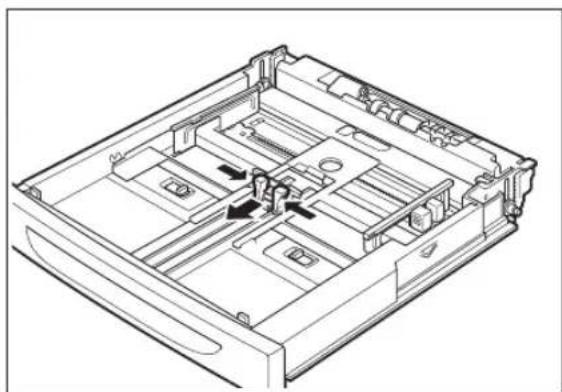
Technical line drawing of a mechanical assembly with a black arrow indicating a component (no text or symbols present)- Squeeze the length guide and slide it to the desired paper size.
natural_image
Technical line drawing of a mechanical device casing with internal compartments and mounting holes (no text or symbols)- Squeeze the right width guide and slide it to the desired paper size.

natural_image
Technical line drawing of a mechanical assembly with internal components and mounting holes (no text or symbols)- Load the paper with the side to be printed facing up and with all 4 corners aligned.

natural_image
Technical line drawing of a mechanical device with a downward arrow indicating a component (no text or symbols present)NOTE: Do not place paper over the right width guide. Do not load paper exceeding the maximum fill line or the maximum capacity allowed. Align the right width guide with the paper width correctly. If the right width guide is not in place, the paper will not be properly fed and cause paper jams. Load envelopes with the flaps closed.
- Close the lid of the paper tray.

natural_image
Technical line drawing of a mechanical assembly with a black arrow indicating a component (no text or symbols present)NOTE: The lid of the tray must be firmly closed. If not, the paper might become misaligned.
- Push the paper tray completely into the printer.

natural_image
Line drawing of a printer with a paper feed insert, showing no text or symbols on the device itself.Loading Transparencies in the Paper Tray
You can use transparencies for black and white printing only.
NOTE: Transparencies for full-color printing cannot be loaded. Using unsuitable transparencies may lead to a printer malfunction. If the output transparencies are allowed to stack up in the center output tray, paper jams may occur due to static electricity. Remove the transparencies from the tray as soon as they are output.
- Place the paper tray on a flat surface.

natural_image
Technical line drawing of a mechanical device casing with internal compartments and mounting holes (no text or symbols)- Remove the lid of the tray.

natural_image
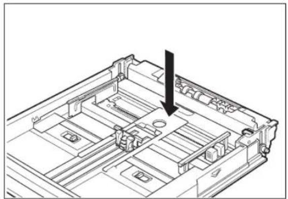
Technical line drawing of a mechanical device with an arrow indicating a component or assembly (no text or symbols present)- If the base plate of the paper tray is raised, push it down.
natural_image
Technical line drawing of a mechanical assembly with a black arrow indicating a component (no text or symbols present)- Squeeze the length guide and slide it to the desired transparency size.
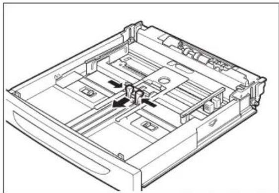
natural_image
Technical line drawing of a mechanical device casing with internal compartments and mounting holes (no text or symbols)- Squeeze the right width guide and slide it to the desired transparency size.
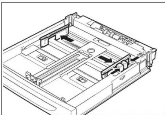
natural_image
Technical line drawing of a mechanical assembly with internal components and mounting holes (no text or symbols)- Fan the transparencies well in small amounts.

- Load the transparencies with the side to be printed facing up and with all 4 corners aligned. Do not place the transparencies over the right width guide.

natural_image
Technical line drawing of a mechanical device with a downward arrow indicating a component (no text or symbols present)NOTE: Transparencies for color printing may cause jams or fuser malfunctions. Do not use them. Do not load transparencies exceeding the maximum capacity allowed.
- Close the lid of the paper tray.
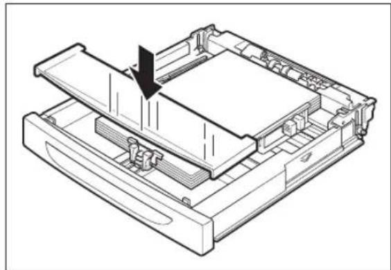
natural_image
Technical line drawing of a mechanical assembly with a downward arrow indicating a process (no text or symbols present)NOTE: The lid of the tray must be firmly closed. If not, the transparencies might become misaligned.
- Push the paper tray completely into the printer.

natural_image
Line drawing of a printer with a paper feed insert and an arrow pointing to the paper outlet (no text or symbols present)Cleaning the Printer
This section describes how to clean the printer in order to maintain the printer in good condition and print clean printouts all the time.

CAUTION: Be sure to switch off and unplug the machine before accessing the interior of the machine for cleaning, maintenance, or fault clearance. Access to a live machine's interior can cause electric shock.
Cleaning the exterior
Clean the exterior of the printer about once a month. Wipe the surface with a damp, well-wrung soft cloth. Then wipe with another dry soft cloth. For stubborn stains, moisten a soft cloth with a small amount of neutral detergent, and gently wipe the stain off.
NOTE: Do not spray the detergent directly on the printer. The liquid detergent may enter the printer through a gap and cause problems. Never use cleaning agents other than neutral detergent.

natural_image
Line drawing of a hand inserting a card into a printer (no text or symbols)Cleaning the interior
After clearing paper jams or replacing the Toner Cartridge, inspect the interior of the printer before closing the top cover.

CAUTION: Never touch areas labeled as "High Voltage." You can get an electric shock. Never touch a labeled area found on or near the heat roller. You can get burned. If a sheet of paper is wrapped around the heat roller, do not try to remove it by yourself to avoid injuries or burns. Switch off the machine immediately, and contact our Printer Support Desk.
■ Remove any remaining pieces of paper.
■ Remove any dust or stains with a dry clean cloth.

natural_image
Line drawing of a hand using a printer to press or download a machine (no text or symbols visible)Cleaning the feed roll
If background image suppression agent is stuck to the feed roll when feeding postcards with pictures, you may not be able to feed the postcards or paper. When feeding cannot be done, follow the procedure below to wipe the feed roll gently with a well-wrung soft cloth.
NOTE:
The following procedure explains how to clean the feed roll of the paper tray. Follow this procedure when cleaning the feed rolls inside the printer or of the tray module.
- Pull out the paper tray from the printer.
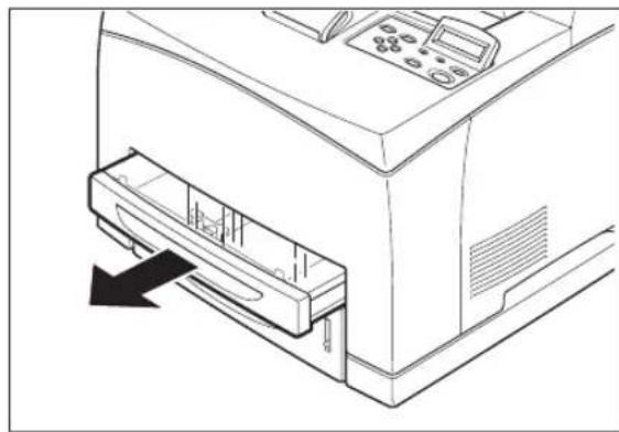
natural_image
Line drawing of a printer front panel with a paperclip inserted, showing no text or symbolsNOTE: You can clean the feed roll of the tray module without pulling out the paper tray.
- While pushing down the shaft of the feed roll (1), widen the tab of the feed roll to loosen it (2) and then slowly remove the feed roll from the shaft of the paper tray (3).

- Wipe the rubber parts with a damp, well-wrung soft cloth.

natural_image
Illustration of a hand turning a mechanical component with rotating parts (no text or symbols)- Hold the tab of the feed roll as shown in the diagram and slowly push it onto the shaft of the paper tray.

- By aligning the small tabs on the feed roll with the slots of the shaft, push the feed roll completely in so that the tab fits into the slot.

natural_image
Technical line drawing of a mechanical assembly with a directional arrow indicating motion (no text or symbols)- Push the paper tray completely into the printer.

natural_image
Line drawing of a printer with control panel and paper feed (no text or symbols)When Not in Use for a Long Time
Carry out the following procedure if you are not going to use the printer for a long period of time.
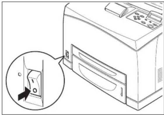
- Press the power switch to the <O> position to turn the power off.
natural_image
Line drawing of a computer with an inset showing a close-up of a device's internal structure (no text or symbols)- Remove all connection cords, such as the power cord and interface cables.

natural_image
Diagram showing cable connection between a computer tower and an electrical outlet (no text or symbols present)
WARNING! Never touch a power cord with wet hands. Danger of electric shock exists. When unplugging the machine, grasp the plug instead of the cord. Forcibly pulling on a cord can damage it and cause fire or electric shock.
- Remove the paper from the paper tray and store it in a location free of humidity and dust.
NOTE: See "About Paper" on page 2-4 for details on storing the paper.
When Moving the Printer
Carry out the following procedure when moving the printer.

CAUTION: When lifting the machine, get a firm footing and bend your knees to avoid possible injuries to your back.
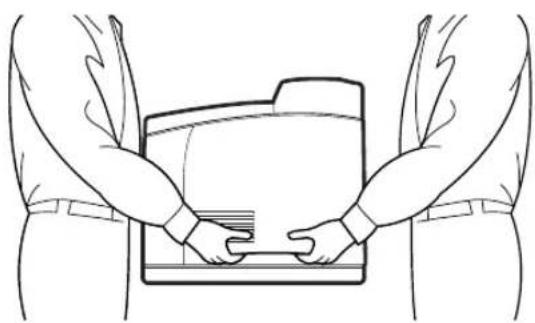
NOTE: The weight of this printer, without the optional accessories, paper tray, consumables and paper, is 21.0 kg. If the optional duplex module or tray module has been installed, uninstall it before moving the printer. Otherwise, they may fall to the ground and cause injuries. Refer to "Chapter 6 Optional Accessories" for details on uninstalling the optional accessories.
NOTE: When lifting the printer, there should be 2 persons, one in front and one behind the printer, to firmly grip the recessed areas provided on both sides of the printer. Never try to lift the printer by gripping any other areas. Lifting the printer by gripping any other areas can cause the printer to fall and result in injuries.
natural_image
Line drawing of two hands holding a folder, viewed from behind (no text or symbols)- Press the power switch to the <O> position to turn the power off.

natural_image
Line drawing of a printer with an inset showing a close-up of its internal component (no text or symbols present)- Remove all connection cords, such as the power cord and interface cables.

natural_image
Diagram showing connection between a computer tower and an electrical outlet, with no visible text or symbols
WARNING! Never touch a power cord with wet hands. Danger of electric shock exists. When unplugging the machine, grasp the plug instead of the cord. Forcibly pulling on a cord can damage it and cause fire or electric shock.
- Remove any paper in the center output tray (1) and return the paper stopper to its original position, if it's extended (2).

- Pull out the paper tray from the printer and remove any paper in the tray. Keep the paper wrapped and away from humidity and dirt.

natural_image
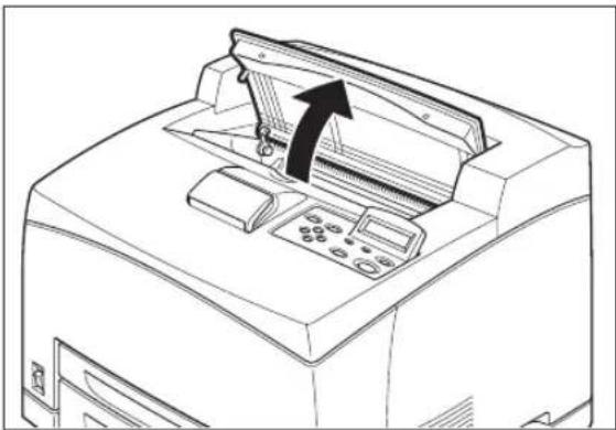
Line drawing of a mechanical device with a paper sheet being inserted into the top panel (no text or symbols)- Open the top cover.
natural_image
Line drawing of a printer's front panel with an arrow indicating the paper roll (no text or symbols present)NOTE: Do not touch any parts inside the printer.
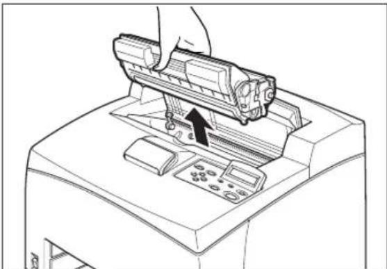
- Hold the Toner Cartridge by the grip to pull it out slowly.
natural_image
Line drawing of a hand using a handheld device to press or install a machine (no text or symbols visible)NOTE: It is necessary to remove the Toner Cartridge. If you move the printer with the Toner Cartridge installed, the toner may spill in the interior of the printer.
NOTE: Do not shake the Toner Cartridge after it has been removed from the printer. The toner will spill.
NOTE: After removing the Toner Cartridge, put it into its original aluminum bag or wrap it with a thick cloth to prevent it from being exposed to strong light.
- Close the top cover securely.

natural_image
Line drawing of a printer with a black arrow indicating the process (no text or symbols present)- Lift the printer and move it gently. If the printer is to be moved over a long distance, pack it inside a box.

natural_image
Line drawing of two hands holding a folder, viewed from behind (no text or symbols)Chapter 3
Troubleshooting
In this Chapter . . .
■ "When Problems Occur" on page 3-2
■ "No Power" on page 3-2
■ "Cannot Print" on page 3-2
■ "Poor Print Quality" on page 3-3
■ "Paper Incorrectly Fed" on page 3-9
■ "Other Problems" on page 3-10
■ "Warning Messages and Error Messages" on page 3-10
When Problems Occur
When problems occur while using the printer, search for the corresponding item from the following list of problems to carry out the appropriate action for the problem.
No Power
| Status Items to check | Action | |
| There is no power. Is the power switched off? Press the printer switch to theposition to turn the power on.See “Turning the Printer On“on page 1-18. | ||
| Is the power cord disconnected or not securely connected? | Switch off the power and connect the cord to the power outlet and printer again. Then, switch on the power.See “Connecting the Power Cord“on page 1-17. | |
| Power is interrupted frequently. | Printer may have malfunctioned. Switch off the power to the printer, remove the plug from the power outlet and contact our Printer Support Desk. | |
| Is the power cord disconnected or not securely connected? | Switch off the power and connect the cord to the power outlet and printer again. Then, switch on the power.See “Connecting the Power Cord“on page 1-17. | |
Cannot Print
| Status Items to check Action | ||
| Print instruction was sent but processing did not start. | Is the error indicator lit?Is the error indicator blinking?Is the print-ready indicator off? | Carry out the action according to the status of the indicator. |
| Is there any message displayed on the control panel? | Check the message, then carry out the action. | |
| Is there any message displayed in the computer? | Check the message, then carry out the action. |
Poor Print Quality
Paper Is Output Blank or All Black
| Status Items to check | Action | |
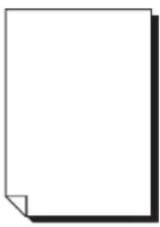 | Toner Cartridge pulled out? | Pull out the seal.See “Replacing the Toner Cartridge” on page 5-4. |
| Are two or more sheets of paper fed simultaneously? | Remove and fan the papers well.Then load them again. | |
| Is the Toner Cartridge defective or damaged? | Replace it with a new Toner Cartridge.See “Replacing the Toner Cartridge” on page 5-4. | |
| Is the Toner Cartridge correctly set? | Reset the Toner Cartridge correctly.See “Replacing the Toner Cartridge” on page 5-4. | |
| Printer may have malfunctioned. | Contact our Printer Support Desk. | |
| The entire paper is printed black. Is the Toner Cartridge defective or damaged? | Replace it with a new Toner Cartridge.See “Replacing the Toner Cartridge” on page 5-4. | |
 | Printer may have malfunctioned. | Contact our Printer Support Desk. |
Printout Is Faded, Stained, Missing, Wrinkled, or Blurred
| Status Items to check Action | ||
Printing is faded and blurred. Is the correct type of paper used? Load the correct type of paper. | Is the paper damp? Replace with paper from a new ream. | See “About Paper” on page 2-4. |
| Is the Toner Cartridge defective or damaged? | Replace with a new Toner Cartridge.See “Replacing the Toner Cartridge” on page 5-4. | |
| Is it time to replace the Toner Cartridge? | Replace with a new Toner Cartridge.See “Replacing the Toner Cartridge” on page 5-4. | |
| Are the levers at both ends of the fuser unit pushed up? | Push down the levers. | |
Black spots are printed. Is the correct type of paper used? Load the correct type of paper.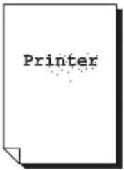 | type of paper used? Load the correct type of paper. | See “About Paper” on page 2-4. |
| Is the Toner Cartridge defective or damaged? | Replace it with a new Toner Cartridge.See “Replacing the Toner Cartridge” on page 5-4. | |
Black streaks are printed. Is the Toner  | Cartridge defective or damaged? | Replace it with a new Toner Cartridge.See “Replacing the Toner Cartridge” on page 5-4. |
| Dirt appears at equal intervals. The feed route of the paper may be stained. | Print a few pages to remove the stains. | |
 | Is the Toner Cartridge defective or damaged? | Replace it with a new Toner Cartridge.See “Replacing the Toner Cartridge” on page 5-4. |
Hair-like streaks are printed inside or outside the black halftone areas. | Are you using paper that has been left unwrapped for a long period of time (especially when the humidity is low)? | Replace with paper from a new ream.See “Loading Paper” on page 2-10. |
Shadows are printed around black filled areas. | Are you using paper that has been left unwrapped for a long period of time (especially when the humidity is low)? | Replace with paper from a new ream.See “Loading Paper” on page 2-10. |
White dots appear in black filled areas. | Is the correct type of paper used? Load the correct type of paper.See “About Paper” on page 2-4. | |
| Is the Toner Cartridge defective or damaged? | Replace it with a new Toner Cartridge.See “Replacing the Toner Cartridge” on page 5-4. | |
Printed image smudges when rubbed with your finger. | Is the paper damp? Replace with paper from a new ream.See “Loading Paper” on page 2-10. | |
| Is the correct type of paper used? Load the correct type of paper.See “About Paper” on page 2-4. | ||
Printed image appears partially blank. | Is the paper damp? Replace with paper from a new ream.See “Loading Paper” on page 2-10. | |
| Is the correct type of paper used? Load the correct type of paper.See “About Paper” on page 2-4. | ||
Image is printed at an angle.Image is printed at an unexpected location. | Are the paper tray guides set in the correct positions? | Set the length guide and width guide in the correct positions.See “Loading Paper” on page 2-10. |
Vertical blanks appear. Is the Toner 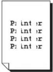 | Cartridge correctly set? Reset the Toner | Cartridge correctly.See “Replacing the Toner Cartridge” on page 5-4. |
| Is the Toner Cartridge defective or damaged? | Replace it with a new Toner Cartridge.See “Replacing the Toner Cartridge” on page 5-4. | |
| Paper is wrinkled. Is the correct type of paper used? Load the correct type of paper. See “About Paper” on page 2-4. | ||
 | Is the paper damp? Replace with paper from a new ream.See “Loading Paper” on page 2-10. | |
| Is the paper correctly set? | 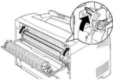 After printing the envelopes, you must return the levers to their original positions. After printing the envelopes, you must return the levers to their original positions. | |
| Envelopes are wrinkled. Envelopes may be wrinkled depending on the type used. | ||
| Text is blurred. Is the paper damp? Replace with paper from a new ream. See “Loading Paper” on page 2-10. | ||
| [ZZZD4] | Is the correct type of paper used? Load the correct type of paper.See “About Paper” on page 2-4. | |
Printing Is Not Clear
| Status Items to check | Action | |
| Transparencies are not printed clearly. | Are the correct type of transparencies used? | Load the correct type of transparencies.See “About Paper” on page 2-4. |
| Are the transparencies correctly loaded in the paper tray? | Load the transparencies correctly in the paper tray.See “Loading Transparencies in the Paper Tray” on page 2-13. | |
| Postcards are not printed clearly. Are | the correct type of postcards used? | Load the correct type of postcards.See “About Paper” on page 2-4. |
| Are the postcards correctly loaded in the paper tray? | Load the postcards correctly in the paper tray. | |
| Envelopes are not printed clearly. Are | the correct type of envelopes used? | Load the correct type of envelopes.“About Paper” on page 2-4. |
| Are the envelopes correctly loaded in the paper tray? | Load the envelopes correctly in the paper tray. |
Paper Incorrectly Fed
| Status Items to check Action | ||
| Paper cannot be fed.Paper jams occur.Multiple sheets of paper are fed.Paper is fed at an angle. | Is the paper correctly set? Load the paper correctly. For transparencies, postcards or envelopes, fan them well first to allow air to enter between each sheet before loading.See “Loading Paper” on page 2-10. | |
| Is the paper damp? Replace with paper from a new ream.See “Loading Paper” on page 2-10. | ||
| Is the correct type of paper used? Load the correct type of paper.See “About Paper” on page 2-4. | ||
| Is the paper tray pushed in? Push the paper tray completely into the printer. | ||
| Is the paper jammed? Remove the jammed paper.See “Clearing Paper Jams” on page 4-2. | ||
| Is the printer placed on a flat location? | Place the printer on a stable surface.See “Installation Environment”on page 1-2. | |
| Are the paper tray guides set in the correct positions? | Set the length guide and width guide in the correct positions.See “Loading Paper” on page 2-10. | |
| Did you print any picture postcards? | Clean the feed roll.See “Cleaning the Printer” on page 2-17. | |
Other Problems
| Status Items to check Action | ||
| Strange noise occurs. Is the printer placed on a flat location? | Shift the printer to a stable surface.See “Installation Environment”on page 1-2. | |
Warning Messages and Error Messages
The control panel display shows a warning message or error message when there is a problem with the printer. Some messages indicate routine status conditions such as an empty paper tray, while others indicate that a sheet of paper has jammed in a specific area of the printer. Some messages indicate more serious printer problems that may require the help of a service technician.
Warning messages use only the second line of the display and indicate conditions that do not prevent the printer from operating. For example, if Tray 1 is out of paper but the printer is currently drawing paper from Tray 2, a warning message will appear on the second line of the display indicating that Tray 1 is out of paper—but the printer will continue to operate, drawing paper from Tray 2.
Error messages use both lines of the display and indicate conditions that prevent the printer from operating. The first line of an error message contains the error code and type of error, while the second line of the display contains information about the action required to recover from the error.
When the control panel displays a warning or error message, refer to the following tables and complete the actions recommended for the specific message that is shown.
Warning Messages
The following table lists warning messages, possible causes, and the actions required to correct each cause.
| Warning Message Line 2 of display | Possible Cause Action | |
| Paper Out Tray 1 There is no paper in Tray 1. Add paper to the tray. | ||
| Paper Out Tray 2 There is no paper in Tray 2. Add paper to the tray. | ||
| Paper Out Tray 3 There is no paper in tray 3. Add paper to the tray. | ||
| Paper Out Tray 4 There is no paper in tray 4. Add paper to the tray. | ||
| Output Tray Full The output tray is full. Remove paper from the tray. | ||
| Offset Tray Full The offset output tray is full. Remove paper from the tray. | ||
| Toner Low The toner is low. Replace the toner cartridge soon. | ||
| Maint Req Maintenance is required. Install User Maintenance Kit. | ||
Error Messages
The table below lists error messages, the possible causes of each error, and the actions required to recover from each error.
| Error Message Line 1 | Error Message Line 2 | Possible Cause Action | |
| MISFEED JAME3 FUSER JAMEXIT JAMOFFSET TRAY JAME7 JAM DUPLEX | Remove Paper There is a paper jam inside the printer. | Remove the jammed paper from the indicated location. | |
| COVER OPEN Close Top Cover | The top cover is open. | Close the top or rear cover. | |
| COVER OPEN Close Rear Cover | The rear cover is open. | Close the rear cover. | |
| COVER OPEN Close OCT Cover | The offset tray cover is open. | Close the offset tray cover. | |
| TRAY 1 MISSING Insert Tray Tray 1 is not in the printer. | Insert the tray. | ||
| TRAY 2 MISSING Insert Tray Tray 2 is not in the optional feeder. | Insert the tray. | ||
| TRAY 3 MISSING Insert Tray Tray 3 is not in the optional feeder. | Insert the tray. | ||
| TRAY 4 MISSING Insert Tray Tray 4 is not in the optional feeder. | Insert the tray. | ||
| LOAD PAPER TRAY1 Paper Size/ Paper Type | Tray 1 is empty. Load paper into the tray. | ||
| LOAD PAPER TRAY2 Paper Size/ Paper Type | Tray 2 is empty. Load paper into the tray. | ||
| LOAD PAPER TRAY3 Paper Size/ Paper Type | Tray 3 is empty. Load paper into the tray. | ||
| LOAD PAPER TRAY4 Paper Size/ Paper Type | Tray 4 is empty. Load paper into the tray. | ||
| PAPER SIZE ERROR Paper Size/ Press Start | The paper size is not supported by the printer. | Check paper size specifications and load paper that meets specifications. | |
| OUTPUT TRAY FULL | Remove Paper | The output tray is full. | Remove paper from the tray. |
| OFFSET TRAY FULL Remove Paper The offset output tray is full. | Remove paper from the tray. | ||
| TONER MISSING Install/Reset The toner cartridge is missing or not installed correctly. | Install the toner cartridge or reisntall the toner correctly. | ||
| ID MISMATCH | Wrong toner cartridge is installed. | Remove toner cartridge and install the correct one. | |
| ROS FAILURE Call Service The ROS has failed. Turn the printer off. then turn it on. If the problem reoccurs, contact an authorized service provider. | |||
| FUSER FAILURE Call Service The fuser has failed. | |||
| OFFSET TRAY FAIL Call Service The offset tray was removed or has failed. | |||
| OPTION TRAY FAIL Call Service. One of the optional trays has failed. | |||
| DUPLEX FAILURE Call Service The duplexer was removed or has failed. | |||
| MAIN MOTOR FAIL Call Service The main motor has failed. | |||
| ENGINE NV FAIL Call Service The engine has failed. | |||
| FAN FAILURE Call Service The fan has failed. | |||
| MAINT REQ Press Start The printer needs maintenance. | Install User Maintenance Kit. | ||
Chapter 4
Clearing Paper Jams
In this Chapter . . .
■ "Clearing Paper Jams" on page 4-2
■ "At the Fuser Unit" on page 4-5
■ "At the Toner Cartridge" on page 4-7
■ "At the Duplex Module" on page 4-9
■ "At the Offset Catch Tray" on page 4-11
Clearing Paper Jams
When there is a paper jam, refer to the following diagram and the description of the action to be taken to remove the paper immediately.
NOTE: The diagram below shows the printer with the two optional tray modules, duplex module, and offset catch tray installed.
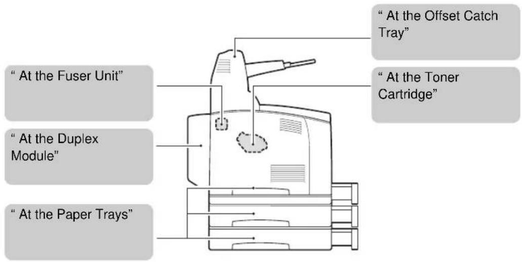

CAUTION: Never touch areas labeled as "High Voltage." You can get an electric shock. Never touch a labeled area found on or near the heat roller. You can get burnt. If a sheet of paper is wrapped around the heat roller, do not try to remove it by yourself to avoid injuries or burns. Switch off the machine immediately, and contact our Printer Support Desk.
NOTE: If the jammed paper is removed without opening the top cover, you still need to open and close the top cover. Doing this will remove the error message.
NOTE: Paper jams could be due to the printer installation environment and type of paper used. For details on selecting the appropriate location to install the printer, refer to "Installation Environment" on page 1-2. For details on selecting the correct type of paper, refer to "About Paper" on page 2-4.
At the Paper Trays
1. Pull the paper tray out of the printer.
The paper tray must be pulled out completely. If the paper tray is pulled out halfway and pushed in again, the paper may be damaged.

natural_image
Line drawing of a hand inserting a printer into a slot (no text or symbols)NOTE: If the paper is jammed inside the printer and behind the first level paper tray, pull out both the first and the second level paper trays.
NOTE: If the paper is jammed inside the printer and behind the second level paper tray, pull out only the second level paper tray.
2. Remove any wrinkled paper in the paper tray.

natural_image
Technical line drawing of a mechanical device with a central component and an upward arrow indicating motion (no text or symbols)- Remove any paper jammed inside the printer.

natural_image
Line drawing of a printer with a hand inserting a slot into the base (no text or symbols)NOTE: If the printer is installed with the two optional tray modules, examine the interior of all the tray modules.
NOTE: If the printer is installed with the two optional tray modules and the A5-sized paper (length 148.5 mm) of the short edge feed is jammed inside the feeder, use both hands to grip the both ends of the paper to pull it out to the front.
- Push the paper tray completely into the printer.
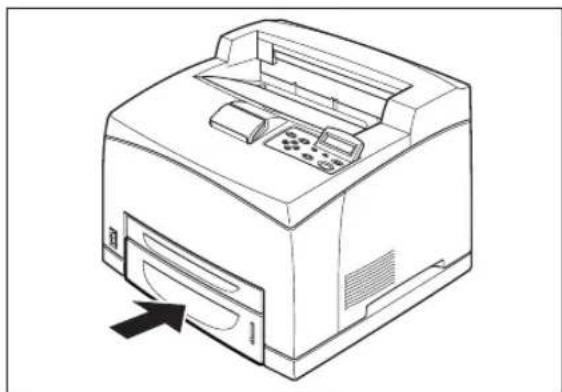
natural_image
Line drawing of a printer with a paper feed and paper clip, showing no text or symbols- Open and close the top cover.

natural_image
Line drawing of a printer with an open lid and internal circuit board (no text or symbols)At the Fuser Unit
- Remove any paper from the center output tray.

natural_image
Line drawing of a printer with a paper lid and an arrow pointing to the cover (no text or symbols)NOTE: If the duplex unit is installed, open the cover of the duplex unit first. See "At the Duplex Module" on page 4-9.
- Lift the second lever from the top left corner of the back of the printer.

natural_image
Technical line drawing of a printer or printer with an inset showing a close-up of its internal structure (no text or symbols present)- Open the rear cover.
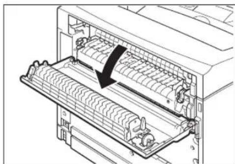
natural_image
Diagram of a computer rack with internal components and a black arrow indicating a specific component (no text or symbols present)NOTE: Do not touch any parts inside the printer.
- Open the cover of the fuser unit and remove any jammed paper. If paper is torn, check for any remaining torn pieces of paper.
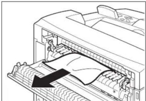
natural_image
Line drawing of a printer with a paper roll being inserted, showing internal components and a black arrow indicating the process (no text or symbols present)NOTE: The fuser unit is hot. Be careful not to touch it as you can get burned. Make sure that the levers at both ends of the fuser unit are returned to the positions they were in before clearing the jam.. If you let go of the cover of the fuser unit, it will return to its original position.
- Close the rear cover.

natural_image
Technical line drawings of a printer with internal components, showing top and side views (no text or symbols)NOTE: Make sure that the levers at the rear of the printer, as shown in the diagram, are returned to the positions they were in before clearing the jam.
- Open and close the top cover.

natural_image
Line drawing of a printer with an open lid and control panel, showing a double arrow indicating compression or disassembly (no text or symbols present)At the Toner Cartridge
- Remove any paper in the center output tray.
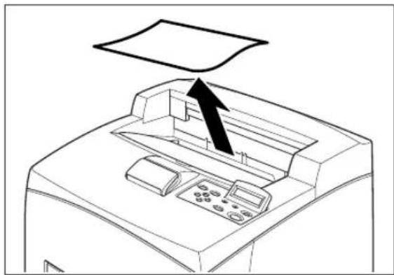
natural_image
Line drawing of a printer with a paper feeding into the top page (no text or symbols)- Open the top cover.
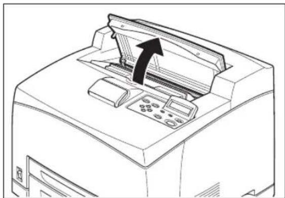
natural_image
Line drawing of a printer with an arrow indicating the paper's front cover (no text or symbols present)NOTE: Do not touch any parts inside the printer.
- Hold the Toner Cartridge by the grip and pull it out slowly. Then place it on a flat surface.

natural_image
Line drawing of a hand inserting a device into a machine (no text or symbols)NOTE: To prevent the toner from dirtying the floor, lay a piece of paper on the floor before putting the Toner Cartridge down.
- Examine the interior from which the Toner Cartridge has been taken out and remove any jammed paper. By rotating the rollers as shown in the diagram, the paper will be loosened and can be removed easily. If paper is torn, check for any remaining torn pieces of paper.

natural_image
Technical line drawing of a mechanical assembly with rollers and components (no text or symbols)- Hold the Toner Cartridge by the grip and insert it into the slot inside the printer.

natural_image
Line drawing of a hand operating a printer with a control panel and paper airplane (no text or symbols)NOTE: Do not touch any parts inside the printer. Ensure that the Toner Cartridge is firmly set.
- Close the top cover securely.

natural_image
Line drawing of a printer with a paperclip inserted into the cover (no text or symbols)At the Duplex Module
At the paper exit
- Examine the paper exit and remove any jammed paper. If paper is torn, check for any remaining torn pieces of paper.

natural_image
Line drawing of a printer with control panel and paper tray (no text or symbols)NOTE: If the paper is difficult to remove, carry out the operation in the following section, See "At the interior of the top cover" on page 4-10.
- Open and close the top cover.
At the interior of the top cover
- Lift the lever at the top left hand side of the duplex module to unlock it and open the top cover of the duplex module.

- Examine the interior of the top cover and remove any jammed paper. If paper is torn, check for any remaining torn pieces of paper.

natural_image
Diagram of a printer's internal structure showing blade and handle mechanism (no text or symbols)- Close the top cover of the duplex module.

natural_image
Technical line drawing of a mechanical device with a black arrow indicating a component or connection (no text or symbols present)At the Offset Catch Tray
- Open the offset catch tray cover by pulling the tab at the top left of the cover.

natural_image
Diagram of a printer internal structure showing internal components and a black arrow indicating a downward motion (no text or symbols present)- Remove any jammed paper.

natural_image
Technical line drawing of a mechanical device interior showing internal components and a black arrow indicating a specific area (no text or symbols present)- Close the offset catch tray cover.
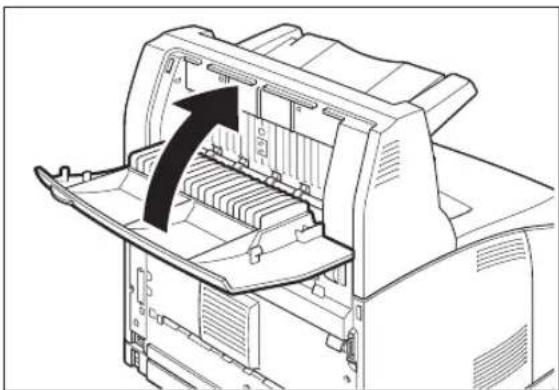
natural_image
Technical line drawing of a printer internal structure with an arrow indicating a component (no text or symbols present)- Lift up the second lever from the top left corner of the back of the printer to open the rear cover.
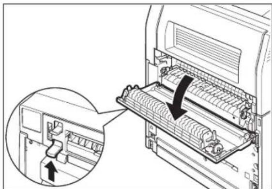
natural_image
Diagram of a computer rack with a close-up inset showing internal components (no text or symbols)- Remove any jammed paper. If paper is torn, check for any remaining torn pieces of paper.

natural_image
Technical line drawing of a printer with paper feed being inserted (no text or symbols)NOTE: The fuser unit is hot. Be careful not to touch it as you can get burned. Make sure that the levers at both ends of the fuser unit are returned to the positions they were in before clearing the jam.
NOTE: If you let go of the cover of the fuser unit, it will return to its original position.
- Close the rear cover.

natural_image
Line drawing of a printer's internal structure showing paper feed and paper tray (no text or symbols)NOTE: Make sure that the levers at the rear of the printer, as shown in the diagram, are returned to the positions they were in before clearing the jam.
Chapter 5
About Consumables
In this Chapter . . .
■ "Available Consumables" on page 5-2
■ "Toner Cartridge" on page 5-4
■ "Fuser Unit" on page 5-7
■ "Transfer Roll Cartridge" on page 5-11
■ "Fccd Roll" on page 5-15
Available Consumables
The following consumables are available for this printer. To order these, contact our Printer Support Desk.
Toner Cartridge
The Toner Cartridge includes the toner and the photosensitive drum. If the toner in the Toner Cartridge is insufficient, the printout will become light and blurred. If it is time for replacement, replace with a new Toner Cartridge.
The following Toner Cartridge is available:
■ 17 Kpv: can print approximately 17,000 pages

natural_image
Technical line drawing of a mechanical component with internal channels and mounting brackets (no text or symbols)NOTE: The possible number of pages that can be printed is based on Letter size paper with a print ratio of 5% and the default density setting using one Toner Cartridge. The number of pages that can be actually printed varies according to the conditions of use.
IMPORTANT: Use of Toner Cartridges not recommended by our company may impair print quality or printer performance. Use only Toner Cartridges recommended by our company on this printer.
NOTE: See "Toner Cartridge" on page 5-4 for details on how to replace the Toner Cartridge.
Regular replacement parts
Regular replacement parts packaged together include the fuser unit, the transfer roll cartridge, and the feed roll. About 200,000 pages for a fuser unit, a transfer roll cartridge and a feed roll can be printed. When these parts have reached this limit, replace them with new ones.
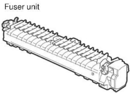

Feed roll

NOTE: The possible number of pages that can be printed is based on Letter size paper with a print ratio of 5% and the default density setting. The number of pages that can be actually printed varies according to the conditions of use.
Refer to: "Fuser Unit" on page 5-7 for details on how to replace the fuser unit. "Transfer Roll Cartridge" on page 5-11 for details on how to replace the transfer roll cartridge. "Feed Roll" on page 5-15 for details on how to replace the feed roll.
Toner Cartridge
This section explains about the Toner Cartridge.
Cautions on Handling the Toner Cartridge
When handling the Toner Cartridge, take note of the following points:

WARNING! Never throw an Toner Cartridge into an open flame. It can cause an explosion and you can get burned.
■ Do not subject it to direct sunlight or strong light.
- When installing the Toner Cartridge, select a location not subject to strong light and try to finish the installation within 5 minutes.
- Do not touch the surface of the photosensitive drum. Do not let the Toner Cartridge stand or place it upside down. The drum might get damaged.
■ A drum shutter protects the photosensitive drum from light. Do not open the drum shutter.
Although the toner is not harmful to the body, wash it off immediately if your hands or clothes are stained with it.
■ It is recommended to use up the Toner Cartridge within 1 year after opening it.
Replacing the Toner Cartridge
- Switch off the power of the printer.

natural_image
Line drawing of a printer with a close-up inset showing a switch mechanism (no text or symbols)- Remove any paper in the center output tray.
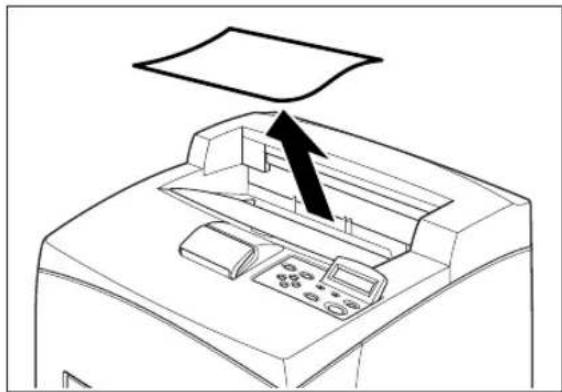
natural_image
Line drawing of a printer with a paper sheet above it, showing internal components and a black arrow indicating the paper's direction (no text or symbols present)- Open the top cover.

natural_image
Line drawing of a printer with an arrow indicating the paper's front cover (no text or symbols present)NOTE: Do not touch any parts inside the printer.
- Hold the Toner Cartridge by the grip and pull it out slowly.

natural_image
Line drawing of a hand inserting a device into a printer (no text or symbols)NOTE: To prevent the toner from dirtying the floor, lay a piece of paper on the floor first before putting the Toner Cartridge down.
- Take the new Toner Cartridge out of the box and shake it 7 to 8 times as shown in the diagram.

natural_image
Illustration of hands holding a cylindrical device with rotating arrows indicating rotation (no text or symbols)IMPORTANT: If the toner is not evenly spread out, the print quality may drop. Also, if you did not shake the cartridge well, there may be operating noise or the interior of the Toner Cartridge may be damaged during operation. Do not touch the surface of the photosensitive drum.
- Place the Toner Cartridge on a flat surface and pull out the seal horizontally.

natural_image
Line drawing of hands operating a mechanical device with a black arrow indicating rotation (no text or symbols)IMPORTANT: When pulling out the seal, pull it out horizontally. The tape might break if it is pulled out diagonally. After the seal has been pulled out, do not shake or dump the Toner Cartridge.
- Hold the Toner Cartridge by the grip and insert it into the slot inside the printer.

natural_image
Line drawing of a printer's front panel with a hand operating the top panel (no text or symbols)IMPORTANT: Do not touch any parts inside the printer. Ensure that the Toner Cartridge is firmly set.
- Close the top cover securely.
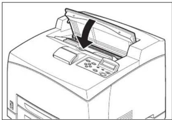
natural_image
Line drawing of a printer with control panel and paper tray (no text or symbols)Fuser Unit
This section explains about the fuser unit.
Caution on Handling the Fuser Unit
The fuser unit is included as one of the regular replacement parts. Before replacing the fuser unit, open the box of the regular replacement parts and get the new fuser unit ready.
When handling the fuser unit, take note of the following points:

CAUTION: Never touch a labeled area found on or near the heat roller. You can get burnt. If a sheet of paper is wrapped around the heat roller, do not try to remove it by yourself to avoid injuries or burns. Switch off the machine immediately, and contact our Printer Support Desk. Be sure to switch off and unplug the machine before accessing the interior of the machine for cleaning, maintenance, or fault clearance. Access to a live machine's interior can cause electric shock.
Do not replace the fuser unit immediately after using the printer. You may get burned.

natural_image
Technical line drawing of a mechanical component with grooved ends and internal channels (no text or symbols)Replacing the Fuser Unit
- Switch off the power of the printer and leave it for 30 minutes until the fuser unit cools down.

natural_image
Line drawing of a printer with an inset showing a close-up of the front panel (no text or symbols present)- Remove any paper in the center output tray.

natural_image
Line drawing of a printer with a paper feeding into the top panel (no text or symbols)- Lift the second lever from the top left corner of the back of the printer.
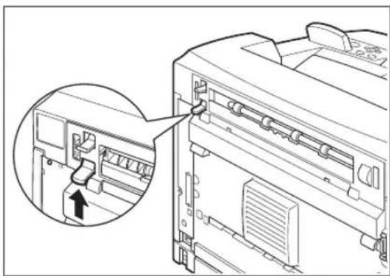
natural_image
Technical line drawing of a printer internal structure with an inset showing a close-up of the component (no text or symbols present)- Open the rear cover.

natural_image
Diagram of a mechanical device with internal components and a black arrow indicating a specific section (no text or symbols present)IMPORTANT: Do not touch any parts inside the printer.
- Pull down the 2 levers at the bottom of the fuser unit.

natural_image
Technical line drawing of a mechanical assembly with a magnified inset showing a component detail (no text or symbols present)- Remove the fuser unit slowly.

natural_image
Technical line drawing of a printer internal structure with no visible text or symbols- Set the new fuser unit slowly.

natural_image
Technical line drawing of a printer internal structure with no visible text or symbols- Lift up the 2 levers at the bottom of the fuser unit and push down the levers at both ends of the fuser unit to lock it.

natural_image
Technical line drawing of a mechanical assembly with a magnified inset showing a component detail (no text or symbols present)- Close the rear cover.
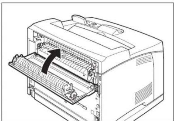
natural_image
Line drawing of a printer internal structure with a black arrow indicating the paper direction (no text or symbols present)IMPORTANT: Do not close the rear cover if the fuser unit is not installed. Forcibly closing it may damage the lever or the cover.
Transfer Roll Cartridge
This section explains about the transfer roll cartridge.
Caution on Handling the Transfer Roll Cartridge
The transfer roll cartridge is included as one of the regular replacement parts. Before replacing the transfer roll cartridge, open the box of the regular replacement parts and get the new transfer roll cartridge ready.
When handling the transfer roll cartridge, take note of the following points:

WARNING! Never throw an transfer roll cartridge into an open flame. It can cause an explosion and you can get burned.
Do not remove and reinsert the transfer roll cartridge in use.
When the message to replace the transfer roll cartridge appears, replace the transfer roll cartridge immediately. Otherwise, the printer will be forcibly stopped.

natural_image
Technical line drawing of a mechanical rod or lever assembly (no text or symbols)Replacing the Transfer Roll Cartridge
- Switch off the power of the printer.

natural_image
Line drawing of a printer with a close-up inset showing a button or socket (no text or symbols)- Remove any paper in the center output tray.
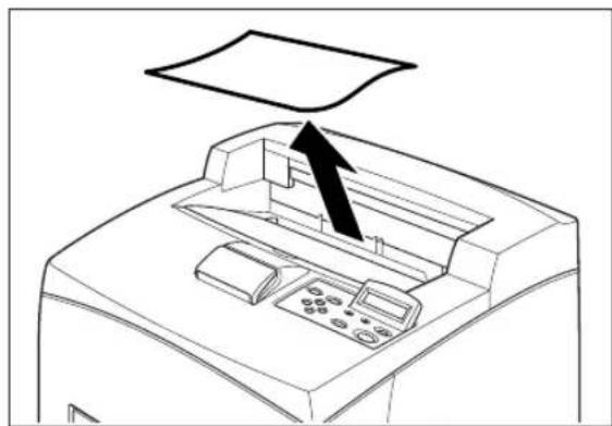
natural_image
Line drawing of a printer with a paper feeding into the top page (no text or symbols)- Open the top cover.
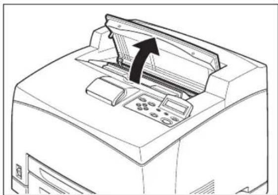
natural_image
Line drawing of a printer with an arrow indicating the paper's front cover (no text or symbols present)IMPORTANT: Do not touch any parts inside the printer.
- Hold the Toner Cartridge by the grip to pull it out slowly.
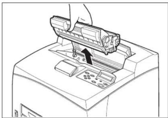
natural_image
Line drawing of a printer's front panel with a hand inserting a printer into the cover (no text or symbols)NOTE: To prevent the toner from dirtying the floor, lay a piece of paper on the floor before putting the Toner Cartridge down.
- Pull the 2 levers on the upper part of the transfer roll cartridge, then squeeze the 2 levers on the bottom of the transfer roll cartridge and pull it out slowly towards you.

natural_image
Technical line drawing of a mechanical assembly with no visible text or symbols
natural_image
Technical line drawing of a mechanical assembly with directional arrows indicating movement (no text or symbols)- Pick up the new transfer roll cartridge by the levers at both ends and slowly slot it in.

natural_image
Technical line drawing of a mechanical assembly with no visible text or symbols- Hold the Toner Cartridge by the grip and insert it into the slot inside the printer.

natural_image
Line drawing of a hand operating a printer with a control panel and drive mechanism (no text or symbols)IMPORTANT: Do not touch any parts inside the printer. Ensure that the Toner Cartridge is firmly set.
- Close the top cover securely.

natural_image
Line drawing of a printer with a paper airplane, showing front panel and control panel (no text or symbols)Feed Roll
This section explains about the feed roll.
Caution on Handling the Feed Roll
The feed roll is included as one of the regular replacement parts. Before replacing the feed roll, open the box of the regular replacement parts and get the new feed roll ready.
When handling the feed roll, take note of the following points:

CAUTION: Be sure to switch off and unplug the machine before accessing the interior of the machine for cleaning, maintenance, or fault clearance. Access to a live machine's interior can cause electric shock.
There are feed rolls inside the interior of the printer (2 in 2 locations, 4 in total), tray module (1 location) and paper tray (1 location).
Those rollers are periodic replacement parts. All feed rolls are recommended to be replaced.
Feed roll
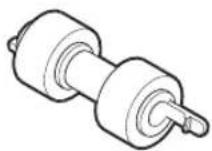
Inside the printer (2 locations) Tray module (1 location) Paper tray (1 location)

natural_image
Technical line drawing of a vehicle interior with gear and wheels (no text or symbols)
natural_image
Technical line drawing of a mechanical device casing with internal components and an arrow indicating a component (no text or symbols present)
natural_image
Technical line drawing of a computer chassis with internal compartments and a black arrow indicating a component (no text or symbols present)Replacing the Feed Roll
NOTE: The following procedure explains how to replace the feed roll of the paper tray. Follow the procedure here for replacing the feed roll of the tray module as well.
Feed roll at the paper tray
- Pull the paper tray out of the printer.

natural_image
Line drawing of a printer front panel with a black arrow pointing to the paper edge (no text or symbols present)NOTE: When replacing the feed roll of tray 2, pulled out both tray 1 and tray 2. The feed roll on tray modules can be replaced without pulling out the paper tray.
- While pushing down the shaft of the feed roll as shown in the diagram (1), widen the tab of the feed roll to loosen it (2) and then slowly remove the feed roll from the shaft on the paper tray (3).

- Hold the tab on the new feed roll as shown in the diagram and slowly push it into the shaft on the paper tray.


natural_image
Technical line drawing of a mechanical assembly with a directional arrow indicating motion (no text or symbols)By aligning the small tabs on the feed roll with the slots of the shaft, push the feed roll completely in so that the tab fits into the slot.
- Push the paper tray completely into the printer.

natural_image
Line drawing of a printer with control panel and paper feed (no text or symbols)Feed roll inside the printer
- Remove any paper in the center output tray.
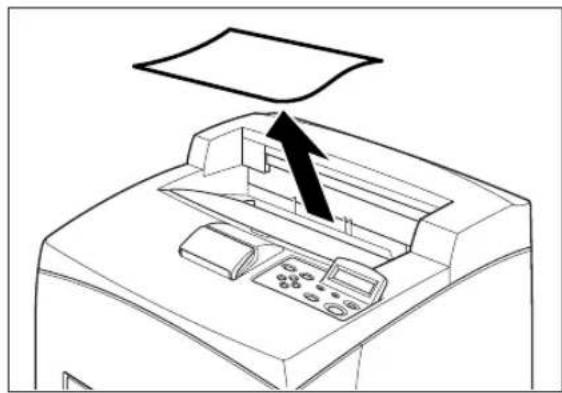
natural_image
Line drawing of a printer with an arrow pointing to the paper plane (no text or symbols present)- Open the top cover.

natural_image
Line drawing of a printer with an arrow indicating the paper's front cover (no text or symbols present)IMPORTANT: Do not touch any parts inside the printer.
- Hold the Toner Cartridge by the grip and pull it out slowly.

natural_image
Line drawing of a printer with an arrow indicating the paper's front cover (no text or symbols present)NOTE: To prevent the toner from dirtying the floor, lay a piece of paper on the floor before putting the Toner Cartridge down.
- While pushing down the shaft of the feed roll as shown in the diagram, widen the tab on the feed roll to loosen it (1) and then slowly remove the feed roll from the shaft of the paper tray (2).

- Hold the tab on the new feed roll as shown in the diagram and slowly push it into the shaft on the paper tray.
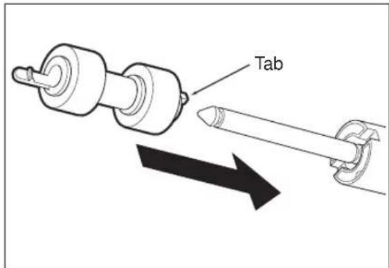

natural_image
Technical line drawing of a mechanical assembly with a pointed tool and circular component, showing no text or symbols.By aligning the small tabs on the feed roll with the slots of the shaft, push the feed roll completely in so that the tab fits into the slot.
- Hold the Toner Cartridge by the grip and insert it into the slot inside the printer.

natural_image
Line drawing of a printer with a hand operating the top panel (no text or symbols present)IMPORTANT: Do not touch any parts inside the printer. Ensure that the Toner Cartridge is firmly set.
Close the top cover securely.
Chapter 6
Optional Accessories
In this Chapter . . .
■ "Available Optional Accessories" on page 6-2
■ "Tray module (A4/550 sheets)" on page 6-2
■ "Offset catch tray" on page 6-17
■ "Rcar tray" on page 6-23
Available Optional Accessories
The following optional accessories are available for this printer.
Tray module (A4/550 sheets)
Install the tray module to the printer to use the paper tray (A4/550 sheets).

natural_image
Technical line drawing of a mechanical device with internal components (no text or symbols)NOTE: You can add up to two tray modules.
Installing/Uninstalling the Tray Module
The optional tray module (A4/550 sheets) is available for this printer.
You can add up to two tray modules.

CAUTION: Be sure to switch off the power and unplug the power cord from the outlet before carrying out the operations. If not, you might get an electric shock.
When lifting the machine, get a firm footing and bend your knees to avoid possible injuries to your back.
The weight of this printer, without the optional accessories, paper trays, consumables and paper, is 21.0 kg. Before moving the printer, you must uninstall the optional accessories first.
When lifting the printer, there should be 2 persons, 1 in front and 1 behind the printer, to firmly grip the recessed areas provided on both sides of the printer. Never try to lift the printer by gripping any other areas. Lifting the printer by gripping any other areas can cause the printer to fall and result in injuries.

natural_image
Line drawing of two hands holding a folder, viewed from the side (no text or symbols)Checking the contents of the tray module package
Before installing the tray module to the printer, ensure that you have all of the following items.
■ Tray module (A4/550 sheets)

natural_image
Technical line drawing of a mechanical device with internal components and a separate cluster of bracket-like parts (no text or symbols)Fasteners (four pieces) Tray module (A4/550 she

natural_image
Technical line drawing of a paper tray (A4/550 sheets) showing internal compartments and casing structure (no text or symbols on the diagram itself)Installing the Tray Module
- Place the tray module to be installed at the lowest level on a flat location.

natural_image
Technical line drawing of a mechanical device casing with internal compartments and mounting holes (no text or symbols)NOTE: Proceed to Step 5 if you are installing only one tray module.
- Lift up the tray module to be installed at the top level by holding the parts as shown in the diagram.

natural_image
Technical line drawing of a computer chassis with internal components and an arrow indicating direction (no text or symbols)- Align the front and back corners of the top and bottom tray modules, and slowly lower the top module so that the guide pins at the 4 corners of the bottom module fit into the holes at the base plate of the top module.

natural_image
Technical line drawing of a dual-tiered electronic device chassis with mounting holes and internal components (no text or symbols)IMPORTANT: The tray module must be lowered gently. Otherwise, the interior parts may be damaged.
- Insert the fasteners provided into the 2 locations inside of the tray module and 2 locations at the back of the tray module. Insert the fasteners securely.

natural_image
Technical diagram of a computer motherboard showing internal components and a magnified view of the internal structure (no text or symbols present)
natural_image
Technical line drawing of a mechanical assembly with an inset showing a cross-section detail (no text or symbols)- Switch off the power of the printer.
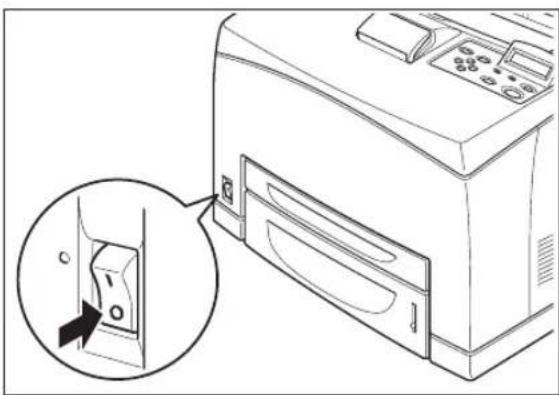
natural_image
Line drawing of a computer with an inset showing a close-up of a device's internal structure (no text or symbols)- Pull out the power cord from the power outlet and then the printer.

natural_image
Diagram showing connection between a computer tower and an electrical outlet, with no visible text or symbols- Remove any paper in the center output tray (1) and return the paper stopper to its original position if it's raised (2).

- Pull the paper tray out of the printer.
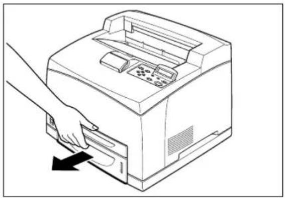
natural_image
Line drawing of a hand inserting a printer into a paper airplane (no text or symbols)- Lift up the printer by holding the recessed areas as shown in the diagram.
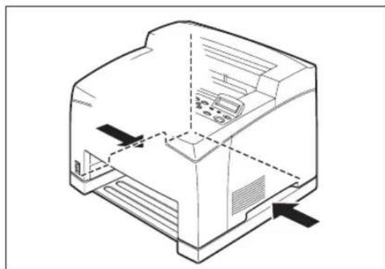
natural_image
Technical line drawing of a mechanical device with internal components and directional arrows (no text or symbols)- Align the corners of the printer and the tray modules, and lower the printer gently so that the guide pins at the 4 corners of the tray modules fit into the holes at the base plate of the printer.

natural_image
Technical line drawing of a printer internal structure with mounting holes and ventilation slots (no text or symbols)IMPORTANT: The printer must be lowered gently. Otherwise, the interior parts may be damaged.
- Insert the fasteners provided into the 2 locations inside and 2 locations at the back of the printer. Insert the fasteners securely.
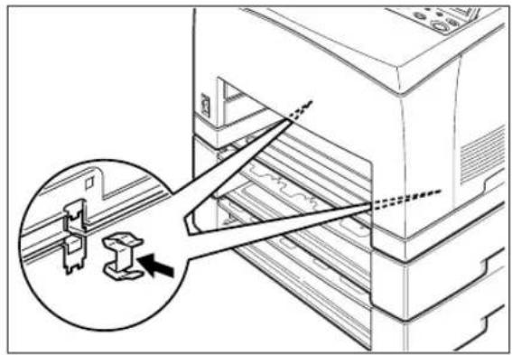

natural_image
Technical line drawing of a mechanical assembly with a magnified inset showing a bracket detail (no text or symbols)- Push the paper tray completely into the printer.
Refer to: See "Loading Paper" on page 1-11 for details on how to load paper into the paper tray.
Uninstalling the Tray Module
NOTE: The procedure here explains the uninstallation of two tray modules as an example. You can use the same procedure for uninstalling one tray module.
- Switch off the power of the printer.

natural_image
Diagram of a refrigerator drawer with an inset showing a close-up of the door handle (no text or symbols present)- Pull out the power cord from the power outlet and then the printer.

- Remove any paper in the center output tray (1) and return the paper stopper to its original position if it's raised (2).

- Pull the paper tray out of the printer.

natural_image
Diagram of a computer tower with arrows indicating file or data transfer (no text or symbols present)- Remove the fasteners found at the 2 locations inside and at the 2 locations at the back of the printer.


natural_image
Technical line drawing of a mechanical assembly with an inset showing a close-up of a component (no text or symbols present)- Lift up the printer by holding the recessed areas as shown in the diagram and then remove it from the tray modules.

natural_image
Technical line drawing of a printer or printer assembly with internal components and mounting base (no text or symbols)- Remove the fasteners found at the 2 locations inside the tray modules and at the 2 locations at the back of the tray modules.

natural_image
Technical diagram of a mechanical assembly with an inset showing a component being inserted into a housing (no text or symbols present)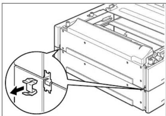
natural_image
Technical line drawing of a mechanical assembly with an inset showing a close-up of a component (no text or symbols present)- Lift up the top tray module by holding the recessed areas as shown in the diagram and then remove it from the bottom tray module.

natural_image
Technical line drawing of a computer chassis with internal components and an arrow indicating motion (no text or symbols)Paper trays
The following paper tray is available:
Paper tray (A4/550 sheets)
This is the same as the paper tray of the standard tray module (A4/550 sheets) for printers with a continuous print speed of 34 ppm. Use it in the standard tray module or the optional tray module (A4/550 sheets).
150 sheets

natural_image
Technical line drawing of a mechanical device casing with internal compartments and mounting brackets (no text or symbols)550 sheets
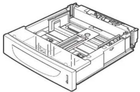
natural_image
Technical line drawing of a mechanical device with internal compartments and mounting holes (no text or symbols)Duplex module
Install this unit to the printer to enable 2 sided printing.

natural_image
Isometric line drawing of a rectangular electronic device with internal components and mounting ports (no text or symbols)Installing/Uninstalling the Duplex Module
You can install an optional duplex module to this printer.

CAUTION: Be sure to switch off the power and unplug the power cord from the outlet before carrying out the operations. If not, you might get an electric shock.
Installing the Duplex Module
- Switch off the power of the printer.

natural_image
Line drawing of a printer with an inset showing a close-up of its internal component (no text or symbols present)- Pull out the power cord from the power outlet and then the printer.

natural_image
Diagram showing cable connection between a computer tower and an electrical outlet (no text or symbols present)- Remove the rear cover of the printer after pushing the two tabs as shown in the diagram. Next, remove the connector cover of the printer as shown in the diagram.
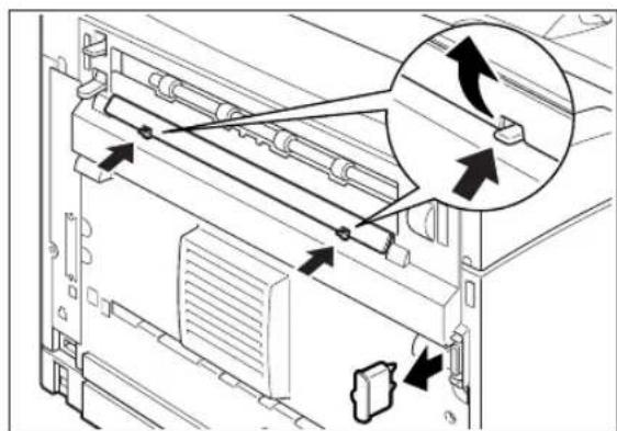
natural_image
Diagram of a computer tower internal structure with arrows indicating movement or assembly (no text or symbols present)- Insert the right and left tabs at the bottom of the duplex module into the holes at the back of the printer and then align the top part of the duplex module with the printer. Ensure that the connector of the duplex module is connected to the connector of the printer.
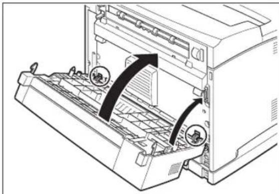
natural_image
Diagram of a printer's internal structure showing paper feed, paper tray, and paper holder (no text or symbols)- Tighten the screws at the both ends of the bottom of the duplex module.

natural_image
Technical line drawing of a server rack with a magnified inset showing internal components (no text or symbols)Uninstalling the Duplex Module
- Switch off the power of the printer.

natural_image
Line drawing of a microwave oven with a close-up inset showing the door panel (no text or symbols)- Pull out the power cord from the power outlet and then the printer.
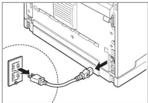
natural_image
Diagram showing connection between a computer tower and an electrical outlet, with no visible text or symbols- Loosen the screws at the both ends of the bottom of the duplex module.
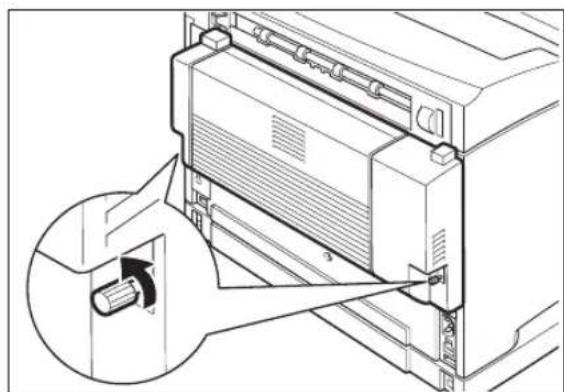
natural_image
Technical line drawing of a mechanical device with an inset showing a cable being inserted (no text or symbols present)- While supporting the duplex module with your hand, lift the lever at the top left hand side of the duplex module to unlock it and then tilt the top part of the duplex module away from the printer.

NOTE: You must support the duplex module with your hand as once it is unlocked. Otherwise, it may fall.
- While holding up the duplex module, remove the right and left tabs of the duplex module from the holes at the back of the printer.

natural_image
Diagram of a printer's internal structure showing paper feed and paper tray (no text or symbols)- Push in the cover and connector cover, which were removed during installation of the duplex module, until it clicks into the back of the printer.

natural_image
Technical line drawing of a computer tower internal structure showing ventilation ducts and drive slots (no text or symbols)Offset catch tray
Install this tray to the printer to enable print jobs to be output offset. Maximum capacity is 500 sheets of the standard paper.
The offset catch tray can be installed on the 34ppm printer.

natural_image
Technical line drawing of a mechanical component or bracket (no text or symbols)Installing/Uninstalling the Offset Catch Tray
You can install an optional offset catch tray to this printer.

CAUTION: Be sure to switch off the power and unplug the power cord from the outlet before carrying out the operations. If not, you might get an electric shock.
Installing the Offset Catch Tray
- Switch off the power of the printer.
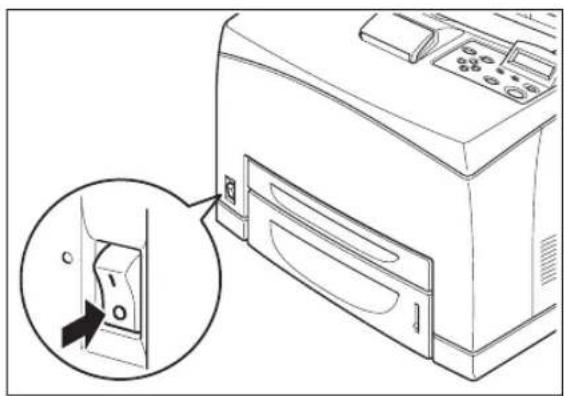
natural_image
Line drawing of a microwave oven with a close-up inset showing the outlet (no text or symbols)- Pull out the power cord from the power outlet and then the printer.

natural_image
Diagram showing cable connection between a computer tower and an electrical outlet (no text or symbols present)- Lift the second lever from the top left corner of the back of the printer.

natural_image
Technical line drawing of a printer internal structure with an inset showing a close-up of the front panel (no text or symbols present)- Open the rear cover.
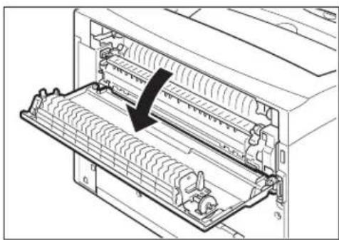
natural_image
Diagram of a computer rack with internal components and a black arrow indicating a specific part (no text or symbols present)NOTE: Do not touch any parts inside the printer.
- Untighten the right and left thumb screws as shown in the diagram to uninstall the top cover of the paper exit.

natural_image
Diagram of a printer internal structure with arrows indicating motion, no text or symbols present- Insert the right and left tabs of the offset catch tray into the holes at the top of the printer (1) and put it down to the top of the printer slowly (2).
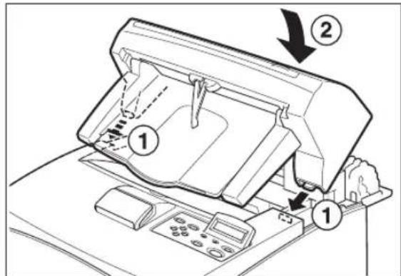
- Secure the screws at both ends of the bottom of the offset catch tray.

natural_image
Diagram of a printer or printer with internal structure and a magnified view showing a cable being inserted (no text or symbols present)- Pull out the extension tray.
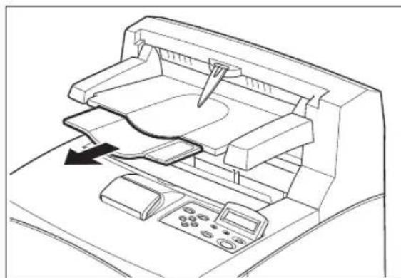
natural_image
Line drawing of a printer's internal structure with no visible text or symbols- Flip the stopper when print a thicker paper.

natural_image
Line drawing of a printer's internal structure with a hand operating the tray (no text or symbols)- Close the rear cover.
Uninstalling the Offset Catch Tray
- Switch off the power of the printer.

natural_image
Line drawing of a printer with an inset showing a close-up of its door panel (no text or symbols present)- Pull out the power cord from the power outlet and then the printer.

natural_image
Diagram showing connection between a computer tower and an electrical outlet, with a cable inserted (no text or symbols present)- Close the stopper and the extension tray of the offset catch tray.

natural_image
Line drawing of a printer with an open lid and control panel, showing internal components (no text or symbols)- Lift up the second lever (1) from the top left corner of the back of the printer to open the rear cover (2).

- Remove the screws on both sides of the offset catch tray (1), and while holding up the offset catch tray, remove the right and left tabs from the holes at the top of the printer (2).

- Fasten the right and left thumb screws of the top cover of the paper exit, which was removed during installation of the offset catch tray, into the holes at the top of the printer.

natural_image
Line drawing of a printer with an arrow pointing to the top panel (no text or symbols present)
natural_image
Technical line drawing of a printer internal structure with no visible text or symbolsRear tray
Install this tray to the printer to enable printouts to be output with the printed side up. Maximum capacity is 70 sheets of the standard paper.
The rear tray can be installed in the 34ppm printer.
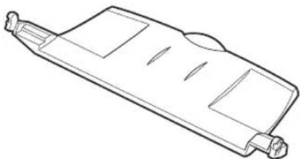
natural_image
Line drawing of a rectangular electronic component or panel with slots and connectors (no text or symbols)Installing/Uninstalling the Rear Tray
You can install an optional rear tray to this printer.

CAUTION: Be sure to switch off the power and unplug the power cord from the outlet before carrying out the operations. If not, you might get an electric shock.
Installing the Rear Tray
- Insert the right and left tabs of the rear tray into the holes at the back of the printer.
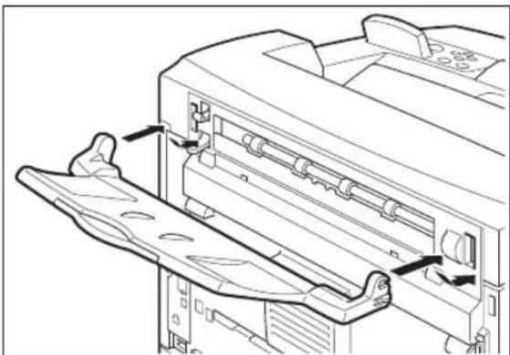
natural_image
Technical line drawing of a printer with internal components and directional arrows indicating assembly (no text or symbols)- Push up the lever as shown in the diagram (1) and pull out the extension tray (2).

Uninstalling the Rear Tray
- Close the extension tray.
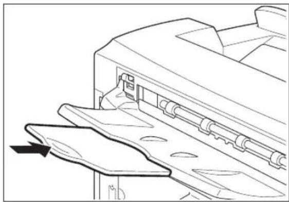
natural_image
Technical line drawing of a mechanical component with an arrow indicating direction (no text or symbols present)- While holding up the rear tray, remove the right and left tabs from the holes at the back of the printer.

natural_image
Technical line drawing of a printer or printer with internal components and mounting bracket (no text or symbols)- Push down the lever as shown in the diagram.
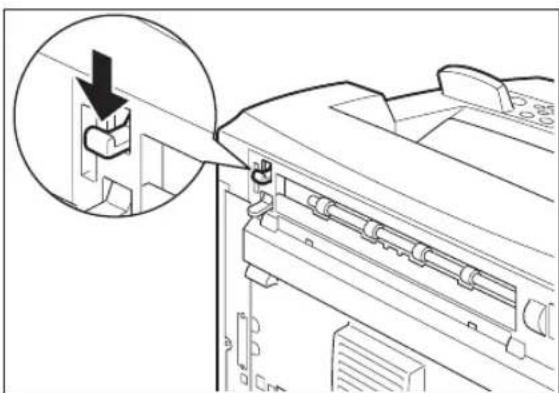
natural_image
Diagram of a printer's internal structure showing a paperclip inserted into a printer (no text or symbols present)Chapter 7
Understanding and Navigating the Control Panel Menus
In this Chapter . . .
■ "About this Chapter" on page 7-2
■ "Control Panel Features" on page 7-2
■ "Navigating the Control Panel Menus" on page 7-4
■ "Menu Structure" on page 7-6
■ "Job Library" on page 7-7
■ "Job Accounting" on page 7-9
■ "Paper Menu" on page 7-10
■ "Interface Menu" on page 7-13
■ "PS Menu" on page 7-16
■ "PCL Menu" on page 7-17
■ "System Menu" on page 7-20
■ "Quality Mcnu" on page 7-21
■ "Date/Time Menu" on page 7-22
■ "Functions Menu" on page 7-23
■ "FLASH Menu" on page 7-24
■ "DISK Menu" on page 7-25
About this Chapter
This chapter explains the control panel and its functions, and also demonstrates how to navigate through the control panel menus and submenus that allow you to view and change the printer settings. Web access to the printer is also discussed.
Control Panel Features
The control panel is located on the front of the printer, and contains the display, indicators, and pushbuttons that allow you to view and change the printer settings.
The figure below shows the control panel features.
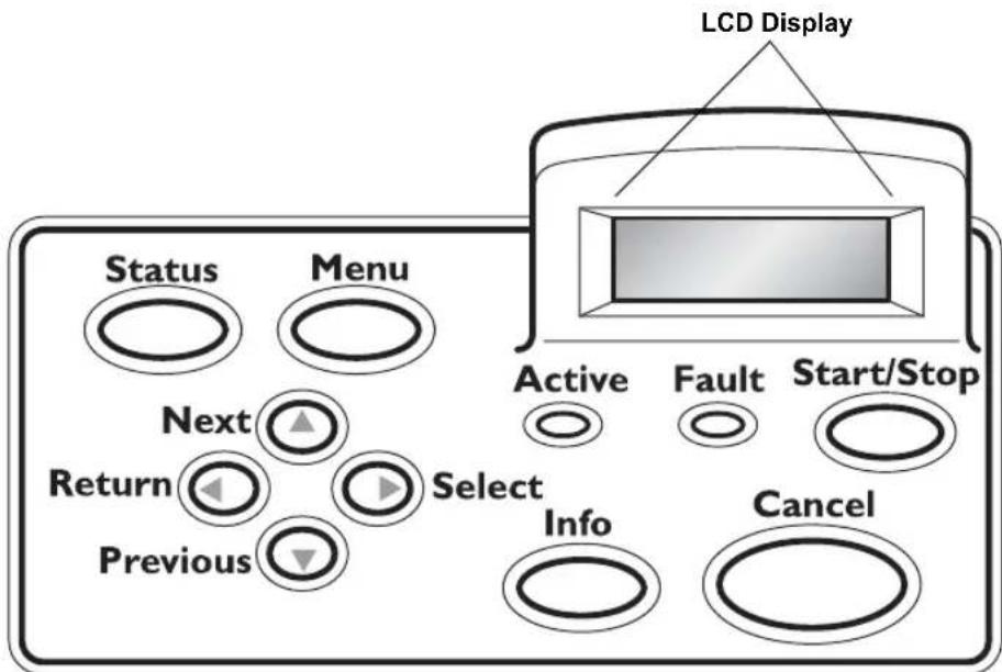
Figure 7-1: Control Panel.
LCD Display
The LCD display shows status and error messages that inform you of the current status of the printer, and also displays menus, submenus, and printer settings when you are in the menu system. The display contains two lines of text, each with a maximum of sixteen characters.
LED Indicators
The LED indicators also indicate printer status. The three indicators can each be on, off, or blinking, indicating different phases of printer operation. The table below explains the LED indicators.
| LED | COLOR | WHEN OFF | WHEN ON | WHEN BLINKING |
Start/Stop | Green Printer is NOT READY | Printer is READY N/A | ||
  | Green Printer is IDLE Printer is ACTIVE (processing a job) | Printer is WAITING(a partial job has been printed, and the printer is waiting for additional job data) | ||
  | Red Printer is not in error mode | There is an error that requires user intervention, such as a paper jam, a service call required, etc. | N/A | |
Pushbuttons
The control panel pushbuttons allow you to access and navigate menus, and also assist you in recovering from printer errors. The table below explains the functions of the eight pushbuttons.
| PUSHBUTTON FUNCTION | |
Start/Stop | START/STOP—Push this button to start or stop the printer, or to exit the menu system. |
Menu | MENU—Push this button to enter the menu system. |
 | NEXT—Push this button to move to the next menu, submenu, or setting within the same level of the menu structure. |
 | SELECT—Push this button to select the menu or submenu that is shown on the second line of the display or to choose and save the setting shown on the second line of the display. |
Cancel | CANCEL—Push this button to cancel an action. |
Status | STATUS—Push this button to enter the Status Menu and view the current status of the following items on the printer:MBF: Media Size, Media Type, LevelTray 1: Media Size, Media Type, LevelTray 2: Media Size, Media Type, LevelTray 3: Media Size, Media Type, LevelFacedown TrayToner |
 Previous Previous | PREVIOUS—Push this button to return to the previous menu, submenu, or option within the same level of the menu structure. |
R  | RETURN—Push this button to move up one level in the menu structure to the menu shown on the first line of the display. |
Navigating the Control Panel Menus
When you press the MENU button on the control panel, you enter the printer's menu system. At that point, the first line of the display contains the text "Menu", indicating that you are in the menu system. The second line of the display lists the active menu, which you can change by pressing the NEXT or PREVIOUS button.
Menu Paper Menu
If you press the NEXT button repeatedly, the second line of the display cycles through the main menus in the following order:
■Job Library Mcnu
■ Job Accounting Menu
■ Paper Menu
■ Interface Menu
■ PS Mcnu
■ PCL Menu
■ System Menu
■ Quality Menu
■ Color Menu
■ Functions Menu
■ Flash Menu
■ Status
NOTE: Additional menus and submenus may appear in the printer menu system when other options are installed.
The following figure shows the sequence of pushbuttons and display messages that would allow you to change the number of copies printed. This example illustrates the basic relationship between menus and submenus and demonstrates how the NEXT, PREVIOUS, SELECT, and RETURN buttons help you to navigate through the menus.
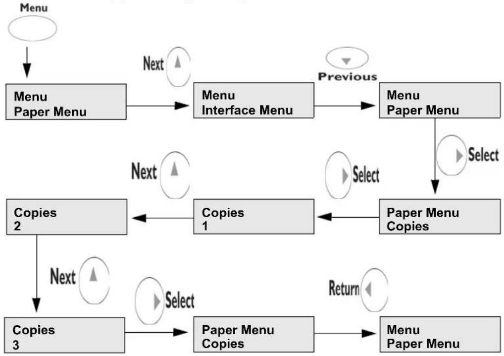
flowchart
graph TD
    A["Menu"] --> B["Menu Paper Menu"]
    B --> C["Menu Interface Menu"]
    C --> D["Menu Paper Menu"]
    D --> E["Paper Menu Copies"]
    E --> F["Copies 1"]
    F --> G["Copies 2"]
    G --> H["Copies 3"]
    H --> I["Paper Menu Copies"]
    I --> J["Menu Paper Menu"]
    style A fill:#fff,stroke:#000
    style B fill:#ccc,stroke:#000
    style C fill:#ccc,stroke:#000
    style D fill:#ccc,stroke:#000
    style E fill:#ccc,stroke:#000
    style F fill:#ccc,stroke:#000
    style G fill:#ccc,stroke:#000
    style H fill:#ccc,stroke:#000
    style I fill:#ccc,stroke:#000
    style J fill:#ccc,stroke:#000
    subgraph "Previous"
        C
        D
        E
        F
        G
        H
        I
    end
    subgraph "Select"
        E
        F
        G
        H
        I
    end
    subgraph "Return"
        J
    end
Figure 7-2: Navigating the Paper Menu.
- Press the MENU button on the control panel.
- Press the NEXT button until the text "Paper Menu" is shown on the second line of the display.
- Press the SELECT button to enter the paper menu.
- Press the NEXT button until the text "Copies" is shown on the second line of the display.
- Press the SELECT button to enter the copies submenu.
- Press the NEXT or PREVIOUS button to increase or decrease the number of copies printed.
- Press the SELECT button to save this setting.
- Press the START/STOP button to exit the menu system.
Menu Structure
The following figure shows the structure of the control panel main menus and submenus.
| Job Library Print Delete | Job Accounting Enabled Print Info Reset Info | Paper Menu Copies Duplex Duplex Bind Default Source Output Tray Media Size/Type MBF Tray 1 Tray 2 Tray 3 (optional) Tray Linking Blank Pages Output Linking Gloss Level Auto Resize Separator Page Custom Size Unit | Interface Menu Port Parallel Network Card 1 USB Parallel Setup Interpreter Format Mode Delay Out Close Binary PS Network 1Setup Interpreter Format Network Address IP Address Subnet Mask Default Router LPD Banner DHCP Delay Out Close Host Name mDNS Local Link mDNS Host Name mDNS Svc Name Multi-Session AppleTalk Current Zone Preferred Zone Binary PS Connection Speed Spooling USB Setup Interpreter Format Delay Out Close Binary PS |
| PS Menu Print PS Errors | PCL Menu Orientation Font Source Font Number Pitch Symbol Set Macro Filter Lines Per Page CR Mode LF Mode FF Mode Print Area Parameter Values Paper Source Paper Size | System Menu Display Language Power Saver Wait Timeout Job Timeout Jam Recovery Hex Print Toner Low Page Compression Intellifilter | Flash Print Delete Format Flash Flash Summary |
| Quality Menu Resolution Print Density | Date/Time Menu Month Day Year Hour Minute Second Offset from GMT Hours Minutes | Functions Reset Printer Print Summary Print Demo Print Fonts |
Figure 7-3: Printer Menu Structure.
NOTE: Additional menus and submenus may appear in the printer menu system when other options are installed.
Status Menu
In addition to the main menus listed above, the printer also provides a status menu that allows you to view the current printer settings. Push the STATUS button to enter the Status Menu.
Status Menu
Tray 1
Media Size
Media Type
Level
Tray 2
Media Size
Media Type
Level
Tray 3 (Optional)
Media Size
Media Type
Level
Face Down Tray
Offset Tray
Toner
Job Library
- Press the MENU button on the control panel.
- Press the NEXT button until the text "Job Library Menu" is shown on the second line of the display.
- Press the SELECT button to enter the Job Library menu.
- Press the NEXT button to move through the submenus: Print or Delete.
- Press the SELECT button to enter a submenu.
Use the procedures in the following table to access and change the Job Library settings.
| Submenu Default | Setting | Available Settings Procedure for Changing Setting |
| Print Print | User Folder 1 | |
| Print Print | Job1 | |
| Job NamePIN | This step is necessary if the job is a PRIVATE job. | |
| Print Job Name | Copies -Select 1-99 | |
| Print Job Name | Copies | |
| Print Printing | Playback | |
| Delete Delete | (To delete a saved job) | |
| DeleteUser Folder 1 | ||
| DeleteJob1 | ||
| Job NamePIN | This step is necessary if the job is a PRIVATE job. |
Job Library Errors
When a Job Library error occurs, the following message will be displayed:
JOBLIB Error XX
Press Start
This is a continuable-fault, which means the START key must be pressed to allow operations to continue. If the current job is aborted as a result of the error, the message "Canceling Job" may be displayed after START is pressed. "XX" in the error display above is an error code. The error codes for this message are:
■ 01 – Data stream was missing a Job Name specification. (Job will be aborted.)
■ 02 – Data stream was missing a User Name specification. (Job will be aborted.)
■03 – Data stream was missing a PIN specification. (Job will be aborted.)
■ 04 – Attempted to overwrite a PRIVATE job, but PIN did not match. (Job will be aborted.)
■ 05 – Insufficient storage. (Job will be aborted only if it is a PRIVATE job.)
Job Accounting
The Job Accounting Menu provides access to functions and settings related to this feature. Use the following procedure to enter the Job Accounting Menu to change the settings or access the functions:
- Press the MENU button on the control panel.
- Press the NEXT button until the text "Job Accounting Menu" is shown on the second line of the display.
- Press the SELECT button to enter the Job Accounting Menu.
- Press the NEXT button to move through the submenus: Enable, Print Info, Reset Info.
- Press the SELECT button to enter a submenu.
Use the procedures in the following table to access and change the Job Accounting settings.
| SubMenu Default Settings | Available Settings | Procedure for Changing Setting |
| Enabled No Yes | No | 1. Press NEXT or PREVIOUS to scroll through Yes or No options.2. Press SELECT to choose Yes to turn on this function. |
| Print Info 1. Press SELECT to begin printing the Job | Accounting Summary Report. | |
| Reset Info 1. Press SELECT to reset the Job Accounting | Information. This will delete all stored information related to jobs received by the printer. | |
Paper Menu
The Paper Menu provides access to the printer settings for various paper-handling functions. Use the following procedure to enter the paper menu:
- Press the MENU button on the control panel.
- Press the NEXT button until the text "Paper Menu" is shown on the second line of the display.
- Press the SELECT button to enter the Paper Menu.
- Press the NEXT button to move through the submenus.
Use the procedures in the following table to access and change the printer paper-handling settings:
| Submenus Default | Setting | Available Settings Procedure for Changing Setting | ||
| CopiesThis submenu allows you to change the number of copies printed. | 1 Numbers 1 – | 999 1. Press NEXT or PREVIOUS to increase or decrease the number of copies printed.2. Press SELECT to save this setting. | ||
| DuplexThis submenu allows you to turn the duplex on or off. | Off On/Off 1. Press NEXT or PREVIOUS to toggle between ON and OFF.2. Press SELECT to save this setting. | |||
| Duplex BindThis submenu allows you to choose between LEF (Long Edge Feed) and SEF (Short Edge Feed). | LEF LEF/SEF | 1. Press NEXT or PREVIOUS to toggle between LEF and SEF.2. Press SELECT to save this setting. | ||
| Default SourceThis submenu allows you to choose a default paper source from a list of all installed sources. | Tray 1 MBF | Tray 1Tray 2 (optional)Tray 3 (optional) | 1. Press NEXT or PREVIOUS to scroll through the list of available sources of paper.2. Press SELECT to set a source as the default. | |
| Output TrayThis submenu allows you to select the paper output locations. | Off On | Off | 1. Press NEXT or PREVIOUS to toggle between ON and OFF.2. Press SELECT to save this setting. | |
| Submenus Default | Setting | Available Settings Procedure | for Changing Setting | |
| Media Size/TypeThis submenu allows you to set the media size and type for all the trays. | MBFSize: LetterSEFType: PlainCustom SizeTray 1Type: PlainTray 2(optional)Type: PlainTray 3(optional)Type: PlainTray4(optional) | SizeMBF:Letter, B5,A5, A6,Statement,Executive,C5EnvelopeDLEnvelope,Com10Envelope,MonarchEnvelope,Legal,Folio, A4SEF,Letter SEFOtherTrays:Legal,Folio,Letter, A4,Executive,B5, A5 | TypeMBF: Plain,Transparency,Prepunched,Letterhead,Colored,Preprinted,Bond,Label, CardStock,Postcard,Envelope,Other, Thick 1, Thick 2,Thick 3Other Trays:Plain,Transparency,Prepunched,Letterhead,Colored,Preprinted,Bond, OtherCard Stock,Thick 1,Thick 2 | Press NEXT or PREVIOUS to scroll through the list of available sources of paper.Press SELECT to choose a tray.Press NEXT or PREVIOUS to toggle between MEDIA SIZE and MEDIA TYPE.Press SELECT to choose either.Press NEXT or PREVIOUS to scroll through the available sizes or types.Press SELECT to set a size or type. |
| Tray LinkingThis submenu allows you to turn the tray linking function on or off. | On On | Off | Press NEXT or PREVIOUS to toggle between ON and OFF.Press SELECT to save this setting. | |
| Blank PagesThis submenu allows you to choose to either print or not print blank pages of a document. | Print Print | Do Not Print | Press NEXT or PREVIOUS to toggle between PRINT and DO NOT PRINT.Press SELECT to save this setting. | |
| Output Linking Off | On | Off | Press NEXT or PREVIOUS to toggle between ON and OFF.Press SELECT to save this setting. | |
| Submenus Default | Setting | Available Settings Procedure for Changing Setting | |
| Auto ResizeThis menu will scale the output of a PS job to the size selected. It does not scale a PCL job. | Off On | Off | 1. Press NEXT or PREVIOUS to toggle between ON and OFF.2. Press SELECT to save this setting. |
| Separator PagePrints a blank page between print jobs. | Off On | Off | 1. Press NEXT or PREVIOUS to toggle between ON and OFF.2. Press SELECT to save this setting. |
| Custom Size UnitThis menu is used to set the unit of measurement for the Custom Paper Size feature. | Inches Inches | Millimeters | 1. Press NEXT or PREVIOUS to toggle between INCHES and MILLIMETERS.2. Press SELECT to save this setting. |
Interface Menu
The Interface Menu provides access to the printer interface settings. Use the following procedure to enter the interface menu:
- Press the MENU button on the control panel.
- Press the NEXT button until the text "Interface Menu" is shown on the second line of the display.
- Press the SELECT button to enter the interface menu.
- Press the NEXT button to move through the submenus: Port, Parallel Setup, Network 1 Setup, Spooling, and USB Setup.
Use the procedures in the following table to access and change the printer interface settings:
| Submenus Default Setting Available | Settings | Procedure for Changing Setting | |
| PortThis submenu allows you to enable the type of interface. | Parallel:OnNetwork Card1:OnUSB:On | Parallel:On, OffNetwork Card1:On, OffUSB:On, Off | 1. Press NEXT or PREVIOUS to toggle between PARALLEL, NETWORK CARD 1 and USB.2. Press SELECT to save this setting. |
| Parallel SetupThis submenu allows you to set up the parallel interface. | Interpreter:Auto SwitchFormat:RawMode:BidirectionalDelay OutClose:OffBinary PS:Off | Interpreter:Auto SwitchPCLPostScript 3Format:RawNormalBinaryMode:BidirectionalStandardDelay OutClose:OffOnBinary PS:OffOn | 1. Press NEXT or PREVIOUS to scroll through the INTERPRETER, FORMAT, MODE, DELAY OUT CLOSE, and BINARY PS submenus.2. Press SELECT to choose a submenu.3. Press NEXT or PREVIOUS to scroll through the settings.4. Press SELECT to choose and save a setting. |
| Network 1 SetupThis submenu allows you to set up the Network interface. | Interpreter:Auto SwitchFormat:RawNetworkAddress:IP Address:(user-specified)Subnet Mask:(user-specified)Default Router:(user-specified)LPD Banner:OnDHCP:OffDelay OutClose:OffHost Name:Character string0-31 charactersmDNS:OnLocal Link:0.0.0.0mDNS HostName:Product name and last 3 hex byte values of NetworkAddressmDNS SvcName:Product name and last 3 hex byte values of NetworkAddressMulit-Session:OnAppleTalk:Current Zone:Preferred Zone:Binary PS:OffConnectionSpeed: | Interpreter:Auto SwitchPCLPostScript 3Format:RawNormalBinaryNetworkAddress:IP Address:(user-specified)Subnet Mask:(user-specified)Default Router:(user-specified)LPD Banner:On, OffDHCP:Off, OnDelay OutClose:Off, OnHost Name:mDNS:On, OffLocal Link:mDNS HostName:mDNS SvcName:Mulit-Session:On, OffAppleTalk:Current Zone:Preferred Zone:Binary PS:Off, OnConnectionSpeed: | 1. Press NEXT or PREVIOUS to move among the submenus.2. Press SELECT to choose a submenu.3. Press NEXT or PREVIOUS to scroll through the settings.4. Press SELECT to save this setting. |
| Submenus Default Setting | Setting Available | Settings | Procedure for Changing Setting |
| SpoolingThe spool ing feature allows print jobs to be automatically spooled to the Flash memory. This is a diagnostic tool. | Start Spooling:Spool and PrintSpool OnlyStop Spooling:Disables spoolingPlayback:Used to read a file from the user FlashDelete:Use to delete a spool file from the User Flash.Destination:User Flash Disk | 1. Press NEXT or PREVIOUS to scroll through the SPOOLING submenus.2. Press SELECT to choose a submenu.3. Press NEXT or PREVIOUS to scroll through the settings.4. Press SELECT to save this setting. | |
| USB SetupThis submenu allows you to set up the USB interface. | Interpreter:Auto SwitchFormat:RawDelay OutClose:OffBinary PS:Off | Interpreter:Auto SwitchPCLPostScript 3Format:RawNormalBinardDelay OutClose:OffOnBinary PS:OffOn | 1. Press NEXT or PREVIOUS to scroll through the INTERPRETER, FORMAT, DELAY OUT CLOSE, and BINARY PS submenus.2. Press SELECT to choose a submenu.3. Press NEXT or PREVIOUS to scroll through the settings.4. Press SELECT to save this setting. |
PS Menu
The PS Menu provides access to the PostScript settings. Use the following procedure to enter the PS Menu:
- Press the MENU button on the control panel.
- Press the NEXT button until the text "PS Menu" is shown on the second line of the display.
- Press the SELECT button to enter the PS menu.
- Press the NEXT button to move through the submenus: Print PS Errors, and Manual Feed TO.
- Press the SELECT button to enter a submenu.
Use the procedures in the following table to access and change the PostScript settings:
| Submenus | Default Setting | Available Settings | Procedure for Changing Settings |
| Print PS ErrorsThis submenu allows you to choose to either print or not print PS errors. | Off On | Off | 1. Press NEXT or PREVIOUS to toggle between ON (print) and OFF (do not print).2. Press SELECT to save this setting. |
PCL Menu
The PCL Menu provides access to the PCL settings. Use the following procedure to enter the PCL menu:
- Press the MENU button on the control panel.
- Press the NEXT button until the text "PCL Menu" is shown on the second line of the display.
- Press the SELECT button to enter the PCL menu.
- Press the NEXT button to move through the submcnus: Orientation, Font Source, Font Number, Pitch, Symbol Set, Macro Filter, Lines Per Page, CR Mode, LF Mode, FF Mode, and Print Area.
- Press the SELECT button to enter a submenu.
Use the procedures in the following table to access and change the PCL settings:
| Submenus | Default Setting | Available Settings | Procedure for Changing Setting |
| OrientationThis submenu allows you to choose the orientation of the page. | Portrait Portrait | Landscape | 1. Press NEXT or PREVIOUS to toggle between PORTRAIT and LANDSCAPE.2. Press SELECT to choose and save an orientation. |
| Font SourceThis submenu allows you to choose a font source. | Internal Internal | 1. Press NEXT or PREVIOUS to | scroll through the available font sources.2. Press SELECT to choose and set a source. |
| Font NumberThis submenu allows you to set the font number. | 0 Numbers 0-53 | 1. Press NEXT or PREVIOUS to | increase or decrease the font number.2. Press SELECT to save this setting. |
| PitchThis submenu allows you to change the pitch of text. | 10.00 | 0.08 – 100.00 | 1. Press NEXT or PREVIOUS to increase or decrease the pitch.2. Press SELECT to save this setting. |
| Submenus | Default Setting | Available Settings | Procedure for Changing Setting | |
| Symbol SetThis submenu allows you to choose a symbol set. | 10U:PC-8CP437 | 10U:PC-8CP43711U:PC-8 D/N12U:PC-85017U:PC-8529T:PC-Turkish19U:WIN Latin19E:WIN Latin25T:WIN Latin57J:Desk Top10J:PS Text13J:Ventura Intl14J:Ventura US6J:MicrosoftPub8M:Math-8PS:Math6M:VenturaMath | 15U:Pi Font1U: Legal1E: ISO4 UK0U:ISO6 ASCII0S:ISO11Swedish0I:ISO15 Italian2S:ISO17Spanish1G:ISO21German0D:ISO60Norwegian1F:ISO69 French9U:WIN3.0Latin18U:Roman 80N:ISO 8859-12N:ISO 8859-25N:ISO 8859-5 | 1. Press NEXT or PREVIOUS to scroll through the available symbol sets.2. Press SELECT to choose and set a symbol set. |
| Macro FilterThis submenu allows you to turn the macro filter on or off. | Off On | Off | 1. Press NEXT or PREVIOUS to toggle between ON and OFF.2. Press SELECT to save this setting. | |
| Lines Per PageThis submenu allows you to change the number of lines per page. | 60 5 – 128 1. Press NEXT or PREVIOUS to | increase or decrease the lines per page.2. Press SELECT to save this setting. | ||
| CR ModeThis submenu allows you top define the action prompted by a carriage return—a carriage return equals either a carriage return alone, or a carriage return and a line feed together. | CR = CR CR = CR | CR = CR/LF | 1. Press NEXT or PREVIOUS to choose from CR=CR or CR=CR/LF.2. Press SELECT to save this setting. | |
| LF ModeThis submenu allows you to define the action prompted by a line feed-a line feed equals either a line feed alone or a carriage return and a line feed together. | LF = LF LF = LF | LF = CR/LF | 1. Press NEXT or PREVIOUS to choose from LF=LF or LF=CR/LF.2. Press SELECT to save this setting. | |
| FF ModeThis submenu allows you to define the action prompted by a form feed-a form feed equals either a form feed alone or a carriage return and a form feed together. | FF = FF FF = FF | FF = CR/FF | 1. Press NEXT or PREVIOUS to choose from FF=FF or FF=CR/FF.2. Press SELECT to save this setting. | |
| Print AreaThis submenu allows you to set the print area. | Normal Normal | Expanded | 1. Press NEXT or PREVIOUS to toggle between the NORMAL and EXPANDED settings.2. Press SELECT to save this setting. | |
| Parameter Values Paper Source:Paper Size:Executive | Paper Source:Tray 1 (=0001)Tray 2 (=0004 - optional tray)Tray 3 (=0005 - optional tray)Tray 3 (=00065-optional tray)Auto-select (=0007) | Paper Size:Executive(=0001)Letter (=0002)Legal (=0003)Statement(=0004)Folio (=0005)A6 (=0024)A5 (=0025)A4 (=0026)B5 (=0045)MonarchEnvelope(=0080)Com10 Envelope(=0081)DL Envelope(=0090)CS Envelope(=0091) | 1. Press NEXT or PREVIOUS to toggle between the PAPER SOURCE and PAPER SIZE submenus.2. Press SELECT to choose a submenu.3. Press NEXT or PREVIOUS to scroll through the settings.4. Press SELECT to save this setting. | |
System Menu
The system menu provides access to system settings. Use the following procedure to enter the system menu:
- Press the MENU button on the control panel.
- Press the NEXT button until the text "System Menu" is shown on the second line of the display.
- Press the SELECT button to enter the system menu.
- Press the NEXT button to move through the submenus: Factory Defaults, Display Language, Power Saver, Wait Timeout, Job Timeout, Jam Recovery, Hex Print, Toner Low, Page Compression, and Intellifilter.
- Press the SELECT button to enter a submenu.
Use the procedures in the following table to access and change the system settings:
| Submenus Default Setting Available | Settings | Procedure for Changing Setting | |
| Factory DefaultsThis submenu allows you to reset the printer to U.S. or Non-U.S.factory defaults. | U.S. U.S. | Non-U.S. | 1. Press NEXT or PREVIOUS to toggle between U.S. and NON-U.S.2. Press SELECT to choose and set the factory defaults. |
| Display LanguageThis submenu allows you to change the language of the display messages. | English English | Francais (French)Deutsch (German)Italiano (Italian)Espanol (Spanish) | 1. Press NEXT or PREVIOUS to scroll through the available languages: English, French (Francais), German (Deutsch), Italian (Italiano), or Spanish (Espanol).2. Press SELECT to choose and set the language. |
| Power Saver | 15 | 1 – 60 | 1. Press NEXT or PREVIOUS to increase or decrease the digit.2. Press SELECT to save this setting. |
| Wait TimeoutThis submenu allows you to increase or decrease the length of time (in seconds) that the printer will remain in the waiting state—a job is being processed, no end-of-file has been detected, and there is no more data to process. This setting applies to both PCL and PostScript print jobs. | 00020 0 – 99999 | 1. Press NEXT or PREVIOUS to increase or decrease each digit of the five-digit number.2. Press SELECT set one digit and move to the next digit.3. Press SELECT after changing the last digit to save this setting. | |
| Job TimeoutThis submenu allows you to increase or decrease the time limit (in seconds) for PostScript jobs. A 0 setting indicates no timeout. This setting applies only to PostScript jobs. | 00000 0 – 99999 | 1. Press NEXT or PREVIOUS to increase or decrease each digit of the five-digit number.2. Press SELECT set one digit and move to the next digit.3. Press SELECT after changing the last digit to save this setting. | |
| Jam RecoveryThis submenu allows you to turn jam recovery on or off. | On On | Off | 1. Press NEXT or PREVIOUS to toggle between ON and OFF.2. Press SELECT to save this setting. |
| Hex PrintThis submenu allows you to print hexadecimal characters. | Off On | Off | 1. Press NEXT or PREVIOUS to toggle between ON and OFF.2. Press SELECT to save this setting. |
| Toner Low Stop Stop | Continue | 1. Press NEXT or PREVIOUS to toggle between STOP and CONTINUE.2. Press SELECT to save this setting. | |
| Page Compression On On | Off | 1. Press NEXT or PREVIOUS to toggle between ON and OFF.2. Press SELECT to save this setting. | |
| IntellifilterThis submenu allows you to turn the Intellifilter feature on or off. | On On | Off | 1. Press NEXT or PREVIOUS to toggle between ON and OFF.2. Press SELECT to save this setting. |
Quality Menu
The Quality Menu provides access to the printer settings that are related to print quality. Use the following procedure to enter the Quality Menu:
- Press the MENU button on the control panel.
- Press the NEXT button until the text "Quality Menu" is shown on the second line of the display.
- Press the SELECT button to enter the system menu.
- Press the NEXT button to move through the submenus: Resolution and Print Density. Press the SELECT button to enter a submenu.
Use the procedures in the following table to access and change the quality menu settings:
| Submenus Default Setting Available | Settings | Procedure for Changing Setting | |
| ResolutionThis submenu allows you to set the resolution (dpi). | 600 dpi 600 dpi | 1200 dpi | 1. Press NEXT or PREVIOUS to scroll through the available resolutions.2. Press SELECT to choose and set the dpi. |
| Print Density | 5 | 1 – 7 | 1. Press NEXT or PREVIOUS to increase or decrease the digit.2. Press SELECT to save this setting. |
Date/Time Menu
The Date/Time Menu provides access to the printer settings that are related to print quality. Use the following procedure to enter the Date/Time Menu:
- Press the MENU button on the control panel.
- Press the NEXT button until the text "Date/Time Menu" is shown on the second line of the display.
- Press the SELECT button to enter the menu.
- Press the NEXT button to move through the submenus: Month, Day, Year, Hour, Minute, Second, and Offset from GMT. Press the SELECT button to enter a submenu.
Use the procedures in the following table to access and change the Date/Time menu settings:
| Submenus Available Settings | Procedure for Changing Setting | |
| MonthThis submenu allows you to set the current month. | January thru December 1. Press | NEXT or PREVIOUS to scroll through the months.2. Press SELECT to choose and set the month. |
| DayThis submenu allows you to set the current day. | Monday – Sunday 1. Press NEXT | or PREVIOUS to scroll through the days.2. Press SELECT to choose and set the day. |
| YearThis submenu allows you to set the current year. | 2000 – 2099 1. Press NEXT or PREVIOUS to scroll through the years.2. Press SELECT to choose and set the year. | |
| HourThis submenu allows you to set the current hour. | 1-12 1. Press NEXT or PREVIOUS to scroll through the hours.2. Press SELECT to choose and set the hour. | |
| MinuteThis submenu allows you to set the current minute. | 1 – 59 1. Press NEXT or PREVIOUS to scroll through the minutes.2. Press SELECT to choose and set the minute. | |
| SecondThis submenu allows you to set the time in seconds. | 1 – 59 1. Press NEXT or PREVIOUS to scroll through the seconds.2. Press SELECT to choose and set the second. | |
| Offset from GMTThis submenu allows you to set time for a different time zone in hours, minutes and seconds. | -12 through + 12 1. Press NEXT | or PREVIOUS to scroll through the submenus.2. Press SELECT to choose and set the hours, minutes or seconds. |
Functions Menu
The Functions Menu provides access to several printer functions that can supply you with information about the printer and its settings. Use the following procedure to enter the Functions Menu:
- Press the MENU button on the control panel.
- Press the NEXT button until the text "Functions Menu" is shown on the second line of the display.
- Press the SELECT button to enter the system menu.
- Press the NEXT button to move through the available functions: Reset Printer, Print Summary, Print Demo, and Print Fonts.
Use the procedures in the following table to execute the functions:
| Functions Procedure for Executing Function | |
| Reset PrinterThis function resets the printer. | Press SELECT to reset the printer. |
| Print SummaryThis function prints a list of all printer settings: | Press SELECT to print a summary of the printer settings. |
| Print DemoThis function allows you to print a demo page. | Press SELECT to print a Demo Page. |
| Print FontsThis function allows you to print Postscript or PCL font lists. | 1. Press NEXT or PREVIOUS to toggle between POSTSCRIPT and PCL.2. Press SELECT to select and print the specific fonts list. |
FLASH Menu
The FLASH Menu provides access to the printer settings that are related to the FLASH DIMM. This menu appears when a User Flash is installed in the printer. Use the following procedure to enter the FLASH Menu:
- Press the MENU button on the control panel.
- Press the NEXT button until the text "FLASH Menu" is shown on the second line of the display.
- Press the SELECT button to enter the system menu.
- Press the NEXT button to move through the submenus: Print, Delete, Format FLASH, and FLASH summary.
- Press the SELECT button to enter a submenu.
Use the procedures in the following table to access and change the Flash menu settings:
| Submenus Procedure for Changing Setting | |
| PrintThis selection will read the selected file from FLASH and print it as if it were being received from one of the input ports. | 1. Press NEXT or PREVIOUS to scroll through the files.2. Press SELECT to choose and print the file. |
| DeleteThis selection will delete the selected disk file or directory from the FLASH DIMM. To delete an entire directory, you must first delete all the files within that directory. | 1. Press NEXT or PREVIOUS to scroll through the files.2. Press SELECT to choose and delete the file. |
| Format FlashThis selection will reformat the FLASH DIMM. | 1. Press SELECT to reformat the FLASH DIMM. |
| Flash SummaryThis selection will print a page containing information about the installed FLASH DIMM including a list of all the current existing files and directories. | 1. Press SELECT to print the FLASH summary. |

WARNING! All files on the FLASH DIMM will be deleted if the Format FLASH function is selected.
DISK Menu
NOTE: This menu selection will only appear if an optional hard disk drive has been installed. Consult the documentation that came with your hard disk drive for detailed installation and usage instructions.
The Disk Menu provides access to the printer settings that are related to the optional Hard Disk. Use the following procedure to enter the Disk Menu:
- Press the MENU button on the control panel.
- Press the NEXT button until the text "Disk Menu" is shown on the second line of the display.
- Press the SELECT button to enter the system menu.
- Press the NEXT button to move through the submenus: Print, Delete, Format Disk, and Disk Summary.
- Press the SELECT button to enter a submenu.
Use the procedures in the following table to access and change the Disk menu settings:
| Submenus Procedure for Changing Setting | |
| PrintThis selection will read the selected file from Disk and print it as if it were being received from one of the input ports. | 1. Press NEXT or PREVIOUS to scroll through the files.2. Press SELECT to choose and print the file. |
| DeleteThis selection will delete the selected disk file or directory from the hard disk. To delete an entire directory, you must first delete all the files within that directory. | 1. Press NEXT or PREVIOUS to scroll through the files.2. Press SELECT to choose and delete the file. |
| Format DiskThis selection will reformat the hard disk. | 1. Press SELECT to reformat the hard disk. |
| Disk SummaryThis selection will print a page containing information about the installed hard disk, including a list of all the current existing files and directories. | 1. Press SELECT to print the Disk summary. |

WARNING! All files on the hard disk will be deleted if the Format Disk function is selected
Chapter 8
Optional Extended Features
In this Chapter . . .
■ "About this Chapter" on page 8-2
■ "Installing DRAM Memory DIMMS" on page 8-2
■ "Installing the Hard Disk Option in the Printer" on page 8-5
■ "Using the Hard Disk Option and User Flash DIMM Module" on page 8-10
■ "Collating, Saved Jobs, and Job Accounting" on page 8-15
■ "Using the Custom Paper Size Feature" on page 8-25
- “Custom Page size and Microsoft Word, Word 2000, and Word 2003” on page 8-28
■ "Accessing the Printer Web Page" on page 8-30
About this Chapter
This chapter describes the procedures for installation of DRAM Memory DIMMs and the Hard Disk Option. Also describes how to use the extended features associated with these options.
Installing DRAM Memory DIMMS
- Ensure that the printer power switch is set to the OFF <0> position.
- Disconnect the power cord from the wall outlet.
- Remove side cover from printer.

natural_image
Close-up of a white electronic device with attached cable and ports, no visible text or symbols- Turn thumbscrews on controller assembly counterclockwise until loose and gently pull cover towards you to remove from printer.

natural_image
Close-up of a computer tower with a hand inserting a cable into the rack (no visible text or symbols)
natural_image
Close-up of a hand inserting a cable into a computer tower case (no visible text or symbols)- Once the thumbscrews have been removed, pull the side panel away from the printer by the top edge as show below.

natural_image
Hand inserting a computer into a motherboard, showing internal components and wiring (no visible text or symbols)- Carfully insert a DRAM DIMM which is compatible with your printer into DRAM DIMM slot as shown below. When properly seated, gently push down on the DIMM until the side braces close onto
the ends of the DIMM.

natural_image
Close-up of hands installing or adjusting a green printed circuit board with visible traces and components (no readable text or symbols)
natural_image
Interior view of a computer drive showing green circuit board with multiple microphones and RAM slots (no readable text or symbols)- Reinstall the side covers in reverse order as shown in Steps 3, 4, and 5.
- Connect the power cord to the wall outlet. Turn the printer power switch to the ON position.
Installing the Hard Disk Option in the Printer
- Carefully review the safety precautions in the front of this guide before starting this installation procedure.
- Ensure that the printer power switch is set to the OFF <0> position.
- Disconnect the power cord from the wall outlet.

natural_image
Close-up of a white server rack with attached cable and ventilation duct (no visible text or symbols)- Turn thumbscrews on controller assembly counterclockwise until loose and gently pull cover towards you to remove from printer.

natural_image
Close-up of a hand inserting a computer into a rack-mounted drive, showing internal components and cable (no text or symbols visible)
natural_image
Close-up of a hand inserting a CD into a computer tower case, showing internal components and wiring (no text or symbols visible)- Once the thumbscrews have been removed, pull the side panel away from the printer by the top edge as show below.

natural_image
Close-up of a hand inserting a computer into a motherboard, showing internal components and wiring (no visible text or symbols)- Locate the area of the controller identified as "Hard Disk". Align the hard disk within the designated area and gently move up to ensure the 44-pin male connector of the hard disk is connected to the 44-pin female connector on the controller assembly
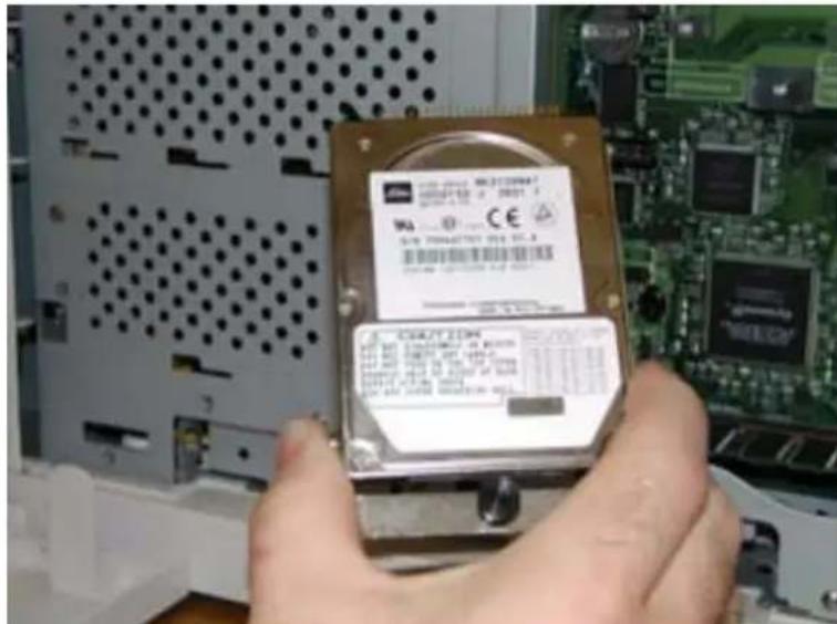
- Be sure to align the Hard Drive as depicted by the alignment drawing on the controller, making sure that the two top pins to the left of the connector are free standing and not connected.

8-8 34PPM Laser Printer User Guide
Installing the Hard Disk Option in the Printer
- If there is improper alignment, remove the Hard Drive and reinstall.
NOTE: Improper alignment will damage the hard drive and possibly the controller board.
- Insert the plastic rivet through the aligned hole.

natural_image
Interior view of a computer hard drive module showing internal circuit board and hard drive casing (no readable text or symbols)-
Reinstall the side covers in reverse order of steps 3, 4, and 5. Once firmly in place, push and hand tighten the thumbscrews in a clockwise direction.
-
Connect the power cord to the wall outlet. Turn the printer power switch to the ON position.
The installation of your Hard Disk option in your printer is now complete.
Using the Hard Disk Option and User Flash DIMM Module
This section discusses the available control panel menus when the Hard Disk or User Flash option is installed. Power-on files and the storage of files on the Hard Disk and User Flash option are also discussed.
Operator Panel MENU Structure
When the Hard Disk or User Flash option is installed, the printer control panel menu structure is enhanced as shown in the following table. The shaded areas denote additional features and settings relevant to the Hard Disk or User Flash option.
| Menu | ||||
| Job Library | ||||
| Job Accounting | ||||
| Paper Menu | ||||
| Interface Menu | ||||
| PS Menu | ||||
| PCL Menu | ||||
| System Menu | ||||
| Display Language | ||||
| Alarm Control | ||||
| Power Saver | ||||
| Wait Timeout | ||||
| Job Timeout | ||||
| Jam Recovery | ||||
| Hex Print | ||||
| Intellifilter | ||||
| Power-On Files | ||||
| Playback FILE01.POR | ||||
| FILE02.POR | ||||
| FILE03.POR | ||||
| ... | ||||
| ... | ||||
| Delete FILE01.POR | ||||
| FILE02.POR | ||||
| FILE03.POR | ||||
| ... | ||||
| ... | ||||
| Quality Menu | ||||
| Functions | ||||
| Disk Menu | ||||
| Delete | ||||
| Format Disk | ||||
| Disk Summary | ||||
| Flash Menu | ||||
| Delete | ||||
| Format Disk | ||||
| Disk Summary | ||||
NOTE: 1. The Flash Menu and Disk Menu will only appear when the respective FLASH SIMM and/or Hard Disk option is installed.
2. Power-On Files menu will only appear if either a FLASH SIMM or a Hard Disk option is installed and power-on files exist.
Using the Disk Menu
Manipulation of files stored on the hard disk option can be accomplished using the Disk Menu.
| Disk Menu | |
| Delete | |
| Format Disk | |
| Disk Summary |
This selection will read the selected file from the Hard Disk and print it as if it were being received from one of the input ports.
Delete
This selection will delete the selected disk file or directory from the hard drive. To delete an entire directory, you must first delete all the files within that directory.
Format Disk
This selection will reformat the hard drive. All files on the hard drive will be deleted if this function is selected.
Disk Summary
This selection will print a page containing information about the hard disk drive including a list of all the current existing files and directories.
Using the Flash Menu
Manipulation of files stored in the FLASH SIMM can be accomplished using the Flash Menu.
| Flash Menu | |
| Delete | |
| Format Disk | |
| Disk Summary |
This selection will read the selected file from the FLASH SIMM and print it as if it were being received from one of the input ports.
Delete
This selection will delete the selected file or directory from the FLASH SIMM. To delete an entire directory, you must first delete all the files within that directory.
Format Flash
This selection will reformat the FLASH SIMM. All files on the FLASH SIMM will be deleted if this function is selected.
Flash Summary
This selection will print a page containing information about the FLASH SIMM including a list of all the current existing files and directories.
Using the FLASH SIMM or Hard Disk Option as a PostScript Device
In order to allow PostScript programs to access the FLASH SIMM and/or hard disk options, a full implementation of a PostScript storage device is provided. This section discusses an overview of the PostScript operators and parameter sets that are included in the support.
For detailed information on using the operators/parameter sets, please refer to the following publications:
PostScript Language Reference Manual
Adobe PostScript 3 Version 3010 Product Supplement
Device Names and Priority
The device names assigned to the FLASH SIMM and hard disk options are as follows:
%flash% device name for the FLASH SIMM
%disk0% device name for the hard disk
If both devices are installed, both devices can be referenced uniquely by name. If no device name is specified in the PostScript operation, the SearchOrder parameter in the device parameter set establishes the priority for file operations. When both devices are installed, the SearchOrder value for the hard disk is set to 1, while the SearchOrder value for the FLASH SIMM is set to 2. This gives priority to the hard disk.
PostScript Operators
All of the standard file-object related operators (file, read, write, etc.) are supported. In addition, following is a list of device-related PostScript Compatibility operators that are supported for use with the FLASH SIMM(%flash%) or hard disk (%disk0%) options:
- devdismount
- devforall
- devformat
- devmount
- devstatus
- diskonline
- diskstatus
- initializedisk
- dosysstart
- setdosysstart
Device Parameter Sets
When installed, a device parameter set will be supported for either or both FLASH SIMM and hard disk options. The parameter sets can be referenced using the device names %flash% or %disk0%. Each parameter set will include the following parameters:
- LogicalSize
- Writeable
- BlockSize
- Searchable
- SearchOrder
- Type
- Mounted
- HasNames
- PhysicalSize
- InitializeAction
- Free
- Removable
Warmstart.ps and Sys/Start Files
When either or both the FLASH SIMM or hard disk options are installed, there are two features which provide support for automatic execution of a PostScript program during power-on initialization.
The first feature is the warmstart.ps file. Each time the printer is powered on, either or both optional storage devices will be checked for a file named warmstart.ps. If this file is found, it will be read and parsed by the PostScript interpreter. It is up to the PostScript programmer to create the content of this file and get the file onto the storage device using the PostScript device and file operators.
The second feature is the Sys/Start file. If either or both of the optional storage devices are installed, an additional parameter will be supported in the System Parameter set. This parameter is an integer parameter called StartupMode and is set to 1 by default.
NOTE: This parameter can be read or written using the dosysstart and setdosysstart operators.
Each time the printer is powered on, if the StartupMode parameter is set to 1, either or both the optional storage devices will be searched for a file called Sys/Start, a file named Start in a path called Sys. If this file is found, it will be read and parsed by the PostScript interpreter. Again, it is up to the PostScript programmer to create the content of this file and get the file onto the storage device using the PostScript device and file operators.
Using the Power-On Files Feature
Power-on Files Defined
If a FLASH DIMM or hard disk drive is installed in your printer, your printer has the capability of storing additional power-on files which can be read and interpreted at power-on. Power-on files are processed at power-on initialization only and not at the start of every print.
Power-on files can contain either PCL or PostScript language content. Examples of power-on files include soft fonts, and macro/overlay definitions. The FLASH DIMM can store approximately 8MB of file storage, the hard disk drive storage depends on the size of the drive that is installed in your printer.
Optional operator panel menu selections become available when either of these options are installed and power-on files are detected.
Collating, Saved Jobs, and Job Accounting
The features discussed in this section are designed to work with the Hard Disk Option. However, if no Hard Disk Option is installed, but a User Flash Option is installed, these features will utilize the User Flash Option. If both the Hard Disk Option and a User Flash Option are installed, these features will default to the Hard Disk Option.
There are two new features available using the Hard Disk or User Flash Option; Collating and Saved Jobs. The drivers that support these new features are as follows:
- PCL - All windows platforms
- PostScript – Windows 2000 and Windows XP
Collating Feature
When this feature is enabled, multiple copies of the entire document (all pages e.g. 1-3, 1-3, 1-3) will be printed in sequential order rather than multiple copies of each individual page (111, 222, 333).
You access the collating feature through the drivers that support this feature. But, before these features can be used, either Flash or Disk must be set as installed in driver Device Settings. To access the Collating feature on your desktop, go to the Start menu, left click on Settings, left click on Printers, and then click on your printer driver icon, right click and follow the menu to the Properties menu.
Use the following procedure to enable collating:
- Click on the Device Settings button. Scroll down and make sure a Hard Disk option or User Flash is installed. Then click the OK button. A Hard Disk or User Flash must be installed to use the Collating Feature.
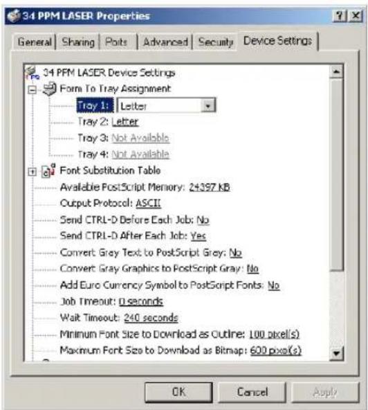
- Press the Printing Properties button printer icon.
- Click on the Printing Preferences button.

- Click on the Paper Quality button and then the Advanced button.

- Click on the Copy Count button to enter the number of copies and make sure the Collate button is checked.

- Click to OK button and your printer driver is set to collate the number of copies specified.
Saved Jobs Feature
You can create saved jobs using the drivers that support this feature. The drivers that support this feature are as follows:
- P C L - A l l w i n d o w s p l a t f o r m s
- PostScript – Windows 2000 and Windows XP
There are three job types available, Normal, Saved, and Private. The descriptions of the job types are as follows:
Normal
A normal print job. No print job data is saved.
Saved
The print job data is saved on the Hard Disk or User Flash Option. The job will be saved in the "Job Library" folder. A sub-folder in the Job Library folder will be created, if necessary, for the user, as specified by the user name. The print job will be stored in a file in this folder with a name created by the user in the job name field of the printer driver.
Private
The print job data is saved on the Hard Disk or User Flash Option. The job will be saved in the "Job Library" folder. A sub-folder will be created, or the by the user as specified by user name. The print job will be stored in a file in this folder, with a name specified by user in the job name field of the printer driver. "Private" print job files are secured by having an associated PIN which is entered in the PIN field of the driver by the user. Any access to this file will require the PIN to be entered.
To access the Saved Jobs on your desktop, go to the Start menu, left click on Settings, left click on Printers, and then click on your printer driver icon, right click and follow the menu to the Properties menu.
- You are now in the Printing Properties menu, click on the Printing Preference button.
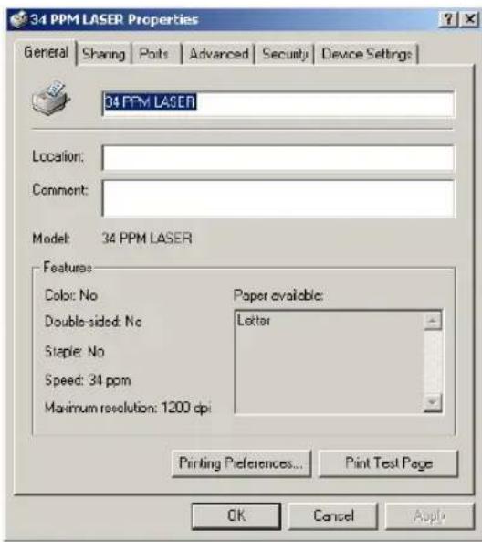
- Click on the Paper Quality button and then the Advanced button.

- Now scroll down to the Job Type Section of the menu.

- When you click on Job Type, three job types are available. Normal, Saved, and Private.
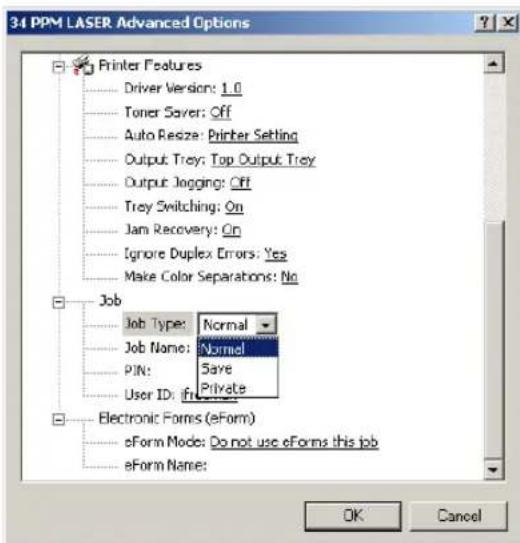
- If you want to Save your print job, enter a name you want to save the job as and it will be saved under User ID folder listed. You can change the User ID in this menu also.

- If you want to make your job Private, you can enter a number in the PIN menu. You will only be able to print this document if you know the PIN number.

Working with Saved Jobs
There are two ways to work with Saved Jobs. One is through the front panel menus, the other is through the printer web pages.
Front Panel Access
The Job Library Menu provides access to the printer settings that are related to the optional Hard Disk. Use the following procedure to enter the Job Library Menu to Print or Delete jobs that are Saved in the Job Library, including jobs that have a PIN number:
- Press the MENU button on the control panel.
- Press the NEXT button until the text "Job Library Menu" is shown on the second line of the display.
- Press the SELECT button to enter the Job Library Menu.
- Press the NEXT button to move through the submenus: Print or Delete.
- Press the SELECT button to enter a submenu.
Use the procedures in the following table to access and change the system settings.
| Menu Submenus | Procedure for Changing Setting | |
| Job Library(Saved Job) | Print(To print a saved job) | 1. Press NEXT or PREVIOUS to scroll through Print or Delete options.2. Press SELECT to choose Print. |
| PrintUser Folder 1 | 1. Press NEXT or PREVIOUS to scroll through the User Folder Names.2. Press SELECT to choose the desired User Folder. | |
| PrintJob1 | 1. Press NEXT or PREVIOUS to scroll through the Print Job Names.2. Press SELECT to choose the desired Print Job. | |
| Job NameCopies – Select 1-99 | 1. Press NEXT or PREVIOUS to increase or decrease each digit of the two-digit number.2. Press SELECT set one digit and move to the next digit.3. Press SELECT after changing the last digit to save this setting. | |
| Job NameCopies | 1. Press SELECT to print the job. | |
| PrintingPlayback | 1. The printer will display PRINTING on Line 1 and PLAYBACK on Line 2 of the display while printing the job. | |
| Job Library(Saved Job with PIN) | Print(To print a saved job with a PIN) | 1. Press NEXT or PREVIOUS to scroll through Print or Delete options.2. Press SELECT to choose Print. |
| PrintUser Folder 1 | 1. Press NEXT or PREVIOUS to scroll through the User Folder Names.2. Press SELECT to choose the desired User Folder. | |
| PrintJob1 | 1. Press NEXT or PREVIOUS to scroll through the Print Job Names.2. Press SELECT to choose the desired Print Job. | |
| Job NamePIN | 1. Press NEXT or PREVIOUS to increase or decrease each digit of the four-digit number.2. Press SELECT to set one digit and move to the next digit.3. Press SELECT after changing the last digit to save this setting. | |
| Job NameINCORRECT PIN | 1. If an incorrect PIN is entered, press PREVIOUS to re-enter the correct PIN. | |
| Job NameCopies – Select 1-99 | 1. Press NEXT or PREVIOUS to increase or decrease each digit of the two-digit number.2. Press SELECT to set one digit and move to the next digit.3. Press SELECT after changing the last digit to save this setting. | |
| Job NameCopies | 1. Press SELECT to print the job. | |
| PrintingPlayback | The printer will display PRINTING on Line 1 and PLAYBACK on Line 2 of the display while printing the job. | |
| Job LibraryDELETE | Delete(To delete a saved job) | 1. Press NEXT or PREVIOUS to scroll through Print or Delete options.2. Press SELECT to choose Delete. |
| DeleteUser Folder 1 | 1. Press NEXT or PREVIOUS to scroll through the User Folder Names.2. Press SELECT to choose the desired User Folder. | |
| DeleteJob1 | 1. Press NEXT or PREVIOUS to scroll through the Print Job Names.2. Press SELECT to choose the desired Print Job to Delete. | |
| Job Library(Delete SavedJob with PIN) | Delete(To delete a saved job with a PIN) | 1. Press NEXT or PREVIOUS to scroll through Print or Delete options.2. Press SELECT to choose Delete. |
| DeleteUser Folder 1 | 1. Press NEXT or PREVIOUS to scroll through the User Folder Names.2. Press SELECT to choose the desired User Folder. | |
| DeleteJob1 | 1. Press NEXT or PREVIOUS to scroll through the Print Job Names.2. Press SELECT to choose the desired Print Job to Delete. | |
| Job NamePIN | 1. Press NEXT or PREVIOUS to increase or decrease each digit of the four-digit number.2. Press SELECT to set one digit and move to the next digit.3. Press SELECT after changing the last digit to save this setting. | |
| Job NameINCORRECT PIN | 1. If an incorrect PIN is entered, press PREVIOUS to re-enter the correct PIN. | |
| Job Name 1. Press SELECT to Delete the job. | ||
Job Accounting Feature
The printer supports a job accounting feature which will store certain information about each print job received by the printer. There are two ways to work with this feature. One is through the front panel menu.
NOTE: Please see "Accessing the Printer Web Page" on page 8-30 for more information on the Job Accounting Feature.
Front Panel Access
The Job Accounting Menu provides access to functions and settings related to this feature. Use the following procedure to enter the Job Accounting Menu to change the settings or access the functions:
- Press the MENU button on the control panel.
- Press the NEXT button until the text "Job Accounting Menu" is shown on the second line of the display.
- Press the SELECT button to enter the Job Accounting Menu.
- Press the NEXT button to move through the submenus: Enable, Print Info, Reset Info.
- Press the SELECT button to enter a submenu.
Use the procedures in the following table to access and change the system settings.
| SubMenu Settings | Procedure for Changing Setting | |
| ENABLED Yes | or No 1. Press NEXT or PREVIOUS to scroll through Yes orNo options.2. Press SELECT to choose Yes to turn on this function. | |
| PRINT INFO 1. | Press SELECT to begin printing the Job AccountingSummary Report. | |
| RESET INFO 1. | Press SELECT to reset the Job AccountingInformation. This will delete all stored information related to jobs received by the printer. |
When you print a Job Accounting Summary the following information will print on your report:
| Job Name | User Name | Port | Protocol | Pages (sides) | Pages (sheets) | Date/Time | Duration |
| job2 | jerry | parallel | 4 | 4 | March 30 2004 01:11:10 PM | 00:00:08 | |
| job1 | jerry | network1 | LPD | 4 | 4 | March 30 2004 01:12:10 PM | 00:00:04 |
NOTE: Only products that have real time clock support will provide the Date/Time information.
Using the Custom Paper Size Feature
There are two ways to work with the Custom Paper Size Feature. One is through the front panel menus, the other is through the printer driver. If you have a Windows or Macintosh printer driver, you can access this feature from the driver and you do not have to use front panel settings. Use the front panel access to these features if you have a Unix system or do not have Windows or Macintosh drivers.
Operator Panel Access
The Paper Menu provides access to the Custom Paper Size settings. The range for setting a custom paper size is:
Paper Width 3.5 inches minimum to 8.5 inches maximum
Paper Length 5.5 inches minimum to 35.43 inches maximum
Use the following procedure to enter the Paper Menu to set a Custom Paper Size:
- Press the MENU button on the control panel.
- Press the NEXT button until the text "Paper Menu" is shown on the second line of the display.
- Press the SELECT button to enter the Paper Menu.
- Press the NEXT button until the text "Media Size/Type is shown on the second line of the display and press the SELECT button.
-
Press the NEXT button until the text "MBF" is shown on the second line of the display.
-
Press the SELECT button.
-
Press the NEXT button until the text "Custom Size" is shown on the second line of the display.
-
Press the SELECT button to enter the "Custom Size" menu. "Width" is shown on the second line of the display.
-
Press NEXT or PREVIOUS to increase or decrease each digit of the three-digit number to set the width of your paper. When the width of paper is correct, press the SELECT button.
-
Next "Length" is shown on the second line of the display.
-
Press NEXT or PREVIOUS to increase or decrease each digit of the three-digit number to set the length of your paper. When the length of paper is correct, press the SELECT button.
-
Press RETURN until you exit out of all the submenus and return to READY.
Printer Driver Access
To access the Custom Paper Size Feature through your printer driver, use the following procedure:
-
On your desktop, go to the Start menu, left click on Settings, left click on Printers, and then click on your printer driver icon, right click and follow the menu to the Properties menu.
-
You are now in the Printing Properties menu, click on the Printing Preference button.

- Click on the Paper Quality button and then the Advanced button.

- Click on the Paper Size button.
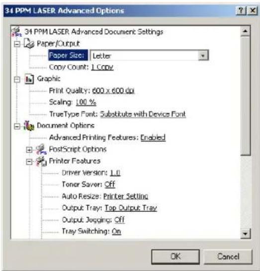
- Scroll down and click on PS Custom Page Size.

- Then enter the width and height of your custom paper size.
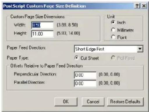
- Click the OK button until you exit out of the driver menu. You are now ready to print your custom sized document.
Custom Page size and Microsoft Word, Word 2000, and Word 2003
When you specify a PostScript custom page size in the Paper Size box in the advanced printer properties for a supported printer, the custom size setting appears to be ignored if you have configured Microsoft Word to use the PostScript Custom Page Size setting. Word defaults to the default size of 8.5 by 11 inches. Word is limited to a maximum length of 22 inches.
Resolution
If you want to use PostScript custom page sizes that are supported by a printer, the only way to make them work correctly in Word is to add custom forms to Windows and then to choose those form names in Word. By using this method, the PostScript Page Size setting in Word is ignored, and the newly added forms are used instead.
Create a custom form for printing to a non-standard paper size in Microsoft Windows NT 4.0, Windows 2000, and Windows XP.
To create a custom form, follow these steps:
- Navigate to CONTROL PANEL, double click PRINTERS.
■ On the FILE menu, click SERVER PROPERTIES.
■ On the FORMS tab, select the CREATE A NEW FORM check box.
Enter the settings for the new form.
NOTE: When you set up a custom form, the margins cannot go beyond the confines of the specifications for the installed printer driver. Printable regions must be adhered to with regard to margin limits for the printer and driver in use.
- Click SAVE FORM or OK
To use the new form as the default form, follow these steps:
WINDOWS NT
In CONTROL PANEL, double-click PRINTERS.
■ Right-click the printer you want to select, and then click DOCUMENT DEFAULTS.
■ In the PAPER SIZE box, click the new form.
- Click OK.
WINDOWS 2000 AND XP
■ In CONTROL PANEL, double-click PRINTERS.
■ Right-click the printer you want to select and then click PROPERTIES.
■ On the GENERAL tab, click PREFERENCES.
- On the PAPER QUALITY tab, click ADVANCED, and then in the PAPER SIZE drop down menu, select the custom form size.
- Click OK.
To use the new form from a program, follow these steps:
■ In the program, click PRINT.
■ In the PRINT dialog box, click PROPERTIES.
■ In the PAPER SIZE box, click the new form.
- Click OK.
- Click OK to print.
NOTE: New forms are stored on the computer where they are created. When you create a new form for use with a shared printer, create the form on the print server.
NOTE: On a Windows 2000 and XP computer, occasionally the newly created form will not appear in the drop down list under paper size. If you encounter this, you may need to select an existing form under server properties, modify the settings, check box to create a new form, change the form name and save the form. Once you save the form, it should appear in the paper size drop down box.
Accessing the Printer Web Page
You can access the printer web page by going to the internet browser and typing the IP address of your network printer (http://IP ADDRESS). You can directly access the printer control panel on the web and it allows you to view and change the printer settings. Following is an example of the printer web page:

When you access the printer web page it will display your printer name and logo and provide access to the following menus:
| Main Page of Printer Web Site Submenu 1 of Printer Web Site Submenu 2 of Printer Web Site | ||
| Printer SetupYou can view and change printer configuration. With access to the following menus: | Paper MenuProvides access to the printer settings for various paper-handling functions: | CopiesDuplexDuplex BindDefault SourceManual FeedOutput TrayMedia Size/TypeTray LinkingJob OffsetBlank PagesFace Up InstMBF FirstGloss LevelAuto ResizeSeparator PageCustom Size Unit |
| Interface MenuProvides access to the printer interface settings: | PortParallelNetwork 1USBParallel SetupInterpreterFormatModeDelay Out CloseNetwork 1SetupInterpreterFormatNetwork AddressIP AddressSubnet MaskDefault RouterLPD BannerDHCPDelay Out CloseHost NamemDNSLocal LinkmDNS Host NamentDNS Svc NameMulti-SessionAppleTalkCurrent ZonePreferred ZoneBinary PSFactory DefaultsConnection SpeedUSB SetupInterpreterFormatDelay Out CloseBinary PS | |
| PS MenuProvides access to the PostScript settings: | Print PS ErrorsManual Feed TO | |
| PCL MenuProvides access to the PCL settings: | OrientationFont SourceFont NumberPitchSymbol SetMacro FilterLines Per PageCR ModeLF ModeFF ModePrint AreaParameter ValuesPaper SourcePaper Size | |
| System MenuProvides access to the system settings: | Factory DefaultsDisplay LanguageAlarm ControlPower SaverWait TimeoutJob TimeoutJam RecoveryHex PrintIntellifilter | |
| Quality MenuProvides access to the printer settings that are related to print quality: | ResolutionToner Saver | |
| Color MenuContains the settings related to the quality of printed color: | Screening ModeRendering IntentColor MatchingAlignment | |
| Email SetupProvides access to the following settings which allow the administrator to set parameters for specific conditions and have an email alert sent to specific addresses. | Email Server Settings:SMTP Server IP AddressEnable AuthenticationUser Name: (for Authentication)Password: (for Authentication)Printer Email AddressReply-To-AddressEmail Address Settings:Example:jsmith@abc_co.comEmail Alert Conditions:Re-send IntervalOff LineConsumablesToner Low/Toner OutPaper Low/Paper OutPaper JamCover OpenStacker ErrorMass Storage ErrorRecoverable ErrorService Call RequiredEmail Signature Settings | |
| Printer StatusDisplays printer option and consumables status. You can view the current settings for the Input options on your printer and the Output options installed. | ||
| Input Displays paper trays and the | paper size, type and capacity levels of all installed trays and options. | |
| Output Displays output paper trays and capacity level. | ||
| Consumable Information Displays | all four toner cartridges and percentage used. Also displays the Color Page Count, BTR Pages, Fuser Pages, and Drum Time. | |
| Other Sheet Counter | Image Counter | |
| AdministrationDisplays security and factory defaults. Allows you to set up support and supplies web links. | ||
| Factory Defaults | ||
| Console Security | ||
| Refresh Rate | ||
| Support Link | ||
| Main Page of Printer Web Site | Submenu 1 of Printer Web Site | Submenu 2 of Printer Web Site |
| Supplies Link | ||
| File ManagementAllows you to access (print or delete) files stored on your Hard Disk or User Flash. | ||
| Only appears if User Flash is installed. | User Flash Files You can view contents of folder, retrieve files or delete print files. | |
| Format User Flash Allows you to format your User Flash. | ||
| Print User Flash Summary Prints a summary page of the files stored in the User Flash. | ||
| Only appears if Hard Disk Option is Installed. | Hard Disk Files You can view contents of folder, retrieve files or delete print files. | |
| Format Hard Disk Allows you to format your Hard Disk. | ||
| Print Disk Summary Prints a summary page of the files stored on the Hard Disk. | ||
| Job AccountingView, retrieve, or reset job accounting information. | ||
| Enable/Disable Click Yes or No to Enable or Disable Job Accounting | ||
| Retrieve Job Accounting File Retrieve a job file and upload the file information to a CSV file. | ||
| Display Job Accounting Info Displays all job information such as job name, user name, port, protocol, pages, date/time and duration. | ||
| Reset All Job Accounting Info Deletes all stored Job Accounting information. | ||
| Product SupportDirect link to obtain technical support | Takes you to the Product Support Website where you can obtain technical support. | |
| Product SuppliesDirect link to order supplies | Takes you to the Product Supplies Website where you can order product supplies. | |
| Main Page of Printer Web Site Submenu 1 of Printer Web Site Submenu 2 of Printer Web Site | ||
| Fonts and MacrosAllows you to view the PostScript Fonts and PCL Fonts, stored internally on your printer. Also allows you to view Macros stored on your Hard Disk or User Flash Options. | PS FontsPCL FontsMacros | |
| Job LibraryTakes you to the job library where you can view all user folders and print jobs. Also allows access to print or delete all files stored in your job library on your Hard Disk or User Flash Option. Allows you to save private jobs with a PIN. | View contents of user folder.Retrieve files.Delete or print selected files. | |
Printer Setup
Go to your web browser and type in your printer web address. The printer web page will appear.
1. Click on Printer Setup

- When you enter the Printer Setup Menu, you have access to the Paper Menu, Interface Menu, PS Menu, PCL Menu, System Menu, Quality Menu and Email Setup.

- The Paper Menu allows the user to access and change the paper menu settings.

- The Interface Menu allows the user to access and change the interface settings.

- The PS Menu allows the user to access and change the Post Script Menu settings
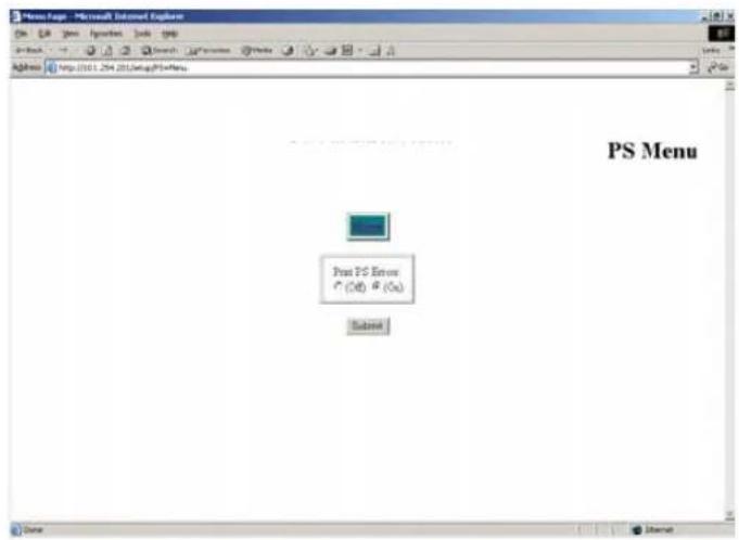
- The PCL Menu allows the user to access and change the PCL settings

- The System Menu allows the user to access and change the System Menu settings

- The Quality Menu allows the user to access and change the Quality Menu settings

- The Date/Time Menu allows the user to access and change the Date.

- The Email Setup Menu allows you to configure the printer to send email messages when certain status conditions occur.

Email Server Settings
-
SMTP Server IP Address : Enter the IP address for the SMTP server that the printer will use to transmit the email messages.
-
Enable Authentication: Check this box if the SMTP server requires authentication.
-
Uscr Name: (for Authentication) Enter the name of a user who is authorized to access the SMTP server.
-
Password: (for Authentication) Enter the password for the user who is authorized to access the SMTP server.
-
Printer Email Address: The character string configured here will be used in the "FROM" field of the email message.
-
Reply-To-Address: The character string configured here will be used in the "REPLY TO" field of the email message.

Email Address Settings/Email Alert Conditions
You can configure 1 – 5 destination email addresses. For each of these destination email addresses you can configure which status conditions will cause an email to be sent. In addition, a resend interval can be set for each address, which determines if or how often the email message should be resent, as long as the condition persists.
Email Signature Settings
These are text strings that are appended to the end of the email messages. They can be used to provide helpful hints/reminders to recipients of the status email messages.
Job Accounting
Web Page Access
Go to your web browser and type in your printer web address. The printer web page will appear.
- Click on Job Accounting.
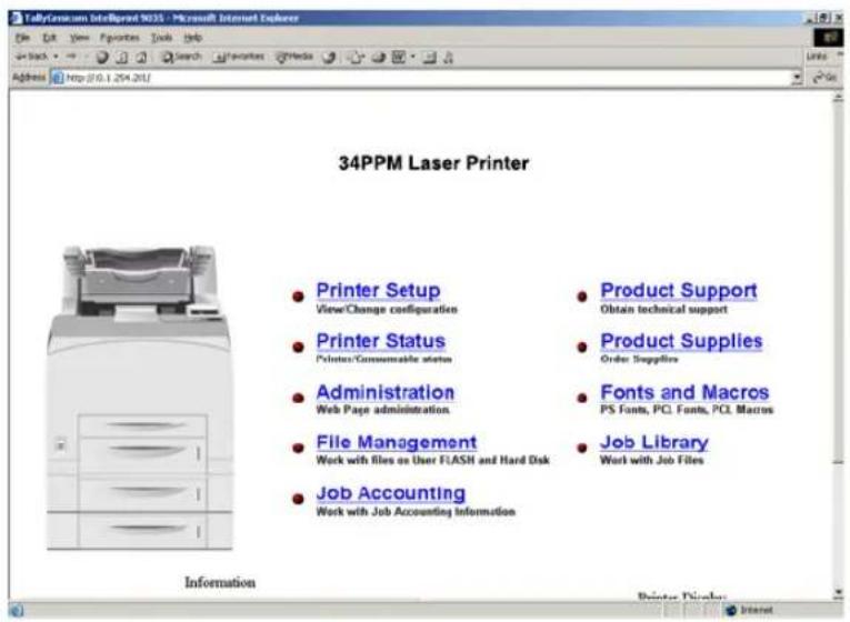
- When you enter the Job Accounting field the following options appear:
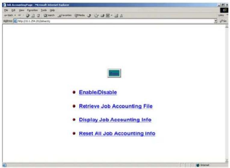
- When you click on Enable/Disable it will take you to the following screen. Click Yes or No to Enable or Disable Job Accounting.
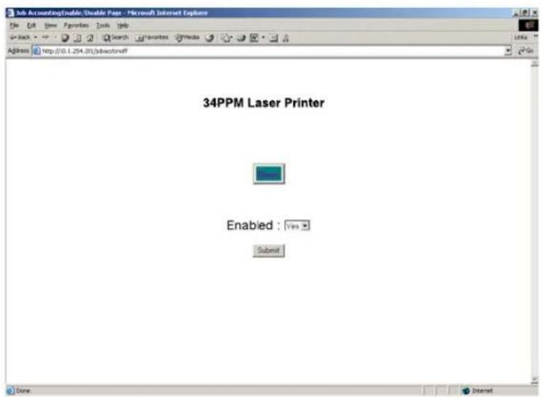
- When you click on Retrieve Accounting Files it will upload the file information, which is stored in a .CSV file.

- When you click on Display Job Accounting Info it will bring you the following screen which displays all your job information.
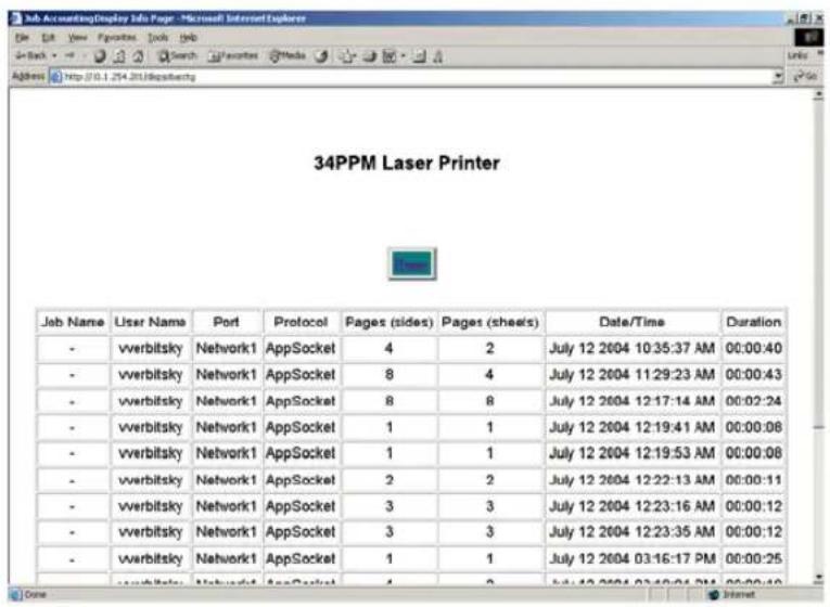
NOTE: Only products that have real time clock support will provide the Date/Time information.
- When you click on Reset All Job Accounting Info, all printer job information will be deleted.
File Management
Web Page Access
Using the printer web page, you can delete, print, or download any job files stored in the job library. Go to your web browser and type in your printer web address. The printer web page will appear as follows:
1. Click on Job Library.

2. Click on the folder icon or name to view the printer jobs in the user folders.

- The printer job information will appear. If there is a PIN number associated with the file, you will be required to enter the correct PIN number to access the print file.
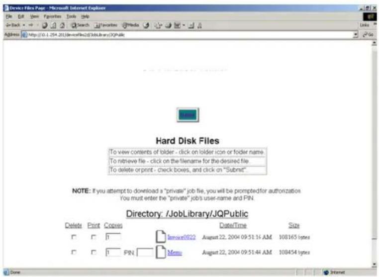
Appendix A
Consumables
In this Chapter . . .
■ "Specifications" on page A-2
■ "Expected life of Consumables" on page A-3
Specifications
| Machine type Desktop | ||
| Printing system Laser xerography | ||
| Printing speed 34 sheets/minute (for continuous printing of the same A4-sized document by short edge feed) | ||
| Warm-up time Maximum of 17 seconds from power on at 22°C | ||
| Resolution 1200 dots/25.4 mm and 600 dots/25.4 mm | ||
| Paper feed Auto | ||
| Paper size A4, 1/3 A4, B5 JIS, B5 ISO, 8.5 × 11" (Letter), 8.5 × 13"(Legal 13), 8.5 × 14" (Legal 14), 7.5 × 11.5" (Executive), 5.5 × 8.5" (Statement) | ||
| Paper type Plain, Thick1, Thick2 paper (60-216 g/m2), transparencies, envelopes*, labels* *some envelopes and labels cannot be used due to the paper quality and size | ||
| Paper supply(standard paper) | Paper tray(standard paper) | Paper tray (A4/150 sheets): 150 sheetsPaper tray (A4/550 sheets): 550 sheets |
| Paper tray(optional) | Paper tray (A4/550 sheets): 550 sheets | |
| Output tray capacity 500 sheets (64 g/m | 2) | |
| Operating noise 53.6 db(A) or less during operation, 27 db(A) or less during standby mode | ||
| Power 100 V ± 10%, 50/60 Hz ± 3 Hz | 220 V ± 10%, 50/60 Hz ± 3 Hz | |
| Maximum power consumption 995 W or less during operation13 W or less during standby mode | ||
| Dimensions 422 (W) × 465 (D) × 404 (H) mm*before installing paper tray and when paper tray is contracted | ||
| Weight 21.0 kg* | *before installing paper tray | |
Printable area

Expected life of Consumables
Toner Cartridge
| Type of Toner Cartridge Possible number of pages printed | |
| 17 Kpv About 17,000 sheets | |
The possible number of pages that can be printed is based on Letter size paper with a print ratio of 5% and the default density setting. The number of pages that actually can be printed varies according to the conditions of use.
| Paper size Letter size | |
| Paper feeding direction Long edge feed | |
| Paper Standard paper | |
| Print ratio 5% | |
| Print density Default setting values |
Fuser unit, transfer roll cartridge and feed roll
| Regular replacement parts Possible | number of pages printed |
| Fuser unit About 200,000 sheets | |
| Transfer roll cartridge | |
| Feed roll |
The possible number of pages that can be printed is based on Letter size paper with a print ratio of 5% and the default density setting. The number of pages that actually can be printed varies according to the conditions of use.
TALLYGENICOM REPRESENTATIVES
GERMANY
TallyGenicom
Joaquin Lorenzo 4, Local
28033 Madrid
España
Phone: +34 902 196 183
Fax: +34 913 739 943
http://www.tallygenicom.es
SINGAPORE
TallyGenicom Pte. Ltd
63 Hillview Avenue
08-22, Lam Soon Industrial Building
Singapore 669569
Phone: +65 6760 8833
Fax: +65 6760 1066
http://www.tallygenicom.com.sg
U.S.A.
TallyGenicom
4500 Daly Drive, Suite 100
Chantilly, VA 20151
U.S.A.
TallyGenicom Limited
Rutherford Road
Basingstoke, Hampshire
RG24 8PD
England, U.K.
Phone: +44 870 872 2888
Fax: +44 870 872 2889
http://www.tallygenicom.co.uk
CANADA
TallyGenicom
125 Traders Boulevard, 9
Missisauga, Ontario L4Z 2E5
Canada
TallyGenicom Sdn. Bhd.
Wisma KT, Suite 3.02
No 14 Jalan 19/1
46300 Petaling Jaya
Selangor Darul Ehsan
Malaysia
Phone: +3 7625 1988
Fax: +3 7625 2688
http://www.tallygenicom.com.my
FRANCE
TallyGenicom S.A.
19 avenue de L'Ile Saint Martin
F-92237 Nanterre Cedex
France
Tél.: +33 1 41 30 11 00
Fax: +33 1 41 30 11 10
http://www.tallygenicom.fr
AUSTRIA
TallyGenicom Ges.m.b.H.
Eduard-Kittenberger-Gasse 95B
A-1232 Wien
Austria
Tel.: +43 1 863 40 0
Fax: +43 1 863 40 240
http://www.tallygenicom.co.at
Russian Federation and C.I.S.
TallyGenicom Representative
Park Place Moscow
Office D-206
Leninsky Prospekt 113/1
117198 Moscow
Russian Federation
Phone: +7 095 956 56 40
Fax: +7 095 956 55 41
http://www.tallygenicom.ru
- TallyGenicom Intelliprint
- 9035
- Laser Printer
- Trademarks
- Copyright Notice
- Contents
- Preface 0-1
- Chapter 1 Installing the Printer 1-1
- Chapter 2 Daily Care 2-1
- Chapter 3 Troubleshooting 3-1
- Chapter 4 Clearing Paper Jams 4-1
- Chapter 5 About Consumables 5-1
- Transfer Roll Cartridge 5-11
- Feed Roll 5-15
- Chapter 6 Optional Accessories 6-1
- Available Optional Accessories 6-2
- Tray module (A4/550 sheets) 6-2
- Paper trays 6-13
- Offset catch tray 6-17
- Rear tray 6-23
- Chapter 7 Understanding and Navigating the Control Panel Menus 7-1
- About this Chapter 7-2
- Control Panel Features 7-2
- Navigating the Control Panel Menus 7-4
- Menu Structure 7-6
- Job Library 7-7
- Chapter 8 Optional Extended Features 8-1
- Appendix A Consumables A-1
- Preface
- In this Chapter ...
- Welcome
- About this Manual
- Scope
- Overview
- Printer Orientation
- Conventions
- Organization
- Safety Notes
- Chapter 1 Installing the Printer
- Chapter 2 Daily Care
- Chapter 3 Troubleshooting
- Chapter 4 Paper Jams
- Chapter 5 Consumables
- Chapter 6 Optional Accessories
- Chapter 7 Navigating the Control Panel Menus
- Chapter 8 Optional Extended Features
- Appendix A
- Special Features of This Printer
- Chapter 1
- Installing the Printer
- In this Chapter . . .
- About this Chapter
- Installation Location
- Installation Environment
- Using a power outlet exclusively for the printer
- Unsuitable locations
- When using an ultrasonic humidifier
- Safety Precautions
- Handling the Printer
- Printer Location Requirements
- Printer Weight and Dimensions
- Installation Space
- Checking the Package Contents
- Carrying the Printer
- Installation Procedure
- Removing the Tape
- Installing the Optional Accessories
- Installing the Toner Cartridge
- Loading Paper
- Loading paper larger than A4 size in the paper tray
- Connecting the Power Cord
- Turning the Printer On
- Selecting a Display Language
- Installing Printer Drivers and Locating User Documentation
- Installing Printer Drivers and other Software for UNIX and WindowsDrivers Folder
- TGNET Admin Administration Program
- Locating User Documentation
- Printing a Configuration Summary
- MENUS
- Paper Menu
- Media Size/Type
- Interface Menu
- Parallel Setup
- Network 1 Setup
- Network 1 Setup cont'd
- USB Setup
- PS Menu
- PCL Menu
- Parameter Values
- Paper Source
- Paper Size
- System Menu
- System Menu cont'd
- Quality Menu
- Date/Time Menu
- STATUS
- Tray 1
- Tray 2
- Tray 3
- Face Down Tray = OK
- INFORMATION
- OPTIONS
- Printing PCL and PostScript Font Lists
- Turning the Printer Off
- Chapter 2
- Daily Care
- Main Components and Their Function
- Front view
- Control panel
- Back view
- About Paper
- Usable Paper
- Standard paper
- Special media
- Loadable paper and capacity
- Available paper sizes
- Paper for 2 sided printing
- Unusable Paper
- Storing Paper
- Storing locations for paper
- Caution for storing paper
- Loading Paper in Paper Tray
- Loading Transparencies in the Paper Tray
- Cleaning the Printer
- Cleaning the exterior
- Cleaning the interior
- Cleaning the feed roll
- When Not in Use for a Long Time
- When Moving the Printer
- Chapter 3
- Troubleshooting
- When Problems Occur
- No Power
- Cannot Print
- Poor Print Quality
- Printout Is Faded, Stained, Missing, Wrinkled, or Blurred
- Other Problems
- Warning Messages and Error Messages
- Warning Messages
- Error Messages
- Chapter 4
- Clearing Paper Jams
- At the Paper Trays
- Pull the paper tray out of the printer.
- Remove any wrinkled paper in the paper tray.
- At the Fuser Unit
- At the Toner Cartridge
- At the Duplex Module
- At the paper exit
- At the interior of the top cover
- At the Offset Catch Tray
- Chapter 5
- About Consumables
- Available Consumables
- Toner Cartridge
- Regular replacement parts
- Cautions on Handling the Toner Cartridge
- Replacing the Toner Cartridge
- Fuser Unit
- Caution on Handling the Fuser Unit
- Replacing the Fuser Unit
- Transfer Roll Cartridge
- Caution on Handling the Transfer Roll Cartridge
- Replacing the Transfer Roll Cartridge
- Feed Roll
- Caution on Handling the Feed Roll
- Replacing the Feed Roll
- Feed roll at the paper tray
- Chapter 6
- Optional Accessories
- Available Optional Accessories
- Tray module (A4/550 sheets)
- Installing/Uninstalling the Tray Module
- Checking the contents of the tray module package
- Installing the Tray Module
- Uninstalling the Tray Module
- Paper trays
- Paper tray (A4/550 sheets)
- Duplex module
- Installing/Uninstalling the Duplex Module
- Installing the Duplex Module
- Uninstalling the Duplex Module
- Offset catch tray
- Installing/Uninstalling the Offset Catch Tray
- Installing the Offset Catch Tray
- Uninstalling the Offset Catch Tray
- Rear tray
- Installing/Uninstalling the Rear Tray
- Installing the Rear Tray
- Uninstalling the Rear Tray
- Chapter 7
- Understanding and Navigating the Control Panel Menus
- Control Panel Features
- LCD Display
- LED Indicators
- Pushbuttons
- Navigating the Control Panel Menus
- Menu Paper Menu
- Menu Structure
- Status Menu
- Job Library
- Job Library Errors
- JOBLIB Error XX
- Job Accounting
- Functions Menu
- FLASH Menu
- DISK Menu
- Chapter 8
- Optional Extended Features
- Installing DRAM Memory DIMMS
- Installing the Hard Disk Option in the Printer
- 8-8 34PPM Laser Printer User Guide
- Using the Hard Disk Option and User Flash DIMM Module
- Operator Panel MENU Structure
- Using the Disk Menu
- Delete
- Format Disk
- Disk Summary
- Using the Flash Menu
- Format Flash
- Flash Summary
- Using the FLASH SIMM or Hard Disk Option as a PostScript Device
- Device Names and Priority
- PostScript Operators
- Device Parameter Sets
- Warmstart.ps and Sys/Start Files
- Using the Power-On Files Feature
- Power-on Files Defined
- Collating, Saved Jobs, and Job Accounting
- Collating Feature
- Saved Jobs Feature
- Normal
- Saved
- Private
- Working with Saved Jobs
- Front Panel Access
- Job Accounting Feature
- Using the Custom Paper Size Feature
- Operator Panel Access
- Printer Driver Access
- Custom Page size and Microsoft Word, Word 2000, and Word 2003
- Resolution
- WINDOWS NT
- WINDOWS 2000 AND XP
- Accessing the Printer Web Page
- Printer Setup
- Click on Printer Setup
- (Off) # (On)
- (Off) # (Yes)
- (Off) # (No)
- Email Server Settings
- Email Address Settings/Email Alert Conditions
- Email Signature Settings
- File Management
- Web Page Access
- Click on Job Library.
- Click on the folder icon or name to view the printer jobs in the user folders.
- Consumables
- Printable area
- Expected life of Consumables
- TALLYGENICOM REPRESENTATIVES
- GERMANY
- SINGAPORE
- 08-22, Lam Soon Industrial Building
- U.S.A.
- CANADA
- FRANCE
- AUSTRIA
- Russian Federation and C.I.S.
Brand : TALLYGENICOM
Model : Intelliprint 9035
Category : Printer