
Intelliprint mL260 - Printer TALLYGENICOM - Free user manual and instructions
Find the device manual for free Intelliprint mL260 TALLYGENICOM in PDF.


| Type de produit | Line Matrix Printer |
| Print Technology | Impact Dot Matrix |
| Print Speed | Up to 500 lines per minute (LPM) |
| Print Resolution | 240 x 144 dpi |
| Form Width | Up to 16 inches (406 mm) |
| Copies Capacity | Original + 5 copies (6-part forms) |
| Paper Handling | Continuous forms, tear-off, push/pull tractors |
| Interfaces | Parallel (Centronics) and Serial (RS-232) |
| Emulations | IBM Proprinter, Epson FX, Printronix P-Series |
| Dimensions (L x W x H) | 20.1 x 9.8 x 7.9 inches (510 x 250 x 200 mm) |
| Weight | Approximately 40 lbs (18 kg) |
| Power Requirements | AC 100-240 V, 50/60 Hz, 2 A |
| Power Consumption | Operational: 150 W, Standby: 30 W |
| Noise Level | Operational: 55 dB(A) |
| Maintenance | Regular cleaning of print head and platen; replace ribbon cassette as needed |
| Safety Certifications | FCC Class A, UL, CSA, CE |
| Spare Parts & Repairability | Ribbon cassettes, print heads, logic boards, power supply; field replaceable units |
| General Information | Designed for high-volume printing of multi-part forms and labels |
Frequently Asked Questions - Intelliprint mL260 TALLYGENICOM
User questions about Intelliprint mL260 TALLYGENICOM
0 question about this device. Answer the ones you know or ask your own.
Ask a new question about this device
Download the instructions for your Printer in PDF format for free! Find your manual Intelliprint mL260 - TALLYGENICOM and take your electronic device back in hand. On this page are published all the documents necessary for the use of your device. Intelliprint mL260 by TALLYGENICOM.
USER MANUAL Intelliprint mL260 TALLYGENICOM
TallyGenicom Intelliprint mL260 User Guide

natural_image
Line drawing of a computer monitor case with ventilation slots and ports (no text or symbols)Trademarks
The following are trademarks or registered trademarks of their respective owners. Other product names mentioned in this manual may also be trademarks or registered trademarks of their respective owners. Registered trademarks are registered in the United States Patent and Trademark Office; some trademarks may also be registered in other countries. TallyGenicom, the TallyGenicom logo, are registered trademarks of TallyGenicom. PostScript is a trademark of Adobe Systems Incorporated for a page description language and may be registered in certain jurisdictions. Throughout this manual, "PostScript Level 3" (PS-3) is used to refer to a set of capabilities defined by Adobe Systems for its PostScript Level 3 page description language. Adobe, Adobe PhotoShop, Adobe PageMaker/Adobe Systems Incorporated. Apple, AppleTalk, EtherTalk, LaserWriter, LocalTalk, Macintosh, TrueType/Apple Computer, Inc. Banyan, VINES/Banyan. DEC, DECnet, LNO3, VMS/Digital Equipment Corporation. Hewlett-Packard, HP, PCL, HP-GL, HP-UX, LaserJet/Hewlett-Packard Co. IBM PC, Token-Ring/International Business Machines Corporation. Intel/Intel Corporation. Microsoft, MS-DOS, Windows/Microsoft Corporation. Novell and NetWare/Novell, Inc. The ENERGY STAR logo/United States Environmental Protection Agency. The ENERGY STAR emblem does not represent EPA endorsement of any product or service. UNIX/UNIX Systems Laboratories. Ethernet/TallyGenicom Corporation.
Proprietary Statement
The digitally encoded software included with your mL260 is Copyrighted © 2004 by TallyGenicom. All Rights Reserved. This software may not be reproduced, modified, displayed, transferred, or copied in any form or in any manner or on any media, in whole or in part, without the express written permission of GTI.
Copyright Notice
This manual is Copyrighted © 2004 by TallyGenicom. All Rights Reserved. This manual may not be copied in whole or in part, nor transferred to any other media or language, without the express written permission of TallyGenicom.
The specifications of your printer and the content of this publication are subject to change without prior notice. Every attempt has been made to verify the accuracy of the content herein.
Contents
1-iii Contents 1-iii
Preface 1-1
About this Manual 1-2
Scope 1-2
Overview 1-2
Printer Orientation 1-3
Conventions 1-3
About the Printer 1-4
Features 1-4
Available Configuration 1-5
Chapter 1 1-1
Getting Started 1-1
Safety Precautions 1-2
Handling the Printer 1-2
Package Contents 1-2
CD-ROM Contents 1-3
Printer Location Requirements 1-3
Printer Weight and Dimensions 1-3
Space Requirements 1-4
Environment 1-5
Parts of the Printer 1-6
Optional Printer Accessories 1-9
Paper Path 1-9
Chapter 2 2-1 Using the Printer 2-1
Connecting the Printer to the AC Outlet 2-2
Turning Power On and Off 2-3
Connecting the Printer to the Host Computer 2-4
Parallel Port 2-4
USB Port 2-4
OS Support 2-4
Selecting Print Media 2-4
Paper and Print Media To Avoid 2-4
Correct Paper Storage 2-5
Print Media Capacities 2-5
Print Media Weight, Type, and Size 2-7
Loading the Universal Paper Tray 2-7
Loading the Front Tray 2-11
Chapter 3 3-1 Understanding and Navigating the Control Panel Menus 3-1
Control Panel Features 3-2
LCD Display 3-2
LED Indicators 3-3
Pushbuttons 3-3
Navigating the Control Panel Menus 3-4
Menu Structure 3-6
Job Library 3-7
Job Accounting 3-8
Paper Menu 3-9
Interface Menu 3-12
PS Menu 3-15
PCL Menu 3-16
System Menu 3-19
Quality Menu 3-21
Functions Menu 3-22
Status Menu 3-23
FLASH Menu 3-23
DISK Menu 3-24
Chapter 4 4-1 Maintaining the Printer 4-1
Upgrading Printer Firmware 4-2
Upgrading Firmware Using the Parallel Interface 4-2
Upgrading Firmware Using the Network Interface 4-2
Replacing Printer Components 4-3
Replacing the Toner Cartridge 4-3
Replacing the Fuser 4-6
Replacing Feed Roll, Nudger Roll, and Retard Roll 4-9
Replacing the BTR Roller 4-14
Cleaning the Printer 4-18
Cleaning the Exterior 4-18
Cleaning the Interior 4-19
Moving the Printer 4-21
Moving the Printer a Short Distance 4-21
Moving the Printer a Long Distance 4-21
Storing the Printer for Long Periods of Time 4-22
Chapter 5 5-1 Troubleshooting 5-1
Installation Problems 5-2
Inoperative Printer 5-3
No Ready Message 5-3
Noise, Smoke, or Smell 5-3
Paper Jams 5-4
Clearing an E2 Paper Jam 5-6
Clearing an E3 Paper Jam 5-8
Clearing an E4 Jam 5-10
Clearing an E7 Paper Jam 5-13
Clearing an E6 Paper Jam 5-16
Print Image Quality Problems 5-18
Other Print Image Quality Problems 5-21
Miscellaneous Problems 5-22
Printer is Inoperative 5-22
Printer Operates Erratically 5-23
Printer Makes Unusual Noises 5-24
Room Lights Dim or Flicker When Printer Starts 5-25
Printer Interferes with Nearby Radio or Television Reception 5-25
Warning Messages and Error Messages 5-26
Warning Messages 5-27
Error Messages 5-28
Chapter 6 6-1 Using the Duplexer 6-1
About the Duplexer 6-2
Major Components of the Duplexer 6-2
Installing the Duplexer 6-2
Testing the Duplexer 6-4
Solving Duplexer Problems 6-6
Interpreting Duplexer Error Codes 6-6
Installation Problems 6-6
Clearing Duplex Paper Jams 6-7
Correcting Miscellaneous Duplexer Problems 6-10
Removing the Duplexer 6-13
Chapter 7 7-1 Using the 550 Sheet Feeder 7-1
About the 550 Sheet Feeder 7-2
Major Components of the 550 Sheet Feeder 7-2
Installing the 550 Sheet Paper Feeders 7-3
Installing One Paper Feeder 7-3
Installing Two Paper Feeders 7-6
Testing the 550 Sheet Feeder 7-11
Selecting Print Media 7-11
Paper and Print Media To Avoid 7-11
Correct Paper Storage 7-11
Print Media Weight, Type, and Size 7-12
Loading Print Media 7-12
Loading the A4/Letter/Legal Paper Tray 7-12
Solving 550 Sheet Feeder Problems 7-16
Interpreting Paper Feeder Error Messages 7-17
Installation Problems 7-17
Clearing an E2 Paper Jam 7-18
Correcting Miscellaneous Paper Feeder Problems 7-19
Maintaining the 550 Sheet Feeder 7-21
Replacing Feed Roll, Nudger Roll, and Retard Roll 7-21
Removing the 550 Sheet Feeder 7-26
Moving the 550 Sheet Feeder 7-29
Moving the Printer and 550 Sheet Feeder a Short Distance 7-29
Moving the Printer and 550 Sheet Feeder a Long Distance 7-29
Chapter 8 8-1 Using the Envelope Feeder 8-1
About the Envelope Feeder 8-2
Installing the Envelope Feeder 8-2
Installing the Envelope Feeder 8-2
Testing the Envelope Feeder 8-4
Selecting Print Media 8-4
Paper and Print Media To Avoid 8-5
Correct Paper Storage 8-5
Print Media Weight, Type, and Size 8-5
Loading the Envelope Feeder 8-6
Solving Envelope Feeder Problems 8-7
Envelopes Become Creased when Printing 8-7
Interpreting Envelope Feeder Error Messages 8-10
Correcting Miscellaneous Envelope Feeder Problems 8-10
Maintaining the Envelope Feeder 8-13
Cleaning the Exterior of the Envelope Feeder 8-13
Chapter 9 9-1 Using the Offset Catch Tray 9-1
About the Offset Catch Tray 9-2
Major Components of the Offset Catch Tray 9-3
Installing the Offset Catch Tray 9-3
Testing the Offset Catch Tray 9-7
Solving Offset Catch Tray Problems 9-7
Interpreting Offset Catch Tray Error Messages 9-8
Installation Problems 9-8
Clearing an Offset Catch Tray Paper Jam 9-9
Correcting Miscellaneous Offset Catch Tray Problems 9-10
Maintaining the Offset Catch Tray 9-13
Cleaning the Exterior of the Offset Catch Tray 9-13
Removing the Offset Catch Tray 9-13
Moving the Offset Catch Tray 9-16
Moving the Offset Catch Tray a Short Distance 9-16
Moving the Offset Catch Tray a Long Distance 9-16
Chapter 10 10-1
Optional Extended Features 10-1
Installing DRAM Memory DIMMS 10-2
Removing Printer Side Cover 10-2
Installing SDRAM MEMORY DIMMs on the Controller Assembly 10-3
Replacing the Printer Side Cover 10-4
Installing a FLASH DIMM Module 10-5
Flash DIMM 10-5
Removing Printer Side Cover 10-5
Installing the optional user FLASH DIMM on the Controller Assembly 10-6
Replacing the Printer Side Cover 10-7
Loading Code from the FLASH DIMM 10-9
Using the Hard Disk Option and User Flash DIMM Module 10-9
Operator Panel MENU Structure 10-10
Using the Disk Menu 10-11
Using the Flash Menu 10-11
Using the PCL and PostScript Power-On Files Feature 10-12
Using the FLASH SIMM or Hard Disk Option as a PostScript Device 10-12
PostScript Operators 10-13
Device Parameter Sets 10-13
Warmstart.ps and Sys/Start Files 10-13
Power-on Files Defined 10-15
Collating Feature 10-16
Saved Jobs Feature 10-19
Job Accounting Feature 10-25
Operator Panel Access 10-27
Printer Driver Access 10-28
Custom Page size and Microsoft Word, Word 2000, and Word 2003 10-31
Resolution 10-31
Printer Setup 10-38
Job Accounting 10-43
Control Panel MENU structure 10-48
Disabling the Serial Interface 10-52
Serial 10-52
References for OpenVMS users 10-52
RS-232C Serial Cable Pin Assignments 10-53
RS-422 Serial Cable Pin Assignments 10-53
Troubleshooting 10-53
Control Panel Error Messages 10-53
Obtaining Help and Information 10-54
10-55
Appendix A Customer Support and Part Numbers A-1
A-1
Obtaining Help and Information A-2
Your Point of Purchase A-2
Your Application Vendor A-2
Technical Support A-2
Internet A-2
TallyGenicom Technical Support A-2
TallyGenicom Worldwide Offices A-3
TallyGenicom Part Numbers A-4
Printers A-4
Paper Handling Options A-4
Network Interfaces A-4
DRAM, FLASH SIMM and Hard Disk Drive Options A-5
User Publications and CD ROM A-5
Consumables A-5
Appendix B Safety Notes and Regulatory Compliance B-1
B-1
Safety Notes B-2
Regulatory Compliance B-2
Safety Compliance B-2
EMC Compliance B-3
x TallyGenicom Intelliprint mL260 User Guide
Preface
In this Chapter . . .
■ "Welcome" on page 2
■ "About this Manual" on page 2
■ "About the Printer" on page 4
Welcome
Thank you for selecting the TallyGenicom Intelliprint mL260. This User Guide contains important information about the operation and care of your printer. Please read this manual in its entirety and keep it at hand for later reference.
About this Manual
Scope
This User Guide contains all of the information necessary to operate and care for your printer and accessories. It is intended to be used with the pictorial unpacking instructions and the Installation Guide, both included in the printer packaging. If you have not already unpacked and installed the printer, please refer to these documents. This guide does not contain instructions for unpacking and installing the printer.
Overview
This manual contains ten chapters and two appendixes:
Preface
The Preface contains information about this guide and about the features and available configurations of the printer.
Chapter 1: Getting Started
This chapter reviews the contents of the printer packaging, explains the parts of the printer, and describes the space and environment requirements of the printer.
Chapter 2: Using the Printer
This chapter provides information concerning the daily use of the printer, including procedures for connecting the printer and loading print media, and guidelines for selecting print media.
Chapter 3: Understanding and Navigating the Control Panel
This chapter explains the control panel and its functions, and also demonstrates how to navigate throughout the various menus and submenus that allow you to view and change the printer settings.
Chapter 4: Maintaining the Printer
This chapter provides information about maintaining your printer. Although the printer requires very little maintenance, with normal daily use you will need to perform some routine maintenance procedures, including replacing consumable items and cleaning the printer. This chapter also contains information about moving and storing the printer.
Chapter 5: Troubleshooting
This chapter describes the problems that you may encounter when using your printer, and provides procedures for resolving the problems. This chapter also lists the warning and error messages that appear on the control panel display.
Chapter 6: Using the Duplexer
This chapter provides all of the information necessary to install, use, and maintain the duplexer.
Chapter 7: Using the 550-Sheet Feeder
This chapter provides all of the information necessary to install, use, and maintain the 550-sheet paper feeder option, including procedures for cleaning the feeder and removing paper jams.
Chapter 8: Using the Envelope Feeder
This chapter provides all of the information necessary to install, use, and maintain the envelope feeder, including procedures for removing paper jams.
Chapter 9: Using the Offset Catch Tray
This chapter provides all of the information necessary to install, use, and maintain the offset output tray, including procedures for cleaning and removing paper jams.
Chapter 10: New Extended Features
This chapter describes the procedures for installation of DRAM Memory DIMMs and FLASH DIMMS. Also describes how to use the extended features associated with these options.
Appendix A: Customer Support and Part Numbers
This appendix directs you to sources of help and information, and also lists the part numbers for 26 ppm printers, options, and consumables.
Appendix B: Safety Notes and Regulatory Compliances
This appendix describes cautions to take when installing, transporting, or operating the printer, and also includes the applicable regulatory compliances.
Printer Orientation
Throughout this guide, the four sides of the printer are referred to as front, rear, right, and left. The front of the printer is the side near the control panel, and the rear of the printer is opposite the front. The left and right sides of the printer are defined as the sides to the left and right, respectively, of a person who is facing the front of the printer.
Conventions
This following conventions are used throughout this manual to emphasize certain procedures or information:
NOTE: A note is a tip or extra information that may be helpful in installing or using the printer.

CAUTION: A caution message provides information that may help you avoid equipment damage, process failure, or inconvenience. Read all caution messages carefully.

WARNING! A warning message indicates the possibility of personal injury if a specific procedure is not performed exactly as described in the guide. Pay close attention to these sections and read them fully to prevent possible injury.
About the Printer
The Intelliprint mL260 printer uses a data modulated laser beam and conventional dry-ink xerographic processes to produce images up to 1200 dpi resolution at a paper output speed of 26 pages per minute. The printer can accommodate both plain paper and other print media, and feeds paper from either a main 550-sheet paper tray or from the front tray, which is designed to feed special print media such as labels and transparencies.
There are five paper handling options available for the printer, including a Duplexer for two-sided printing, a 550-Sheet Feeder for additional paper capacity or variety, an Envelope Feeder for printing envelopes, and an Offset Catch Tray to hold and separate large print jobs.
You may connect the printer to either a local computer or a computer network system. Application and print driver software on the computer controls image generation and print processing. The computer sends the electronic image to the printer, where the printer turns the electronic image into a black and white printed image.
Features
Your laser printer has the following features:
■ Quality printing at a high speed
The printer has an output of 26 pages per minute with a resolution up to 1200 dpi.
■ Flexible use of paper sources and delivery methods
The base configuration of the printer includes one 550-sheet universal paper feeder and a front tray. The paper feeder can be set to any size paper from postcard to 14 inch legal. The front tray can be set for print media from index card size to 14 inch legal, and also accommodates envelopes and labels. You may also add the following paper-handling options to the printer: additional 550-sheet Feeders, Envelope Feeder, Duplexer, Offset Catch Tray.
■ Easy operation
The easy-to-read control panel display clearly shows the status of printer operation. Control panel pushbuttons allow you to access and view printer menus, submenus, and status messages.
■ Single-element toner cartridge
The integrated toner cartridge contains both the toner and the photosensitive drum in a single housing, making replacement easy and convenient.
■ Continuous printing of up to 1750 sheets
The printer can print up to 1050 sheets unattended when the offset catch tray is installed, and can print up to 1750 sheets attended when two 550-sheet feeders are installed and used along with the front tray (100 sheets).
■ Network-readiness
The printer includes an Ethernet Network Interface Card.
Available Configuration
Network Configuration - Intelliprint mL260 Printer
The printer is available in the following network-ready configuration:
■ Memory: 64MB
■ Resolutions: 600 x 600 dpi, and 1200 x 1200 dpi
■ Paper Input: One 550-sheet universal paper tray for A4/Letter/Legal, and one 100-sheet front tray for paper, transparencies, envelopes, and other non-standard print media
■ Paper Output: One 500-sheet face-down tray
■ Interfaces: IEEE 1284 Parallel, USB 2.0, 10/100BaseT, 10Base2
■ Printer Languages: PCL6e, Adobe Postscript 3
Chapter 1
Getting Started
In this Chapter . . .
■ "About this Chapter" on page 1-2
■ "Package Contents" on page 1-2
■ "Printer Location Requirements" on page 1-3
■ "Parts of the Printer" on page 1-6
■ "Optional Printer Accessories" on page 1-9
■ "Paper Path" on page 1-9
1-2 TallyGenicom Intelliprint mL260 User Guide Safety Precautions
About this Chapter
This chapter reviews the contents of the printer packaging, explains the parts of the printer, and describes the space and environment requirements of the printer.
Safety Precautions
This printer is available in either of the following power specifications: 110V and 220V. The specifications that apply to your printer depend on your machine configuration. To prevent fire or shock hazards, connect the power plug only to a properly rated power outlet.
Handling the Printer
Follow the guidelines below when lifting or moving the printer:
- The printer is very heavy, and should always be lifted by two people. The weight of the printer without paper tray, toner cartridge, and paper is about 51 lbs (23 kg). Never attempt to lift the printer alone.

natural_image
Line drawing of two hands opening a rectangular box with a textured surface (no text or symbols)- To lift the printer, have two individuals facing each other from the front and the rear of the printer grasp the recessed areas on each side of the printer. Do not lift the printer by grasping any area other than these recessed areas.
- When lifting the printer, maintain proper lifting posture to prevent injuries.
Package Contents
Make sure that all of the items shown below are included in the printer packaging. If any items are missing or damaged, contact your dealer.

CD-ROM Contents
■Intelliprint mL260 Printer Electronic Library CD-ROM
The Intelliprint mL260 Printer Electronic Library CD-ROM contains printer drivers, software, and documentation designed to help you fully utilize the printer, and also contains Adobe PostScript fonts that match those available on the printer.
Printer Location Requirements
Printer Weight and Dimensions
This printer weighs approximately 51 lbs (23 kg) and should always be lifted by two people. The dimensions of the printer are listed below.
■ Printer Height: 16.3 in (413 mm)
■ Printer Width (left to right): 16.6 in (422 mm)
■ Printer Depth (front to back): 17.3 in (439 mm)
Space Requirements
A certain amount of space is required for proper operation of the printer and also for performing printer maintenance and replacing consumables. Use the following figures to plan for appropriate clearances when determining a location for your printer.

CAUTION: There is a ventilation opening on the left side of the printer. To avoid overheating and fire hazards, be sure to leave a clearance of at least 8 inches (200 mm) between this opening and the nearest wall or other surface.

Figure 1-1: Top view of the printer.
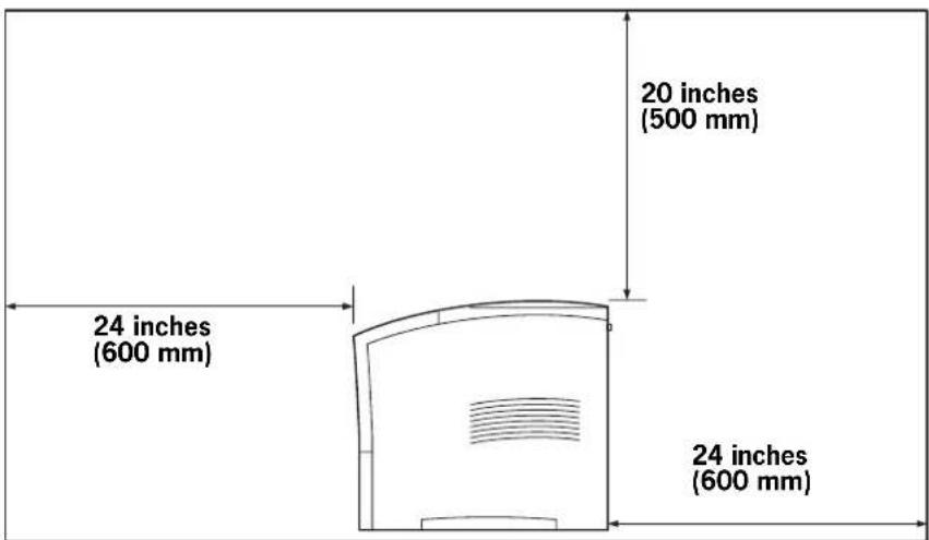
Figure 1-2: Side view of the printer.
Environment
Use the following guidelines to determine the best location for the printer:

natural_image
Line drawing of a desktop computer with an open lid on top (no text or symbols)Horizontal, sturdy, and stable surface

natural_image
Line drawing of a kitchen appliance with a front-mounted oven and curtain window (no text or symbols)Location with good ventilation Location with stable temperature and humidity

and humidity

natural_image
Illustration of a solar panel and a printer with light rays, no text or symbols presentExposed to direct sunlight

natural_image
Illustration of a computer with airflow indicators showing power and cooling system (no text or symbols)Near heating appliances Exposed to direct air currents
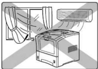
natural_image
Illustration of a washing machine with airflow from a window to a fan (no text or symbols)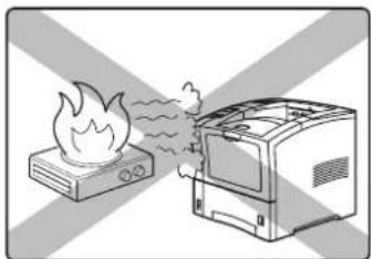
natural_image
Illustration of a boiler emitting steam from a microwave oven (no text or symbols)Near an open flameExposed to high levels of du
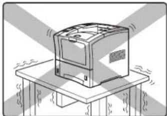
natural_image
Illustration of a desktop computer with ventilation grilles and a base table (no text or symbols)Subject to vibrations

natural_image
Illustration of a bus cleaning machine with smoke and a trash bin nearby (no text or symbols)and contamination

natural_image
Illustration of a kitchen setup with a toaster, refrigerator, and thermometer (no text or symbols)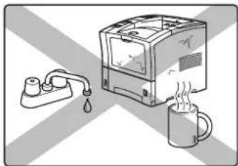
natural_image
Illustration of a water heater with a drop and a mug of steam, set against a diagonal striped background (no text or symbols)Exposed to water and high humidity Exposed to magnetic fields Subject to extreme variations in temperature and humidity
Parts of the Printer
The following figures indicate the names and functions of the main parts of the printer.

Figure 1-3: Front of the Printer.
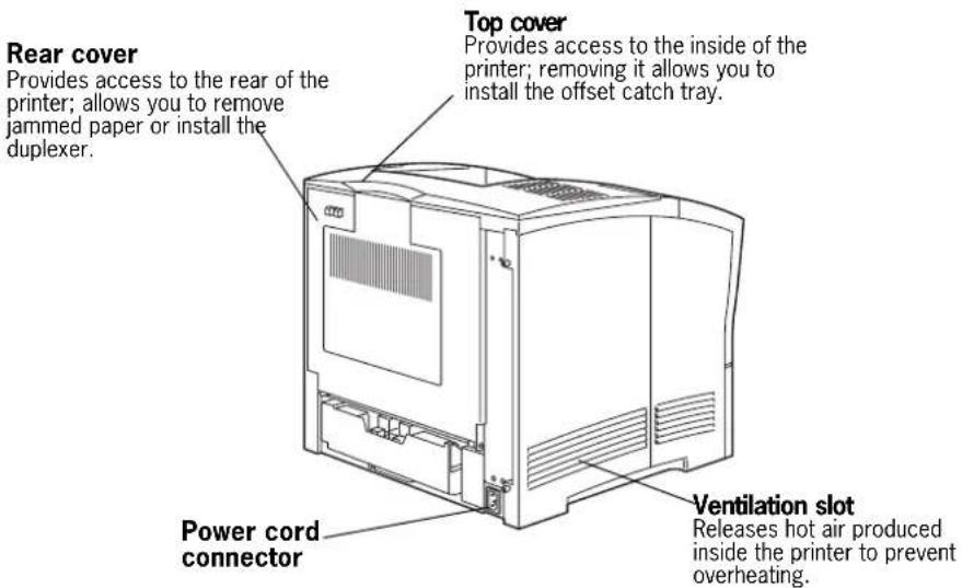
Figure 1-4: Rear of the Printer.

Figure 1-5: Internal Parts of the Printer (Front).

CAUTION: The fuser becomes very hot while the printer is operating. If you need to remove the drum cartridge to remove a paper jam, turn the power off and wait at least 10 minutes before removing the drum cartridge and touching the fuser.

Figure 1-6: Internal Parts of the Printer (Rear).

Figure 1-7: Control Panel.
Optional Printer Accessories
The following figure shows all of the available accessories as installed on the printer:

Figure 1-8: Optional Accessories.
Paper Path
The following figure shows the path that paper travels through the printer:
- The paper is initially fed from the front paper tray or one of the other paper trays.
- The image is transferred from the photosensitive drum onto the paper.
- The fuser fixes the toner permanently on the paper.
-
After passing through the duplexer, if installed, the paper is fed once more through steps (2) and (3).
-
The paper emerges onto the output tray, or the offset output tray if installed.

flowchart
graph TD
    A["1"] --> B["2"]
    B --> C["3"]
    C --> D["4"]
    D --> E["5"]
    E --> F["5"]
    F --> G["1"]
    style A fill:#f9f,stroke:#333
    style B fill:#ccf,stroke:#333
    style C fill:#cfc,stroke:#333
    style D fill:#fcc,stroke:#333
    style E fill:#ffc,stroke:#333
    style F fill:#cff,stroke:#333
    style G fill:#ffc,stroke:#333
Figure 1-9: Paper Path.
Chapter 2
Using the Printer
In this Chapter . . .
■ "About this Chapter" on page 2-2
■ "Connecting the Printer to the AC Outlet" on page 2-2
■ "Turning Power On and Off" on page 2-3
■ "Connecting the Printer to the Host Computer" on page 2-4
■ "Selecting Print Media" on page 2-4
■ "Loading the Universal Paper Tray" on page 2-7
About this Chapter
This chapter provides information concerning the daily use of the printer, including procedures for connecting the printer and loading print media, and guidelines for selecting print media.
Connecting the Printer to the AC Outlet
Use the following procedure to connect the power cord and turn the printer on:
- Insert the power cord into the AC connector on the rear of the printer.

natural_image
Line drawing of a computer monitor with an attached cable and connector, showing internal components and a magnified inset (no text or symbols)- Verify that the power switch of the printer is in the [O] (off) position, then insert the plug of the power cord into the AC outlet.

Turning Power On and Off
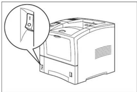
Use the following procedure to turn the printer on:
- Turn the printer on by pressing [ I ] on the power switch on the left front of the printer.
natural_image
Line drawing of a computer monitor with an open lid and magnified inset showing the front panel (no text or symbols)The status message “Loading” appears on the display. This message indicates that the printer is warming up and is not ready to print. After about 65 seconds, the status message changes to “Ready”, indicating that the printer is ready to print.

flowchart
graph LR
    A["Loading"] --> B["Ready"]
NOTE: If an error message appears on the display after you turn the printer on, refer to "Warning Messages and Error Messages" on page 5-26.
Use the following procedure to turn the printer off:
- Turn the printer off by pressing the [O] on the power switch on the right side of the printer.

natural_image
Line drawing of a computer monitor with an inset close-up showing a switch (no text or symbols)Connecting the Printer to the Host Computer
You must connect the printer to your computer using an IEEE 1284 parallel cable or a USB cable. These cables are user-supplied. The parallel and USB ports can be connected simultaneously, and the printer will automatically switch data sources between jobs. Before configuring the printer to the host computer, please install the necessary software drivers from the Electronic Library CD-ROM included with your printer. The CD contains a read-me file which describes driver installation.
Parallel Port
The parallel port conforms to the IEEE 1284 standard. To connect the printer to your computer using the parallel port, simply connect the parallel cable to the parallel port on the printer, then connect the cable to your computer.
USB Port
The USB port provides a reliable, high-speed, bi-directional connection between your printer and PC. The USB standard is designed to deliver complex, graphic-rich documents to the printer with speed and accuracy. The USB port conforms to USB2 standards and operates at a peak rate of 480Mbps. You may use an unpowered USB hub, since the printer is considered a self-powered device and will not draw power from the USB port.
OS Support
The USB port of your printer supports the following operating system environments:
■ Microsoft Windows 2000, and XP
These operating systems come with complete support for USB. You should run USBREADY.EXE from www.usb.org to ensure that Windows 98se, and Millenium are configured correctly.
■ Apple Mac OS 8.6 and above
This version of Apple's operating system ships with the USB equipped systems and contains the necessary code to support USB. No additional software or hardware should be required.
Selecting Print Media
Your printer can print on a variety of media, including plain paper, labels, transparencies, and envelopes. Always use print media that meet the guidelines for use with this printer. Print media that is not recommended for use with this printer may cause frequent paper jams or poor print quality.
Paper and Print Media To Avoid
Do not use paper or print media that has any of the following characteristics:
■ Does not meet the paper and media size and weight specifications for this printer
■ Is not labeled for use with xerographic printers or xerographic copiers
■ Cannot withstand temperatures of up to 310^ F/ 155^ C
■ Is in a sealed package that is obviously damaged or wet
■ Is excessively wrinkled, curled, torn, or warped
■ Is folded or creased
■ Has either an extremely slick surface or an extremely textured surface
■ Has an exposed adhesive surface
■ Has paper pieces glued or taped to the media
■ Has staples or paper clips attached
■ Is categorized as thermal paper, coated paper, or carbon paper
■ Is an envelope that is embossed, is made of extremely thick paper, or is padded
■ Is an envelope that has metal clasps
■ Is an envelope with gummed or adhesive surfaces
■ Is a sheet of labels that has the backing sheet exposed between individual labels
Correct Paper Storage
It is important to store paper correctly prior to placing it in the printer, since improper storage can cause frequent paper jams and poor print quality. Use the following guidelines when storing paper for use in the printer:
■ Store reams of paper on a flat surface, and always store them stacked horizontally.
■ Store reams of paper in an area away from both direct sunlight and high humidity
- Open sealed reams only when you are ready to load the paper into the paper tray, and always close and seal partial reams of paper.
■ Do not stack partial reams of paper.
■ Store paper in a dry area, with a temperature of 10 to 30 degrees Celsius and relative humidity of 30% to 60%.
Print Media Capacities
Your printer can hold up to 1750 sheets of standard weight paper, depending upon the options installed. The printer can be configured in the following three variations:
■ Printer (550 sheets)
■ Printer with 550 sheet feeder(1100 sheets)
■ Printer with two 550 sheet feeders (1650 sheets)
The following table shows the five configurations and the breakdown of paper capacity:
| Front Tray(standard) | Tray 1(standard) | Tray 2(option) | Tray 3(option) | Total PaperCapacity |
| -550 550 | ||||
| 100 550--650 | ||||
| -550 550-1100 | ||||
| 100 550 550-1200 | ||||
| -550 550 550 | 1,650 | |||
| 100 550 550 550 | 1,750 |
If you want to use paper that is an odd size or weight, you must use the front paper tray. The front tray can hold the following quantities of non-standard print media:
■ Envelopes : 10
■ Transparencies: 30
■ Labels: 30
■ Standard Paper: 100
■ Other paper: Stack Height 11.5mm
■ Standard Postcard: 30
Use in Front Tray Do not use

NOTE: Expect a slight reduction in image quality when you print on envelopes, labels, transparencies, or postcards.
Print Media Weight, Type, and Size
The following table defines print media that you can use in each of the paper sources, and also indicates the feed orientation—long edge feed (LEF) or short edge feed (SEF). If you have concerns about a specific brand or type of media, try samples of the media to determine if the resulting printer performance and print quality meet your expectations.
| Paper Source Meter | Weight Paper Type | andFeed Direction | Paper SizesAccommodated |
| Universal Paper Tray(main tray and optional 550 sheet paper feeder)Do not use label stock or other special media in the 550 sheet paper tray. | 60 to 216g/m2 | Any paper Width: | 98.4mm to 215.9mm3.87 to 8.5 inchesLength:148.5mm to 355.6mm5.85 to 14 inches |
| A4 SEF 297 x 210mm | 11.7 x 8.27 inches | ||
| Letter SEF 279.4 x 215 | 9mm11 x 8.5 inches | ||
| Legal 13 inch 330.2 x 215 | 15.9mm13 x 8.5 inches | ||
| Legal 14 inch 355.6 x 215 | 15.9mm14 x 8.5 inches | ||
| Executive SEF 266.7 x 184.5mm | 10.5 x 7.2 inches | ||
| A5 SEF 210 x 149mm | 8.27 x 5.9 inches | ||
| B5 SEF 257 x 182mm | 10.12 x 7.17 inches | ||
| Front Tray 60 to 216g/m2 | EnvelopesTransparenciesLabelsPostcardsStandard Paper (LEF and SEF)Other Paper | Width:3.0 to 8.5 inches76.2mm to 215.9mmLength:5.0 to 14 inches127mm to 355.6mm | |
Loading the Universal Paper Tray
The 550-sheet universal paper tray has two width guides that are located on the sides of the tray, and one length guide that is located near the center of the tray. These guides allow you to adjust the size of the area that holds paper.
NOTE: The following procedure shows you how to load paper into the main paper tray. To load paper into the optional 550 sheet paper feeder, simply complete the procedure using the 550 sheet paper tray and feeder rather than the main paper tray.
Use the following procedure to load paper into the 550 sheet universal paper tray:
- Place the paper tray on a level surface.

natural_image
Technical line drawing of a mechanical device casing with internal compartments and mounting holes (no text or symbols)- Squeeze the length guide, lift it up, and slide it to the rear of the tray.

natural_image
Technical line drawing of a mechanical assembly with an inset magnified view showing internal components (no text or symbols)- If the paper you are using is longer than A4 (297 cm), press the square green button on the bottom of the paper tray to release the rear of the tray, and pull the tray out to extend it.

natural_image
Diagram of hands operating a computer motherboard with arrows indicating process steps (no text or symbols present)- Squeeze the right width guide, lift it up, and slide the guides to the sides of the tray.

natural_image
Technical line drawing of a mechanical assembly with internal components and directional arrows (no text or symbols)- Verify that the plate has dropped down into the base of the paper tray. If the tray is locked in the up potision, pull the lever near the front of the tray to release the plate, or push the paper tray all the way into the printer and then remove it.

natural_image
Technical illustration of a printer's internal structure and external device, showing part assembly and motion arrows (no text or symbols)
CAUTION: Do not overload the tray, and make sure the paper stack is beneath the retaining clips on both sides of the tray. Fan paper before placing it in the tray, and place paper in the tray with the print side up.
- Align the edges of the paper and place it in the center of the paper tray with the side to print on facing down.

natural_image
Technical line drawing of a mechanical assembly with a magnified inset showing a dimension line (no text or symbols present)NOTE: To avoid paper jams and other paper transportation problems, make sure the length and width guides are adjusted to match the paper size and are locked firmly into place.
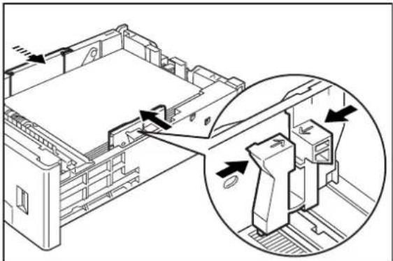
- Squeeze the right width guide, lift it up, and adjust the guides to match the paper width.
natural_image
Technical line drawing of a mechanical assembly with an inset close-up showing internal components (no text or symbols)- Squeeze the length guide, lift it up, and adjust the guide to match the paper length.

natural_image
Technical line drawing of a mechanical assembly with an inset close-up showing internal components (no text or symbols)- Grasp the paper tray with both hands and insert it into the paper tray well on the printer.

natural_image
Line drawing of a person inserting a device into a rack, with an arrow indicating the process (no text or symbols present)- Push the paper tray completely into the printer, making sure the tray is properly seated.

natural_image
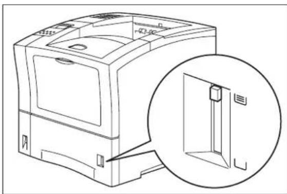
Line drawing of a computer monitor with an open lid and drive base (no text or symbols)- Use the paper level indicator on the front right of the printer to determine when the paper supply is low.
natural_image
Line drawing of a computer case with an inset close-up showing a door mechanism (no text or symbols)Loading the Front Tray
The front tray located on the front of the printer can accommodate a maximum of 100 sheets of paper, and can also accommodate a maximum of 30 sheets of standard labels, transparencies, or postcards, and a maximum of 10 standard envelopes. The tray has two guides that are located on the left and right sides of the tray. These guides allow you to adjust the size of the area that holds the print media. Use the following guidelines when loading the front tray:
- Do not mix print media in the front tray; for example, do not load a stack that includes both envelopes and standard paper. Load only one type of print media.
- Do not mix print media sizes in the front tray; for example, do not load a stack that includes two or more different sizes of paper.
■ Do not load print media that is obviously damaged, wet, creased, or wrinkled.
■ Do not overfill the front tray.
Use the following procedure to load paper in the front tray:
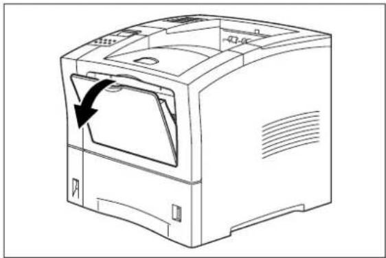
- Open the front tray by pulling the hand grip on the top of the front tray cover.
natural_image
Line drawing of a computer monitor with an arrow indicating the open lid (no text or symbols present)- If you are using paper that is letter size or larger, pull out the input tray extension.

natural_image
Line drawing of a computer printer internal structure with no visible text or symbols- Slide the paper guides so they match the size of the paper that you are loading.

natural_image
Line drawing of a hand inserting a component into a device tray (no text or symbols)-
Stack the paper that you will load in the front tray, making sure that the edges are aligned and neat. Position the paper stack so the surface to be printed faces up.
-
Load the stack of paper into the front tray by sliding the stack between the paper guides and then pushing the paper stack into the tray until it will not go any further.

natural_image
Diagram of a mechanical assembly with two arrows indicating direction (no text or symbols present)- Check the paper stack to make sure it is not loaded at an angle and that the guides barely touch the stack.

CAUTION: Do not press the guides tightly against the stack; the guides should just barely touch the stack of paper. Paper guides that are too tight can cause feed jams.
Chapter 3
Understanding and Navigating the Control Panel Menus
In this Chapter . . .
■ "About this Chapter" on page 3-2
■ "Control Panel Features" on page 3-2
■ "Navigating the Control Panel Menus" on page 3-4
■ "Menu Structure" on page 3-6
■ "Job Library" on page 3-7
■ "Job Accounting" on page 3-8
■ "Paper Menu" on page 3-9
■ "Interface Menu" on page 3-12
■ "PS Menu" on page 3-15
■ "PCL Menu" on page 3-16
■ "System Menu" on page 3-19
■ "Quality Menu" on page 3-21
■ "Functions Menu" on page 3-22
■ "Status Menu" on page 3-23
■ "FLASH Menu" on page 3-23
■ "DISK Menu" on page 3-24
About this Chapter
This chapter explains the control panel and its functions, and also demonstrates how to navigate throughout the various menus and submenus that allow you to view and change the printer settings.
Control Panel Features
The control panel is located on the front of the printer, and contains the display, indicators, and pushbuttons that allow you to view and change the printer settings.
The figure below shows the control panel features.

Figure 3-1: Control Panel.
LCD Display
The LCD display shows status and error messages that inform you of the current status of the printer, and also displays menus, submenus, and printer settings when you are in the menu system. The display contains two lines of text, each with a maximum of sixteen characters.
LED Indicators
The LED indicators also indicate printer status. The four indicators can each be on, off, or blinking, indicating different phases of printer operation. The table below explains the LED indicators.
| LED | Color | When Off | When On | When Blinking |
| Ready ⬤ | Green Printer is NOT READY | Printer is READY N/A | ||
| Active → | Green Printer is IDLE Printer | is ACTIVE (processing a job) | Printer is WAITING (a partial job has been printed, and the printer is waiting for additional job data) | |
| Power ⏻ | Green POWER is off POWER | is on Power Saver Mode ON | ||
| Fault ↓ | Yellow Printer is not in error mode | There is an error that requires user intervention, such as a paper jam, a service call required, etc. | N/A | |
Pushbuttons
The control panel pushbuttons allow you to access and navigate menus, and also assist you in recovering from printer errors. The table below explains the functions of the eight pushbuttons.
| Pushbutton Function | |
Start/Stop ▷/□ | START/STOP—Push this button to start or stop the printer, or to exit the menu system. |
 | MENU—Push this button to enter the menu system. |
 | NEXT—Push this button to move to the next menu, submenu, or setting within the same level of the menu structure. |
 | SELECT—Push this button to select the menu or submenu that is shown on the second line of the display or to choose and save the setting shown on the second line of the display. |
 | CANCEL—Push this button to cancel an action. |
| Pushbutton | Function |
 | STATUS—Push this button to enter the Status Menu and view the current status of printer. |
 | PREVIOUS—Push this button to return to the previous menu, submenu, or option within the same level of the menu structure. |
 | RETURN—Push this button to move up one level in the menu structure to the menu shown on the first line of the display. |
Navigating the Control Panel Menus
When you press the MENU button on the control panel, you enter the printer's menu system. At that point, the first line of the display contains the text "Menu", indicating that you are in the menu system. The second line of the display lists the active menu, which you can change by pressing the NEXT or PREVIOUS button.
Menu Paper Menu
If you press the NEXT button repeatedly, the second line of the display cycles through the main menus in the following order:
■ Paper Menu
■ Interface Menu
■ PS Menu
■ PCL Menu
■ System Menu
■ Quality Menu
■ Functions
NOTE: Additional menus and submenus may appear in the printer menu system when other options are installed.
The following figure shows the sequence of pushbuttons and display messages that would allow you to change the number of copies printed. This example illustrates the basic relationship between menus and submenus and demonstrates how the NEXT, PREVIOUS, SELECT, and RETURN buttons help you to navigate through the menus.

flowchart
graph TD
    A["Menu"] --> B["Menu Paper Menu"]
    B --> C["Next"]
    C --> D["Menu Interface Menu"]
    D --> E["Previous"]
    E --> F["Menu Paper Menu"]
    F --> G["Select"]
    G --> H["Paper Menu Copies"]
    H --> I["Copies 1"]
    I --> J["Next"]
    J --> K["Copies 2"]
    K --> L["Next"]
    L --> M["Copies 3"]
    M --> N["Select"]
    N --> O["Paper Menu Copies"]
    O --> P["Return"]
    P --> Q["Menu Paper Menu"]
Figure 3-2: Navigating the Paper Menu.
- Press the MENU button on the control panel.
- Press the NEXT button until the text "Paper Menu" is shown on the second line of the display.
- Press the SELECT button to enter the paper menu.
- Press the NEXT button until the text "Copies" is shown on the second line of the display.
- Press the SELECT button to enter the copies submenu.
- Press the NEXT or PREVIOUS button to increase or decrease the number of copies printed.
- Press the SELECT button to save this setting.
- Press the START/STOP button to exit the menu system.
Menu Structure
The following figure shows the structure of the control panel main menus and submenus. For more specific information about using and navigating the printer menu system, see the User Guide provided on the Electronic Library CD-ROM.
Job Library
Delete
Job Accounting
Enabled
Print Info
Reset Info
Paper Menu
Copies
Duplex
Duplex Bind
Default Source
Manual Feed
Output Tray
Media Size/Type
Front Tray
Tray 1 Tray 2
Tray 2 (optional) Tray 3 (optional)
Tray Linking
Blank Pages
Output Linking
Front Tray First
Auto Resize
Separator Page
Custom Size
Interface Menu
Port
Parallel
Network Card 1
Parallel Setup
Interpreter
Format
Mode
Delay Out Close
Binary PS
Network 1 Setup
Interpreter
Format
Network address
IP address
Subset mask
Default router
LDP Banner
DHCP
Delay Out Close
Host Name
mDNS Host Name
mDNS Svc Name
Multi-Session
Appletalk
Current Zone
Preferred Zone
Binary PS
USB Setup
Interpreter
Format
Delay Out Close
Binary PS
PS Menu
Print PS Errors
Manual Feed TO
PCL Menu
Orientation
Font Source
Font Number
Pitch
Symbol Set
Macro Filter
Lines Per Page
CR Mode
LF Mode
FF Mode
Print Area
Parameter Values
Paper Source
Paper Size
System Menu
Factory Defaults
Display Language
Powersaver
Wait Timeout
Job Timeout
Jam Recovery
Hex Print
Toner Low
Intellifilter
Quality Menu
Resolution
Toner S aver
Print Density
Functions
Reset Printer
Print Summary
Print Test
Print Fonts
Figure 3-3: Printer Menu Structure.
NOTE: Additional menus and submenus may appear in the printer menu system when other options are installed.
Job Library
- Press the MENU button on the control panel.
- Press the NEXT button until the text "Job Library Menu" is shown on the second line of the display.
- Press the SELECT button to enter the Job Library menu.
- Press the NEXT button to move through the submenus: Print or Delete.
- Press the SELECT button to enter a submenu.
Use the procedures in the following table to access and change the system settings.
| Submenu Default | Setting | Available Settings Procedure for Changing Setting |
| Print Print | User Folder 1 | |
| Print Print | Job1 | |
| Job NamePIN | This step is necessary if the job is a PRIVATE job. | |
| Print Job Name | Copies - Select 1-99 | |
| Print Job Name | Copies | |
| Print Printing | Playback | |
| Delete Delete | (To delete a saved job) | |
| DeleteUser Folder 1 | ||
| DeleteJob1 | ||
| Job NamePIN | This step is necessary if the job is a PRIVATE job. |
Job Accounting
The Job Accounting Menu provides access to functions and settings related to this feature. Use the following procedure to enter the Job Accounting Menu to change the settings or access the functions:
- Press the MENU button on the control panel.
- Press the NEXT button until the text "Job Accounting Menu" is shown on the second line of the display.
- Press the SELECT button to enter the Job Accounting Menu.
- Press the NEXT button to move through the submenus: Enable, Print Info, Reset Info.
- Press the SELECT button to enter a submenu.
Use the procedures in the following table to access and change the system settings.
| SubMenu | Default Settings | Available Settings | Procedure for Changing Setting |
| Enabled No Yes | No | 1. Press NEXT or PREVIOUS to scroll through Yes or No options.2. Press SELECT to choose Yes to turn on this function. | |
| Print Info 1. Press SELECT to begin printing the Job Accounting | Summary Report. | ||
| Reset Info | 1. Press SELECT to reset the Job Accounting Information. This will delete all stored information related to jobs received by the printer. | ||
Paper Menu
The Paper Menu provides access to the printer settings for various paper-handling functions. Use the following procedure to enter the paper menu:
- Press the MENU button on the control panel.
- Press the NEXT button until the text "Paper Menu" is shown on the second line of the display.
- Press the SELECT button to enter the Paper Menu.
- Press the NEXT button to move through the submenus: Copies, Default Source, Manual Feed, Output Tray, Media Size/Type, Tray Linking, Blank Pages, Output Linking, Separator Page, and Custom Size.
- Use the procedures in the following table to access and change the printer paper-handling settings:
| Submenus | Default Setting | Available Settings | Procedure for Changing Setting |
| CopiesThis submenu allows you to change the number of copies printed. | 1 Numbers 1 - 999 | 1. Press NEXT or PREVIOUS to | increase or decrease the number of copies printed.2. Press SELECT to save this setting. |
| DuplexThis submenu allows you to turn the duplexer on or off. | Off | OffOn | 1. Press NEXT or PREVIOUS to toggle between ON and OFF.2. Press SELECT to save this setting. |
| Duplex BindThis submenu allows you to define the binding edge for duplexed sheets. | Long Edge | Long EdgeShort Edge | 1. Press NEXT or PREVIOUS to toggle between LONG EDGE and SHORT EDGE.2. Press SELECT to save this setting. |
| Default SourceThis submenu allows you to choose a default paper source from a list of all installed sources. | Tray 1 | FrontTray 1Tray 2 (optional)Tray 3 (optional) | 1. Press NEXT or PREVIOUS to scroll through the list of available sources of paper.2. Press SELECT to set a source as the default. |
| Manual FeedThis submenu allows you to turn the manual feed on or off. | Off | OnOff | 1. Press NEXT or PREVIOUS to toggle between ON and OFF.2. Press SELECT to save this setting. |
| Output TrayThis submenu allows you to choose a default output tray from a list of all installed output trays. | Face Down Tray | Face Down TrayOffset Tray (optional) | 1. Press NEXT or PREVIOUS to scroll through the list of available output trays.2. Press SELECT to set a tray as the default. |
| Submenus | Default Setting | Available Settings | Procedure for Changing Setting | |
| Media Size/TypeThis submenu allows you to set the media size and type for the Front Tray and set the medial type for all other trays. | Front TraySize: Letter LEFType: PlainTray 1Type: PlainTray 2 (optional)Type: PlainTray 3 (optional)Type: Plain | SizeFront Tray:Letter, A4,B5, A5,Statement,Executive,C5Envelope, DLEnvelope,Com10Envelope,MonarchEnvelope,Legal, Folio,A6 | TypeFront Tray:Plain,Transparency,Prepunched,Letterhead,Colored,Preprinted,Bond, Label,Card Stock,Postcard,Envelope,OtherOther Trays:Plain,Transparency,Prepunched,Letterhead,Colored,Preprinted,Bond, Other | 1. Press NEXT or PREVIOUS to scroll through the list of available sources of paper.2. Press SELECT to choose a tray.3. Press NEXT or PREVIOUS to toggle between MEDIA SIZE and MEDIA TYPE.4. Press SELECT to choose either.5. Press NEXT or PREVIOUS to scroll through the available sizes or types.6. Press SELECT to set a size or type. |
| Tray LinkingThis submenu allows you to turn the tray linking function on or off. | On On | Off | 1. Press NEXT or PREVIOUS to toggle between ON and OFF.2. Press SELECT to save this setting. | |
| Blank PagesThis submenu allows you to choose to either print or not print blank pages of a document. | Print Print | Do Not Print | 1. Press NEXT or PREVIOUS to toggle between PRINT and DO NOT PRINT.2. Press SELECT to save this setting. | |
| Output LinkingThis submenu allows you to turn the output linking function on or off. | Off On | Off | 1. Press NEXT or PREVIOUS to toggle between ON and OFF.2. Press SELECT to save this setting. | |
| Front Tray FirstThis submenu sets the front tray as the default paper source if paper size and type are the same as front tray. | Off On | Off | 1. Press NEXT or PREVIOUS to toggle between ON and OFF.2. Press SELECT to save this setting. | |
| Auto ResizeThis submenu allows you to set the printer to automatically continue the print job when there is a media size mismatch. PostScript print jobs will scale to the nearest paper size, PCL will not scale, but will print on the nearest paper size. | Off On | Off | 1. Press NEXT or PREVIOUS to toggle between ON and OFF.2. Press SELECT to save this setting. | |
| Separator PagePrints a blank page between print jobs. | Off On | Off | 1. Press NEXT or PREVIOUS to toggle between ON and OFF.2. Press SELECT to save this setting. | |
| Custom Size UnitThis menu is used to set the unit of measurement for the Custom Paper Size feature. | Inches Inches | Millimeters | 1. Press NEXT or PREVIOUS to toggle between INCHES and MILLIMETERS.2. Press SELECT to save this setting. | |
Interface Menu
The Interface Menu provides access to the printer interface settings. Use the following procedure to enter the interface menu:
- Press the MENU button on the control panel.
- Press the NEXT button until the text "Interface Menu" is shown on the second line of the display.
-
Press the SELECT button to enter the interface menu.
-
Press the NEXT button to move through the submenus: Port, Parallel Setup, Network 1 Setup, and USB Setup.
-
Use the procedures in the following table to access and change the printer interface settings:
| Submenus Default | Setting | Available Settings | Procedure for Changing Setting |
| PortThis submenu allows you to choose the type of interface. The parallel and USB ports can not be ON simultaneously. | Parallel:OnNetworkCard 1:OnUSB:Off | Parallel :On, OffNetwork Card 1:OnOffUSB:On, Off | 1. Press NEXT or PREVIOUS to toggle between PARALLEL, NETWORK CARD 1, and USB.2. Press SELECT to save this setting. |
| Parallel SetupThis submenu allows you to set up the parallel interface. When the Parallel port is on, the USB port is off. | Interpreter:Auto SwitchFormat:RawMode:BidirectionalDelay OutClose:OffBinary PS:Off | Interpreter:Auto SwitchPCLPostScript 3Format:RawNormalBinaryMode:BidirectionalStandardDelay Out Close:OnOffBinary PS:OffOn | 1. Press NEXT or PREVIOUS to scroll through the submenus.2. Press SELECT to choose a submenu.3. Press NEXT or PREVIOUS to scroll through the settings.4. Press SELECT to choose and save a setting. |
| Network 1 SetupThis submenu allows you to choose to set up the Network interface. | Interpreter:Auto SwitchFormat:RawNetwork Address:IP Address:(user-specified) Subnet Mask:(user-specified) Default Router:(user-specified) LPD Banner:OnDHCP:OnDelay Out Close:OffHost Name:Character string 0-31 charactersmDNS Host Name:Product name and last 3 hex byte values of Network AddressmDNS Svc Name:Product name and last 3 hex byte values of Network AddressMulit-Session:OnAppleTalk:OnBinary PS:Off | Interpreter:Auto SwitchPCLPostScript 3Format:Raw Normal BinaryNetwork Address:IP Address:(user-specified) Subnet Mask:(user-specified) Default Router:(user-specified)LPD Banner:On OffDHCP:OffOnDelay Out Close:OffOnHost Name:mDNS Host Name:mDNS Svc Name:Mulit-Session:On OffAppleTalk:On, OffBinary PS:OffOn | 1. Press NEXT or PREVIOUS to toggle between SPOOLING submenus.2. Press SELECT to choose either submenu.3. Press NEXT or PREVIOUS to scroll through the settings.4. Press SELECT to save this setting. |
| USB SetupThis submenu allows you to choose set up the USB interface. When the USB port is on, the parallel port is off. | Interpreter:Auto SwitchFormat:RawDelay OutClose:OffBinary PS:Off | Interpreter:Auto SwitchPCLPostScript 3Format:RawNormalBinaryDelay Out Close:OffOnBinary PS:OffOn | 1. Press NEXT or PREVIOUS to toggle between INTERPRETER, FORMAT, DELAY OUT CLOSE, and, BINARY PS submenus.2. Press SELECT to choose either submenu.3. Press NEXT or PREVIOUS to scroll through the settings.4. Press SELECT to save this setting. |
PS Menu
The PS Menu provides access to the PostScript settings. Use the following procedure to enter the PS Menu:
- Press the MENU button on the control panel.
- Press the NEXT button until the text "PS Menu" is shown on the second line of the display.
-
Press the SELECT button to enter the PS menu.
-
Press the NEXT button to move through the submenus: Print PS Errors, and Manual Feed TO.
-
Press the SELECT button to enter a submenu.
-
Use the procedures in the following table to access and change the PostScript settings:
| Submenus Default | Setting | Available Settings | Procedure for Changing Settings |
| Print PS ErrorsThis submenu allows you to choose to either print or not print PS errors. | Off On | Off | 1. Press NEXT or PREVIOUS to toggle between ON (print) and OFF (do not print).2. Press SELECT to save this setting. |
| Manual Feed TOThis submenu allows you to set the manual feed timeout—the number of seconds the printer should wait for a manual feed. A setting of 0 will cause printer to wait indefinitely for a manual feed. | 0 0 - 99999 1. | Press NEXT or PREVIOUS to increase or decrease each digit of the five-digit number.2. Press SELECT to move to the next number.3. Press SELECT after setting the last digit to save the setting. | |
PCL Menu
The PCL Menu provides access to the PCL settings. Use the following procedure to enter the PCL menu:
- Press the MENU button on the control panel.
- Press the NEXT button until the text "PCL Menu" is shown on the second line of the display.
- Press the SELECT button to enter the PCL menu.
- Press the NEXT button to move through the submenus: Orientation, Font Source, Font Number, Pitch, Symbol Set, Macro Filter, Lines Per Page, CR Mode, LF Mode, FF Mode, Print Area, and Parameter Values.
- Press the SELECT button to enter a submenu.
- Use the procedures in the following table to access and change the PCL settings:
| Submenus | Default Setting | Available Settings | Procedure for Changing Setting |
| OrientationThis submenu allows you to choose the orientation of the page. | Portrait Portrait | Landscape | 1. Press NEXT or PREVIOUS to toggle between PORTRAIT and LANDSCAPE.2. Press SELECT to choose and save an orientation. |
| Font SourceThis submenu allows you to choose a font source. | Internal Internal 1. | Press NEXT or PREVIOUS to | scroll through the available font sources.2. Press SELECT to choose and set a source. |
| Font NumberThis submenu allows you to set the font number. | 0 Numbers 0-? | 1. Press NEXT or PREVIOUS to increase or decrease the font number.2. Press SELECT to save this setting. | |
| PitchThis submenu allows you to change the pitch of text. | 10.00 | 0.08 - 100.00 | 1. Press NEXT or PREVIOUS to increase or decrease the pitch.2. Press SELECT to save this setting. |
| Submenus | Default Setting | Available Settings | Procedure for Changing Setting | |
| Symbol SetThis submenu allows you to choose a symbol set. | 10U:PC-8 CP437 | 10U:PC-8 CP43711U:PC-8 D/N12U:PC-85017U:PC-8529T:PC-Turkish19U:WIN Latin19E:WIN Latin25T:WIN Latin57J:Desk Top10J:PS Text13J:Ventura Intl14J:Ventura US6J:Microsoft Pub8M:Math-8PS:Math6M:Ventura Math | 15U:Pi Font1U: Legal1E: ISO4 UK0U:ISO6 ASCII0U:ISO11 Swedish0I:ISO15 Italian2S:ISO17 Spanish1G:ISO21 German0D:ISO60 Norweg.1F:ISO69 French9U:WIN3.0 Latin18U:Roman 8ON:ISO 8859-12N:ISO 8859-25N:ISO 8859-5 | 1. Press NEXT or PREVIOUS to scroll through the available symbol sets.2. Press SELECT to choose and set a symbol set. |
| Macro FilterThis submenu allows you to turn the macro filter on or off. | Off On | Off | 1. Press NEXT or PREVIOUS to toggle between ON and OFF.2. Press SELECT to save this setting. | |
| Lines Per PageThis submenu allows you to change the number of lines per page. | 64 5 - 128 1. Press NEXT or PREVIOUS to increase or decrease the lines per page.2. Press SELECT to save this setting. | |||
| CR ModeThis submenu allows you top define the action prompted by a carriage return—a carriage return equals either a cariage return alone, or a carriage return and a line feed together. | CR = CR CR = CR | CR = CR/LF | 1. Press NEXT or PREVIOUS to choose from CR=CR or CR=CR/LF.2. Press SELECT to save this setting. | |
| LF ModeThis submenu allows you to define the action prompted by a line feed—a line feed equals either a line feed alone or a carriage return and a line feed together. | LF = LF LF = LF | LF = CR/LF | 1. Press NEXT or PREVIOUS to choose from LF=LF or LF=CR/LF.2. Press SELECT to save this setting. | |
| FF ModeThis submenu allows you to define the action prompted by a form feed—a form feed equals either a form feed alone or a carriage return and a form feed together. | FF = FF FF = FF | FF = CR/FF | 1. Press NEXT or PREVIOUS to choose from FF=FF or FF=CR/FF.2. Press SELECT to save this setting. | |
| Print AreaThis submenu allows you to expand the print area. | Normal Normal | Expanded | 1. Press NEXT or PREVIOUS to toggle between Normal and Expanded.2. Press SELECT to save this setting. | |
| Parameter ValuesThis submenu allows you to specify which PCL escape sequence papameter values should be associated with each specific selection. | 0 | P0-999Paper Size 0-999 | a | p 1. Press NEXT or PREVIOUS to increase or decrease each digit of the five-digit number.2. Press SELECT to move to the next number.3. Press SELECT after setting the last digit to save the setting. |
System Menu
The system menu provides access to system settings. Use the following procedure to enter the system menu:
- Press the MENU button on the control panel.
- Press the NEXT button until the text "System Menu" is shown on the second line of the display.
- Press the SELECT button to enter the system menu.
- Press the NEXT button to move through the submenus: Factory Defaults, Display Language, Power Saver, Wait Timeout, Job Timeout, Jam Recovery, and Hex Print.
- Press the SELECT button to enter a submenu.
- Use the procedures in the following table to access and change the system settings:
| Submenus | Default Setting | Available Settings | Procedure for Changing Setting | |
| Factory DefaultsThis submenu allows you to reset the printer to U.S. or Non-U.S.factory defaults. | U.S. U.S. | Non-U.S. | 1. Press NEXT or PREVIOUS to toggles between U.S. and NON-U.S.2. Press SELECT to choose and set the factory defaults. | |
| Display LanguageThis submenu allows you to changethe language of the display messages. | English English | FrenchGermanItalianSpanish | 1. Press NEXT or PREVIOUS to scroll through the available languages: English, French (Francais), German (Deutsch), Italian (Italiano), or Spanish (Espanol).2. Press SELECT to choose and set the language. | |
| Power SaverThis submenu allows you to set the number of minutes the printer is idle before it reverts to Power Saver Mode. | 15 0 - 999 1. Press NEXT or PREVIOUS to increase or decrease the number of minutes.2. Press SELECT to save this setting. | |||
| Wait TimeoutThis submenu allows you to increase or decrease the length of time (in seconds) that the printer will remain in the waiting state-a job is being processed, no end-of-file has been detected, and there is no more data to process. This setting applies to both PCL and PostScript print jobs. | 20 0 - 99999 | 1. Press NEXT or PREVIOUS to increase or decrease each digit of the five-digit number.2. Press SELECT set one digit and move to the next digit.3. Press SELECT after changing the last digit to save this setting. | ||
| Job TimeoutThis submenu allows you to increase or decrease the time limit (in seconds) for PostScript jobs. A 0 setting indicates no timeout. This setting applies only to PostScript jobs. | 0 | 0 - 99999 | 1. Press NEXT or PREVIOUS to increase or decrease each digit of the five-digit number.2. Press SELECT set one digit and move to the next digit.3. Press SELECT after changing the last digit to save this setting. | |
| Jam RecoveryThis submenu allows you to turn jam recovery on or off. | On On | Off | 1. Press NEXT or PREVIOUS to toggle between ON and OFF.2. Press SELECT to save this setting. | |
| Hex PrintThis submenu allows you to print hexadecimal characters. | Off On | Off | 1. Press NEXT or PREVIOUS to toggle between ON and OFF.2. Press SELECT to save this setting. | |
| Toner Low Press SELECT to reset the toner page count. | ||||
| Intellifilter 1. | ||||
Quality Menu
The Quality Menu provides access to the printer settings that are related to print quality. Use the following procedure to enter the Quality Menu:
- Press the MENU button on the control panel.
- Press the NEXT button until the text "Quality Menu" is shown on the second line of the display.
- Press the SELECT button to enter the system menu.
- Press the NEXT button to move through the submenus: Resolution, Toner Saver, and Print Density.
- Press the SELECT button to enter a submenu.
- Use the procedures in the following table to access and change the system settings:
| Submenus | Default Setting | Available Settings | Procedure for Changing Setting |
| ResolutionThis submenu allows you to set the resolution (dpi). | 600 dpi 600 dpi | 1200 dpi | 1. Press NEXT or PREVIOUS to scroll through the available resolutions.2. Press SELECT to choose and set the dpi. |
| Toner SaverThis submenu allows you to choose from several toner-saving settings. | Off Off/On 1. Press NEXT or PREVIOUS to scroll through the available toner settings. | ||
| Print DensityThis submenu allows you to adjust the printed image to be lighter or darker. | 5 | 11 - lightest7 - darkest | 1. Press NEXT or PREVIOUS to scroll through the available print density settings.2. Press SELECT to choose and save this setting. |
Functions Menu
The Functions Menu provides access to several printer functions that can supply you with information about the printer and its settings. Use the following procedure to enter the Functions Menu:
- Press the MENU button on the control panel.
- Press the NEXT button until the text "Functions Menu" is shown on the second line of the display.
- Press the SELECT button to enter the system menu.
- Press the NEXT button to move through the available functions: Reset Printer, Print Summary, Print test, and Print Fonts.
- Use the procedures in the following table to execute the functions:
| Functions Procedure for Executing Function | |
| Reset PrinterThis function resets the printer. | Press SELECT to reset the printer. |
| Print SummaryThis function prints a list of all printer settings: | Press SELECT to print a summary of the printer settings. |
| Print TestThis function allows you to print a single test page or a continuous test page. | 1. Press NEXT or PREVIOUS to toggle between SINGLE PAGE and CONTINUOUS.2. Press SELECT to print the test page(s). |
| Print FontsThis function allows you to print Postscript or PCL font lists. | 1. Press NEXT or PREVIOUS to toggle between POSTSCRIPT and PCL.2. Press SELECT to select and print the specific fonts list. |
Status Menu
In addition to the main menus listed above, the printer also provides a status menu that allows you to view the current settings for the input and output trays and the toner cartridge. Use the following procedure to enter the Status Menu:
- Press the STATUS button on the control panel.
-
Press the NEXT button to move through the submenus: Front, Tray 1, Tray 2, Tray 3, Face Down, and Toner.
-
Press the SELECT button to enter a submenu.
-
Use the procedures in the following table to view the status of the printer:
| Submenu Procedure for Executing Function | |
| FrontThis submenu allows you to view the current Media Size and Media Type for the front tray. | 1. Press NEXT or PREVIOUS to scroll through the media size, media type, and level settings for the Front Tray.2. Press SELECT to view a specific setting. |
| Tray 1This submenu allows you to view the current Media Size, Media Type, and Level for Tray 1. | 1. Press NEXT or PREVIOUS to scroll through the media size, media type, and level settings for Tray 1.2. Press SELECT to view a specific setting. |
| Tray 2This submenu allows you to view the current Media Size, Media Type, and Level for Tray 2. | 1. Press NEXT or PREVIOUS to scroll through the media size, media type, and level settings for Tray 2.2. Press SELECT to view a specific setting. |
| Tray 3This submenu allows you to view the current Media Size, Media Type, and Level for Tray 3. | 1. Press NEXT or PREVIOUS to scroll through the media size, media type, and level settings for Tray 3.2. Press SELECT to view a specific setting. |
| Face Down TrayThis submenu allows you to view the status of the face down tray. | 1. Press SELECT to view the status of the Face Down Tray. |
| TonerPress SELECT to view the status of the toner cartridge. | |
FLASH Menu
NOTE: This menu will only appear if an optional FLASH DIMM has been installed in the FLASH DIMM slot. Consult the documentation that came with your FLASH DIMM for detailed installation and usage instructions.
The FLASH Menu provides access to the printer settings that are related to the optional FLASH DIMM. Use the following procedure to enter the FLASH Menu:
- Press the MENU button on the control panel.
-
Press the NEXT button until the text "FLASH Menu" is shown on the second line of the display.
-
Press the SELECT button to enter the system menu.
- Press the NEXT button to move through the submenus: Print, Delete, Format FLASH, and FLASH summary.
- Press the SELECT button to enter a submenu.
- Use the procedures in the following table to access and change the system settings:
| Submenus Procedure for Changing Setting | |
| PrintThis selection will read the selected file from FLASH and print it as if it were being received from one of the input ports. | 1. Press NEXT or PREVIOUS to scroll through the files.2. Press SELECT to choose and print the file. |
| DeleteThis selection will delete the selected disk file or directory from the FLASH DIMM. To delete an entire directory, you must first delete all the files within that directory. | 1. Press NEXT or PREVIOUS to scroll through the files.2. Press SELECT to choose and delete the file. |
| Format FlashThis selection will reformat the FLASH DIMM. | 1. Press SELECT to reformat the FLASH DIMM. |
| Flash SummaryThis selection will print a page containing information about the installed FLASH DIMM including a list of all the current existing files and directories. | 1. Press SELECT to print the FLASH summary. |

WARNING! All files on the FLASH DIMM will be deleted if the Format FLASH function is selected.
DISK Menu
NOTE: This menu selection will only appear if an optional hard disk drive has been installed. Consult the documentation that came with your hard disk drive for detailed installation and usage instructions.
The Disk Menu provides access to the printer settings that are related to the optional Hard Disk. Use the following procedure to enter the Disk Menu:
- Press the MENU button on the control panel.
- Press the NEXT button until the text "Disk Menu" is shown on the second line of the display.
-
Press the SELECT button to enter the system menu.
-
Press the NEXT button to move through the submenus: Print, Delete, Format Disk, and Disk Summary.
-
Press the SELECT button to enter a submenu.
-
Use the procedures in the following table to access and change the system settings:
| Submenus Procedure for Changing Setting | |
| PrintThis selection will read the selected file from Disk and print it as if it were being received from one of the input ports. | 1. Press NEXT or PREVIOUS to scroll through the files.2. Press SELECT to choose and print the file. |
| DeleteThis selection will delete the selected disk file or directory from the hard disk. To delete an entire directory, you must first delete all the files within that directory. | 1. Press NEXT or PREVIOUS to scroll through the files.2. Press SELECT to choose and delete the file. |
| Format DiskThis selection will reformat the hard disk. | 1. Press SELECT to reformat the hard disk. |
| Disk SummaryThis selection will print a page containing information about the installed hard disk, including a list of all the current existing files and directories. | 1. Press SELECT to print the Disk summary. |

WARNING! All files on the hard disk will be deleted if the Format Disk function is selected.
Chapter 4
Maintaining the Printer
In this Chapter . . .
■ "About this Chapter" on page 4-2
■ "Upgrading Printer Firmware" on page 4-2
■ "Replacing Printer Components" on page 4-3
■ "Cleaning the Printer" on page 4-18
■ "Moving the Printer" on page 4-21
■ "Storing the Printer for Long Periods of Time" on page 4-22
About this Chapter
This chapter provides information about maintaining your printer. Although the printer requires very little maintenance, with normal daily use you will need to perform some routine maintenance procedures, including replacing consumable items and cleaning the printer. This chapter also contains information about moving and storing the printer.
Upgrading Printer Firmware
The executable firmware for the printer controller is stored in FLASH memory. You can easily upgrade this firmware on site when a new version of code is available. The upgrade process involves sending the new code, which is usually named with a .LOD extension, to the printer using either the parallel or network interface. When the printer receives the file, it will automatically recognize it as a firmware upgrade file and will program it into the FLASH memory. During this process the printer will display information about each sub-file that it is receiving or programming. When finished, the printer displays the text “Upgrade Completed” and reboots, executing the new firmware.
Contact your dealer or service provider for more information about firmware upgrades.
Upgrading Firmware Using the Parallel Interface
To upgrade the printer using the parallel interface, go to the DOS prompt and use the copy command to copy the new file to the printer. For example, type “copy newversion.lod/b lpt1” at the DOS prompt, where “newversion” is the name of the firmware upgrade file and “lpt1” is the printer you would like to upgrade. Be sure to use the “/b” switch on the copy command line to ensure that the data is sent in binary mode.
| NOTE: | If you are using a PC that is not running Windows or if you do not have any printer drivers installed and configured to use the parallel interface, you will need to configure the parallel port for permanent retry by entering the following command PRIOR to entering the copy command discussed above: mode lpt1:,,p |
| If you are running Windows, you may get an error message during the upgrade process that indicates that the printer is busy or that there is a printer error. This message box will contain check-boxes for “Retry” or “Cancel”. DO NOT SELECT CANCEL. This error message is only a result of the printer programming a large file into FLASH memory and will disappear once the programming is completed. |
Upgrading Firmware Using the Network Interface
To upgrade printer firmware using the network interface, simply send the new file to the printer using whatever procedure you normally use to send a print file. This procedure varies depending on the network environment.
Replacing Printer Components
Replacing the Toner Cartridge
The toner cartridge contains the dry ink as well as the xerographic drum and associated components that create the xerographic image on a sheet of paper. The toner cartridge will eventually run out of ink through normal use. When the toner is low, printed images will be uneven or very light. Use the following guidelines when using or storing a toner cartridge:
■ An unopened and correctly stored toner cartridge has a shelf life of approximately two years.
- Do not open the box containing the toner cartridge until you are ready to install the cartridge into the printer.
■ Store the toner cartridge box horizontally—not on end.
- Keep the cartridge out of the reach of children, and in an area where the temperature remains between 32°F and 95°F and the humidity remains between 15% to 85%. If you bring a cold toner cartridge into a warm room, wait a least an hour for the temperature to stabilize before opening the cartridge box.
■ Do not disassemble the toner cartridge.
- Toner is a safe material, but if you get any on your hands DO NOT wash them in hot water. Use only cold water to wash off toner. Hot water sets the toner and makes it difficult to remove.
- A shutter protects the photosensitive drum from ambient light. Do not open the drum shutter by hand.


CAUTION: Do not expose the new toner cartridge to strong light for more than a few minutes before installing it into the printer.

WARNING! Do not dispose of used toner cartridges in an incinerator or in an open fire.
Use the following procedure to replace the toner cartridge:
-
Place a drop-cloth or some paper on the table or floor near the printer.
-
Press the button on the top of the printer to open the front cover, and pull the cover all the way open.

natural_image
Line drawing of a computer printer with an open lid and directional arrows indicating motion (no text or symbols)- Remove the old toner cartridge from the printer and carefully place it on the drop-cloth.
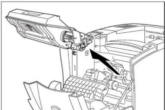
natural_image
Technical line drawing of a mechanical assembly with an arrow indicating a component (no text or symbols present)-
Remove the new toner cartridge from its packaging.
-
Rock the toner cartridge back and forth and then shake it horizontally to ensure that the toner is evenly distributed.
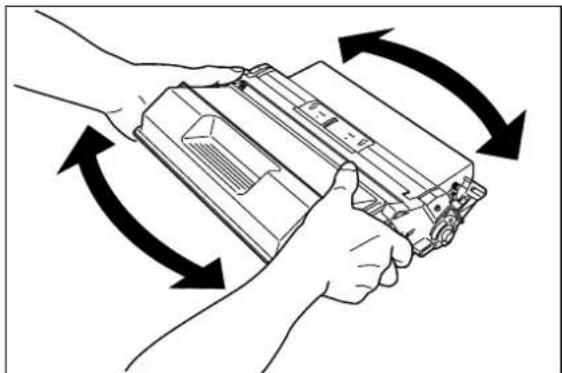
natural_image
Illustration of hands holding a device with bidirectional arrows indicating rotation or movement (no text or symbols)- Grasp the toner cartridge firmly and pull the sealing tape straight out from the cartridge.

natural_image
Line drawing of hands inserting a device into a folder (no text or symbols)- Slide the pegs on the toner cartridge into the channels on the inside of the printer, and lower the toner cartridge into the printer.

natural_image
Technical line drawing of a mechanical assembly with no visible text or symbols- Close the front cover.

natural_image
Line drawing of a computer printer with a hand operating the front panel (no text or symbols present)Disposing of the Print Cartridge
-
Place the used toner cartridge inside the new toner cartridge box and seal the box.
-
Dispose of or recycle the used toner cartridge.

WARNING! Do not dispose of the old toner cartridge in an incinerator or in an open fire.
Replacing the Fuser
The fuser melts the toner image into the paper to form a finished print. The fuser wears with normal use and can leave dirt or marks on printed sheets when worn. The normal life of a fuser is approximately 200,000 A4/Letter size prints at 5% area coverage. Running high image density prints or large format paper will cause the fuser life to be shorter.

WARNING! The fuser becomes very hot during operation. Do not touch the fuser until it is cool.
NOTE: In the following procedure, the left and right sides of the printer are those to the left and right of a person facing the rear of the printer.
NOTE: If you are using the duplexer, refer to "Chapter 6 Using the Duplexer" and remove the duplexer before attempting to replace the fuser.
Use the following procedure to remove and replace the fuser:
- Turn the printer off by pressing the [O] on the power switch on the front of the printer, and disconnect the AC power cord from the wall outlet. Wait at least 30 minutes before proceeding to remove the fuser.

natural_image
Line drawing of a printer with two views: one showing a close-up of the front panel and another showing a close-up of the right panel (no text or symbols present)- Squeeze the tabs on the top of the rear cover, and pull the cover toward you to open it.

- Remove the screws that secure the fuser to the printer.

natural_image
Technical diagram of an internal computer or server unit with a magnified inset showing mechanical components (no text or symbols visible)- Grasp the metal brackets on the sides of the fuser and pull the fuser toward you to remove it from the printer.

natural_image
Illustration of hands operating a computer tower with an open drive (no text or symbols visible)-
Remove the new fuser from its packaging, and remove any shipping tape or spacers.
-
Insert the new fuser into the printer, making sure it is securely seated.

natural_image
Technical line drawing of an open industrial machine with internal components and a rack (no text or symbols)- Secure the fuser to the printer by replacing and tightening the screws.
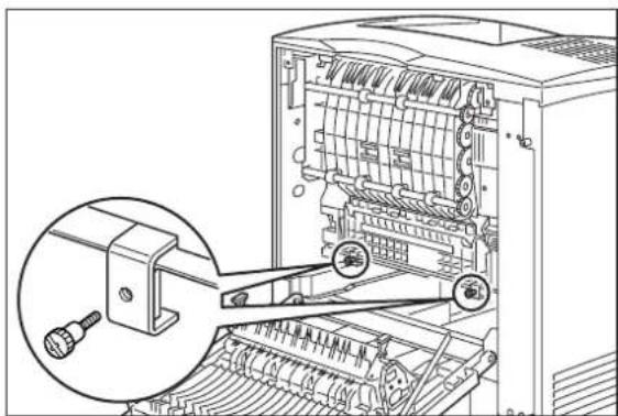
natural_image
Technical diagram of a computer tower with an inset showing a cable connector (no text or symbols present)- Close the rear cover.

natural_image
Line drawing of a computer case with an arrow indicating rotation or movement (no text or symbols present)- Verify that the power switch of the printer is in the [O] (off) position, then insert the plug of the power cord into the AC outlet.
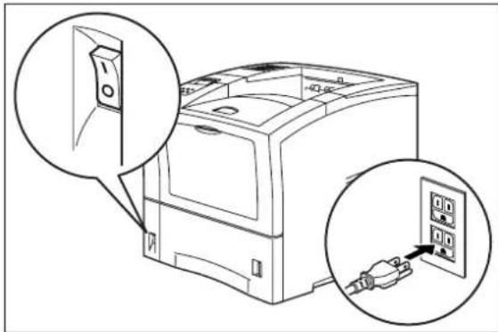
natural_image
Line drawing of a computer with an open door and two connected outlets (no text or symbols)- Turn the printer on by pressing [I] on the power switch on the front of the printer.
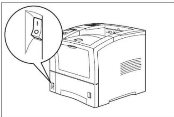
natural_image
Line drawing of a computer printer with an open lid and magnified view of its front panel (no text or symbols)Replacing Feed Roll, Nudger Roll, and Retard Roll
Rubber feed rolls drive sheets of paper out of the feeder paper trays into the printer. These feed rolls wear with normal use and eventually become coated with paper dust and must be replaced. Frequent feed jams in the front tray or main tray indicate that the feed rolls need to be replaced.
NOTE: The following procedure illustrates the process of replacing the feed roll, retard roll, and nudger roll for the main paper tray. To replace the rolls for a paper feeder, use the same procedure but remove the paper tray of the paper feeder and replace the feed rolls in the paper tray well of that feeder.
- Turn the printer off by pressing the [O] on the power switch on the right side of the printer, and disconnect the AC power cord from the wall outlet.

natural_image
Line drawing of a computer with two views: one showing a close-up of a switch, the other showing a close-up of a connected power strip (no text or symbols)- Remove the paper tray of the feeder that you intend to replace rolls on and set it on a flat level surface.

natural_image
Line drawing of a computer monitor with an open lid and drive button (no text or symbols)- Pull the metal stopper plate down.
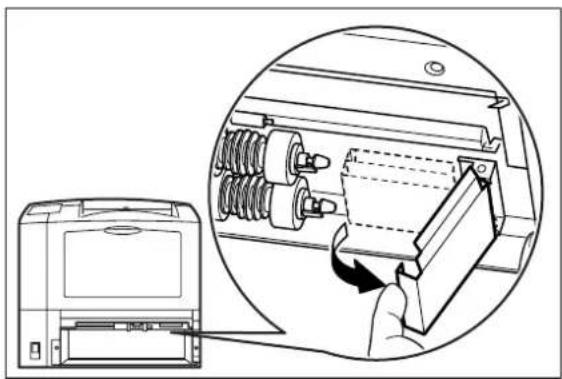
natural_image
Diagram showing a computer monitor with a magnified inset of its internal components (no text or symbols visible)- Unclip the retaining tabs on the end of the feed roll and nudger roll, and remove the rolls from their shafts.

natural_image
Mechanical assembly diagram showing spring components and a close-up of a mechanical component (no text or labels)- Push the new feed roll and nudger roll onto their shafts until the retaining tabs click into place. Make sure the tabs are toward the right side of the printer.
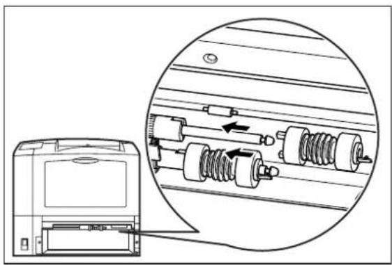
natural_image
Diagram showing a device with internal components and a magnified inset view of mechanical parts (no text or symbols)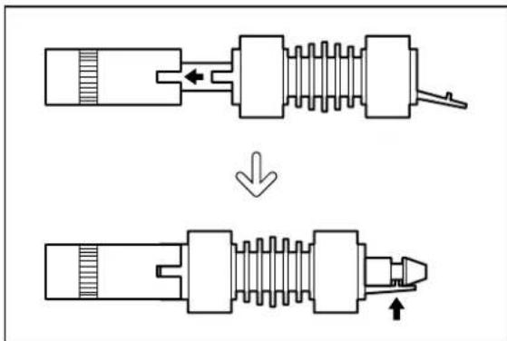
- Release the metal stopper plate inside the printer so it returns to its normal position.

natural_image
Technical line drawing of a mechanical device with an inset view showing internal components (no text or symbols)- Press the locks on the left and right of the retard roll inside the paper tray, and lift the lever to open the retard roll cover.

- Unclip the retaining tab on the retard roll and remove it from the shaft.

- Push the new retard roll onto the shaft until the retaining tab clicks into place. Make sure the retaining tab is toward the right side of the printer.

- Close the retard roll cover.

natural_image
Technical line drawing of a mechanical assembly with two arrows indicating directional components (no text or symbols present)- Grasp the paper tray with both hands and insert it into the paper tray well on the printer.

natural_image
Line drawing of hands installing or adjusting a mechanical component into a rack (no text or symbols visible)- Push the paper tray all the way into the printer, making sure the tray is properly seated.

natural_image
Line drawing of a computer monitor with an open door and internal panel (no text or symbols)Replacing the BTR Roller
The BTR roller assists in the transfer of the image to the paper. The BTR wears with normal use. The normal life of the BTR is about 200,000 A4/letter size prints. Use the procedure below to replace the BTR roller:
- Turn the printer off by pressing [O] on the power switch on the front of the printer, and disconnect the power cord from the AC wall outlet.

natural_image
Line drawing of a printer with two views: one showing a close-up of the cover and another showing a close-up of the internal socket (no text or symbols present)- Push the button on top of the printer to release the front cover, and pull the front cover toward you to open it.

natural_image
Line drawing of a computer printer with an open lid and directional arrows indicating rotation (no text or symbols)- Remove the toner cartridge from the printer.
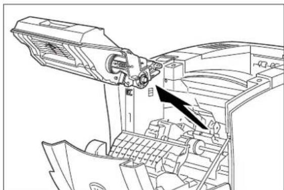
natural_image
Technical line drawing of a mechanical assembly with no visible text or symbolsNOTE: To prevent stains, place the toner cartridge on some old newspaper or other disposable surface.
- Raise the BTR roller by pressing the two levers on the left and right sides of the plate that sits behind the BTR roller.

natural_image
Technical line drawing of a printer internal structure with two circular insets showing mechanical components (no text or symbols)
CAUTION: Do not touch the surface of the BTR with your fingers. Contaminating the BTR will cause deletions on the printed page.
- Holding both ends of the BTR roller, pull it toward you and llift it out of the printer.

natural_image
Diagram of a computer motherboard showing internal components and a scroll wheel (no text or labels)- Position the new BTR roller so the gear is at the right end of the roller. Insert the left end of the shaft into the left clip inside the printer, then insert the right end into the right clip.

- Press the BTR roller down until it locks firmly in place.
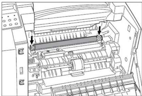
natural_image
Technical diagram of a printer internal structure showing internal components and a scroll wheel (no text or labels)- Insert the pegs on the toner cartridge into the channels inside the printer, and push the toner cartridge into the printer.

natural_image
Technical line drawing of a mechanical assembly with no visible text or symbols- Close the front cover, pressing on the center of the cover until it locks firmly in place.

natural_image
Line drawing of a hand operating a computer with an arrow indicating rotation (no text or symbols present)Cleaning the Printer
Cleaning the Exterior
The covers and tray faces of the printer may collect dust and dirt through normal use. Although exterior dirt should not affect printer performance, an occasional exterior cleaning helps maintain the appearance of the printer appearance. Use the following procedure to clean the exterior of the printer:
- Turn the printer off by pressing the [O] on the power switch on the right side of the printer, and disconnect the AC power cord from the wall outlet.

- Using a soft cloth that is slightly damp with cold water, wipe the printer covers and tray faces. Use a very mild, non-abrasive soap to remove heavy dirt and toner stains.
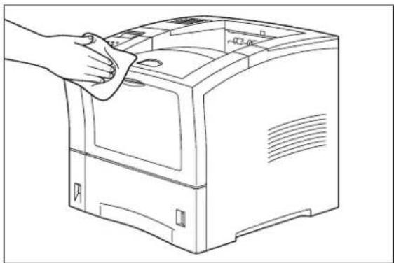
natural_image
Line drawing of a hand cleaning a computer with a cloth (no text or symbols)
Do not use solvents or abrasive cleaners to clean printer covers. Use only cold water and a very mild soap.
-
Use a soft, dry cloth to thoroughly dry the covers and tray faces.
-
Verify that the power switch of the printer is in the [O] (off) position, then insert the plug of the power cord into the AC outlet.
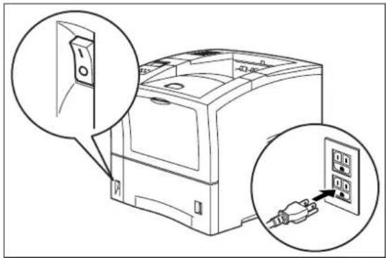
- Turn the printer on by pressing [I] on the power switch on the right side of the printer.

natural_image
Line drawing of a computer printer with an open lid and magnified view highlighting the front panel (no text or symbols present)Cleaning the Interior
The interior of the printer does not generally need to be cleaned unless a paper jam drops toner onto the paper path or you accidentally spill toner inside the printer when installing a new toner cartridge. Use the following procedure to clean the interior of the printer only when necessary:

Since there is always the possibility of damaging delicate printer components by carelessness or vigorous cleaning methods, it is recommended that you clean the interior only when you are instructed to do so by a service representative or in a troubleshooting procedure presented in this manual.
- After removing a paper jam or replacing the toner cartridge, remove any paper scraps from inside the printer and wipe off paper dust with a clean, dry cloth.

natural_image
Line drawing of a hand cleaning a computer motherboard with visible internal components (no text or symbols)Moving the Printer
Follow the guidelines below when lifting or moving the printer:
- The printer is very heavy, and should always be lifted by two people. The weight of the printer without paper tray, toner cartridge, and paper is about 55 lbs (25 kg). Never attempt to lift the printer alone.

natural_image
Line drawing of two hands holding a rectangular object with a textured surface (no text or symbols)- To lift the printer, have two individuals facing each other from the front and the rear of the printer grasp the recessed areas on each side of the printer. Do not lift the printer by grasping any area other than these recessed areas.
■ When lifting the printer, maintain proper lifting posture to prevent injuries.
Moving the Printer a Short Distance
Use the following procedure to move the printer a short distance:
-
Turn the printer off by pressing the [O] on the power switch on the back of the printer.
-
Unplug the AC power cord from the AC wall outlet.
-
Disconnect the printer from the host computer.
-
Wait 30 minutes for the printer to cool.
-
Refer to Chapters 6 through 9 for instructions on moving installed paper-handling options.
-
Remove the toner cartridge and cover it with an opaque plastic sheet.
-
Move the printer to the new location.
-
Once the printer is in the new location, refer to the Installation Guide included in the original printer packaging for installation instructions.
Moving the Printer a Long Distance
Use the following procedure to move the printer a long distance:
-
Turn the printer off by pressing the [O] on the power switch on the right side of the printer.
-
Unplug the AC power cord from the wall outlet and from the back of the printer.
-
Disconnect the printer from the host computer.
-
Remove the paper from all of the paper trays.
-
Wait 30 minutes for the printer to cool.
-
Remove all installed paper-handling options. Refer to Chapters 6 through 10 for instructions for removing installed paper-handling options.
- Remove the toner cartridge and place it in an opaque plastic bag, then seal the bag with tape and place it in a sturdy box.
- Repack the printer, paper trays, AC power cord and toner cartridge into the original shipping box or boxes.
- Once the printer is in the new location, refer to the Installation Guide included in the original printer packaging for installation instructions.
Storing the Printer for Long Periods of Time
If you will not be using the printer for several months, use the following procedure to prepare the printer for storage:
- Turn the printer off by pressing the [O] on the power switch on the right side of the printer.
- Unplug the AC power cord from the AC wall outlet.
- Disconnect the printer from the host computer.
- Remove the paper from all of the paper trays.
- If you will be storing the printer for six months or longer, remove the toner cartridge and place it in an opaque plastic bag, and seal the bag with tape.
NOTE: After prolonged inactivity the toner cartridge may degrade to the point where it is no longer usable and must be replaced. Poor print quality and frequent paper jams may indicate that the toner has solidified and that the drum has oxidized during storage.
- Cover the printer with a plastic sheet and tape down the corners.
- Store the printer in an area where the temperature and humidity are moderate, as described in "Environment" on page 1-5.
NOTE: Do not stack other items on top of the printer when storing the printer.
Chapter 5
Troubleshooting
In this Chapter . . .
■ "About this Chapter" on page 5-2
■ "Installation Problems" on page 5-2
■ "Paper Jams" on page 5-4
■ "Print Image Quality Problems" on page 5-18
■ "Miscellaneous Problems" on page 5-22
■ "Warning Messages and Error Messages" on page 5-26
About this Chapter
This chapter describes the problems that you may encounter when using your printer, and provides procedures for resolving the problems. This chapter also lists the warning and error messages that appear on the control panel display.
There are four basic types of printer problems:
■ Installation problems
If there is a problem with the printer when you first turn in on, refer to “Installation Problems” on page 5-2 for information about possible installation problems.
■ Paper Jams
If there is a paper jam, refer to “Paper Jams” on page 5-4 for procedures to remove the jam.
■ Print quality problems
If the finished prints delivered to the output tray display image problems such as image black spots or vertical lines on the page, refer to “Print Image Quality Problems” on page 5-18 and complete the procedure provided for the specific image problem that you have encountered.
■ Miscellaneous problems
If you have a printer problem but the control panel does not display a warning message or error message, refer to “Miscellaneous Problems” on page 5-22 and follow the directions for correcting that problem.
Many of these printer problems are indicated by a warning or error message appearing on the control panel display. If the printer control panel displays a warning message or error message, refer to "Warning Messages and Error Messages" on page 5-26 and complete the actions prescribed for the specific warning or error message.
Installation Problems
It is common for simple oversights during printer installation to cause problems when you first turn the printer on, resulting in noise, smoke, or smell; an inoperative printer; or the absence of a ready message on the control panel.
Inoperative Printer
If you have problems turning on the printer, check the possible causes listed in the table below. If the printer will not start after checking these items, turn the printer off, disconnect the power cord from the AC outlet, and contact your dealer or an authorized service provider.
| Description Possible Cause Action | ||
| There is no power. The power switch is not set to [1] (on). | Check the power switch.See “Step 7: Connecting the Power Cord and Turning the Printer On” on page 1-19. of the Installation Guide. | |
| The power cord is not properly plugged into an AC outlet or into the AC connector on the rear of the printer. | ||
| Voltage of the AC power is not correct. | ||
| The fuse on the power cord is not functioning. (UK only) | ||
| The AC wall outlet is not functioning. | ||
| There is interference from other electrical devices on the same circuit. | ||
| Thermal sensors may have shut down the printer. | ||
| Power is frequently interrupted. | The printer is malfunctioning. Turn the printer off and disconnect the power cord from the AC outlet. Contact your dealer or an authorized service provider. | |
No Ready Message
After warming up, the printer control panel displays the text “Ready”, indicating that the printer is ready to print. If the printer does not show this message, but shows an error message instead, refer to “Warning Messages and Error Messages” on page 5-26 to determine the appropriate action for the specific error message that is shown. If the printer does not display either the “Ready” message or an error message, contact your retailer or sales representative.
Noise, Smoke, or Smell
If you notice unusual noise, smoke, or smell after turning the printer on, turn the printer off immediately and disconnect it from the AC wall outlet. Use the following procedure to determine the cause of and alleviate the problem:
- Refer to the pictorial unpacking sheet and the Installation Guide included in the printer packaging and make sure you have removed all shipping spacers and protective tape from the inside of the printer, the paper trays, and the toner cartridge.
- Open the covers on the printer and carefully inspect the fuser area. Remove any pieces of paper that may be stuck in the fuser.
- Check the inside of the printer for any obviously broken or detached parts. If you find a broken part, contact your retailer or sales representative.
- Check the exterior of the printer for broken covers. If you find a broken cover, contact your retailer or sales representative.
- Verify that the AC wall outlet is the correct voltage for your printer.
- Remove any paper you have loaded in the main tray, check the inside of the tray well for stray sheets of paper, and reload the paper into the main tray.
- Connect the printer to the AC wall outlet and turn the printer on by pressing the [I] on the power switch on the right side of the printer.
- If this procedure does not eliminate the noise, smoke or smell, or if the problem returns, turn the printer off, unplug the AC power cord from the AC wall outlet, and contact your retailer or sales representative.
Paper Jams
Paper jams are generally the most common and reoccurring problem encountered when using any printer. Paper may jam anywhere along the paper path—from the paper tray to the output tray. Sensors within the printer constantly monitor paper travel, so when a sheet of paper fails to arrive at a certain point within a specific time, the printer interprets that to mean that the paper has stopped between two sensors along the paper path. The printer then displays a Paper Jam error message that corresponds to that specific jam.
When paper gets jammed inside the printer, printing stops and an error code indicating the position of the jam appears on the display.
| Error Code Paper Jam Location | |
| E2 Between the paper feed section (front paper tray, main tray, or optional feeder tray) and the toner cartridge | |
| E3 Between the toner cartridge and the fuser unit | |
| E4 At the paper exit slot | |
| E6 At the offset output tray | |
| E7 At the duplexer |

Figure 5-1: Paper Jam Locations and Error Codes.
The most common causes of paper jams are:
■ The printer is not placed on a level surface.
■ The print media does not conform to the specifications.
■ The paper is not loaded correctly in the front paper tray or the cassette.
■ The paper is wrinkled or curled.
■ The paper guide is not set correctly.
Occasional paper jams result from simple things such as static electricity sticking paper together—causing several sheets to feed at the same time—or from the feed rolls becoming slippery from an accumulation of paper dust. Occasional paper jams usually require minor user intervention that involves reloading the paper or cleaning the feed rolls.
Frequent paper jams can be caused by anything from foreign material in the paper path to a broken or malfunctioning component. Frequent paper jams may require involved user intervention that includes replacing a consumable item or calling a service technician to troubleshoot and correct the problem.
Clearing an E2 Paper Jam
If an E2 error code precedes the error message on the first line of the control panel display, paper has jammed somewhere between the feed area and the registration sensor. Use the following procedure to clear a paper jam in this location:
-
Remove any printed pages from the output tray.
-
If the jam occurred while feeding from the front paper tray, remove all paper from the front tray, including any paper that may be jammed inside the tray.

natural_image
Line drawing of a bed with a black arrow indicating downward motion (no text or symbols)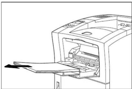
natural_image
Line drawing of a printer internal structure with paper feed and paper tray (no text or symbols)- If the jam occurred while feeding from the main paper tray, remove the main paper tray.

natural_image
Line drawing of a person inserting a component into a rack device (no text or symbols)- Remove any jammed or wrinkled paper from the paper tray.

natural_image
Line drawing of a computer motherboard showing internal components and a black arrow indicating motion (no text or symbols)-
Remove any jammed paper from the inside of the paper tray well.
-
If the jam occurred while feeding from Tray 2 or 3, remove the paper tray associated with that feeder and remove any jammed paper.
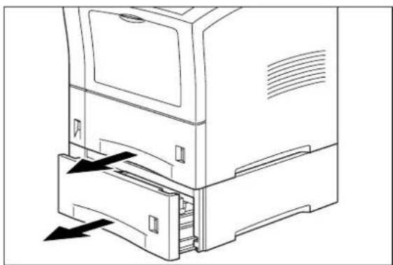
natural_image
Line drawing of a computer tower with an open drawer and black arrows indicating motion (no text or symbols)
natural_image
Technical line drawing of a computer motherboard with an arrow indicating compression or shift (no text or symbols present)-
Remove any jammed paper from the inside of the paper tray well.
-
Insert each paper tray into the appropriate paper tray well, either on the optional feeder or on the printer.
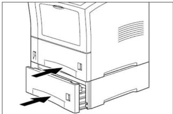
natural_image
Line drawing of a computer tower with an open drawer and directional arrows indicating movement (no text or symbols)- If the front tray is open, close it. Then pull on the recessed area on the front cover to open it.
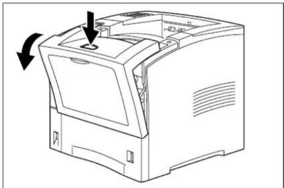
natural_image
Line drawing of a computer printer with an open lid and directional arrows indicating rotation (no text or symbols)- Return the front cover to its original position, pressing on the center of the cover to close it securely.

natural_image
Line drawing of a hand inserting a printer into a paper airplane (no text or symbols)Clearing an E3 Paper Jam
If an E3 error message appears on the printer display, there is a paper jam between the toner cartridge and the paper exit slot. Use the following procedure to remove a paper jam from this location.
-
Remove any printed sheets from the output tray.
-
Remove all paper from the front tray.
-
Press the button on the top of the front cover to release the cover, and open the front cover.

natural_image
Line drawing of a printer internal structure with arrows indicating motion (no text or symbols)- Remove the toner cartridge from the inside of the printer.
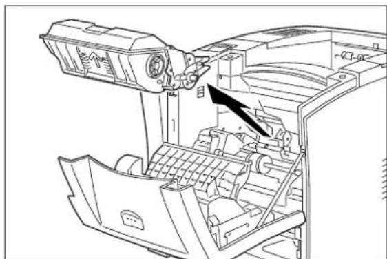
natural_image
Technical line drawing of a mechanical device with internal components and a black arrow indicating a specific part (no text or symbols present)NOTE: To prevent stains, place the toner cartridge on a surface covered with newspaper or other disposable material.
- Lift up on the lever on the left side of the inside of the printer, and fold the cover toward you. Remove any jammed paper.

natural_image
Technical line drawing of a printer internal structure with arrows indicating motion or movement (no text or symbols)- Insert the pegs on the sides of the toner cartridge into the channels on the inside of the printer, and push the cartridge into the printer.

natural_image
Technical line drawing of a mechanical assembly with no visible text or symbols- Close the front cover, pressing on the center of the front cover until it closes securely.

natural_image
Line drawing of a computer printer with an open lid and internal components, showing a hand inserting a cable into the paper (no text or symbols present)Clearing an E4 Jam
If an E4 error code precedes the error message on the first line of the control panel display, paper has jammed somewhere near the paper exit slot. Use the following procedure to clear a paper jam in this location:
- If you are using the paper tray in its extended position, remove it from the printer.

natural_image
Line drawing of a hand inserting a component into a computer drive (no text or symbols)- Squeeze the tabs on the top rear of the printer and pull the rear cover toward you to open it.

- If there is paper jammed in the space behind the rear cover, remove it.
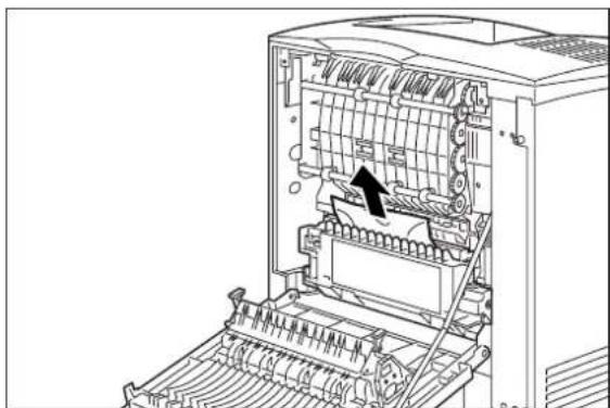
natural_image
Technical line drawing of an open industrial machine with internal components and a black arrow indicating a specific part (no text or symbols present)- If you are using the duplexer, push the green tabs toward the center of the duplexer and pull the duplexer toward you to remove it.


CAUTION: To remove the paper jammed near the fuser, turn the printer off and wait at least 10 minutes to allow the fuser to cool before removing the paper.
- If there is paper jammed around the fuser unit, lift up the fuser unit release levers on the left and right sides of the fuser and remove the jammed paper.

-
Return the fuser release levers to their original position.
-
If you removed the duplexer, insert the duplexer into the printer.
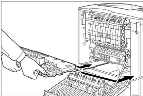
natural_image
Illustration of a hand operating a computer tower with visible internal components and mechanical parts (no text or symbols)- Push the green tabs at the sides of the duplexer out toward the sides of the printer.

natural_image
Technical diagram of a mechanical device showing internal components and directional arrows (no text or symbols)- Close the rear cover.

natural_image
Line drawing of a computer monitor with an arrow indicating the left side of its screen (no text or symbols present)Clearing an E7 Paper Jam
When an E7 error message is shown on the display screen, there is a paper jam in the duplexer. Use the following procedure to clear a duplex paper jam:
- If you are using the paper tray in its extended position, remove the paper tray from the printer.
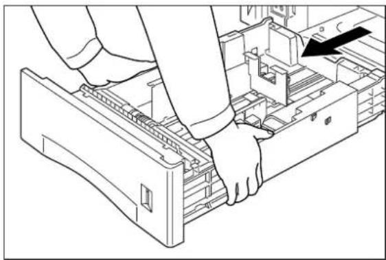
natural_image
Line drawing of a person inserting into a computer drive into a rack (no text or symbols)- Squeeze the tabs on the rear of the printer and pull the rear cover toward you to open it.
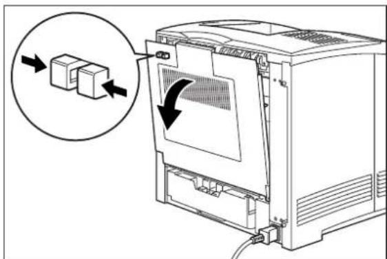
- Remove any jammed paper from the duplex area.
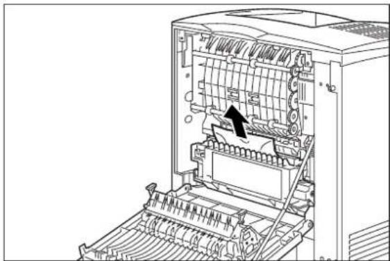
natural_image
Technical line drawing of an open industrial machine with internal components and a black arrow indicating a specific part (no text or symbols present)- Push the green tabs on the sides of the duplexer toward the center of the duplexer, and grasp the recessed areas on the sides of the duplexer and remove it from the printer.

- Push the tabs labelled 1 below out toward the sides of the duplexer, and open the duplexer.
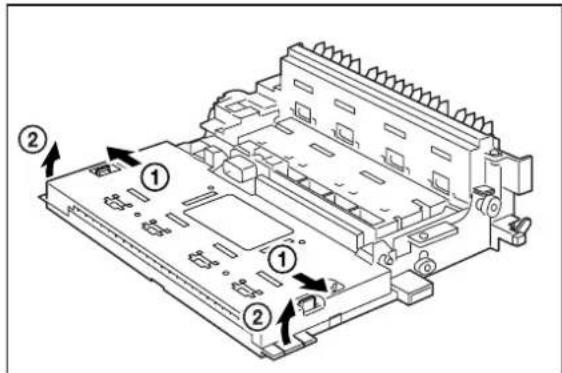
- Remove any jammed paper from inside the duplexer unit.

natural_image
Technical line drawing of a mechanical assembly with no visible text or symbols- Slide the tabs on the left and right sides of the duplexer into the channels inside the printer, and push the duplexer completely into the printer.

natural_image
Illustration of a hand operating a computer tower with visible internal components and mechanical parts (no text or symbols)- Push the green tabs on the sides of the duplexer out toward the sides of the printer to secure the duplexer to the printer.

natural_image
Technical diagram of a mechanical device with internal components and directional arrows indicating movement (no text or symbols present)- Close the rear cover.

natural_image
Line drawing of a computer monitor with an arrow indicating the left side of its screen (no text or symbols present)Clearing an E6 Paper Jam
If an E6 error code precedes the error message on the first line of the control panel display, paper has jammed at the offset catch tray. Use the following procedure to clear a paper jam in this location:
- Pull on the recessed area on the rear of the offset catch tray to open the rear cover.

natural_image
Line drawing of a printer with an arrow indicating a process or operation (no text or symbols present)- Remove any jammed paper from the interior of the offset catch tray.

natural_image
Line drawing of a printer or printer with an arrow indicating a process or operation, no text or symbols present.- Close the rear cover of the offset catch tray.
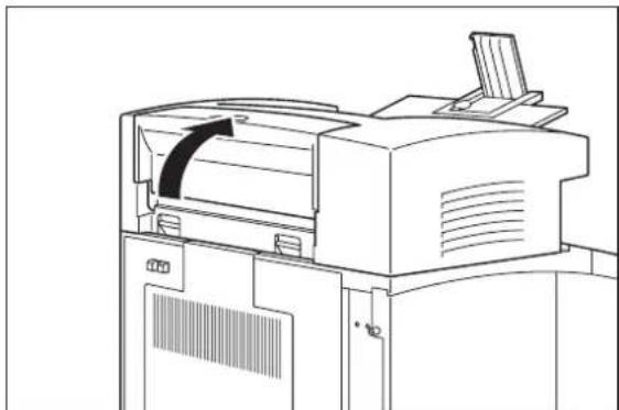
natural_image
Line drawing of a printer with paper feed and ventilation slots (no text or symbols)- Squeeze the latch on the upper part of the rear cover, and pull the cover toward you to open it. If there is paper jammed in the space behind the rear cover, remove it.
NOTE: If the paper tray is in the extended position, remove the tray before opening the rear cover.

natural_image
Diagram of a computer oven with a close-up view showing internal components and directional arrows (no text or symbols)- Close the rear cover.
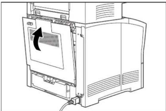
natural_image
Line drawing of a computer oven with an arrow indicating a scroll or rotation (no text or symbols present)Print Image Quality Problems
When functioning correctly, the printer should produce printed paper that is relatively flat and undamaged, containing a fused image of correct intensity—without streaks, smears, spots, or missing areas. If the printed sheets that your printer produces do not meet these qualifications, there is a print image quality problem.
- Minor Print Image Quality Problems can be caused by exhausted or damaged consumables, such as the toner cartridge. These problems area easily corrected by simply replacing the consumable.
■ Major Print Image Quality Problems can be caused by a malfunctioning or broken component. These problems may require you to call a service technician to determine and correct the problem.
This section describes possible quality problems during printing. Go through the list below to find the condition that most resembles the problem, and follow the recommended action. If the trouble persists, turn the printer off and disconnect the power cord from the AC outlet. Then contact your dealer or an authorized service provider.
| Description Possible | Cause Action | |
| Faded print The print media is moist. | Remove the moist media and load new, dry media. | |
 | The toner cartridge is old or damaged.Toner in the toner cartridge is low. | Replace the toner cartridge.Replace the toner cartridge. |
| Black dots The print media is outside the recommended specifications. | Use the recommended print media. | |
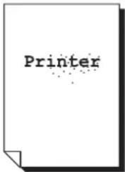 | The toner cartridge is old or damaged. | Replace the toner cartridge. |
Vertical black streaks | The toner cartridge is old or damaged. | Replace the toner cartridge. |
Repetitive defects  | The paper path is dirty.The toner cartridge is old or damaged. | Print out several blank sheets.Replace the toner cartridge. |
Character voids  | print media is outside the recommended specifications.The toner cartridge is old or damaged. | Use the recommended print media.Replace the toner cartridge. |
Toner smears when rubbed | The print media is moist.The print media is outside the recommended specifications.The front cover not fully closed. | Remove the moist media and load new, dry media.Use the recommended print media.Close the front cover properly. |
Black page The toner  | cartridge is old or damaged.The high-voltage power supply may be defective. | Replace the toner cartridge.Contact your dealer or an authorized service provider. |
Blank page The sealing tape of the toner cartridge is not pulled out.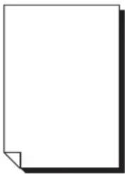 | The printer feeds two or more sheets at a time.The toner cartridge is old or damaged.The toner in the toner cartridge is low.The high-voltage power supply may be defective. | Pull out the sealing tape.Avoid adding paper to a nearly full stack.Replace the toner cartridge.Replace the toner cartridge.Contact your dealer or an authorized service provider. |
Partial blanks The print media is moist. | The print media is outside the recommended specifications.The sealing tape of the toner cartridge is not fully pulled out. | Remove the moist media and load new, dry media.Use the recommended print media.Replace the toner cartridge. |
Creased paper The print media is outside the recommended specifications. | Use the recommended print media.Remove the moist media and load new, dry media. | |
Plotted print The print media is outside the recommended specifications.  | The print media is moist. The toner cartridge is old or damaged. | Use the recommended print media. Remove the moist media and load new, dry media. Replace the toner cartridge. |
Vertical blanks The toner cartridge is not installed correctly.  | The toner cartridge is old or damaged. | Remove the toner cartridge and reinstall it. Replace the toner cartridge. |
Blurred print The toner cartridge is old or damaged. 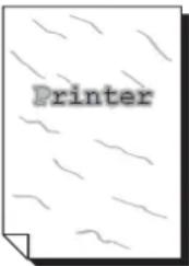 | Replace the toner cartridge. | |
Bold print appears shaded  | The toner cartridge is old or damaged. | Replace the toner cartridge. |
Other Print Image Quality Problems
The following characteristics define this print image problem:
- The finished print has a problem that is not identified by any of the other procedures in this manual.
■ The control panel does not display an error code.
The following procedure guides you through multiple actions that may solve this print image quality problem. Proceed one step at a time until the problem is solved—you may not need to complete the entire procedure. If one of the steps in this procedure corrects the problem but the identical problem returns in less than 50 prints, call for service.
- Replace all of the paper in the paper trays with newly opened paper.
The paper in the trays may be damp or damaged, resulting in poor image quality. New paper may correct the problem.
- Replace the toner cartridge with a new one.
The toner cartridge may have reached end of life or is damaged.
- Disconnect then reconnect the interface cable that runs between the printer and the host computer.
There may be a bad connection between the printer and the computer. Reconnecting both ends should reestablish a good electrical connection. If you have another interface cable available, substitute that cable for the one currently connecting the printer and the computer.
- Reinstall the print driver software.
The print driver software that is running on the host computer may be damaged. Reinstalling the software is an easy and inexpensive way to isolate or eliminate the source of the problem. Refer to the DRIVERS folder on the electronic library CD-ROM for detailed instructions on installing the driver.
- Call your service technician.
This image quality problem may be caused by a malfunctioning or broken component that requires service.
Miscellaneous Problems
Some printer problems may not generate error codes or produce observable print image defects. These miscellaneous problems may effect only the printer or they may effect things outside of the printer, such as the room lights or a nearby radio receiver.
This section contains detailed procedures for correcting the following problems:
■ Printer is Inoperative
■ Printer Operates Erratically
■ Printer Makes Unusual Noises
■ Room Lights Dim or Flicker When Printer Starts
■ Printer Interferes with Nearby Radio or Television Reception
Printer is Inoperative
The following characteristics define this type of problem:
■ The printer appears to have no power.
■ The control panel does not light up or display characters.
■ The printer motors do not run and the printer does not warm up.
■ The control panel does not display an error code.
The following procedure guides you through multiple actions that may solve this print image quality problem. Proceed one step at a time until the problem is solved—you may not need to complete the entire procedure. If one of the steps in this procedure corrects the problem but the identical problem returns in less than 50 prints, call for service.
- Make sure that you push the [I] on the main power switch to turn on the printer.
- Check to make sure the AC power cord is firmly plugged into the AC wall outlet and that the other end of the AC power cord is firmly plugged into the printer.
Sometimes the AC power cord is only partially plugged in and is not making good electrical contact. If the AC power cord keeps working loose you might consider moving the printer to a safer location. If the AC wall outlet is broken, allowing the power cord to easily fall out, replace the outlet.
- Test for voltage present by plugging an AC electrical device, such as a lamp, into the AC wall outlet. If the lamp does not light, inspect the building circuit breakers or check for a broken AC wall outlet.
A circuit breaker trips because there was an overload on the line. A tripped breaker may indicate that you have too many AC devices working off the same line or that you have faulty building wiring. If the breaker is not tripped, but the lamp doesn't light when plugged into the outlet, replace the outlet or have an electrician check the line.
- Turn the printer off and wait 20 minutes, then turn the printer on.
Thermal sensors may have shut down the printer. Waiting 20 minutes for the printer to reset may return the printer to normal operation. A thermal shutdown may indicate there is a more serious problem with the printer. If the problem reoccurs, call for service.
- Call your service technician.
This problem may be caused by a malfunctioning or broken component that requires service.
Printer Operates Erratically
The following characteristics define this type of problem:
■ The printer does not function correctly.
■ The printer may go into frequent warm-up.
■ The control panel may display garbled characters.
■ The printer may lose power or stop printing for no apparent reason.
■ The control panel does not display an error code.
The following procedure guides you through multiple actions that may solve this print image quality problem. Proceed one step at a time until the problem is solved—you may not need to complete the entire procedure. If one of the steps in this procedure corrects the problem but the identical problem returns in less than 50 prints, call for service.
- Check to make sure the AC power cord is firmly connected to the AC wall outlet and that the other end of the AC power cord is firmly connected to the printer.
A loose or partially connected AC power cord may cause erratic operation. If the AC power cord is repeatedly loose or disconnected, you may consider moving the printer to a safer location. If the AC wall outlet is broken, allowing the power cord to easily fall out, replace the outlet.
- Check to make sure the computer interface cable is firmly connected to the printer and that the other end of the cable is firmly connected to the computer.
There may be a bad connection between the printer and the computer. Reconnecting both ends should reestablish a more reliable electrical connection. If you have another interface cable available, substitute the new cable for the one currently connecting the printer and computer.
- Open and then firmly close all printer doors and covers.
Interlock switches monitor the position of printer doors and covers for safety reasons. When a door is closed, the interlock switch is activated and the printer can operate. When a door is open, the interlock switch is not activated and the printer cannot operate. If a door is not firmly closed, the interlock switch can bounce between being activated and being not activated—confusing the system and causing erratic printer operation.
- Reinstall the print driver software.
The print driver software that is running on the host computer may be damaged. Reinstalling the software is an easy and inexpensive way to isolate or eliminate the problem. Refer to the DRIVERS folder on the Electronic Library CD-ROM for detailed instructions on installing the driver.
- Unplug the AC power cord from the AC wall outlet. Plug a 100 watt lamp into the AC wall outlet and watch the lamp for 30 minutes. If the lamp flickers noticeably or dims then brightens, you should replace the outlet or have an electrician check the line.
Voltage surges or drops at the AC wall outlet can cause sensitive printer components to function erratically. In some instances wide voltage swings can seriously damage the printer.
- Call your service technician.
This problem may be caused by a malfunctioning or broken component that requires service.
Printer Makes Unusual Noises
The following characteristics define this type of problem:
- The printer makes unusual noises or makes more noises than usual either while idle or while printing.
■ The printer generates printed sheets without a problem.
■ The control panel does not display an error code.
The following procedure guides you through multiple actions that may solve this print image quality problem. Proceed one step at a time until the problem is solved—you may not need to complete the entire procedure. If one of the steps in this procedure corrects the problem but the identical problem returns in less than 50 prints, call for service.
- Turn the printer off and open all of the printer access covers. Inspect the interior of the printer for pieces of paper or obviously broken components that could be causing the noise. Remove any paper that you find. If you see a broken component, call for service.
Broken and dangling components or scraps of paper lodged inside the printer may be brushing against moving parts and causing the noise.
- Inspect the fan outlets for broken grills or objects stuck in the fans. Remove any objects from the fan grill. If you see a broken grill or cover, call for service.
An object or part of a broken fan grill may be bushing against the fan and causing the noise. A broken fan grill is a potential safety hazard and should be replaced.
- Call your service technician.
This problem may be caused by a malfunctioning or broken component that requires service.
Room Lights Dim or Flicker When Printer Starts
The following characteristics define this type of problem:
- Nearby lights dim slightly or flicker when you first turn on the printer or when the printer begins printing.
■ The lights remain normal when the printer is not on.
■ The printer generates printed sheets without a problem.
■ The control panel does not display an error code.
The following procedure guides you through multiple actions that may solve this print image quality problem. Proceed one step at a time until the problem is solved—you may not need to complete the entire procedure. If one of the steps in this procedure corrects the problem but the identical problem returns in less than 50 prints, call for service.
- Unplug all devices that are plugged into the same AC wall outlet as the printer.
During warm-up and at the start of each print run, the printer normally draws a large amount of current. If other devices are running off of the same AC circuit, the accumulative current draw may result in nearby lights momentarily dimming.
- Have an electrician check your building wiring.
There may be a problem with the AC outlet or the AC wiring in the building that needs the attention of a licensed electrician.
- Call your service technician.
This problem may be caused by a malfunctioning or broken component that requires service.
Printer Interferes with Nearby Radio or Television Reception
The following characteristics define this type of problem:
- When the printer begins printing, it causes audio noise in nearby radios or interferes with the picture in nearby televisions.
■ The printer generates printed sheets without a problem.
■ The control panel does not display an error code.
The following procedure guides you through multiple actions that may solve this print image quality problem. Proceed one step at a time until the problem is solved—you may not need to complete the entire procedure. If one of the steps in this procedure corrects the problem but the identical problem returns in less than 50 prints, call for service.
- If the radio/television is plugged into the same AC wall outlet as the printer, plug either the printer or the radio/television into another AC outlet.
Electrical noise may be transmitted through the AC line. You can reduce the noise to the radio/television by using a dedicated AC wall outlet for the printer.
- Move the radio/television away from the printer.
Your printer complies with the FCC rules regarding radio/television interference caused by digital devices. This printer generates, uses, and may radiate low levels of radio frequency energy that could interfere with radio and television reception in some installations. Increasing the distance between the printer and the radio/television is a very effective method for reducing minor interference.
- Identify the building circuit breaker that controls the AC outlet to your printer. Identify all of the AC outlets that are controlled by that circuit breaker. Unplug all devices from the AC outlets that are controlled by that circuit breaker, except for the printer.
Electrical noise may be transmitted through the AC line. In difficult interference cases you may have to dedicate an entire AC line to the printer.
- Call your service technician.
This problem may be caused by a malfunctioning or broken component that requires service.
Warning Messages and Error Messages
The control panel display shows a warning message or error message when there is a problem with the printer. Some messages indicate routine status conditions such as an empty paper tray, while others indicate that a sheet of paper has jammed in a specific area of the printer. Some messages indicate more serious printer problems that may require the help of a service technician.
Warning messages use only the second line of the display and indicate conditions that do not prevent the printer from operating. For example, if Tray 1 is out of paper but the printer is currently drawing paper from Tray 2, a warning message will appear on the second line of the display indicating that Tray 1 is out of paper—but the printer will continue to operate, drawing paper from Tray 2.
Error messages use both lines of the display and indicate conditions that prevent the printer from operating. The first line of an error message contains the error code and type of error, while the second line of the display contains information about the action required to recover from the error.
When the control panel displays a warning or error message, refer to the following tables and complete the actions recommended for the specific message that is shown.
Warning Messages
The following table lists warning messages, possible causes, and the actions required to correct each cause.
| Warning Message Line 2 of display | Possible Cause Action | |
| Paper Out Tray 1 There is no paper in Tray 1. Add paper to the tray. | ||
| Paper Out Tray 2 There is no paper in Tray 2. Add paper to the tray. | ||
| Paper Out Tray 3 There is no paper in tray 3. Add paper to the tray. | ||
| Output Tray Full The output tray is full. Remove paper from the tray. | ||
| Offset Tray Full The offset output tray is full. Remove paper from the tray. | ||
| Toner Low The toner is low. Replace the toner cartridge soon. | ||
| Maintenance Req Maintenance is required. Call service. | ||
Error Messages
The table below lists error messages, the possible causes of each error, and the actions required to recover from each error.
| Error Message Line 1 | Error Message Line 2 | Possible Cause Action | |
| E2 JAM MISFEED E3 JAM FUSER E4 EXIT JAM E6 JAM OFF. TRAY E7 JAM DUPLEX | Remove Paper There is a paper jam inside the printer. | Remove the jammed paper from the indicated location. See the “Paper Jams” on page 5-4 for information about removing paper jams. | |
| E5 COVER OPEN Close | Top Cover The top cover is open. Close the top or rear cover. | ||
| E5 COVER OPEN Close | Rear Cover | The rear cover is open. Close the offset tray cover. | |
| J3 TONER CART. Install | /Reset The toner cartridge is not installed, or an incorrect cartridge is installed. | Install the correct toner cartridge according to the specifications. See “Replacing the Toner Cartridge” on page 4-3. | |
| TRAY 1 MISSING Insert | Tray Tray 1 is not in the printer. | Insert the tray. | |
| TRAY 2 MISSING Insert | Tray Tray 2 is not in the optional feeder. | Insert the tray. | |
| TRAY 3 MISSING Insert | Tray Tray 3 is not in the optional feeder. | Insert the tray. | |
| LOAD PAPER TRAY1 | Paper Size/ Paper Type | Tray 1 is empty. | Load paper into the tray. |
| LOAD PAPER TRAY2 | Paper Size/ Paper Type | Tray 2 is empty. | Load paper into the tray. |
| LOAD PAPER TRAY3 | Paper Size/ Paper Type | Tray 3 is empty. | Load paper into the tray. |
| LOAD PAPER FRONT | Paper Size/ Paper Type | The front tray is empty. | Load paper into the tray. |
| PAPER SIZE ERROR Paper Size/ Press Start | The paper size is not supported by the printer. | Check paper size specifications and load paper that meets specifications. | |
| OUTPUT TRAY FULL | Remove Paper | The output tray is full. | Remove paper from the tray. |
| OFFSET TRAY FULL Remove Paper The offset output tray is full. | Remove paper from the tray. | ||
| Error Message Line 1 | Error Message Line 2 | Possible Cause | Action |
| U2 ROS FAILURE Call Service The ROS has failed. Turn the printer off, then turn it on. If the problem reoccurs, contact an authorized service provider. | |||
| U4 FUSER FAILURE Call Service The fuser has failed. | |||
| ENV UNIT FAILURE Chk Feeder The envelope unit was removed or has failed. | |||
| OFFSET TRAY FAIL Call Service The offset tray was removed or has failed. | |||
| OPTION TRAY FAIL Call Service. One of the optional trays has failed. | |||
| DUPLEX FAILURE Call Service The duplexer was removed or has failed. | |||
| MAIN MOTOR FAIL Call Service The main motor has failed. | |||
| ENGINE NV FAIL Call Service The engine has failed. | |||
| FAN FAILURE Call Service The fan has failed. | |||
| MAINTENANCE REQ Press Start The printer needs maintenance. | Press the START button. | ||
Chapter 6
Using the Duplexer
In this Chapter . . .
■ "About this Chapter" on page 6-2
■ "About the Duplexer" on page 6-2
■ "Installing the Duplexer" on page 6-2
■ "Testing the Duplexer" on page 6-4
■ "Solving Duplexer Problems" on page 6-6
■ "Removing the Duplexer" on page 6-13
About this Chapter
This chapter provides all of the information necessary to install, use, and maintain the duplexer.
About the Duplexer
The duplexer is a customer-installed optional device that enables automatic printing on both sides of a sheet of paper. The duplexer is designed to be mounted inside the printer, just below the exit transport in the paper path. The duplexer drives a single-sided print partially out of the exit transport, then reverses the direction and pulls the printed page back into the printer to print the second side. The printer can image two pages at a time, therefore the duplex unit will process two pages (sides 1 and 3) then refeed these pages for sides 2 and 4.
Major Components of the Duplexer
The following figure shows the major components of the duplexer.
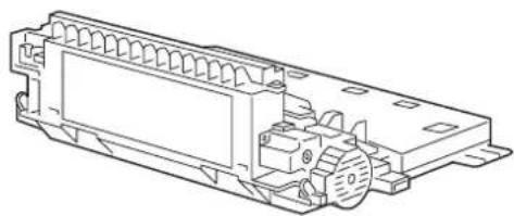
natural_image
Technical line drawing of a mechanical housing or enclosure with internal components (no text or symbols)Installing the Duplexer
Before you begin the installation procedure, remove the duplexer from its packaging and remove any shipping tape or cardboard inserts. Verify that you have received the following items:.


natural_image
Technical line drawing of an electronic component with no visible text or symbolsDuplexer Installation Sheet Duplexer
Figure 6-1: Contents of Duplexer Shipping Box.
Use the following procedure to install the duplexer:
- Turn the printer off and remove the AC plug from the AC wall outlet.

natural_image
Line drawing of a computer with two views: one showing a close-up of a device and another showing a close-up of a power strip (no text or symbols present)- If you are using the paper tray in its extended position, remove the paper tray from the printer.

natural_image
Line drawing of a person inserting a device into a rack (no text or symbols visible)- Squeeze the tabs on the left rear of the printer and pull the rear cover toward you to open it.

natural_image
Line drawing of a computer oven with a magnified inset showing a component being inserted (no text or symbols present)- Slide the tabs on the left and right sides of the duplexer into the channels inside the printer, and push the duplexer completely into the printer.

natural_image
Illustration of a hand operating a computer tower with visible internal components and mechanical parts (no text or symbols)- Push the green tabs on the sides of the duplexer out toward the sides of the printer to secure the duplexer to the printer.

natural_image
Technical diagram of an industrial machine with internal components and directional arrows indicating movement (no text or symbols present)- Close the rear cover.
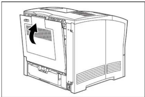
natural_image
Line drawing of a computer case with an arrow indicating a scroll or rotation around the screen (no text or symbols present)Testing the Duplexer
After installing the duplexer, use the following procedure to make sure it transports paper correctly:
-
Turn the printer on by pressing the [I] on the power switch on the right side of the printer.
-
Once the printer has warmed up and displays the "Ready" message on the control panel display, use any software application to print a few duplexed sheets.
- If the duplexer does not transport paper or if the control panel shows an error message, refer to "Solving Duplexer Problems" on page 6-6.
Solving Duplexer Problems
When there is a problem with the duplexer, the printer control panel displays an error code and error message. Most duplexer error codes indicate routine status conditions such as a paper tray running out of paper or a paper jam in a specific area of the duplexer. Some error codes indicate much more serious problems that may require the help of a service technician.
- If the duplexer is inoperative after installation, refer to “Installation Problems” on page 6-6 and complete the recommended procedure.
- If the printer control panel displays an error message or an error code, refer to “Interpreting Duplexer Error Codes” below.
- If you have a duplexer problem but the printer control panel does not display an error message or error code, refer to “Correcting Miscellaneous Duplexer Problems” on page 6-10 and follow the directions for correcting that problem.
Interpreting Duplexer Error Codes
The printer control panel displays error messages when there is a problem with the printer or any of the optional paper-handling components. The following table lists all of the error messages associated with the duplexer, the possible cause of the error, and the action to take to correct the problem. If the control panel shows an error message that concerns another part of the printer, refer to Chapter 5: Troubleshooting for a complete list of all warning and error messages.
| Error Message Line 1 | Error Message Line 2 | Possible Cause Action | |
| E7 JAM DUPLEX Remove paper There is a paper jam in the duplexer. | Remove the jammed paper from the duplexer.See “Clearing Duplex Paper Jams” on page 6-7. | ||
| DUPLEX FAILURE | Call Service | The duplexer has failed. | Turn the printer off, then turn it on. If the problem reoccurs, contact an authorized service provider. |
Installation Problems
Simple oversights during installation may cause problems when you first use the duplexer. If the duplexer is inoperative after you have installed it, use the following procedure to check several possible causes.
- Turn the printer off by pressing the [O] on the power switch on the right side of the printer.
- Make sure that the duplexer is firmly seated inside the printer.
- If the duplexer is firmly seated in the printer, but the duplexer is still inoperative, return to "Installing the Duplexer" on page 6-2 and carefully repeat all of the installation steps.
- If the duplexer is still inoperative after reinstallation, remove it from the printer so you can run tests on the printer without the duplexer affecting the tests.
- Print a few sheets of text or images to make sure the printer is still operational.
If the printer is operational when the duplexer is removed, contact either your sales representative or a service provider and report your problem.
If the printer is not operational after you have removed the duplexer, refer to Chapter 5: Troubleshooting. After correcting the printer problem, return to "Installing the Duplexer" on page 6-2 and reinstall the duplexer.
Clearing Duplex Paper Jams
When an E7 error message is shown on the display screen, there is a paper jam in the duplexer. Use the following procedure to clear a duplex paper jam:
- If you are using the paper tray in its extended position, remove the paper tray from the printer.

natural_image
Line drawing of a person inserting or adjusting a device into a rack (no text or symbols visible)- Squeeze the tabs on the rear of the printer and pull the rear cover toward you to open it.

- Remove any jammed paper from the duplex area.
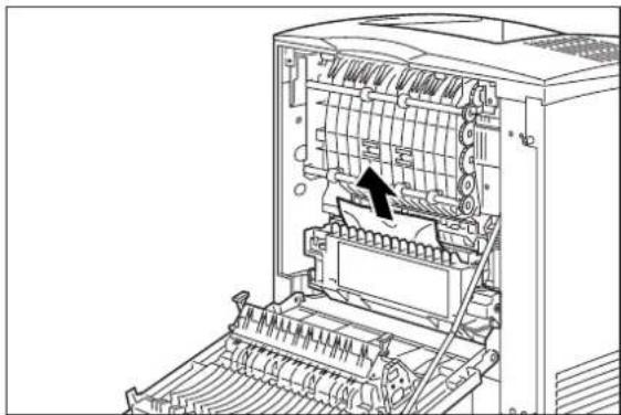
natural_image
Technical line drawing of an open industrial machine with internal components and a black arrow indicating a specific part (no text or symbols present)- Push the green tabs on the sides of the duplexer toward the center of the duplexer, and grasp the recessed areas on the sides of the duplexer and remove it from the printer.
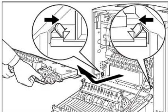
- Push the tabs labelled 1 below out toward the sides of the duplexer, and open the duplexer.

- Remove any jammed paper from inside the duplexer unit.

natural_image
Technical line drawing of a mechanical assembly with no visible text or symbols- Slide the tabs on the left and right sides of the duplexer into the channels inside the printer, and push the duplexer completely into the printer.
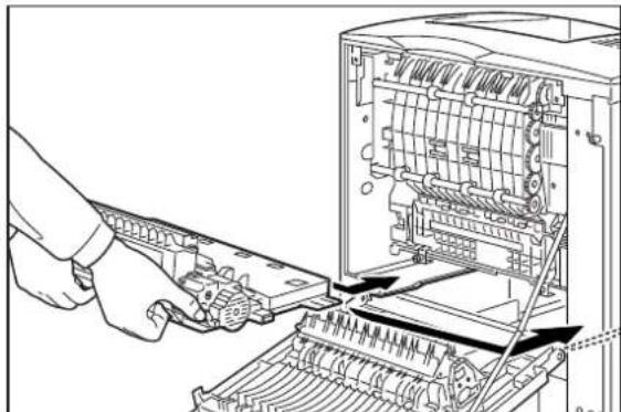
natural_image
Illustration of a hand operating a computer tower with visible internal components and mechanical parts (no text or symbols)- Push the green tabs on the sides of the duplexer out toward the sides of the printer to secure the duplexer to the printer.

natural_image
Technical diagram of a mechanical device with internal components and directional arrows indicating movement (no text or symbols present)- Close the rear cover.
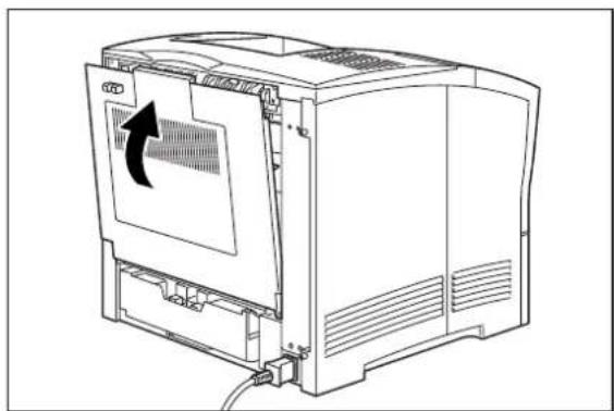
natural_image
Line drawing of a computer monitor with an arrow indicating the left side of its screen (no text or symbols present)Correcting Miscellaneous Duplexer Problems
Some duplexer problems may not cause an error message and may not interfere with the operation of the printer. If you are experiencing one of the problems listed below and there is no error message shown on the control panel display, refer to the procedures in the following sections to check the possible causes of the specific problem.
■ Inoperative duplexer
- Erratic operation
■ Unusual noise
Inoperative Duplexer
The following characteristics define this duplexer problem:
■ The duplexer appears to be inoperative.
- When attempting to print duplexed sheets, the duplexer does not respond and does not feed paper.
■ The control panel does not display an error code.
The following procedure guides you through multiple actions that may solve this duplexer problem. Proceed one step at a time until the problem is solved—you may not need to complete the entire procedure. If one of the steps in this procedure corrects the problem but the identical problem returns in less than 50 prints, call for service.
- Open and then firmly close all of the printer doors and covers.
Interlock switches monitor the position of printer doors and covers. When a door is closed, the interlock switch is activated and the duplexer can operate. When a door is open, the interlock switch is not activated and the duplexer cannot operate. If a door is not firmly closed, the interlock switch may not be fully activated—resulting in an inoperative duplexer.
- Test the printer by printing single-sided sheets from the main tray.
If you cannot print a sheet of paper from the main tray and the printer does not display an error code, go to "Inoperative Printer" on page 5-3. If you can print a sheet of paper from the main tray, proceed to the next step.
- Open the rear cover of the printer. Remove and reinstall the duplexer.
If the connection between the duplexer and the printer is not intact, the duplexer will not receive power or logic commands, resulting in an inoperative duplexer
-
Examine the printer driver settings to make sure the duplexer is available as an installed option.
-
If the duplexer is correctly set as an installed option, reload the printer driver software.
The printer driver software running on the host computer may be damaged. Reinstalling the software is an easy and inexpensive way to isolate or eliminate the problem. Refer to the DRIVERS folder on the Electronic Library CD-ROM for detailed instructions on installing the driver.
- Call your service technician.
This problem may be caused by a malfunctioning or broken component that requires service.
Duplexer Operates Erratically
The following characteristics define this duplexer problem:
■ The duplexer does not function correctly.
■ The control panel does not display an error code.
The following procedure guides you through multiple actions that may solve this duplexer problem. Proceed one step at a time until the problem is solved—you may not need to complete the entire procedure. If one of the steps in this procedure corrects the problem but the identical problem returns in less than 50 prints, call for service.
- Open the rear cover of the printer. Remove and reinstall the duplexer.
If the connection between the duplexer and the printer is not intact, the duplexer will not receive power or logic commands, resulting in an inoperative duplexer.
- Test the printer by allowing it to run for a few days without the duplexer installed.
If the printer operates erratically when the duplexer is not installed, refer to “Printer Operates Erratically” on page 5-23.
If the printer does not operate erratically when the duplexer is not installed, reinstall the duplexer and proceed to the next step.
- Open and then firmly close all of the doors and covers.
Interlock switches monitor the position of printer doors and covers. When a door is closed, the interlock switch is activated and the duplexer can operate. When a door is open, the interlock switch is not activated and the duplexer cannot operate. If a door is not firmly closed, the interlock switch can bounce between being activated and being not activated - confusing the system and causing erratic operation.
- Reinstall the printer driver software.
The printer driver software running on the host computer may be damaged. Reinstalling the software is an easy and inexpensive way to isolate or eliminate the problem. Refer to the DRIVERS folder on the Electronic Library CD-ROM for detailed instructions on installing the drivers.
- Call your service technician.
This problem may be caused by a malfunctioning or broken component that requires service.
Duplex Makes Unusual Noises
The following characteristics define this duplexer problem:
- The duplexer makes unusual noises or makes more noise than usual either while idle or while printing.
■ The duplexer feeds paper without a problem.
■ The control panel does not display an error code.
The following procedure guides you through multiple actions that may solve this duplexer problem. Proceed one step at a time until the problem is solved—you may not need to complete the entire procedure. If one of the steps in this procedure corrects the problem but the identical problem returns in less than 50 prints, call for service.
- Open the rear cover of the printer and inspect the inside of the duplexer for jammed paper or obviously broken components.
Broken components or scraps of paper lodged inside the duplexer may be brushing against moving parts and causing the noise.
- Call your service technician.
This problem may be caused by a malfunctioning or broken component that requires service.
Removing the Duplexer
Use the following procedure to remove the duplexer:
- Turn off the printer and disconnect the AC power cord from the AC wall outlet..

natural_image
Line drawing of a computer with two views: one showing a close-up of a switch, the other showing a hand inserting a control panel (no text or symbols present)- If you are using the paper tray in its extended position, remove the paper tray from the printer.

natural_image
Line drawing of a person inserting a device into a rack, with an arrow pointing to the component (no text or symbols present)- Squeeze the tabs on the top left of the rear cover, and pull the cover to open it.

natural_image
Line drawing of a computer with an open lid and internal panel, showing a close-up of a device's front panel (no text or symbols present)- Pull the duplex unit toward you while sliding the left and right tabs inward, then grasp the recessed areas on the sides of the duplex unit and remove it from the printer.

- Close the rear cover.
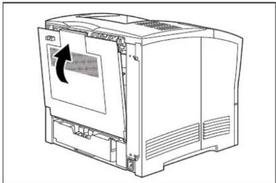
natural_image
Line drawing of a computer tower with an arrow indicating the left side of the cover (no text or symbols present)Chapter 7
Using the 550 Sheet Feeder
In this Chapter . . .
■ "About the 550 Sheet Feeder" on page 7-2
■ "Installing the 550 Sheet Paper Feeders" on page 7-3
■ "Testing the 550 Sheet Feeder" on page 7-11
■ "Selecting Print Media" on page 7-11
■ "Loading Print Media" on page 7-12
■ "Solving 550 Sheet Feeder Problems" on page 7-16
■ "Maintaining the 550 Sheet Feeder" on page 7-21
■ "Moving the 550 Sheet Feeder" on page 7-29
About this Chapter
This chapter provides all of the information necessary to install, use, and maintain the 550 sheet paper feeder option, including procedures for cleaning the feeder and removing paper jams.
About the 550 Sheet Feeder
The 550 sheet feeder is an optional single tray paper feeder that attaches under the printer. The feeder holds a universal paper tray that accommodates a variety of print media and holds a maximum of 550 sheets of standard weight paper. The printer supplies all of the operating power that is needed by the feeder, and motors and circuit boards internal to the feeder provide the feeder with drive and operational logic.
At the start of a print run the feeder motor switches on and begins to feed a sheet of paper out of a selected tray. Rubber rollers drive the sheet out of the tray, through the feeder, and into the printer. Sensors monitor the progress of the paper as it travels through the feeder.
The 550 sheet feeder can be installed in the following configurations:
■ Printer and one 550 sheet feeder
■ Printer and two 550 sheet feeders

natural_image
Simple line drawing of a rectangular container with a side panel and internal structure (no text or symbols)
natural_image
Line drawing of a three-tiered storage unit or shelf with no text or symbolsMajor Components of the 550 Sheet Feeder
The following illustration shows the major components of the 550 sheet feeder:

Installing the 550 Sheet Paper Feeders
Before installing the paper feeder(s), verify that you have received the following items in the paper feeder shipping box:

natural_image
Technical line drawing of a computer case with internal components and mounting holes (no text or labels)550 Sheet Paper Feeder

natural_image
Technical line drawing of a computer chassis frame (no text or symbols)Universal Paper Tray
3 Thumbscrews

Installation Sheet
Installing One Paper Feeder
Use the following procedure to install one paper feeder:

WARNING: Before installing any options, turn the printer off by pressing [O] on the power switch on the right side of the unit and disconnect the power cord from the AC outlet. These precautions are necessary to avoid the risk of electric shock.
- Remove the 550 sheet paper feeder from its packaging and remove any cardboard inserts and packing tape. Locate and set aside the small plastic bag containing three thumbscrews.
- Place the paper feeder on a sturdy, level surface.

natural_image
Technical line drawing of a computer chassis with visible internal components and mounting holes (no text or labels)NOTE: Do not move the printer once the paper feeder is installed.
- Turn the printer off by pressing [O] on the power switch on the left front of the unit.

natural_image
Line drawing of a computer monitor with a magnified inset showing the front panel (no text or symbols)NOTE: Installing the paper feeder while the printer is on may damage the printer or paper feeder.
- Disconnect the power cord from the AC outlet and from the printer.
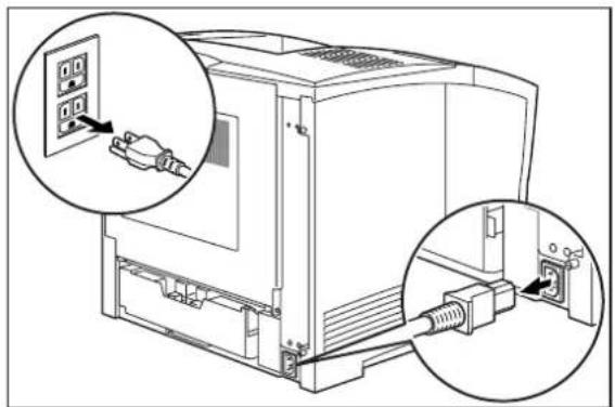
natural_image
Technical diagram of an electronic device showing two connected cables with a plug inserted into the cable (no text or labels present)- Close the front tray, and remove any printed sheets from the paper output tray.

natural_image
Line drawing of a computer printer with ventilation slots and ports (no text or symbols)- Remove the main paper tray from the printer.

natural_image
Line drawing of a computer monitor with an open door and internal casing (no text or symbols)- Align the holes on the bottom of the printer with the pegs on the paper feeder, and lower the printer onto the paper feeder.

natural_image
Technical diagram of a computer tower case with internal components and mounting points (no text or symbols)NOTE: Be sure to lower the printer gently. Components inside the printer may be damaged by lowering the printer quickly.
- Insert the three thumbscrews supplied with the paper feeder into the holes on the base of the printer, and turn them until tight.

natural_image
Diagram of a computer tower with a central screw and connecting lines, showing internal components without any text or symbols.- Load paper into the paper tray.

natural_image
Technical line drawing of a mechanical device casing with internal compartments and mounting brackets (no text or symbols)- Insert the feeder paper tray and the main paper tray all the way into the paper feeder, making sure each is properly seated inside the printer.

natural_image
Line drawing of a computer tower with an open drawer and two arrows indicating file direction (no text or symbols)- Insert the plug of the power cord into the AC outlet, and turn the printer on by pressing [I] on the power switch on the left front of the printer.
NOTE: If an error message appears on the control panel display, see Chapter 5: Troubleshooting.
Installing Two Paper Feeders
Use the following procedure to install two paper feeders:
-
Remove the paper feeders from their packaging and remove any packing tape or cardboard inserts. Set aside the small plastic bags, each containing three thumbscrews.
-
Place one paper feeder on a sturdy, level surface.

natural_image
Technical line drawing of a mechanical device casing with internal components and mounting brackets (no text or symbols)NOTE: Do not move the printer when the paper feeder is installed.
- Align the three holes on the bottom of the upper feeder with the three stubs on the lower feeder, and place the upper paper feeder on top of the lower paper feeder.
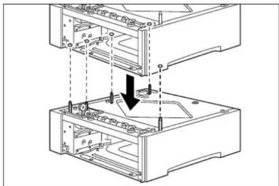
natural_image
Technical line drawing of a computer case with two stacked views and a black arrow indicating a component (no text or symbols present)- Insert the three thumbscrews supplied with the paper feeder into the two holes on the base of the upper paper feeder and turn them until tight.

natural_image
Technical line drawing of a mechanical assembly with two views of a device (no text or symbols)- Turn the printer off by pressing [O] on the power switch on the left front of the printer.
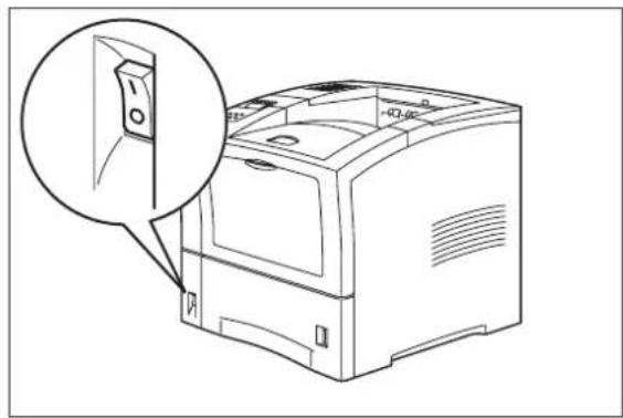
natural_image
Line drawing of a computer monitor with an inset close-up showing a switch (no text or symbols)- Disconnect the power cord from the AC outlet and from the printer.
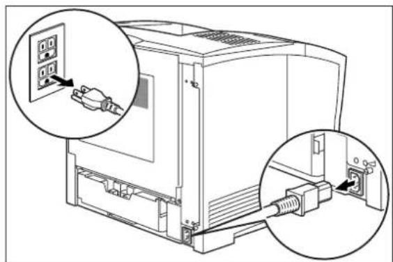
natural_image
Line drawing of a computer setup with two zoomed-in insets showing plug connections (no text or symbols present)NOTE: Installing the paper feeder while the printer is on may damage the printer or the paper feeder.
- Close the front tray, and remove any printed sheets from the output paper tray.

natural_image
Line drawing of a computer printer with front panel and internal casing (no text or symbols)- Remove the main paper tray from the printer.

natural_image
Line drawing of a computer monitor with an open door and internal casing (no text or symbols)- Lift the printer and lower it onto the two stacked paper feeders, aligning the pegs on the upper paper feeder with the holes on the bottom of the printer.
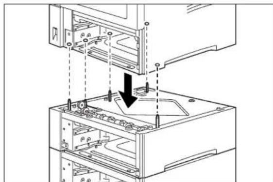
natural_image
Technical line drawing of a computer tower with an open base and internal components, showing no text or symbols.NOTE: Be sure to lower the printer gently. Components inside the printer may be damaged by lowering it quickly.
- Insert the three thumbscrews supplied with the paper feeder into the holes on the base of the printer.

natural_image
Technical line drawing of a mechanical assembly with a central knob and multiple compartments (no text or symbols)- Load paper into the paper trays for both paper feeders.

natural_image
Technical line drawing of a mechanical device casing with internal compartments and mounting brackets (no text or symbols)- Insert the paper trays all the way into the paper feeders, making sure each tray is properly seated.

natural_image
Diagram of a computer tower with multiple drive bays and an open door, showing internal structure without any text or symbols.-
Connect the AC power cord to the printer and the AC wall outlet.
-
Turn the printer on by pressing [I] on the power switch on the left front of the printer.
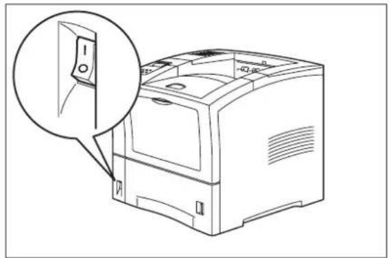
natural_image
Line drawing of a computer monitor with an inset close-up showing a switch (no text or symbols)NOTE: If an error message appears on the control panel display, see the Chapter titled "Error Messages" in the User Manual.
Testing the 550 Sheet Feeder
After installing the 550 sheet paper feeder, use the following test procedure to verify that the feeder is operating correctly.
- Turn the printer on by pressing the [I] on the power switch on the right side of the printer.
- Once the printer has warmed up and displays the "Ready" message on the control panel display, use any software application to print a few sheets from each of the feeder trays.
- If the feeder does not feed paper or if the control panel displays an error message, refer to "Solving 550 Sheet Feeder Problems" on page 7-16.
Selecting Print Media
Your printer can print on a variety of media, including plain paper, labels, transparencies, and envelopes. Always use print media that meet the guidelines for use with this printer. Print media that is not recommended for use with this printer may cause frequent paper jams or poor print quality.
Paper and Print Media To Avoid
Do not use paper or print media that has any of the following characteristics:
■ Does not meet the paper and media size and weight specifications for this printer
- Is not labeled for use with xerographic printers or xerographic copiers
■ Cannot withstand temperatures of up to 310°F/155°C
■ Is in a sealed package that is obviously damaged or wet
■ Is excessively wrinkled, curled, torn, or warped
■ Is folded or creased
■ Has either an extremely slick surface or an extremely textured surface
■ Has an exposed adhesive surface
■ Has paper pieces glued or taped to the media
■ Has staples or paper clips attached
■ Is categorized as thermal paper, coated paper, or carbon paper
- Is an envelope that is embossed, is made of extremely thick paper, or is padded
■ Is an envelope that has metal clasps
■ Is a sheet of labels that has the backing sheet exposed between individual labels
Correct Paper Storage
It is important to store paper correctly prior to placing it in the printer, since improper storage can cause frequent paper jams and poor print quality. Use the following guidelines when storing paper for use in the printer:
■ Store reams of paper on a flat surface, and always store them stacked horizontally.
■ Store reams of paper in an area away from both direct sunlight and high humidity
- Open sealed reams only when you are ready to load the paper into the paper tray, and always close and seal partial reams of paper.
■ Do not stack partial reams of paper
Print Media Weight, Type, and Size
The 550 sheet feeder has paper guides that allow you to accommodate paper with the following dimensions:
• Paper Width: 98.4mm minimum to 215.9mm maximum
• Paper Length: 148.5mm minimum to 355.6mm maximum
The following table defines print media that you can use in the 550 sheet feeder paper tray, and also indicates the feed orientation—long edge feed (LEF) or short edge feed (SEF). If you have concerns about a specific brand or type of media, try samples of the media to determine if the resulting printer performance and print quality meet your expectations.
| Paper Source Weight | Paper Type and | Feed Direction | Paper Sizes Accommodated |
| Universal A4/Letter/ Ledger Paper Tray(main tray and optional 550 sheet A4/Letter/ Ledger paper feeder) | 55-134 kg16 to 24 lbs.60 to 216g/m2 | A4 SEF 297 x 210mm | 11.7 x 8.27 inches |
| Letter SEF 279.4 x 215 | 9mm11 x 8.5 inches | ||
| Legal 13" SEF 330.2 x 215 | 15.9mm13 x 8.5 inches | ||
| Legal 14" SEF 355.6 x 215 | 15.9mm14 x 8.5 inches | ||
| Executive SEF 266.7 x 184.5mm10.5 x 7.26 inches | |||
| B5 SEF | 257 x 182mm10.1 x 7.2 inches | ||
| A5 SEF 210 x 149mm | 8.27 x 5.9 inches | ||
Loading Print Media
Loading the A4/Letter/Legal Paper Tray
The 550-sheet universal paper tray has two width guides that are located on the sides of the tray, and one length guide that is located near the center of the tray. These guides allow you to adjust the size of the area that holds paper.
NOTE: The following procedure shows you how to load paper into the main paper tray. To load paper into the optional 550 sheet paper feeder, simply complete the procedure using the 550 sheet paper tray and feeder rather than the main paper tray.
Use the following procedure to load paper into the 550 sheet A4/letter/legal paper tray:
- Place the paper tray on a level surface.

natural_image
Technical line drawing of a mechanical device casing with internal compartments and mounting brackets (no text or symbols)- Squeeze the length guide, lift it up, and slide it to the rear of the tray.
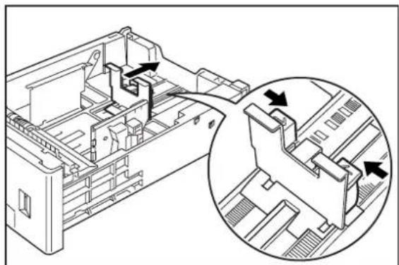
natural_image
Technical line drawing of a vehicle chassis with internal components and a magnified inset showing internal structure (no text or symbols)- If the paper you are using is longer than A4 (297 cm), press the square green button on the bottom of the paper tray to release the rear of the tray, and pull the tray out to extend it.

natural_image
Diagram of hands operating a computer motherboard with arrows indicating process steps (no text or symbols present)7-14 TallyGenicom Intelliprint mL260 User Guide Loading Print Media
-
Squeeze the right width guide, lift it up, and slide the guides to the sides of the tray.
-
Verify that the plate has dropped down into the base of the paper tray. If the tray is locked in the up potision, pull the lever near the front of the tray to release the plate, or push the paper tray all the way into the printer and then remove it.
CAUTION: Do not overload the tray, and make sure the paper stack is beneath the retaining clips on both sides of the tray. Fan paper before placing it in the tray, and place paper in the tray with the side to be printed on facing down.
- Align the edges of the paper and place it in the center of the paper tray with the side to print on facing down.
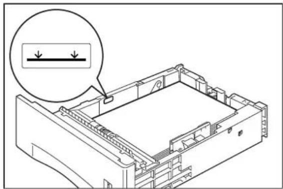
natural_image
Technical line drawing of a mechanical device with a magnified inset showing a dimension line (no text or symbols present)NOTE: To avoid paper jams and other paper transportation problems, make sure the length and width guides are adjusted to match the paper size and are locked firmly into place
- Squeeze the right width guide, lift it up, and adjust the guides to match the paper width.

natural_image
Technical line drawing of a mechanical assembly with an inset close-up showing internal components (no text or symbols)- Squeeze the length guide, lift it up, and adjust the guide to match the paper length.
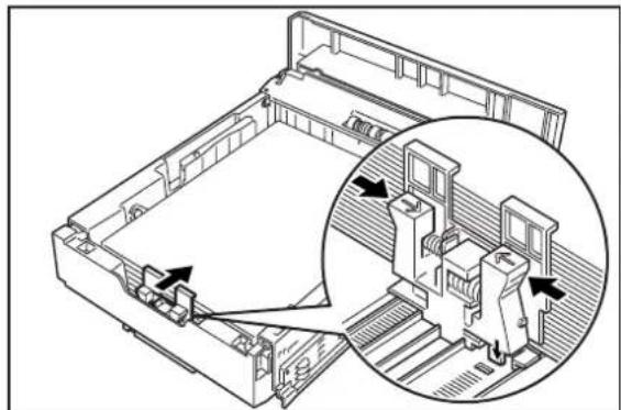
natural_image
Technical line drawing of a mechanical assembly with an inset close-up showing internal components (no text or symbols)- Grasp the paper tray with both hands and insert it into the paper tray well on the printer.

natural_image
Line drawing of hands installing or adjusting a device into a rack (no text or symbols visible)- Push the paper tray completely into the printer, making sure the tray is properly seated..

natural_image
Line drawing of a computer monitor with an open lid and drive base (no text or symbols)- Use the paper level indicator on the front right of the printer to determine when the paper supply is low.

natural_image
Line drawing of a computer case with an inset close-up showing a door mechanism (no text or symbols)Solving 550 Sheet Feeder Problems
When there is a problem with the 550 sheet feeder, the printer control panel displays an error code and error message. Most paper feeder error codes indicate routine status conditions such as a paper tray running out of paper or a paper jam in a specific area of the paper feeder. Some error codes indicate much more serious problems that may require the help of a service technician.
- If the paper feeder is inoperative after installation, refer to “Installation Problems” on page 7-17 and complete the recommended procedure.
- If the printer control panel displays an error message or an error code, refer to “Interpreting Paper Feeder Error Messages” on page 7-17.
If you have a paper feeder problem but the printer control panel does not display an error message or error code, refer to “Correcting Miscellaneous Paper Feeder Problems” on page 7-19 and follow the directions for correcting that problem.
Interpreting Paper Feeder Error Messages
The printer control panel displays error messages when there is a problem with the printer or any of the optional paper-handling components. The following table lists all of the error messages associated with the 550 sheet paper feeder, the possible cause of the error, and the action to take to correct the problem. If the control panel shows an error message that concerns another part of the printer, refer to Chapter 5: Troubleshooting for a complete list of all warning and error messages.
| Error or Warning Message Line 1 | Error or Warning Message Line 2 | Possible Cause Action | |
| (Warning message, printer continues operating and line 1 shows printer status.) | Paper Out Tray 2 (applies to first paper feeder if installed) | There is no paper in tray 2. | Add paper to the tray. |
| Paper Out Tray 3 (applies to second paper feeder if installed) | There is no paper in tray 3. | Add paper to the tray. | |
| TRAY 2 MISSING (applies to first paper feeder if installed) | Insert Tray Tray 2 is not installed. Install the tray. | ||
| TRAY 3 MISSING (applies to second paper feeder if installed) | Insert Tray Tray 3 is not installed. Install the tray. | ||
| E2-1 JAM MISFEED Remove paper There is a misfeed jam near the source paper tray. | Remove the jammed paper from the source tray. | ||
| LOAD PAPER TRAY2 (applies to first paper feeder if installed) | Paper Size/ Paper Type | Tray 2 is empty. Load paper into the tray. | |
| LOAD PAPER TRAY3 (applies to second paper feeder if installed) | Paper Size/ Paper Type | Tray 3 is empty. Load paper into the tray. | |
| OPTION TRAY FAIL Call Service | Turn printer off then on. If problem persists, call your service provider. | ||
Installation Problems
Simple oversights during installation may cause problems when you first use the paper feeder. If the paper feeder is inoperative after you have installed it, use the following procedure to check several possible causes.
-
Turn the printer off by pressing the [O] on the power switch on the right side of the printer.
-
Remove and then reinstall the feeder.
-
If the feeder is still inoperative after reinstallation, remove it from the printer so you can run tests on the printer alone.
-
Print a few sheets of paper through the main paper tray or the front tray to make sure the printer is still operational.
- If the printer is operational when the feeder is not attached, contact either your sales representative or a service technician and report your problem.
- If the printer is not operational when the feeder is not attached, refer to Chapter 5: Troubleshooting. After correcting the printer problem, return to Chapter 7: Using the 550 Sheet Feeder to reinstall the feeder.
Clearing an E2 Paper Jam
If an E2 error code precedes the error message on the first line of the control panel display, paper has jammed somewhere between the paper source feed area and the toner cartridge. If you are using the optional feeder as the current paper source, use the following procedure to clear a paper jam in this location:
-
Remove any printed pages from the output tray.
-
Remove the paper tray from any optional feeders and from the printer, and inspect the inside of the paper tray well, removing any jammed paper.

- Remove any wrinkled or creased paper from the paper tray.
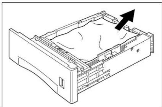
natural_image
Line drawing of a computer motherboard showing internal components and a black arrow indicating motion (no text or symbols)- Push the paper trays back into the printer and optional feeders.
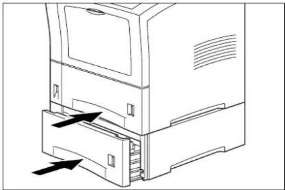
natural_image
Line drawing of a computer tower with an open drawer and directional arrows indicating movement (no text or symbols)Correcting Miscellaneous Paper Feeder Problems
Some paper feeder problems may not cause an error message and may not interfere with the operation of the printer. If you are experiencing one of the problems listed below and there is no error message shown on the control panel display, refer to the procedures in the following sections to check the possible causes of the specific problem.
■ Inoperative paper feeder
- Erratic operation
■ Unusual noise
Inoperative 550 Sheet Paper Feeder
The following characteristics define this feeder problem:
■ The feeder appears to be inoperative.
■ When attempting to print from the feeder, the feeder does not respond and does not feed paper.
■ The control panel does not display an error code.
The following procedure guides you through multiple actions that may solve this feeder problem. Proceed one step at a time until the problem is solved—you may not need to complete the entire procedure. If one of the steps in this procedure corrects the problem but the identical problem returns in less than 50 prints, call for service.
- Open and then firmly close all of the printer and feeder doors and covers.
Interlock switches monitor the position of printer doors and covers. When a door is closed, the interlock switch is activated and the feeder can operate. When a door is open, the interlock switch is not activated and the feeder cannot operate. If a door is not firmly closed, the interlock switch may not be fully activated—resulting in an inoperative feeder.
- Test the printer by printing a few sheets from the main tray.
If you cannot print a sheet of paper from the main tray and the printer does not display an error code, go to "Inoperative Printer" on page 5-3. If you can print a sheet of paper from the main tray, proceed to the next step.
-
Examine the printer driver settings to make sure the 550 sheet paper feeder is available as an installed option.
-
If the 550 sheet feeder is correctly set as an installed option, reload the printer driver software.
The printer driver software running on the host computer may be damaged. Reinstalling the software is an easy and inexpensive way to isolate or eliminate the problem. Refer to the DRIVERS folder on the Electronic Library CD-ROM for detailed instructions on installing the driver.
- Call your service technician.
This problem may be caused by a malfunctioning or broken component that requires service.
Feeder Operates Erratically
The following characteristics define this feeder problem:
■ The feeder does not function correctly.
■ The control panel does not display an error code.
The following procedure guides you through multiple actions that may solve this feeder problem. Proceed one step at a time until the problem is solved—you may not need to complete the entire procedure. If one of the steps in this procedure corrects the problem but the identical problem returns in less than 50 prints, call for service.
- Open and then firmly close all of the printer and feeder doors and covers.
Interlock switches monitor the position of printer doors and covers. When a door is closed, the interlock switch is activated and the feeder can operate. When a door is open, the interlock switch is not activated and the feeder cannot operate. If a door is not firmly closed, the interlock switch can bounce between being activated and being not activated - confusing the system and causing erratic operation.
- Reinstall the printer driver software.
The printer driver software running on the host computer may be damaged. Reinstalling the software is an easy and inexpensive way to isolate or eliminate the problem. Refer to the DRIVERS folder on the Electronic Library CD-ROM for detailed instructions on installing the drivers.
- Call your service technician.
This problem may be caused by a malfunctioning or broken component that requires service.
Feeder Makes Unusual Noises
The following characteristics define this feeder problem:
■ The feeder makes unusual noises or makes more noise than usual either while idle or while printing.
■ The feeder feeds paper without a problem.
■ The control panel does not display an error code.
The following procedure guides you through multiple actions that may solve this feeder problem. Proceed one step at a time until the problem is solved—you may not need to complete the entire procedure. If one of the steps in this procedure corrects the problem but the identical problem returns in less than 50 prints, call for service.
- Remove the paper trays and inspect the inside of the feeder for jammed paper or obviously broken components.
Broken components or scraps of paper lodged inside the feeder may be brushing against moving parts and causing the noise. - Call your service technician.
This problem may be caused by a malfunctioning or broken component that requires service.
Maintaining the 550 Sheet Feeder
The 550 sheet feeder requires very little maintenance; however, normal daily use requires you to perform some routine maintenance including replacing parts of the feeder.
Replacing Feed Roll, Nudger Roll, and Retard Roll
Rubber feed rolls drive sheets of paper out of the feeder paper trays into the printer. These feed rolls wear with normal use and eventually become coated with paper dust and must be replaced. Frequent feed jams in the front tray or main tray indicate that the feed rolls need to be replaced.
NOTE: The following procedure illustrates the process of replacing the feed roll, retard roll, and nudger roll for the main paper tray. To replace the rolls for a paper feeder, use the same procedure but remove the paper tray of the paper feeder and replace the feed rolls in the paper tray well of that feeder.
- Turn the printer off by pressing the [O] on the power switch on the right side of the printer, and disconnect the AC power cord from the wall outlet.
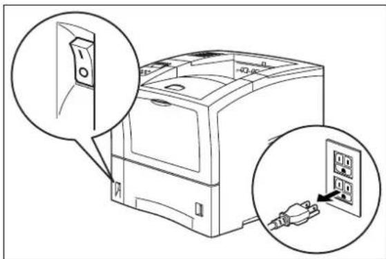
natural_image
Line drawing of a printer with two views of its internal components (no text or symbols present)- Remove the paper tray of the feeder that you intend to clean and set it on a flat level surface.

natural_image
Line drawing of a computer monitor with an open drawer and a black arrow indicating left-side motion (no text or symbols)- Pull the metal stopper plate down.

natural_image
Diagram showing a computer monitor with an inset close-up of its internal components (no text or symbols visible)- Unclip the retaining tabs on the end of the feed roll and nudger roll, and remove the rolls from their shafts.

- Push the new feed roll and nudger roll onto their shafts until the retaining tabs click into place. Make sure the tabs are toward the right side of the printer.

- Release the metal stopper plate inside the printer so it returns to its normal position.
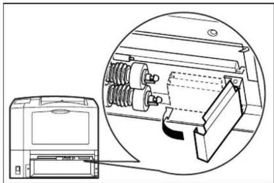
natural_image
Technical line drawing of a computer monitor with an inset close-up showing internal components (no text or symbols)- Press the locks on the left and right of the retard roll inside the paper tray, and lift the lever to open the retard roll cover.
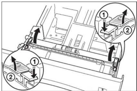
- Unclip the retaining tab on the retard roll and remove it from the shaft.
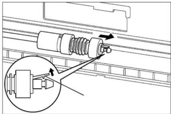
- Push the new retard roll onto the shaft until the retaining tab clicks into place. Make sure the retaining tab is toward the right side of the printer.

- Close the retard roll cover.

natural_image
Technical line drawing of a mechanical assembly with two arrows indicating directional components (no text or symbols present)- Grasp the paper tray with both hands and insert it into the paper tray well on the printer.

natural_image
Line drawing of hands installing or adjusting a mechanical component into a rack (no text or symbols visible)- Push the paper tray all the way into the printer, making sure the tray is properly seated.

natural_image
Line drawing of a computer monitor with an open lid and drive base (no text or symbols)Removing the 550 Sheet Feeder
Use the following procedure to remove the 550 sheet feeder:
- Turn the printer off by pressing the [O] on the power switch on the front left of the printer.

natural_image
Line drawing of a computer tower with an open door and magnified detail view (no text or symbols)- Disconnect the power cord from the AC outlet.

natural_image
Diagram of a computer tower with two zoomed-in insets showing internal components (no text or symbols present)
CAUTION: Removing or installing the paper feeder while the printer is on may damage the printer or paper feeder.
- Close the front tray and remove any printed sheets from the paper output tray.

natural_image
Line drawing of a computer monitor with ventilation slots and a scroll wheel (no text or symbols)- Remove the paper trays from the 550 sheet feeder and the printer.
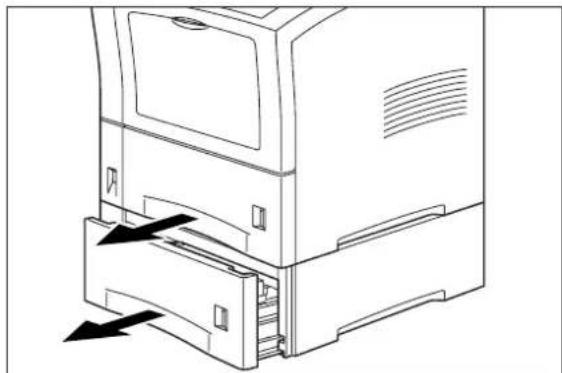
natural_image
Line drawing of a computer tower with an open door and internal drawer, showing directional arrows indicating movement (no text or symbols)- Remove the three screws that secure the printer to the paper feeder.
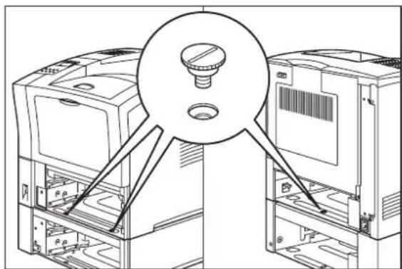
natural_image
Technical line drawing of a computer rack with a central knob and multiple compartments (no text or symbols)- Lift the printer to remove it from the feeder.
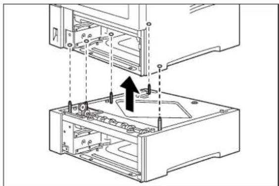
natural_image
Technical line drawing of a computer case with internal components and mounting points (no text or symbols)Moving the 550 Sheet Feeder
When moving the printer a short distance, you may leave the 550 sheet paper feeder attached. However, when moving the printer a long distance, please remove the 550-sheet paper feeder to avoid damaging either the printer or the feeder.
Moving the Printer and 550 Sheet Feeder a Short Distance
Use the following procedure to move the printer and 550 sheet feeder a short distance:
- Turn the printer off by pressing the [O] on the power switch on the back of the printer.
- Unplug the AC power cord from the AC wall outlet.
- Disconnect the printer from the host computer.
- Wait 30 minutes for the printer to cool.
- Remove the toner cartridge and cover it with an opaque plastic sheet.
- With the help of another person, carefully lift the printer and attached 550 sheet feeder and move them to the new location.
- Once the printer is in the new location, refer to the Installation Guide included in the original printer packaging to reinstall the printer.
Moving the Printer and 550 Sheet Feeder a Long Distance
Use the following procedure to move the printer and 550 sheet feeder a long distance:
- Turn the printer off by pressing the [O] on the power switch on the right side of the printer.
- Unplug the AC power cord from the wall outlet and from the back of the printer.
- Disconnect the printer from the host computer.
- Remove the paper from all of the paper trays.
- Wait 30 minutes for the printer to cool.
- Remove the main paper tray.
- Reach inside the open top tray and locate the two thumbscrews that are at the front left and front right of the feeder.
- Unscrew the two thumbscrews to release the feeder from the printer.
- Lift the printer off of the 550 sheet feeder and place it on the floor or on a table.
- Repack the feeder in the original shipping box.
- Remove the toner cartridge and place it in an opaque plastic bag, then seal the bag with tape and place it in a sturdy box.
- Repack the printer, paper trays, AC power cord and toner cartridge into the original shipping box or boxes.
- Once the feeder is in the new location, refer to "Installing the 550 Sheet Paper Feeders" on page 7-3 to reinstall the paper feeder(s).
Chapter 8
Using the Envelope Feeder
■ "About this Chapter" on page 8-2
■ "About the Envelope Feeder" on page 8-2
■ "Installing the Envelope Feeder" on page 8-2
■ "Testing the Envelope Feeder" on page 8-4
■ "Selecting Print Media" on page 8-4
■ "Loading the Envelope Feeder" on page 8-6
■ "Solving Envelope Feeder Problems" on page 8-7
■ "Maintaining the Envelope Feeder" on page 8-13
8-2 TallyGenicom Intelliprint mL260 User Guide About the Envelope Feeder
About this Chapter
This chapter provides all of the information necessary to install, use, and maintain the envelope feeder, including procedures for removing paper jams.
About the Envelope Feeder
The Envelope Feeder is an optional single-tray feeder that attaches to the front of the printer. The tray holds 50 to 100 envelopes or postcards, depending on the type of media.
Installing the Envelope Feeder
Before installing the envelope feeder, verify that you have received the following items in the shipping box:
Ins

natural_image
Technical line drawing of a mechanical component with internal slots and a directional arrow (no text or symbols)Envelope FeederInstallation Sheet
Installing the Envelope Feeder
Use the following procedure to install the envelope feeder:

WARNING: Before installing any options, turn the printer off by pressing [O] on the power switch on the right side of the unit and disconnect the power cord from the AC outlet. These precautions are necessary to avoid the risk of electric shock.
- Turn the printer off by pressing [O] on the power switch on the right side of the unit, and disconnect the power cord from the AC outlet.

NOTE: Installing the envelope feeder while the printer is on may damage the printer or the envelope feeder.
- Remove the envelope feeder from its packaging and place it on a level surface. Remove any cardboard inserts and packing tape.

natural_image
Technical line drawing of a mechanical component with internal cavities and mounting brackets (no text or symbols)- Pull on the recessed area on the front of the printer to open the front tray.

natural_image
Line drawing of a computer monitor with an arrow indicating the open lid (no text or symbols present)- Remove the gear cover on the left side of the inside of the printer and store it in a safe place.

natural_image
Technical line drawing of a mechanical device with an inset showing a component being inserted (no text or symbols present)- Push the envelope feeder all the way into the printer until it stops, making sure it is seated firmly inside the printer.

natural_image
Line drawing of a computer printer internal structure with an open lid and arrow indicating a component (no text or symbols present)Testing the Envelope Feeder
After installing the envelope feeder, use the following test procedure to verify that the feeder is operating correctly.
-
Turn the printer on by pressing the [I] on the power switch on the right side of the printer.
-
Once the printer has warmed up and displays the "Ready" message on the control panel display, use any software application to print a few sheets from the envelope feeder.
-
If the feeder does not feed paper or if the control panel displays an error message, refer to "Solving Envelope Feeder Problems" on page 7.
Selecting Print Media
Your printer can print on a variety of media, including plain paper, labels, transparencies, and envelopes. Always use print media that meet the guidelines for use with this printer. Print media that is not recommended for use with this printer may cause frequent paper jams or poor print quality.
Paper and Print Media To Avoid
Do not use paper or print media that has any of the following characteristics:
■ Does not meet the paper and media size and weight specifications for this printer
■ Is not labeled for use with xerographic printers or xerographic copiers
■ Cannot withstand temperatures of up to 310^ F/ 155^ C
■ Is in a sealed package that is obviously damaged or wet
■ Is excessively wrinkled, curled, torn, or warped
■ Is folded or creased
- Has either an extremely slick surface or an extremely textured surface
■ Has an exposed adhesive surface
■ Has paper pieces glued or taped to the media
■ Has staples or paper clips attached
■ Is categorized as thermal paper, coated paper, or carbon paper
- Is an envelope that is embossed, is made of extremely thick paper, or is padded
■ Is an envelope that has metal clasps
■ Is a sheet of labels that has the backing sheet exposed between individual labels
Correct Paper Storage
It is important to store paper correctly prior to placing it in the printer, since improper storage can cause frequent paper jams and poor print quality. Use the following guidelines when storing paper for use in the printer:
■ Store reams of paper on a flat surface, and always store them stacked horizontally.
■ Store reams of paper in an area away from both direct sunlight and high humidity
- Open sealed reams only when you are ready to load the paper into the paper tray, and always close and seal partial reams of paper.
■ Do not stack partial reams of paper
Print Media Weight, Type, and Size
The following table defines print media that you can use in the envelope feeder. If you have concerns about a specific brand or type of media, try samples of the media to determine if the resulting printer performance and print quality meet your expectations.
| Type of Envelope or Postcard Maximum Capacity | ||
| Envelope Commercial # 10 75 | ||
| Monarch 75 | ||
| DL 75 | ||
| C5 50 | ||
| Postcard 100 | ||
| Custom Size 3. | 87 x 5.85 inches (98.4 x 148.5mm) to 7 x 10 inches (178 x 254mm) | Maximum stack height 0.95 inches (24mm) |
Loading the Envelope Feeder
Use the following procedure to load envelopes into the envelope feeder:
- If you are planning to use large size envelopes, pull out the extension at the end of the paper tray.

natural_image
Line drawing of a printer's internal structure showing internal components and a black arrow indicating a component (no text or symbols present)- Lift up the paper holder, align the four corners of the stack of envelopes or postcards, and gently insert them into the envelope feeder until they reach the back of the feeder.
NOTE: Do not use envelopes or postcards that are creased or wrinkled. Do not load more envelopes or postcards than the specified amount. If the stack of envelopes or postcards is bent, it may cause a paper jam; avoid bending envelopes when you are loading them into the envelope feeder.

natural_image
Line drawing of a hand inserting a component into a printer (no text or symbols)- Lower the paper holder.

natural_image
Line drawing of a printer internal structure showing paper feeding into a printer (no text or symbols)- Adjust the paper guide to the size of the envelopes or postcards you are using.
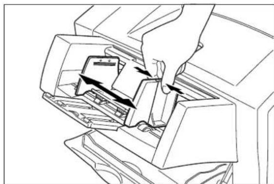
natural_image
Line drawing of a printer's internal structure with arrows indicating process flow (no text or symbols)Solving Envelope Feeder Problems
When there is a problem with the envelope feeder, the printer control panel displays an error code and error message. Most envelope feeder error codes indicate routine status conditions such as running out of paper or a paper jam. Some error codes indicate much more serious problems that may require the help of a service technician.
- If the printer control panel displays an error message or an error code, refer to "Interpreting Envelope Feeder Error Messages" on page 8-10.
If you have an envelope feeder problem but the printer control panel does not display an error message or error code, refer to "Correcting Miscellaneous Envelope Feeder Problems" on page 8-10 and follow the directions for correcting that problem.
Envelopes Become Creased when Printing
If envelopes are creased or wrinkled after printing, lift up the fuser release levers at the left and right side of the fuser unit, and try printing again. The printed image may appear thin using this method, but the envelopes will not be creased or wrinkled.
Use the following procedure to lift the fuser release levers:
- If you are using the paper tray in its extended position, remove it from the printer.

natural_image
Line drawing of hands installing or adjusting a mechanical component on a device chassis (no text or symbols visible)- Squeeze the tabs on the rear cover and pull the cover toward you to open it.

natural_image
Diagram of a computer oven with a close-up view showing two boxes and a scroll inside (no text or symbols)- Lift up the fuser release levers at the left and right side of the fuser unit.

natural_image
Diagram of a computer tower internal structure with an arrow indicating rotation direction (no text or symbols present)- Remove the caps (green) on the inside of the rear cover at the left and right.

natural_image
Technical line drawing of a mechanical assembly with an inset magnified view of a component (no text or symbols)- Store the caps in the holes provided on the inside of the rear cover.
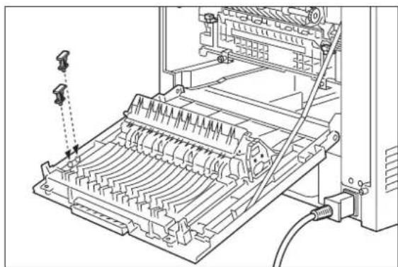
natural_image
Technical line drawing of a mechanical device with internal components and a cable (no text or symbols)- Close the rear cover.

natural_image
Line drawing of a computer monitor with an arrow indicating the left side of the screen (no text or symbols present)Interpreting Envelope Feeder Error Messages
The printer control panel displays error messages when there is a problem with the printer or any of the optional paper-handling components. The following table lists all of the error messages associated with the envelope feeder, the possible cause of the error, and the action to take to correct the problem. If the control panel shows an error message that concerns another part of the printer, refer to Chapter 5: Troubleshooting for a complete list of all warning and error messages.
| Error or Warning Message Line 1 | Error or Warning Message Line 2 | Possible Cause Action | |
| LOAD ENVELOPE Paper Size/Paper Type The envelope tray is empty. | Load print media into the envelope tray. | ||
| ENV UNIT FAILURE Check Feeder The envelope feeder has been removed or has failed. | Check the envelope feeder to make sure it is properly installed. Turn the printer off, then on. If the problem reoccurs, contact your service provider. | ||
Correcting Miscellaneous Envelope Feeder Problems
Some envelope feeder problems may not cause an error message and may not interfere with the operation of the printer. If you are experiencing one of the problems listed below and there is no error message shown on the control panel display, refer to the procedures in the following sections to check the possible causes of the specific problem.
■ Inoperative envelope feeder
- Erratic operation
■ Unusual noise
Inoperative Envelope Feeder
The following characteristics define this feeder problem:
■ The envelope feeder appears to be inoperative.
- When attempting to print from the envelope feeder, the envelope feeder does not respond and does not feed paper.
■ The control panel does not display an error code.
The following procedure guides you through multiple actions that may solve this feeder problem. Proceed one step at a time until the problem is solved—you may not need to complete the entire procedure. If one of the steps in this procedure corrects the problem but the identical problem returns in less than 50 prints, call for service.
- Open and then firmly close all of the printer and feeder doors and covers.
Interlock switches monitor the position of printer doors and covers. When a door is closed, the interlock switch is activated and the envelope feeder can operate. When a door is open, the interlock switch is not activated and the envelope feeder cannot operate. If a door is not firmly closed, the interlock switch may not be fully activated—resulting in an inoperative envelope feeder.
- Test the printer by printing a few sheets from the main tray.
If you cannot print a sheet of paper from the main tray and the printer does not display an error code, go to "Inoperative Printer" on page 5-3. If you can print a sheet of paper from the main tray, proceed to the next step.
-
Examine the printer driver settings to make sure the envelope feeder is available as an installed option.
-
If the envelope feeder is correctly set as an installed option, reload the printer driver software.
The printer driver software running on the host computer may be damaged. Reinstalling the software is an easy and inexpensive way to isolate or eliminate the problem. Refer to the DRIVERS folder on the Electronic Library CD-ROM for detailed instructions on installing the driver.
- Call your service technician.
This problem may be caused by a malfunctioning or broken component that requires service.
Feeder Operates Erratically
The following characteristics define this envelope feeder problem:
■ The envelope feeder does not function correctly.
■ The envelope feeder does not feed paper, or feeds paper without a request.
■ The control panel does not display an error code.
The following procedure guides you through multiple actions that may solve this envelope feeder problem. Proceed one step at a time until the problem is solved—you may not need to complete the entire procedure. If one of the steps in this procedure corrects the problem but the identical problem returns in less than 50 prints, call for service.
- Open and then firmly close all of the printer and envelope feeder doors and covers.
Interlock switches monitor the position of printer doors and covers. When a door is closed, the interlock switch is activated and the envelope feeder can operate. When a door is open, the interlock switch is not activated and the envelope feeder cannot operate. If a door is not firmly closed, the interlock switch can bounce between being activated and being not activated - confusing the system and causing erratic operation.
- Reinstall the printer driver software.
The printer driver software running on the host computer may be damaged. Reinstalling the software is an easy and inexpensive way to isolate or eliminate the problem. Refer to the DRIVERS folder on the Electronic Library CD-ROM for detailed instructions on installing the drivers.
- Call your service technician.
This problem may be caused by a malfunctioning or broken component that requires service.
Envelope Feeder Makes Unusual Noises
The following characteristics define this envelope feeder problem:
■ The envelope feeder makes unusual noises or makes more noise than usual either while idle or while printing.
■ The envelope feeder feeds paper without a problem.
■ The control panel does not display an error code.
The following procedure guides you through multiple actions that may solve this envelope feeder problem. Proceed one step at a time until the problem is solved—you may not need to complete the entire procedure. If one of the steps in this procedure corrects the problem but the identical problem returns in less than 50 prints, call for service.
- Remove the paper trays and inspect the inside of the envelope feeder for jammed paper or obviously broken components.
Broken components or scraps of paper lodged inside the envelope feeder may be brushing against moving parts and causing the noise.
- Call your service technician.
This problem may be caused by a malfunctioning or broken component that requires service.
Maintaining the Envelope Feeder
The envelope feeder requires very little maintenance; however, with normal use you will need to perform some routine maintenance tasks such as cleaning the envelope feeder.
Cleaning the Exterior of the Envelope Feeder
Through normal use the exterior of the envelope feeder may become dirty or stained with toner. Although exterior dirt should not affect printer performance, an occasional exterior cleaning may be necessary to maintain the appearance of the envelope feeder.
-
Turn the printer off by pressing [O] on the power switch on the right side of the printer.
-
Remove the plug of the AC power cord from the AC wall outlet.
-
Using a soft cloth, slightly damp with cold water, wipe the envelope feeder covers and tray faces. Use a very mild, non-abrasive soap to remove heavy dirt and toner stains.

CAUTION: Do not use solvents or abrasive cleaners to clean envelope feeder covers. Use only cold water and a very mild soap to clean covers.
-
Using a soft, dry cloth, thoroughly dry the covers and tray faces.
-
Insert the plug of the AC power cord into the AC wall outlet, and turn the printer on by pressing [I] on the power switch on the right side of the printer.
Chapter 9
Using the Offset Catch Tray
In this Chapter . . .
■ "About this Chapter" on page 9-2
■ "About the Offset Catch Tray" on page 9-2
■ "Installing the Offset Catch Tray" on page 9-3
■ "Testing the Offset Catch Tray" on page 9-7
■ "Solving Offset Catch Tray Problems" on page 9-7
■ "Maintaining the Offset Catch Tray" on page 9-13
■ "Removing the Offset Catch Tray" on page 9-13
■ "Moving the Offset Catch Tray" on page 9-16
About this Chapter
This chapter provides all of the information necessary to install, use, and maintain the Offset Catch Tray, including procedures for cleaning and removing paper jams.
About the Offset Catch Tray
The offset catch tray is an optional output tray that attaches to the top rear of the printer and can hold up to 500 printed sheets, and also sorts printed sheets using an offset. The printer supplies all of the operating power that is needed by the offset catch tray. Motors and circuit boards internal to the offset catch tray provide it with drive and operational logic.
The offset catch tray can be installed with only the printer, or it may be installed with other paper-handling options.
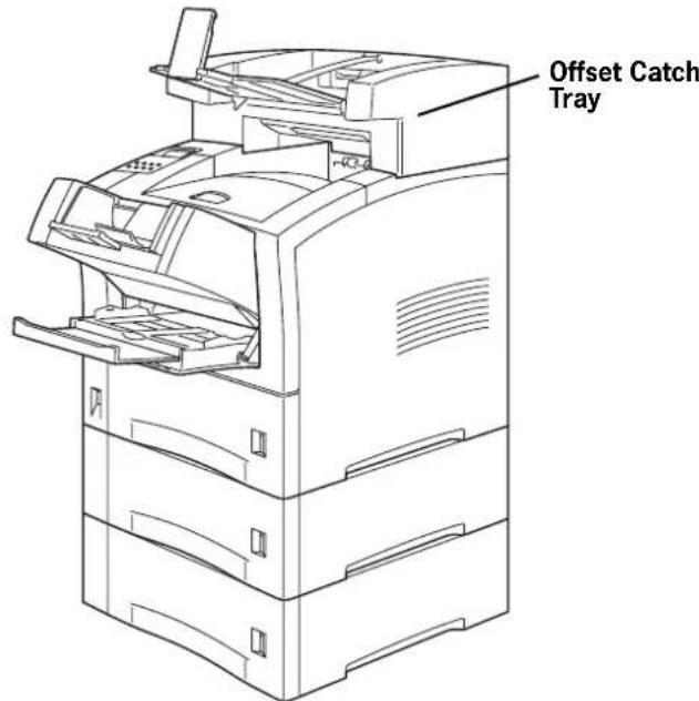
Figure 9-1: Offset Catch Tray installed with other paper handling options.
Major Components of the Offset Catch Tray
The following illustration shows the major components of the offset catch tray:.

Figure 9-2: Offset Catch Tray Major Components.
Installing the Offset Catch Tray
Before installing the offset catch tray, remove it from its packaging and verify that you have received an offset catch tray and that it is in good condition. If any part of the offset catch tray is missing or damaged, contact your dealer.
Throughout this procedure, the different sides of the printer are referred to as front, rear, left, and right. The front of the printer is the side that holds the control panel. The left and right sides are those to the left and right, respectively, of a person facing the front of the printer.
Use the following procedure to install the offset catch tray:
-
Remove any cardboard inserts or packing tape from the interior and exterior of the offset catch tray.
-
Turn the printer off by pressing [O] on the power switch on the front left of the printer, and disconnect the power cord from the AC outlet.
NOTE: Installing the offset catch tray while the printer is on may damage the printer or the offset catch tray.

- Squeeze the latch on the top left of the rear cover to release the cover, then open the rear cover by pulling down on the top of the cover.

natural_image
Line drawing of a computer oven with a magnified inset showing two boxes inside (no text or symbols)- Push up on the top cover tabs to release the top cover, and lift it off of the printer.

natural_image
Technical diagram of a mechanical device with internal components and directional arrows indicating flow or movement (no text or symbols present)- Lower the offset catch tray onto the printer while inserting the stub at the front of the offset catch tray into the hole on the top of the printer.
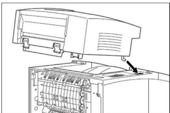
natural_image
Technical line drawing of a computer monitor with an open rear panel showing internal components (no text or symbols)- Insert the tabs on the back of the offset catch tray into the holes on the back of the printer, and push down until you hear the tabs click in place.
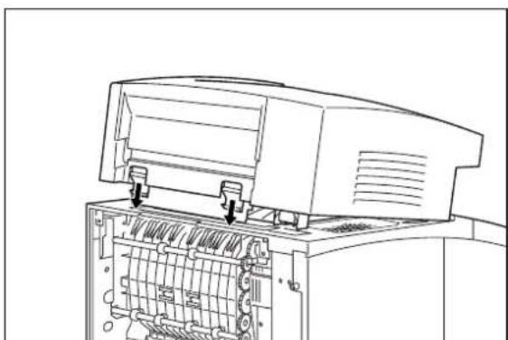
natural_image
Technical line drawing of an open industrial machine with internal components (no text or symbols)- Close the rear cover.

natural_image
Line drawing of a computer monitor with an open lid and cable, showing internal structure and a circular arrow indicating rotation (no text or symbols)- Lift up the paper guide and open the offset tray.

natural_image
Line drawing of a mechanical device interior with a highlighted component (no text or symbols)- Pull the tray all the way out and lift the paper stop.

- Push the tray in until it matches the size of paper that will be printed.
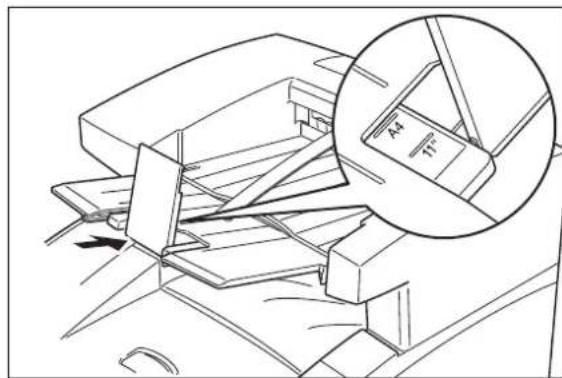
natural_image
Technical line drawing of a mechanical assembly with an inset showing a component labeled 'E' (no text or symbols present)-
Insert the plug of the power cord into the AC outlet and turn the printer on by pressing [I] on the power switch on the front left of the printer.
-
Check the display to make sure the printer is ready for printing.
NOTE: If an error message is shown when you turn the printer on, refer to Chapter 5: Troubleshooting.
Testing the Offset Catch Tray
After installing the offset catch tray, use the following test procedure to verify that it is operating correctly.
-
Turn the printer on by pressing the [I] on the power switch on the front left of the printer.
-
Once the printer has warmed up and displays the "Ready" message on the control panel display, use any software application to print a few sheets to the offset catch tray.
-
If the feeder does not feed paper or if the control panel displays an error message, refer to "Solving Offset Catch Tray Problems" on page 9-7.
Solving Offset Catch Tray Problems
When there is a problem with the offset catch tray, the printer control panel displays an error code and error message. Most offset catch tray error codes indicate routine status conditions such as a paper jam. Some error codes indicate much more serious problems that may require the help of a service technician.
- If the offset catch tray is inoperative after installation, refer to "Installation Problems" on page 9-8 and complete the recommended procedure.
- If the printer control panel displays an error message or an error code, refer to "Interpreting Offset Catch Tray Error Messages" on page 9-8.
If you have an offset catch tray problem but the printer control panel does not display an error message or error code, refer to "Correcting Miscellaneous Offset Catch Tray Prob-
lems" on page 9-10 and follow the directions for correcting that problem.
Interpreting Offset Catch Tray Error Messages
The printer control panel displays error messages when there is a problem with the printer or any of the optional paper-handling components. The following table lists all of the error messages associated with the offset catch tray, the possible cause of the error, and the action to take to correct the problem. If the control panel shows an error message that concerns another part of the printer, refer to Chapter 5: Troubleshooting for a complete list of all warning and error messages.
| Error or Warning Message Line 1 | Error or Warning Message Line 2 | Possible Cause Action | |
| (Warning message, printer continues operating and line 1 shows printer status.) | Offset Tray Full The offset catch tray is full. | Remove paper from the tray. | |
| E6 JAM OFF. TRAY Remove paper There is a jam at the offset catch tray. | Remove the paper jam.See “Clearing an Offset Catch Tray Paper Jam” on page 9-9. | ||
| OFFSET TRAY FULL Remove Paper The offset catch tray is full. | Remove paper from the tray. | ||
| OFFSET TRAY FAIL | Call Service | The offset tray has failed. | Turn the printer off, then turn it on. If the problem reoccurs, contact an authorized service provider. |
Installation Problems
Simple oversights during installation may cause problems when you first use the offset catch tray. If the offset catch tray is inoperative after you have installed it, use the following procedure to check several possible causes.
-
Turn the printer off by pressing the [O] on the power switch on the right side of the printer.
-
Make sure that the offset catch tray is firmly attached to the printer.
If the offset catch tray is firmly attached but the offset catch tray is still inoperative, return to the installation procedure and carefully repeat all of the installation steps.
-
If the offset catch tray is still inoperative after reinstallation, remove it from the printer so you can run tests on the printer alone.
-
Print a few sheets of paper to the main output tray to make sure the printer is still operational.
- If the printer is operational when the offset catch tray is not attached, contact either your sales representative or a service technician and report your problem.
- If the printer is not operational when the offset catch tray is not attached, refer to Chapter 5: Troubleshooting for procedures to correct printer problems. After correcting the printer problem, return to this chapter to reinstall the offset catch tray.
Clearing an Offset Catch Tray Paper Jam
If an E6 error code precedes the error message on the first line of the control panel display, paper has jammed at the offset catch tray. Use the following procedure to clear a paper jam in this location:
- Pull on the recessed area on the rear of the offset catch tray to open the rear cover.

natural_image
Line drawing of a printer with an arrow indicating compression or disassembly (no text or symbols present)- Remove any jammed paper from the interior of the offset catch tray.
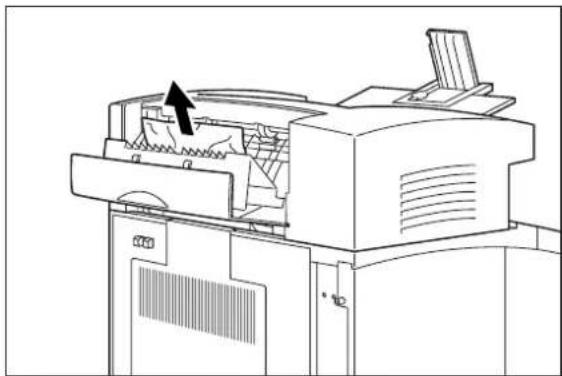
natural_image
Line drawing of a printer with an arrow indicating the paper's front cover (no text or symbols present)- Close the rear cover of the offset catch tray.
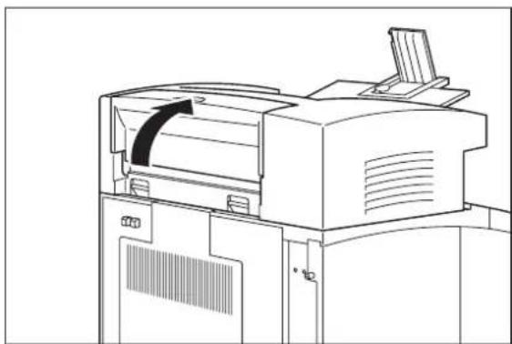
natural_image
Line drawing of a printer with front panel and side cover (no text or symbols)- Squeeze the latch on the upper part of the rear cover, and pull the cover toward you to open it. Remove any paper that is stuck behind the rear cover.
NOTE: If the main paper tray is in the extended position, remove the tray before opening the rear cover.

- Close the rear cover.

natural_image
Line drawing of a computer oven with an arrow indicating a scroll or rotation (no text or symbols present)Correcting Miscellaneous Offset Catch Tray Problems
Some offset catch tray problems may not cause an error message and may not interfere with the operation of the printer. If you are experiencing one of the problems listed below and there is no error message shown on the control panel display, refer to the procedures in the following sections to check the possible causes of the specific problem.
■ Inoperative offset catch tray
- Erratic operation
■ Unusual noise
Inoperative Offset Catch Tray
The following characteristics define this feeder problem:
■ The offset catch tray appears to be inoperative.
- When attempting to print to the offset catch tray, the offset catch tray does not respond and does not transport paper.
■ The control panel does not display an error code.
The following procedure guides you through multiple actions that may solve this offset catch tray problem. Proceed one step at a time until the problem is solved—you may not need to complete the entire procedure. If one of the steps in this procedure corrects the problem but the identical problem returns in less than 50 prints, call for service.
- Open and then firmly close all of the printer and offset catch tray doors and covers.
Interlock switches monitor the position of printer doors and covers. When a door is closed, the interlock switch is activated and the offset catch tray can operate. When a door is open, the interlock switch is not activated and the offset catch tray cannot operate. If a door is not firmly closed, the interlock switch may not be fully activated—resulting in an inoperative offset catch tray.
- Examine the printer driver settings to make sure the offset catch tray is available as an installed option. If the offset catch tray is correctly set as an installed option, reload the printer driver software.
The printer driver software running on the host computer may be damaged. Reinstalling the software is an easy and inexpensive way to isolate or eliminate the problem. Refer to the DRIVERS folder on the Electronic Library CD-ROM for detailed instructions on installing the driver.
- Call your service technician.
This problem may be caused by a malfunctioning or broken component that requires service.
Offset Catch Tray Operates Erratically
The following characteristics define this offset catch tray problem:
■ The offset catch tray does not function correctly.
■ The offset catch tray does not transport paper, or transports paper without a request.
■ The control panel does not display an error code.
The following procedure guides you through multiple actions that may solve this offset catch tray problem. Proceed one step at a time until the problem is solved—you may not need to complete the entire procedure. If one of the steps in this procedure corrects the problem but the identical problem returns in less than 50 prints, call for service.
- Open and then firmly close all of the printer and offset catch tray doors and covers.
Interlock switches monitor the position of printer doors and covers. When a door is closed, the interlock switch is activated and the offset catch tray can operate. When a door is open, the interlock switch is not activated and the offset catch tray cannot operate. If a door is not firmly closed, the interlock switch can bounce between being activated and being not activated—confusing the system and causing erratic operation.
- Reinstall the printer driver software.
The printer driver software running on the host computer may be damaged. Reinstalling the software is an easy and inexpensive way to isolate or eliminate the problem. Refer to the DRIVERS folder on the Electronic Library CD-ROM for detailed instructions on installing the drivers.
- Call your service technician.
This problem may be caused by a malfunctioning or broken component that requires service.
Offset Catch Tray Makes Unusual Noises
The following characteristics define this offset catch tray problem:
- The offset catch tray makes unusual noises or makes more noise than usual either while idle or while printing.
■ The offset catch tray transports paper without a problem.
■ The control panel does not display an error code.
The following procedure guides you through multiple actions that may solve this offset catch tray problem. Proceed one step at a time until the problem is solved—you may not need to complete the entire procedure. If one of the steps in this procedure corrects the problem but the identical problem returns in less than 50 prints, call for service.
- Open the offset catch tray cover and inspect the inside for jammed paper or obviously damaged parts.
Broken components or scraps of paper lodged inside the offset catch tray may be brushing against moving parts and causing the noise.
- Call your service technician.
This problem may be caused by a malfunctioning or broken component that requires service.
Offset Catch Tray will not Offset
The following characteristics define this offset catch tray problem:
■ The offset catch tray does not offset printed sheets.
■ The offset catch tray transports paper without a problem.
■ The control panel does not display an error code.
The following procedure guides you through multiple actions that may solve this offset catch tray problem. Proceed one step at a time until the problem is solved—you may not need to complete the entire procedure. If one of the steps in this procedure corrects the problem but the identical problem returns in less than 50 prints, call for service.
- Open the offset catch tray cover and inspect the inside for jammed paper or obviously damaged parts.
Broken components or scraps of paper lodged inside the offset catch tray may be wedged against moving parts, preventing the offset roll from moving.
- Call your service technician.
This problem may be caused by a malfunctioning or broken component that requires service.
Maintaining the Offset Catch Tray
The offset catch tray requires very little maintenance; however, with normal use you will need to perform some routine maintenance tasks such as cleaning.
Cleaning the Exterior of the Offset Catch Tray
Through normal use the exterior of the offset catch tray may become dirty or stained with toner. Although exterior dirt should not affect printer performance, an occasional exterior cleaning may be necessary to maintain the appearance of the offset catch tray.
-
Turn the printer off by pressing [O] on the power switch on the right side of the printer.
-
Remove the plug of the AC power cord from the AC wall outlet.
-
Using a soft cloth, slightly damp with cold water, wipe the offset catch tray covers and tray faces. Use a very mild, non-abrasive soap to remove heavy dirt and toner stains.

CAUTION: Do not use solvents or abrasive cleaners to clean offset catch tray covers. Use only cold water and a very mild soap to clean covers.
-
Using a soft, dry cloth, thoroughly dry the covers and tray faces.
-
Insert the plug of the AC power cord into the AC wall outlet, and turn the printer on by pressing [I] on the power switch on the right side of the printer.
Removing the Offset Catch Tray
Use the following procedure to remove the offset catch tray:
- Pull the output tray all the way out and lower the paper stop.

- Push the paper stop into the output tray.

natural_image
Line drawing of a printer's internal structure showing handle, spool, and paper feed (no text or symbols)- Lift the paper guide and fold up the output tray.
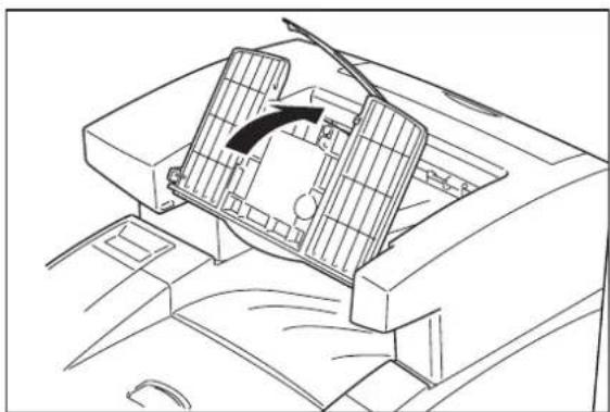
natural_image
Line drawing of a car interior showing the intake manifold and airflow direction (no text or symbols)- Turn the printer off by pressing [O] on the power switch on the front left of the printer, and disconnect the power cord from the AC outlet.
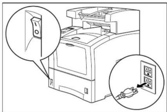
- Squeeze the latch on the upper left of the rear cover of the printer, and pull the cover toward you to open it.
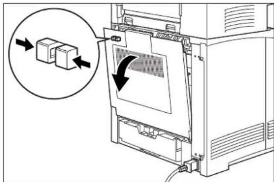
natural_image
Diagram of a computer oven with a close-up view showing two boxes inside, no text or symbols present- Press the tabs on the rear of the offset catch tray to release it and lift it off of the printer.

natural_image
Technical line drawing of a computer printer internal structure with arrows indicating ports (no text or symbols)- Replace the top cover of the printer.

- Close the rear cover of the printer.

natural_image
Line drawing of a computer monitor with an arrow indicating the left side of its screen (no text or symbols present)Moving the Offset Catch Tray
Moving the Offset Catch Tray a Short Distance
Use the following procedure to move the offset catch tray a short distance:
-
Turn the printer off by pressing the [O] on the power switch on the right side of the printer.
-
Disconnect the plug of the AC power cord from the AC wall outlet.
-
Disconnect the printer from the host computer.
-
Wait 30 minutes for the printer to cool before moving the printer.
-
Remove the toner cartridge and cover it with an opaque plastic sheet.
-
With the help of another person, grasp the recessed areas on the bottom of the printer and lift the printer. Carefully carry the printer to the new location.
-
Once the printer and offset catch tray are in the new location, refer to the printer Installation Guide included in the original packaging to reinstall the printer.
Moving the Offset Catch Tray a Long Distance
-
Turn the printer off by pressing the [O] on the power switch on the right side of the printer.
-
Disconnect the plug of the AC power cord from the AC wall outlet, and disconnect the AC power cord from the printer.
-
Disconnect the printer from the host computer.
-
Fold the output paper tray into the offset catch tray.
-
Remove the offset catch tray off of the printer. Refer to "Removing the Offset Catch Tray" on page 9-13 for complete instructions.
-
Remove the offset catch tray cover from the top rear of the printer and replace it with the original printer cover.
-
Repack the offset catch tray components in the original packaging.
-
Once the offset catch tray is in the new location, refer to "Installing the Offset Catch Tray" on page 9-3.
Chapter 10
Optional Extended Features
In this Chapter . . .
■ "About this Chapter" on page 10-2
■ "Installing DRAM Memory DIMMS" on page 10-2
■ "Installing a FLASH DIMM Module" on page 10-5
■ "Using the Hard Disk Option and User Flash DIMM Module" on page 10-9
■ "Using the Power-On Files Feature" on page 10-15
■ "Collating, Saved Jobs, and Job Accounting" on page 10-16
■ "Using the Custom Paper Size Feature" on page 10-27
■ “Custom Page size and Microsoft Word, Word 2000, and Word 2003” on page 10-31
■ “Accessing the Printer Web Page” on page 10-33
■ "Using the RS-232C/RS-422 Serial Interface" on page 10-48
About this Chapter
This chapter describes the procedures for installation of DRAM Memory DIMMs and FLASH DIMMS. Also describes how to use the extended features associated with these options.
Installing DRAM Memory DIMMS
Removing Printer Side Cover
- Ensure that the printer power switch is set to the OFF [O] position and unplug the power cord from the AC outlet.

natural_image
Diagram of a computer case with an open door and two close-up insets showing internal components (no text or symbols)- Loosen the thumbscrews at the top and bottom of the left side cover by turning them in a counter-clockwise direction.

natural_image
Diagram of a computer tower with a cable inserted into the base panel, showing internal components and a magnified inset (no text or symbols)- Slide the cover towards the rear of the printer and then downwards to remove it.

natural_image
Line drawing of a computer case with an arrow indicating a component (no text or symbols present)Installing SDRAM MEMORY DIMMs on the Controller Assembly

CAUTION: ESD-sensitive precautions should be observed when installing the SDRAM Memory DIMM.
- Carefully insert a SDRAM DIMM in any available SDRAM DIMM slot at a vertically as shown below. When properly seated, gently push down until the DIMM snaps and locks into place.
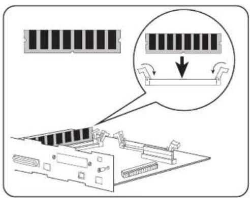
NOTE: 64MB of memory is standard in the 26ppm printer; however, you can install up to two 256MB modules for a total of 516MB.
Replacing the Printer Side Cover
- Insert the top part of the left side cover into the printer. Ensure the locking tab aligns with the hole in the printer's side.

- Slide the side cover towards the front of the printer to install it.

natural_image
Diagram of a computer case with an arrow indicating a directional flow or movement (no text or symbols present)- Tighten both thumbscrews in a clockwise direction.

natural_image
Line drawing of a computer case with a magnified inset showing a cable being inserted (no text or symbols)- Connect the power cord to the wall outlet and turn the printer power switch to the ON [I] position.

Installing a FLASH DIMM Module
Flash DIMM
This section explains the procedure for installing the FLASH DIMM Module on the controller assembly in the 26 page-per-minute printer. The procedure is divided into three main steps:
- Removing the Printer Side Cover
• Installing FLASH DIMMs on the Controller Assembly - Replacing the Printer Side Cover
Removing Printer Side Cover
- Ensure that the printer power switch is set to the OFF [O] position and unplug the power cord from the AC outlet.
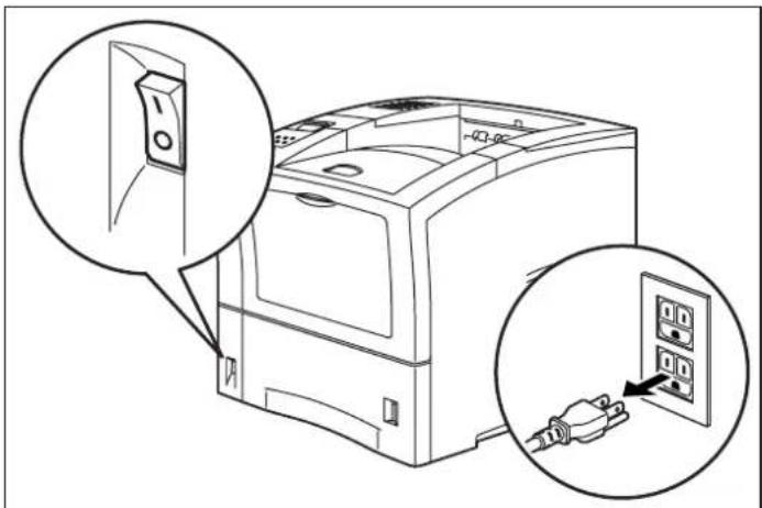
- Loosen the thumbscrews at the top and bottom of the left side cover by turning them in a counter-clockwise direction.

natural_image
Technical line drawing of a computer tower with cable insertion, showing internal components and a magnified inset (no text or symbols)- Slide the cover towards the rear of the printer and then downwards to remove it.

natural_image
Diagram of a computer case with an arrow indicating a component or operation (no text or symbols present)Installing the optional user FLASH DIMM on the Controller Assembly

CAUTION: ESD-sensitive precautions should be observed when installing the FLASH DIMM
- Carefully insert the optional user FLASH DIMM module in user FLASH DIMM vertically as shown below. When properly seated, gently push down until the DIMM snaps and locks into place.
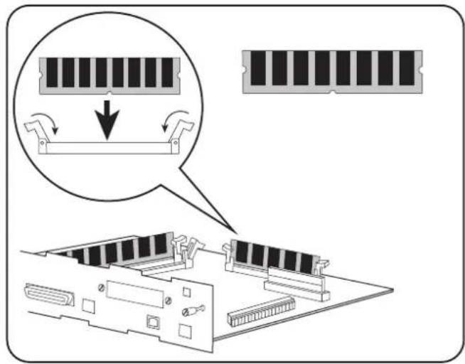
Replacing the Printer Side Cover
- Insert the top part of the left side cover into the printer. Ensure the locking tab aligns with the hole in the printer's side.

- Slide the side cover towards the front of the printer to install it.

natural_image
Line drawing of a computer tower case with an arrow indicating a directional change or movement (no text or symbols present)- Tighten both thumbscrews in a clockwise direction.
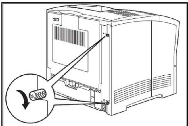
natural_image
Diagram of a computer tower with a cable being inserted, showing internal components and a magnified view of the cable (no text or symbols present)- Connect the power cord to the wall outlet and turn the printer power switch to the ON [1] position.

Loading Code from the FLASH DIMM
This section describes the procedure for loading code from a FLASH DIMM to the on-board FLASH for new production controllers that have never been programmed.
- Place the FLASH DIMM module that contains the desired code revision into the USER FLASH DIMM socket.
- Move the Jumper (J3) to DIMM Boot position.
- Simultaneously press and hold the following buttons on the printer control panel: CANCEL, NEXT and SELECT. Continue holding them down while you power ON the Printer.
- Once the control panel display reads "Copy DIMM 1 to 2", release the CANCEL, NEXT and SELECT buttons.
- Press the SELECT button again to continue the copy process.
- After a moment the control panel display reads "Copy Completed Power OFF".
- Power off the printer, remove the USER FLASH DIMM module and place the Jumper (J3) back to the Flash Boot position.
NOTE: To remove the FLASH DIMM, pull the white braces away from the ends of the DIMM until the DIMM snaps out of the slot.
Using the Hard Disk Option and User Flash DIMM Module
This section discusses the available control panel menus when the Hard Disk or User Flash option is installed. Storage of files on the Hard Disk and User Flash option are also discussed.
Operator Panel MENU Structure
When the Hard Disk or User Flash option is installed, the printer control panel menu structure is enhanced as shown in the following table. The shaded areas denote additional features and settings relevant to the Hard Disk or User Flash option.
| Menu | ||||
| Job Library | ||||
| Job Accounting | ||||
| Paper Menu | ||||
| Interface Menu | ||||
| PS Menu | ||||
| PCL Menu | ||||
| System Menu | ||||
| Display Language | ||||
| Alarm Control | ||||
| Power Saver | ||||
| Wait Timeout | ||||
| Job Timeout | ||||
| Jam Recovery | ||||
| Hex Print | ||||
| Intellifilter | ||||
| Power-On Files | ||||
| Playback FILE01.POR | ||||
| FILE02.POR | ||||
| FILE03.POR | ||||
| ... | ||||
| ... | ||||
| Delete FILE01.POR | ||||
| FILE02.POR | ||||
| FILE03.POR | ||||
| ... | ||||
| ... | ||||
| Quality Menu | ||||
| Functions | ||||
| Disk Menu | ||||
| Delete | ||||
| Format Disk | ||||
| Disk Summary | ||||
| Flash Menu | ||||
| Delete | ||||
| Format Disk | ||||
| Disk Summary | ||||
NOTE: 1. The Flash Menu and Disk Menu will only appear when the respective FLASH SIMM and/or Hard Disk option is installed.
2. Power-On Files menu will only appear if either a FLASH SIMM or a Hard Disk option is installed and power-on files exist.
Using the Disk Menu
Manipulation of files stored on the hard disk option can be accomplished using the Disk Menu.
| Disk Menu | |
| Delete | |
| Format Disk | |
| Disk Summary |
This selection will read the selected file from the Hard Disk and print it as if it were being received from one of the input ports.
Delete
This selection will delete the selected disk file or directory from the hard drive. To delete an entire directory, you must first delete all the files within that directory.
Format Disk
This selection will reformat the hard drive. All files on the hard drive will be deleted if this function is selected.
Disk Summary
This selection will print a page containing information about the hard disk drive including a list of all the current existing files and directories.
Using the Flash Menu
Manipulation of files stored in the FLASH SIMM can be accomplished using the Flash Menu.
| Flash Menu | |
| Delete | |
| Format Disk | |
| Disk Summary |
This selection will read the selected file from the FLASH SIMM and print it as if it were being received from one of the input ports.
Delete
This selection will delete the selected file or directory from the FLASH SIMM. To delete an entire directory, you must first delete all the files within that directory.
Format Flash
This selection will reformat the FLASH SIMM. All files on the FLASH SIMM will be deleted if this function is selected.
Flash Summary
This selection will print a page containing information about the FLASH SIMM including a list of all the current existing files and directories.
Using the PCL and PostScript Power-On Files Feature
Power-on Files Defined
If a FLASH SIMM or Hard Disk option is installed in your printer, your printer has the capability of storing additional power-on files which can be read and interpreted at power-on.
Power-on files can contain either PCL or PostScript language content. Examples of power-on files include soft fonts, and macro/overlay definitions. The FLASH SIMM can store approximately 8MB of file storage, the hard disk drive storage depends on the size of the drive that is installed in your printer.
NOTE: Power-on files are processed at power-on initialization only and not at the start of every print job.
Contact the technical support organization at your point of purchase for full details about the power-on files feature.
Using the FLASH SIMM or Hard Disk Option as a PostScript Device
In order to allow PostScript programs to access the FLASH SIMM and/or hard disk options, a full implementation of a PostScript storage device is provided. This section discusses an overview of the PostScript operators and parameter sets that are included in the support.
For detailed information on using the operators/parameter sets, please refer to the following publications:
PostScript Language Reference Manual
Adobe PostScript 3 Version 3010 Product Supplement
Device Names and Priority
The device names assigned to the FLASH SIMM and hard disk options are as follows:
%flash% device name for the FLASH SIMM
%disk0% device name for the hard disk
If both devices are installed, both devices can be referenced uniquely by name. If no device name is specified in the PostScript operation, the SearchOrder parameter in the device parameter set establishes the priority for file operations. When both devices are installed, the SearchOrder value for the hard disk is set to 1, while the SearchOrder value for the FLASH SIMM is set to 2. This gives priority to the hard disk.
PostScript Operators
All of the standard file-object related operators (file, read, write, etc.) are supported. In addition, following is a list of device-related PostScript Compatibility operators that are supported for use with the FLASH SIMM(%flash%) or hard disk (%disk0%) options:
- devdismount
- devforall
- devformat
- devmount
- devstatus
- diskonline
- diskstatus
- initializedisk
- dosysstart
- setdosysstart
Device Parameter Sets
When installed, a device parameter set will be supported for either or both FLASH SIMM and hard disk options. The parameter sets can be referenced using the device names %flash% or %disk0%. Each parameter set will include the following parameters:
- LogicalSize
- Writeable
- BlockSize
- Searchable
- SearchOrder
- Type
- Mounted
- HasNames
- PhysicalSize
- InitializeAction
- Free
- Removable
Warmstart.ps and Sys/Start Files
When either or both the FLASH SIMM or hard disk options are installed, there are two features which provide support for automatic execution of a PostScript program during power-on initialization.
The first feature is the warmstart.ps file. Each time the printer is powered on, either or both optional storage devices will be checked for a file named warmstart.ps. If this file is found, it will be read and parsed by the PostScript interpreter. It is up to the PostScript programmer to create the content of this file and get the file onto the storage device using the PostScript device and file operators.
The second feature is the Sys/Start file. If either or both of the optional storage devices are installed, an additional parameter will be supported in the System Parameter set. This parameter is an integer parameter called StartupMode and is set to 1 by default.
NOTE: This parameter can be read or written using the dosysstart and setdosysstart operators.
Each time the printer is powered on, if the StartupMode parameter is set to 1, either or both the optional storage devices will be searched for a file called Sys/Start, a file named Start in a path called Sys. If this file is found, it will be read and parsed by the PostScript interpreter. Again, it is up to the PostScript programmer to create the content of this file and get the file onto the storage device using the PostScript device and file operators.
Using the Power-On Files Feature
Power-on Files Defined
If a FLASH DIMM or hard disk drive is installed in your printer, your printer has the capability of storing additional power-on files which can be read and interpreted at power-on. Power-on files are processed at power-on initialization only and not at the start of every print.
Power-on files can contain either PCL or PostScript language content. Examples of power-on files include soft fonts, and macro/overlay definitions. The FLASH DIMM can store approximately 8MB of file storage, the hard disk drive storage depends on the size of the drive that is installed in your printer.
Optional operator panel menu selections become available when either of these options are installed and power-on files are detected.
Collating, Saved Jobs, and Job Accounting
The features discussed in this section are designed to work with the Hard Disk Option. However, if no Hard Disk Option is installed, but a User Flash Option is installed, these features will utilize the User Flash Option. If both the Hard Disk Option and a User Flash Option are installed, these features will default to the Hard Disk Option.
There are two new features available using the Hard Disk or User Flash Option; Collating and Saved Jobs. The drivers that support these new features are as follows:
- PCL - All windows platforms
• PostScript - Windows 2000 and Windows XP
Collating Feature
When this feature is enabled, multiple copies of the entire document (all pages e.g. 1-3, 1-3, 1-3) will be printed in sequential order rather than multiple copies of each individual page (111, 222, 333).
You access the collating feature through the drivers that support this feature. To access the Collating feature on your desktop, go to the Start menu, left click on Settings, left click on Printers, and then click on your printer driver icon, right click and follow the menu to the Properties menu. Use the following procedure to enable collating:
- Press the Printing Properties button printer icon.

-
Click on the Printing Preferences button.
-
Click on the Paper Quality button and then the Advanced button.
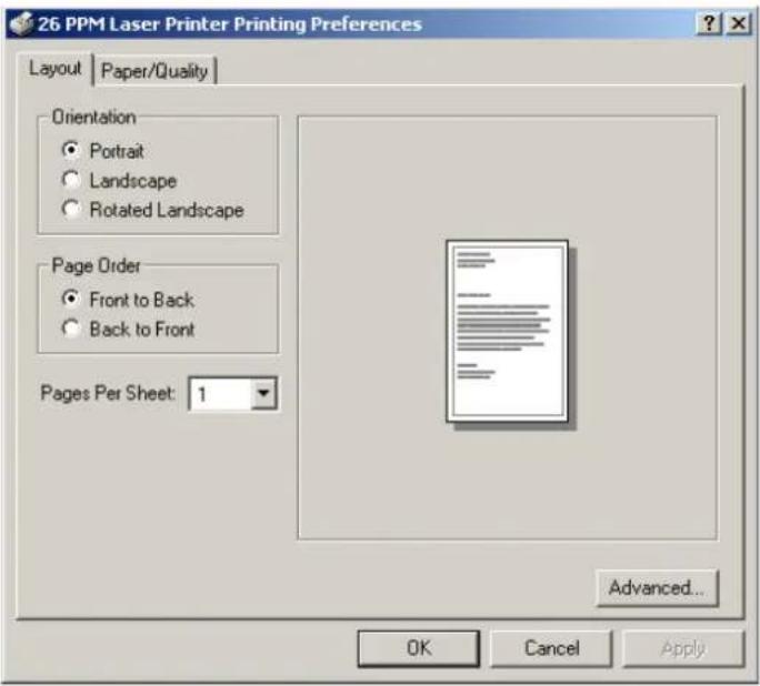
- Click on the Copy Count button to enter the number of copies and make sure the Collate button is checked.
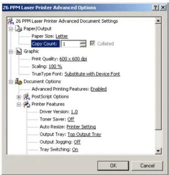
- Click to OKAY button and your printer driver is set to collate the number of copies specified.
Saved Jobs Feature
You can create saved jobs using the drivers that support this feature. The drivers that support this feature are as follows:
• PCL - All windows platforms
- PostScript - Windows 2000 and Windows XP
There are three job types available, Normal, Saved, and Private. The descriptions of the job types are as follows:
Normal
A normal print job. No print job data is saved.
Saved
The print job data is saved on the Hard Disk or User Flash Option. The job will be saved in the "Job Library" folder. A sub-folder in the Job Library folder will be created, if necessary, for the user, as specified by the user name. The print job will be stored in a file in this folder with a name created by the user in the job name field of the printer driver.
Private
The print job data is saved on the Hard Disk or User Flash Option. The job will be saved in the "Job Library" folder. A sub-folder will be created, or the by the user as specified by user name. The print job will be stored in a file in this folder, with a name specified by user in the job name field of the printer driver. "Private" print job files are secured by having an associated PIN which is entered in the PIN field of the driver by the user. Any access to this file will require the PIN to be entered.
To access the Saved Jobs on your desktop, go to the Start menu, left click on Settings, left click on Printers, and then click on your printer driver icon, right click and follow the menu to the Properties menu.
- You are now in the Printing Properties menu, click on the Printing Preference button.

- Click on the Advanced button.
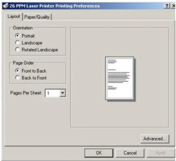
- Now scroll down to the Job Type Section of the menu.

- When you click on Job Type, three job types are available. Normal, Saved, and Private. The default setting is Normal.

- If you want to Save your print job, select Save in the Job Type Menu and enter a name you want to save the job as and it will be saved under the User ID folder listed. You can change the User ID in this menu also.
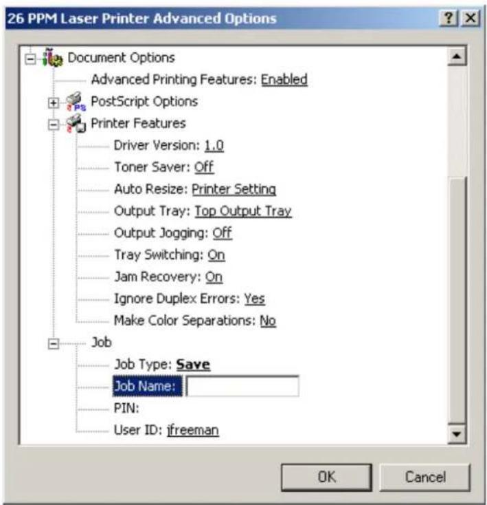
- If you want to make your job Private, you select Private and enter the Job name to save it.

- Then you enter a four digit number in the PIN menu. You will only be able to print this document if you know the PIN number

Working with Saved Jobs
There are two ways to work with Saved Jobs. One is through the front panel menus, the other is through the printer web pages.
NOTE: Please see "Accessing the Printer Web Page" on page 10-33 to learn how to access the Job Library features through the web page.
Front Panel Access
The Job Library Menu provides access to the printer settings that are related to the optional Hard Disk. Use the following procedure to enter the Job Library Menu to Print or Delete jobs that are Saved in the Job Library, including jobs that have a PIN number:
- Press the MENU button on the control panel.
- Press the NEXT button until the text "Job Library Menu" is shown on the second line of the display.
- Press the SELECT button to enter the Job Library Menu.
- Press the NEXT button to move through the submenus: Print or Delete.
- Press the SELECT button to enter a submenu.
Use the procedures in the following table to access and change the system settings.
| Menu Submenus Procedure for Changing Setting | ||
| Job Library(Saved Job) | Print(To print a saved job) | 1. Press NEXT or PREVIOUS to scroll through Print or Delete options.2. Press SELECT to choose Print. |
| PrintUser Folder 1 | 1. Press NEXT or PREVIOUS to scroll through the User Folder Names.2. Press SELECT to choose the desired User Folder. | |
| PrintJob1 | 1. Press NEXT or PREVIOUS to scroll through the Print Job Names.2. Press SELECT to choose the desired Print Job. | |
| Job NameCopies - Select 1-99 | 1. Press NEXT or PREVIOUS to increase or decrease each digit of the two-digit number.2. Press SELECT set one digit and move to the next digit.3. Press SELECT after changing the last digit to save this setting. | |
| Job NameCopies | 1. Press SELECT to print the job. | |
| PrintingPlayback | 1. The printer will display PRINTING on Line 1 and PLAYBACK on Line 2 of the display while printing the job. | |
| Job Library(Saved Job with PIN) | Print(To print a saved job with a PIN) | 1. Press NEXT or PREVIOUS to scroll through Print or Delete options.2. Press SELECT to choose Print. |
| PrintUser Folder 1 | 1. Press NEXT or PREVIOUS to scroll through the User Folder Names.2. Press SELECT to choose the desired User Folder. | |
| PrintJob1 | 1. Press NEXT or PREVIOUS to scroll through the Print Job Names.2. Press SELECT to choose the desired Print Job. | |
| job NamePIN | 1. Press NEXT or PREVIOUS to increase or decrease each digit of the four-digit number.2. Press SELECT to set one digit and move to the next digit.3. Press SELECT after changing the last digit to save this setting. | |
| job NameINCORRECT PIN | 1. If an incorrect PIN is entered, press PREVIOUS to re-enter the correct PIN. | |
| job NameCopies - Select 1-99 | 1. Press NEXT or PREVIOUS to increase or decrease each digit of the two-digit number.2. Press SELECT to set one digit and move to the next digit.3. Press SELECT after changing the last digit to save this setting. | |
| Menu Submenus | Procedure for Changing Setting | |
| Job NameCopies | 1. Press SELECT to print the job. | |
| PrintingPlayback | The printer will display PRINTING on Line 1 and PLAYBACK on Line 2 of the display while printing the job. | |
| Job LibraryDELETE | Delete(To delete a saved job) | 1. Press NEXT or PREVIOUS to scroll through Print or Delete options.2. Press SELECT to choose Delete. |
| DeleteUser Folder 1 | 1. Press NEXT or PREVIOUS to scroll through the User Folder Names.2. Press SELECT to choose the desired User Folder. | |
| DeleteJob1 | 1. Press NEXT or PREVIOUS to scroll through the Print Job Names.2. Press SELECT to choose the desired Print Job to Delete. | |
| Job Library(Delete SavedJob with PIN) | Delete(To delete a saved job with a PIN) | 1. Press NEXT or PREVIOUS to scroll through Print or Delete options.2. Press SELECT to choose Delete. |
| DeleteUser Folder 1 | 1. Press NEXT or PREVIOUS to scroll through the User Folder Names.2. Press SELECT to choose the desired User Folder. | |
| DeleteJob1 | 1. Press NEXT or PREVIOUS to scroll through the Print Job Names.2. Press SELECT to choose the desired Print Job to Delete. | |
| Job NamePIN | 1. Press NEXT or PREVIOUS to increase or decrease each digit of the four-digit number.2. Press SELECT to set one digit and move to the next digit.3. Press SELECT after changing the last digit to save this setting. | |
| Job NameINCORRECT PIN | 1. If an incorrect PIN is entered, press PREVIOUS to re-enter the correct PIN. | |
| Job Name 1. Press SELECT to Delete the job. | ||
Job Accounting Feature
The printer supports a job accounting feature which will store certain information about each print job received by the printer. There are two ways to work with this feature. One is through the front panel menu.
NOTE: Please see "Accessing the Printer Web Page" on page 10-33 for more information on the Job Accounting Feature.
Front Panel Access
The Job Accounting Menu provides access to functions and settings related to this feature. Use the following procedure to enter the Job Accounting Menu to change the settings or access the functions:
- Press the MENU button on the control panel.
- Press the NEXT button until the text "Job Accounting Menu" is shown on the second line of the display.
- Press the SELECT button to enter the Job Accounting Menu.
- Press the NEXT button to move through the submenus: Enable, Print Info, Reset Info.
- Press the SELECT button to enter a submenu.
Use the procedures in the following table to access and change the system settings.
| SubMenu Settings | Procedure for Changing Setting | |
| ENABLED Yes or | No 1. Press NEXT or PREVIOUS to scroll through Yes or No options.2. Press SELECT to choose Yes to turn on this function. | |
| PRINT INFO 1. | Press SELECT to begin printing the Job AccountingSummary Report. | |
| RESET INFO 1. | Press SELECT to reset the Job AccountingInformation. This will delete all stored information related to jobs received by the printer. | |
When you print a Job Accounting Summary the following information will print on your report:
| Job Name | User Name | Port Protocol | Pages | (sides) | Pages (sheets) | Date/Time | Duration |
| job2 | jerry | parallel | 4 | 4 | March 30 200401:11:10 PM | 00:00:08 | |
| job1 | jerry | network1 | LPD | 4 | 4 | March 30 200401:12:10 PM | 00:00:04 |
| job3 | user1 | network1 | Ethertalk | 3 | 3 | March 30 200401:15:10 PM | 00:00:03 |
NOTE: Only products that have real time clock support will provide the Date/Time information.
Using the Custom Paper Size Feature
There are two ways to work with the Custom Paper Size Feature. One is through the front panel menus, the other is through the printer driver. If you have a Windows or Macintosh printer driver, you can access this feature from the driver and you do not have to use front panel settings. Use the front panel access to these features if you have a Unix system or do not have Windows or Macintosh drivers.
Operator Panel Access
The Paper Menu provides access to the Custom Paper Size settings. The range for setting a custom paper size is:
Paper Width 3.5 inches minimum to 8.5 inches maximum
Paper Length 5.5 inches minimum to 35.45 inches maximum
Use the following procedure to enter the Paper Menu to set a Custom Paper Size:
- Press the MENU button on the control panel.
- Press the NEXT button until the text "Paper Menu" is shown on the second line of the display.
- Press the SELECT button to enter the Paper Menu.
- Press the NEXT button until the text "Media Size/Type is shown on the second line of the display and press the SELECT button.
- Press the NEXT button until the text "MBF" is shown on the second line of the display.
- Press the SELECT button.
- Press the NEXT button until the text "Custom Size" is shown on the second line of the display.
- Press the SELECT button to enter the "Custom Size" menu. "Width" is shown on the second line of the display.
- Press NEXT or PREVIOUS to increase or decrease each digit of the three-digit number to set the width of your paper. When the width of paper is correct, press the SELECT button.
- Next "Length" is shown on the second line of the display.
- Press NEXT or PREVIOUS to increase or decrease each digit of the three-digit number to set the length of your paper. When the length of paper is correct, press the SELECT button.
- Press RETURN until you exit out of all the submenus and return to READY.
Printer Driver Access
To access the Custom Paper Size Feature through your printer driver, use the following procedure:
- On your desktop, go to the Start menu, left click on Settings, left click on Printers, and then click on your printer driver icon, right click and follow the menu to the Properties menu.
- You are now in the Printing Properties menu, click on the Printing Preference button.

- Click on the Advanced button.
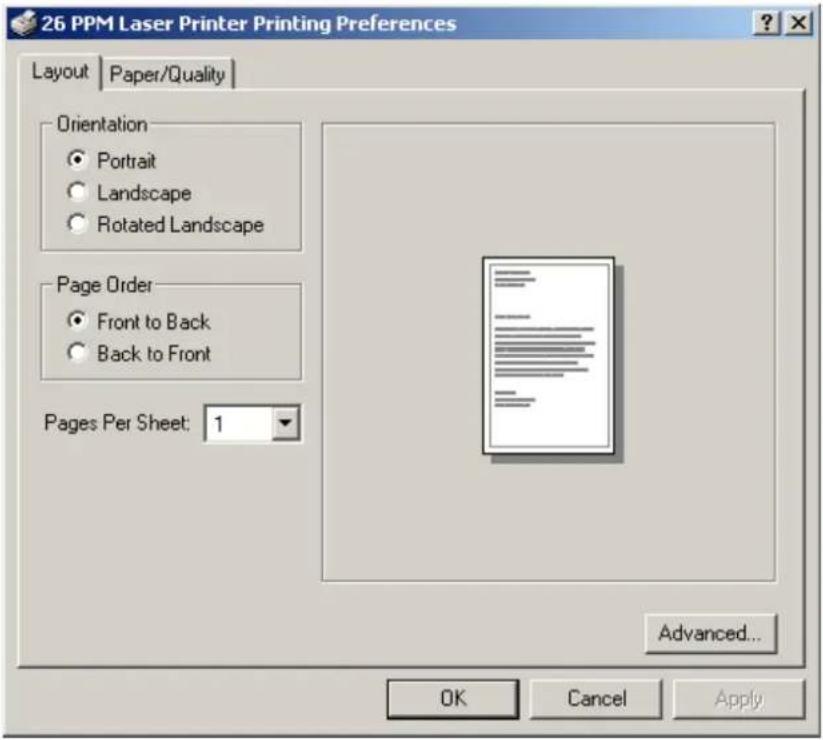
- Click on the Paper Size button.

- Scroll down to Custom Page Size and click.

- Then enter the width and height of your custom paper size.

- Click the OKAY button until you exit out of the driver menu. You are now ready to print your custom sized document.
Custom Page size and Microsoft Word, Word 2000, and Word 2003
When you specify a PostScript custom page size in the Paper Size box in the advanced printer properties for a supported printer, the custom size setting appears to be ignored if you have configured Microsoft Word to use the PostScript Custom Page Size setting. Word defaults to the default size of 8.5 by 11 inches.
Resolution
If you want to use PostScript custom page sizes that are supported by a printer, the only way to make them work correctly in Word is to add custom forms to Windows and then to choose those form names in Word. By using this method, the PostScript Page Size setting in Word is ignored, and the newly added forms are used instead.
Create a custom form for printing to a non-standard paper size in Microsoft Windows NT 4.0, Windows 2000, and Windows XP.
To create a custom form, follow these steps:
- Navigate to CONTROL PANEL, double click PRINTERS.
■ On the FILE menu, click SERVER PROPERTIES.
■ On the FORMS tab, select the CREATE A NEW FORM check box.
Enter the settings for the new form.
NOTE: When you set up a custom form, the margins cannot go beyond the confines of the specifications for the installed printer driver. Printable regions must be adhered to with regard to margin limits for the printer and driver in use.
■ Click SAVE FORM or OK
To use the new form as the default form, follow these steps:
WINDOWS NT
■ In CONTROL PANEL, double-click PRINTERS.
■ Right-click the printer you want to select, and then click DOCUMENT DEFAULTS.
■ In the PAPER SIZE box, click the new form.
- Click OK.
WINDOWS 2000 AND XP
■ In CONTROL PANEL, double-click PRINTERS.
■ Right-click the printer you want to select and then click PROPERTIES.
■ On the GENERAL tab, click PREFERENCES.
- On the PAPER QUALITY tab, click ADVANCED, and then in the PAPER SIZE drop down menu, select the custom form size.
- Click OK.
To use the new form from a program, follow these steps:
■ In the program, click PRINT.
■ In the PRINT dialog box, click PROPERTIES.
■ In the PAPER SIZE box, click the new form.
- Click OK.
- Click OK to print.
NOTE: New forms are stored on the computer where they are created. When you create a new form for use with a shared printer, create the form on the print server.
NOTE: On a Windows 2000 and XP computer, occasionally the newly created form will not appear in the drop down list under paper size. If you encounter this, you may need to select an existing form under server properties, modify the settings, check box to create a new form, change the form name and save the form. Once you save the form, it should appear in the paper size drop down box.
Accessing the Printer Web Page
You can access the printer web page by going to the internet browser and typing the IP address of your network printer (http://IP ADDRESS). You can directly access the printer control panel on the web and it allows you to view and change the printer settings. Following is an example of the printer web page:
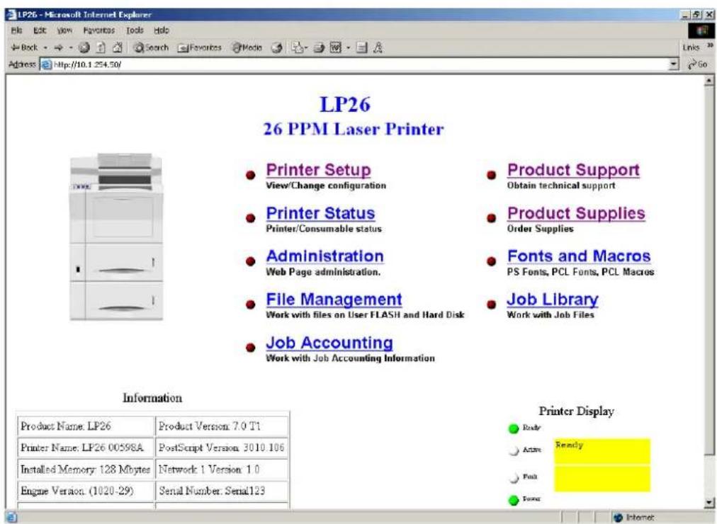
When you access the printer web page it will display your printer name and logo and provide access to the following menus:
| Main Page of Printer Web Site | Submenu 1 of Printer Web Site | Submenu 2 of Printer Web Site |
| Printer SetupYou can view and change printer configuration. With access to the following menus: | Paper MenuProvides access to the printer settings for various paper-handling functions: | CopiesDuplexDuplex BindDefault SourceManual FeedOutput TrayMedia Size/TypeTray LinkingJob OffsetBlank PagesFace Up InstMBF FirstAuto ResizeSeparator PageCustom Size Unit |
| Interface MenuProvides access to the printer interface settings: | PortParallelNetwork 1Parallel SetupInterpreterFormatModeDelay Out CloseNetwork 1SetupInterpreterFormatNetwork AddressIP AddressSubnet MaskDefault RouterLPD BannerDHCPDelay Out CloseHost NamemDNS Host NancmDNS Svc NameMulti-SessionAppleTalkBinary PS | |
| PS MenuProvides access to the PostScript settings: | Print PS ErrorsManual Feed TO | |
| PCL MenuProvides access to the PCL settings: | OrientationFont SourceFont NumberPitch or Point SizeSymbol SetMacro FilterLines Per PageCR ModeLF ModeFF ModePrint AreaParameter ValuesPaper SourcePaper Size | |
| System MenuProvides access to the system settings: | Display LanguageAlarm ControlPower SaverWait TimeoutJob TimeoutJam RecoveryHex PrintToner OutPage CompressionIntellifilter | |
| Quality MenuProvides access to the printer settings that are related to print quality: | Print DensityToner Saver | |
| Printer StatusDisplays printer option and consumables status. You can view the current settings for the Input options on your printer and the Output options installed. | Email SetupProvides access to the following settings which allow the administrator to set parameters for specific conditions and have an email alert sent to specific addresses. | Email Server Settings:SMTP Server IP AddressEnable AuthenticationUser Name: (for Authentication)Password: (for Authentication)Printer Email AddressReply-To-AddressEmail Address Settings:Example:jsmith@abc_co.comEmail Alert Conditions:Re-send IntervalOff LineConsumablesToner Low/Toner OutPaper Low/Paper OutPaper JamCover OpenStacker ErrorMass Storage ErrorRecoverable ErrorService Call RequiredEmail Signature Settings |
| Input Displays paper trays and the paper size, type and capacity levels of all installed trays and options. | ||
| Output Displays output paper trays and capacity level. | ||
| Consumable Information Displays all toner cartridge percentage used. Also displays the Toner Page Count and Drum Time. | ||
| Other Sheet Counter | Image Counter | |
| AdministrationDisplays security and factory defaults. Allows you to set up support and supplies web links. | ||
| Factory Defaults | ||
| Console Security | ||
| Refresh Rate | ||
| Support Link | ||
| Supplies Link | ||
| Admin. Name | ||
| Password | ||
| Confirm Password | ||
| File Management*Allows you to access (print or delete) files stored on your Hard Disk or User Flash. | ||
| Only appears if User Flash is installed. | User Flash Files You can view contents of folder, retrieve files or delete print files. | |
| Format User Flash Allows you to format your User Flash. | ||
| Print User Flash Summary Prints a summary page of the files stored in the User Flash. | ||
| Only appears if Hard Disk Option is Installed. | Hard Disk Files You can view contents of folder, retrieve files or delete print files. | |
| Format Hard Disk Allows you to format your Hard Disk. | ||
| Print Disk Summary Prints a summary page of the files stored on the Hard Disk. | ||
| Job Accounting*View, retrieve, or reset job accounting information. | ||
| Enable/Disable Click Yes or No to Enable or Disable Job Accounting | ||
| Retrieve Job Accounting File Retrieve a job file and upload the file information to a CSV file. | ||
| Display Job Accounting Info Displays all job information such as job name, user name, port, protocol, pages, date/time and duration. | ||
| Reset All Job Accounting Info Deletes all stored Job Accounting information. | ||
| Product SupportDirect link to obtain technical support | Takes you to the Product Support Website where you can obtain technical support. | |
| Product SuppliesDirect link to order supplies | Takes you to the Product Supplies Website where you can order product supplies. | |
| Fonts and Macros*Allows you to view the PostScript Fonts and PCL Fonts, stored internally on your printer. Also allows you to view Macros stored on your Hard Disk or User Flash Options. | PS FontsPCL FontsMacros | |
| Job Library*Takes you to the job library where you can view all user folders and print jobs. Also allows access to print or delete all files stored in your job library on your Hard Disk or User Flash Option. | View contents of user folder.Retrieve files.Delete or print selected files. | |
NOTE: *These menus only appear if you have a Hard Disk or User Flash Option installed.
Following are a few examples of how to use the printer web page.
Printer Setup
Go to your web browser and type in your printer web address. The printer web page will appear.
1. Click on Printer Setup

- When you enter the Printer Setup Menu, you have access to the Paper Menu, Interface Menu, PS Menu, PCL Menu, System Menu, Quality Menu and Email Setup.

- The Paper Menu allows the user to access and change the paper menu settings.

- The Interface Menu allows the user to access and change the interface settings.
![Port Parallel C (C0) * (C0) Parallel Setup Delay Out Close R (OB) * (On) Network 1 Setup IP Address 010.001.254.050 Network 1 Setup Delay Out Close R (OB) * (On) Network 1 Setup mDNS Host Name JP080098A Network 1 Setup mDNS Host Name JP080098A Network 1 Setup Binary PS R (OB) * (On) Network 1 Setup Factory Defaults [ ]](/content/2026/05/1054084/images/5babd0aed8eefe27cdc6be2efba17426fe0a31af09efca96bd569f1f1f9f5c41.jpg)
- The PS Menu allows the user to access and change the Post Script Menu settings

- The PCL Menu allows the user to access and change the PCL settings
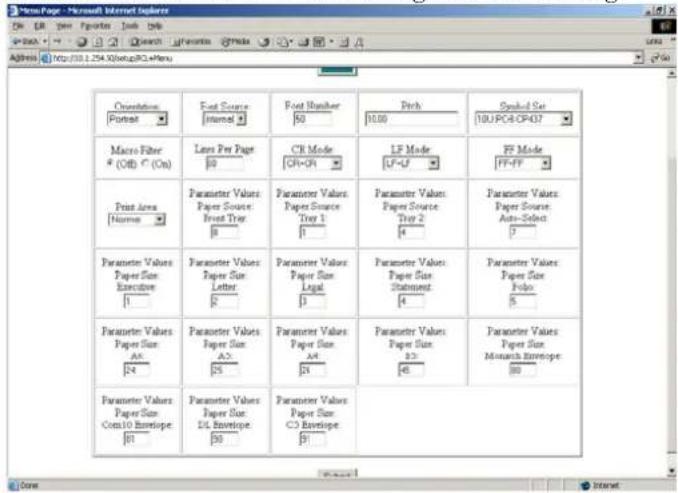
- The System Menu allows the user to access and change the System Menu settings
![LP26 26 PPM Laser Printer System Menu Display Language [English] Power Save [5] Wait Timeout [5] Job Timeout [8] Jan Recovery C (Off) R (On) Hot Print R (Off) C (On) Toner Low Continuous Reset Tone Life R (No) C (Trt) Interfilter C (Off) R (On) Submit](/content/2026/05/1054084/images/57934f5b675f46da3e2d5efce416eb237ba56ebfb01e4626e8603468fdb9ea40.jpg)
- The Quality Menu allows the user to access and change the Quality Menu settings
![New Page - Microsoft Internet Explorer File Edit View Favorites Tools Help on Back Search Favorites Media Address http://10.1.254.SolventQuality=Menu LP26 26 PPM Laser Printer Quality Menu Resolution [000 dpi] Timer Save: R (CIF) C (On) Text Density 5 Submit](/content/2026/05/1054084/images/6f9fd92efa03c6434150918e571cf13ac9fc6a978935e2e52c55510d0615cd7a.jpg)
- The Email Setup Menu allows you to configure the printer to send email messages when certain status conditions occur.
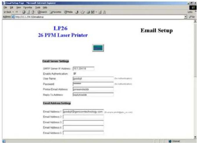

Email Server Settings
-
SMTP Server IP Address: Enter the IP address for the SMTP server that the printer will use to transmit the email messages.
-
Enable Authentication: Check this box if the SMTP server requires authentication.
-
User Name: (for Authentication) Enter the name of a user who is authorized to access the SMTP servcr.
-
Password: (for Authentication) Enter the password for the user who is authorized to access the SMTP server.
-
Printer Email Address: The character string configured here will be used in the "FROM" field of the email message.
-
Reply-To-Address: The character string configured here will be used in the "REPLY TO" field of the email message.
Email Address Settings/Email Alert Conditions
You can configure 1 - 5 destination email addresses. For each of these destination email addresses you can configure which status conditions will cause an email to be sent. In addition, a resend interval can be set for each address, which determines if or how often the email message should be resent, as long as the condition persists.
Email Signature Settings
These are text strings that are appended to the end of the email messages. They can be used to provide helpful hints/reminders to reccprients of the status email messages.
Job Accounting
Web Page Access
Go to your web browser and type in your printer web address. The printer web page will appear.
1. Click on Job Accounting.
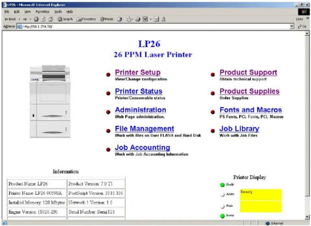
- When you enter the Job Accounting field the following options appear:

- When you click on Enable/Disable it will take you to the following screen. Click Yes or No to Enable or Disable Job Accounting.

- When you click on Retrieve Accounting Files it will upload the file information, which is stored in a .CSV file.
| A | B | C | D | E | F | G | H | I | J | K | L | M | N | ||
| 1 | Job Name | User Name | Pod | Protocol | Pages (and Pages) (sh Date/Time Duration | ||||||||||
| 2 | job1 | jerry | Parallel | 4 | 4 April 27 20 | 0:00.05 | |||||||||
| 3 | job2 | jerry | Parallel | 4 | 4 April 27 20 | 0:00.14 | |||||||||
| 4 | job5 | jerry | Network1 | AppSocket | 8 | 8 April 27 20 | 0:01.41 | ||||||||
| 5 | job5 | jerry | Network1 | AppSocket | 6 | 8 April 27 20 | 0:01.41 | ||||||||
| 6 | job5 | jerry | Network1 | AppSocket | 6 | 8 April 27 20 | 0:01.41 | ||||||||
| 7 | job5 | jerry | Network1 | AppSocket | 6 | 8 April 27 20 | 0:01.41 | ||||||||
| 8 | job5 | jerry | Network1 | AppSocket | 6 | 8 April 27 20 | 0:00.06 | ||||||||
| 9 | job5 | jerry | Network1 | AppSocket | 6 | 8 April 27 20 | 0:00.05 | ||||||||
| 10 | job5 | jerry | Network1 | AppSocket | 6 | 8 April 27 20 | 0:01.35 | ||||||||
| 11 | job5 | jerry | Network1 | AppSocket | 6 | 8 April 27 20 | 0:01.41 | ||||||||
| 12 | job5 | jerry | Network1 | AppSocket | 6 | 8 April 27 20 | 0:01.40 | ||||||||
| 13 | job5 | jerry | Network1 | AppSocket | 6 | 8 April 27 20 | 0:01.41 | ||||||||
| 14 | job5 | jerry | Network1 | AppSocket | 6 | 8 April 27 20 | 0:01.40 | ||||||||
| 15 | job5 | jerry | Network1 | AppSocket | 6 | 8 April 27 20 | 0:00.05 | ||||||||
| 16 | job5 | jerry | Network1 | AppSocket | 6 | 8 April 27 20 | 0:00.05 | ||||||||
| 17 | job5 | jerry | Network1 | AppSocket | 6 | 8 April 27 20 | 0:00.06 | ||||||||
| 18 | job5 | jerry | Network1 | AppSocket | 6 | 8 April 27 20 | 0:00.06 | ||||||||
| 19 | job5 | jerry | Network1 | AppSocket | 6 | 8 April 27 20 | 0:00.06 | ||||||||
| 20 | job5 | jerry | Network1 | AppSocket | 6 | 8 April 27 20 | 0:00.06 | ||||||||
| 21 | job5 | jerry | Network1 | AppSocket | 6 | 8 April 27 20 0:00.06 | |||||||||
| 22. job5 | |||||||||||||||
- When you click on Display Job Accounting Info it will bring you the following screen which displays all your job information.

NOTE: Only products that have real time clock support will provide the Date/Time information.
- When you click on Reset All Job Accounting Info, all printer job information will be deleted.
File Management
Web Page Access
Using the printer web page, you can delete, print, or download any job files stored in the job library. Go to your web browser and type in your printer web address. The printer web page will appear as follows:
1. Click on Job Library.

- Click on the folder icon or name to view the printer jobs in the user folders.

- The printer job information will appear. If there is a PIN number associated with the file, you will be required to enter the correct PIN number to access the print file.
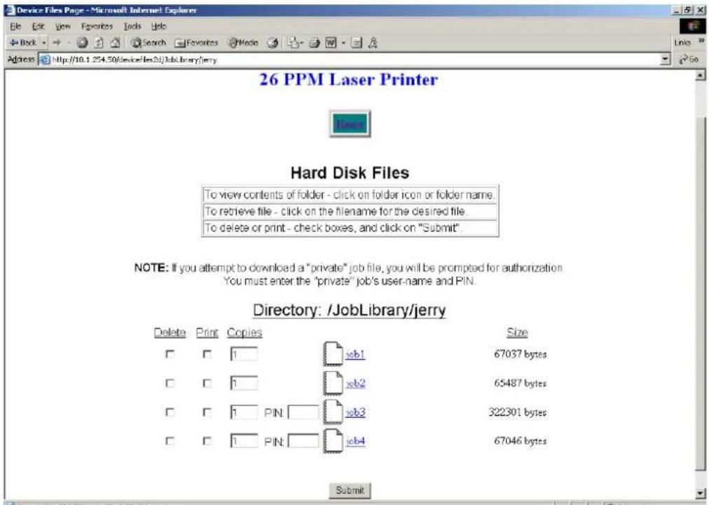
Using the RS-232C/RS-422 Serial Interface
This section lists the Serial Interface setup features and available selections via the control panel menus. The Serial Interface connector pinouts are listed. Troubleshooting error messages appearing on the printer's control panel are also discussed.
Control Panel MENU structure
When the RS-232C/RS-422 serial interface is installed, the printer control panel menu structure is enhanced as shown in the following table. The shaded areas denote additional features and settings relevant to the RS-232C/RS-422 interface.
| Menu | ||||
| Paper Menu | ||||
| Interface Menu | ||||
| Port | ||||
| Parallel | ||||
| Serial | ||||
| Parallel Setup On | ||||
| Serial Setup Off | ||||
| Interpreter | ||||
| Auto Switch | ||||
| PCL | ||||
| Postscript 3 | ||||
| Format | ||||
| Normal | ||||
| Binary | ||||
| Raw | ||||
| Serial Mode | ||||
| RS232 | ||||
| RS422 | ||||
| Baud Rate | ||||
| 1200 | ||||
| 2400 | ||||
| 4800 | ||||
| 9600 | ||||
| 19200 | ||||
| 38400 | ||||
| 57600 | ||||
| 115200 | ||||
| Data Bits | ||||
| 7 | ||||
| 8 | ||||
| Stop Bits | ||||
| 1 | ||||
| 2 | ||||
| Parity | ||||
| None | ||||
| Even | ||||
| Odd | ||||
| DTR Ready/Busy | ||||
| On | ||||
| Off | ||||
| DTR Onl/Offl | ||||
| On | ||||
| Off | ||||
| DTR Error | ||||
| On | ||||
| Off | ||||
| RTS Ready/Busy | ||||
| On | ||||
| Off | ||||
| RTS Onl/Offl | ||||
| On | ||||
| Off | ||||
| RTS Error | ||||
| On | ||||
| Off | ||||
| XON Ready/Busy | ||||
| On | ||||
| Off | ||||
| XON Onl/Offl | ||||
| On | ||||
| Off | ||||
| XON Error | ||||
| On | ||||
| Off | ||||
| DTR Polarity | ||||
| High | ||||
| Low | ||||
| RTS Polarity | ||||
| High | ||||
| Low | ||||
| Robust XON | ||||
| On | ||||
| Off | ||||
| PS Menu | ||||
| PCL Menu | ||||
| System Menu |
NOTE: The structure of your display menus may vary slightly depending on the options installed in your printer.
SERIAL SETUP Menu
The following selections becomes available within a SERIAL SETUP submenu of the INTERFACE menu when the RS-232C/RS-422 serial interface is installed.
Interpreter
| AVAILABLE SELECTIONS Auto Switch | PCLPostscript 3 |
| DEFAULT Auto Switch |
Format
| AVAILABLE SELECTIONS Normal | BinaryRaw |
| DEFAULT Raw |
Serial Mode
| AVAILABLE SELECTIONS RS232 | RS422 |
| DEFAULT RS232 |
Baud Rate
| AVAILABLE SELECTIONS 1200 | 240048009600192003840057600115200 |
| DEFAULT 9600 |
Data Bits
| AVAILABLE SELECTIONS 7 | 8 |
| DEFAULT 8 |
Stop Bits
| AVAILABLE SELECTIONS 1 | 2 |
| DEFAULT 1 |
Parity
| AVAILABLE SELECTIONS None | EvenOdd |
| DEFAULT None |
DTR Ready/Busy
| AVAILABLE SELECTIONS Off | On |
| DEFAULT Off |
DTR On/Off
| AVAILABLE SELECTIONS Off | On |
| DEFAULT Off |
DTR Error
| AVAILABLE SELECTIONS Off | On |
| DEFAULT Off |
RTS Ready/Busy
| AVAILABLE SELECTIONS Off | On |
| DEFAULT Off |
RTS On/Off
| AVAILABLE SELECTIONS Off | On |
| DEFAULT Off |
RTS Error
| AVAILABLE SELECTIONS Off | On |
| DEFAULT Off |
XON Ready/Busy
| AVAILABLE SELECTIONS Off | On |
| DEFAULT On |
XON On/Off
| AVAILABLE SELECTIONS Off | On |
| DEFAULT On |
XON Error
| AVAILABLE SELECTIONS Off | On |
| DEFAULT Off |
DTR Polarity
| AVAILABLE SELECTIONS High | Low |
| DEFAULT High |
RTS Polarity
| AVAILABLE SELECTIONS High | Low |
| DEFAULT High |
Robust XON
| AVAILABLE SELECTIONS Off | On |
| DEFAULT Off |
Disabling the Serial Interface
The following selection becomes available within the PORT submenu of the INTERFACE menu when the RS-232C/RS-422 serial interface is installed.
Serial
The Serial option enables you to turn off the serial port on the interface. This selections is often used to permit uninterrupted communication to other ports such as the parallel or other network ports.
| AVAILABLE SELECTIONS On | Off |
| DEFAULT On |
References for OpenVMS users
You can print to your laser printer via the serial interface option from an OpenVMS system, either directly connected to the system or through a network device such as a terminal server.
It is recommended that DECprint Supervisor (DCPS) be used for printing. Please see the “Setting Up Printers” chapter of the DCPS System Manager's manual for information on creating a DCPS print queue.
If DCPS will not be used, please see the “Setting Up and Maintaining Queues” chapter of the OpenVMS System Manager's manual for information on setting up print queues using the Open-VMS print symbiont.
RS-232C Serial Cable Pin Assignments
Eight pins of the 25-pin serial cable are utilized for the RS-232C standard:
| Pin No. | Signal Direction Description | ||||||
| 1 | G | N | D | F | r | a | m |
| 2 | T | X | D | O | u | t | T |
| 3 | R | X | D | I | n | R | e |
| 4 | R | T | S | R | e | q | u |
| 5 | C | T | S | I | n | C | I |
| 6 | D | S | R | I | n | D | a |
| 7 | GND | Logic Ground | |||||
| 20 | DTR | Out | Data Terminal Ready | ||||
RS-422 Serial Cable Pin Assignments
Five pins of the 25-pin serial cable are utilized for the RS-422 standard:
| Pin No. | Signal Direction Description | ||||||
| 1 | G | N | D | F | r | a | m |
| 15 | RXD - | In | Receive Data + | ||||
| 17 | RXD + | In | Receive Data - | ||||
| 19 | TXD - | Out | Transmit Data - | ||||
| 25 | TXD + | Out | Transmit Data + | ||||
Troubleshooting
This section discusses troubleshooting error messages appearing on the printer's control panel. Sources of help, information and technical support are also discussed.
Control Panel Error Messages
The format of control panel error messages is:
NETx: ERROR y
and where x indicates the network slot where the serial interface is installed and where y reflects the error number as shown below:
| Error No. | Description Action Required | |
| 1 | Overrun Error Verify that all DTS, RTS and XON settings within the SERIAL SETUP menu are configured correctly. Check the pinout assignments of cabling between the printer and the host. | |
| 2 | Parity Error Verify that the PARITY setting within the SERIAL SETUP menu is configured correctly. Check the pinout assignments of cabling between the printer and the host. | |
| 3 | Framing Error Verify that the SERIAL MODE, BAUD RATE, DATA BITS, STOP BITS and PARITY settings within the SERIAL SETUP menu are configured correctly. | |
| 4 | Flow Control Error Verify that all DTS, RTS and XON settings within the SERIAL SETUP menu are configured correctly. Check the pinout assignments of cabling between the printer and the host. | |
Example
An error message of:
NET2: ERROR3
indicates that the serial interface which is located in network slot 2 has experienced a framing error.
Obtaining Help and Information
Several sources of help and information are available, depending on the type of help you need:
Your Point of Purchase
Your local vendor from whom you purchased this printer may be best equipped to help you. Your vendor has specially trained service technicians available to answer questions and the equipment to analyze your printer problems.
Your Application Vendor
Often, “printing” problems have more to do with the application being used than with the printer. In this case, the application manufacture is the best source of help.
Technical Support
Technical Support is available world-wide. Please refer to your point of purchase for the appropriate contact in your area.
When calling for assistance, please have the following information readily available:
■ Your phone number, fax number and shipping address.
■ A description of the problem.
■ The printer model.
■ The type of host computer you are using.

Appendix A
Customer Support and Part Numbers
In this Chapter . . .
- "About this Chapter" on page A-2
- "Obtaining Help and Information" on page A-2
• “Technical Support” on page A-2
• "TallyGenicom Worldwide Offices" on page A-3
• "TallyGenicom Part Numbers" on page A-4
About this Chapter
This chapter discusses sources of help, information and technical support.
Obtaining Help and Information
Several sources of help and information are available, depending on the type of help you need:
Your Point of Purchase
Your local vendor from whom you purchased this printer may be best equipped to help you. Your vendor has specially trained service technicians available to answer questions and the equipment to analyze your printer problems.
Your Application Vendor
Often, “printing” problems have more to do with the application being used than with the printer. In this case, the application manufacture is the best source of help.
Technical Support
Internet
The TallyGenicom server provides access to technical reports, new product announcements, trade show schedule, and other general information about TallyGenicom. Many support features are available through the web site, including support by e-mail and technical documents. You can access the TallyGenicom world wide web server via any one of the many world-wide web browsers available to Internet users. The TallyGenicom home page is at http://www.TallyGenicom.com.
TallyGenicom Technical Support
TallyGenicom North America: Phone 425-251-5532 for call-back service Monday through Friday: 6:00 AM to 4:30 PM PST/PDT. Please be aware that our peak activity times are between 11:00AM and 2:00PM. Calling outside of this time frame may result in quicker access to one of our representatives.
Technical Support is available world-wide. Please refer to your point of purchase for the appropriate contact in your area.
When calling for assistance, please have the following information readily available:
- Your phone number, fax number and shipping address.
• A description of the problem. - The printer model.
• The type of host computer you are using. - The type and version of operating system you are using.
• The application and version you are using. - The interface you are using (e.g., network, parallel, serial).
- If using the network interface, the network protocol (TCP/IP, EtherTalk, IPX/SPX).
-
The printer emulation you are using (e.g., PCL or PostScript).
-
A printout of your printer's Configuration Summary. (Refer to your printer's Installation Guide).
- If you have a printer hardware problem you cannot resolve, provide the error message displayed on the Control Panel. For a list of error messages, refer to your printer's User manual.
TallyGenicom Worldwide Offices
The following table lists TallyGenicom offices worldwide:
| TallyGenicom United States | |
| TallyGenicom LLCCorporate Headquarters | TallyGenicom4500 Daly Drive, Suite 100Chantilly, VA 20151Telephone: 703-633-8700Fax: 703-222-7630 |
| Document Solutions(Printer Products) | Document SolutionsOne Solutions WayWaynesboro, VA 22980-1999Telephone: 800-436-4266 or 540-949-1000Fax: 540-949-1392 |
TallyGenicom Part Numbers
The following tables list TallyGenicom part numbers for the Intelliprint mL260 printer, options, and consumables.
Printers
| TallyGenicom Part Number Description | |
| ML260N-CA 110V ML260 Laser | Printer, Ethernet, US |
| ML260N-CC 220V ML260 Laser | Printer, Ethernet, Central Europe |
Paper Handling Options
| TallyGenicom Part Number Description | |
| ML260X-DA ML260 Duplexer | |
| ML260F-TA ML260 550-Sheet Feeder w/Universal Paper Tray | |
| ML260F-TE ML260 Envelope Feeder | |
| ML260F-TB ML260 500 Sheet Offset Catch Tray | |
Network Interfaces
| TallyGenicom Part Number Description | |
| MLXXXF-SI RS-232C/422 Serial Option | |
| ML402N-EI Ethernet/IPDS | |
DRAM, FLASH SIMM and Hard Disk Drive Options
| TallyGenicom Part Number Description | |
| MLXXXM-64 64MB Memory DIMM | |
| MLXXXM-128 128MB Memory DIMM | |
| MLXXXF-FP 16MB User FLASH DIMM | |
| MLXXXF-HD Hard Disk Option | |
User Publications and CD ROM
| TallyGenicom Part Number | Description |
| GEG-99153 TallyGenicom Intelliprint ML260 Electronic LibraryContents include but are not limited to the following documents:■ TallyGenicom Intelliprint ML260 User Guide■ Ethernet Network Interface Installation Guide (North American Version, includes English only)■ Ethernet Network Interface Reference Guide■ Hard Disk Option Guide■ Serial Option Guide | |
| GEG-99200 TallyGenicom Intelliprint ML260 Installation Guide(North American Version, includes English only)*also available on the Electronic Library CD-ROM | |
Consumables
| TallyGenicom Part Number Description | |
| ML260X-AA ML260 Toner Cartridge | |
| ML260X-AG ML260 Maintenance Kit, 110V | |
| ML260X-BG ML260 Maintenance Kit, 220V |
Appendix B
Safety Notes and Regulatory Compliance
In this Chapter . . .
■ "About this Appendix" on page B-2
■ "Safety Notes" on page B-2
■ "Regulatory Compliance" on page B-2
About this Appendix
This appendix lists important safety precautions and identifies the applicable regulatory compliances of your printer.
Safety Notes
- Be sure to switch off and unplug the printer before accessing the interior of the printer for cleaning, maintenance, or fault clearance. Accessing the interior of a live machine exposes you to the risk of electric shock.
- Do not place the printer in a hot, humid, dusty, or poorly ventilated environment. Prolonged exposure to these adverse conditions may cause fire or expose you to electric shock.
■ The printer is capable of operating normally within the following environmental limits:
• Temperature range: 41°F -95°F (5°C -35°C)
At high temperatures (95°F /35°C), humidity should be at or below 70%.
• Humidity range: 15%-85% (no condensation)
At maximum humidity (85%), temperature should be at or below 82^(28^) .
- Stop operation immediately if your printer produces smoke, excessive heat, unusual noise, or smell. These conditions can indicate or result in a fire. Immediately switch off and unplug the printer, and contact your point of purchase.
- The fuser becomes very hot in normal operation. If a paper jam has occurred, turn the power off and wait at least 10 minutes before removing the drum cartridge and touching the fuser section.
Regulatory Compliance
Safety Compliance
This product conforms the following safety standards:
■ UL1950
■ CSA C22.2 No. 950
■ EN 60950
■IEC 950
■73/23/EEC
Class 1 Laser Device and CDRH Compliance
This printer is certified as a Class 1 laser product under the U.S. Department of Health and Human Services (DHHS) Radiation Performance Standard according to the Radiation Control for Health and Safety Act of 1968. This certification indicates that the printer does not emit hazardous laser radiation. Since radiation emitted inside the printer is completely confined within the protective housings and external covers, the laser beam cannot escape from the machine during any phase of user operation.
The Center for Devices and Radiological Health (CDRH) of the U.S. Food and Drug Administration implemented regulations for laser products on August 1976. These regulations apply to laser products marketed in the United States. The label on the printer indicates compliance with the CDRH regulations and must be attached to laser products marketed in the United States.
EMC Compliance
Class B Equipment
This equipment has been tested and found to comply with the limits for a Class B digital device, pursuant to Part 15 of FCC rules. These limits are designed to provide reasonable protection against harmful interference in a residential installation. Changes or modifications not expressly approved by the party responsible for compliance could void the user's authority to operate the equipment.
This equipment generates, uses, and can radiate radio frequency energy. If the equipment is not installed and used in accordance with the instructions, it may cause harmful interference to radio communications. However, there is no guarantee that interference will not occur in a particular installation. If this equipment does cause interference to radio or television reception, which can be determined by turning the equipment off and on, try to correct the interference using one or more of the following measures:
■ Reorient or relocate the receiving antenna.
■ Increase the separation between the equipment and receiver.
■ Connect the equipment and the receiver to outlets that are on different circuits.
■ Consult with the dealer or an experienced radio/television technician to help.
- Always use the power cord provided with your machine. When an extension cord is required, always use a properly rated cord.
■ In countries other than the United States, please contact your point of purchase.
If your machine is a 220-240V model, there is no need to attach a separate earth line since the earth connection is incorporated in the power line. Plug it into a properly rated outlet.
The use of a non-shielded interface cable with the reference devices is prohibited. Shielded interface cables must not exceed the following limitations:
■ The length of the IEEE 1284 parallel interface cable must be 50 feet (15 meters) or less.
- The length of the Ethernet interface cable must be 328 feet (100 meters) or less for type 10/100BASE-T or 185 meters (607 feet) or less for type 10/BASE-2.
■ The length of the power cord must be 10 feet (3 meters) or less.
Other EMC Standards
This product also conforms to the following EMC standards:
■ CNS 13438
■VCCI V-3/97.04
■AS/NZS 3548:1995 including A1:1997 and A2:1997
■ EN55022: 1994 including A1:1995 and A2:1997
■ FCC Part 15, Subpart B (CFR 47, 1995)
■ CISPR22: 1993 including A1:1995 and A2:1996
B-4 TallyGenicom Intelliprint mL260 User Guide Regulatory Compliance
- TallyGenicom Intelliprint mL260 User Guide
- Trademarks
- Proprietary Statement
- Copyright Notice
- Contents
- 1-iii Contents 1-iii
- Preface 1-1
- Chapter 1 1-1
- Getting Started 1-1
- Chapter 2 2-1 Using the Printer 2-1
- Chapter 3 3-1 Understanding and Navigating the Control Panel Menus 3-1
- Chapter 4 4-1 Maintaining the Printer 4-1
- Chapter 5 5-1 Troubleshooting 5-1
- Print Image Quality Problems 5-18
- Miscellaneous Problems 5-22
- Warning Messages and Error Messages 5-26
- Chapter 6 6-1 Using the Duplexer 6-1
- About the Duplexer 6-2
- Installing the Duplexer 6-2
- Testing the Duplexer 6-4
- Solving Duplexer Problems 6-6
- Removing the Duplexer 6-13
- Chapter 7 7-1 Using the 550 Sheet Feeder 7-1
- About the 550 Sheet Feeder 7-2
- Installing the 550 Sheet Paper Feeders 7-3
- Testing the 550 Sheet Feeder 7-11
- Selecting Print Media 7-11
- Loading Print Media 7-12
- Solving 550 Sheet Feeder Problems 7-16
- Maintaining the 550 Sheet Feeder 7-21
- Removing the 550 Sheet Feeder 7-26
- Moving the 550 Sheet Feeder 7-29
- Chapter 8 8-1 Using the Envelope Feeder 8-1
- About the Envelope Feeder 8-2
- Installing the Envelope Feeder 8-2
- Testing the Envelope Feeder 8-4
- Selecting Print Media 8-4
- Loading the Envelope Feeder 8-6
- Solving Envelope Feeder Problems 8-7
- Maintaining the Envelope Feeder 8-13
- Chapter 9 9-1 Using the Offset Catch Tray 9-1
- About the Offset Catch Tray 9-2
- Installing the Offset Catch Tray 9-3
- Testing the Offset Catch Tray 9-7
- Solving Offset Catch Tray Problems 9-7
- Maintaining the Offset Catch Tray 9-13
- Removing the Offset Catch Tray 9-13
- Moving the Offset Catch Tray 9-16
- Chapter 10 10-1
- Optional Extended Features 10-1
- Installing DRAM Memory DIMMS 10-2
- Installing a FLASH DIMM Module 10-5
- Removing Printer Side Cover 10-5
- Installing the optional user FLASH DIMM on the Controller Assembly 10-6
- Replacing the Printer Side Cover 10-7
- Loading Code from the FLASH DIMM 10-9
- Using the Hard Disk Option and User Flash DIMM Module 10-9
- Custom Page size and Microsoft Word, Word 2000, and Word 2003 10-31
- Appendix A Customer Support and Part Numbers A-1
- A-1
- Obtaining Help and Information A-2
- Technical Support A-2
- TallyGenicom Worldwide Offices A-3
- TallyGenicom Part Numbers A-4
- Appendix B Safety Notes and Regulatory Compliance B-1
- B-1
- Safety Notes B-2
- Regulatory Compliance B-2
- Preface
- In this Chapter . . .
- Welcome
- About this Manual
- Scope
- Overview
- Chapter 1: Getting Started
- Chapter 2: Using the Printer
- Chapter 3: Understanding and Navigating the Control Panel
- Chapter 4: Maintaining the Printer
- Chapter 5: Troubleshooting
- Chapter 6: Using the Duplexer
- Chapter 7: Using the 550-Sheet Feeder
- Chapter 8: Using the Envelope Feeder
- Chapter 9: Using the Offset Catch Tray
- Chapter 10: New Extended Features
- Appendix A: Customer Support and Part Numbers
- Appendix B: Safety Notes and Regulatory Compliances
- Printer Orientation
- Conventions
- About the Printer
- Features
- Available Configuration
- Chapter 1
- Getting Started
- 1-2 TallyGenicom Intelliprint mL260 User Guide Safety Precautions
- About this Chapter
- Safety Precautions
- Handling the Printer
- Package Contents
- CD-ROM Contents
- Printer Location Requirements
- Printer Weight and Dimensions
- Space Requirements
- Environment
- Parts of the Printer
- Optional Printer Accessories
- Paper Path
- Chapter 2
- Using the Printer
- Connecting the Printer to the AC Outlet
- Turning Power On and Off
- Connecting the Printer to the Host Computer
- Parallel Port
- USB Port
- OS Support
- Selecting Print Media
- Paper and Print Media To Avoid
- Correct Paper Storage
- Print Media Capacities
- Print Media Weight, Type, and Size
- Loading the Universal Paper Tray
- Loading the Front Tray
- Chapter 3
- Understanding and Navigating the Control Panel Menus
- Control Panel Features
- LCD Display
- LED Indicators
- Pushbuttons
- Navigating the Control Panel Menus
- Menu Paper Menu
- Menu Structure
- Job Library
- Job Accounting
- Paper Menu
- Interface Menu
- PS Menu
- PCL Menu
- System Menu
- Quality Menu
- Functions
- Functions Menu
- Status Menu
- FLASH Menu
- DISK Menu
- Chapter 4
- Maintaining the Printer
- Upgrading Printer Firmware
- Upgrading Firmware Using the Parallel Interface
- Upgrading Firmware Using the Network Interface
- Replacing Printer Components
- Replacing the Toner Cartridge
- Disposing of the Print Cartridge
- Replacing the Fuser
- Replacing Feed Roll, Nudger Roll, and Retard Roll
- Replacing the BTR Roller
- Cleaning the Printer
- Cleaning the Exterior
- Cleaning the Interior
- Moving the Printer
- Moving the Printer a Short Distance
- Moving the Printer a Long Distance
- Storing the Printer for Long Periods of Time
- Chapter 5
- Troubleshooting
- Installation Problems
- Inoperative Printer
- No Ready Message
- Noise, Smoke, or Smell
- Paper Jams
- Clearing an E2 Paper Jam
- Clearing an E3 Paper Jam
- Clearing an E4 Jam
- Clearing an E7 Paper Jam
- Clearing an E6 Paper Jam
- Print Image Quality Problems
- Other Print Image Quality Problems
- Miscellaneous Problems
- Printer is Inoperative
- Printer Operates Erratically
- Printer Makes Unusual Noises
- Room Lights Dim or Flicker When Printer Starts
- Printer Interferes with Nearby Radio or Television Reception
- Warning Messages and Error Messages
- Warning Messages
- Error Messages
- Chapter 6
- Using the Duplexer
- About the Duplexer
- Major Components of the Duplexer
- Installing the Duplexer
- Testing the Duplexer
- Solving Duplexer Problems
- Interpreting Duplexer Error Codes
- Clearing Duplex Paper Jams
- Correcting Miscellaneous Duplexer Problems
- Inoperative Duplexer
- Duplexer Operates Erratically
- Duplex Makes Unusual Noises
- Removing the Duplexer
- Chapter 7
- Using the 550 Sheet Feeder
- About the 550 Sheet Feeder
- Major Components of the 550 Sheet Feeder
- Installing the 550 Sheet Paper Feeders
- Installing One Paper Feeder
- Installing Two Paper Feeders
- Testing the 550 Sheet Feeder
- Loading Print Media
- Loading the A4/Letter/Legal Paper Tray
- 7-14 TallyGenicom Intelliprint mL260 User Guide Loading Print Media
- Solving 550 Sheet Feeder Problems
- Interpreting Paper Feeder Error Messages
- Correcting Miscellaneous Paper Feeder Problems
- Inoperative 550 Sheet Paper Feeder
- Feeder Operates Erratically
- Feeder Makes Unusual Noises
- Maintaining the 550 Sheet Feeder
- Removing the 550 Sheet Feeder
- Moving the 550 Sheet Feeder
- Moving the Printer and 550 Sheet Feeder a Short Distance
- Moving the Printer and 550 Sheet Feeder a Long Distance
- Chapter 8
- Using the Envelope Feeder
- 8-2 TallyGenicom Intelliprint mL260 User Guide About the Envelope Feeder
- About the Envelope Feeder
- Installing the Envelope Feeder
- Testing the Envelope Feeder
- Loading the Envelope Feeder
- Solving Envelope Feeder Problems
- Envelopes Become Creased when Printing
- Interpreting Envelope Feeder Error Messages
- Correcting Miscellaneous Envelope Feeder Problems
- Inoperative Envelope Feeder
- Envelope Feeder Makes Unusual Noises
- Maintaining the Envelope Feeder
- Cleaning the Exterior of the Envelope Feeder
- Chapter 9
- Using the Offset Catch Tray
- About the Offset Catch Tray
- Major Components of the Offset Catch Tray
- Installing the Offset Catch Tray
- Testing the Offset Catch Tray
- Solving Offset Catch Tray Problems
- Interpreting Offset Catch Tray Error Messages
- Clearing an Offset Catch Tray Paper Jam
- Correcting Miscellaneous Offset Catch Tray Problems
- Inoperative Offset Catch Tray
- Offset Catch Tray Operates Erratically
- Offset Catch Tray Makes Unusual Noises
- Offset Catch Tray will not Offset
- Maintaining the Offset Catch Tray
- Cleaning the Exterior of the Offset Catch Tray
- Removing the Offset Catch Tray
- Moving the Offset Catch Tray
- Moving the Offset Catch Tray a Short Distance
- Moving the Offset Catch Tray a Long Distance
- Chapter 10
- Optional Extended Features
- Installing DRAM Memory DIMMS
- Removing Printer Side Cover
- Installing SDRAM MEMORY DIMMs on the Controller Assembly
- Replacing the Printer Side Cover
- Installing a FLASH DIMM Module
- Flash DIMM
- Loading Code from the FLASH DIMM
- Using the Hard Disk Option and User Flash DIMM Module
- Operator Panel MENU Structure
- Using the Disk Menu
- Delete
- Format Disk
- Disk Summary
- Using the Flash Menu
- Format Flash
- Flash Summary
- Using the PCL and PostScript Power-On Files Feature
- Power-on Files Defined
- Using the FLASH SIMM or Hard Disk Option as a PostScript Device
- Device Names and Priority
- PostScript Operators
- Device Parameter Sets
- Warmstart.ps and Sys/Start Files
- Using the Power-On Files Feature
- Collating, Saved Jobs, and Job Accounting
- Collating Feature
- Saved Jobs Feature
- Normal
- Saved
- Private
- Working with Saved Jobs
- Front Panel Access
- Job Accounting Feature
- Using the Custom Paper Size Feature
- Operator Panel Access
- Printer Driver Access
- Custom Page size and Microsoft Word, Word 2000, and Word 2003
- Resolution
- WINDOWS NT
- WINDOWS 2000 AND XP
- Accessing the Printer Web Page
- Printer Setup
- Click on Printer Setup
- (Off) C (On)
- Email Server Settings
- Email Address Settings/Email Alert Conditions
- Email Signature Settings
- Click on Job Accounting.
- File Management
- Web Page Access
- Click on Job Library.
- Using the RS-232C/RS-422 Serial Interface
- Control Panel MENU structure
- SERIAL SETUP Menu
- Disabling the Serial Interface
- Serial
- References for OpenVMS users
- RS-232C Serial Cable Pin Assignments
- RS-422 Serial Cable Pin Assignments
- Control Panel Error Messages
- Example
- Obtaining Help and Information
- Your Point of Purchase
- Your Application Vendor
- Technical Support
- Appendix A
- Customer Support and Part Numbers
- Internet
- TallyGenicom Technical Support
- TallyGenicom Worldwide Offices
- TallyGenicom Part Numbers
- Appendix B
- Safety Notes and Regulatory Compliance
- About this Appendix
- Safety Notes
- Regulatory Compliance
- Safety Compliance
- Class 1 Laser Device and CDRH Compliance
- EMC Compliance
- Class B Equipment
- Other EMC Standards
Brand : TALLYGENICOM
Model : Intelliprint mL260
Category : Printer