
HRG150 - Weather Station IROX - Free user manual and instructions
Find the device manual for free HRG150 IROX in PDF.
User questions about HRG150 IROX
0 question about this device. Answer the ones you know or ask your own.
Ask a new question about this device
Download the instructions for your Weather Station in PDF format for free! Find your manual HRG150 - IROX and take your electronic device back in hand. On this page are published all the documents necessary for the use of your device. HRG150 by IROX.
USER MANUAL HRG150 IROX
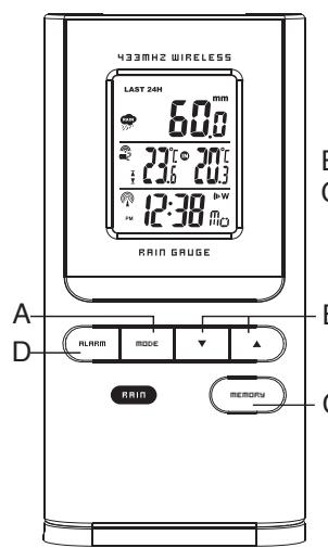
- Display of the total rain amount for the past hour, 24 hours and week
- Rain display in mm or inch can be selected
B Arrow button
- Display of the total rain amount for the past hour, 24 hours and week
- Switch between rain amount display for the past hour, 24 hours and week
C Memory button
- Display of the total rain amount for the past hour, day and week. Press and hold the [MEMORY] button to delete all rain statistics.
D Alarm button
- Hi alarm setting
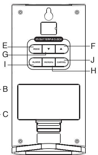
E Mode button (rear panel)
DISPLAY OF TIME AND DATE
Press the [MODE] button to switch between the following displays:
- hour: minutes: seconds
- hour: minutes: weekday
- 2nd time zone
Calendar (month and day depending on format setting).
F'' " arrow button
- Setting of the desired values
- Turn radio clock on/off (keep pressed)
4
G''▼" arrow button
- Setting the desired values
- New search for the sensor signal (keep pressed)
H Memory button
DISPLAY OF MAX./MIN. MEMORY
By pressing the [MEMORY] button, the display switches between current, minimum and maximum temperature (respective to the corresponding channel)
DELETE THE MAX./MIN. MEMORY
Press and hold the [MEMORY] button for about 4 seconds to delete the max./min. memory of all temperatures.
I Alarm button
Setting wake-up time
J Channel button
- Switches the channel (1-3) of the outdoor temperature display
- Press and hold the button in the temperature mode to activate/deactivate the Channel Scan. function
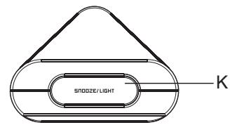
K Snooze / Light button
- Switches on the backlight for about 5 seconds
- Activates the snooze function when wake-up alarm is active
1. INTRODUCTION
We would like to congratulate you on your purchase of the HRG150 rain gauge. The main unit shows the amount of rain, the indoor and outdoor temperature, as well as the time and the date. The outdoor temperature is registered by up to 3 external sensors. The main unit displays the maximum and minimum temperatures measured. Thanks to the 433MHz technology in use, no cable connections are required between the outdoor sensors and the main unit.
Furthermore, the unit is equipped with a radio clock. The clock is synchronized with the current time and the date via the DCF77 time signal. Anytime the device is outside the range of the DCF77 time signal, the time and date can be set manually.
IROX TE150 MANUAL (ENGLISH)
SIZE: W93 X H105 (mm)
BY ROSE KOON 14/09/07
Display unit
(main unit or receiver unit)
2
3
6
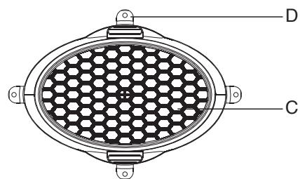
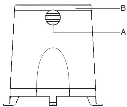
PRECIPITATION AMOUNT SENSOR
A. Funnel seal (adjustment knobs)
B. Molded rain funnel with battery compartment and sensor (2 AA batteries)
C. Protective strainer (view from above)
D. Holes for screws to affix unit
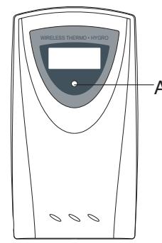
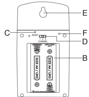
TRANSMISSION UNIT FEATURES
A LED INDICATOR
Blinks once briefly during transmission of temperature data. Blinks twice when the sensor battery is weak
B BATTERY COMPARTMENT
C RESET BUTTON [RESET]
D CHANNEL SWITCH
Set the transmission unit to a channel (1, 2 or 3).
E HOLDER FOR WALL MOUNTING
F°C/F BUTTON
Not available on all devices
8
FOLLOWING Please note the following in order to ensure optima device operation:
- Assign each external transmission unit its own channel.
- First insert the batteries into the transmission units and press [RESET]. Then insert the batteries into the receiver unit.
- Position the receiver unit and transmission within 1 meter of each other and wait until the measurement value appears on the display.
- Then position the receiver unit and the external transmission units within the viable range of the devices - i.e. a maximum of 30 meters from each other.
Please note that the actual range of the transmissions depends upon the construction materials used in the building as well as the respective position of the external transmission unit and external conditions (various radio transmitters and other sources of interference) may also serve to greatly reduce the 30-meter range. In these cases, we recommend locating other positions for both the transmitter and the receiver. Sometimes changing position by just a few centimeters is all that it takes! Although the external transmission units are weather-proof, they should not be positioned where they are exposed to direct sunshine, rain or snow.
9
- PREPARATION OF EXTERNAL
- Remove the cover of the battery compartment.
- Set the desired channel via the sliding switch.
- Insert 2 batteries (1.5V, UM-3 or AA) according to the respective polarities as shown.
- Press the RESET button (e.g. with a paper clip).
- Replace the battery compartment cover and tighten the screws.
- PREPARATION OF RECEIVER UNIT
- Carefully open the cover of the battery compartment.
- Insert the 2 batteries (1.5V, UM-3 or AA) according to the respective polarities as shown.
- Close the battery compartment.
- WALL MOUNT OR ON-TABLE POSITION
The receiver unit comes with a support on the bottom which clicks into place, enabling the unit to be placed on a flat surface.
- "DEAD" BATTERY DISPLAY
Whenever it is time to replace the batteries, an [ ] indicator next to the indoor temperature display (receiver unit batteries) or outdoor temperature (transmitter unit batteries) lights up.
SETTING THE EXTERNAL
SENSOR -TEMPERATURE - AND RADIO CLOCK
a. As soon as the batteries are in the outdoor sensor, the outdoor sensor starts to transmit measurement values at ca. 45 second intervals. The main unit also begins to search for signals as soon as the batteries are inserted (for about 2 minutes). Once the signal is received from the outdoor sensor, the outdoor temperature is shown on the display. The main unit automatically adjusts measurement values every 45 seconds.
b. If no sensor signal is received within 2 minutes, ( ;^) appears on the display. Press the [▼] button for about 3 seconds to trigger a search for the signals of the external sensor.
This is how you synchronize reception and transmission signal between outdoor sensor and the main unit.
c. Once the DCF time signal is received, time and date appear automatically on the display.
10
11
3. PUTTING RAIN SENSOR INTO OPERATION
- Release the funnel on the top surface of the rain sensor by opening the seal with the knobs on the side (turn left).
- Raise the funnel from the lower part of the rain sensor
- Open the battery compartment at the funnel and insert 2 AA 1.5V batteries according to the respective polarities. Close the battery compartment.
- Fasten the lower part of the rain sensor somewhere where precipitation can fall directly into the sensor. Make sure the sensor is fastened in a horizontal position. There is a little spirit level on the inside of the lower part to help you.
- As soon as the lower part of the sensor is fastened correctly, put the funnel back in and lock it using the two knobs.
- Attach the protective strainer onto the top of the funnel.
12
Positioning Tips:
The rain sensor should be attached in an open area away from walls, fences, trees and any other obstacles that might either lessen the precipitation amount or cause precipitation flow from accumulated rainwater (e.g. trees and roofs).
Please also make sure that precipitation can drain off freely around the spot where the sensor is affixed. Check regularly to make sure that no water is collecting in the lower part of the sensor. The rain sensor uses a magnet for measurement so make sure there are no magnetic objects near the sensor which would falsify the measurement.
- Preparation - Putting display unit into operation
- Open the cover of the battery compartment on the back of the display unit.
- Insert 2 AA/1.5V batteries according to the respective polarities.
- Shut the battery compartment.
- Display battery status
The battery status of the external sensor is checked. If "dead battery indicator" appears on the display unit with regard to the indoor/outdoor temperature, replace the batteries immediately.
13
- Leg support / Wall mount
The display unit has a removable leg support. This can be removed and the device can be wall mounted using the opening on the back.
The antenna can be set up on a flat surface or wall mounted using the opening on the back.
4. Putting display unit into operation
- Rain measurement mode
The rain measurement data is transmitted wirelessly to the antenna.
The display device records the entire rain amount for the past hour, the past 24 hours as well as the past 7 days.
The rain amount can be displayed in mm or inches. An audio rain alarm can be set to go off when a certain amount of rain per day is exceeded.
- Rain data reception
As soon as the 2 batteries are inserted into the rain measurement unit, the sensor starts to transmit rain data. As soon as data is received successfully by the display unit, this data is available on the display.
14
- New rain sensor search
The following appears in the rain display if there is no reception
1
If this is the case, begin a transmitter search by pressing the [] button 2 seconds. This kind of transmitter search lasts ca. 2 minutes and is always advisable whenever data transmission is interrupted or the antenna batteries have been replaced.
- Rain amount display
In the rain mode, press the MODE button or the MEMORY button to toggle between the following displays:
- Rain amount of the past hour
- Rain amount of the past 24 hours
- Rain amount of the past 7 days
Tip: The value in the "Rain amount of the past hour" display can be read as mm/std (or inch/std).
- Deleting the saved rain amounts
Press and hold the MEMORY button until the value displayed is zero. This resets all rain values in the display unit to zero.
- Setting the rain unit (mm or inches)
Press and hold the MODE button to toggle between the two units.
15
-
Activating / Deactivating the daily rain alarm
-
Every time the [ALARM] button is pressed in the rain mode, the display switches between current rain data and the rain alarm value ("ALARM HI" appears in the display). When the alarm is deactivated, "OFF" is shown. When the alarm is activated, the programmed value is shown.
-
During alarm display, an alarm can be activated or deactivated with the [] or [] button.
-
Setting the alarm (rain alarm)
-
Press the [ALARM] button to display the rain alarm.
-
Press and hold the [ALARM] button about 2 seconds until "ALARM HI" starts blinking (OFF or a number appears in the display).
-
Press the [▲] or [▼] button to set the value. Confirm your selection by pressing the [ALARM] button.
-
Activating / Deactivating the rain alarm
Every time the [ALARM] button is pressed in the rain mode, the display toggles between current rain data and the rain alarm ("ALARM HI"). When the alarm is deactivated, "OFF" is shown. When the alarm is activated, the programmed value is shown.
During alarm display, an alarm can be activated or deactivated with the [▲] or [▼] button
5. RADIO CLOCK (buttons on back)
INFORMATION ON TIME SIGNAL RECEPTION
The device is designed such that the calendar clock is automatically synchronized as soon as it is within the DCF 77 radio signal.
To ensure good time-signal reception, do not position the device near any metallic objects or electrical appliances to keep interference to a minimum.
The first-time, complete reception of the signal usually takes about 3-5 minutes, depending on the strength of time signal reception. The subsequent cyclical time synchronization only lasts a few seconds.
If reception problems persist, set the clock manually and wait until later at night. The chances of successful reception are greater at night (particularly between midnight and about 4 am). One successful reception per week is sufficient to ensure the clock runs precisely.
| - (blinking) reception activated | - previous reception was satisfactory | - previous reception was not satisfactory or time was set manually | no symbol - radio reception deactivated |
- MANUAL SETTINGS
The device offers various ways to alter basic settings. Select the normal time display. Then press the [MODE] button for 3 seconds to get into the settings mode. Now every time you press the [MODE] button the display shows a function (blinking) which can be set. Then press one of the [] or [] buttons for the respective function.
You can alter the following functions (simply press the [MODE] button in between each respective function in this order):
16
17
-
Use the [] button to switch off the alarm you set or the [] button to switch it on. "OFF" is shown when the alarm is switched off, the wake-up time is shown when the alarm is switched on.
-
After completing your settings (press [ALARM] again), the symbol of the corresponding alarm activated appears.
Warning: Setting the pre-alarm time is done using the same steps. You must, however, select one of the predefined times ranging from 15 to 90 minutes.
- SNOOZE FUNCTION
If the [SNOOZE] button is pressed while an alarm is going off, the alarm will stop sounding. The alarm will go off again after 8 minutes. The wake-up signal goes off for 2 minutes if no other button is pressed. Then the automatic snooze cycle is activated. After the 2 minute wake-up signal goes off 3 times or after 3 snooze cycles (pressed 4 times), the alarm clock automatically does
" W^ or " S^ as is described in the following section.
- TURING OFF AN ALARM
If you press the [ALARM] button (on the back) while the alarm is going off, the alarm stops. The "W" function keeps the alarm activated so that it will go off again at the time selected on the next weekday.
The "I · S" function deactivates the alarm and it will not go off on the next day. To do so, the alarm will have to be reactivated!
20
7. THERMOMETER (buttons on back)
- GETTING OUTDOOR TEMPERATURE
Press the [CHANNEL] button to display the individual channels of the external transmitter units successively. The reception indicator above the channel number display provides information on each channel's signal, as described below. If the measured temperature or air humidity exceeds or falls below the measurement range or there is no reception, the following indicators appear in the display: "..." "HHH" or "LLL".
This device can be set so that the values measured by the external sensors are automatically retrieved and displayed. The value of each channel is shown ca. 6 seconds and then the measurement values of the next channel is shown.
Activate scan mode for external sensors: Press the [CHANNEL] button 2 seconds. The symbol now appears
- Deactivate scan mode for external sensors: Press the [CHANNEL] button 2 seconds.
- READING THE "WAVE" INDICATOR
The "Wave" indicator shows the status of the reception device with regard to the signals. Three various displays may follow:
| The devices functions in the search mode (blinking). | ● |
| Receiver functions on normal reception. | ● |
| No signals received for more than 15 minutes. | ●●°C |
21
-
Display language (English-En, German-DE, French-Fr, Italian-IT or Spanish-SP)
-
Temperature display in ^ C or ^
-
Year
Calendar (Month - Day - display format) (Day/Month or Month/Day)
-
Time format 24hr or 12hr
-
Time (hours - minutes)
The last time the [MODE] button is pressed, the setting function is concluded.
When "ZONE" time is displayed, you can make the time setting according to the relevant time zone (press [MODE] button 3 seconds).
- TIME DISPLAY
In the normal display mode, you can select the following display modes on the display via the [MODE] button:
-
Time with seconds
-
Time with weekday
-
A second time zone with weekday
-
A second time zone with seconds
-
Date
- Permanently switching off radio reception
You can switch radio reception on/off and simply use the device as a regular quartz clock. Press the [▲] button 3 seconds to switch radio reception on/off.
The reception symbol ( ) no longer appears on the display when radio reception is switched off.
6. ALARM CLOCK
- SETTING AND ACTIVATING THE WAKE-UP FUNCTION
The alarm clock has three different alarm functions: "W": Weekday alarm. This alarm will go off every Weekday (Monday - Friday)
" 串 : Single alarm. This alarm goes off just once. This function is ideal for the weekend (SAT, SUN), but can be used any day
"Pre-Al": Pre-Alarm. This is to be woken up earlier should the outdoor temperature drop to 0^ or lower. The following wake-up time delays can be selected:
15, 30, 45, 60 or 90 minutes. The "Pre-Alarm" can be used with both of the above alarm functions but only if at least 1 alarm has been activated. This function is only useful if the channel 1 antenna is really outside.
Setting alarm time:
- Use the [ALARM] button to select the alarm function you wish to set. You may choose from the three alarm functions described above
- Press the [ALARM] button 3 seconds. The hour portion of the wake-up time starts blinking.
- Use the [] or [] buttons to select the hour of the alarm time.
- Press the [ALARM] button again and set the minutes of the alarm time.
- Finally, confirm alarm-time selection by pressing the [ALARM] button again.
18
19
MINIMUM AND MAXIMUM TEMPERATURE
The values for the maximum and minimum temperatures measured are automatically saved. To check over values, press the [MEMORY] button once to see the minimum values. Pressing the [MEMORY] button once again shows the maximum temperature. "MAX" or "MIN" appear correspondingly. To delete the saved values, press the [MEMORY] button 2 seconds: minimum and maximum values are now deleted. Pressing the [MEMORY] button once again shows the current minimum and maximum temperatures until fresh data arrives.
The [MEMORY] button is on the back of the device.
- TEMPERATURE TENDENCY DISPLAY
The tendency indicator shows the temperature tendency of the values measured via the corresponding sensor channel. The indicator can show the three following trends: rising, constant and falling.
| Indicator | TREND | TREND | TREND |
| Trend | rising | constant | falling |
22
8. TECHNICAL DATA
Receiver unit
Indoor temperature : 0^ to +50^
(32^ to +122^)
Temperature resolution: 0.1^
0.2^
External transmitter unit
Measurement range : -15°C to +60°C
Outdoor temperature (5^ to +140^)
Temperature resolution : 0.1^
0.2^ F
Transmission frequency : 433 MHz
Number of channels
Range
Measurement cycle
:3
maximum 30 meters
(in an area free of interference)
: ca. 43 - 47 seconds
Power supply
Receiver unit
: two UM-3 or
AA 1.5V batteries
external transmission unit
two UM-3 or
AA 1.5V batteries
Dimensions
receiver unit
external transmission unit
: 138(L) x 70(H) x 26(D) mm
: 56 x 107 x 24 mm
Rain measurement
Rain measurement precision: + / - (0.8mm) + 5%
Rain measurement resolution: 0.8mm
Rain measurement range : .0mm to 1999.9mm
Rain measurement cycle : 183s
Operating temperature range: -5^ to 50^
Dimensions
Radio rain sensor 163(L) x 177(H) x 119(D) mm
24
CARE INSTRUCTIONS
-
Protect the device from moisture, dust, physical shocks and extreme temperatures and wipe it clean with just a dry cloth without any aggressive solvents.
-
Do not attempt to make any changes to the device yourself as this will eliminate any claim to the guarantee.
-
Use new batteries only and never use old and new batteries together.
Please keep in mind that used batteries should not be disposed of in regular household trash. They should be turned in to the appropriate collection spot. Important : All disposal fees in Switzerland (SENS) and in the EU (WEEE) for all Irox devices have been covered.
PLEASE NOTE
- Due to printing restrictions the way the display is shown in this operating manual may diverge
from the way the actual display appears.
Subject to alterations.
25
EG DECLARATION OF CONFORMITY
Product:HRG150
When used properly, this product complies with the fundamental requirements of article 3 of the R&TTE 1999/5/EC directive:
Efficient usage of radio frequency spectrum
(Article 3.2 of the R&TTE directive)
Applied standard(s)
EN 300 220-1,3:2000
Electromagnetic compatibility
(Article 3.1.b of the R&TTE directive)
Applied standard(s)
EN 301 489-1,3:2000
Applied standard(s)
EN 300 339:2000
Additional information:
The product is thus compliant with the
73/23/EWG low-voltage directive and the
89/336/EWG directive for
electromagnetic compatibility and bears the
corresponding CE label.
Compliant in the following countries :
All EU countries, Switzerland
CH and Norway

QA MANAGER:
K.S plastic factory
Guan Lan / Shen Shen / China


26