
POWERMATE 600 - Powered mixer DYNACORD - Free user manual and instructions
Find the device manual for free POWERMATE 600 DYNACORD in PDF.
| Product Type | Powered Mixer |
| Brand | DYNACORD |
| Model | POWERMATE 600 |
| Number of Input Channels | 8 mono (mic/line) + 2 stereo (line) |
| Microphone Inputs | 8 x balanced XLR with +24 V phantom power |
| Line Inputs | 8 x 6.35 mm balanced jacks (mono channels) + 2 x stereo jacks (stereo channels) |
| Effects Processors | 2 stereo 24-bit processors, 99 programs each |
| Graphic Equalizer | Stereo 7-band with ±10 dB cut/boost |
| Power Amplifier | 2 x 300 W at 4 ohms (estimated), built-in protection |
| Speaker Outputs | 2 x Speakon (pins 1+ and 1-) |
| Other Outputs | AUX send, MONO output, RECORD send (RCA), headphones (stereo jack) |
| Mains Power | Voltage as per label, 50/60 Hz |
| Cleaning | Dry cloth only |
| Ventilation | Do not obstruct front and rear grilles |
| Repairs | Refer to qualified personnel; use original parts for safety components |
| Warranty | 36 months from date of purchase |
| Included Accessories | Power cord, warranty card, user manual |
| Options | FS11 footswitch, rack ears for rack mounting |
| Weight | Not specified |
| Dimensions | Not specified |
Frequently Asked Questions - POWERMATE 600 DYNACORD
User questions about POWERMATE 600 DYNACORD
0 question about this device. Answer the ones you know or ask your own.
Ask a new question about this device
Download the instructions for your Powered mixer in PDF format for free! Find your manual POWERMATE 600 - DYNACORD and take your electronic device back in hand. On this page are published all the documents necessary for the use of your device. POWERMATE 600 by DYNACORD.
USER MANUAL POWERMATE 600 DYNACORD
IMPORTANT SAFETY INSTRUCTIONS 23
IMPORTANT SERVICE INSTRUCTIONS 23
DESCRIPTION 24
UNPACKING AND WARRANTY 24
INSTALLATION 24
INPUT MONO 26
INPUT STEREO 28
FX 1/2 30
AUX/MONO 32
MASTER 34
REAR PANEL 36
SETTINGUPASTANDPARASYSTEM 37
MASTER PATCHBAY 38
SPECIFICATIONS/TECHNISCHE DATEN 61
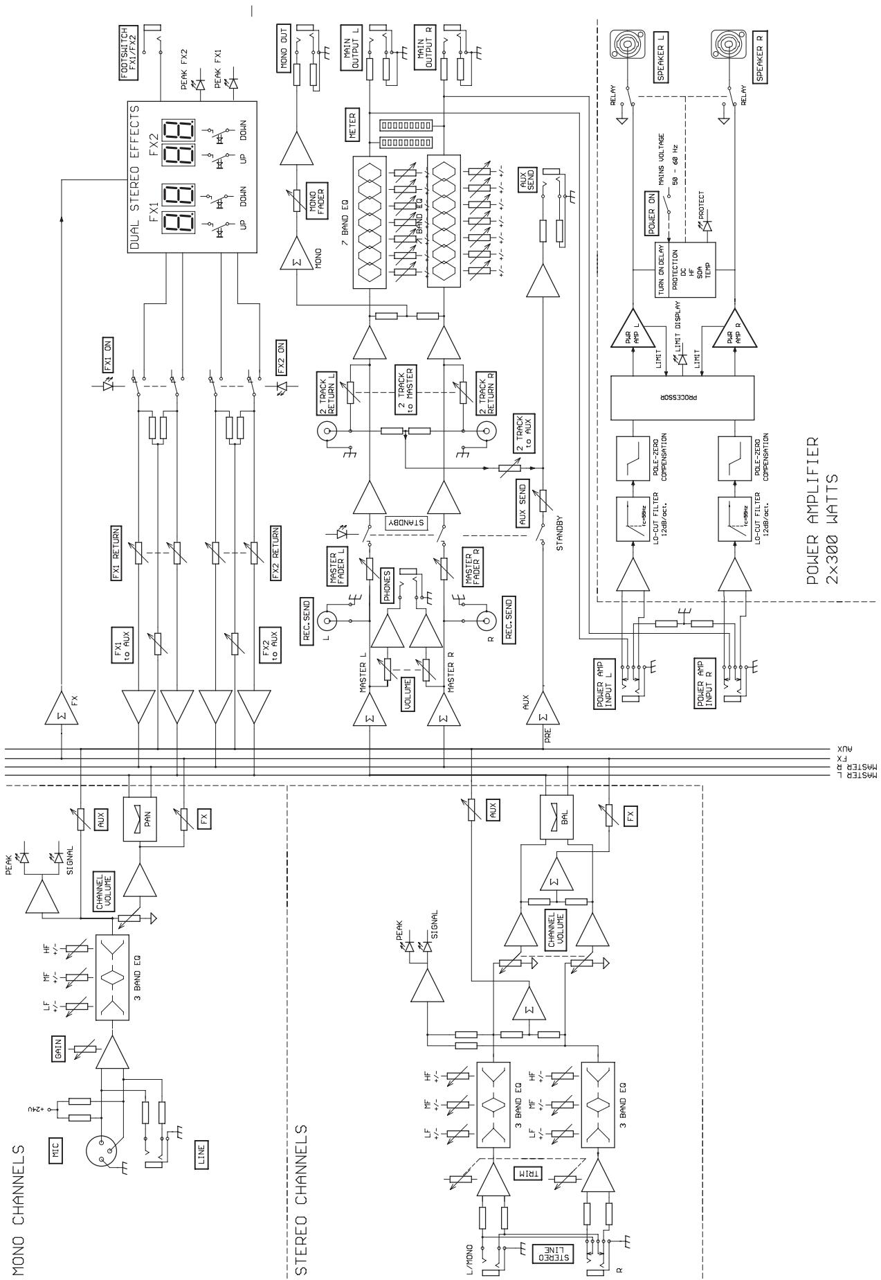
BLOCKDIAGRAM 62
DIMENSIONS/ABMESSAGEUNGEN 63
TABLE DES MATIÈRES
INSTRUCTIONS DE SECURITE IMPORTANTES 43
INSTRUCTIONS DE RÉPARATION IMPORTANTES 43
INTRODUCTION 44
DEBALLAGE ET GARANTIE 44
INSTALLATION ET BRANCHEMENTS 44
INPUT MONO 45
INPUTSTEREO 48
EFFETS 1/2 50
AUX3/4 52
MASTER 54
PANNEAU ARRIÈRE 56
INSTALLATION SONORISATION STANDARD 57
SPECIFICATIONS 61
BLOCKDIAGRAM 62
DIMENSIONS 63
WARNING: TO REDUCE THE RISK OF FIRE OR ELECTRIC SHOCK, DO NOT EXPOSE THIS APPLIANCE TO RAIN OR MOISTURE. AVIS: RISQUÉ DE CHOC ELECTRIQUE. NE PAS OUVRIR.
WARNING: CONNECT ONLY TO MAINS SOCKET WITH PROTECTIVE EARTHING CONNECTION.

IMPORTANT SAFETY INSTRUCTIONS 23
IMPORTANT SERVICE INSTRUCTIONS 23
DESCRIPTION 24
UNPACKING AND WARRANTY 24
INSTALLATION 24
INPUT MONO 26
INPUT STEREO 28
EFFECT 1/2 30
AUX/MONO 32
MASTER 34
REAR PANEL 36
SETTINGUPASTANDARDPA-SYSTEM 37
MASTER PATCHBAY 38
SPECIFICATIONS/TECHNISCHE DATEN 61
BLOCKDIAGRAM 62
DIMENSIONS / ABMESSAGENGEN 63
IMPORTANT SAFETY INSTRUCTIONS

CAUTION
RISK OF ELECTRIC SHOCK
DO NOT OPEN

WARNING: TO REDUCE THE RISK OF FIRE OR ELECTRIC SHOCK,
DO NOT EXPOSE THIS APPLIANCE TO RAIN OR MOISTURE.
AVIS: RISQUÉ DE CHOC ELECTRIQUE. NE PAS OUVRIR.
WARNING: CONNECT ONLY TO MAINS SOCKET WITH
PROTECTIVE EARTHING CONNECTION.

The lightning flash with arrowhead symbol, within an equilateral triangle is intended to alert the user to the presence of uninsulated "dangerous voltage" within the product's enclosure that may be of sufficient magnitude to constitute a risk of electric shock to persons.

The exclamation point within an equilateral triangle is intended to alert the user to the presence of important operating and maintenance (servicing) instructions in the literature accompanying the appliance.
- Read these instructions.
- Keep these instructions.
- Heed all warnings.
- Follow all instructions.
- Do not use this apparatus near water.
- Clean only with a dry cloth.
- Do not block any ventilation openings. Install in accordance with the manufacture's instructions.
- Do not install near heat sources such as radiators, heat registers, stoves, or other apparatus (including amplifiers) that produce heat.
- Do not defeat the safety purpose of the polarized or the grounding-type plug. A polarized plug has two blades with one wider than the other. A grounding type plug has two blades and a third grounding prong. The wide blade or the third prong are provided for your safety. If the provided plug does not fit into your outlet, consult an electrician for replacement of the obsolete outlet.
- Protect the power cord from being walked on or pinched particularly at plugs, convenience receptacles, and the point where they exit from the apparatus.
- Only use attachments/accessories specified by the manufacturer.
- Use only with the cart, tripod, bracket, or table specified by the manufacturer, or sold with the apparatus. When a cart is used, use caution when moving the cart/apparatus combination to avoid injury from tip-over.

- Unplug this apparatus during lightning storms or when unused for a long period of time.
- Refer all servicing to qualified service personnel. Servicing is required when the apparatus has been damaged in any way, such as power-supply cord or plug is damaged, liquid has been spilled or objects have fallen into the apparatus, the apparatus has been exposed to rain or moisture, does not operate normally, or has been dropped.
- Do not expose this equipment to dripping or splashing and ensure that no objects filled with liquids, such as vases, are placed on the equipment.
- To completely disconnect this equipment from the AC Mains, disconnect the power plug from the AC receptacle.
- The mains plug of the power supply cord shall remain readily operable.

Management of WEEE (waste electrical and electronic equipment) (applicable in Member States of the European Union and other European countries with individual national policies on the management of WEEE) The symbol on the product or on its packaging indicates that this product may not be treated as regular household waste, but has to be disposed through returning it at a Telex dealer.
IMPORTANT SERVICE INSTRUCTIONS
CAUTION: These servicing instructions are for use by qualified personnel only. To reduce the risk of electric shock, do not perform any servicing other than that contained in the Operating Instructions unless you are qualified to do so. Refer all servicing to qualified service personnel.
- Security regulations as stated in the EN 60065 (VDE 0860 / IEC 65) and the CSA E65 - 94 have to be obeyed when servicing the appliance.
- Use of a mains separator transformer is mandatory during maintenance while the appliance is opened, needs to be operated and is connected to the mains.
- Switch off the power before retrofitting any extensions, changing the mains voltage or the output voltage.
- The minimum distance between parts carrying mains voltage and any accessible metal piece (metal enclosure), respectively between the mains poles has to be 3mm and needs to be minded at all times. The minimum distance between parts carrying mains voltage and any switches or breakers that are not connected to the mains (secondary parts) has to be 6mm and needs to be minded at all times.
- Replacing special components that are marked in the circuit diagram using the security symbol (Note) is only permissible when using original parts.
- Altering the circuitry without prior consent or advice is not legitimate.
- Any work security regulations that are applicable at the location where the appliance is being serviced have to be strictly obeyed. This applies also to any regulations about the work place itself.
- All instructions concerning the handling of MOS - circuits have to be observed.
NOTE:

SAFETY COMPONENT ( MUST BE REPLACED BY ORIGINAL PART )
First of all, we would like to thank you and congratulate you to your purchase of a DYNACORD power mixer.
The PowerMate compact power mixers incorporate profound know-how, based on our research, development and inter-communication with our customers in the professional audio market, for decades. With a PowerMate you own a power mixer that offers a wide range of functionality in a very compact frame. Forget about the troubling experiences with cabling and matching mixers, amplifiers, FX units, and equalizers. You now own a device with optimally matched components. The mixer's ergonomic console shape and clearly structured controls provide perfect overview for instant access at all times. A gooseneck litlight can be easily plugged into the provided socket to compensate for insufficient lighting conditions. Also during the transport you will quickly learn to appreciate the PowerMate's superiority: recessed handles on the sides, compact dimensions and low weight, plus the sturdy cover that protects the controls from being damaged. However, if you would rather like to install your PowerMate 1000 in a 19" rack shelf, no problem. The only thing you have to do is to replace the plastic side panels by a pair of metal rack mount ears. Through its multiple functions, its high dynamic capacity, and extremely low-noise design in combination with its 24-bit Dual-Stereo effect unit and the high-performance power amplifier, the PowerMate is best equipped for universal use. No matter, whether on-stage, in a home recording environment or in a permanent installation, your PowerMate is the ideal partner to meet your expectations of a professional audio device - effective and reliable. Of course, you want to install and operate your new PowerMate as quickly as possible. Nevertheless, please take the time to do this by means of this user's manual. Starting with input channels, effects and master areas up to the power amp, every section is explained systematically and in detail within this owner's manual. Through the careful perception of the manual you will learn about all functions and find some useful and practical tips for the daily operation of the PowerMate. Even more important, you will find some adjustment guidelines that should be painstakingly carried out; plus the description of a typical sound reinforcement installation, a block diagram, specifications, connection guidelines, etc.... So, take your time and keep on reading.
Unpacking and Warranty
Open the packaging and take out the PowerMate. Remove the FX unit displays' protective foil. In addition to this owner's manual you will find the mains supply cord and the warranty card. Please check, if the warranty registration form is filled out correctly. Only when this form is completed, you will be able to apply for warranty claims. DYNACORD grants 36 months of warranty, starting with the date when you received the appliance from your local dealer. Therefore, we would like to ask you to also keep the original certificate of purchase together with the warranty certificate.
Keeping all papers and the original packaging of the device is generally recommendable, since they come in handy re-selling an appliance.
Installation and Connections
Do not cover the ventilation louvers in the bottom plate of the appliance. Always place the PowerMate on an even surface to allow for sufficient airflow during the operation. The device is equipped with electronically controlled ventilators to protect the power amplifier against thermal overload. The direction of the airflow is front-to-rear. Fresh, cold air enters the mixer at its lower front side and warm air leaves the device through the ventilation louvers in the rear panel. Do not cover the frontal or the rear ventilation louvers. Otherwise the PowerMate automatically enters protect mode to prevent thermal overload. While the protect mode prevents that the device is being damaged, regular operation is impossible during the period of time it is activated. In case the PowerMate is installed in a 19" rack system (vertically), you have to allow at least 2 HU of free space above and 1 HU below the mixer. Of course you can cover the empty space with special blind plates that also have ventilation louvers. Before establishing the mains supply connection, please make sure that the device matches the voltage and frequency of your local mains supply. Check the label next to the mains switch. When switching the power on, the internal fans will run for about 2 seconds at full speed to give you an acoustical signal that the PowerMate is ready to be operated. In addition dust particles that might have gotten into the device get blown out. For a secure connection the SPEAKER OUTPUTS on the rear panel of the PowerMate are provided through professional standard high-performance SPEAKON connectors. The pin assignment of these sockets is 1+ (hot) and 1- (cold).

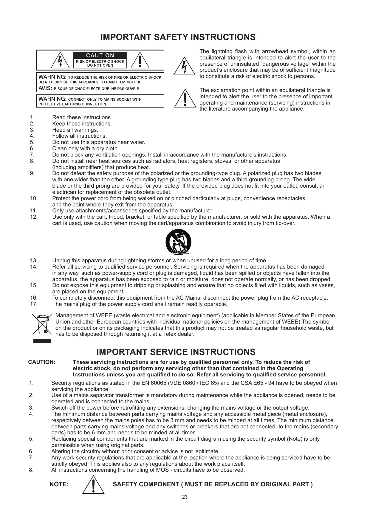
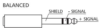
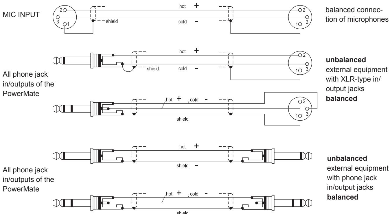
1. MIC
Electronically balanced XLR-type inputs for the connection of low impedance microphones,
likewise the ones that are featured in major studio and live
mixing consoles. This type of input stage provides extraordinary low noise signal conversion at an extremely low distortion rate (typical .002%) even in the high frequency range.
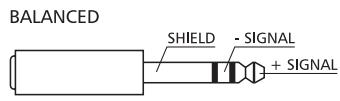
Generally, any type of microphone can be connected as long as its pin assignment is in accordance to the diagram shown aside. Connecting condenser microphones is no problem.
The microphone gets its operational power supply (+24V)
through the mixer and you can forget about battery replacement times.
The connection of condenser type microphones and dynamic microphone models at the same time is possible and does generally not lead to any trouble. Before you do so, please refer to the owner's manual of the microphone. The MIC input is laid out for levels between -60dBu ... +11dBu - depending on the setting of the corresponding gain control. Because of their low impedance design and the phantom power these XLR-type inputs are not meant for cascading other mixing consoles or the connection of FX units, keyboards or other electronic equipment. When connecting this kind of equipment, please utilize the LINE level inputs.
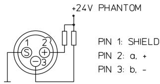
2. LINE
Electronically balanced inputs for the connection of electronic instruments, such as keyboards, drum computers, E-guitars and E-basses with an active output, as well as all other high level signal sources, like additional mixers, FX units, CD player, etc. The LINE input is laid out for levels between -40dBu ... +30dBu. The connection of balanced or unbalanced signal sources is established through monaural or stereo phone plugs, assigned according to the diagram below. If the device that you are going to connect provides a balanced output stage, using balanced cables with stereo phone plugs is certainly preferable. This type of connection is greatly insensitive to the induction of external noise or HF interference.

Do not connect signal sources to a channel's MIC and the LINE inputs at the same time, since the signals cause mutual interference, resulting in a level reduction.
One more note: If possible, please, do not connect E-guitars or E-basses with passive, high impedance outputs directly to one of the mixing console's LINE inputs. The LINE inputs of the PowerMate - like the Line level inputs of mixers from other manufacturers - are meant for the connection of relatively low source impedance as they are found with electronic instruments. The reproduction of the instrument's original sound characteristics will be unsatisfactory - unless this effect is intended. Those instruments should be connected using a special transformer or pre-amplifier with very high input impedance. Musical instruments that are equipped with an active electronic output stage (battery) can be connected without second thoughts.
3. GAIN
Rotary control to adjust the MIC or LINE inputs' sensitivity. These controls let you optimally adjust the incoming signals to the mixer's internal operation level. Cautious adjusting offers the benefits of an improved S/N-ration and provides you with the full bandwidth of the PowerMate's outstanding sound capabilities. On the XLR-type connectors an amplification of +10dB is achieved when the control is set all the way to the left and +60dB when the control is set to its maximum position to the right. Especially when dealing with very low input levels, like they occur during vocal recordings or when the sound source is located in a distance, the high gain is extremely profitable. Using the LINE-input, the signal is generally attenuated by -20dB , while the total adjustment range of 50dB is maintained. The LINE-input's unity gain - no amplification (0 dB) - is achieved at the 20dB mark. The following is meant as a short note for your assistance on how to determine the correct input level:
Note on how to adjust the input level:
- Set the gain control and the corresponding channel fader to their lowest setting.
- Connect the desired sound source (microphone, musical instrument, etc.) to the corresponding MIC or LINE input.
- Play the sound source at its highest volume setting - respectively, sing or speak as loud as possible directly into the microphone.
- While you are playing the sound source or singing into the microphone, adjust the input level using the gain control, so that during the loudest passages the PEAK LED is just not lit, but the SIGNAL-present LED lights constantly. This is the basic channel setting, leaving you with at least 6dB of headroom. Which means, you have at least a range of 6dB before signal clipping.
In case you intend to make further adjustments to the channel's EQ setting, you should perform steps 3. and 4. again afterwards, since changes in the sound shaping section also influence the channel's overall level.
4. EQ SECTION
The mixer's EQ section allows very differentiated shaping of the incoming audio signal within miscellaneous frequency bands. Turning one of the EQ level controls to the right enhances/ amplifies the corresponding frequency range while turning it to the left lowers/ attenuates the signal of the specific frequency band. Before you begin to alter the sound, all EQ controls should be set to their neutral position; that is: their markers point straight up (detent position). Do not set the EQ controls to
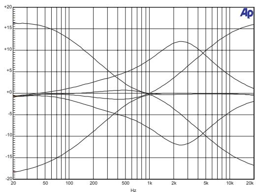
extreme positions. Usually, minor changes are totally sufficient and produce the best results in the overall sound. You should use the natural reproduction as an orientation mark and rely on your musically trained ear, being the perfect instrument to judge the sound quality. The moderate use of the MID control is the best remedy to avoid acoustical feedback. Especially in this frequency range you should try to avoid excessive enhancement. Lowering the level more or less in this band will provide you with high amplification rates without feedback. The EQ section's LO- and HI-controls are designed to work equally effective on both - MIC and LINE -level input sources.
The MID-control is most effective in a relatively wide band around the center frequency of 2.4 kHz. As a matter of fact, especially in microphone applications this specific band turned out to be a critical range. Thus, with almost any microphone it is good advice to slightly reduce the level in this range to gain optimal results.
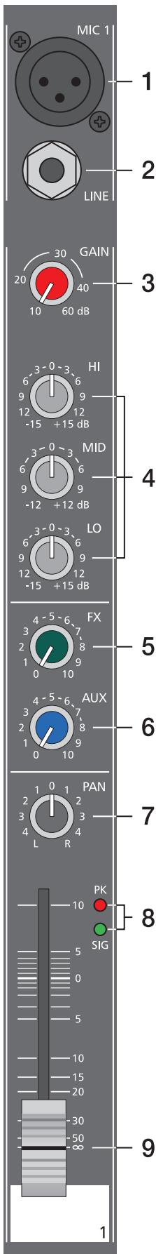
5.FX
The FX-controls are used to adjust individual amounts of the channel signals to be routed to the FX1 and/or the FX2 unit. The split point of the "dry" signal is POST FADE or in other words: the fader setting also influences the signal that is fed to the FX units.Before you start to establish the effect mix, these controls should be set at their center position. From this point you can increase or reduce the effect's intensity, depending on your personal preferences.Please monitor the PEAK LEDs in the FX1/2 channels during a performance. The indicator should only light briefly at the occurrence of high program peaks. If the indicator is constantly lit, please lower the affected channels' send levels at their FX controls. For further information, please refer also to the paragraphs on the FX1/2 units.
6. AUX
The AUX-control is primarily meant for establishing a monitor mix.
The signal is split PRE FADER. The resulting mix - controlled via the AUX-controls and present at the AUX-output in the master section - is not affected by the setting of the channel faders. Especially in microphone applications, operating with moderate AUX-control settings prevents that the monitor signal is acoustically fed back to the microphones.
7. PAN
This control determines the position of the corresponding input signal within the stereo image. When this control is set at its center position, the audio signal is fed with equal levels to the left and the right master busses. Through the extensive PAN section circuitry the essential sound pressure level always stays the same, no matter to what position within the stereo image the PAN control is set.
8. SIGNAL / PEAK indicator
The Signal / Peak indicator has a key function during input level adjustment of the corresponding channel, offering optical information of the actual signal level. It provides the possibility to detect the risk of occurring overdrive before you would actually hear the distortion; unlike the mixers of many other manufacturers that either only provide a PEAK indicator or no channel indicator at all. As described before, the SIGNAL "present" LED should blink in the rhythm of the incoming signal. If this is not the case, you have to increase the gain. If the PEAK LED, on the other hand, blinks frequently or lights up constantly, the corresponding channel is likely to enter clipping and you have to reduce amplification using the gain control. The signal "present" LED lights at levels -30dB below clipping while the peak LED lights at a level of -6dB below the occurrence of overdrive. It is also a good idea to keep an eye on these indicators during a performance, to prevent the mixing console's input channels form clipping caused by increasing volumes.
9. VOLUME
The channel fader is used to set the volume of a single channel and to establish an accurately proportioned mix of all input signals. The channel faders should be positioned within the range of -5dB to 0dB, leaving you with a degree of control that allows precise matching of relative big differences in the channels' level settings. The overall volume is set through the use of the master faders. Even though the channel faders offer an additional gain of +10dB, it is good advise not to exceed the +5dB mark. Despite its special negative gain structure, if the PowerMate's main bus gets "overloaded" with too many "high level" input channels, the summing amplifier could be driven into clipping. It is more reasonable to lower the setting of all faders by about -5dB and increase the overall output level by elevating the master faders. The proportion of the mix and the overall volume stay the same while the risk of clipping is prohibited.
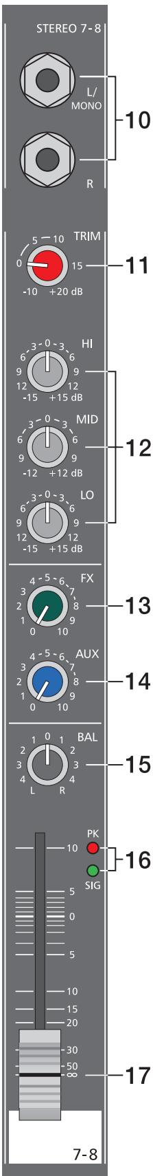
10. STEREO INPUT L/MONO R
Electronically balanced inputs for the connection of musical instruments with stereo output, like keyboards, drum computers, E-guitars and E-basses with an active output as well as any equivalent sound source that provides a high level output; like additional mixing consoles, effect units, compact disc players, etc.
The stereo LINE input is meant for balanced or unbalanced sound sources with levels between -20dBu and +30dBu . For the connection of external devices you can use monaural or stereo phone plugs which are in accordance to the diagram below. If the external appliance is equipped with a balanced output stage, you should preferably use balanced cables and plugs, since this type of connection provides better shielding against RF induction and external noise.

In case you want to connect a monaural signal source to one of the stereo input channels, you just have to plug it into the L/MONO input. The signal is internally linked to both channels.
11. LINE TRIM
These controls serve to match the incoming line level signals of a stereo channel to the PowerMate's internal operation level. The total adjustment range is 30dB. Unity gain – no amplification (0 dB) – is achieved at the 0dB mark. The control allows to attenuate or amplify the signal level in the range of -10dB to +20dB. This range is sufficient for matching most professional, semi professional, and even hi-fi signal sources. Adjustment is performed in accordance with the description of the gain control within the monaural input channel.
If you are using a keyboard as signal source and you have it connected to one of the stereo inputs, please make sure not to set split zones or layers with channel separation. Otherwise the stereo channel mapping will appear like it is set on the keyboard and you will not have the opportunity to re-position the sound in the overall stereo image, using the controls of the mixer. The better alternative to connect a keyboard with pre-programmed channel mapping is to use two adjacent monaural input channels, leaving you the option of placing the sound in the final mix via the PAN controls.
12. TONE CONTROL SECTION
The mixer's tone control section allows very differentiated shaping of the incoming audio signals within miscellaneous frequency bands. Turning one of the EQ level controls to the right enhances/amplifies the corresponding frequency range while turning them to the left lowers/attenuates the signal of the specific frequency band. Before you begin to alter the sound, all tone controls should be set to their neutral position; i. e.: their marker points straight up (detent position). Do not set the EQ controls to extreme positions. Usually, minor changes are totally sufficient and produce the best results in the overall sound. You should use the natural reproduction as an orientation mark and rely on your musically trained ear, being the perfect instrument to judge the sound quality.
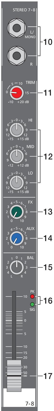
13.FX
These controls determine the amount of the summed L and R signals that are sent to the FX bus. The signal split is POST FADER. For more details on the functioning of these controls, please refer to the INPUT/MONO section of this owner's manual.
14.AUX
These controls determine the amount of the summed L and R signals that are sent to the AUX bus. For more details on the functioning of these controls, please refer to the INPUT/MONO section of this owner's manual.
15. BAL
The function of the stereo channels' BAL controls is equivalent to the PAN controls' function of the monaural channels. If you turn the rotary control all the way to the right, the right signal is outputted to the right output while the signal of the left channel is entirely muted. When the control is set to its center position, the L/R signals are present with their equal intensity on the corresponding outputs. Whenever stereo signal sources are connected to a stereo channel, it is good advice to leave the BAL controls at their center position or make only minor adjustments in either direction. In case a microphone or another monaural audio signal source is connected, the BAL controls function absolutely identical to the PAN controls of the monaural input section.
16. SIGNAL/PEAK
For the stereo SIGNAL/PEAK indicator function, the left and the right channels are monitored independently. The respective highest level reading is indicated, assuring that neither one is already driven into clipping. For further descriptions on how to use this indicator most efficiently, please refer to the previous chapter - INPUT/MONO.
17. VOLUME
The channel fader is used to simultaneously adjust the two volume levels of the stereo signal simultaneously. The functioning is totally identical to the monaural channel fader, as described in chapter INPUT/MONO.
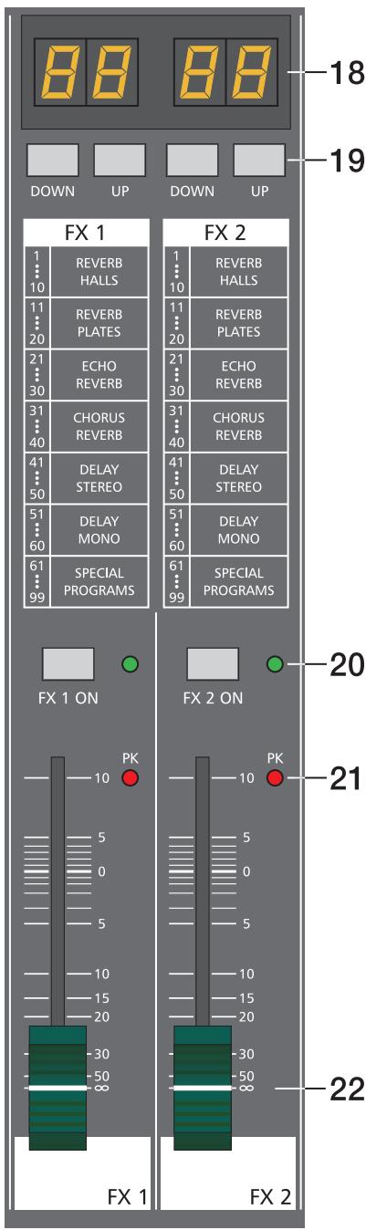
FX1/FX2
The PowerMate offers two independently controllable, identically configured 24-bit stereo effect units - FX1 and FX2. Each unit provides 99 program preset, which are selected by the use of the UP/DOWN buttons. The 99 preset are divided into groups according to their different effect structure, as shown on a printed listing. The programs within each preset group are sorted in ascending order, where higher numbers provide the same FX type with increased intensity. Presets 1 - 20 offer high quality reverberation effect programs that are equally suitable for live performance, recording studio or home recording applications. Program numbers 21 - 40 provide mixed effect types of echo/reverb and chorus/reverb while the numbers 41 - 60 offer different delay effects. The last group from 61 - 99 provides different flanger, chorus, and doubling effects preset as well as special delay and reverb programs. During the initialization of the FX units (when switching on the power of the PowerMate), preset 05 (Large Hall 3 Bright) is selected for the FX1 while the FX2 unit is set to preset 55 (Delay Mono 250ms). These two effects are similarly suitable for live performances and recording applications. This is the factory-preset configuration that can be changed any time. For further information, please refer to the paragraph Changing FX Start Programs.
The two effect programs are equally suitable for live performance or recording applications and can be used separately or together. For testing, evaluating and selecting effect programs, please also refer to the supplementary information form EFFECT PRESETS, which provides detailed description of all effect presets. This listing contains all preset names together with the corresponding effect structure, field of application, and frequency characteristics. Take your time to test all presets and select the ones that are best suited for your specific application. Program number "0" selects a Slap Back Echo, which is mainly for servicing and testing only, and therefore is not included in the effects listing on the front panel. Also provided is a FOOTSWITCH connector, which allows the connection of a footswitch pedal to remotely control the FX units' EFFECT ON/OFF function. If your footswitch features a LED – like the optionally available DYNACORD FS 11 does – this indicator will light when the effect is activated (EFFECT ON).
Changing FX Start Programs
In the factory shipping state, the FX units start with the programs 05/55. If you prefer different programs, you can change and store the new settings in the programming mode. To assign new start programs, please proceed as follows:
- Hold down the two DOWN buttons of FX1 and FX2 simultaneously while switching on the PowerMate.
- "Prog" appears briefly on the display. Programming mode is now active. A software-related side effect is that all buttons behave a bit slower than usual.
- Release the two DOWN buttons and select the desired start programs.
- Press the two UP buttons to store the displayed effect numbers as your new start programs. The FX unit acknowledges the save procedure by briefly indicating "Prog" on the display.
| FX1/FX2 | ||||||
| 1.....10 | 11.....20 | 21.....30 | 31.....40 | 41.....50 | 51.....60 | 61.....99 |
| REVERB | REVERB | ECHO | CHORUS | DELAY | DELAY | SPECIAL |
| HALLS | PLATES | REVERB | REVERB | STEREO | MONO | PROGRAMS |
18. DISPLAY
The display always indicates the actually selected program number of the corresponding FX unit. The display screen is covered with a protective foil to prevent it from being damaged during shipment. Please remove the foil.
19. UP/DOWN
The UP/DOWN buttons are for selecting effect presets. Keeping a button pressed continuously lets you step quickly through the program numbers.
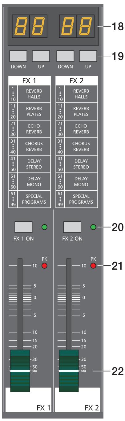
20. FX ON
This switch switches an internal FX unit on and the green LED lights. Please keep in mind that you can also use an external footswitch for the switching of the FX unit. In this case, the LED also shows the actual operational status of the FX unit. If you want to use a footswitch, the FX ON switch has to be engaged first. The corresponding FX unit is activated and you can use the footswitch to switch the selected effect program on or off.
21. PEAK LED
These indicators signal if the internal FX units or the AUX 1/2 SEND signals are on the verge of clipping. To achieve an adequate S/N ratio, please adjust the FX units' input level as follows:
Setting Instructions:
- Establish a "dry" mix - without effect settings - according to the previous descriptions.
- Position the effect return fader of the corresponding effect channel at the -5dB mark.
- Use the UP/DOWN buttons to select the desired FX program preset.
- Press the FX ON switch.
- Play (start the reproduction of) the sound source connected to the desired input channel and adjust the desired amount of the FX signal, using the AUX/FX controls of this input channel. Repeat this step for all input channels that you want to include in your effect mix.
- Monitor the Peak LED so that it only lights frequently at highly dynamic signal peaks. When clipping occurs, reduce the AUX/FX controls in the channels.
- Use the FX to AUX control to add the effect mix to the monitor mix. Use the FX return faders to add the desired amount of the FX signal to the main mix.
In case you are using a different effect setting for the second FX unit, you have to repeat steps 2 - 7, respectively. Pay some attention to the peak indicators when operating your PowerMate to be able to quickly interact when the signal levels exceed the normal range and enter clipping.
22. EFFEKT RETURN
These stereo faders are used to determine the effect amount added to the main mix. In case you have to set these faders at a position above the +5dB mark, please check if the FX unit's input signals are adjusted properly. Otherwise use the AUX/FX SEND controls to increase the input levels.

Generally, the AUX channel is used as monitor bus.
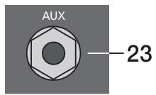
23. AUX SEND
This output serves for the connection of a monitoring power amplifier or active stage monitors. Using the AUX fader, the output level can be adjusted in a wide range up to +20dBu . The AUX send output is designed in Ground Sensing technology to prevent the induction of external noise, even when longer cables are involved.
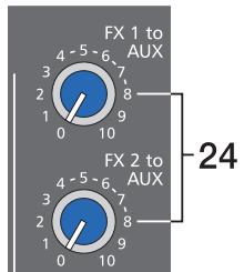
24. FX1/2 to AUX
These controls allow to add the effect signal that is set at the corresponding effect unit to the AUX bus. In case you are using the AUX bus for monitoring purposes, you are able to include the effect signals at the desired levels in the monitor mix. The experience in mixing has shown that the effect level in the monitor mix has to be lower than the level in the main mix, since the distance between the monitor speakers and the artists is much shorter.
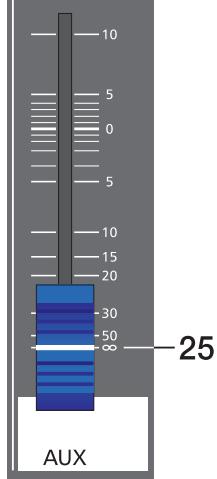
25.AUX VOLUME
This fader controls the AUX SEND output level. So when the AUX bus is used for monitoring, this fader lets you control the monitor system's overall volume setting.
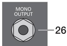
26. MONO OUTPUT
At the monaural output the summed, "post-fade" L/R signal of the master is present. It can be used for additional monitoring, side fill, "next door" and Mono-Pa applications, or to establish a delay-line.
CAUTION:
The outputted signal is affected by the setting of the MONO OUT fader as well as the MASTER faders' setting. In case you would prefer to control the MONO OUTPUT signal independent from the MASTER faders' setting, this can be achieved by some minor internal modification. Please consult your dealer for assistance.
27. STANDBY
Pressing the STANDBY button mutes all outputs to which amplifiers could be connected to the PowerMate. Because this interrupts the signal flow between the mixing stage and the MAIN OUTPUTS, the internal power amplifier's signal is also muted. The STANDBY LED indicates that the stand-by mode is engaged and the input channel signals are not heard over the speaker systems. But, the 2Track Return signal is still fed to the power outputs, providing you with a very comfortable solution to play intermission music during performance breaks.
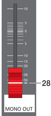
28. MONO OUT VOLUME
This fader controls the output level of the summed L/R master signal at the MONO OUTPUT. The output level is also influenced by the setting of the MASTER faders.

29. PHONES
Stereo phone jack for the connection of headphones with an impedance of 32 - 600 ohms which lets you listen to the PFL master signal.
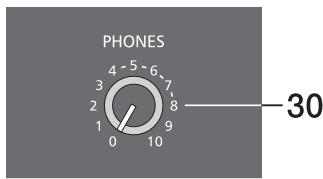
30. PHONES
This control is used to adjust the headphone's volume. CAUTION: Make sure to turn the control all the way to the left (minimum setting) before connecting the headphones.
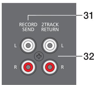
31. RECORD SEND L/R
These RCA-type connectors carry the "pre-fader" master L/R signal. The signal is not affected by the setting of the master faders and therefore mostly used for the connection of cassette decks, open reel tape decks or DAT recorders for recording purposes. The nominal level of the outputs is -10dBV which matches the professional industry standard and home recording applications. Nevertheless, you should use the input gain control of your recording device - as far as it is provided. CAUTION: On most tape decks the incoming signal is directly carried through to the PLAYBACK outputs. In case you have connected the REC. SENDS and the 2TRACK RETURNS and the PowerMate's 2TRACK to MASTER control is set to anything but its lowest setting, the recorded signal is again included into the main mix. The delay difference in delay of the two signals is responsible for occurring drop-outs and a general degradation of the sound. In the worst case, activating the RECORD button on your tape deck could lead to very unpleasant feedback noise. To prevent this from happening make sure to set the 2TRACK to MASTER and the 2TRACK to AUX controls to their lowest settings during a recording.
32. 2TRACK RETURN L/R
These connectors let you connect a tape deck, a CD player, an open reel or an additional SUB-mixer. The signal is post master fader and post STANDBY switch providing you with the possibility to play intermission music during performance breaks or check the mix during the rehearsal, using the headphones. You just have to engage the STANDBY switch to mute all channel signals at the main outputs and the monitor bus.
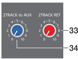
33.2TRACK
ReturnThis control is used to mix the 2TRACK signal to the main mix (MASTER); post-fader of the master controls. CAUTION: When adjusting the level of the device that is connected to the 2TRACK RETURNS – CD player, tape deck, etc. – always start with the control adjusted at its minimal setting. Otherwise, depending on the quality of the recording, the outputted volume can cause relative high levels at the power amplifier outputs.
34.2TRACK to AUX
The signal coming from the 2TRACK RETURNS is internally summed and can be added to the AUX or the monitor bus. The signal's level is set with the 2TRACK to AUX rotary control. Signal summing is done pre-fader to the 2TRACK to MASTER control, i. e. the signal is fed to the AUX output without being influenced by the 2TRACK to MASTER control's setting.
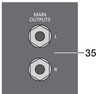
35. MAIN OUTPUTS
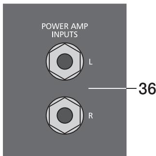
The signals at the MAIN OUTPUTS are post L/R master fader and post the 7-band stereo EQ. They are mainly utilized for the feeding of additional, external power amplifiers. Through these outputs it is also possible to establish a two way active system set-up by either connecting an active frequency crossover or active sub woofers. If you want to use the internal power amplifier to supply the high frequency cabinets, the treble signal coming from the crossover has to be fed back to the PowerMate via the POWER AMP IN connectors.
36. POWER AMP INPUTS
These inputs are provided via electronically balanced phone jacks with breaker function. When inserting a phone plug, the signal path is split up between the master and the internal power amplifier. This provides the opportunity to operate the internal power amplifiers from the POWER AMP INPUTS.
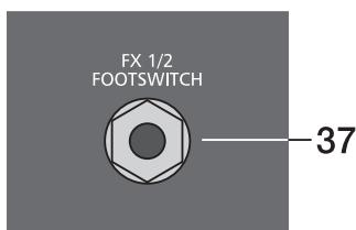
37. FX1/2 FOOTSWITCH
Phone jack for the connection of a DYNACORD FS11 foot switch, to switch the internal FX units on or off. To accomplish this function, the switches FX1 and FX2 have to be engaged.
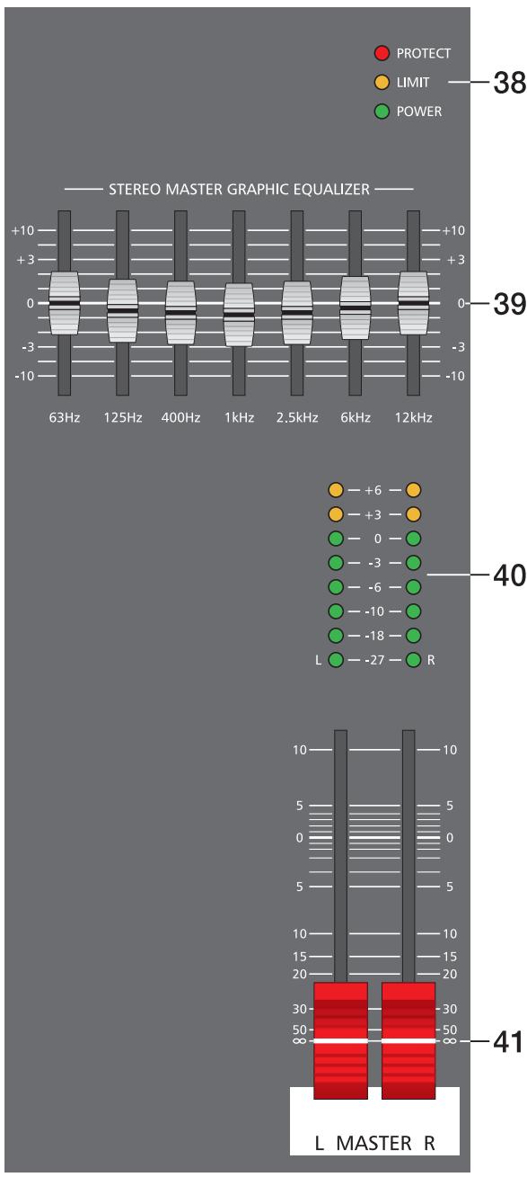
38. STATUS INDICATOR
These indicators are to inform you about the momentary operational status of the PowerMate's internal power amplifier.
The PROTECT indicator lights when one of the power amplifier's extensive protection functions – against thermal overload, HF-induction, DC at the outputs, and SOAR-protection – is activated. When the PowerMate is in protect mode, the speaker outputs are muted and the inputs of the power amplifier are short-circuited to prevent the amplifier from being damaged. In this case you should first check if the frontal and/or rear ventilation louvres are blocked. Another cause could be, that you have connected more than three 8ohms speaker systems per power output. Please also disconnect the SPEAKON connectors and check the speaker cables for short circuits. During the power-on operation, the PROTECT LED always lights for about two seconds. This is normal. It indicates that the PowerMate's protection circuitry is operational.
The LIMIT indicator signals that your operating the PowerMate at the internal amplifier's limit. Frequent blinking of the LED is acceptable, since the amplifier's incorporated limiter prevents the occurrence of distortion. Continuous lighting indicates that a degradation in the outputted sound is likely to happen. In that case, the master level should be reduced.
The POWER ON indicator is always lit when the PowerMate is in operational mode - i. e. it is switched on. If, after switching on the power, the LED is not lit, please make sure that the PowerMate's mains cord is plugged in correctly. If this is the case and the LED is still not lit, please contact your dealer.
The PM600's integrated 7-band stereo graphic equalizer is located in the L/R master channel section. The seven frequency bands - each providing ± 10dB amplification/ attenuation - offer the possibility to optimally match the overall sound to the acoustic conditions of different locations or shape it according to your personal taste.
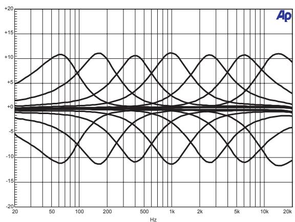
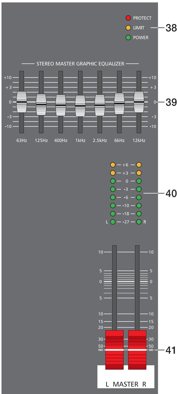
The frequency ranges as well as the characteristics of the EQ-faders are designed very praxis-oriented. In case you intend to have a clear and highly intelligible sound, which, as a side effect, provides the cymbals with more crisp, you should increase the level setting of the 6 kHz or 12 kHz band a bit. If the MIDs are nasaling, try attenuating the mid range by some decibels. If you like to provide your sound with more bass and the kick drum with more punch, you have to boost the low frequency range, using the 63 Hz or the 125 Hz controls. On the opposite, if the overall sound is undefined with too much bass, lowering the levels of these two frequency bands will solve the problem.
Especially when using the equalizer, you should be aware of the fact that in most cases less adjustment provides the better result. Thus, your first choice should be to establish the mix without involving the graphic EQ, using only the tone controls in the input channels and see if you get a satisfactory result.
40. MASTER LED-DISPLAY
The PowerMate offers two 8-segment LED-chains to monitor the output levels of the L/R master signals. The LED-meter's indication range is 33dB, displaying the levels in dBu which are present at the MAIN OUTPUT respectively at the POWER AMP INPUT. In other words: the meter's 0dB mark is referenced to an output signal of 0dBu at the POWER AMP INPUT. Further increasing this level, the power amplifier's maximum input level is reached at the +6dB mark, which equals an output power of 300 watts at 4 ohms per channel. Higher levels are not displayed, since the power amplifier's processor limits the signal at this point which is indicated by the lighting of the LIMIT LED in the status indicator section.
41. MASTER L + R
Level controls to adjust the output signals of the left and right main outputs (MASTER).
NOTE: Please, make sure that the corresponding input channel faders or at least the master faders are set to their minimal position or the STANDBY switch is engaged, before connecting an external signal source to one of the inputs of the PowerMate. This will save you, your audience, and the equipment from unnecessary stress resulting from switching or feedback noise.
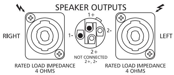
The PowerMate 600 provides professional SPEAKON connectors, offering an electrical and mechanical secure connection which complies to all security regulations allowing the use of high quality speaker cables with a diameter of up to 4 × 2.5mm
The DYNACORD accessory assortment includes all recommended cables and connectors.
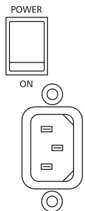
MAINS FUSE
POWER
mains switch to switch the PowerMate on or off.
The PowerMate is operational when the POWER ON - LED lights and the power outputs of the power amplifier are activated.
Please make sure to set the master faders to their minimal position or engage the STANDBY switch before turning the power on. This will save you, your audience, and the equipment from unnecessary stress (switching and/or feedback noise).
In case additional external equipment - like an effect unit - is connected to the PowerMate, please proceed in the following order when switching your equipment on:
- external effect unit
- PowerMate
- external power amplifiers
When switching the power off, please proceed in the opposite order.
CABLING
The mains cord is supplied with your PowerMate. The quality of all other cables is left to your responsibility. Carefully chosen high quality cables are the best precaution to prevent problems from occurring during the later operation. In the following we would like to provide you with some recommendations for the trouble-free operation of your setup.
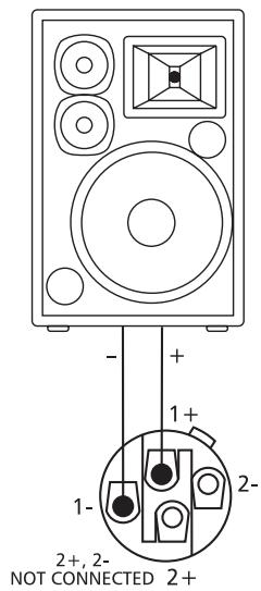
SPEAKER CABLES
Our experience as a manufacturer of loudspeaker systems has taught us that flexible cables with a rubber jacket and a diameter of 2.5mm2 per conductor, used in combination with SPEAKON plugs and sockets, are the best choice to guarantee the optimal connection of loudspeaker systems. The connection of the SPEAKON plugs to the corresponding connectors on the PowerMate's rear panel has to be in accordance to the corresponding diagram below. We recommend the use 4-wire cables where also the pins 2+ and 2- are connected through. This provides you with the possibility to use these cables in an active 2-way system configuration, as well. DYNACORD speaker cables with SPEAKON connectors and all other cables, plugs, and sockets are available at your professional audio dealer.
LF-CABLES-BALANCED OR UNBALANCED?
For LF-cabling – all the low current wiring – your best choice are balanced cables (2 signal conductors + ground shielding) with XLR-type connectors or stereo phone jacks and plugs. The cables should be step proof, shielded, and never longer than absolutely necessary. Too many too long cables mostly lead to confusion and generate unnecessary problems. Of course, you can also connect unbalanced cables with monaural phone plugs to the PowerMate's in- and outputs and because of its superb grounding managing system, in most cases no interference will occur. Still, there is a minimal risk that problems could arise. Generally spoken, if you have the choice, balanced LF-cables are always the better solution and they should be preferred. Today's modern audio equipment – like amplifiers, equalizers, FX units, mixing consoles, and even some keyboards – offers balanced in- and outputs. In a balanced signal path, the cable screen provides a gapless connection of all metal parts, offering efficient shielding against the induction of external noise. The balanced cabling in conjunction with the common-mode rejection of the PowerMate's input stage effectively eliminates even existing artifacts of interference. All inputs of the PowerMate provide balanced audio connections and high common-mode rejection. The mixing stage outputs – AUX, MAIN, etc. – are laid out in GND-SENSING technology – a special, impedance-balanced pin assignment of the output jacks, offering all advantages of the balanced signal transmission, but lets you also connect monaural phone plugs, without a problem. Nevertheless – as mentioned above – when longer cables are involved, using stereo phone plugs and balanced cables are the better alternative. The diagrams below show the pin assignments of plugs and cables like they can be used with the PowerMate.
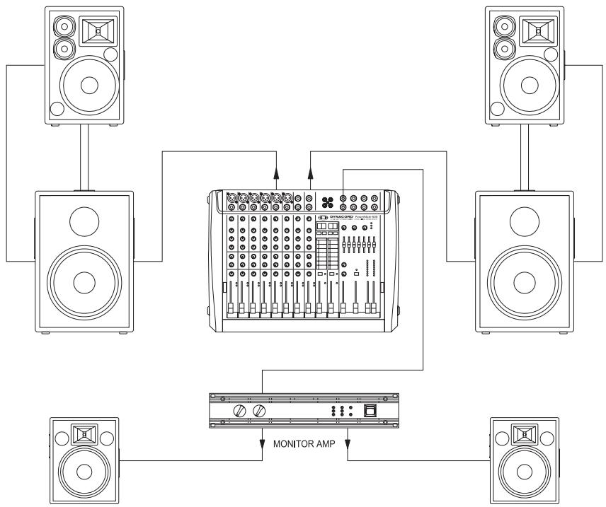
In the following we would like to explain to you how to install a typical sound reinforcement system in passive configuration with incorporated stage monitors. The necessary equipment is:
1 PowerMate 600-2
1 Power amplifier for the monitor signal - for i. e. 2x250 watts
2 Hi cabinets - i. e. 12", 3-way loudspeaker systems
2 Lo cabinets - i. e. 15" woofers
2 Speaker pole-stands or 2 connection rods
2 Stage monitor speakers systems
4 SPEAKON cables (8m) and 2 SPEAKON cables (2m)
1 LF-cable with a stereo phone plug on one and an XLR-type connector on the other end
Setting up
- Place the PowerMate and the external monitor power amplifier in a way that allows their unobstructed operation and connect the mains cord.
- Try to locate the best position for the loudspeaker systems. If possible, the woofers should be placed on the floor while the Hi cabinets' most favorable position is above the Lo cabinets. Please keep in mind, that it is important to have the lower edge of the Hi cabinets approximately at the same height level as the heads of the audience. Either use the connection rods to mount the Hi cabinets on top of the woofers or, if this kind of installation is not possible or if your application does not employ woofers, use separate speaker pole-stands.
- Do not place the left and the right speakers further apart than necessary. The less distance there is between when the two speaker "clusters" – the more compact the sound.
- According to the above diagram, use the SPEAKON cables to connect the woofers and the monitor speakers to the PowerMate and the monitor power amplifier respectively. Make sure not to confuse the channels by accident. Use the short SPEAKON cables to connect the Hi cabinets to the woofer outputs (parallel connection). The two monitor speakers are connected to either one output of the external power amplifier. Set the amplifier inputs to parallel or monaural operation. The amplifier's volume controls provide the possibility to adjust the output levels independently.
- Try to avoid the positioning of the main loudspeaker systems behind the imaginary line of the microphones. Otherwise, if you have to drive the system at higher sound levels, the risk of feedback is very likely.
After you have installed all microphone stands and all artists have found their seat on the stage, the best place to install the monitor speakers is up front facing the musicians. Nevertheless, please make sure that no microphone is directly pointing in the direction of a monitor. You should also be aware of the individual characteristics of the utilized microphones.
-
Using the stereo plug-to-XLR-type connector NF-cable, connect the AUX output of the PowerMate with the external amplifier's input.
-
Connect all microphones – preferably to the monaural inputs of the PowerMate – and the keyboards and other comparable audio signal sources to the rest of the available inputs.
Pull all faders down and engage the PowerMate's STANDBY button. This measure prevents unwanted feedback noise when switching the equipment on. - First, switch the PowerMate on and then the external amplifier. Then activate the PowerMate's operational mode through pressing the STANDBY button again.
SOUND CHECK
-
First, adjust the input levels of the microphones that are connected to the monaural inputs of the PowerMate. Please proceed as follows:
-
Set the corresponding gain controls and the channel faders to their lowest position.
- Speak or sing as loud as possible into the microphone.
- Use the gain control to adjust the level, so that even at loud passages the red PEAK LED is not lit but the green SIGNAL present LED lights constantly.
In case you are also using the stereo input channels, you can adjust their levels as follows:
- Set the LINE TRIM controls and the channel faders to their lowest setting.
- Play the corresponding signal source at the highest volume that is to be expected during the performance.
- Use the LINE TRIM control to adjust the level, so that even at loud passages the red PEAK LED is not lit but the green SIGNAL present LED lights constantly.
or adjusting the EQ of the input channels, please proceed as follows:
- Slide the channel fader and the master faders a bit up, so that you can hear the sound over the main speakers.
- Adjust the EQ controls at their center position.
- Play the corresponding signal source.
- Starting from the center position, you can adjust the controls until the sound is to your liking. Please, keep in mind that major alteration of the EQ-setting does not necessarily result in an improvement of the overall sound. Especially when sound shaping is concerned, less can be more.
- Repeat the steps 2 - 4 for all input channels in use.
If you have musical instruments connected directly to the monaural inputs, follow the descriptions above for the adjustment of the microphones.
Make sure, that all channel faders, gain controls, and LINE TRIM controls of unused input channels are at their minimal setting. In this way you avoid unnecessary noise at the output.
MAIN MIX
-
Establish a basic mix, using the channel faders, so that the individual sound levels relate to each other according to your personal taste.
The best range for the channel faders to be set to is in the area of -5dB to 0dB. In this way you are provided with sufficient tolerance for later adjustments.
Use the master faders to adjust the overall volume of your sound system.
In case you are using the FX units, please proceed as follows: -
Adjust the FX1 return fader at the -5dB mark.
- Use the UP/DOWN buttons to select the desired effect preset.
- Press the FX ON button.
- Play the signal source of the desired input channel and adjust the desired amount of the FX signal, using the FX controls of this specific input channel. Repeat this step for all input channels that you want to include in your effect mix.
- Please make sure that the effect channel Peak LEDs only light frequently at highly dynamic signal peaks.
MONITOR MIX
Lower the setting of the AUX fader within the master section.
Adjust the AUX faders of all input channels that are momentarily in use at their center position.
- Push the AUX fader up as far as absolutely necessary. In this way you have enough headroom before feedback, even when the microphone are not optimally positioned.
Use the FX to AUX control to add the effect mix to the monitor mix, without influencing the main mix. Please keep in mind that normally, the monitor mix needs less effect than the main mix.
Let the artists perform some and check the sound of the system from different angles and distances. If you come to the conclusion that some corrections in the overall sound image are necessary, activate the 7-band stereo equalizer in the master section and match the sound to your liking. By doing so, you should also remember, that during the performance the sound is going to be altered because the audience is present. This circumstance has a major effect on the acoustical condition of the location and its absorption of low frequencies. If possible, check the "sound in the house" during the performance and – if necessary – make adjustments to compensate for the changed conditions.
And for the rest, we like to wish you lots of fun and success with your new PowerMate mixer.
MODE D'EMPLOI
PowerMate 600
Power Mixer
INSTRUCTIONS DE SECURITE IMPORTANTES 43
INSTRUCTIONS DE RÉPARATION IMPORTANTES 43
INTRODUCTION 44
DEBALLAGE ET GARANTIE 44
INSTALLATION ET BRANCHEMENTS 44
INPUT MONO 45
INPUTSTEREO 48
EFFETS 1/2 50
AUX3/4 52
MASTER 54
PANNEAU ARRIÈRE 56
INSTALLATION SONORISATION STANDARD 57
SPECIFICATIONS 61
BLOCKDIAGRAM 62
DIMENSIONS 63
INSTRUCTIONS DE SÉCURITÉ IMPORTANTES

CAUTION
RISK OF ELECTRIC SHOCK DO NOT OPEN

WARNING: TO REDUCE THE RISK OF FIRE OR ELECTRIC SHOCK, DO NOT EXPOSE THIS APPLIANCE TO RAIN OR MOISTURE.
AVIS: RISQUÉ DE CHOC ELECTRIQUE. NE PAS OUVRIR.
WARNING: CONNECT ONLY TO MAINS SOCKET WITH PROTECTIVE EARTHING CONNECTION.

Technical Specifications PowerMate600 Mixing desk in rated condition, Unity Gain (MIC Gain 20 dB), all faders position 0 dB,
all pots in mid position, master fader + 6dB, amplifier rated output power into 8 Ohms, dual channel, unless otherwise specified.
| Maximum Midband Output Power, 1 kHz, THD=1%, Dual Channel | |
| into 4 Ohms | 2 x 270 W |
| into 8 Ohms | 2 x 180 W |
| Rated Output Power, THD=0.1%, Single Channel | |
| into 4 Ohms | 2 x 300 W |
| into 8 Ohms | 2 x 150 W |
| Maximum Midband Output Power, 1 kHz, THD=1%, Single Channel | |
| into 4 Ohms | 2 x 340 W |
| into 8 Ohms | 2 x 200 W |
| Maximum Output Voltage of power amplifier, no load | 43 Vrms |
| THD at 1kHz, MBW=80kHz | |
| MIC input to Main L/R output, +16 dBu, typical | < 0.006% |
| Power amplifier input to Speaker L/R output | < 0.08% |
| DIM 30, power amplifier | < 0.03% |
| IMD-SMPTE, power amplifier, 60Hz, 7 kHz | < 0.2% |
| Frequency Response, -3dB ref. 1kHz | |
| Any input to any Mixer output | 15Hz ... 60kHz |
| Any input to Speaker L/R output | 30Hz ... 40kHz |
| Crosstalk, 1kHz | |
| Fader and AUX-Send attenuation | > 80 dB |
| Channel to channel | > 70 dB |
| CMRR, MIC input, 1kHz | > 80 dB |
| Input Sensitivity, all level controls in max. position | |
| MIC input | -74 dBu (155 μV) |
| LINE Input (Mono) | -54 dBu (1.55 mV) |
| LINE Input (Stereo) | -34 dBu (15.5 mV) |
| Power Amplifier Input | +6 dBu (1.55 V) |
| Maximum Level, mixing desk | |
| MIC inputs | + 11 dBu |
| Mono Line inputs | + 30 dBu |
| Stereo Line inputs | + 20 dBu |
| All other inputs | + 20 dBu |
| Record Send output | + 14 dBu |
| All other outputs | + 20 dBu |
| Input Impedances | |
| MIC | 1.8 kOhms |
| Insert Return | 10 kOhms |
| EQ Input and 2 Track Return | 15 kOhms |
| All other inputs | > 15 kOhms |
| Output Impedances | |
| Record Send | 1 kOhm |
| Phones | 47 Ohms |
| All other outputs | 75 Ohms |
| Equivalent Input Noise, MIC Input, A-weighted, 150 Ohms | |
| Noise, Channel inputs to Main L/R outputs, A-weighted | |
| Master fader down | -90 dBu |
| Master fader 0 dB, Channel fader down | -89 dBu |
| Master fader 0 dB, Channel fader 0 dB, Channel gain unity | -83 dBu |
| Signal/Noise-Ratio, power amplifier, A-weighted | 105 dB |
| Equalization | |
| LO Shelving | ± 15 dB / 60 Hz |
| MID Peaking, mono inputs | ± 15 dB / 2.4 kHz |
| MID Peaking, stereo inputs | ± 15 dB / 2.4 kHz |
| HI Shelving | ± 15 dB / 12 kHz |
| Master EQ, 2x7-band, 63, 125, 400, 1k, 2k5, 6k, 12kHz | ± 10 dB |
| Power Consumption at 1/8 maximum output power, 4 Ohms | 450 W |
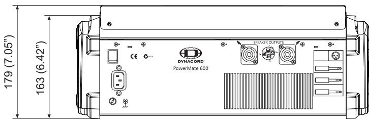
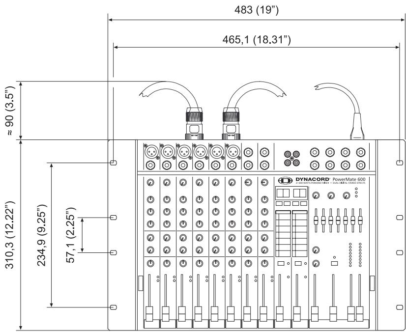
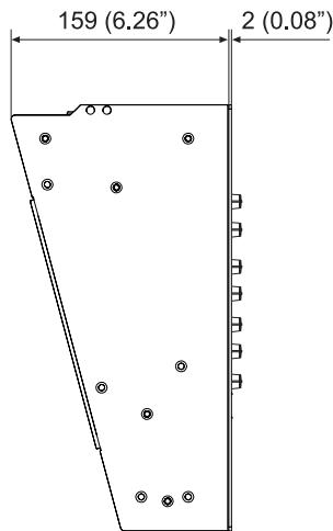
| Dimensions, (WxHxD), mm | 461.5 x 176.5 x 366.5 |
| Weight, without lid | 13kg |
| Optional | |
| RMK-600 (Rack-Mount-Kit PowerMate600) | 112 741 |
| FS11 (Footswitch) | 110 693 |


RACK MOUNTED
Bosch Communications Systems
Americas-Headquarter Americas
Telex Communications, Inc
12000 Portland Ave South,
Burnsville, MN 55337, USA
USA-Ph:1-800-392-3497
Fax: 1-800-955-6831
Canada-Ph: 1-866-505-5551
Fax: 1-866-336-8467
Latin America-Ph: 1-952-887-5532
Fax: 1-952-736-4212
Europe, Africa & Middle-East
Headquarter EAME
EVIAudioGmbH
Hirschberger Ring 45, D-94315,
Straubing, Germany
Phone: +49 9421 706-0,
Fax: +49 9421 706-265
Asia & Pacific Rim-Headquarter Asia
Singapore: Telex Communications (SEA) Pte Ltd
38C Jalan Pemimpin
Singapore 577180
Tel: (65) 6319 0621
Fax: (65) 6319 0620
Japan: EVI Audio Japan Ltd.
5-3-8 Funabashi, Setagaya-Ku,
Tokyo, Japan 156-0055
Phone: +81 3-5316-5020,
Fax: +81 3-5316-5031
Hong Kong: Telex EVI Audio (HK) Ltd.
Unit 5,1/F, Topsail Plaza
11 On Shum Street
Shek Mun, Shatin HK
Phone: +852 2351-3628.
Fax: +852 2351-3329
Bosch Communications Systems
Telex EVI Audio (Shanghai)Co., Ltd.
Room 3105-3109, No.1 Building, No.218, Tian Mu West Road.
Shanghai, China.
Postal Code: 200070
Tel: 86 21-63172155
Fax: 86 21-63173023