
PM2600 - Mixer DYNACORD - Free user manual and instructions
Find the device manual for free PM2600 DYNACORD in PDF.
| Product type | Active universal 2-way power amplifier with subwoofer |
| Brand | DYNACORD |
| Model | PM2600 |
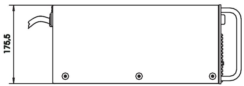
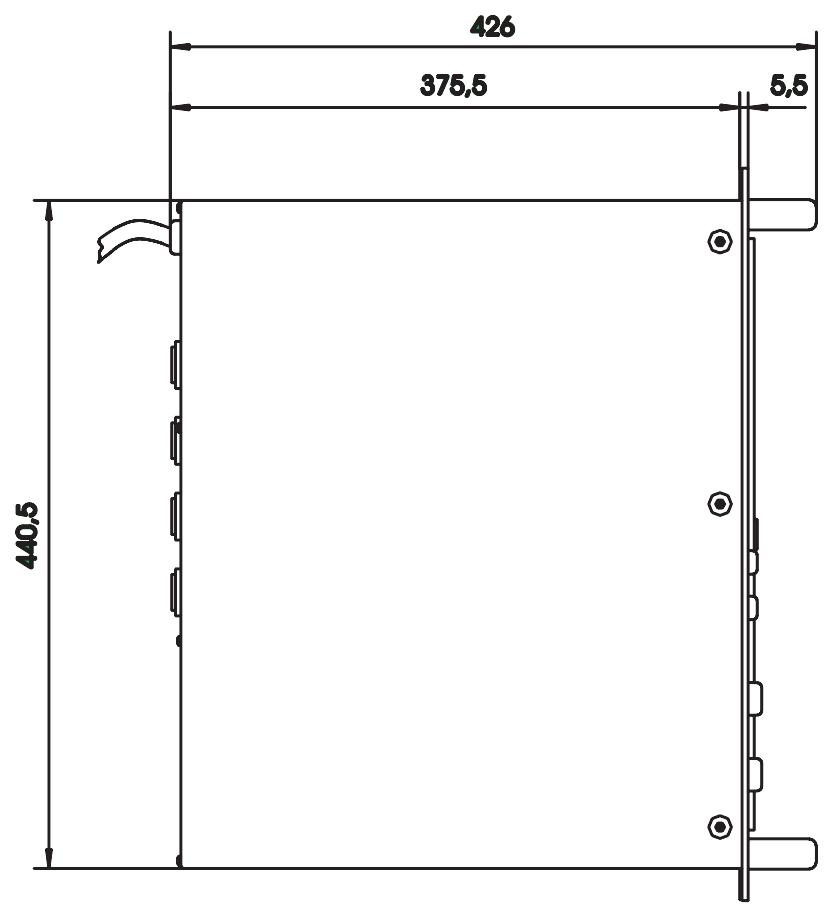
| Dimensions (W x H x D) | 483 x 177 x 426 mm (19", 4U) |
| Weight | 30 kg |
| Output power (LO channel, 4 ohms) | 2 x 700 W (THD = 1 %) |
| Output power (HI channel, 4 ohms) | 2 x 600 W (THD = 1 %) |
| Total power | 2,600 W into 4 ohms |
| Minimum load impedance | 2.5 ohms |
| Input sensitivity | 0 dBu / 775 mV |
| Maximum input level | 21 dBu / 9 V |
| Frequency response (-3 dB, ref. 1 kHz) | 15 Hz - 45 kHz |
| Distortion | < 0.05 % |
| Signal-to-noise ratio (A-weighted, RMS) | > 100 dB |
| Crosstalk | > 60 dB |
| Filter cutoff frequency | 110 Hz (12 dB/octave) |
| Filter type | PowerMax12* |
| Built-in equalizer | Switchable 4 kHz (DIP EQ) with -4 dB, -2 dB and Flat positions |
| Bass level control (LO) | -8 dB to +12 dB relative to treble |
| Audio processors | LPN (Low Pass Notch), dynamic limiters, TBC thermal protection |
| Input connectors | Electronically balanced XLR (pin 1 shield, 2 +, 3 -) |
| Speaker output connectors | 4-pole female Speakon (pins 1+/1- for LO, 2+/2- for HI) |
| Protections | Thermal overload, short circuit, HF, current limiter, power-on relay |
| Operating temperature | 0 °C to 40 °C |
| Cleaning | With a damp cloth only |
| Recycling information | WEEE product, do not dispose of with household waste |
Frequently Asked Questions - PM2600 DYNACORD
User questions about PM2600 DYNACORD
0 question about this device. Answer the ones you know or ask your own.
Ask a new question about this device
Download the instructions for your Mixer in PDF format for free! Find your manual PM2600 - DYNACORD and take your electronic device back in hand. On this page are published all the documents necessary for the use of your device. PM2600 by DYNACORD.
USER MANUAL PM2600 DYNACORD
WARNING: TO REDUCE THE RISK OF FIRE OR ELECTRIC SHOCK, DO NOT EXPOSE THIS APPLIANCE TO RAIN OR MOISTURE.
AVIS: RISQUÉ DE CHOC ELECTRIQUE. NE PAS OUVRIR.
WARNING: CONNECT ONLY TO MAINS SOCKET WITH PROTECTIVE EARTHING CONNECTION.
Thermal Brain Circuit (TBC)
SETTING INSTRUCTIONS 20
SPECIFICATIONS 21
BLOCKDIAGRAM 32
DIMENSIONS 33
IMPORTANT SAFETY INSTRUCTIONS

CAUTION
RISK OF ELECTRIC SHOCK DO NOT OPEN

WARNING: TO REDUCE THE RISK OF FIRE OR ELECTRIC SHOCK, DO NOT EXPOSE THIS APPLIANCE TO RAIN OR MOISTURE.
AVIS: RISQUÉ DE CHOC ELECTRIQUE, NE PAS OUVRIR.
WARNING: CONNECT ONLY TO MAINS SOCKET WITH PROTECTIVE EARTHING CONNECTION.
The lightning flash with arrowhead symbol, within an equilateral triangle is intended to alert the user to the presence of uninsulated "dangerous voltage" within the product's enclosure that may be of sufficient magnitude to constitute a risk of electric shock to persons.

The exclamation point within an equilateral triangle is intended to alert the user to the presence of important operating and maintenance (servicing) instructions in the literature accompanying the appliance.
- Read these instructions.
- Keep these instructions.
- Heed all warnings.
- Follow all instructions.
- Do not use this apparatus near water. Do not expose this apparatus to dripping or splashing and ensure that no objects filled with liquids, such as vases, are placed on this apparatus.
- Clean only with a dry cloth.
- Do not block any of the ventilation openings. Install in accordance with the manufactures instructions.
- Do not install near any heat sources such as radiators, heat registers, stoves, or other apparatus (including amplifiers) that produce heat.
- Only use attachments/accessories specified by the manufacturer.
Refer all servicing to qualified service personnel. Servicing is required when the apparatus has been damaged in any way, such as power-supply cord or plug is damaged, liquid has been spilled or objects have fallen into the apparatus, the apparatus has been exposed to rain or moisture, does not operate normally, or has been dropped - To completely disconnect mains power from this apparatus, the power supply cord must be unplugged.
IMPORTANT SERVICE INSTRUCTIONS
CAUTION:
These servicing instructions are for use by qualified personnel only. To reduce the risk of electric shock, do not perform any servicing other than that contained in the Operating Instructions unless you are qualified to do so. Refer all servicing to qualified service personnel.
- Security regulations as stated in the EN 60065 (VDE 0860 / IEC 65) and the CSA E65 - 94 have to be obeyed when servicing the appliance.
- Use of a mains separator transformer is mandatory during maintenance while the appliance is opened, needs to be operated and is connected to the mains.
- Switch off the power before retrofitting any extensions, changing the mains voltage or the output voltage.
- The minimum distance between parts carrying mains voltage and any accessible metal piece (metal enclosure), respectively between the mains poles has to be 3mm and needs to be minded at all times. The minimum distance between parts carrying mains voltage and any switches or breakers that are not connected to the mains (secondary parts) has to be 6mm and needs to be minded at all times.
- Replacing special components that are marked in the circuit diagram using the security symbol (Note) is only permissible when using original parts.
- Altering the circuitry without prior consent or advice is not legitimate.
- Any work security regulations that are applicable at the location where the appliance is being serviced have to be strictly obeyed. This applies also to any regulations about the work place itself.
- All instructions concerning the handling of MOS - circuits have to be observed.
NOTE:

SAFETY COMPONENT ( MUST BE REPLACED BY ORIGINAL PART )
Universal Controlled Power Amplifier For Professional Active 2-Way Systems With Sub Woofers
Dual Active 2-Way PowerMax Controlled Amplifier
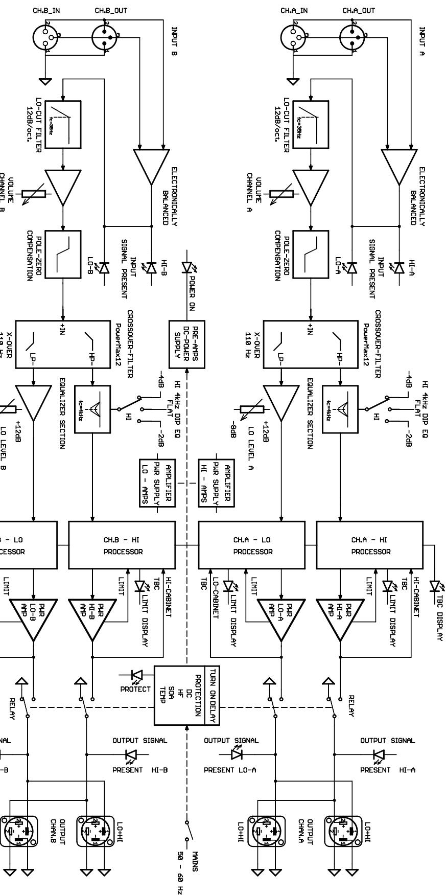
The PM2600 4-channel controlled power amplifier provides an overall output power capacity of 2600 watts into 4 ohms. Although being suitable for universal use, the amplifier has been mainly designed to easily accomplish professional active 2-way sound reinforcement installations incorporating full-range loudspeaker systems and sub woofers. This controlled power amplifier provides an integrated PowerMax12 frequency crossover, several processor-controlled functions, equalizers for matching the sound to acoustic necessities of the location or to the incorporated loudspeaker cabinets respectively, as well as extensive protection circuitry. The four power amplifier blocks of the PM2600 are designed in "Linear Precision Topology". This meanwhile legendary concept provides highest audio quality with an output power capacity of 2 × 700W / 4 ohms for the LO-channels and 2 × 600W / 4 ohms for the HI-channels. Up to three loudspeaker systems with a nominal impedance 8 ohms each can be connected to each output channel. The newly developed PowerMax12* frequency crossovers optimally utilize the amplifiers powerful performance as well as the reproduction and transmission abilities of full-range loudspeaker systems and sub woofers. Compared to conventional frequency crossovers, this ensures outstanding sound improvement with less effort. With a crossover frequency of 110Hz , 12dB/octave, basically any full-range / sub woofer combination can be operated.
Equalizer Section
The PowerMax12 frequency crossover's recommended crossover frequency is 110Hz . It employs an integrated, switchable 4kHz dip-equalizer which allows to match the mid-range frequency response to the characteristics of several different full-range cabinets and to the requirements of individual acoustical environments. The equalizer also provides the opportunity to accomplish a more discrete sound image in near field applications. The "FLAT" position guarantees the most improved directive and intelligible reproduction abilities of the sound reinforcement system providing optimal long-throw coverage. The level of the LO-channels can be set between -8dB and +12dB in relation to the HI-outputs which also contributes to the perfect matching of loudspeaker system models and environmental requirements. The integrated Lo-Cut filter eliminates unwanted sub-sonic noise.
LPN Processors
The integrated LPN (Low Pass Notch) audio processors are responsible for linearizing the frequency and phase response of the connected cabinets. These processors optimally match the typical transmission abilities of small and medium size full-range loudspeaker cabinets and sub woofers. Together with the PowerMax12 frequency crossovers they produce a tight and contoured sound image; especially with drums and bass.
Dynamic Limiters
Four extremely fast audio processors continuously monitor the internal and external operational state of the amplifier blocks, activating the dynamic limiters on the occurrence of any audible non-linearity. This concept ensures absolutely distortion-free sound reproduction even at the highest playback levels and reliable protection for all connected loudspeaker components.
Thermal Brain Circuits
In dynamic peaks, the Linear Precision power amplifier blocks are capable of producing much higher output than the stated 700 watts. In return this guarantees the outstanding overall dynamic range of the sound system. Four Thermal-Brain circuits simulate the thermal model of typical loudspeaker components, limiting the energy that is fed to the speaker systems during continuous overload.
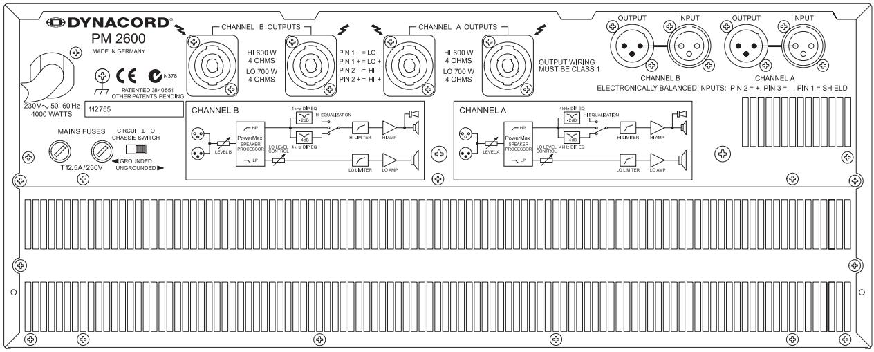
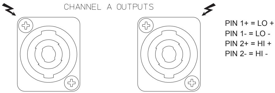
Speakon Female-Type System Output Connectors
The SPEAKON-type loudspeaker output connectors directly provide the LO audio signals (pin1+, pin1-) for the sub woofers as well as the HI audio signals (pin2+, pin2-) for the connection of full-range cabinets. Using 4-pole DYNACORD system speaker cables (PSS 404, PSS 415), active 2-way configurations with sub woofers are easily realized - quick and reliable - since inadvertent mismatching LO and HI channels is virtually impossible. The DYNACORD full-range cabinets of the FORUM Line Series employ a pin-assignment selector switch on their rear panel. This feature offers the possibility to incorporate FORUM Line loudspeaker systems either in active 2-way systems with sub woofers or in full-range applications without a problem.
Balanced XLR Inputs
Each electronically balanced XLR-type input is connected parallel to an additional XLR-type socket, allowing to distribute the input signal to external power amplifiers. It is also possible to directly connect the inputs of channel "A" and channel "B" via these sockets. A feature that is very practical when the set-up contains two PM2600 - one for each side of the stage - and identical audio signals are reproduced via channel "A" and channel "B".
*Patents pending

FOR RECYCLING INFORMATION CONTACT YOUR DISTRIBUTOR OR VISIT OUR WEBSITE
WWW.EVIAUDIO.COM
WEEE Recycling/Disposal Instructions
The Wheelie Bin symbol found on the product or in the manual indicates that this product must not be disposed of with other waste. It is in our category the manufacturer's responsibility to properly dispose of their waste electrical and electronic equipment (WEEE) at the end of its life. Due to the differences in each EU country's management of WEEE, please contact your local distributor. We are committed to facilitate our own electronic-wastemanagement-system, for the free of charge return of all EVI Audio GmbH products: Telex, Dynacord, Electro-Voice, Midas Consoles, KlarkTeknik and RTS. Arrangements are made with the dealer where you purchased the equipment from, for the returning of all unusable equipment at no cost, to the factory in Straubing, for environmental protective disposal.
CHANNEL A, B
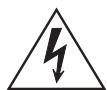
Level Controls For The Channels A, B
These level controls are used to adjust the power amplifier's input sensitivity. They should be positioned between their "0" and -6 dB mark. Too low settings for the input sensitivity can result in distortion in the output stages of the connected mixing console which then off course would also effect the processor stage of the power amplifier.
Input Signal Indicators For The LO/HI Channels A, B
The input signal indicators are located pre-input level controls, indicating the audio signals outputted from the connected mixing console. The LEDs also light when the power amplifier's level controls are set to their minimum position. This ensures that, when setting up the sound system, the audio signal can be optically monitored at the power amplifier, without the need to reproduce the sound through the loudspeaker systems.
Output Signal Indicators For The LO/HI Channels A, B
These LEDs indicate the output voltage of the power amplifiers. The LO-indicators represent the output voltage of the bass power amplifiers while the HI-indicators represent the output voltage of the MID-HI power amplifiers. The LEDs are directly fed from the output connectors which additionally provides optical information of short-circuits in loudspeaker lines. Whenever a faulty condition like a short-circuit occurs and even though the audio signal is reproduced, the corresponding indicator does not light at all or is dimmed.
LIMIT
The limit indicators light whenever the internal limiter is activated and the power amplifier is operated at its limits. Short-term or frequent blinking does not represent any problem. If the LEDs are continuously lit, reducing the output level is recommended to prevent the connected loudspeaker systems from being damaged by overload or clipping.
Thermal Brain Circuit (TBC)
The internal power amplifiers are capable of producing output peaks that by far exceed the nominal output power capacity as stated in the specifications. To protect the connected loudspeaker systems from being damaged, the TBC reduces the output power: either after a short period of time when the regular output level is continuously exceeded, it is reduced to its nominal value or, depending on the overdrive condition, even a bit lower. A lit LED indicates that the sound system is operated exceeding its output capacity which means, that the connected loudspeaker systems operate in a thermally critical range. In this case reducing the output level of the mixing console is strongly recommended.
PROTECT
This indicator lights during operation when one of the protection circuits - thermal overload, short-circuit or HF at the outputs - has been activated. Whatever caused the defect - for instance a short-circuit in one of the loudspeaker lines - has to be eliminated. In case of thermal overload, you have to wait some time until the power amplifier automatically re-enters operation mode.
POWER CN
IndicatorWhen the power amplifier is in operation mode the LED lights. If the LED does not light after switching the power on, presumably the mains cord is not correctly plugged in or one of the mains fuses is blown.
POWER Switch
This push-button switch turns the power on. The loudspeaker outputs are switched delayed via relay. This prevents any power-on noise from being heard. An initial inrush current limiter circuit protects the entire system from being damaged during the power-on operation.
EQUALIZER SECTION
The controls and rotary selector switches of the equalizer section marked "LO" and "HI" are used to match the system to different loudspeaker system configurations as well as for the compensation for acoustic problems of the location.
a) HI Rotary Selector Switch
This rotary selector switch can be set to three different positions. It is used to acoustically improve the MID-HI frequency range.
FLAT
Set to this position, the MID range is reproduced with a higher level. This setting is preferable for lower and medium volumes and for achieving best intelligibility.
- 4dB
Set to this position, the MID range at 4kHz is attenuated by 4dB. Sound reproduction - especially at higher volumes - sounds less aggressive.
- 2dB
Set to this position, normally represents a good compromise. It is not too "sharp" and at the same time not too "polite". Compared to the -4dB-setting, the upper MID range is a little less attenuated.
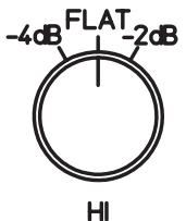
4 kHz DIP EQ
b) LO Rotary Selector Switch
Using this rotary selector switch lets you match the sound reinforcement system to different acoustic requirements of the environment. It also lets you the volume levels of the bass channels.
The rotary selector switch is also utilized to adjust the balance of the LO and MID-HI frequency range, matching the operator's sound expectations. Therefore, the following notes are only meant as inspiration.
0dB
This is the factory pre-set state when shipped. The voltage gain, in relation to the level of 0dB at 1kHz, is equal for the LO and MID-HI channels.
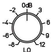
LEVEL CONTROL
0dB.....-8dB
These positions are preferably used when each MID-HI cabinet is accompanied by several sub woofers. The LO-frequency range level is attenuated in relation to the MID-HI range.
0dB....+12dB
These positions are preferably used when each MID-HI cabinet is accompanied only by a single subwoofer system. In relation to the level of the MID-HI range, the LO-frequency range level is raised.
Mains Fuses Of The LO-Power Amplifiers (Channel A/B)
The left fuse protects the power supply of the LO-power amplifiers in both amplifier channels A and B.
Mains Fuses Of The HI-Power Amplifiers (Channel A/B)
The right fuse protects the power supply of the MID-HI power amplifiers in both amplifier channels A and B.
Ground-Lift Switch
This switch separates the enclosure electrically from the ground potential which helps in preventing "noise-loops". Noise-loops result from several devices being connected to the ground via mains plugs, when installed in a rack-system via direct metal contact, and through the screen of connected LF-signal lines.
Grounding Screw
The grounding screw is located next to the ground-lift switch. When the PM2600 is included within a rack-shelf system, this screw is meant for the connection of an "earth bar". Whenever several devices are installed in a rack-system, they should be connected to a common ground, since their lacquered front panels prevent a perfect galvanic inter-connection between enclosures.
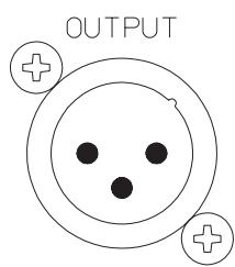
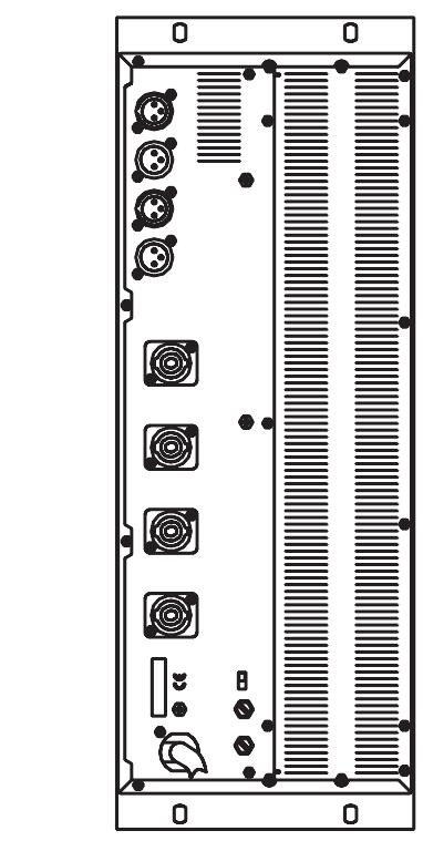
Power Amplifier Output Connectors
The power amplifier channels A (left) and B (right) are provided with 2 individual, output connectors that are connected parallel. The outputs of the LO amplifier channels are present at PIN 1+ and PIN 1- while the MID-HI amplifier channels are present at PIN 2+ and PIN 2-.
Pin-assignment of the output connectors
Power Amplifier Input Connectors
Each XLR-type input connector provides a parallel connected socket which offers the possibility to connect the input signal through to additional external power amplifiers.
The power amplifier inputs are electronically balanced. Their pin-assignment is according to the IEC 268 standard.
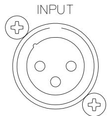
CHANNEL A
Pin-assignment of the XLR-type input connectors
PIN 1: SHIELD
PIN 2: a, +
PIN 3: b, -
The inputs are electronically balanced.
Despite the fact that many mixing consoles provide XLR-type output connectors, often enough their actual signal path and pin-assignment is carried out unbalanced. In case a mixing console with unbalanced outputs is connected to the PM2600, you are presented with two alternatives: either bridging PIN1 and PIN3 of the power amplifier input connectors or disconnecting the PIN3 at the plug of the connection cord.
When transmitting audio signals from unbalanced to balanced devices via PIN3 (b, -, "cold") and PIN2 (a, +, "hot"), this possibly results in humming and HF-interference noise, which very likely might damage your power amplifier and/or the connected loudspeaker systems.
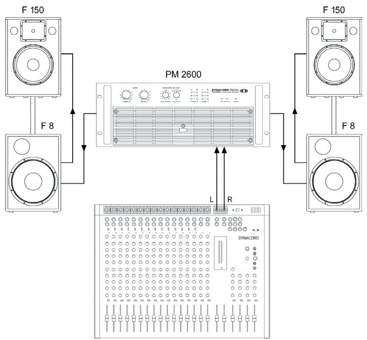
Installation Instructions
When installing a sound reinforcement system for halls or festival tents over their entire length, the loudspeaker systems have to be set up on the left and right sides of the stage, slightly pointing to the center, resulting in a beam-shape coverage pattern over the entire length of the hall or festival tent. Placing the MID-HI cabinets on both sides on top of each other ("STACKING") provides improved long-throw coverage. Stacking the loudspeaker systems in this way almost doubles the coverage while at the same time the near filed reproduction is not too loud.
When installing a sound reinforcement system for halls or festival tents on the wider wall side, the loudspeaker systems have to be set up on the left and right sides of the stage, aimed towards the audience. Because of the wider horizontal dispersion angle needed ("covering the front and the sides"), this kind of sound reinforcement application can only be satisfactory realized when employing 2 MID-HI cabinets per side. In these cases, exceptionally preferable is the "stack and splay" technique - turning the two MID-HI cabinets which are placed on top of each other. This results in smoother sound reproduction over the entire audience area.
In many halls and festival tents the bass response can be dramatically improved by placing the woofer systems directly on the floor instead of setting them on the stage. In return this requires that the MID-HI cabinets are installed on loudspeaker pole-stands.
- Arraying woofer systems to a central "cluster" results in extreme bass SPL in the near field of the "woofer cluster". The SPL drops rapidly over the distance.
Compared to the woofer-cluster-configuration, placing the woofer systems de-centralized on the floor along the edge of the stage results in a reduced low-frequency SPL in the audience area next to the stage. But on the other hand, the bass response and punch stays constant over a wider distance.
SETTING INSTRUCTIONS
- Set all tone controls on the mixing console to their center (neutral) position (linear setting).
- Bypass any existing 3rd-octave or octave equalizers or set the EQ-controls to their center (neutral) position.
- Connect a microphone and by using the LO-control of the power amplifier's equalizer section adjust the bass response, so that the human voice sounds "natural". Using the 4kHz DIP-EQ lets you adjust the response of the upper mids band (4kHz) according to your personal preferences.
In the "FLAT" position, the volume of the upper mid frequency range is loudest, providing the voice with best intelligibility. At higher reproduction levels the audio system sounds more aggressive.
In the “- 4dB” position, the upper mid frequency range is attenuated by 4dB at 4kHz. The human voice sounds less direct.
In the “- 2dB” position, the upper mid frequency range is attenuated by 2dB at 4kHz. This setting is most suitable when the system is frequently used in different locations and at high SPL.
- This completes the system's basic settings.
- Using the tone controls in the microphone and musical instrument channels of the connected mixing console, you can adjust and balance the overall sound according to your personal preferences.
EQUALIZER
If incorporating 3rd-octave or octave equalizers at all, they should only be used extremely careful. With most 3rd-octave or octave equalizers, even minor attenuation or raise of LO or MID range levels leads to intolerable sound degradation, which in most cases cannot be excluded anymore by using other, "regular" tone controls.
SOUND SETTING USING REAL TIME ANALYZERS AND EQUALIZERS
Generally, the "Sound Setting" of sound reinforcement installations using real-time analyzers and dynamic 3rd-octave or octave equalizers is not advisable. Especially 3rd-octave equalizers often generate - depending on their setting - phase and group delay distortions that degrade the sound quality tremendously. The measuring microphone evaluates the direct sound coming from the loudspeakers and at the same time all the reflections which bounce back from any obstacles in the environment. This circumstance makes a useful interpretation of the measured data under acoustic aspects basically impossible.
If, because of extreme acoustic conditions analyzing/equalizing is unavoidable, it is advisable to mind the following precautions:
- Measure only the loudspeakers' near field. Normally, this means a distance of approximately 3m to 5m . When positioning the measuring microphone in a further away (e.g. in the center of a hall) not only the direct sound is measured but also the amount of room reverberation. Trying to linearize "mush" via EQ, generally leads to an extremely mid-boosted, metal, aggressive sound.
- When measuring the range between 250Hz and 5kHz (the "critical range"), the EQ should only be used to attenuate the signal and never to increase it! A "hole" in the sound spectrum is not experienced as unpleasant, as an "arch". Excessively increasing the low-frequency range is also not advisable, since this drastically degrades the transient response of the entire sound system.
- To prevent power amplifier clipping and the distortion that goes along with it, during the measuring procedure the maximum output power should not exceed 5W (Pink Noise). The noise-voltage peak value of regular noise generators is approximately 10dB higher than the effective value. With an average output power of 5W short-term peaks can reach up to 50W.
It is possible to use 3rd-octave or parametric EQs to reduce the negative effect of dominating acoustic feedback. Being extraordinarily sensible and careful is also recommended for this kind of application, since often enough gaining a higher output level goes along with loosing lots of intelligibility and fidelity.
DUAL 2600W ACTIVE 2-WAY PROCESSED PRECISION POWER AMPLIFIER
| PM 2600 | |
| Input Sensitivity | 0 dBu / 775 mV |
| Maximum Input Level | 21 dBu / 9 V |
| Frequency Response (-3dB, ref. 1kHz) | 15 Hz - 45 kHz |
| Distortion | < 0.05 % |
| Crosstalk | > 60 dB |
| S/N ratio (A, RMS) | > 100 dB |
| Slew-Rate (intern) | > 30V/ μsec |
| Attenuation (1kHz, intern) | > 300 |
Output Power
| LO channel at 4 ohms | 2 x 700W / THD = 1% |
| MID/HI channel at 4ohms | 2 x 600W / THD = 1% |
| Minimum Load | 2,5 ohms |
| X-Over Frequency | 110 Hz |
| X-Over Filter Type | PowerMax 12*, Stereo active 2-way |
| Dimensions (WxHxD) | 483 x 177 x 426 mm (19" , 4HU) |
| Weight | 30 kg |
- patents pending
-subject to changes without prior notice
INTRODUCTION 23
ENTRÉE 24
SORTIE 27
INSTRUCTIONS D'INSTALLATION 29
INSTRUCTION DE RÉGLAGE 30
CARACTERISTIQUES TECHNIQUES 31
SCHEMA DE PRINCipe 32
DIMENSIONS 33
GARANTIE 36
INSTRUCTIONS DE SÉCURITÉ IMPORTANTES

CAUTION
RISK OF ELECTRIC SHOCK DO NOT OPEN

WARNING: TO REDUCE THE RISK OF FIRE OR ELECTRIC SHOCK, DO NOT EXPOSE THIS APPLIANCE TO RAIN OR MOISTURE.
AVIS: RISQUÉ DE CHOC ELECTRIQUE. NE PAS OUVRIR.
WARNING: CONNECT ONLY TO MAINS SOCKET WITH PROTECTIVE EARTHING CONNECTION.

Circuits "Thermal Brain"
Circuit Thermal Brain (TBC)
eepnneeppeeppeeppeeppeeppeeppeeppeeppeeppeeppeeppeeppeeppeeppeeppeeppeeppeeppeeppeeppeeppeeppeeppeeppeeppeeppeeppeeppeeppeeppeeppeeppeeppeeppeeppeeppeeppeeppeeppeeppeeppeeppeeppeeppeeppeeppeeppeeppeeppeeppeep

+1H = +Z NId
-1H = -Z NId
+0T = +T NId
-0T = -T NId
Dn DNO NO NDO

- q = € NId
- e = € NId T3H5 = T NId
LndNo/lnndNI RXT

Bosch Communications Systems
Americas-Headquarter Americas
Telex Communications, Inc.
12000 Portland Ave South,
Burnsville, MN 55337, USA
USA-Ph: 1-800-392-3497
Fax: 1-800-955-6831
Canada-Ph: 1-866-505-5551
Fax: 1-866-336-8467
Latin America-Ph: 1-952-887-5532
Fax: 1-952-736-4212
Europe, Africa & Middle-East
Headquarter EAME
EVI Audio GmbH
Hirschberger Ring 45, D-94315
Straubing, German
Phone: +49 9421 706-0,
Fax: +49 9421 706-265
Asia & Pacific Rim-Headquarter Asia
Singapore: Telex Communications (SEA) Pte Ltd
38C Jalan Pemimpin
Singapore 577180
Tel: (65) 6319 062
Fax: (65) 6319 0620
Japan: EVI Audio Japan Ltd.
5-3-8 Funabashi, Setagaya-Ku,
Tokyo, Japan 156-0055
Phone: +81 3-5316-5020.
Fax: +81 3-5316-5031
Hong Kong: Telex EVI Audio (HK) Ltd.
Unit 5,1/F, Topsail Plaza
11 On Shum Street
Shek Mun.Shatin HK
Phone: +852 2351-3628.
Fax: +852 2351-3329
Bosch Communications Systems
Telex EVI Audio (Shanghai)Co., Ltd.
Room 3105-3109, No.1 Building, No.218, Tian Mu West Road.
Shanghai, China.
Postal Code: 200070
Tel: 86 21-63172155
Fax: 86 21-63173023
- Thermal Brain Circuit (TBC)
- IMPORTANT SAFETY INSTRUCTIONS
- CAUTION
- IMPORTANT SERVICE INSTRUCTIONS
- CAUTION:
- Universal Controlled Power Amplifier For Professional Active 2-Way Systems With Sub Woofers
- Dual Active 2-Way PowerMax Controlled Amplifier
- Equalizer Section
- LPN Processors
- Dynamic Limiters
- Thermal Brain Circuits
- Speakon Female-Type System Output Connectors
- Balanced XLR Inputs
- WWW.EVIAUDIO.COM
- WEEE Recycling/Disposal Instructions
- CHANNEL A, B
- Level Controls For The Channels A, B
- Input Signal Indicators For The LO/HI Channels A, B
- Output Signal Indicators For The LO/HI Channels A, B
- LIMIT
- PROTECT
- POWER CN
- POWER Switch
- a) HI Rotary Selector Switch
- FLAT
- - 4dB
- - 2dB
- b) LO Rotary Selector Switch
- 0dB
- 0dB.....-8dB
- 0dB....+12dB
- Mains Fuses Of The LO-Power Amplifiers (Channel A/B)
- Mains Fuses Of The HI-Power Amplifiers (Channel A/B)
- Ground-Lift Switch
- Grounding Screw
- Power Amplifier Output Connectors
- Power Amplifier Input Connectors
- Installation Instructions
- SETTING INSTRUCTIONS
- EQUALIZER
- SOUND SETTING USING REAL TIME ANALYZERS AND EQUALIZERS
- DUAL 2600W ACTIVE 2-WAY PROCESSED PRECISION POWER AMPLIFIER
- Output Power
- INSTRUCTIONS DE SÉCURITÉ IMPORTANTES
- Circuits "Thermal Brain"
- Circuit Thermal Brain (TBC)
- eepnneeppeeppeeppeeppeeppeeppeeppeeppeeppeeppeeppeeppeeppeeppeeppeeppeeppeeppeeppeeppeeppeeppeeppeeppeeppeeppeeppeeppeeppeeppeeppeeppeeppeeppeeppeeppeeppeeppeeppeeppeeppeeppeeppeeppeeppeeppeeppeeppeeppeeppeep
- Dn DNO NO NDO
- LndNo/lnndNI RXT
- Bosch Communications Systems
Brand : DYNACORD
Model : PM2600
Category : Mixer