
WCB-G - Wireless Network Card SMC - Free user manual and instructions
Find the device manual for free WCB-G SMC in PDF.
User questions about WCB-G SMC
0 question about this device. Answer the ones you know or ask your own.
Ask a new question about this device
Download the instructions for your Wireless Network Card in PDF format for free! Find your manual WCB-G - SMC and take your electronic device back in hand. On this page are published all the documents necessary for the use of your device. WCB-G by SMC.
USER MANUAL WCB-G SMC
From SMC's EZ line of low-cost workgroup LAN solutions
Copyright
Information furnished by SMC Networks, Inc. (SMC) is believed to be accurate and reliable. However, no responsibility is assumed by SMC for its use, nor for any infringements of patents or other rights of third parties which may result from its use. No license is granted by implication or otherwise under any patent or patent rights of SMC. SMC reserves the right to change specifications at any time without notice.
Copyright © 2005 by
SMC Networks, Inc.
38 Tesla
Irvine, CA 92618
All rights reserved.
Trademarks:
SMC is a registered trademark; and EZ Connect is a trademark of SMC Networks, Inc. Other product and company names are trademarks or registered trademarks of their respective holders.
Compliances
Federal Communication Commission Interference Statement
This equipment has been tested and found to comply with the limits for a Class B digital device, pursuant to Part 15 of the FCC Rules. These limits are designed to provide reasonable protection against harmful interference in a residential installation. This equipment generates, uses and can radiate radio frequency energy and, if not installed and used in accordance with the instructions, may cause harmful interference to radio communications. However, there is no guarantee that interference will not occur in a particular installation. If this equipment does cause harmful interference to radio or television reception, which can be determined by turning the equipment off and on, the user is encouraged to try to correct the interference by one or more of the following measures:
Reorient or relocate the receiving antenna.
- Increase the distance between the equipment and receiver.
- Connect the equipment into an outlet on a circuit different from that to which the receiver is connected.
- Consult the dealer or an experienced radio/TV technician for help.
FCC Caution: To assure continued compliance, (example - use only shielded interface cables when connecting to computer or peripheral devices) any changes or modifications not expressly approved by the party responsible for compliance could void the user's authority to operate this equipment. This device complies with Part 15 of the FCC Rules. Operation is subject to the following two conditions: (1) This device may not cause harmful interference, and (2) this device must accept any interference received, including interference that may cause undesired operation.
IMPORTANT NOTE
FCC Radiation Exposure Statement:
This equipment complies with FCC radiation exposure limits set forth for an uncontrolled environment. This transmitter must not be co-located or operating in conjunction with any other antenna or transmitter.
CSA Statement (Canada)
This digital apparatus does not exceed the Class B limits for radio noise emissions from digital apparatus set out in the Radio Interference Regulations of Industry Canada.
CE Mark Declaration of Conformance for EMI and Safety (EEC)
This information technology equipment complies with the requirements of the Council Directive 89/336/EEC on the Approximation of the laws of the Member States relating to Electromagnetic Compatibility and 73/23/EEC for electrical equipment used within certain voltage limits and the Amendment Directive 93/68/EEC. For the evaluation of the compliance with these Directives, the following standards were applied:
RFI - Limit class B according to EN 55022:1998
Emission: Limit class B for harmonic current emission according to EN 61000-3-2/1995
- Limitation of voltage fluctuation and flicker in low-voltage supply system according to EN 61000-3-3/1995
Immunity: Product family standard according to EN 55024:1998
- Electrostatic Discharge according to EN 61000-4-2:1995 (Contact Discharge: ± 4kV , Air Discharge: ± 8kV )
- Radio-frequency electromagnetic field according to EN 61000-4-3:1996 (80 - 1000 MHz with 1 kHz AM 80% Modulation: 3 V/m)
- Electrical fast transient/burst according to EN 61000-4-4:1995 (AC/DC power supply: ± 1 kV, Data/Signal lines: ± 0.5 kV)
Surge immunity test according to EN 61000-4-5:1995 (AC/DC Line to Line: ±1 kV, AC/DC Line to Earth: ±2 kV)
- Immunity to conducted disturbances, Induced by radio-frequency fields: EN 61000-4-6:1996 (0.15 - 80 MHz with 1 kHz AM 80% Modulation: 3 V/m)
- Power frequency magnetic field immunity test according to EN 61000-4-8:1993 (1 A/m at frequency 50 Hz)
- Voltage dips, short interruptions and voltage variations immunity test according to EN 61000-4-11:1994 (>95% Reduction @10 ms, 30% Reduction @500 ms, >95% Reduction @5000 ms)
LVD: EN 60950 (A1/1992; A2/1993; A3/1993; A4/1995; A11/1997)
Compliances
Federal Communication Commission Interference Statement
CSA Statement (Canada)
CE Mark Declaration of Conformance for EMI and Safety (EEC) ii
Introduction 1
Features 1
Applications 2
System Requirements 2
Package Checklist 2
Hardware Description 3
LED Indicators 3
Hardware Installation 4
Driver and Utility Installation 5
Utility Configuration 9
Wireless Network Manager 9
Configuration 10
Link Information 13
IP Information 15
Site Survey 16
Version Information 17
Network Configuration and Planning 18
Network Topologies 18
Ad Hoc Wireless LAN 18
Infrastructure Wireless LAN 19
Setting the Communication Domain 20
Troubleshooting 21
Adapter Installation Problems 21
Network Connection Problems 21
Specifications 23
General Specifications 23
Data Rate and Transmission Power 25
Typical Receiver Sensitivity Range 25
Contents
EZ CONNECT™ G WLAN CARDBUS
Introduction
The WLAN Cardbus is a 54 Mbps wireless network adapter that seamlessly integrates with existing Ethernet networks to support applications such as mobile users or temporary conferences. This solution offers a high data rate and reliable wireless connectivity with considerable cost savings over wired LANs (which include long-term maintenance overhead for cabling.) Just install enough wireless access points to cover your network area, plug wireless cards into your notebooks, and start networking.
Using this card in conjunction with a wireless access point, you can create an instant network that integrates seamlessly with 10/100 Mbps Ethernet LANs. Moreover, moving or expanding your network is as easy as moving or installing additional access points – no wires!
Features
- Wireless connection without the hassles and cost of cabling
- Greater flexibility to locate or move networked PCs
- Integrates with or replaces wired LANs at dramatically lower cost than wired alternatives
- Seamless connectivity to wired Ethernet LANs augments existing networks quickly and easily
Easy installation - Direct Sequence Spread-Spectrum (DSSS) technology provides robust, interference-resistant and secure wireless connection
- Complementary Code Keying (CCK) ensures backward compatibility to the existing IEEE 802.11b WLAN infrastructure
- Orthogonal Frequency Division Multiplexing (OFDM) provides the speed required for today's high-bandwidth application
Supports Windows 98SE/Me/2000/XP
Supports WEP (Wired Equivalent Privacy) and WPA (Wi-Fi Protected Access) security - Provides a user-friendly interface for configuration
Extended range feature supported
Applications
Offers a fast, reliable, cost-effective solution for wireless client access to the network in applications like these:
Remote access to corporate network information
E-mail, file transfer, and terminal emulation
- Difficult-to-wire environments
Historic or old buildings, asbestos installations, and open areas where wiring is difficult to employ
- Frequently changing environments
Retailers, manufacturers, and banks who frequently rearrange the workplace and change location
Temporary LANs for special projects or peak times
Trade shows, exhibitions, and construction sites that need a temporary setup for a short time period. Retailers, airline, and shipping companies that need additional workstations for peak periods. Auditors who require workgroups at customer sites
- Access to database for mobile workers
Doctors, nurses, retailers, office workers who need access to databases while being mobile in the hospital, retail store or office campus
SOHO users
SOHO (Small Office and Home Office) users who need easy and quick installation of a small computer network
System Requirements
Before you install the WLAN Cardbus, check your system for the following:
A laptop with a PCMCIA Type II or Type III slot
- Windows 98SE/Me/2000/XP (Prepare the Windows OS CD for use during installation)
- A minimum of 1500 Kbytes of free disk space for installing the driver and utility program
300 MHz processor or higher
- Other IEEE 802.11b/g-compliant devices installed in your area
Package Checklist
The WLAN Cardbus package includes:
1 WLAN Cardbus
1 driver/utility installation program, and documentation CD
- Quick Installation Guide
Please inform your dealer if there are any incorrect, missing, or damaged parts. If possible, retain the carton, including the original packing materials. Use them again to repack the product if there is a need to return it for repair.
Hardware Description
The WLAN Cardbus supports 54 Mbps connections to Ethernet networks. This card is fully compliant with specifications defined in IEEE 802.11b standard and IEEE 802.11g standard. It can be installed in any notebook with a Type II or TYPE III PCMCIA slot. It supports Windows 98SE/Me/2000/XP.
LED Indicators

Link

Activity
The WLAN Cardbus includes two status LED indicators, as described in the following table.
| LED | Status | Description |
| Link | On | Indicates a valid connection with an access point. |
| Flashing | Indicates that the WLAN Cardbus is scanning for available networks. | |
| Activity | Flashing | Indicates that the WLAN Cardbus is transmitting/receiving data. |
Hardware Installation
Warnings: Network cards are sensitive to static electricity. To protect the card, always touch the metal chassis of your notebook or the ground before handling the card.
- Turn on your notebook.
- Find an available Type II or Type III PCMCIA slot in your notebook.
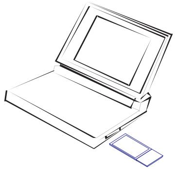
- With the PC Card's 68-pin connector facing the PCMCIA slot, label side up, slide the card completely into the slot as shown below.
Note: The PCMCIA slot allows you to "hot swap" PC Cards any time.
- Install the appropriate driver into your system. Drivers can be found on the driver CD that comes with the package. See the following section for instructions.
Driver and Utility Installation
The CD labeled "Driver and Utility CD" that comes with the package contains the software drivers and utilities available for the Wireless PC Card.
Note: You may find that the instructions here do not exactly match your version of Windows. This is because these steps and screenshots were created from Windows XP. Windows 98SE, Windows Millennium Edition, and Windows 2000 are similar, but not identical, to Windows XP.
- Place the installation CD into the CD-ROM drive. The program will auto-run.
- Windows XP will automatically install the driver.
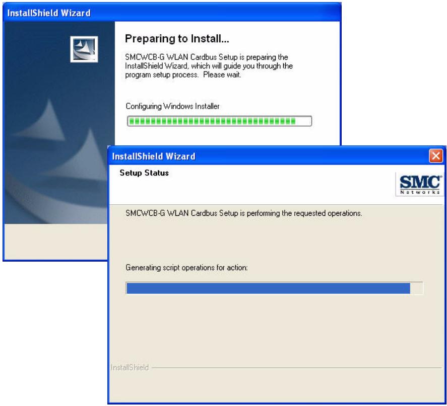
- Insert the adapter into your computer when you see the following message.

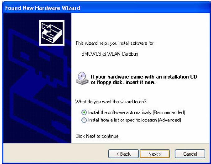
- Once the utility has been installed into your system, the Found New Hardware Wizard window will appear.
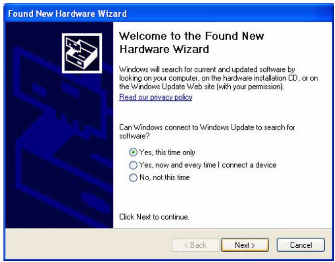
- Select Yes, this time only and click Next.
- Choose the Install the software automatically option, and click Next.
- Click Continue Anyway to proceed with the installation.
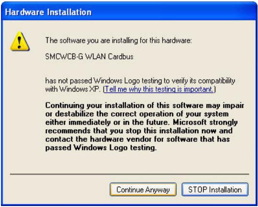
Note: Do not select STOP Installation, as this will cancel the installation process, and the drivers will not be installed properly.
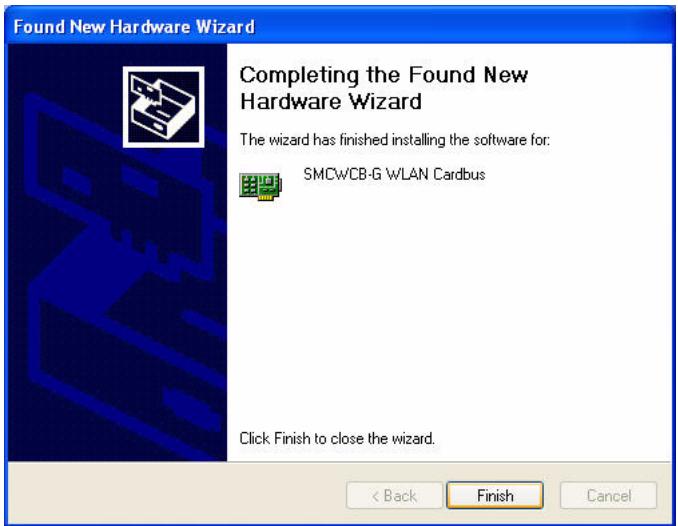
- Click Finish to exit the wizard.
- When the wizard has finished installing the driver, the following screen will appear. Select Yes, I want to restart my computer now. Click Finish and your PC will restart.
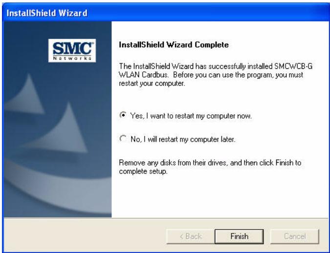
The driver and utility installation is completed. Your adapter is now ready for use.
Utility Configuration
Wireless Network Manager
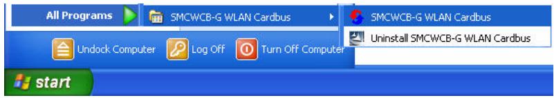
Double-click the shortcut icon on the desktop, or from the task bar to launch the utility. You can also access the utility program from the Start menu.

The configuration utility includes the following five tabs:
Configuration - Allows you to monitor network status, configure wireless adapter parameters, and access security control.
Link Information - Shows wireless adapter statistics.
IP Information — Shows Network connection information.
Site Survey — Scans/Shows all the wireless devices in range.
Version Information - Shows software version information.
At the bottom of the screen, there are three boxes that can be selected:
Wireless On/Off — Click this button to turn on/turn off the radio signal of the adapter.
Help - Click this button to view the help file.
Close — Click this button to exit the utility.
Configuration
This utility allows you to set the parameters for the wireless adapter.
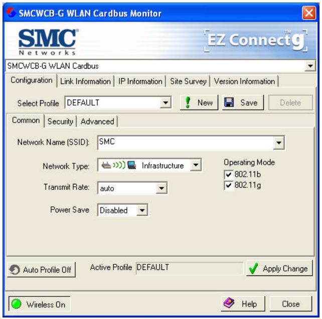
Select Profile — To specify a profile for a specific configuration of parameters.
New - Click this button to create a new profile.
Save — Click this button to save a profile after configuring the settings.
Delete — Select the profile from the drop-down menu, and click this button to delete the profile.
Auto Profile On/Off — Click this button to turn on/off the Auto Profile feature.
Active Profile — The profile settings that you are using for the current connection.
Common Tab
Network Name (SSID) — This is the Service Set ID (SSID) for the wireless network to which you want to connect.
Network Type — Set the station operation mode to Ad Hoc for network configurations that do not have an access point, or to Infrastructure for configurations with an access point.
Transmit Rate — Set the transmit rate you want from the pull-down menu. Click Apply Changes after you have made your selection. Lower settings may improve throughput in environments hostile to radio transmission.
Power Save — Enable or disable the power saving feature.
Operating Mode — The adapter supports 802.11b and 802.11g mode. Check the type of network that you want to use for your wireless connection.
Security Tab
Go to the security tab to set the security features for your adapter.
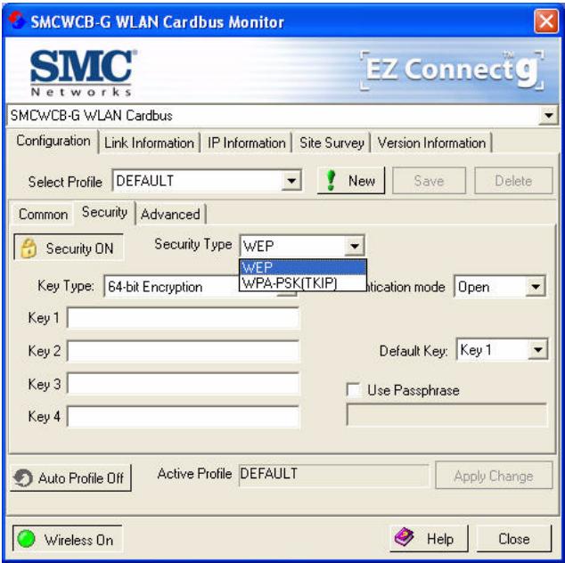

Click on this security button to turn on/turn off the security function.
Turn on the security function, and set detail parameters for your adapter.
To prevent unauthorized access, this adapter supports WEP (Wired Equivalent Privacy), and WPA (Wi-Fi Protected Access).
WEP
WEP (Wired Equivalent Privacy) implemented in the Wireless PC Card is based on the RC4 encryption algorithm. The security keys provided to ensure data confidentiality are four 10-bit keys for the 64-bit WEP setting and one 26-bit key for the 128-bit WEP setting. WEP security protects your wireless LAN against eavesdropping and unauthorized access by intruders.
Security Type — WEP (Wired Equivalent Privacy) is supported by the adapter to prevent unauthorized access.
Key Type — Choose the Key Type (ASCII or Hex) from the drop-down list.
ASCII: 13 regular text characters. Hex: 26 digits (0~9, A~F) hexadecimal characters.
Authentication Mode - Choose Open or Shared.
Default Key — Choose the Key Number that has the encryption string you prefer. If you are using a key generated from a passphrase, you must use the same passphrase and key on each station.
Use Passphrase — Check this box to auto-generate security keys for WEP encryption. Please note that you must use the same passphrase on all the stations in your network.
WPA-PSK Encryption Type
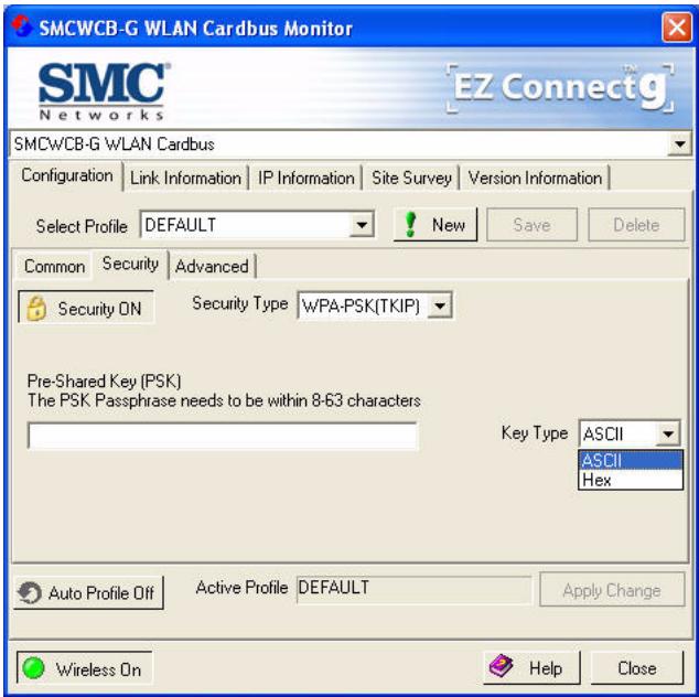
WPA (Wi-Fi Protected Access) is a stronger wireless security solution than WEP. It uses a combination of authentication and broadcast/session keys.
Pre-Shared Key (PSK) — If there is no authentication server on your SOHO network, you can issue the Pre-Shared Passphrase to the WLAN Cardbus. Please note that you must use the same passphrase on all the stations in your network.
Key Type - Choose the Key Type (ASCII or Hex) from the drop-down list.
Notes: 1. Manual Pre-Shared Key supports up to 64-Hex characters.
2. Type 8 - 63 Hex characters for the Pre-Shared Passphrase.
- Do not use a key that is long and complex for your clients to type accurately, as you might forget it.
- A Hex (hexadecimal) digit is a number or letter in the range 0-9 or A-F.
Link Information
The Link Information screen displays the information on the current wireless network to which you are connected.

Network Name — This is the Service Set ID (SSID) for the wireless network to which you want to connect.
Base Station Name ID — The MAC address of the access point to which the card is connected in an infrastructure network. In an ad hoc network, this ID is a random number generated by the first station that communicates with other stations in the network. The BSS ID of the other stations will then be set to the same value.
Channel — This is the radio channel through which the access point communicates to stations within the same network. A Basic Service Set (BSS) consists of a group of wireless PCs and an access point that is directly connected to the wired LAN. To establish an ad hoc network, make sure the "Channel" is set to the same radio channel as that used by the other wireless clients in your group. However, if you are connecting to a network via an access point, the adapter will automatically use the same channel as that used by the access point.
Note: The available channel settings are limited by local regulations that determine the number of available channels.
Current Connection Speed - Shows the speed of the current wireless connection.
Current Rx Rate - This is the transmission rate of the current connection.
Encryption — This shows the encryption type of your wireless network.
Operating Mode - This adapter supports 802.11b and 802.11g mode.
Status - This is the station status.
Country — Shows the country where you are using the adapter.
Throughput - Shows the total number of data packets transmitted and received.
Signal Strength — Shows the relative strength of the wireless connection.
Link Quality - Shows the link quality of the wireless connection.
IP Information
This screen displays IP information for your laptop. Now that you have configured your adapter to connect to wireless networks, your laptop needs to obtain new network settings. To release the current network settings, click on Release, then click on Renew to obtain new IP settings.
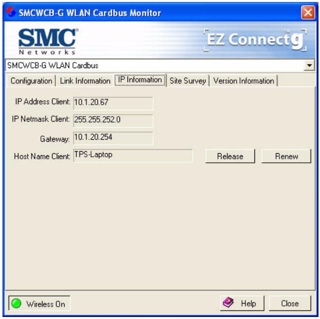
IP Address Client - Internet address of the computer.
IP Netmask Client — A netmask is a set of four number blocks separated by periods. Each number is normally represented as the decimal equivalent of an eight-bit binary number, between 0 and 255. Every IP address consists of two parts (the network address and the host number). The netmask is used to determine the size of these two parts. The positions of the bits that are set in the netmask are considered to represent the space reserved for the network address, while the bits that are cleared are considered to represent the space set aside for the host number.
Gateway — The IP address of the Gateway.
Host Name Client — The computer's name on the network.
Site Survey
The Site Survey screen displays available wireless networks. Choose one of them to connect to by double-clicking on an entry.
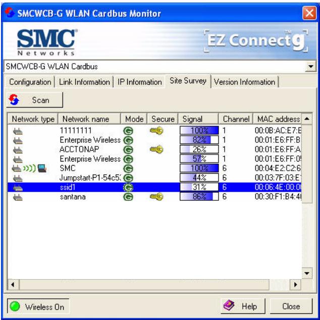
Network Type - Shows the network type. See "Configuration" on page 10.
Network name — Service Set ID (SSID) on the network. See "Configuration" on page 10.
Mode - Shows the wireless connection mode, whether it's 802.11b or 802.11g.
Secure — This shows security mechanism has been enabled. A key icon indicates the encryption function is enabled.
Signal — This shows the signal strength of the listed wireless devices.
Channel — This is the channel used for the wireless connection.
MAC address — This is the MAC address of the listed wireless devices.
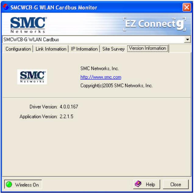
Version Information
This screen shows information on the current version of the driver and configuration utility.
Network Configuration and Planning
This Wireless Solution supports a stand-alone wireless network configuration, as well as an integrated configuration with Ethernet LANs.
The WLAN Cardbus can be configured as:
- Ad hoc for departmental or SOHO LANs
Infrastructure mode for networked LANs
Network Topologies
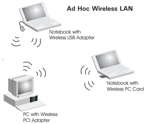
Ad Hoc Wireless LAN
An ad hoc wireless LAN consists of a group of computers, each equipped with a wireless adapter, connected via radio signals as an independent wireless LAN. Computers in a specific ad hoc wireless LAN must be configured to the same radio channel. An ad hoc wireless LAN can be used for a branch office or SOHO operation.
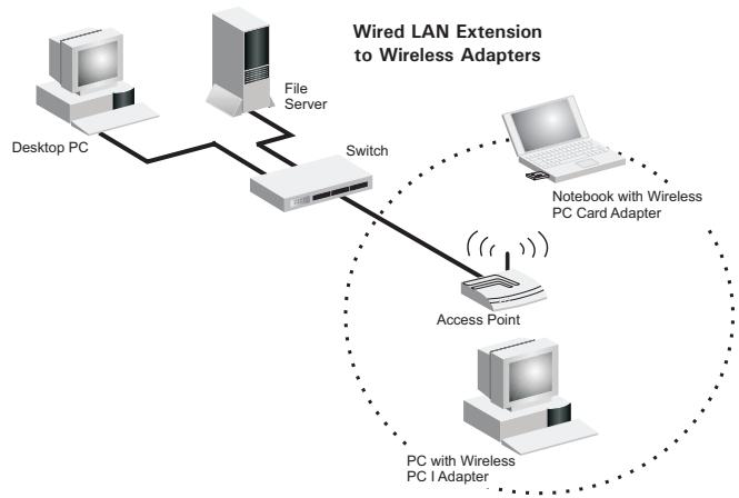
Infrastructure Wireless LAN
The WLAN Cardbus can also provide wireless workstations with access to a wired LAN. An integrated wired and wireless LAN is called an Infrastructure configuration. A Basic Service Set (BSS) consists of a group of wireless PC users, and an access point that is directly connected to the wired LAN. Each wireless PC in this BSS can talk to any computer in its wireless group via a radio link, or access other computers or network resources in the wired LAN infrastructure via the access point.
The infrastructure configuration not only extends the accessibility of wireless PCs to the wired LAN, but also extends the effective wireless transmission range for wireless PCs by passing their signal through one or more access points.
A wireless infrastructure can be used for access to a central database, or for connection between mobile workers, as shown in the following figure.
Setting the Communication Domain
Stationary Wireless PCs
The Basic Service Set (BSS) is the communication domain for each access point. For wireless PCs that do not need to support roaming, set the domain identifier (SSID) for the wireless card to theSSID of the access point to which you want to connect. Check with your administrator for theSSID of the access point to which you should connect.
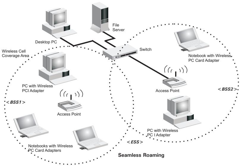
Roaming Wireless PCs
A wireless infrastructure can also support roaming for mobile workers. More than one access point can be configured to create an Extended Service Set (ESS). By placing the access points so that a continuous coverage area is created, wireless users within this ESS can roam freely. All wireless adapters and access points within a specific ESS must be configured with the sameSSID and to the same radio channel.
Troubleshooting
Check the following troubleshooting items before contacting technical support.
Adapter Installation Problems
If your computer cannot find the Wireless PC Card or the network driver does not install correctly, check the following:
- Make sure the adapter is securely seated in the PCMCIA slot. Check for any hardware problems, such as physical damage to the card's connector.
- Try the card in another PCMCIA slot. If this also fails, test your computer with another wireless card that is known to operate correctly.
Make sure your computer is using the latest BIOS. - If there are other network adapters in the computer, they may be causing conflict. Remove the other network adapters from the computer and test the wireless adapter separately.
- Check for a defective computer or PCMCIA connection by trying the adapter in another computer that is known to operate correctly.
If it still does not work, take out the wireless adapter. Then go to "Control Panel" and delete the adapter from your network configuration menu. Restart your PC and reinstall the card.
Network Connection Problems
If the Link LED on the PC Card does not light, or if you cannot access any network resources from the computer, check the following:
- Make sure the correct software driver is installed for your operating system. If necessary, try reinstalling the driver.
- Make sure the computer and other network devices are receiving power.
- The access point you want to attach to may be defective. Try using another access point.
- If you cannot access a Windows or NetWare service on the network, check that you have enabled and configured the service correctly. If you cannot connect to a particular server, be sure that you have access rights and a valid ID and password.
If you cannot access the Internet, be sure you have configured your system for TCP/IP
If your wireless station cannot communicate with a computer in the Ethernet LAN when configured for Infrastructure mode, check the following:
- Make sure the access point that the station is associated with is powered on.
- If you still cannot connect, change the access point and all the stations within the BSS to another radio channel.
- Make sure the SSID is the same as that used by the access point for a station with roaming disabled, or the same as that used by the access points in the extended service set (ESS).
Specifications
General Specifications
Functional Criteria
Network Connection
IEEE 802.11g - Wireless
Operating Range
Outdoor: Up to 400 m (1312 ft) at 54 Mbps
Indoor: Up to 180 m (590 ft) at 54 Mbps
Radio Signal
Signal Type
Direct Sequence Spread-Spectrum (DSSS)
Operating Frequency
USA (FCC) and Canada (IC): 2.412 ~ 2.462 GHz
Europe (ETSI): 2.412 ~ 2.472 GHz
Spain: 2.457 ~ 2.462 GHz
France: 2.457 ~ 2.472 GHz
Japan (STD-T66/STD-33): 2.412 ~ 2.484 GHz
Operating Channels
USA (FCC) and Canada (IC): 11 channels
Europe (ETSI): 13 channels
Spain: 2 channels
France: 4 channels
Japan (STD-T66/STD-33): 14 channels
Sensitivity
-68 dBm (typical)
Modulation
CCK, OFDM
Output Power
+9 dBm (minimum)
Physical Characteristics
Power Consumption
3.3 V, stand by mode: 0.24, sleep mode: 0.04.
transmit mode: 0.36, receive mode: 0.23
Dimensions
Type II PC Card + antenna 12.8 x 5.3 cm (5.04 x 2.09 in.)
Antenna
Built-in dual antenna
LED Indicator
Link, Activity
Host Interface
PCMCIA, Type II
Standards Conformance
Wireless Standard
IEEE 802.11b, IEEE 802.11g
Environmental
Temperature
Operating: 0 to 50^ (32 to 131^ )
Storage: -20 to 75^ (-4 to 167^ )
Humidity
5 to 90% (non-condensing)
Vibration/Shock/Drop
IEC 68-2-34, IEC 68-2-27, IEC68-2-32
Certification
CE Mark
EN 50081-1, EN 55022 Class B
EN 50082-1, EN 61000-4-2
Emissions
FCC Part 15(B), ETS 300-328, VCCI
Software Drivers
Drivers
Windows 98SE (Second Edition)
Windows Me
Windows 2000
Windows XP
Data Rate and Transmission Power
| Standard | Data Rate | Transmission Power (dBm) |
| 802.11b | 1 Mbps | 17 |
| 2 Mbps | 17 | |
| 5.5 Mbps | 17 | |
| 11 Mbps | 17 | |
| 802.11g | 6 Mbps | 16 |
| 9 Mbps | 16 | |
| 12 Mbps | 16 | |
| 18 Mbps | 16 | |
| 24 Mbps | 15 | |
| 36 Mbps | 15 | |
| 48 Mbps | 13 | |
| 54 Mbps | 13 |
Typical Receiver Sensitivity Range
Note: Frame (1000 Bytes PDUS) Packet Error Rate < 10%
| Standard | Data Rate | Modulation Rate Receiver Sensitivity (dBm) |
| 802.11b | 1 Mbps | -90 |
| 2 Mbps | -88 | |
| 5.5 Mbps | -85 | |
| 11 Mbps | -82 | |
| 802.11g | 6 Mbps | -88 |
| 9 Mbps | -87 | |
| 12 Mbps | -84 | |
| 18 Mbps | -82 | |
| 24 Mbps | -79 | |
| 36 Mbps | -75 | |
| 48 Mbps | -68 | |
| 54 Mbps | -68 |
FOR TECHNICAL SUPPORT, CALL:
From U.S.A. and Canada (24 hours a day, 7 days a week)
(800) SMC-4-YOU; Phn: (949) 679-8000; Fax: (949) 679-1481
From Europe: Contact details can be found on
www.smc-europe.com or www.smc.com
INTERNET
E-mail addresses:
techsupport@smc.com
european.techsupport@smc-europe.com
Driver updates:
http://www.smc.com/index.cfm?action tech_support_drivers_downloads
World Wide Web:
http://www.smc.com
http://www.smc-europe.com
FOR LITERATURE OR ADVERTISING RESPONSE, CALL:
U.S.A. and Canada: (800) SMC-4-YOU; Fax (949) 679-1481
Spain: 34-91-352-00-40; Fax 34-93-477-3774
UK: 44 (0) 1932 866553; Fax 44 (0) 118 974 8701
France: 33 (0) 41 38 32 32; Fax 33 (0) 41 38 01 58
Italy: 39 (0) 335 5708602; Fax 39 02 739 14 17
Benelux: 31 33 455 72 88; Fax 31 33 455 73 30
Central Europe: 49 (0) 89 92861-0; Fax 49 (0) 89 92861-230
Nordic: 46 (0) 868 70700; Fax 46 (0) 887 62 62
Eastern Europe: 34-93-477-4920; Fax 34 93 477 3774
Sub Saharian Africa: 216-712-36616; Fax 216-71751415
North West Africa: 34 93 477 4920; Fax 34 93 477 3774
CIS: 7 (095) 7893573; Fax 7 (095) 789 35 73
PRC: 86-10-6235-4958; Fax 86-10-6235-4962
Taiwan: 886-2-8797-8006; Fax 886-2-8797-6288
Asia Pacific: (65) 238 6556; Fax (65) 238 6466
Korea: 82-2-553-0860; Fax 82-2-553-7202
Japan: 81-45-224-2332; Fax 81-45-224-2331
Australia: 61-2-8875-7887; Fax 61-2-8875-7777
India: 91-22-8204437; Fax 91-22-8204443
If you are looking for further contact information, please visit www.smc.com,
www.smc-europe.com, or www.smc-asia.com.