
KY-25/Y - Portable air conditioner SUNBEAM - Free user manual and instructions
Find the device manual for free KY-25/Y SUNBEAM in PDF.

| Product type | Portable air conditioner |
| Model | KY-25/Y |
| Brand | SUNBEAM |
| Cooling capacity | 9000 BTU/h |
| Power supply | AC 115V / 60Hz / 1PH |
| Rated current | 8.2 A |
| Refrigerant | R22 / 500 g (17.6 oz) |
| Dimensions (L x D x H) | 35.1 x 35.6 x 79.8 cm |
| Net weight | 24.75 kg |
| Operating modes | Cooling, Dehumidification (Soft-Dry), Fan only, Auto |
| Fan speeds | High and Low |
| Adjustable thermostat | Yes, from 18°C to 32°C |
| Programmable timer | Yes, delayed on/off up to 24h |
| Remote control | Yes, with CR2025 battery included |
| Hot air exhaust | Via flexible hose (max length 160 cm) |
| Window installation kit | Included, adaptable to sliding windows |
| Condensation water tank | With full indicator and drainable |
| Air filter | Washable with warm water, clean every 2 weeks |
| Safety | LCDI protection (leakage current detector), grounding required |
| Warranty | 1 year for the product, 90 days for parts and labor |
| Recommended use | Residential indoor only, room about 25 m² |
Frequently Asked Questions - KY-25/Y SUNBEAM
User questions about KY-25/Y SUNBEAM
0 question about this device. Answer the ones you know or ask your own.
Ask a new question about this device
Download the instructions for your Portable air conditioner in PDF format for free! Find your manual KY-25/Y - SUNBEAM and take your electronic device back in hand. On this page are published all the documents necessary for the use of your device. KY-25/Y by SUNBEAM.
USER MANUAL KY-25/Y SUNBEAM
USE AND CARE GUIDE AND INSTALLATION INSTRUCTIONS
SECTION 1
IMPORTANT SAFETY INSTRUCTIONS
1.1 PORTABLE AIR CONDITIONER SAFETY 2
1.2 DANGER AND WARNING 2
1.3 SAVE INSTRUCTIONS FOR FUTURE REFERENCE 2-3
1.4 SPECIAL RECOMMENDATIONS 4
1.5 ELECTRICAL REQUIREMENTS 4
1.6 RECOMMENDED GROUNDING METHOD 5
1.7 LCDI PLUG (US ONLY) 5
1.8 UNPACKING YOUR PRODUCT PARTS 6
1.9 TECHNICAL SPECIFICATIONS 6
SECTION 2
A NOTE TO YOU
USER'S RECORD OF MODEL AND SERIAL NUMBER INFORMATION 7
SECTION 3
GETTING STARTED
3.1 TOOLS NEEDED 8
3.2 ACCESSORIES 8
3.3 POWER SUPPLY CORD AND RECEPTACLE. 9
3.4KNOWING YOUR PORTABLE AIR CONDITIONER 9
SECTION 4
INSTALLATION INSTRUCTIONS
4.1 PORTABLE AIR CONDITIONER INSTALLATION 10
4.2 ASSEMBLING THE AIR-EXHAUST DUCT 10
4.3 INSTALLING THE DUCTS IN THE WALL 11
SECTION 5
OPERATING YOUR PORTABLE AIR CONDITIONER
5.1 CONTROL PANEL AND OPERATING FUNCTIONS 12-13
5.2 LCD DISPLAY PANEL 13
5.3 OPERATING REMOTE CONTROL (MODEL KY-25Y ONLY) 14-16
5.4 WATER FULL INDICATION AND DRAINING 16-17
SECTION 6
CARING FOR YOUR PORTABLE AIR CONDITIONER
6.1 MAINTENANCE 18
6.2 CLEANING OR REPLACING THE AIR FILTER 18
6.3 EXTERNAL PLASTIC PARTS 18
6.4 STORAGE AT THE END OF THE COOLING SEASON 18
SECTION 7
TROUBLESHOOTING
7.1 PORTABLE AIR CONDITIONER DOES NOT WORK AT ALL 19
7.2 LOW COOLING EFFICIENCY 19-20
7.3 NOISE AND VIBRATION 20
7.4 THE UNIT TURNS ON AND OFF FREQUENTLY 20
SECTION 8
ELECTRICAL DIAGRAM. 21
SECTION 9
WARRANTY 22-23
NOTES 70-71
GUIDE D'UTILISATION ET D'ENTRETIEN ET
INSTRUCTIONS D'INSTALLION 24
SECTION 1
INSTRUCTIONS IMPORTANTES DE SECURITE
1.1 SECURITE DU CLIMATISEUR MOBILE 25
1.2 DANGER ET MISE EN GARDE 25
1.3 CONSERVEZ CES INSTRUCTIONS 25-26
1.4 RECOMMANDATIONS SPECIALES 27
1.5 NORMES ELECTRIQUES 27
1.6 METHODE DE MISE A LA TERRE RECOMMANDÉ 28
1.7 TECHNOLOGIE DE FICHE LCDI (É-U SEULEMENT) 28
1.8 DEBALLAGE DE VOS PIECES DE PRODUIT 29
1.9 SPECIFICATIONS TECHNIQUES 29
SECTION 2
MESSAGE À VOTRE INTENTION
INFORMATION, NUMERO DE MODELE ET SERIE 30
SECTION 3
PREPARATION
3.1 OUTILS NÉCESSAIRES 31
3.2 ACCESSOIRES 31
3.3 CORDON D'ALIMENTATION ET PRISE DE COURANT 32
3.4 CONNAITRE VOTRE CLIMATISEUR MOBILE 32
SECTION 4
INSTRUCTIONS D'INSTALLATION
4.1 INSTALLATION DU CLIMATISEUR MOBILE 33
4.2 INSTALLATION DES BOYAUX DANS UNE FENÉTRE/PORTE COULISSANTE 33
4.3 INSTALLATION DES BOYAUX DANS LE MUR 34
SECTION 5
FONCTIONNEMENT DU CLIMATISEUR MOBILE
5.1 PANNEAU DE COMMANDE ET FONCTIONS DE COMMANDE 35-36
5.2 AFFICHAGE LCD 36
5.3 FONCTIONNEMENT DE LA TELÉCOMMANDE (MODELE KY-25Y SEULEMENT) 37-39
5.4 INDICATION DE PLEIN D'EAU ET VIDANGER 39-40
SECTION 6
ENTRETIEN DU CLIMATISEUR MOBILE
6.1 MAINTENANCE 41
6.2 NETTOYAGE OU REMPLACEMENT DU FILTRA AIR 41
6.3PIECES EN PLASTIQUE EXTERNES 41
6.4 ENTREPOSAGE A LA FIN DE LA SAISON DE REFROIDISSEMENT 41
SECTION 7
DéPANNAGE
7.1 LE CLIMATISEUR MOBILE NE FONCTIONNE PAS 42
7.2 FAIBLE RENDEMENT DE REFROIDISSEMENT 42-43
7.3 BRUIT ET VIBRATION 43
7.4 LE CLIMATISEUR MOBILE DÉMARE ET ARRÊTER RAPIDEMENT. 43
SECTION 8
SCHEMA ELECTRIQUE 44
SECTION 9
GARANTIE 45-46
NOTER 70-71
GUIA DE USO Y CUIDADO E
USE AND CARE GUIDE AND INSTALLATION INSTRUCTIONS
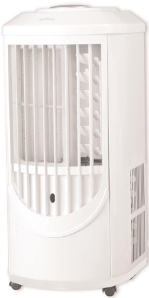
9000 BTU Portable Digital Air Conditioner with/without Remote - White Metal
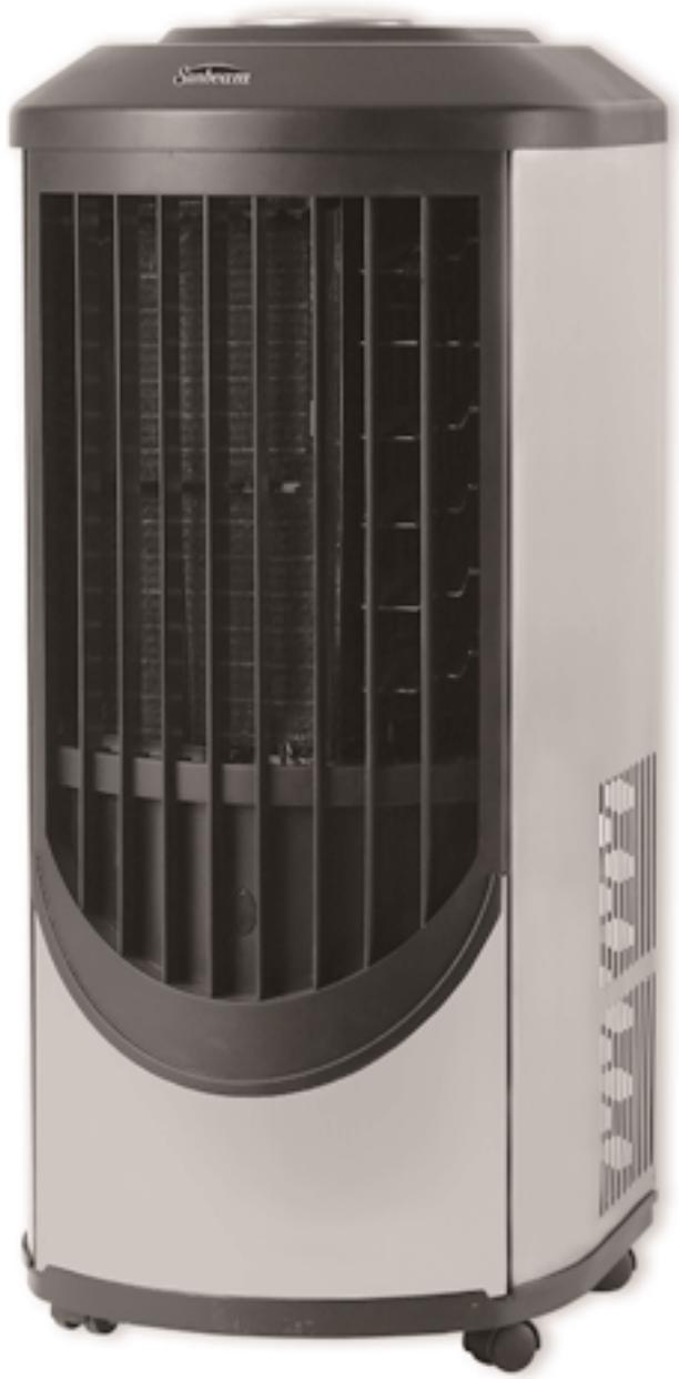
9000 BTU Portable Digital Air Conditioner with/without Remote - Stainless Steel
1.1 PORTABLE AIR CONDITIONER SAFETY
Your safety and the safety of others are very important.
We have provided many important safety messages in this manual and on your appliance. Always read and obey all safety messages.
1.2 DANGER AND WARNING

This is the safety alert symbol.
This symbol alerts you to potential hazards that can kill or hurt you and others.
All safety messages will follow the safety alert symbol and either the word "DANGER" or "WARNING".
DANGER
WARNING
These words mean:
You can be killed or seriously injured if you don't immediately follow instructions.
All safety messages will tell you what the potential hazard is, tell you how to reduce the chance of injury, and tell you what can happen if the instructions are not followed.
1.3 SAVE THESE INSTRUCTIONS FOR FUTURE REFERENCE
WARNING - To reduce the risk of fire, electrical shock, injury, or sickness when using your portable air conditioner, follow these basic precautions:
- Plug into an exclusive grounded 3-prong outlet.
- Do not remove ground prong.
- Do not use an adapter.
- Use two or more people to move or install portable air conditioner.
- Do not drink the water collected inside the cabinet.
- Follow the instructions in this manual for cleaning the unit.
- Do not insert any objects into the unit.
- Always turn off the unit before unplugging it.
- Turn off and unplug the unit before cleaning or any other kind of servicing.
- Never repair the unit or change the cord by yourself. Any repair or manipulation to the unit carried out by a non qualified individual will void the guarantee.
- Do not place objects inside the air outlet or inlet grids. Do not block air outlet and/or inlet grids.
- Do not use this unit inside closets, cabinets and/or cramped spaces between furniture.
- Do not use this unit in proximity of inflammable and/or explosive substances.
- Do not operate this unit without filters. Keep the filters clean.
- Always turn this unit on and off using the ON/OFF switch.
This portable air conditioner has been designed to create ideal climate in your room. Use it only for this specific purpose and according to the instructions in this manual.
This unit is intended for household consumer use only, and is not for commercial use.
Please use the unit in the recommended room size (refer to "Technical Specifications").
Do not place the air conditioner where furniture or other objects can obstruct the cooling airflow.
Set the unit to maximum cooling and high fan initially, then adjust the unit to a comfortable setting.
Note: It is recommended to turn on the air conditioner when the room temperature is around 75^ / 23.9^ . Do not wait until the room is excessively hot.
Note: This unit is equipped with a thermostat, and should automatically turn on when the preset temperature is reached, but only if set in the Cooling Mode. If it is set in Soft-Dry or Fan Only, the compressor will not turn on.
Please help us to help you:
- Make sure that your electric power voltage corresponds with the voltage on the nameplate of the unit.
- Keep children away from the unit.
- Check the electric cord periodically. Do not use a damaged electric cord.
- The cord length of this portable air conditioner is properly selected to reduce risk of danger. Do not use an extension cord.
- The unit should be located in a dry area.
- The unit is for indoor use only. Do not use outdoors.
- Only use the accessories supplied by the supplier. Using accessories from any source other than the supplier is dangerous and may damage the unit.
- Keep the unit away from any kind of heat source and direct sunlight - keep blinds/curtains closed during sunniest part of the day.
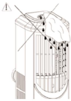
- Do not immerse the unit into water or any kind of liquid.
- Keep the unit away from any areas that have a chance of splashing water.
- To avoid the risk of shock, the unit should never be used in bathrooms, shower rooms or in any other steamy or wet areas.
- Do not use this unit at a slope - the unit is supported by four castors.
- In the event of fire, use Carbon Dioxide (CO2) extinguishers. Do not use water or powder extinguishers.
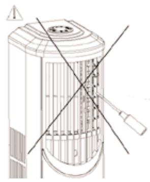
A
Do not insert any objects.
B
Do not use wet cloth to clean - only damp cloths.
C
Keep children and pets away.
D

Be cautious of where cord is placed.
Figure 1
1.4 SPECIAL RECOMMENDATIONS
- Place the portable air conditioner in a level spot. Leave at least 20^ (50.8 cm) between the unit and the wall.
- The plug should always be accessible after the unit is settled.
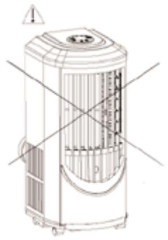
- In order to let the compressor work properly, always keep the portable air conditioner in a vertical position.
- Do not place the portable air conditioner near gas or any flammable liquids.
- Keep the unit far away from TVs or radios in order to avoid electromagnetic interference.
- Do not use any chemical sprays such as insecticides, painting or any flammable products near the unit. These chemical substances may interact with the plastic cabinet and warp it and cause electric interference.
1.5 ELECTRICAL REQUIREMENTS
WARNING
Electrical Shock Hazard
Plug into a grounded (3-prong) outlet.
Do not remove ground prong.
Do not use an extension cord.
Failure to follow these instructions can result in death, fire, or electrical shock.
In the U.S. only: If codes permit and a separate ground wire is used, it is mandatory that the ground path is adequate.
Check with a qualified electrician if you are not sure if the portable air conditioner is grounded.
A three-wire, single-phase, 60Hz AC only, electrical supply is required on a separate circuit. See model and serial label for circuit amperage required for your specific model.
If the portable air conditioner has a serial plate rating 115 Volts and up to and including 7.5 Amps, the unit may conflict with a fuse or circuit breaker with other devices.
HOWEVER, THE MAXIMUM AMPS OF ALL DEVICES ON THAT FUSE OR CIRCUIT BREAKER CAN NOT EXCEED THE AMPS OF THE FUSE OR CIRCUIT BREAKER.
If the portable air conditioner has a serial plate rating of 115 Volts and greater than 7.5 Amps it must have its own fuse or circuit breaker, and no other device or unit should be operated on that fuse or circuit breaker.
NOTE: The label lists the BTU capacity, amperage, voltage and refrigerant charge requirements.
1.6 RECOMMENDED GROUNDING METHOD
For your personal safety, this portable air conditioner must be grounded. The portable air conditioner is equipped with a power supply cord with a 3-prong grounding plug. To minimize possible electrical shock hazard, the cord must be plugged into a mating 3-prong grounding type outlet, grounded in accordance with all local codes and ordinances. If a mating 3-prong type outlet is not available, it is the consumer's responsibility to have a properly grounded, 3-prong outlet installed by a licensed installer.
It is the customer's responsibility:
- To contact a qualified electrical installer.
- To assure that the electrical installation is adequate and in conformance with National Electrical Code, ANSI/NFPA 70 – latest edition, and all local codes and ordinances.
Copies of the standards listed may be obtained from:
National Fire Protection Association
Batterymatch Park
Quincy, Massachusetts 02269.
Or your state board of electricity.
1.7 LCDI PLUG TECHNOLOGY (US ONLY)
A Leakage-Current Detect and Interrupt (LCDI) is a device that senses leakage current flowing between or from the power conductors in an appliance cord and interrupts the circuit as a predetermined level of leakage current. Since an LCDI specifically can detect a current leakage flowing to ground, it provides ground fault protection from arcing and other problems, which arise due to leakage between conductors.
LCDIs are covered under the UL 1699 standard for ARC Fault Current Interrupts, which was first published in June of 2002. LCDI devices have been mandated by the National Electric Code and Underwritten Laboratories for the cordsets on room air conditioners beginning in August 2004. Other classes of appliances will require LCDI protection in the near future.
TESTING
- Press test button, unit should trip.
- Press reset button for use.
NOTE: DO NOT USE IF ABOVE TEST FAILS.
In the event this device trips, the cause of the malfunction is to be corrected before use of the device.
CAUTION
The conductors inside this cord are surrounded by shields, which monitor leakage current. THESE SHIELDS ARE NOT GROUNDED. Periodically examine the cord for any damage. DO NOT USE this product in the event the shields become exposed.
WARNING
This product contains chemicals, including lead, known to the State of California to cause cancer, and birth defects or other reproductive harm.
Wash hands after handling.
1.8 UNPACKING YOUR PRODUCT PARTS
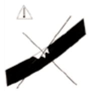
When you get this unit, please transport the product in an upright position only, and place the product on an even surface. Remove the cardboard box without turning it upside down, or laying it on its side.
Please note: If this unit is transported, it must be left in the normal up right position for at least 8 hours before using, to allow the coolant and compressor oil to settle.
a. Remove the adhesive tape on the top of the cardboard box.
b. Open the cardboard box.
c. Remove the Styrofoam packing and angle-protection board.
d. Lift and hold the unit from the Styrofoam packing base by using two people, so as not to tilt the unit.
e. Remove the plastic bag.
f. Wipe it clean if necessary.
g. Then install hot air exhaust duct for condenser side according to the installation instructions.
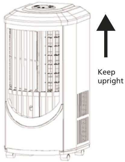
Figure 2
1.9 TECHNICAL SPECIFICATIONS
| Model # | KY-25/Y |
| Color | Stainless Steel/White Metal |
| Rate Cooling Capacity | 9000 BTU/hr |
| Voltage, Frequency, Phase | AC~115V/60Hz/1 PH |
| Rated Current | 8.2A |
| Design Pressure | Max/High 370 psi, Min/Low 150psi |
| Refrigerant, Quantity | R22/500g (17.6oz) |
| Plug Capacity | 125V/15A |
| Plug Type | 5-15P |
| Cord Length | 6.43ft/1.96M |
| Dehumidifying Amount | 25.4oz/h / 0.75L/hour |
| Air Circulation Volume | 5.67CMM/200CFM |
| Net Weight (Unit only) | 24.75 kqs/54.56 lbs |
| Dimensions | 13.8"L x 14"W x 31.42"H / 35.1cmL x 35.6cmW x 79.8cm H |
NOTE:
The above data are obtained under the following conditions:
Cooling condition: Dry bulb/Wet bulb: 95^ / 83^ (35°C/28.3°C) according to American standard 128-2001.
Operating Limits During Cooling
Maximum condition: Dry bulb/Wet bulb: 104^ F / 80^ F ( 40^ C / 26.7^ C )
Minimum condition: Dry bulb/Wet bulb: 64.4^ F / 57.2^ F ( 18^ C / 14^ C )
Thank you for buying this high quality Sunbeam® portable air conditioner. To ensure you enjoy years of trouble-free operation, we developed the Use and Care Guide. It contains valuable information about how to operate and maintain your appliance properly and safely. Please read it carefully.
Please record your model's information.
Whenever you call to request service on your appliance, you need to know your complete model number and serial number. You can find this information on the model and serial number label.
Please record the model and serial number information below. Also, record the purchase date of your appliance.
Model Number
Serial Number
Purchase Date
Company Name Star Elite, a subsidiary of Elite Group
Telephone 1-877-383-6399 (8:30am-5:30pm E.S.T.)
KEEP THIS BOOK AND
THE ORIGINAL PROOF OF PURCHASE TOGETHER IN A SAFE PLACE FOR FUTURE REFERENCE.
The label is placed on right side of unit
PLACE LABEL HERE
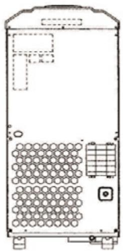
Figure 3
Back:
Technical data
Service call number and label
Back:
Warning label
3.1 TOOLS NEEDED
- Flat-blade and Phillips screwdrivers
- Gloves
- Tape measure
- Utility knife
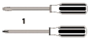
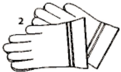
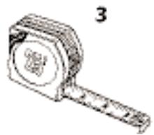
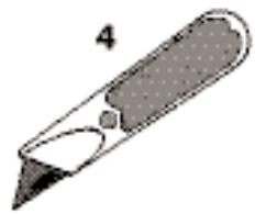
Figure 4
3.2 ACCESSORIES
- Indoor terminal end
- Exhaust duct
- Window assembly kit
- Main piece
- Window kit adapter
- Drain hose (2)
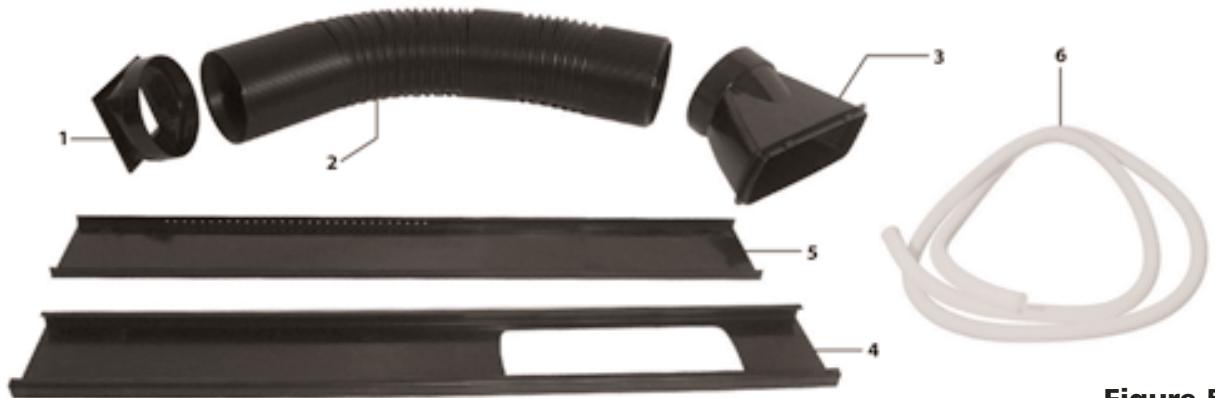
Figure 5
3.3 POWER SUPPLY CORD AND RECEPTACLE
- The plug should be well fixed and not damaged.
- Do not plug the unit with an adapter.
- Be sure the plug is fully inserted into the receptacle.
- The power cable must not come into contact with liquid of any kind; do not handle with damp or wet hands.
- Do not squeeze the cable or let it come into contact with a sharp surface.
- Do not use the power cables to drag the unit.
- Do not leave the cable in a tangled coil when it is working.
- Do not let the power cable come into contact with a hot surface.
- Do not leave the power cable in a high traffic area that will be more likely to lead to a damaged cord.
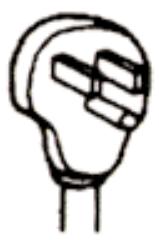
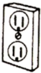
Figure 6
115 volt (103.5 min. - 126.5 max.) 0-12 amperes
15-amp time-delay fuse or circuit breaker
14 gauge copper wiring
3.4 KNOWING YOUR PORTABLE AIR CONDITIONER
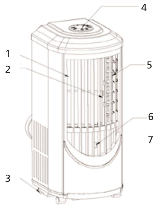
Front
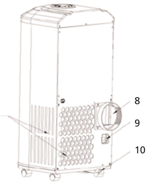
Back
Figure 7
- Air inlet
- Air filter
- Castor
- Operation panel
- Air outlet
-
Control signal receptor
-
Air inlet for condenser side
- Hot air discharging port (Use to connect air hose)
- Pump Drain
- Lower drain port
4.1 PORTABLE AIR CONDITIONER INSTALLATION
- Find a proper place for the portable air conditioner. Leave at least 20^ (50.8cm) space around the unit (Fig. 8).
When you use the unit as an air conditioner or a dehumidifier, the hot air must be exhausted out of the room to complete the air exchange of the condenser. When the unit is operating on fan, no outdoor air exchange takes place. You do not need to hookup the window kits and hot air exhaust ducts when you use the unit as a fan.
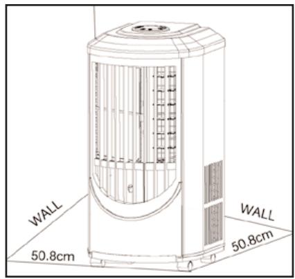
Figure 8
4.2 INSTALLING THE DUCTS IN A WINDOW/SLIDING DOOR
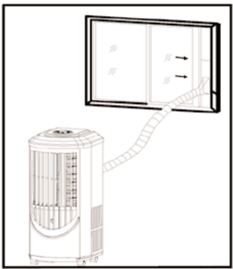
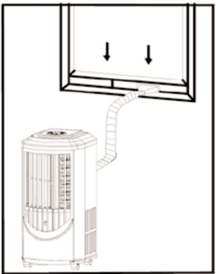
Figure 9
A) Pull out both ends of the hot air exhaust ducts for approximately 6''/15.24cm .
B) Screw the exhaust ducts clockwise with one end to the terminal end of the back of the unit and the other end to the window kit adapter.
C) Mount the terminal end of the exhaust duct to the back of the unit.
D) Open window or sliding door for approximately 5''.12.7 ~cm .
E) Adjust the length of the window kit to the same length of the window or the sliding door. Use all of the panels if necessary. Cut the window piece as needed to fit the length of your window or sliding door. Make sure that the hole on the main piece is not covered by other pieces.
F) Place the window kit in the window or sliding door. Close the window or door as far as it goes.
G) Adjust the length of exhaust duct and affix the window kit adapter onto the holes on the window kit.
NOTE: When using the window kit on a window or sliding door it will cause the window or sliding door to not be properly closed and/or locked. Additional security measurements should be taken.
4.3 INSTALLING THE DUCTS IN THE WALL
CAUTION
MANUFACTURER'S RECOMMENDATION.
BEFORE UNDERTAKING ANY INSTALLATION OF DUCTS INTO WALL, WE RECOMMEND THAT YOU CONSULT A KNOWLEDGABLE PROFESSIONAL.
A) You do not need to use window kit adapter. Mount one end of the exhaust duct into a hole of 5.6''/14.22cm in diameter in the wall; attach the other end to the back of the unit (same as above).
B) Use the exhaust outlet wall covers to cover the holes in the wall when the unit is not in use.
NOTE:
Mounting the exhaust pipe
- The supplied exhaust hose can extend from 5.75'' to 63'' / 40cm to 160cm for mounting. It is recommended that you use the shortest possible length of hose.
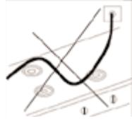
- Take care to prevent any kind of bend in the middle of the exhaust hose, as this will trap hot exhaust air, which will radiate back into the room and affect the cooling function of the unit (Fig. 10).
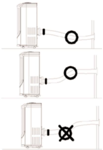
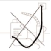
WARNING
The length of the exhaust pipe is specially designed according to the specification of this product. Do not replace or extend it with your own hose as this could cause the unit to malfunction (Fig. 11).
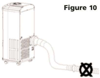
Figure 11
C) After installing the ducts, plug in the unit and turn the unit on.
5.1 CONTROL PANEL AND OPERATING FUNCTIONS
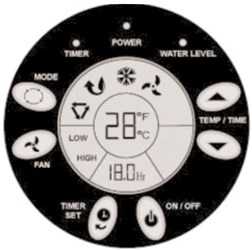
Figure 12
WARNING
If the unit is turned off during operation please wait at least three minutes before starting it again.
1) On/Off Button: Use to Start or Stop the unit.
2) Operation Mode Selection Button: Use to select the operation mode: Auto Mode, Fan-Only Mode, Soft-Dry Mode, and Cooling Mode.
3) Fan Speed Selection Button: Use to Select the fan speed: High speed or Low speed.
4) "Up" or "Down": Temperature or Time Changing Button: Use these two buttons to set to your desired temperature. The temperature unit can be on Fahrenheit or Centigrade. Press the ON/OFF Button for more than 20 seconds, then release. The temperature unit will be changed from Fahrenheit to Centigrade or vice versa. During the timer set-up, these buttons are also used to change the time.
5) Timer Setting or Cancel Button: Use to set or cancel TIMER-ON or TIMER-OFF timer. When the unit is on, the unit can be set with Timer-OFF. When the unit is off, the unit can be set with Timer-ON.
5.1 CONTROL PANEL AND OPERATING FUNCTIONS CONT'D
HOW TO SET:
When the unit is ON, press the Timer button, "3.0hr" will flash in Timer Set Display Window and the Timer Indicator will be on in the control panel. Pressing the "Up" or the "Down" button will change the time accordingly; the flashing digits will change accordingly, until your desired delay time appears. Your desired time delay will flash for ten (10) seconds. After these ten (10) seconds the digits will change to display your selected time delay. Time displayed will decrease in ten (6) minute increments.
When the unit is OFF, if it hasn't been set on Time Delay, press the Timer button. The unit enters Timer Program. Also, the "3.0Hr" will flash in Timer Set Display Window and the Timer Indicator will be on in the control panel. Press the "Up" or the "Down" button to set to your desired time. When you are setting the time, the other settings like Operation Mode, Fan Mode, or Set Temperature, will also display. Ten (10) seconds later, these modes will disappear but be remembered by the Main Controller.
HOW TO CANCEL:
When the unit is set with the TIMER-OFF or the TIMER-ON procedures, press the Timer button to check the Timer set time, then press within ten (10) seconds to cancel the timer setting.
5.2 LCD DISPLAY PANEL

Auto mode

Fahrenheit mode

Soft-dry mode

Centigrade mode

Cooling mode

Fan-only mode
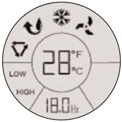
Figure 13
5.3 OPERATING REMOTE CONTROL (MODEL KY-25Y ONLY)
The functionality of the six (6) buttons on the Remote Control are identical to the functionality of the buttons on the Control Panel. Icons for certain buttons may differ slightly. The Remote Control uses the lithium batteries, Model: CR2025 (Included). Install the batteries before using the Remote Control.
You can operate the unit either on the Control Panel or with the Remote Control.
COOLING OPERATION:
1) Plug the Power Cord into the power outlet.
2) Turn on the unit by pressing the ON/OFF Button on the control panel or the remote control.
3) Press the Mode Button on the remote control 品 or the control panel until the symbol appears on the display.
4) Set the room temperature to your desired room temperature with the temperature ranges from 64^-90^ / 18^-32^ . Recommended temperatures are 80^-84^ / 27^-29^ .
5) Select the fan speed by pressing the Fan Button on either the remote control or the control panel.
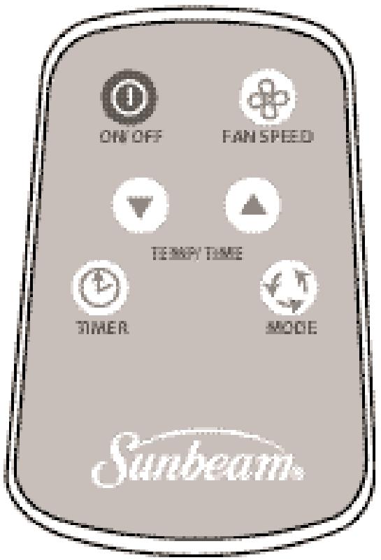
Figure 14
SOFT-DRY OPERATION:
1) Plug the Power Cord into the power outlet.
2) Turn on the unit by pressing the ON/OFF Button on the control panel or the remote control.
3) Press the Mode Button on the remote control 心 or the control panel 心 until the 心 symbol appears on the display.
4) Set the room temperature to an appropriate temperature.
5) Keep the windows and the doors closed to aid the effectiveness of the unit in removing the moisture from the room.
NOTE: The unit will not perform its dehumidifying function when the room temperature is lower than 64^ / 18^ . Soft-Dry Mode is a very gentle cooling operation consisting primarily of dehumidifying. It will not lower the room temperature very much. The indoor unit Fan always runs at Low speed.
5.3 OPERATING REMOTE CONTROL (MODEL KY-25Y ONLY) CONT'D...
FAN-ONLY OPERATION:
1) Plug the Power Cord into the power outlet.
2) Turn on the unit by pressing the ON/OFF Button on the control panel or the remote control.
3) Press the Mode Button on the remote control or the control panel until the symbol appears on the display.
4) Select the fan speed by pressing the Fan Button on either the remote control or the control panel.
When in Fan-Only Mode, the exhaust duct is not needed, and the compressor and condenser side fan motor will not work. Temperature setting has no meaning and no controlling action.
AUTO OPERATION:
1) Plug the Power Cord into the power outlet.
2) Turn on the unit by pressing the ON/OFF Button on the control panel or the remote control.
3) Press the Mode Button on the remote control 或 or the control panel until the symbol appears on the display.
4) Set the room temperature to your desired room temperature with "Down" or "Up" Temperature Changing Buttons.
5) Select the fan speed by using the FAN Speed button on either the remote control or the control panel.
When in the AUTO mode, the unit will be in Fan-Only Mode when the room temperature is below 81^ / 27^ . It will operate in Cooling Mode when the room temperature is above 81^ / 27^ .
TIMER-ON PROGRAM SETTING:
How to set:
When the unit is off, you can set the timer to let the unit automatically turn on.
1) Press the Timer Set Button on the control panel or on the remote control. The "3.0Hr" will flash in Timer Set Display Window, and the Timer Indicator, on the control panel, will turn on. The other mode settings like Operation Mode, Fan Mode, Set Temperature Mode, will also be displayed, allowing you to change or set them as well.
2) Press the "Down" button or the "Up" button to change the Timer delay time to your desired time.
3 After a ten (10) second delay (not pressing on any buttons), the digit will change to display, and the other setting modes will disappear. Now the Timer Setting Process is complete. Once some time has passed, the digits will decrease in 6 minute increments.
When the digits decrease to ZERO and disappear, the unit will start to run automatically according to your setting.
How to cancel:
When the unit is set with TIMER-ON while it's off, press the Timer Button on the control panel or on the remote control to check the Timer setting and the Time digits will flash. Press the
TIMER button again; this will cancel the timed setting. The Timer Indicator on the control panel will then turn off.
5.3 OPERATING REMOTE CONTROL (MODEL KY-25Y ONLY) CONT'D...
TIMER-OFF PROGRAM SETTING:
How to set:
When the unit is on, after being set with the TIMER-OFF, the unit will stop after your set delay time.
1) Press the Timer Button on the control panel or on the remote control. Now the TIMER INDICATOR "30Hr" will flash in the Timer Set Display Window, and the Timer Indicator on the control panel will be on.
2) Press the "Down" button or the "Up" button to change the delay time to your desired time.
3) After a 10 second delay (not pressing on any buttons), the digits will change to display. The Timer Setting Process is complete. Once some time has passed, the digits will decrease in 10 minute increments.
How to cancel:
When the unit is set with TIMER-OFF, while the unit is on, first press Timer Button on the control panel or on the remote control to check the Timer setting and the Time digits will flash. Press the TIMER button again and the Timer Setting will be cancelled. The Timer Indicator on the control panel will then turn off.
5.4 WATER FULL INDICATION AND DRAINING
WATER FULL INDICATION:
Under normal temperatures, water will evaporate without the need to drain it from the unit.
The WATER FULL indicator light will turn on during days of extreme humidity, when in Cooling Mode or Soft-Dry Mode. When the WATER FULL indicator light turns on, it means that the water reservoir is full. The compressor will stop working, but both of the two fan motors will continue working. The unit will drain excess water once a Drain Hose or Garden Hose is connected to it. When the WATER FULL indicator light disappears, the compressor will start to work again.
DRAINING:
Only in extreme humidity
1) To add a Drain Hose or Garden Hose you must first stop the unit by turning it OFF. You must then unscrew the Drain Cap on the Pump Drain before inserting the white Drain Hose (5'3''/1.61m) provided with your unit. (Attention: there may be some water behind the Drain Cap. Have a bowl or receptacle ready to catch any runoff).
After connecting the Drain Hose to the inner spout (Fig.15) of the Pump Drain, ensure that the other end is placed in a bucket or receptacle for gathering the excess water. Check the water level in the receptacle to avoid any possibilities of leaking.
Instead of the Drain Hose provided with your unit, you may also use a Garden Hose (in cases where you require a distance longer than that provided by the Drain Hose). In this case screw the female end of a Garden Hose to the outer threaded spout of the Pump Drain (Fig.16). After connecting the Garden Hose, place the outer end outside of the house or in a convenient area where the excess water can be safely expelled.
2) Now, turn the unit ON and back to its previous setting (either COOLING or SOFT-DRY mode). The Pump Drain will begin to pump water out of the unit. (If using a water bucket, please check the expelled water level to ensure that it does not over flow.) Once the WATER FULL light indicator turns off ... the DRAIN cycle is complete. At this point, turn OFF the unit, remove the Drain Hose or Garden Hose and then turn the unit back ON and to its previous setting (COOLING or SOFT-DRY mode).
5.4 WATER FULL INDICATION AND DRAINING CONT'D...
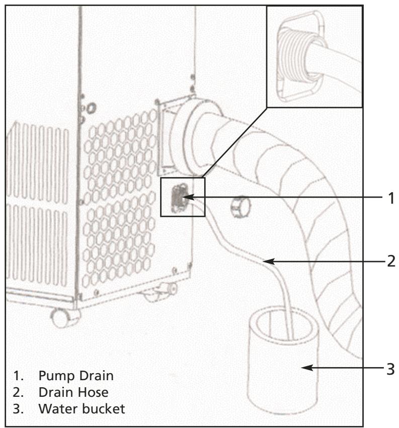
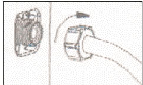
Figure 15
Figure 16
NOTE: The cooling efficiency of your unit will be affected if the Drain Hose or the Garden Hose is always attached to it. The Drain Hose or Garden Hose must be used only when the WATER FULL indicator is on.
MAKE SURE THAT THE DRAIN CAP IS REINSTALLED PROPERLY TO PREVENT LEAKING.
6.1 MAINTENANCE
WARNING
- Make sure the power supply is switched off and the plug is pulled out of the power outlet before performing any maintenance activities.
- Do not immerse the unit in water or other liquids.
- Do not pour liquids into the unit.
Take special precaution to avoid the sharp cutting edges of some parts. - Do not use any kind of chemical solvents to clean the unit, as they may deform the unit cabinet.
6.2 CLEANING OR REPLACING THE AIR FILTER
If the air filter is blocked with a lot of dust, the volume of airflow will be reduced and the cooling effect will be lower. It is recommended to clean the filter once every two weeks or as needed.
A) Pull out the filter from the filter compartment in front of the unit.
B) Wash the air filter by immersing it gently into warm (about 104^ / 40^ ) water with a gentle detergent. Rinse the filter and dry it thoroughly in a shaded place.
C) Place the filter back into the filter compartment after it is thoroughly dried.
D) If the filter is torn or unusable, order a new filter by calling the Sunbeam Customer Service department at 1-877-383-6399 (8:30am-5:30pm E.S.T.).
6.3 EXTERNAL PLASTIC PARTS
A) Keep the unit from being exposed directly to the sun.
B) Clean the surface with a damp cloth.
C) For the Stainless Steel finished models, a good quality stainless steel cleaner should be used.
6.4 STORAGE AT THE END OF THE COOLING SEASON
A) On a warm day, turn the unit on in the FAN-ONLY Mode for a couple of hours so that the inside can dry out completely.
B) Turn off the unit and unplug the unit.
C) Empty the residual condensed water by unplugging the LOWER WATER DRAINAGE CAP at the back towards the bottom of the unit. After connecting the 12^ / 3.65m white Drain Hose, ensure that the other end is in a bucket or receptacle for gathering the water.
D) Discharge the Hot air duct and shorten it and pack it in the box.
E) Clean the filter and dry it completely before fitting back in place.
F) Cover the appliance to protect it from dust. It is recommended that the unit be put back into its original box and package.
G) The unit should be stored in a cool dry place. Do not stack heavy objects on the top of the unit.
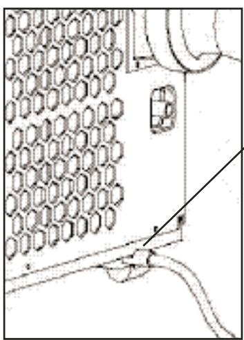
Figure 17
Lower drain port
You can solve many common portable air conditioner problems easily, saving you the cost of a service call. Try the suggestions below to see if you can solve your problem without outside help.
7.1 PORTABLE AIR CONDITIONER DOES NOT WORK AT ALL
| Check if... | Then... |
| The local power has failed. | Wait until local power is restored. |
| The plug is loose. | Firmly insert the plug into the wall socket. |
| The power fuse is burned. | Replace the fuse. Make sure the portable air conditioner is plugged into an exclusive properly grounded outlet as described in the Installation Instructions. |
| The water tank is full. | Drain out the water (see page 16). |
| LCDI plug has tripped. | Press the RESET button on the LCDI plug. |
| The time is set properly. | Set the proper time. |
| Water-Full Indicator is displayed. | Empty the water inside the unit (see page 16). Wait 1 hour to let the condenser side fan blow out the water. |
7.2 LOW COOLING EFFICIENCY
| Check if... | Then... |
| The air inlet or outlet is closed. | Open the air inlet and outlet. |
| There is a heat source in the room. | Move the heat source away. |
| The air filter is dirty. | Clean the air filter, referring to "Cleaning the Air Filter" section. |
| The cooling temperature is set properly. | Set the cooling temperature at a proper level. |
| The indoor fan is set at a low speed. | Set the indoor fan speed higher. |
7.2 LOW COOLING CONT'D
| Check if... | Then... |
| The outside temperature is lower than 64°F (18°C). | Do not operate your portable air conditioner in cooling mode when the outside temperature is lower than 64°F (18°C). |
| Windows and doors are open. | Close all doors and windows. |
| Unit is set at dehumidifying mode. | Set unit at cooling mode. |
7.3 NOISE AND VIBRATION
| Check if... | Then... |
| There is noise from the unit. | If the sound is not too high and comes from the compressor, the evaporator or the condenser, it is normal. |
| The unit is vibrating while working. | The unit is not on a flat place. Put the unit on a solid, flat place. |
7.4 THE UNIT TURNS ON AND OFF FREQUENTLY
| Check if... | Then... |
| The voltage of the local power is normal. | Wait until the local power is normal. |
| The hot air discharging port is properly installed. | Install the hot air discharging port properly as instructed in this manual. |
| The outside temperature is extremely hot. | Set the fan on high speed to let air pass cooling coils faster. |
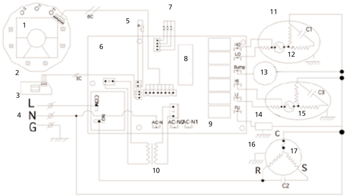
Figure 17
C1: Running capacitor for Fan Motor of condenser side
C2: Running capacitor for compressor
C3: Running capacitor for Fan Motor of evaporator side
- LCD Display
- Operation Panel PCB
- Receptor PCB
- Power Supply
- Room temperature sensor
- Main Control PCB
- Water level detector
- Microchip processor
- Main controller PCB
- Transformer
- Fan motor for condensor side
- Cut-off
- Water pump
- Motor for evaporator side
- Cut-off
- Compressor
- Protector
STAR ELITE/ELITE GROUP
LIMITED ONE-YEAR WARRANTY POLICY
EFFECTIVE:APRIL 2005
LIMITED WARRANTY
Star Elite/Elite Group, Inc. (hereinafter referred to as SE/EG) hereby warrants, subject to the conditions herein stated in the paragraphs below, that should this product become defective by reason of improper workmanship or material defect during the specified warranty period, SE/EG will repair or refund the same effecting all necessary parts replacements. Transportation charges on parts submitted for repair or refund, under this warranty, must be borne by the purchaser.
THERE IS NO OTHER EXPRESS WARRANTY. IMPLIED WARRANTYES, INCLUDING THOSE OF MERCHANTABILITY AND FITNESS FOR A PARTICULAR PURPOSE, ARE LIMITED TO THE TIME PERIOD SPECIFIED, OR TO THE EXTENT PERMITTED BY LAW. ANY AND ALL IMPLIED WARRANTY ARE EXCLUDING. LIABILITY FOR CONSEQUENTIAL DAMAGES UNDER ANY AND ALL WARRANTYES ARE EXCLUDING TO THE EXTENT EXCLUSION IS PERMITTED BY LAW.
WARRANTY PERIOD
| Product | Consumer/Residential Use Only |
| Air Conditioner | 1 Year |
| Dehumidifier | 1 Year |
| Wine cooler/Beverage Center | 1 Year |
| Ice Maker | 1 Year |
| Mini & 16L Thermoelectric Cooler/Warmers | 1 Year |
| Electric fireplace/Heater | 1 Year |
| Parts & Labor | 90 Days |
SE/EG warrants that from the date of purchase, this product will be free from mechanical defects for a period of one (1) year and a period of ninety (90) days on parts and labor. SE/EG, at its option, will repair or refund this product found to be defective during the warranty period. If the product is no longer available, SE/EG may refund your purchase (at a depreciated value), with an original proof of purchase. This is yourexclusive warranty.
CONDITIONS
ORIGINAL SALES RECEIPT: This warranty is valid for the original retail purchaser from the date of initial retail purchase and is not transferable. Keep the original sales receipt. Proof of purchase is required to obtain warranty service and/or refund. SE/EG dealers, service centers, or retail stores selling SE/EG products do not have the right to alter, modify or in any way, change the terms and conditions of this warranty.
.... Continued on Next Page...
WARRANTY REGISTRATION IS NOT NECESSARY TO OBTAIN WARRANTY ON SE/EG PRODUCTS. SAVE YOUR PROOF OF PURCHASE RECEIPT. IF YOU DO NOT PROVIDE PROOF OF THE INITIAL PURCHASE DATE AT THE TIME WARRANTY SERVICE IS REQUESTED, THE MANUFACTURING DATE OF THE PRODUCT WILL BE USED TO DETERMINE THE WARRANTY
DEPRECIATION: Any unit being diagnosed as non-functional and warranting an exchange, during the existing warranty period, will be subject to an appropriate depreciation or user fee.
ABOUT YOUR PRODUCT WARRANTY: We welcome warranty repair and apologize to you for being inconvenienceed. Any Authorized service dealer may perform warranty repairs. Most warranty repairs are handled routinely, but sometimes requests for warranty service may not be appropriate. For example, warranty service would NOT apply if the product damage occurred because of misuse, lack of routine maintenance, shipping, handling, warehousing or improper installation. Similarly, the warranty is void if the manufacturing date or the serial number on the product has been removed or the equipment has been altered or modified. During the warranty period, the Authorized service dealer, at its option, will repair or refund any part that, upon examination, is found to be defective under normal use and service.
NORMAL WEAR: This warranty does not cover normal wear of parts or damage resulting from any of the following: Negligent use or misuse of the product; Improper voltage or current; Use contrary to the operating instructions; Deviation from instructions regarding storage and transportation; Disassembly; Repair or alteration by anyone other than SE/EGor a SE/EG Authorized service center. Further, the warranty does not cover Acts of God, such as fire, flood, hurricanes and tornadoes.
SE/EG shall not be liable for any incidental or consequential damages caused by the breach of any express or implied warranty. Except to the extent prohibited by applicable law, any implied warranty of merchantability or fitness for a particular purpose is limited in duration to the duration of the above warranty. Some states, provinces or jurisdictions do not allow the exclusion or limitation of incidental or consequential damages or limitations on how long an implied warranty lasts, so the above limitations or exclusion may not apply to you. This warranty gives you specific legal rights, and you may also have other rights that vary from state to state or province to province.
HOW TO OBTAIN WARRANTY SERVICE: You must contact SE/EG Customer Service/Technical Support at our toll-free number 1-877-383-6399. A Customer Service/Technical Support representative will attempt to resolve warranty issues over the phone. If telephone resolution is not possible, the Customer Service/Technical Support representative will require your assistance in performing routine diagnostic procedures. This warranty is effective for the time periods listed above and subject to the conditions provided for in this policy. For warranty service, find the nearest Authorized Service Dealer by calling 1-877-383-6399. Warranty service may only be performed by a Star Elite, Inc./Elite Group, Inc. Authorized Service Dealer.
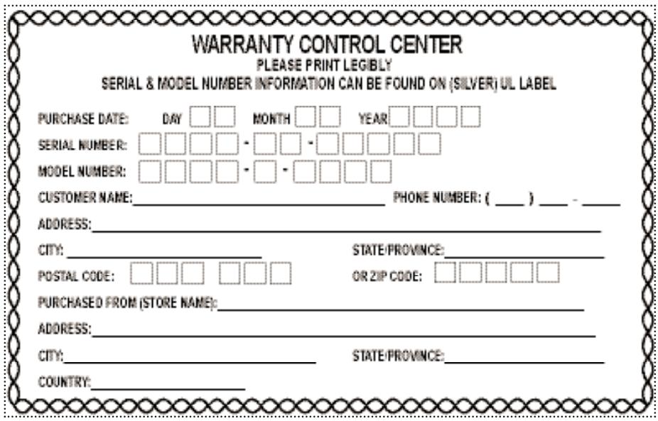
WARRANTY CONTROL CENTER

1175 Place Du Frere Andre
Montreal, Quebec, Canada H3B 3X9
1-877-383-6399 (8:30am- 5:30pm E.S.T)
Stamp Here
GUIDE D'UTILISATION ET D'ENTRETIEN ET INSTRUCTIONS D'INSTALLATION
National Fire Protection Association
Batterymatch Park
Quincy Massachusetts 02269.
1-877-383-6399 (8:30am-5:30pm E.S.T)
CONSERVEZ CE GUIDE ET
LE PREUVE D'ACHAT ENSEMBLE DANS UN ENDROIT SÜR POUR RÉFERENCE ULTERIEURE.
RECOMMANDATION DU MANUFACTURIER.
AVANT D'ENTREPRENDRE Toute INSTALLATION DE CONDUITS DANS LE MUR, NOUS RECOMMANDONS QUE VOUS CONSULTIEZ UN PROFESSIONNEL BIEN INFORMÉ
Mode SEC-DOUX [Soft-dry mode]

Montreal, Quebec, Canada H3B 3X9
1-877-383-6399 (8h30- 17h30 H.N.E.)
National Fire Protection Association
Batterymatch Park
Quincy Massachusetts 02269.
© 2006 Sunbeam Products, Inc., doing business as Jarden Consumer Solutions.
All rights reserved.

s a registered trademark of Sunbeam Products, Inc.
Manufactured in China for Star Elite, a division of the Elite Group, Inc., Quebec, Canada, H3B 3X9.
© 2006 Sunbeam Products, Inc., exploiterée sous la raison sociale Jarden Consumer Solutions.
Montreal, Quebec, Canada
H3B 3X9
Toll Free Tel / Tél. sans frais / Tel sin cargo:
1-877-383-6399
8:30am-5:30pm E.S.T
(8h30-17h30 H.N.E)
(8:30am-5:30pm E.S.T.E.)
- SECTION 1
- IMPORTANT SAFETY INSTRUCTIONS
- SECTION 2
- A NOTE TO YOU
- SECTION 3
- GETTING STARTED
- SECTION 4
- INSTALLATION INSTRUCTIONS
- SECTION 5
- OPERATING YOUR PORTABLE AIR CONDITIONER
- SECTION 6
- CARING FOR YOUR PORTABLE AIR CONDITIONER
- SECTION 7
- TROUBLESHOOTING
- SECTION 8
- SECTION 9
- INSTRUCTIONS IMPORTANTES DE SECURITE
- MESSAGE À VOTRE INTENTION
- PREPARATION
- INSTRUCTIONS D'INSTALLATION
- FONCTIONNEMENT DU CLIMATISEUR MOBILE
- ENTRETIEN DU CLIMATISEUR MOBILE
- DéPANNAGE
- USE AND CARE GUIDE AND INSTALLATION INSTRUCTIONS
- PORTABLE AIR CONDITIONER SAFETY
- DANGER AND WARNING
- DANGER
- WARNING
- SAVE THESE INSTRUCTIONS FOR FUTURE REFERENCE
- Please help us to help you:
- SPECIAL RECOMMENDATIONS
- ELECTRICAL REQUIREMENTS
- Electrical Shock Hazard
- RECOMMENDED GROUNDING METHOD
- LCDI PLUG TECHNOLOGY (US ONLY)
- TESTING
- NOTE: DO NOT USE IF ABOVE TEST FAILS.
- CAUTION
- UNPACKING YOUR PRODUCT PARTS
- TECHNICAL SPECIFICATIONS
- NOTE:
- Operating Limits During Cooling
- KEEP THIS BOOK AND
- TOOLS NEEDED
- ACCESSORIES
- POWER SUPPLY CORD AND RECEPTACLE
- KNOWING YOUR PORTABLE AIR CONDITIONER
- PORTABLE AIR CONDITIONER INSTALLATION
- INSTALLING THE DUCTS IN A WINDOW/SLIDING DOOR
- INSTALLING THE DUCTS IN THE WALL
- MANUFACTURER'S RECOMMENDATION.
- BEFORE UNDERTAKING ANY INSTALLATION OF DUCTS INTO WALL, WE RECOMMEND THAT YOU CONSULT A KNOWLEDGABLE PROFESSIONAL.
- Mounting the exhaust pipe
- CONTROL PANEL AND OPERATING FUNCTIONS
- CONTROL PANEL AND OPERATING FUNCTIONS CONT'D
- HOW TO SET:
- HOW TO CANCEL:
- LCD DISPLAY PANEL
- OPERATING REMOTE CONTROL (MODEL KY-25Y ONLY)
- COOLING OPERATION:
- SOFT-DRY OPERATION:
- OPERATING REMOTE CONTROL (MODEL KY-25Y ONLY) CONT'D...
- FAN-ONLY OPERATION:
- AUTO OPERATION:
- TIMER-ON PROGRAM SETTING:
- When the digits decrease to ZERO and disappear, the unit will start to run automatically according to your setting.
- TIMER-OFF PROGRAM SETTING:
- WATER FULL INDICATION AND DRAINING
- WATER FULL INDICATION:
- DRAINING:
- Only in extreme humidity
- WATER FULL INDICATION AND DRAINING CONT'D...
- MAINTENANCE
- CLEANING OR REPLACING THE AIR FILTER
- EXTERNAL PLASTIC PARTS
- STORAGE AT THE END OF THE COOLING SEASON
- PORTABLE AIR CONDITIONER DOES NOT WORK AT ALL
- LOW COOLING EFFICIENCY
- LOW COOLING CONT'D
- NOISE AND VIBRATION
- THE UNIT TURNS ON AND OFF FREQUENTLY
- STAR ELITE/ELITE GROUP
- LIMITED ONE-YEAR WARRANTY POLICY
- EFFECTIVE:APRIL 2005
- LIMITED WARRANTY
- CONDITIONS
- GUIDE D'UTILISATION ET D'ENTRETIEN ET INSTRUCTIONS D'INSTALLATION
- CONSERVEZ CE GUIDE ET
- RECOMMANDATION DU MANUFACTURIER.
- AVANT D'ENTREPRENDRE Toute INSTALLATION DE CONDUITS DANS LE MUR, NOUS RECOMMANDONS QUE VOUS CONSULTIEZ UN PROFESSIONNEL BIEN INFORMÉ
Brand : SUNBEAM
Model : KY-25/Y
Category : Portable air conditioner