
CALIFORNIA CLASSIC - Motorcycle MOTO GUZZI - Free user manual and instructions
Find the device manual for free CALIFORNIA CLASSIC MOTO GUZZI in PDF.

User questions about CALIFORNIA CLASSIC MOTO GUZZI
0 question about this device. Answer the ones you know or ask your own.
Ask a new question about this device
Download the instructions for your Motorcycle in PDF format for free! Find your manual CALIFORNIA CLASSIC - MOTO GUZZI and take your electronic device back in hand. On this page are published all the documents necessary for the use of your device. CALIFORNIA CLASSIC by MOTO GUZZI.
USER MANUAL CALIFORNIA CLASSIC MOTO GUZZI
First edition: January 2006
Reprint:
Produced and printed by:
VALLEY FORGE DECA
Ravenna, Modena, Torino
DECA S.r.l.
Registered Office and Administrative Headquarter
Via Vincenzo Giardini, 11
48022 Lugo (RA) - Italia
Tel. +39-0545216611
Fax+39-0545216610
E-mail: deca@vftis.spx.com
www.vftis.com
On behalf of:
Moto Guzzi S.p.A.
via E.V.Parodi,57
23826 Mandello del Lario (LECCO) - Italia
Tel. +39-0341 70911
Fax+39-0341709220
www.motoguzzi.it
The illustrations and description in this booklet are indicative only and the manufacturer reserves itself the right to introduce any modification it may deem necessary for better performance or for constructive or commercial reasons without prior notice.
First of all we wish to thank you for choosing this motorcycle of our production.
By following the instructions outlined in this manual you will ensure your bike a long and troublefree life.
Before riding, please read thoroughly this manual in order to know your motorcycle's features and how to operate it safely.
All major checking and overhaul jobs are best carried out by our dealers who have the necessary facilities to quickly and competently repair your Moto Guanzi.
Repairs or adjustments by any other than a Guzzi dealer during the warranty period could invalidate the warranty right.
Monsieur:
IMPORTANT - The text is supplemented with schematic illustrations for quick reference and better understanding of the subjects concerned. This manual contains some special remarks:
A Accident prevention rules for the mechanic and for the personnel working nearby.
Possibility of damaging the motorcycle and/or its components.
Additional information concerning the job being carried out.
Pedale commande freno
anteriori sinistro e
posteriore 76
Leva commande cambio .... 78
Tappo serbatoio
carburante 80
Basic safety ryles. 18
Clothing 32
Accessories 36
Load 40
SPECIFICATIONS 48
Engine 48
Transmission 49
Frame 49
FRAME AND ENGINE
NUMBERS 60
Spare Parts 62
INSTRUMENTS AND
CONTROLS 64
Control panel 64
Automatic light control .... 68
Horn button, passing and
direction indicators. 70
Starter button and engine
stop switch 72
Handgrip heating switch
(CALIFORNIA
TOURING only) 74
Throttle twist grip 74
Clutch lever 74
Brake lever, r/h front
brake 76
“CHOKE” control 76
Brake pedal for left front
brake and rear brake 76
Gear change pedal 78
Fuel filler cap 80
Fuse box 84
Steering damper 88
Side bags and top-case ... 90
(CALIFORNIA TOURING) 90
Seat lock 92
Helmet holder 94
Documents and objects
holder 94
Side stand 96
12V power outlet 98
RIDING YOUR
MOTORCYCLE 100
Preliminary checks 100
Cold starting 100
Warm start 102
On the way. 102
Stopping the motorcycle. 104
Parking 106
RUNNING-IN 109
MAINTENANCE AND
ADJUSTMENTS 112
Adjusting the clutch lever 112
Adjusting the brake pedal
of rear and left-hand front
brakes 114
Checking brake pads
wear 116
Checking brake disks .... 116
Checking the brake fluid in
the master cylinder
reservoir 118
Adjustable telescopic fork
adjustment 124
Rear shock-absorber
adjustment 126
REMOVING THE WHEELS .. 130
Front wheel 130
WARNING FOR WHEELS WITH
SPIKES 134
Max. allowed load 134
Rear wheel 136
Tyres 140
Tyre fitting. 142
SERVICE SCHEDULE 145
CLEANING-STORING.....148
Cleaning 148
Storage 150
CLEANING THE
WINDSCREEN 152
LUBRICATION 154
Engine lubrication 154
Changing the filter
cartridge and cleaning the
mesh filter 158
Gearbox lubrication 160
Rear transmission box
lubrication 162
Front fork oil change..... 164
Greasing 164
INJECTION-IGNITION
SYSTEM 166
Description of the system 168
Operation phases 170
Adjusting the idle setting. 176
Changing the air filter..... 178
Spark plugs 180
ELECTRICAL EQUIPMENT 184
Battery 186
Replacing bulbs 188
Adjusting the headlight
beam 196
Bulbs 198
WIRING DIAGRAM 201
Key to wiring diagram .... 201
Wiring diagram 207
14 TABLE DES MATIERES
CONDUITE EN SECURITE ... 19
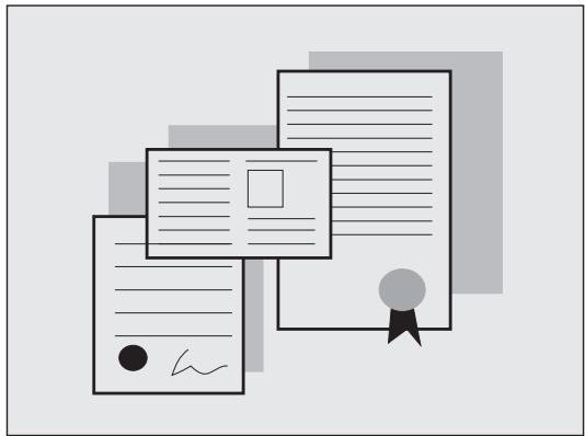
To drive the vehicle it is necessary to be in possession of all the requirements prescribed by law (driving licence, minimum age, psychophysical ability, insurance, state taxes, vehicle registration, number plate, etc.).
Gradually get to know the vehicle by driving it first in areas with low traffic and/or private areas.
CONDUITE EN SECURITÉ
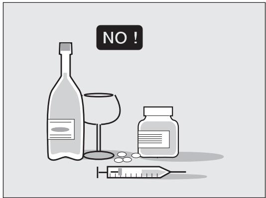
The use of medicines, alcohol and drugs or psychotropic substances notably increases the risk of accidents. Be sure that you are in good psychophysical conditions and fit for driving and pay particular attention to physical weariness and drowsiness.
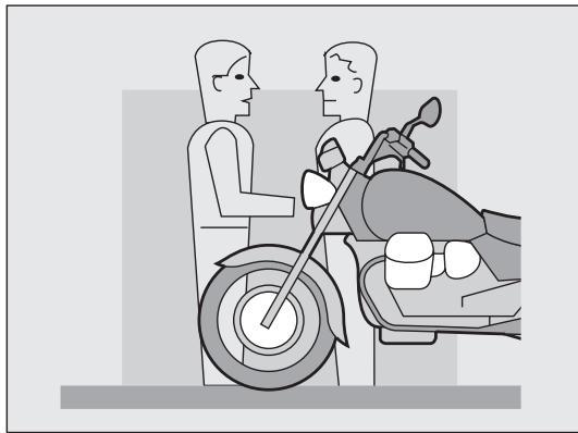
Most road accidents are caused by the driver's lack of experience.
NEVER lend the vehicle to beginners and, in any case, make sure that the driver has all the requirements for driving.
Rigorously observe all road signs and national and local road regulations.
Avoid abrupt movements that can be dangerous for yourself and other people (for example: rearing up on the back wheel, speeding, etc.), and give due consideration to the road surface, visibility and other driving conditions.
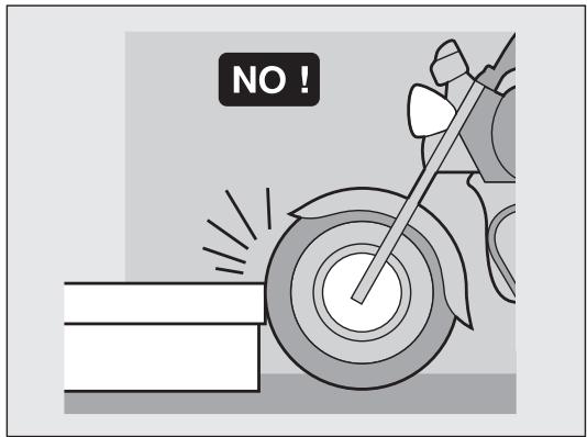
Avoid obstacles that could damage the vehicle or make you lose control.
Avoid riding in the slipstream created by preceding vehicles in order to increase your speed.


STOP150m

1

Always drive with both hands on the handlebars and both feet on the rider's footboards, in the correct driving posture.
Avoid standing up or stretching your limbs while driving.
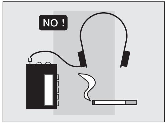
The driver should pay attention and avoid distractions caused by people, things and movements (never smoke, eat, drink, read, etc.) while driving.
Use only the vehicle's specific fuels and lubricants indicated in the table "REFUELINGS"; check all oil and fuel.
If the vehicle has been involved in an accident, make sure that no damage has occurred to the control levers, pipes, wires, braking system and vital parts.
If necessary, have the vehicle inspected by an MOTO
GUZZI Official Dealer who should carefully check the frame, handlebars, suspensions, safety parts and all the devices that you cannot check by yourself.
Always remember to report any malfunction to the technicians to help them in their work.
Never use the vehicle when the amount of damage it has suffered endangers your safety.
Never change the position, inclination or colour of: number plate, direction indicators, lights and horns. Any modification of the vehicle will result in the invalidity of the guarantee.
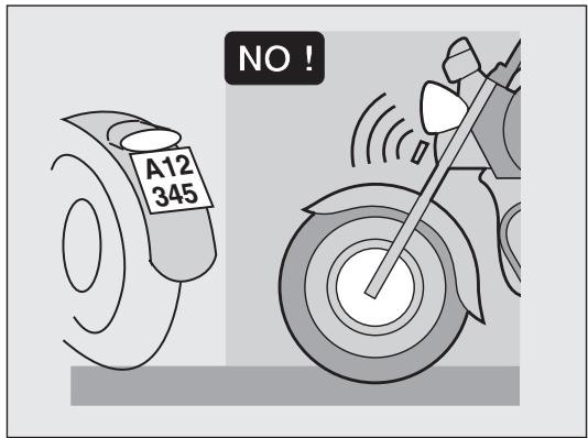
Any modification of the vehicle and/or the removal of original components can compromise vehicle performance levels and safety or even make it illegal.
We recommend respecting all regulations and national and local provisions regarding the equipment of the vehicle.
In particular, avoid all modifications that increase the vehicle's performance levels or alter its original characteristics.
Never race with other vehicles.
Avoid off-road driving.
Before starting, always wear a correctly fastened crash helmet. Make sure that it is homologated, in good shape, of the right size and that the visor is clean.
Wear protective clothing, preferably in light and/or reflecting colours. In this way you will make yourself more visible to the other drivers, thus notably reducing the risk of being knocked down, and you will be more protected in case of fall.
This clothing should be very tight-fitting and fastened at the wrists and ankles; strings, belts and ties should not be hanging loose; prevent these and other objects from interfering with driving by getting entangled with moving parts or driving mechanisms.
Vetements
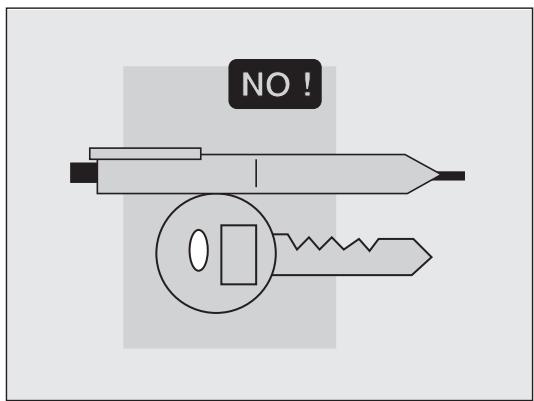
Do not keep objects that can be dangerous in case of fall, for example pointed objects like keys, pens, glass vials etc. in your pockets (the same recommendations also apply to passengers).
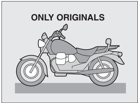
The owner of the vehicle is responsible for the choice, installation and use of any accessory.
Avoid installing accessories that cover horns or lights or that could impair their functions, limit the suspension stroke and the steering angle, hamper the operation of the controls and reduce the distance from the ground and the angle of inclination in turns.
Avoid using accessories that hamper access to the controls, since this can prolong reaction times during an emergency.
Big fairings and windshields installed on the vehicle may produce aerodynamic forces that affect the stability of the vehicle, especially when riding at high speed.
Accessoires
Make sure that the equipment is well fastened to the vehicle and not dangerous during driving.
Do not install electrical devices and do not modify those already existing to avoid electrical overloads, because the vehicle could suddenly stop or there could be a dangerous current shortage in the horn and in the lights.
MOTO GUZZI recommends the use of genuine accessories.
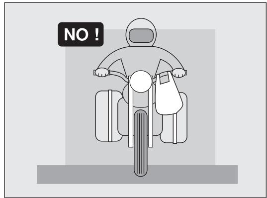
Be careful and moderate when loading your luggage. Keep any luggage loaded as close as possible to the center of gravity of the vehicle and distribute the load uniformly on both sides, in order to reduce umbalance to the minimum. Furthermore, make sure that the load is firmly secured to the vehicle, especially during long trips. Avoid hanging bulky, heavy and/or dangerous objects on the handlebars, mudguards and forks, because the vehicle might respond more slowly in turns and its manoeuvrability could be unavoidably impaired. Do not place bags that are too bulky on the vehicle sides and do not ride with the crash helmet, because they could hit people or obstacles, making you lose control of the vehicle.
Chargement
Do not carry any bag if it is not tightly secured to the vehicle.
Do not carry bags which protrude too much from the luggage-rack or which cover the lights, horn or indicators.
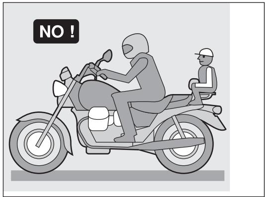
Do not carry animals or children on the luggage rack.
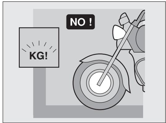
Do not exceed the maximum load allowed for each sidebag.
When the vehicle is overloaded, its stability and its manoeuvrability can be compromised.
-
Interna (long life) NGK PMR8B
-
Esterna. NGK BPR6ES
4-stroke, twin cylinder
Cylinder configuration 90° V-twin
Bore: 92 mm
Stroke: 80 mm
Capacity: 1064 cc
Compression ratio: 9.8:1
Cooling: air
Timing system
With 2 valves per head controlled by light alloy rods and rocker arms driven by tappets.
Feed system
Multipoint electronic injection, timed sequential MAGNETI MARELLI IAW, Alpha-n system, 2 throttle valves Ø 40 mm with Weber IW031 injectors, electric pump with pressure regulator, digital control of optimised injection times.
Exhaust system
In stainless steel - 2 pipes connected to an expansion chamber, connected to two chromed steel silencers; three-way catalytic converter with Lambda sensor.
Lubrication
Pressure fed by gear pump
Wire mesh and cartridge filters on oil sump
Normal lubrication pressure set by pressure valve on oil sump.
Low oil pressure sensor (electrical) on crankcase.
Generator / Alternator
On front of crankshaft. Output power: 350W at 5000 rev./min. (14V - 25A).
Ignition
"MAGNETI MARELLI IAW 15 RC" Inductive discharge digital electronics. Spark plugs: Inner (long life) .NGK PMR8B Outer .NGK BPR6ES Spark plug gap: .0.6-0.7 mm Ignition coils .2, mounted on frame.
Starter
Electric starter motor with electromagnetic ratchet control. Ring gear on the flywheel. START «j» pushbutton on right handlebar.
Transmission
Clutch
Twin-plate dry clutch with control lever on handlebar (left-hand side).
Primary drive
With helical gears, 1:1.2353 (Z=17/21).
Gearbox
5-speed, front engaging, constant mesh.
Incorporated Cush drive
Control pedal on left side of machine.
Gear ratios:
1st 1:2 (Z=14/28)
2nd 1:1.3889 (Z=18/25)
3rd 1:1.0476 (Z=21/22)
4th 1:0.8696 (Z=23/20)
5th 1:0.7500 (Z=28/21)
Final drive
Cardan shaft with gears
Overall gear ratios (engine-wheel)
1st gear = 1:10,1912
2nd gear = 1: 7,0772
3rd gear = 1 :5,3382
4th gear = 1: 4,4309
5th gear = 1 :3,8217
Frame
High tensile stress modular duplex tubular cradle.
Suspension
Front:
MARZOCCHI telescopic hydraulic fork
"045 mm" whose rebound and compression can be adjusted separately.
Rear:
Swinging arm with two adjustable hydraulic shock absorbers for rebound hydraulic damping.
Wheels
Spoke wheels with tubeless rims in the dimensions:
Front
18"x2.50-MT-DOTE
Rear
17^ × 4.00 -MT-DOTE
Tires
Front
110/90 - 18 - 61V
Rear
150/70 - 17 - 69V
Brakes
RH front brake
Stainless steel semi-floating with differentiated 4 piston calipers, fixed type. Lever control positioned on the RH side of the handlebar.
Hydraulic transmission independent from rear brake; disk = 320mm
braking cylinder = 30 / 34~mm
master cylinder = 13~mm
LH front and rear brakes
Integral braking system with brake-power limiter and metering valve.
Stainless steel semi-floating with differentiated 4 piston calipers, fixed type.
Fixed disk with 2-piston floating calliper. Pedal lever control in the centre on the RH side of the vehicle.
front disk = 320~mm
rear disk = 282~mm
braking cylinder = 30 / 32 ~mm
master cylinder = 16~mm
Rear brake is connected to front left brake through hydraulic transmission. Each single components of the front left brake has the same dimensions of those in the manual front right brake.
Dimensions and weight
Wheelbase (loaded) mm 1560
Maximum length mm 2380
Maximum width mm 815
Minimum ground clearance mm 165
Maximum height (without windscreen) ...mm 1150
Maximum height (Touring) mm 1470
Rider's seat height mm 770
Weight (unloaded) kg 251

The motorcycle equipped with windscreen, bags and foot guards ensure higher riding port but limit vehicle aerodynamic features.
For this reason, it is recommended the max. riding speed of 130km / h be never exceeded, especially when riding under max. load conditions.
REFUELINGS
| Part | Litres | Recommended product |
| Fuel tank (reserve approx 4 lt.) | approx. 19 | Only use unleaded petrol (95 NO-RM/min. and 85 MON) |
| Oil sump | 3 | Olio "Agip 4T RACING SAE 10W/60" |
| Gearbox | 0.750 | Olio "Agip Rotra MP SAE 80 W/90" |
| Transmission box (bevel gears lubrication) | 0.250 | "Agip Rotra MP SAE 80 W/90" |
| Telescopic front fork adjustable (per leg) | 0.485 | Shock - Absorbers oil (SAE 10) |
| Front and rear brake circuits | - | "Agip Brake Fluid - DOT4" |
52 CHARACTERISTIQUES GENERALES
Moteur
-
intern (long life) .....NGK PMR8B
-
extern . NGK BPR 6 ES
- Gang = 1:2 (Z = 14/28)
- Gang = 1:1,3889 (Z = 18/25)
- Gang = 1:1,0476 (Z = 21/22)
- Gang = 1:0,8696 (Z = 23/20)
- Gang = 1:0,7500 (Z = 28/21)
Sekundärtrieb
- Gang = 1:10,1912
- Gang = 1: 7,0772
- Gang = 1: 5,3382
- Gang = 1: 4,4309
- Gang = 1: 3,8217
Rahmen
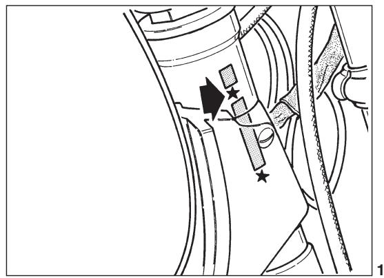
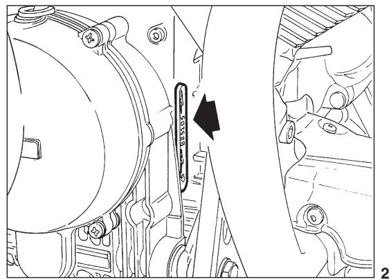
FRAME AND ENGINE NUMBERS (fig. 1-2)
The frame number is stamped on the downtube; this number is entered in the motorcycle's log-book and is thus used to identify the vehicke for legal purposes. The engine number is stamped on the crankcase.
NUMEROS D'IDENTIFICATION (fig. 1-2)
Always use approved «MOTO GUZZI Original Spares» only when replacing or repairing parts. Use of spares which are not approved will invalidate warranty rights.
Pieces détachées
1 Key switch for devices and steering lock.
Position OFF «» vehicle stationary. Key removable (no contact).
Position ON «» vehicle ready to be started. All circuits are on. Key not removable.
Position LOCK «O» steering locked. Engine off, no contact, key removable.
Position P «P» steering locked. Engine off the parking light is on. Key removable.
APPAREILS DE CONTROLE ET COMMANDE
In order to use the steering lock mechanism, proceed as follows:
Turn the handlebars to the left.
Press the key downwards and release it, then turn it in an anticlockwise direction to the LOCK or P « position.
WARNING: Never turn the key to position LOCK «» or P «» when the engine is running.
2 Odometer, tachometer.
3 Rev counter.
4 Pilot light (green) «Neutral». Lights up when the gearbox is in neutral.
5 Pilot light (green) for flashing right indicators.
6 Petrol tank reserve pilot light (orange).
7 Pilot light (green) for flashing left indicators.
8 Oil pressure pilot light (red). Goes out when the oil pressure is sufficient to ensure engine lubrication.
9 Pilot light (blue) for main beam.
10 Partial rev counter zeroing.
If the vehicles are equipped with this device, lights will automatically turn on when the automatic light Key-operated switch is positioned to «Q».
For this reason, standard light switch is not fitted.
Position the automatic light switch to «» to turn the lights off.
Before starting the vehicle, ensure that light dip switch is positioned to (headlight to low beam).
These are mounted on the left handlebar.
Switch «A» (fig. 4)
Position «D» dipped beam.
Position «D» main beam.
Position flashing light control.
Horn button, passing and direction indicators (fig. 4)
These are mounted on the left handlebar:
Push-button B (▶) sounds the electric horn when pressed.
Push-button C:
position for right turn signals control.
position « 念 for left turn signals control.
press the switch to disconnect flashers.
Starter button and engine stop switch
(fig. 5)
These are mounted on the right handlebar.
With the key «1» in fig. 3 position ON «♀», the vehicle is ready for starting. To start the engine:
check that switch «B» is in position (run);
■ pull the clutch lever in to disengage the clutch fully;
■ if the engine is cold, put the «CHOKE» control «D» in the starting position «1» (see fig. 4);
press the starter button «C» «(i)» (start).
To stop the engine in case of emergency:
turn the switch to position (off).
Once the engine has stopped, turn the key switch (fig. 3) anti-clockwise until OFF «»; remove the key from the switch.

Before start, put switch «B» in (RUN) position.
It is located on handlebar right-hand side; Switch «A»
Position «·» handgrip heating not activated;
Position «» minimum heating;
Position «» maximum heating.
Throttle twist grip («D» in fig. 5)
The throttle control is on the right handlebar; turning the twist-grip towards the rider opens the throttle, turning it away from the rider closes it.
Clutch lever («E» in fig. 4)
This is on the left handlebar and is only to be used when starting or changing gear.
Brake lever, r/h front brake
(«E» in fig. 5)
This is on the right handlebar and controls the master cylinder of the right front brake.
The «CHOKE» is on the left handlebar and is used for cold starts.
Position «1» CHOKE on; starting position.
Position «2» CHOKE off; engine running.
Brake pedal for left front brake and rear brake («A» in fig. 16)
This is centrally located on the right side of the vehicle and is linked to the master cylinder by a tierod; this pedal operates the front left and rear brakes together.
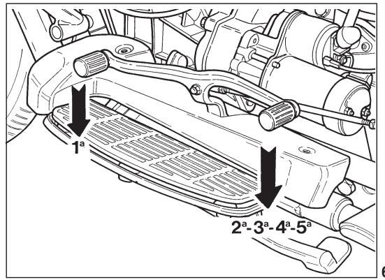
This is a double rocker arm type, situated on the left of the motorcycle:
1st gear: push front pedal down;
2nd, 3rd, 4th, 5th gears: push rear pedal down;
neutral: between 1st and 2nd gears.

WARNING! Before changing gear disengage the clutch fully.
6
To open, turn the key anti-clockwise.

WARNING! Fuel used in explosion engines is highly inflammable and can explode under certain conditions.
Always refuel and service the vehicle in a well ventilated area when the engine is stopped.
Do not smoke when refuelling and when in an area subject to fuel vapours.
Avoid contact with naked flame, sparks and any sources which may cause fire or explosion.
Avoid overfilling as fuel might fire up when in contact with hot engine parts.
If fuel is accidentally spilt, ensure that involved area is completely dry before starting the vehicle.
Do not fill the fuel tank up to the edge as fuel expands under heat and direct sun light.
Carefully plug the fuel tank after refuelling.
Avoid any contact with the fuel.
Do not inhale fuel vapours.
Do not swallow any fuel and do not take the fuel from a container using a hose.
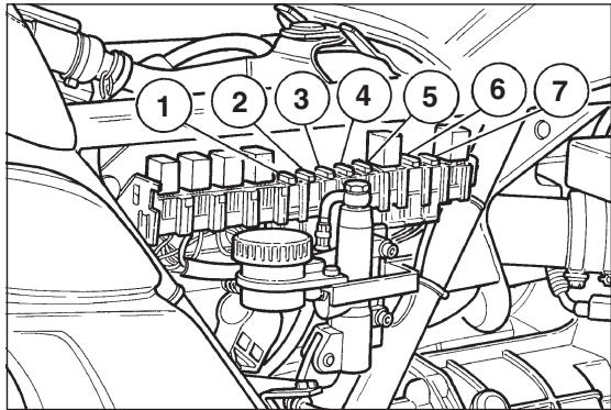
This is located on the right side. To enter it is necessary to remove the side cover and possibly the front saddle.
The terminal board has 7 fuses.
Before changing a burnt fuse, trace and repair the cause of the trouble.
Fuse «1»: battery recharge (30A).
Fuse «2»: key switch (15A).
Fuse «3»: driving beam, traffic beam, horn (15A).
Fuse «4»: direction indicators, parking lights (5A).
Fuse «5»: 12V-Power outlet (15A).
Fuse «6»: ECU (5A).
Fuse «7»: Pump, coils, injectors (10A).
| F1 = 30A | F2 = 15A | F3 = 20A | F4 = 5A | F5 = 15A | F6 = 5A | F7 = 10A |
| RICARIA BATTERIA | COMMUTATORE A CHIAVE | L.ABB / ANAB AVV. ACUST. | INDIC. DIREZ. L. POSIZONIE | PRESA 12V | ECU | POMPA BOBINE INETTORI |
| BATTERY RECHARGER | KEY SWITCH | L. HB / LB HORN | DIREC. INDIC. DIPPED L. | SOCKET 12V | ECU | PUMP COIL INJECTORS |
WARNING! Do not repair faulty fuses. Never use fuses other than those specified. The electric system might damage or even a fire might break out if a short circuit occurs.
A short circuit or overload might lead to frequent fuse damage. If so, contact a MOTO GUZZI dealer.
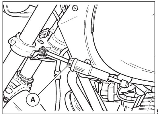
It is fitted between the frame and steering joke on the left hand side.
To harden or loosen the steering, turn in or out the knob «A».
It adds to steering accuracy and stability for improved handling under any conditions.
Side bags and top-case
(CALIFORNIA TOURING) (fig. 10)
To release the sidebags and the top-case from the supports, pull lever «A» of the clamping device after having released the lock using its key. To open the lids, lift lock «B» after having released it with its key.

N.B. - The maximum load for each side bag is 5kg ; loads should be equally distributed between the two bags.
The maximum load allowed for the top-case is 5 kgs.
Sacoches laterales et top-case (uniquement CALIFORNIA TOURING) (fig. 10)
The driver's saddle is clamped by device «A» operated by means of a flexible transmission by the «B» lever, inserted in the helmet carrier device «C». To unclamp the saddle it is necessary to pull lever «B» downward after having released it by turning helmet carrier lock «C». To clamp the saddle, it must be placed in its seat on the frame, pressed on, then lock lever «B». The passenger's seat is fixed in place.
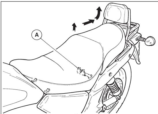
The helmet can be left with the motorcycle, using the helmet holder with lock «C».
N.B. - never leave the helmet in the holder when the motorcycle is running, as it may interfere with the moving parts.
Documents and objects holder
(A) in fig. 12
To gain access remove the driver's seat (see Fig. 11).
Dispositif porte-casque (fig.11)
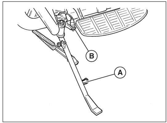
The motorcycle is fitted with a side stand for parking. When the side stand is in use (i.e. in the out position) it activates a microswitch «B» controlling a relay which disenables to the starter motor; it is therefore not possible to start the vehicle with the side stand in use.
12V power outlet («A» in fig. 14)
It is at the centre, on the left-hand side, it is useful for small 12 Volt electric items with max. power of 180W.
A WARNING!
Use the power outlet when bike is stopped
only.
CAUTION Do not le
and ON for too long or the battery will run flat.
Prise de courant 12V («A» in fig. 14)
that there is sufficient fuel in the tank;
that the engine oil is on the right level;
■ the ignition key is in position ON «Q» (see fig. 3);
Proper operation of acoustic and visual devices;
that the following warning lights are on:
- red warning lights: oil pressure;
— green warning light: «NEUTRAL» indicator;
that the «CHOKE» control lever is in the starting position (if the engine is cold) («1», fig. 4);
that switch B (fig. 5) is in position (run).
Once the engine has started, and before putting the «CHOKE» lever back to its normal running position («2» in fig. 4), allow the engine to idle for a few seconds in summer or a few minutes in winter.
UTILISATION DU MOTOCYCLE
ATTENTION! - If the «green» warning light does not come on when the ignition switch is on (see ON «♀» in fig. 3) this means that a gear is engaged; starting the vehicle in this condition could be dangerous.
Before starting, always check that the engine is in «neutral».
Warm start
Follow the same procedure as that for the cold start but without the «CHOKE» control in the start position («1», fig. 4).
WARNING! - The starter motor should not be operated for more than 5 seconds; if the engine doesn't start, wait for 10 seconds before the following starting operation. Anyway act on the starter button C () in fig. 5 only with the engine completely stopped.
On the way
To change gear, shut the throttle, disengage the clutch fully and engage the next gear; then engage the clutch gradually while opening the throttle.
The gear change pedal should be operated firmly and surely.
When changing down use the brakes gradually and close the throttle gradually to avoid over-reving the engine, when releasing the clutch lever.
Stopping the motorcycle
Close the throttle and use the brakes; just as the vehicle is about to stop disengage the clutch. These three operations should be carefully coordinated to maintain full control of the vehicle.
When slowing down in normal conditions, use the gearbox to provide engine braking to slow the vehicle; take care not to over-reving the engine. Use the brakes (especially the front brake) with particular care when roads are slippery or wet.
To stop the engine, turn the ignition switch till the position OFF «» (see fig. 3).

N.B. Avoid sharp braking, sudden slowing-down and limit braking as far as possible.
Arrêt
On badly lit roads, leave the parking lights on.
Turn the key switch to position P «P» (see fig) and remove the key from the switch.
IMPORTANT
Never leave parking lights on for long periods or the battery will run down.
WARNING
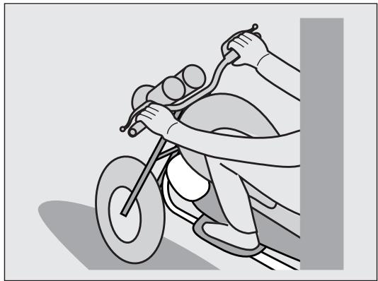
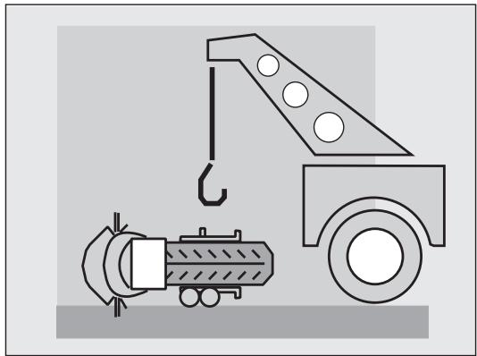
Park the vehicle onto a steady flat surface so that the motorcycle cannot fall onto the ground.
Do not lean the vehicle against walls or lay it down onto the ground. Ensure that the vehicle, especially its hot parts, cannot cause injuries to people and children. Do not park close to inflammable material, such as wood, dry leaves and son on, if the engine and the exhaust system are hot. Do not leave the vehicle unguarded if the engine is running or the ignition key is into the ignition switch.
Do not seat on the motorcycle if the stand is down.
Stationnement
The recommendations below should be followed when running-in:
Before riding, run the engine at low revs until it has warmed up.
- Do not exceed the rpm shown in the table; it is also advisable to run the engine at varying speeds rather than at a constant speed.
Before stopping reduce the speed gradually to avoid subjecting components to sudden changes in temperature.
Ride carefully for the first 100km (62 miles) to allow proper bedding of brake pads. Avoid sudden braking.
Remember that components need several thousand kilometers before they are properly bedded in; care taken in this period will ensure prolonged vehicle life.
A 10MOUNTANT
After the first 310/1000 mi (500/1500 km) have the motorcycle controlled by an authorized MOTO GUZZI dealer as specified under «1000 mi (1500 km)» in «MAINTENANCE SCHEDULE» on page 145 so to avoid injuries to rider/other people and damages to the vehicle.
Should the oil level drop to the minimum level before the first 500÷ 1500 kilometers have been completed then carry out a complete oil change rather than just topping up. Recommended oil: «Agip RACING 4T SAE 10W-60».
BREAKING-IN RPM
| Kilometers | Max. RPM |
| From 0 to 1000 | 5000 |
| From 1000 to 2000 | 6000 |
| From 2000 to 4000 | Gradually increase rpm until maximum permissible level is reached. |
110 RODAGE
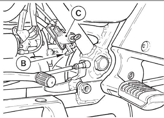
Adjusting the clutch lever (fig. 15)
There should be 3 ÷ 4 mm of free play at the lever; turn the adjuster screw «A» to obtain the desired play. Play can also be adjusted on the cable adjuster «B» located on the right side of the gearbox. First loosen the lock nut «C» and then adjust.
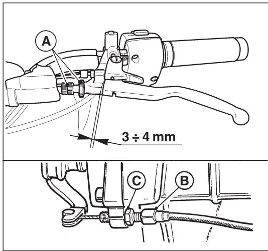
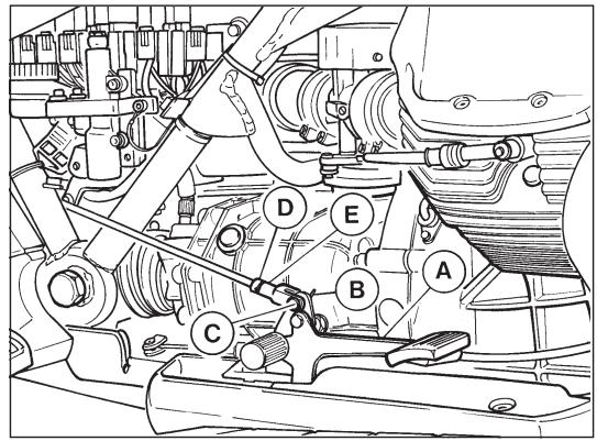
Adjusting the brake pedal of rear and left-hand front brakes (fig. 16)
To vary the position of the control pedal «A», do the following:
remove the split pin «B», pull out the pin «C», loosen the counter-nut «D» and tighten or back off the fork «E» until obtaining the desired position of the control pedal;
■ replace the pin «C» with the relative split pin «B».
Checking brake pads wear
Check the thickness of the brake pads every 3000 km:
Wear limit 1.5mm
If the pads are below the wear limit they should be changed.
There is no need to bleed the brakes when the new pads have just been fitted; pumping the brake lever a few times will return the caliper pistons to their normal position.
When changing the pads, also check the flexible hoses; if damaged they should be replaced immediately.

N.B. - Use the brakes with moderation for the first 100km (62 mi) after fitting new pads, to allow the pads to get properly used in.
Checking brake disks
The brake disks must be perfectly clean, with no oil, grease or other dirt on them. They should also show no signs of scoring.
The torque wrench setting of the screws that fix the disk to the hubs is 3 ÷ 3,2 kgm.

IMPORTANT! - Do not change the braking system components and the rear
suspension assay. These components must be replaced with original spare parts only and the operation must be done by authorized technicians only.
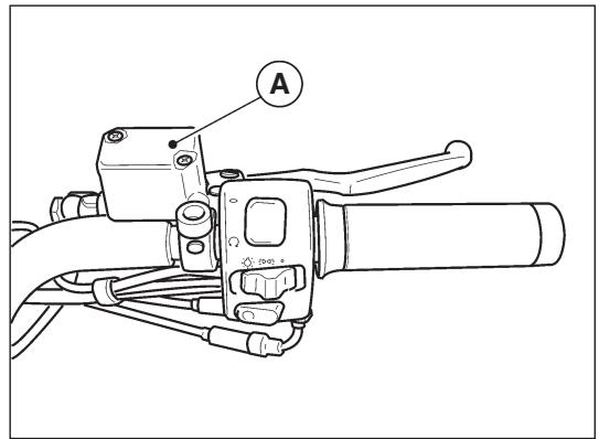
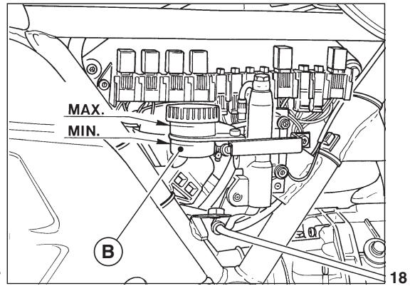
Checking the brake fluid in the master cylinder reservoir (figs. 17 and 18)
To ensure efficient operation of the brakes:
1 Make frequent checks of the fluid level in the front «A» in fig. 17 and rear «B» in fig. 18 reservoirs.
The level should always be above the minimum mark on the reservoirs.
2 Top up the brake fluid when necessary or at regular intervals. Only use recommended brake fluid in sealed containers for topping up.
Fluid containers should only be unsealed immediately before they are about to be used.
3 The fluid in the brake reservoirs should be changed completely after about every 20,000km or at least once a year.
To ensure efficient braking there should be no air bubbles in the brake circuit; if the brake lever has too much travel or a spongy action, this means that there are bubbles in the brake circuit.
Never use mineral oils or greases for lubricating parts. If no suitable lubricant is available, we recommend the light greasing of the rubber and metal parts with brake fluid.
Recommended fluid «Agip Brake Fluid DOT 4».
WARNING Wear latex gloves when servicing the hydraulic circuit.
Brake fluid may cause skin irritations. Avoid contact with the eyes.
17
Wash with abundant water in case of skin contact. Call an eye specialist or a doctor in case of fluid contact with the eyes.
DISPOSE OF THE FLUID IN COMPLIANCE WITH CURRENT LAWS.
KEEP AWAY FROM CHILDREN.

IMPORTANT. Fluid should be handled with care, as it may dissolve paintwork.

These operations are best carried out by an authorized dealer.
Adjustable telescopic fork adjustment
(fig. 19)
The motorcycle is equipped with a hydraulic telescopic fork with separate adjustment of shock-absorbers during rebound and compression.
Hydraulic damping can be adjusted by using the setting handles «A» and «B».
The left setting handle «A» adjusts the hydraulic damping during rebound; the right setting handle «E» controls damping during compression.
Both setting handles have 15 adjustment positions (notches); turning them clockwise (+) increases damping and decreases it in the opposite direction (-).

N. B.: Do not force the setting handles beyond the limit positions.
Rear shock-absorber adjustment
(fig. 20)
The motorcycle is equipped with shock-absorbers with adjustment of hydraulic damping during rebound.
To adjust hydraulic braking in extension, work on the ring nut «A».
Turn it counter-clockwise (→HARD) to increase, clockwise (←SOFT) to decrease.
N.B.: To ensure good motorcycle stability, it is recommended to make sure that both shock-absorbers are adjusted to the same position.
IMPORTANT - do not change the braking system components and the rear suspension assy. These components must be replaced with original spare parts only and the operation must be done by authorized technicians only.
Remove the wheel as follows:
place the machine securely on its centre stand, place a support under the engine base in order to lift the wheel from the ground;
undo the bolts «A» holding the brake calipers to the fork legs and remove the calipers complete with hoses;
■ loosen the pinch bolts «B»;
■ unscrew and remove the wheel spindle «C» paying attention to the position of the spacer «D», then remove the wheel;
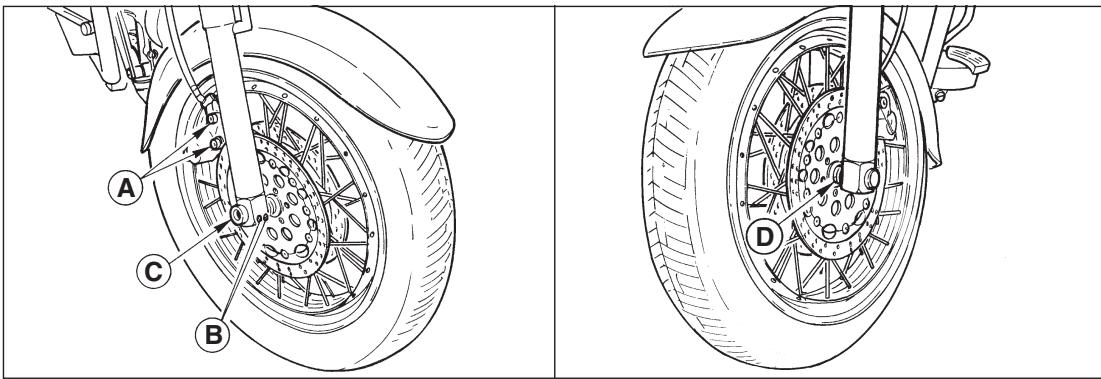
DEMONTAGE DES ROUES DU VEHICULE
Roue AV (fig. 21)
refitting the wheel is the reverse of the above procedure; care should be taken to fit the spacer in the correct position; pump the brake lever and pedal a few times to return the caliper pistons to their normal position.
■ unscrew and slide out the wheel spindle «C» paying attention to the position of the spacers «D», then remove the wheel;
refitting the wheel is the reverse of the above procedure; care should be taken to fit the spacers in the correct position; pull the brake lever several times to return the caliper piston to its normal position.
WARNING FOR WHEELS WITH SPIKES
At each maintenance control, check for integrity and tension of the wheel spokes. A wrong spoke tension or the breakage of one or more spokes may affect the wheel, thus compromising the vehicle safety and stability. Always respect the maximum tolerated load specifications.
The non observance of the requirements for tyres pressure or load limits can affect the handling, operation and control of the motorcycle. The max. allowed weight supported by this motorcycle is 200 kgs (passengers
- luggage + accessories).
Divided up as follows:
- Front axle 52 kg.
Rear axle 148 kg.
ATTENTION POUR LES ROUES AVECBRAS
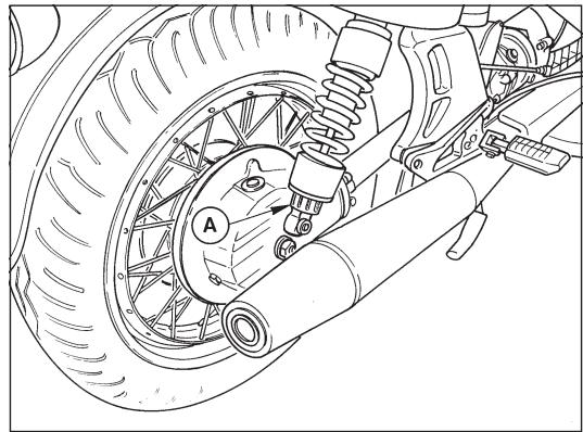
To disassemble the rear wheel from the fork arm and gearbox, do the following:
place the vehicle on the middle kick-stand;
remove the left muffler;
disassemble the brake calliper «C» from the calliper plate «B»;
■ unscrew the nut «D» with washer «E» on the housing side pin
■ loosen the pin lock screw «F» on the fork arm;
remove the pin «G» from the housing, from the hub and from the fork arm;
remove the calliper plate «B»
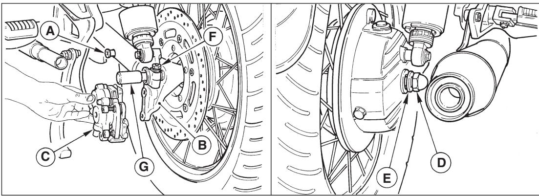
■ tilt the vehicle on the right side enough to be able to pull the wheel off the fork, arm and transmission housing. To replace the wheel, reverse the disassembly order remembering to insert the calliper plate on the stop «A» of the left arm of the swinging fork.
Tyres are among those machine components which require regular checking.
Machine stability, rider comfort and safety all depend on good tyre condition.
Do not use tyres with less than 2mm of tread. Incorrect tyre pressures can cause instability and excessive tyre wear.
Tyre pressures:
■ front wheel: with one or two riders 2.3 BAR.
■ rear wheel: with one rider 2.5 BAR; with two riders 2.9 BAR.
The values indicated refer to normal use (tourism). For use at continuous maximum speed, on the motorway, it is recommended to increase the pressure in the front wheel by 0.2 BAR.
IMPORTANT! If a tyre needs
If a tyre needs replacing, use the same make and type as the first-equipment tyre. Tyre pressure should be measured when tyres are cold.
Pneus
The motorbike is equipped with light-alloy rims which, despite featuring a high mechanical resistance, can however get damaged, both from an aesthetic and functional point of view, by using unsuitable tools during removal and refitting of the wheel onto the rim.
For the above procedures, it is therefore advisable to use iron tools which do not have grooves and sharp edges on the parts which come into contact with the edge of the rim.
The contact surface must be wide, well smoothed and with suitably rounded edges; using one of the special, commercially available lubricants will help the tire slide into and bed-in on the rim during disassembly and reassembly, and it will eliminate the need to heavily load the iron tools; for this reason, it is also very important that the tires' bead heels are well set in the rim's central channel.
Observe the rotation direction indicated by the arrow on the tire side when assembling the tires.
| MILEAGECOVERED ITEMS | 1000 mi. (1500 km) | 6000 mi. (10000 km) | 12000 mi. (20000 km) | 18000 mi. (30000 km) | 24000 mi. (40000 km) | 30000 mi. (50000 km) |
| Engine oil | R | R | R | R | R | R |
| Oil filter cartridge | R | R | R | R | R | R |
| Wire gauze oil filter | C | C | C | C | C | C |
| Air filter | R | R | R | R | R | |
| Outer spark plugs | A | R | R | R | R | R |
| Inner spark plugs | R | |||||
| Carburetion | A | A | A | A | A | A |
| Nuts and bolts | A | A | A | A | A | A |
| Fuel tank, pipes | A | A | A | |||
| Gearbox oil | R | R | R | R | R | R |
| Rear drive box oil | R | R | R | R | R | R |
| Wheel and steering bearings | A | A | ||||
| Fork legs oil | R | R | R | |||
| Starter motor and generator | A | A | ||||
| Brake systems fluid | A | A | R | A | R | A |
| Brake pads | A | A | A | A | A | A |
| Tightening of cylinder head nuts | A |
KEY: A = Inspections - Adjustments - Possible replacements - Servicing. / C = Cleanings. / R = Replacements.
Occasionally, lubricate joints and cables; every 1000km (600 miles) check the engine oil level.
In any case, replace the motor oil, the oil filter and the brake fluid, oil at least once a year.
Periodically check the tension of the wheel spokes.
146 PROGRAMME D'ENTRETIEN
Preparations for washing
Before washing the vehicle, the following parts should be covered with a waterproof material: the rear part of the silencers, the clutch and brake levers and pedals, the throttle twist-grip, the left-hand light switch, the ignition key switch, the shaft with driving couplings.
Washing
Avoid spraying water too much pressure on the instruments and the front and rear hubs.
Drying
Remove the protective coverings.
Thoroughly dry the vehicle.
Test the brakes before using the vehicle.
N.B. - To clean the painted parts of the engine unit (engine, gearbox, transmission box, etc.) the following products may be used: diesel oil, petrol or water-based neutral detergents for car cleaning.
These products should be washed off immediately with water; do not use water at high temperatures or pressures.
NETTOYAGE - LONGUE INACTIVITE
Nettoyage
If the vehicle is to remain idle for a considerable period of time (e.g. for the winter period) it should be stored in the following way:
clean the vehicle thoroughly;
- empty the fuel tank and feeding system. If left for a long time, the fuel will evaporate leaving incrustation and residue;
remove the outer spark plugs and put a few drops of SAE 30 oil into the cylinder. Turn the crankshaft for a few revolutions and then replace the spark plugs;
reduce the tyre pressures by 20% ;
position the vehicle so that its wheels are not touching the ground;
smear a layer of oil on unpainted parts to prevent rust;
remove the battery and store in a dry place away from the direct sunlight and where there is not danger of frost; check the battery charge once a month;
cover the vehicle but in such a way that the air can circulate.
Longue inactivité
CLEANING THE WINDSCREEN
The windscreen can be cleaned using most of the soaps, cleaners, waxes and polishes commercially available for glass and plastic.
The following precautions should be taken:
do not wash or polish the windscreen in direct or strong sunlight or when temperatures are high;
■ under no circumstances use solvents, lyes or similar products;
■ do not use abrasive substances, pumice, sand/ emery paper, files, etc.;
■ wash all dust and dirt away before polishing. Small superficial scratches can be removed using a mild polish;
paint or sealing compound can be removed before harden by using diesel, isopropylic alcohol or butyl cellosolvent (do not use methyl alcohol);
- use soft cloths, sponges,chyam leathers or cotton wool; do not rub too hard. Do not use paper towels or man-made fibre cloths as they tend to scratch the windscreen.
Deep scratches cannot be removed by hard rubbing or the use of solvents.
NETTOYAGE DU PARE-BRISE
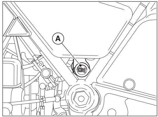
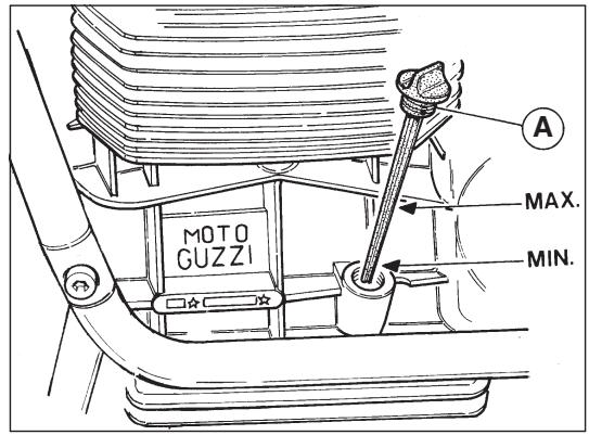
Checking the oil level (fig. 23)
Check the crankcase oil level every 1000 km; the oil should reach the «Max» mark on the dipstick «A». If the oil is below this level, top up with the recommended type and grade of oil.

N.B. - The oil level check should be carried out after the engine has run for a few minutes:
the dipstick plug «A» should be introduced in the oil opening without screwing it.
LUBRIFICATION
Oil change (figs. 23 & 24)
The oil should be changed after the first 500 ÷ 1500 km and every 10000 km thereafter. Change the oil when the engine is warm.
Allow the sump to drain fully before filling with new oil.
«A» Oil filler plug with dipstick (fig. 23);
"B" Oil drain plug (fig. 24).
Oil required: 3 litres of «Agip 4T RACING SAE 10W/60».
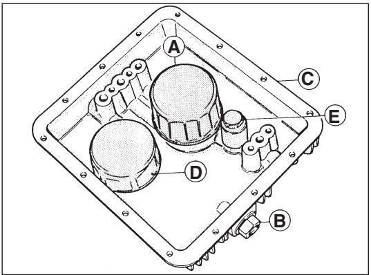
Changing the filter cartridge and cleaning the mesh filter (fig. 24)
After the first 500 ÷ 1500 km (first oil change) and afterward every 10,000 km, replace the filtering cartridge «A» by doing the following:
■ unscrew the drain plug «B» and allow the sump oil to drain off fully;
undo the screws and remove the sump cover «C» from the crankcase: this assembly includes the filter cartridge «A», the mesh filter «D» and the oil pressure valve «E».
■ When changing the filter cartridge «A» it is also a good idea to remove the mesh filter «D» and wash it in petrol; dry by blowing with compressed air. Blow the oil ducts in the sump out with compressed air and refit the mesh filter.
Do not forget to fit a new sump gasket when refitting the sump.
It is recommended to perform the operation described above at our dealer locations.
Checking the oil level (fig. 25)
Check the oil level every 5000km ; the oil should just reach the level plug hole «B».
If the oil is below this level top up with the recommended grade and type of oil.
Oil change
The gearbox oil should be changed after the first 500-1500 Km and then every 10.000Km . Drain the oil when the gearbox is warm as the oil is more fluid and drains more easily.
Allow the gearbox to drain fully before filling with new oil.
«A»Filler plug.
Oir required: 0.750 litres of Agip Rotra MP SAE 80W/90.
Rear transmission box lubrication
(fig. 26)
Checking the oil level
Check the oil level every 5000km ; the oil should just reach the level plug hole «A».
If the oil is below this level top up with the recommended grade and type of oil.
Oil change
The transmission box oil should be changed after the first 500-1500 Km and then every 10.000 Km.
«B» Bouchon de niveau.
«C» Bouchon de vidange.
Drain the oil when the box is warm as the oil is more fluid and drains more easily.
Allow the box to drain fully before filling with new oil.
«A» Level plug.
«B»Filler plug.
C Drain plug
Oil required: 0.250 litres of «Agip Rotra MP SAE 80W/90» oil.
Cambio olio forcella anteriore
Front fork oil change
After the first 500 ÷ 1500 Km and afterwards every 20.000 km or at least once a year.
See table «REFUELINGS» on page 51 for recommended oil type and quantity.

These operations are best carried out by an authorized dealer.
Greasing
To grease:
■ steering bearings;
■ swinging arm bearings;
control rod joints;
side stand fittings;
In the Weber injection-ignition system type "alfa/N" the engine speed and the throttle position are used to measure the quantity of sucked air; when the quantity of air is known, measure the fuel quantity in relation with the desired strength. Other sensors in the system allow to adjust the main operation, on particular condition. Moreover, the engine speed and the throttle angle allow to calculate the optimal ignition advance on every operation condition. The quantity of air sucked from each cylinder per cycle, depends on the air density in the suction manifold, on the single displacement and on the volume efficiency. The volume efficiency is experimentally calculated on the whole operation field of the motor (rpm and engine load) and is stored in the electronic unit. The control of the injectors, each cylinder, is "time-sequenced", i.e. the two injectors are controlled on the basis of the suction sequence, while the delivery can already begin, for each cylinder, from the expansion phase until the suction phase, already begun. The timing for the initial delivery is contained in the electronic unit.
Static inductive-discharge ignition with dwell control provided by the power module (in-built in the electronic box) and ignition advance mapping stored in the electronic box. The coils receive the control inputs from the unit (that calculates the ignition advance) via the power modules.
SYSTEME INJECTION-ALLUMAGE
Description of the system
Fuel circuit
The fuel is injected along the suction pipe of every cylinder, in the upper side of the suction valve.
It includes: tank, pump, filter, pressure adjuster, electroinjectors.
Sucked air circuit
The circuit includes: air filter, suction pipe, floated casing.
Downstream the throttle valve is installed the plug for the pressure adjuster.
The potentiometer for the throttle position is assembled on the throttle shaft.
The absolute pressure sensor (integrated in the electronic unit) and the air temperature sensor are installed upstream thethrottle valve.
Control circuit
With this circuit, the electronic unit detects the engine conditions and the performance of the fuel exhaust and the ignition advance.
It includes: battery, ignition switch, two relais,electronic unit with max. pressure sensor integrated, ignition unit, airtemperature sensor, throttle position potentiometer, two injectors, oil temperature sensor,injection timing/ RPM sensor and lambda sensor.
Description de l'installation
Circuit essence
When the engine is in standard thermic conditions, the unit calculates the phase, the injection time, the ignition advance, only by interpolation on the corresponding stored presettings, according to rpm and throttle position; Furthermore, the Lambda sensor checks for catalytic converter proper operation.
The resulting amount of fuel is delivered to the two cylinders with two subsequent injections.
The count of the initial delivery moment, for each cylinder, is made by means of a presetting that depends on the number of revolutions.
Starting phase
When the ignition switch is in operation, the unit feeds the fuel pump for few time and detects the throttle angle and the temperature of the engine.
After starting the engine, the unit receives the revolution and phase signals, which allow it to control the injection and the ignition.
To make the starting phase easy, an enrichment of the main quantity, upon the oil temperature, is performed.
After the starting phase, the unit begins the check of the advance.
Acceleration operation
During acceleration, the system increases the delivered fuel quantity, in order to obtain the best way of guide. This condition is detected when the throttle angle variation reaches appreciable values, the enrichment factor is determined upon the oil and air temperatures.
WARNING! In order no
In order not to cause damages to the electronic ignition system, follow the precautions hereunder:
in case of battery removal or refitting, be sure that the ignition switch is in position OFF «»;
do not disconnect the battery with engine on;
be sure of the perfect efficiency of earth cables of electronic boxes;
do not electric weld on the vehicle;
do not use other electric devices for starting;
to avoid either malfunctioning or inefficiencies of the ignition system, the spark plug wire connections (spark plug cap) and the spark plugs must be of the recommended type (as original equipment);
do not make any plug current check if the original spark plug cap are not fitted otherwise the electronic power box would be irreparably damaged;
in case of assembling of antitheft devices or other electric devices, absolutely do not touch the electric ignition/injection system.
In the electronic injection/ignition system is not possible to adjust the carburattor setting (air/gasoline ratio).

IMPORTANT!
Do not adjust the mechanical and electronic components in the electronic injection/ignition system.
Any adjustment or maintenance work should be carried out at the dealer's workshop.
Adjusting the idle setting
Recommended minimum rpm: 1050÷ 1150 rpm.

N.B. - The idle setting should be adjusted when the engine is at running temperature.
These operations are best carried out by an authorized dealer.
Réglage du ralenti
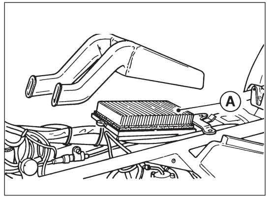
Check the air filter every 5000 km and clean by blowing with compressed air; change every 10.000 km.
This filter is mounted in a special case above the motor group, the saddle and fuel tank must be removed in order to have access to it.

For the above operations it is advisable to apply to a Moto-Guzzi dealer.
27
Interna (long life) NGK PMR8B
Esterna NGK BPR6ES
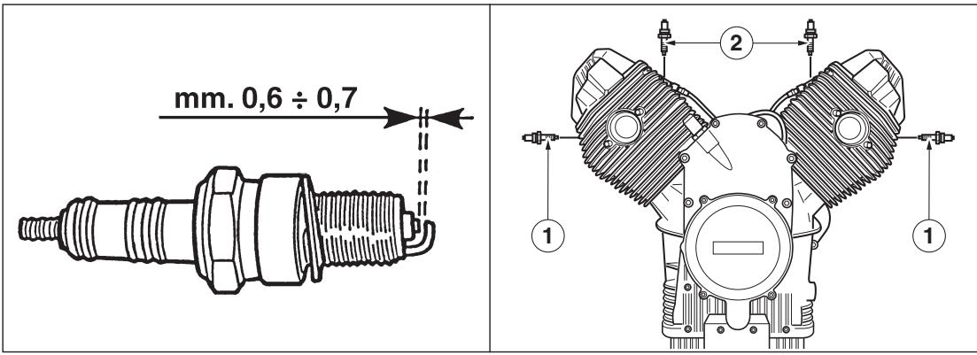
The following instructions apply only to outer spark plugs (1). This vehicle is also fitted with two inner spark plugs (2); contact a Moto Guzzi Authorised Dealer to have them replaced.
Use the following types of spark plug:
Inner (long life) NGK PMR8B
Outer NGK BPR6ES
Spark plug gap: 0.6 ÷ 0.7 ~mm .
Periodically remove the spark plugs for cleaning and checking.
Bougies (fig. 28)
Refit the plugs by hand taking care not to cross thread them, they should screw home easily; it is then recommended to tighten them manually for some turns and to use the provided suitable key, in order to lock them when the engine is cold.
Even if used plugs appear to be in good condition, they should be replaced every 10.000km

N.B. - Values lower than 0.6 ÷ 0.7 mm can compromise the engine life.
WARNING! To avoid
To avoid either malfunctioning or inefficiencies of the ignition system, the spark plug wire connections (spark plug cap) and the spark plugs must be of the recommended type (as original equipment).
Do not make any plug current check if the original spark plug cap are not fitted otherwise the electronic power box would be irreparably damaged. Bear in mind that this also applies to any vehicles equipped with the electronic ignition systems listed below.
The electrical equipment consists of the following:
Battery.
- Starter motor with electro-magnetic ratchet.
Generator-alternator fitted to the front of the crankshaft.
Fuel reserve signal device.
Light switch.
Ignition coil.
Electronic control unit.
Phase and revolution sensor.
Side-stand microswitch.
Voltage regulator.
Fuse box.
Electronic control unit.
Pump control microswitch, coils, electro-injectors.
Starter microswitch.
Headlight.
Tall light.
Direction indicators.
■ Selector indicators.
Light direction indicator, horn and headlamp flasher switch.
Hazard warning lights, switch.
Starter and stop device.
Electric horns - Horn switch.
Warning lights on instrument panel for: neutral indicator (green), side lights on (green), oil pressure (red), main beam (blue), fuel reserve (orange), direction indicators (green).
INSTALLATION ELECTRIQUE
The battery has a 12 voltage, a 18Ah (16Ah USA) capacity and is charged by the alternator.
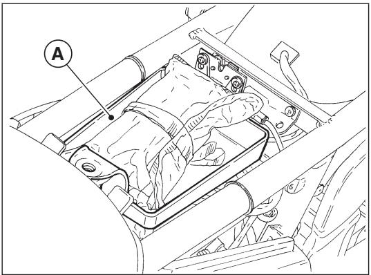
To gain access to the battery:
Remove the rider's saddle;
Lift out the tool box;
The battery is the hermetic type (maintenance-free) and does not need to be checked.
Instructions for recharging
To recharge the battery, use a costant voltage charger set to 14÷ 15V at 25^ .

WARNING
Contains toxic materials (Pb and H_2SO_4
Extremely high current, avoid short circuit. DO NOT charge in a gas tight container. Sealed Lead Battery.
Must be recycled or disposed of properly.

These operations are best carried out by an authorized dealer.

WARNING
Keep the battery out of the reach of children.
Batterie
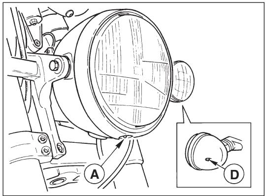
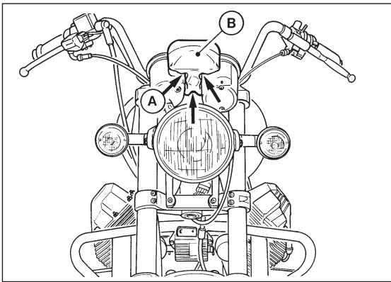
To change the bulbs, unscrew the retaining screw «A» under the headlight unit; remove the light unit and remove the lamp holder.

N.B. - When changing the headlight bulb
(main/dipped beams) take care not to touch
the glass part of the bulb with your fingers.
Unscrew the screws "A" which attach the reflector to the light body; at the same time press the lights inward while rotating them and unscr ew them from the light-sockets.
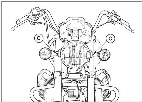
Front and rear direction indicators (figs. 29-30)
Undo the screws «D» holding the reflector to the direction indicator unit. To remove the bulb from the bulb holder, press in and turn.

N.B. - Do not overtighten the reflector retaining screws as this will break the reflec
tor.
30
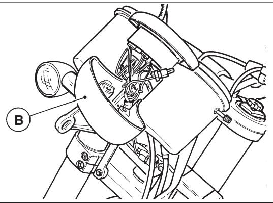
Feu arrriere (fig. 30)
Remove the windshield;
Dismantle the head lamp;
Take out the three screws «A» which fasten the lower cover «B»;
Take out the lower cover B
Take out the lamp holder and replace the lamp.
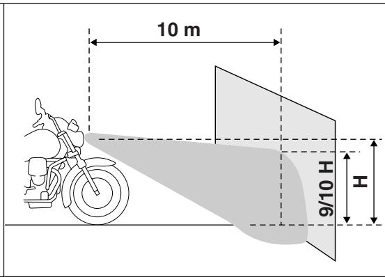
Adjusting the headlight beam (fig. 33)
The headlight beam should always be kept adjusted at the correct height to ensure good visibility and to avoid dazzling on coming traffic. Fot its vertical orientation, loosen two screws «C» that fix the headlight, and move it manually upwards or downwards until the prescribed height.
Dipped and main beam 60/55 W
Side/parking lights 5 W
Tall light:
Number plate, stop light 5/21 W
Direction indicators 10 W
Speedo, rev. counter warning lights 1.2/2 W
Instrument panel warning lights 1.2 W
Ampoules
Phare avant:
Key to wiring diagram
1 Driving beam 60 W (H4 halogen with traffic beam)
2 Parking light 5W
3 Traffic beam 55 W (H4 halogen with driving beam)
4 way Amp connector for front lamp
5 Front direction indicator 10 W, RH
6 Front direction indicator 10 W, LH
7 Instrument panel
8 10-way A Amp connector (instrument panel)
9 10-way B Amp connector (instrument panel)
10 Horn
11 Switch for oil pressure
12 Idle switch
13 Switch for fuel level
14 Heated left grip
15 2-way connector
16 10-way Pakard connector (device LH)
17 LH control device: lights, direction indicators, horn
18 Alternator 12V 350 W
19 Voltage regulator
20 Intermittence
21 Lights relay (MINIRELAY SWITCH)
22 Start relay (MINIRELAY SHUNTING)
23 Starter
24 Battery
25 Rear Stop switch
26 6-way connector for rear light unit
27 Rear direction indicator 10 W, LH
28 Rear direction indicator 10 W, RH
29 Rear stop light 21 W (with parking light)
30 Rear parking light 5 W (with STOP light)
31 Power outlet (15A)
32 Safety fuses range (see table at pag. 204)
33 Hetead grips relay (SWITCHING MINIRELAY)
34 Female Fast-on for side stand switch
35 Safety switch for side stand
36 RH control device, (Ign.-Run, Start, lights)
37 10-way Pakard connector (controls device, RH)
38 Front Stop switch
39 Heated right grip
40 2-way connector
41 Key ignition switch
42 4-way AMP connector
44 Electronic unit IAW 15RC
45 Air temperature sensor
46 3-way diagnosis AMP connector
47 4-way Lambda probe AMP connector
48 Cilynder ignition coil AT, LH (BAE850AK)
49 Cilynder ignition coil AT, RH (BAE850AK)
50 Power relay for injection (MINIRELAY SWITCH)
51 Safety diode
52 Electronic unit relay ECU (MINIRELAY SWITCH)
53 Pompe du carburant
54 Injector, LH (IW031)
55 Injector, RH (IW031)
56 Timing sensor (SEN813)
57 Motor oil temperature sensor (NIC WTS05)
58 Throttle potentiometer (PF3C)
59 Max. pressure sensor inside the electronic unit ECU
60 2-way AMP connector (key closed supply)
61 1-way AMP connector (RPM sensor in the injection side)
202 SCHEMA INSTALLATION ELECTRIQUE
| F1 | Battery recharge | 30A |
| F2 | Key switch | 15A |
| F3 | Driving beam, traffic beam, Stop | 20A |
| F4 | Dipped lights, Direction indicators | 5A |
| F5 | Power outlet | 15A |
| F6 | IAW15RC | 5A |
| F7 | Pump, coils, injectors | 10A |
FUSIBLES
Bianco-Marrone = White-Brown
Nero-Grigio = Black-Grey
Rosso-Bianco = Red-White
Rosso-Blu = Red-Blue
Rosso-Verde = Red-Green
Marrone-Nero = Brown-Black
Bianco-Blu = White-Blue
Bianco-Verde = White-Green
Arancio = Orange
Azzurro = Azur
Bianco = Blanc
Giallo = Jaune
Grigio = Gris
Marrone = Marron
Nero = Noire
Rosa = Rose
Rosso = Rouge
Verde = Vert
Viola = Violet
Marrone-Nero = Marron-Noir
Bianco-Blu = Blanc-Bleu
Bianco-Verde = Blanc-Vert
Arancio = Orange
Azzurro = Hellblau
Bianco = Weiss
Giallo = Gelb
Grigio = Grau
Marrone = Braun
Nero = Schwarz
Rosa = Rosa
Rosso = Rot
Verde = Grun
Viola = Violett
Bianco-Azzurro = Weiss-Hellblau
Bianco-Giallo = Weiss-Gelb
Bianco-Marrone = Weiss-Braun
Bianco-Nero = Weiss-Schwarz
Blu-Nero = Blau-Schwarz
Giallo-Nero = Gelb-Schwarz
Nero-Grigio = Schwarz-Grau
Rosso-Bianco = Rot-Weiss
Rosso-Blu = Rot-Blau