
SANTORIN 25 - Loudspeaker CABASSE - Free user manual and instructions
Find the device manual for free SANTORIN 25 CABASSE in PDF.
| Product Type | Active subwoofer |
| Brand | CABASSE |
| Model | SANTORIN 25 |
| Dimensions (H × W × D) | 42 × 36 × 38 cm |
| Weight | 19 kg |
| Power supply | 115 / 230 V AC, 50 / 60 Hz |
| Maximum consumption | 165 W |
| Speaker driver | 25 cm (model 2SS20) |
| Frequency response | 34 – 150 Hz (in semi-reverberant room) |
| Maximum impulse pressure | 111 dB RMS |
| Amplifier nominal power | 250 W |
| Peak power | 750 W |
| Crossover frequency | Adjustable from 40 to 150 Hz |
| Phase selector | Normal phase / inverted phase |
| Input connectors | 2 low level (LINE IN), 2 high level (HIGH LEVEL INPUT) |
| Output connectors | 2 low level (LINE OUT), 2 high level (HIGH LEVEL OUTPUT) |
| Features | Active subwoofer, automatic standby mode, volume adjustment (LEVEL), crossover frequency adjustment (CROSSOVER FREQUENCY) |
| Maintenance | Disconnect before cleaning, use a damp cloth |
| Safety precautions | Do not expose to water or humidity, do not block ventilation openings, avoid electrical overloads |
| Spare parts | Use only original CABASSE parts |
| Consumer service | France : 02 98 05 13 13, service-conso@cabasse.com |
| Manual | Available in PDF at notice-facile.com |
Frequently Asked Questions - SANTORIN 25 CABASSE
User questions about SANTORIN 25 CABASSE
0 question about this device. Answer the ones you know or ask your own.
Ask a new question about this device
Download the instructions for your Loudspeaker in PDF format for free! Find your manual SANTORIN 25 - CABASSE and take your electronic device back in hand. On this page are published all the documents necessary for the use of your device. SANTORIN 25 by CABASSE.
USER MANUAL SANTORIN 25 CABASSE
SUBWOOFERS OPERATING INSTRUCTIONS
Attention aux chariots de manutention
Thank you very much for choosing Cabasse speakers. Please read carefully these instructions before setting up your speakers.
SAFETY INSTRUCTIONS
Explanation of graphical symbols - The lightning flash with arrowhead symbol, within an equilateral triangle, is intended to alert you to the presence of uninsulated
"dangerous voltage" within the product's enclosure that may be of sufficient magnitude to constitute a risk of electric shock to persons.
The exclamation point within an equilateral triangle is intended to alert you to the presence of important operating and maintenance (servicing) instructions in the literature accompanying the appliance.
Instructions - Carefully read through all the safety and operating instructions before switching on any device for the first time.
Keep these instructions in mind - They will be constantly referred to through this manual.
Pay special care to warnings - All the warning labels on the product or warning notes in the user's manual must be followed.
Follow the instructions - Follow carefully all the installation and operation instructions.
Cleaning - Always take off the power cord before cleaning the device. Do not use cleaning solvent, whether liquid or air spray. Using a soft damp cloth is recommended.
Accessories - To avoid incidents, only use accessories expressly recommended by Cabasse.
Water and moisture - The product shall not be used in damp or wet locations, such as humid basements, next to a bathtub, sink, swimming pool or any other similar conditions.
Carts and Stands - The appliance should be used only with a cart or stand that is recommended by the manufacturer.
Portable cart warning
Installation on a piece of furniture and stands - Do not place this device on an unsteady surface, i.e. a stand, tripod, table, shelf, etc. It may fall and cause serious injury to a nearby child or adult.
Ventilation outlets - The device shall not be placed in a position that restrains the operation of its fans. Avoid installing the device on a bed, couch, blanket or other similar surfaces that may prevent the appropriate air flow. Do not install the device in a confined space, such as a book shelf or other piece of furniture, that could prevent sufficient air from flowing freely.
Power - The device shall only be connected to a source of power compliant to the one described in this manual or on relevant printed labels on the product. If you are not sure of the type of power available, please contact your reseller or the local power company.
Power cords - The power cords must be laid out in such a way that they cannot be walked on, pinched, bent under other devices. Also pay special attention to the matching of the plugs and the connection of the cord to the device.
Lightning - For better protection against lightning or if the device must remain unused for long stretches of time, unplug the power cord and antenna jack. This minimizes potential damages due to lightning or line surges.
Overloads - Avoid overloading the power plugs, extension cords or power relays. This could result in fire or electric shocks.
Foreign bodies and liquids - Avoid letting foreign materials or liquids enter the device. They could cause fire or electric shocks. Never spill any liquid on the device.
Maintenance - Users must never attempt to maintain the device on their own, except for those maintenance operations described in this manual. Any task beyond regular user maintenance must be performed by qualified service operators.
Troubleshooting - You must unplug your device from the power supply and have it checked by a qualified technician if:
The power supply or the plug is damaged.
Foreign bodies or liquid penetrated the device.
The device was exposed to dripping or splashing.
The device does not seem to work correctly under normal operating conditions. Only operate the controls described in this manual. Any other operation could damage the device and require on-site visit of a qualified technician.
The device has fallen or its housing is damaged.
The performances of the device are strongly altered.
Spare parts - If spare parts are needed to repair the device, make sure that the technician followed the manufacturer's recommendations or that the replacing parts feature the same specifications as the original ones. Non-compliant parts can result in multiple damages, including fire or electric shocks.
Checks - After any servicing of the device, ask the technician to perform appropriate testing to make sure that the device works safely.
Exposure to high temperatures - The device should be kept away from heating sources, such as radiators, heaters, amplifiers or any other similar item likely to make the operating temperature rise excessively.
Applicable for USA, Canada or where approved for usage
Caution! To prevent electric shock, match wide blade plug to wide slot, insert fully.
UNPACKING
After opening the top carton flaps, remove the grille. Then fold the carton flaps right back and invert the carton contents. Lift the carton clear of the contents and remove the inner packaging from the speakers. We suggest you to retain the packing for future use.
POSITIONING
Speakers positioning
Our speakers have been designed to function in a vertical position. The majority of our models are delivered with a set of decoupling spikes or cones, these accessories are to be screwed in the inserts under the cabinets. These accessories ensure the stability of the speaker while limiting resonance coming from certain types of grounds like wood floors.
Powerful drivers generate magnetic fields that can extend beyond the boundaries of the speaker cabinet. We recommend you keep magnetically sensitive articles (TV, computer screen, computer discs, audio and video tapes, swipe cards...) at least 1.5 ft (50 cm) away from the speaker. Cabasse centre speakers or the ones marked «TV» are not concerned with this, being magnetically shielded.
Positioning speakers in a room
Optimal positioning for a 2.1 or stereo with a subwoofer system
For a stereo listening with 2 speakers or 2 satellites and 1 subwoofer, we recommend you to place the subwoofer in the front listening area. The placement of the subwoofer against a wall reinforces the low frequencies and limit the reflections from 80 to 200Hz . However to obtain the best results, it is always necessary to carry out tests according to the acoustic of the room.
Optimal positioning for a 5.1
or home theatre system
Setting up a multi-channel Audio-Video system requires great care when positioning the specific AV speakers.
The centre speaker should be placed as close as possible to the screen and where it sounds best from your listening spot while offering the optimal picture/dialogues cohesion. Theoretically, the screen should be located within a virtual triangle formed by the acoustical centres of the main speakers and the centre speaker. Practically speaking, this means that the principal speaker should be placed above the screen if the main speakers are below it, and below the screen if the main speakers are above. The centre speaker should also, if possible, be set slightly back from the others, so that it is located at the same distance from the listener as the main speakers.
- The rear speakers or surround should be placed against the side walls, at listening height. They should not be positioned far behind the listening zone.
The subwoofer should be placed in the front listening area, its position against a wall reinforces the extreme low register and limits the reflections between 80 and 200Hz . However to obtain the best result, it is always necessary to carry out tests according to the acoustics of the room.
Your AV processor enables the adjustment in level and delay of each of the 5/6/7 channels of your system. Fine-tuning is necessary to obtain a perfect sound stage.
Turn off all the amplifiers before interconnecting them to the loudspeakers. In order to connect loudspeakers properly, it is most important to keep in mind the following two factors: cable section and phase.
CONNECTION
Cable section
To get the full sonic potential of Cabasse loudspeakers and avoid power losses, the cables connecting the speakers to the power amplifier must
| Lenght between amplifier and loudspeakers | recommended section |
| 4.5 m | 1.5 mm² |
| 6 m | 2 mm² |
| 7.5 m | 2.5 mm² |
| 9 m | 3 mm² |
| 12 m | 4 mm² |
have the lowest possible electrical resistance. To help you in choosing the correct cable gauge, follow diagram.
Phase
In order to maintain the phase relationship and frequency balance of the loudspeaker system, both loudspeakers must be properly connected to the power amplifier. When properly connected, the cones of the drivers of both loudspeakers will move in the same direction when driven by identical speakers will move in the same signals. If the cones move in opposite directions, the resulting out of phase signals will create a perceptible power loss, particularly in the low frequencies. The stereophonic message will also be degraded. Amplifier and speaker manufacturers typically indicate connection polarity in one of two ways: red and black or plus and minus. In either case, always connect red or plus to red or plus and black or minus to black or minus. Connections should be identical for both channels. To check that the speakers are in correct phase, switch the system to mono while music is being played. If the amplifier does not have a phase inversion switch, it will be necessary to change over the
connections on one only of the loudspeakers. If in correct phase, the image should be distinctly located between the loudspeakers with a slight loss of bass and low midrange level. If the image is confused and not centrally located and there is a drastic loss of bass and low midrange level, recheck your connections.
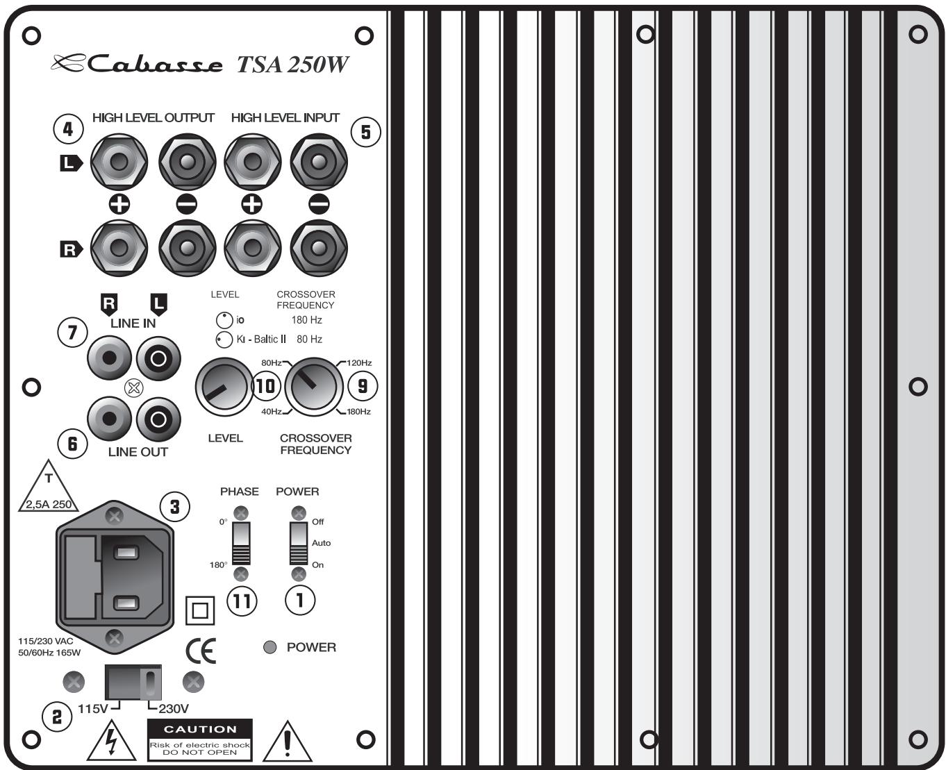
2 possibilities are offered to connect the subwoofer with your system:
the low level one requiring the use of the CINCH RCA LINE IN ⑦ and LINE OUT ⑧ terminals and shielded coaxial connectors,
- the high level one requiring the use of the speaker HI LEVEL INPUT ⑤ and HI LEVEL OUTPUT ④ terminals, and standard loudspeaker cables.
The inputs are stereo ones, the mix of the L (left) and R (right) low frequencies being done by the amplifier of the subwoofer. If the input signal is already mono, only one input L (left) or R (right) should be used.
Interconnections with the CINCH RCA connectors
Connections to the LINE IN ⑦ connectors
If your preamplifier or your integrated amplifier is fitted with a stereo low-level output, then connect its L (left) and R (right) outputs to the L (left) and R (right) LINE IN ⑦ inputs of the subwoofer.
If your amplifier offers a one mono output, connect it to either the L (left) or the R (right) subwoofer LINE IN ⑦ inputs.
Connections from the LINE OUT ⑥ connectors
The signal from the L (left) and R (right) LINE OUT ⑧ plugs is the one being brought in by the L (left) and R (right) LINE IN connectors filtered at 80Hz .
These outputs can thus be used to bring the signal to the amplifier powering the main loudspeaker.
Interconnections with the speaker terminals
Connections to the HI LEVEL INPUT ⑤ plugs
If the preamp section of your Hi-Fi or audio-video system is not fitted with a lowlevel output, you should then connect the subwoofer by using its loudspeaker terminals. When connecting the L (left) and R (right) speaker outputs of your amplifier to the HI LEVEL INPUT ⑤ plugs of the subwoofer, be careful not to cross (-) and (+) cord of either L (left) or R (right) channel. Such a phase inversion might damage your main amplifier.
Connections from the HI LEVEL OUTPUT ④ plugs
These outputs can be used to bring the signal to the main loudspeaker systems or to a second subwoofer in a parallel mono configuration. In the last lay-out, the L (left) and R (right) HI LEVEL OUTPUT ④ terminals must be connected to the L (left) and R (right) HI LEVEL INPUT ⑤ ones of the second subwoofer. The input signal must then arrive into the first subwoofer by its L (left) and R (right) HI LEVEL INPUT ⑤ terminals.
The signal from the L (left) and R (right) HI LEVEL OUTPUT ④ plugs, filtered at 200Hz is the one being brought in by the HI LEVEL INPUT ⑤ connectors.
These outputs can thus be used to bring the signal to the main loudspeaker systems.
Power supply
The AC IN ③ cord must be connected to the mains to supply the subwoofer. The selection of the right voltage 115 V - 230 V is done with the selector 150 V - 230 V ⑧ . Switch POWER ① , on AUTO or ON.
With the switch on the AUTO position, the unit will mute after a few minutes without input signal. The system turns on automatically when signal comes back.
Attention, before operating the unit, be sure that the operating voltage of your unit is identical with that of your local power voltage.
ADJUSTMENTS
LEVEL 10
For a first volume adjustment, position the CROSSOVER FREQUENCY 9 at around 120Hz , and turn slowly the volume LEVEL 10 clockwise from minimum level up to a position where you feel that the subwoofer sound level is appropriate. A check of the level adjustment will be necessary after following steps.
This potentiometer adjusts the cut-off frequency which determines the working bandwidth of the subwoofer. This adjustment should be done according to the specifications of the main speakers and the room acoustics. Choose the best frequency after various listening tests.
PHASE ⑪
For a better sound integration of the subwoofer in the main system, the PHASE (1) of the subwoofer might have to be inverted (180° position), depending on the distance between the subwoofer and the main speakers. You have to check the PHASE (1) each time you move your speakers and each time you adjust the CROSSOVER FREQUENCY (9). Attention, if you use 2 subwoofer, both phase switches must be on the same position.
SPECIFICATIONS & TECHNICAL DATA
Santorin 21
Band pass active subwoofer
Drive unit: 0.21cm (8 in)-type 21MT3
Frequency bandwidth:
35-160 Hz in semi-reverberating chamber
Maximum RMS SPL: 108 dB
Maximum output power: 250 W
Peak power: 750 W
Lowpass cut-off frequency: 40 to 160Hz
Phase switch: 0^ normal - 180^ reverse
Input: 2 low level - 2 high level
Voltage: 115 / 230VAC - 50 / 60Hz
Maximum power consumption: 165 W
Dimensions (h x w x d): 33 x 33 x 36 cm - 13 x 13 x 14 in
Weight: 13kg - 29lb
Santorin 25
Active subwoofer
Drive unit: 0.25cm (10 in)-type 25S20
Frequency bandwidth:
34-150 Hz in semi-reverberating chamber
Maximum RMS SPL: 111 dB
Maximum output power: 250 W
Peak power: 750 W
Lowpass cut-off frequency: 40 to 150Hz
Phase switch: 0^ normal - 180^ reverse
Input: 2 low level - 2 high level
Voltage: 115 / 230VAC - 50 / 60Hz
Maximum power consumption: 165 W
Dimensions (h x w x d): 42 X 36 X 38 cm - 16.5 x 14 x 15 in
Weight: 18kg - 39lb
Because of technical improvements already under way in our constant search for optimum quality, Cabasse reserves the right to modify all the models presented in specification sheets, advertising materials and manuals without prior notice.
Our web site www.cabasse.com will give you the specific adjustments we recommend for the use of our active subwoofoers.
LINE OUT 6 Anschlüsse
HIGH LEVEL INPUT ⑤ Anschlüsse
- SAFETY INSTRUCTIONS
- Applicable for USA, Canada or where approved for usage
- UNPACKING
- POSITIONING
- Speakers positioning
- Positioning speakers in a room
- Optimal positioning for a 2.1 or stereo with a subwoofer system
- Optimal positioning for a 5.1
- or home theatre system
- CONNECTION
- Cable section
- Phase
- Interconnections with the CINCH RCA connectors
- Connections to the LINE IN ⑦ connectors
- Connections from the LINE OUT ⑥ connectors
- Interconnections with the speaker terminals
- Connections to the HI LEVEL INPUT ⑤ plugs
- Connections from the HI LEVEL OUTPUT ④ plugs
- Power supply
- ADJUSTMENTS
- LEVEL 10
- PHASE ⑪
- SPECIFICATIONS & TECHNICAL DATA
- Santorin 21
- Band pass active subwoofer
- Frequency bandwidth:
- Santorin 25
- Active subwoofer
- LINE OUT 6 Anschlüsse
- HIGH LEVEL INPUT ⑤ Anschlüsse
Brand : CABASSE
Model : SANTORIN 25
Category : Loudspeaker