
DMS 700 - Wireless Microphone System AKG - Free user manual and instructions
Find the device manual for free DMS 700 AKG in PDF.

| Product type | Digital wireless microphone system (receiver DSR 700, transmitters DPT 700 and DHT 700) |
| Carrier frequency range | Band 1: 548.1 – 697.9 MHz / Band 2: 710.1 – 864.9 MHz |
| Switching bandwidth | ≤ 155 MHz (depending on country) |
| Audio bandwidth | 25 – 20,000 Hz (±3 dB) |
| Distortion (THD) | ≤ 0.05 % |
| Signal-to-noise ratio (A-weighted) | Analog XLR: typ. 115 dB(A) / Digital AES-EBU: typ. 120 dB(A) |
| Latency | 4 ms |
| Encryption | Yes |
| Receiver type | Superheterodyne, true digital diversity |
| Receiver dimensions (W x H x D) | 480 x 43 x 200 mm (1U rack) |
| Receiver weight | 2.3 kg |
| Receiver power supply | 90 – 240 VAC, 50-60 Hz, 0.4 A |
| Audio outputs | 2 x XLR balanced analog, 2 x 6.35 mm jack unbalanced, 1 x XLR AES-EBU digital |
| RF output power (transmitters) | 10, 20, 30, 50 mW (depending on country, adjustable via software) |
| Battery life (transmitters) | ≥ 8 h with 2 LR6 AA batteries (alkaline or NiMH >2100 mAh) |
| DPT 700 transmitter dimensions | 83.5 x 64.1 x 22 mm |
| DPT 700 transmitter weight | 82 g (without batteries) |
| DHT 700 transmitter dimensions | 52 (ø) x 231 mm |
| DHT 700 transmitter weight | 336 g |
| Audio processing functions | Low cut (0-300 Hz), 3-band equalizer, dbx® compressor and limiter |
| Cleaning | Soft cloth dampened with water; disconnect power before cleaning |
| Operating temperature | -10 °C to +55 °C |
Frequently Asked Questions - DMS 700 AKG
User questions about DMS 700 AKG
0 question about this device. Answer the ones you know or ask your own.
Ask a new question about this device
Download the instructions for your Wireless Microphone System in PDF format for free! Find your manual DMS 700 - AKG and take your electronic device back in hand. On this page are published all the documents necessary for the use of your device. DMS 700 by AKG.
USER MANUAL DMS 700 AKG
Please read the manual before using the equipment!
for purchasing an AKG product. This manual contains important instructions for setting up and operating your equipment. Please take a few minutes to read the instructions below carefully before operating the equipment. Please keep the manual for future reference. We hope you enjoy using your system!
Symbols Used

The lightning flash with arrowpoint in an equilateral triangle means that there are dangerous voltages present within the unit.

The exclamation point in an equilateral triangle on the equipment indicates that it is necessary for the user to refer to the User Manual. In the User Manual, this symbol marks instructions that the user must follow to ensure safe operation of the equipment.
Important Note!

- AKG continually improves the internal firmware of the DMS 700 system in order to meet changing customer needs in the best possible way. Should your system use a different firmware version than the one described in this user manual, some functions may differ from the related instructions.
- To find out the actual firmware version implemented in your system, please check the menu. The firmware version described in this user manual is stated on the cover page.
- Before you read on, we recommend comparing the receiver firmware version against the version described in the manual. If the two versions are not identical, please visit www.akg.com to find out about the latest changes.
FCC Statement
The DHT 700 D5, DHT 700 C5, and DPT 700 have been tested and found to comply with the limits for a low-power auxiliary station pursuant to Part 74 of the FCC Rules. The DSR 700 has been tested and found to comply with the limits for a Class B digital device, pursuant to Part 15 of the FCC Rules. These limits are designed to provide reasonable protection against harmful interference in a residential installation. This equipment generates, uses, and can radiate radio frequency energy and, if not installed and used in accordance with the instructions, may cause harmful interference to radio communications. However, there is no guarantee that interference will not occur in a particular installation. If this equipment does cause harmful interference to radio or television reception, which can be determined by turning the equipment off and on, the user is encouraged to try to correct the interference by one or more of the following measures:
Reorient or relocate the receiving antenna.
- Increase the separation between the equipment and the receiver.
- Connect the equipment into an outlet on a circuit different from that to which the receiver is connected.
- Consult the dealer or an experienced radio/TV technician for help.
Shielded cables and I/O cords must be used for this equipment to comply with the relevant FCC regulations.
Changes or modifications not expressly approved in writing by AKG Acoustics may void the user's authority to operate this equipment.
The DRS 700 complies with Part 15 of the FCC Rules. Operation is subject to the following two conditions: (1) this device may not cause harmful interference, and (2) this device must accept any interference received, including interference that may cause undesired operation.
1 Safety and Environment 4
Safety 4
Environment 4
2 Packing List 5
3 General 6
DMS 700 6
4 Setting Up. 8
Inserting Batteries into the Transmitter 8
Connecting Antennas 8
Positioning the Receiver 8
Connecting the Receiver to a Mixer/Amplifier 8
Ground Lift (16, 19) 9
Connecting the Receiver to Power 9
Transmitter SILENT Mode 9
Receiver LOCK Mode 9
Optional external MUTE switch 9
5 Operating Notes 10
SELECT Control (5) 10
CH1/CH2 Buttons(10/12) 10
BACK Button (4) 10
DSPButton(2) 10
Checking the Audio Signal - Headphones CH1 / CH2 Buttons (6) 10
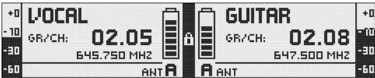
6 Display 11
Main Window 11
Channel Information Window 11
Battery Status Indication 11
Audio Meter 11
MUTE Indication (F) 11
Antenna Indication 12
Status & Warning Messages 12
7 DSR 700 Menu 14
QUICK SETUP 15
CHANNEL 16
AUDIO 17
ENVIR. SCAN 18
REHEARSAL 18
UTILITY 19
8 DPT 700/DHT 700 Menus. 20
Standard Startup 20
Silent Mode Startup 21
9 Function Description 22
QUICK SETUP 22
CHANNEL Menu 22
AUDIO Menu 23
ENVIRONMENT SCAN 24
REHEARSAL -Sound Check. 24
UTILITY Menu 24
10 Cleaning 25
11 Troubleshooting 26
12 Specifications 28
DMS 700 Digital Microphone System. 28
DSR 700 Digital True Diversity Receiver 28
DPT 700 Digital Bodypack Transmitter 28
DHT 700 Digital Handheld Transmitter 29
1 Safety and Environment
Safety
- Do not spill any liquids on the equipment and do not drop any objects through the ventilation slots in the equipment.
The equipment may be used in dry rooms only. - The equipment should be opened, serviced, and repaired by authorized personnel only. The equipment contains no user-serviceable parts.
- Before connecting the equipment to power, check that the AC mains voltage stated on the equipment is identical to the AC mains voltage available where you will use the equipment.
- Operate the equipment off voltages between 90 VAC and 240 VAC only. Using a different power voltage may cause serious damage to the unit!
- If any solid object or liquid penetrates into the equipment, shut down the sound system immediately. Disconnect the power cable from the power outlet immediately and have the equipment checked by AKG service personnel.
- Do not place the equipment near heat sources such as radiators, heating ducts, or amplifiers, etc. and do not expose it to direct sunlight, excessive dust, moisture, rain, mechanical vibrations, or shock.
- To avoid hum or interference, route all audio lines, particularly those connected to the microphone inputs, away from power lines of any type. If you use cable ducts or conduits, be sure to use separate ones for the audio lines.
- Clean the equipment with a moistened (not wet) cloth only. Be sure to disconnect the equipment from the power outlet before cleaning the equipment! Never use acidic or scouring cleaners or cleaning agents containing alcohol or solvents since these may damage the enamel and plastic parts.
- Use the equipment for the applications described in this manual only. AKG cannot accept any liability for damages resulting from improper handling or misuse.
Environment

- Be sure to dispose of used batteries as required by local waste disposal rules. Never throw batteries into a fire (risk of explosion) or garbage bin.
- The packaging of the equipment is recyclable. Disposse of the packaging in an appropriate container provided by the local waste collection/recycling entity and observe all local legislation relating to waste disposal and recycling.
-
When scrapping the equipment, remove the batteries, separate the case, circuit boards, and cables, and dispose of all components in accordance with local waste disposal rules.
-
Check that the package contains all the parts listed below. If anything is missing, please contact your AKG dealer.
-
1 x DSR 700 receiver
2 x BNC UHF antennas
1x EU-standard IEC power cord
1xUS-standard IEC power cord
DSR 700
DPT 700 transmitter
2 x LR6 AA dry batteries
DPT 700
DHT 700 transmitter
2 x LR6 AA dry batteries
- Stand adapter
Color code
- Windscreen with color code strips
Optional Accessories
- SRA 2 W - Passive directional antenna
- SRA 2 B/W - Active directional antenna
- RA 4000 W - Passive omnidirectional antenna
- RA 4000 B/W - Active omnidirectional antenna
PS 4000 W - Active antenna splitter - AB 4000 - Antenna booster
- MK PS - Antenna cable, 2 feet/65 cm
MKA 20 - Antenna cable, 66 feet/20 m
0110E01890 - Front-mount antenna cable
Antenna Accessories
- For more options and antenna accessories, please refer to the current AKG catalog or folder, or visit www.akg.com. Your dealer will be glad to help.
DMS 700
The DMS 700 wireless microphone system is comprised of the DSR 700 stationary digital true-diversity receiver, handheld transmitters DHT 700/C with an AKG C 5 microphone element and DHT 700/D with an AKG D 5 microphone element, and the DPT 700 bodypack transmitter. The receiver and transmitters operate in a 155MHz (max.) sub-band of each frequency set within the UHF band from 548MHz to 865MHz . You can select the receiving frequency from pre-programmed frequency groups and sub-channels of your receiver or set it directly in 25kHz -increments. Both the handheld and bodypack transmitters are set to the parameters selected on the receiver via infrared transmission.
DSR 700
Controls
Refer to page i.
- POWER: ON/OFF switch
- DSP button
- Graphic display
- BACK button
- SELECT control (turn left/right, push)
- Headphone buttons (CH1, CH2)
- Headphone output, 14 /6.3mm jack socket
- Infrared data synchronization window
- RF signal level LED meter
- Channel selection for channel CH1
- Backlit status ring for channel CH1 & CH2 (red=warning, green=OK)
- Channel selection for channel CH2
- Opening for antenna front mounting
- BNC socket, antenna input A
- BNC socket, antenna input B
- GND-Lift XLR output channel CH1
- XLR socket (male), analog audio output CH1, balanced
- 14'' / 6.3mm jack socket, analog audio output CH1, unbalanced
- GND Lift XLR output channel CH2
- XLR socket (male), analog audio output CH2, balanced
- 14 /6.3mm jack socket, analog audio output CH2, unbalanced
- Data interface, RJ11 socket for connecting the receiver to a computer via a HUB 4000 Q
- BNC socket, AES-EBU wordclock IN (48kHz)
- XLR socket (male), digital AES-EBU audio output CH1 & CH2 (48 kHz)
- IEC mains connector (90 to 240 VAC)
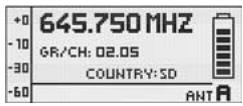
Graphic Display Refer to page i.
A. Alphanumeric name line
B. Current group & channel numbers
C. 7-digit transmitter battery status indicator
D. LOCK symbol
E. Audio signal level meter
F. MUTE symbol
G. Current frequency line
H. Currently active antenna line
- Graphic display
- Mute switch
- 1 / 4 wave antenna
- Infrared window for data synchronization
- Status LED (red=warning, green=OK)
- Power ON/OFF button
- Battery compartment cover
- 3-pin male mini-XLR (TB3M) audio input for microphones and instruments
- Battery compartment for two 1.5 V LR6 AA batteries or 1.2 V AA NiMH rechargeable batteries (>2100 mAh)
- 0.1"/2.5-mm jack socket for external mute switch
- Charging contacts
- Battery compartment release buttons
DPT 700
Controls
Refer to page i.
A. Alphanumeric name line
B. Current group & channel numbers
C. 7-digit battery status display
D. Country or RF output level line
E. Active encryption symbol
F. Active mute symbol
Graphic Display
Refer to page i.
- Graphic display
- Mute button
- Color code, charging contacts, helical antenna
- Infrared window for data synchronization
- Status LED (red=warning, green=OK)
- Power ON/OFF button
- Battery compartment cover
- Microphone element
- Battery compartment for two 1.5 V LR6 AA batteries or 1.2 V AA NiMH rechargeable batteries (>2100 mAh)
DHT 700
Controls
Refer to page ii.
A. Alphanumeric name line
B. Current group & channel numbers
C. 7-digit battery status display
D. Country or RF output level line
E. Active encryption symbol
F. Active mute symbol
Graphic Display
Refer to page ii.
| • Prior to using your DMS 700, make certain that the transmitter and receiver are tuned to the same frequency. | |
| Inserting Batteries into the Transmitter | 1. Open the battery compartment cover (9).2. Insert the supplied battery into the battery compartment, aligning the battery according to the polarity symbols. If you insert the battery the wrong way, the transmitter will not be powered.3. Close the battery compartment cover (9). |
| Connecting Antennas | The supplied 1/4-wave antennas can be mounted quickly and easily and are suitable for applications where a direct line of sight between the transmitter and the receiver antenna is available and a wire-less microphone system is to be used without a lot of installation work. |
| Remote Antennas | • You should use remote-mounted antennas if the receiver's position doesn't allow the best reception. - Connect the remote antennas to the BNC sockets (14, 15) on the receiver rear panel. - Use RG58 cable to connect the antennas. - For details on antennas, accessories, and frequency planning support visit our website at www.akg.com. |
| Antenna Front-mount Cable | • Use the BNC extension cable (AKG part #0110E01890) for mounting the 1/4-wave antennas on the front panel (13). |
| Positioning the Receiver | Signal reflections off metal objects, walls, ceilings, etc. or the shadow effects of musicians and other people may weaken or block the direct transmitted signal. For best results, place the receiver or remote antennas as follows: • Place the receiver/antennas near the performance area (stage). Make sure, though, that the transmitter won't be used within 10 ft (3 m) of the receiver. Optimum separation is at least 16 ft. (5 m). Check that you can see the receiver from where you will be using the transmitter. Shadow effects caused by people or objects can disrupt the radio link. • Place the receiver at least 5 ft. (~1.5 m) away from any large metal objects, walls, scaffolding, ceilings, etc. • You can use the receiver either free-standing or mounted in a 19" equipment rack. • If you install one or more receivers into a 19" rack, either mount the supplied antennas on the receiver front panel(s) or use remote antennas. This is the only way to ensure optimum reception quality. |
| Connecting the Receiver to a Mixer/Amplifier Analog output | You can connect the receiver's two analog XLR (17, 20) and two analog 1/4"/6.3mm jack (18, 21) outputs at any time. Use the receiver's AUDIO Menu to adjust the output level as needed. • Connect the audio output to the desired input: a) BALANCED XLR-output - microphone input: set the output level switch to "-30 dB". b) BALANCED XLR-output - line input: set the output level switch to "0 dB". c) UNBALANCED 1/4" output - unbalanced 1/4" microphone or line input jack. |
| Digital Output For details on the AES-EBU output visit www.akg.com. | • Use the AES-EBU digital balanced XLR (24) output to feed the audio signals of both receivers to an AES-EBU digital input. The built in A/D converter supports a sampling rate of 48 kHz. You can connect an external 48 kHz clock generator to the Wordclock IN (23) BNC socket to synchronize all your digital si-nals. |
The receiver will automatically detect an external 48kHz clock and will use this clock for the A/D conversion. You can check the Wordclock status in the Channel Information window.
This switch allows you to remove hum caused by ground loops.
- To open the chassis ground connection, press the GROUND LIFT button to the LIFT position. You can check the GND LIFT status in the Channel Information window.
- Check that the AC mains voltage stated on the rear panel is identical to the AC supply voltage available where your system will be used. Using the power supply with a different AC voltage may cause damage to the unit.
- Plug the power cord into the AC IN socket (25) on the receiver's rear panel and the other end of the power cord into a convenient power outlet.
We recommend setting the carrier frequency in SILENT mode only (RF OFF).
To engage SILENT mode, push and hold the MUTE switch (2) while turning on (6) the transmitter. This is the only way to make sure you won't go "on air" on a frequency that is not allocated or

coordinated and risk "jamming" or interfering with some other RF device or wireless system.
The receiver is electronically locked so that you won't make any unintended adjustments. The "LOCK" label (D) is shown on the display.
- To enter SETUP mode, press and hold the SELECT control (5) until the "LOCK" label disappears. After approximately 4 minutes with no action, the receiver will automatically switch into LOCK mode.
The optional RMS 4000 Remote Mute Switch allows mating of the transmitter if it is mounted in a position where it is difficult or impossible to use the "on-board" MUTE switch.
Ground Lift (16, 19)
Connecting the Receiver to Power

Important!
Transmitter SILENT Mode
Receiver LOCK Mode
Optional external MUTE switch
5 Operating Notes
SELECT Control (5)
Controls the various operating parameters of the receiver. The SELECT control has the following functions:
LOCK Mode:
- Long push: Unlocks receiver (switches to SETUP mode).
- Short push: Confirms status and warning messages.
- Turn left or right: No function.
SETUP Mode:
- Long push: Locks the receiver (switches to LOCK Mode).
- Short push: Calls up the selected menu or confirms a selected setting.
- Turn left or right: Select menus or change the selected setting.
CH1/CH2 Buttons (10/12)
Depending on the current menu the channel keys have different functions.
LOCK Mode:
SETUP Mode:
- General View: Call up the channel information window.
- General View: Call up the channel information window.
- Quick Setup Menu: From the CHANNEL LIST, you can directly select and synchronize any open channel.
- Channel Menu: You can directly open a sub-menu (Frequency, Group/Channel, Name...) with the desired channel. The channel sub-menu lets you select a different channel.
Audio Menu: From the GAIN, DSP, and ATTENUATION PAD sub-menus, CH1 and CH2 let you select receiver channel CH1 or CH 2.
Rehearsal Menu: Select the displayed graph.
BACK Button (4)
A short push will close the current menu and all unconfirmed values are erased.
Holding the BACK key will close all menus, all unconfirmed values are erased and the general window is activated.
DSP Button (2)
The DSP button allows you to bypass the LOW CUT, EQ, COMPRESSOR, and LIMITER for each channel individually.
Checking the Audio Signal-Headphones CH1 and CH2 Buttons (6)
- To monitor the audio signal, connect headphones with a 14 /6.3mm TRS plug to the headphones output (7).
- To activate the audio output, push the headphones CH1 or CH2 button next to the headphones socket briefly.
-
To deactivate the audio push the headphones CH1 or CH2 button for more than 1 second.
-
You can adjust the headphone volume with the SELECT control directly after pushing the headphones section CH1 or CH2 button.
The general window shows all necessary parameters for operation. In addition to a freely-selectable name, the current frequency, the current group and channel, you can check the audio level, the active antenna, and the remaining use time of the transmitter battery. In case of a critical fault condition (audio mute, low battery, audio clip) you will see a warning message.
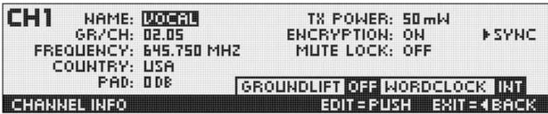
Channel Information Window
The Channel Information window provides a quick overview of the tuning parameters (group/channel, frequency, name, country, attenuation pad, transmission power, encryption, and mute lock). All these parameters can be set and synchronized. The GROUNDLIFT and WORDCLOCK fields indicate the related current status.
- To call up the channel information window, simply push the CH1 or CH2 button from the general window.
The battery symbols on the transmitter (C) and receiver (C) let you check the transmitter's remaining battery capacity at a glance. Each segment equals approximately 1 hour of remaining battery life. If no battery voltage is detected or the information is invalid, no information is shown on the display. Approximately 1 hour before the battery will be dead the "LOW BATT" warning appears and the LED ring turns red.
Battery Status Indication
The audio meter (E) indicates the audio output level of the receiver.
Audio Meter (E)
- To match the receiver's output level to the connected mixer, you can adjust the level using the GAIN parameter in the AUDIO menu.
The output level is not properly adjusted if the audio meter goes off-scale or the input on the connected device is overloaded.
The audio output is muted. The status LED ring (11) is lit red. Since power and the RF section remain ON, no unwanted noise will become audible from the sound system when you mute the audio signal.

MUTE Indication (F)
Antenna Indication
The DSR 700 receiver is a special digital true-diversity design with an integrated antenna splitter. The antenna field (H) indicates the active antenna.
Status & Warning Messages
The status and warning indication function provides visual warnings to alert you when selectable critical system conditions occur. If one of the selected conditions occurs, the LED ring (11) around the SELECT control will change from green to red and a warning message will appear on the display that describes the current fault condition. The warning messages appear in the order of priority. Depending on the type of warning, a large message (upper field) is shown permanently or for 5 secs. A small message (bottom line) is displayed for as long as the warning is not confirmed. The selected warning functions are active in LOCK and ACTIVE modes.
- To delete a warning message from the display, press the SELECT control briefly.
Status messages in order of priority:

- LOW BATT: Transmitter battery capacity is low. The LED ring is lit red and a large warning message displayed permanently.
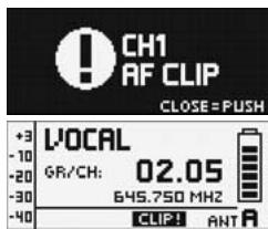
- AF CLIP: Audio overload in transmitter A/D converter. The LED ring is lit red and a large warning message displayed for 5 secs. or as long as the fault condition lasts.
A small warning message is displayed in the main window until the warning is confirmed.
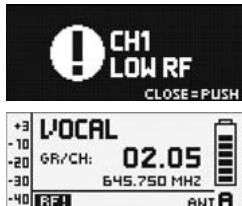
- RF LOW: The field strength of the received RF signal is too low, the receiver's audio output is muted to prevent unwanted noise. The LED ring is lit red and a large warning message displayed for 5 secs. or as long as the fault condition lasts. A small warning message is displayed in the main window until the warning is confirmed.
- ANT ERROR: The same antenna has been active for more than one minute. The LED ring is lit red and a large warning message displayed for 5 secs. or as long as the fault condition lasts.
A small warning message is displayed in the main window until the warning is confirmed.
- INTERFERE: Signal interference from other wireless systems, TV, radio, CB radios, or defective electrical appliances or installations has been detected.
Warning messages in order of priority:
- ENCRYPTION: The Encryption scheme has not been set properly.
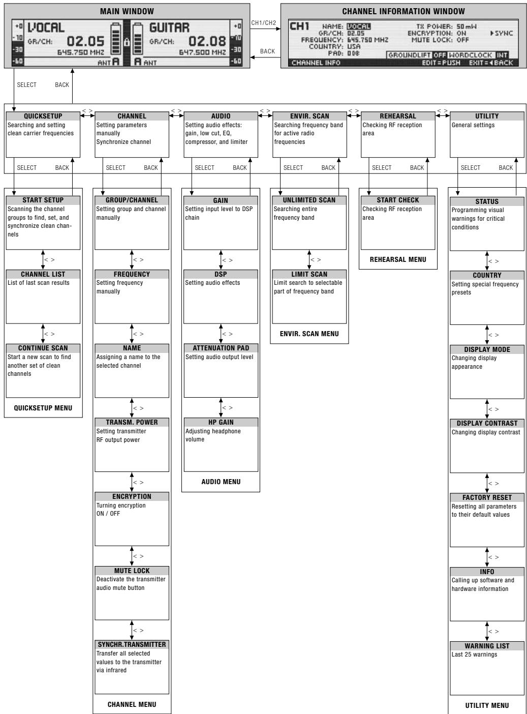
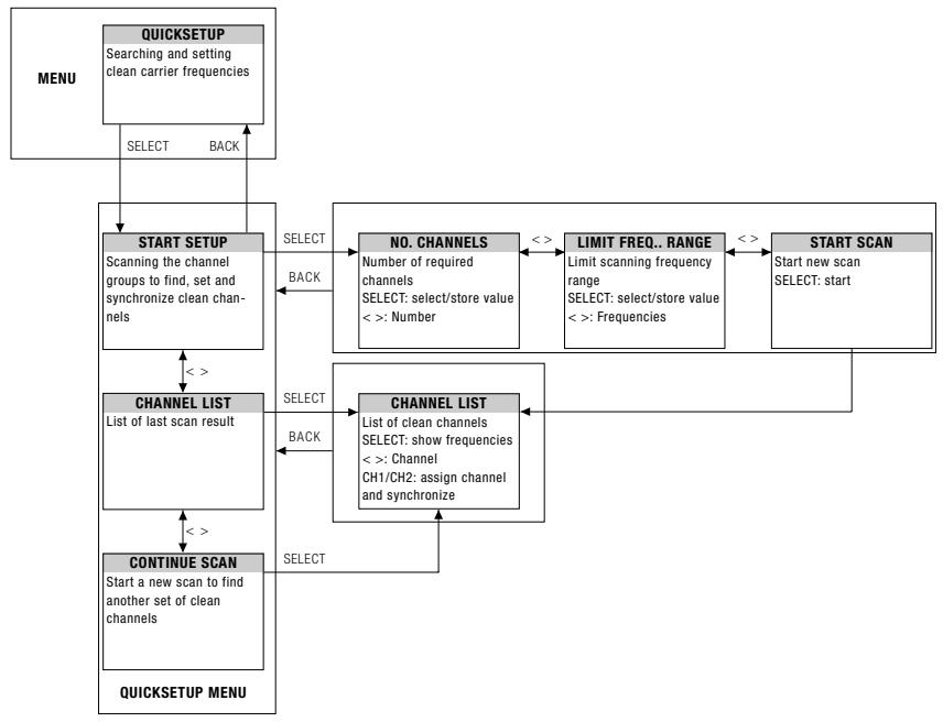
QUICK SETUP
CHANNEL
AUDIO
ENVIR. SCAN
REHEARSAL
UTILITY
Standard Startup
Press ON/OFF button.
Preset Mode
Frequency Mode
Silent Mode Startup
Press ON/OFF and MUTE buttons.
INFO MENU
Silent Mode
9 Function Description
QUICK SETUP
The DSR 700 has been designed for use in large multi-channel systems. To find intermodulation-free and clean carrier frequencies quickly and easily, we recommend using the QUICK SETUP function to find all required channels.
- To start QUICK SETUP, select the START SETUP menu, set the required number of channels as well as the required frequency ranges and start scanning. The scan procedure can take up to one minute. The CHANNEL LIST shows you clean channels in a user-friendly list.
- To assign and synchronize a clean channel to the receiver you can use the channel button.
- Use the CONTINUE SCAN sub-menu to search for other frequencies.
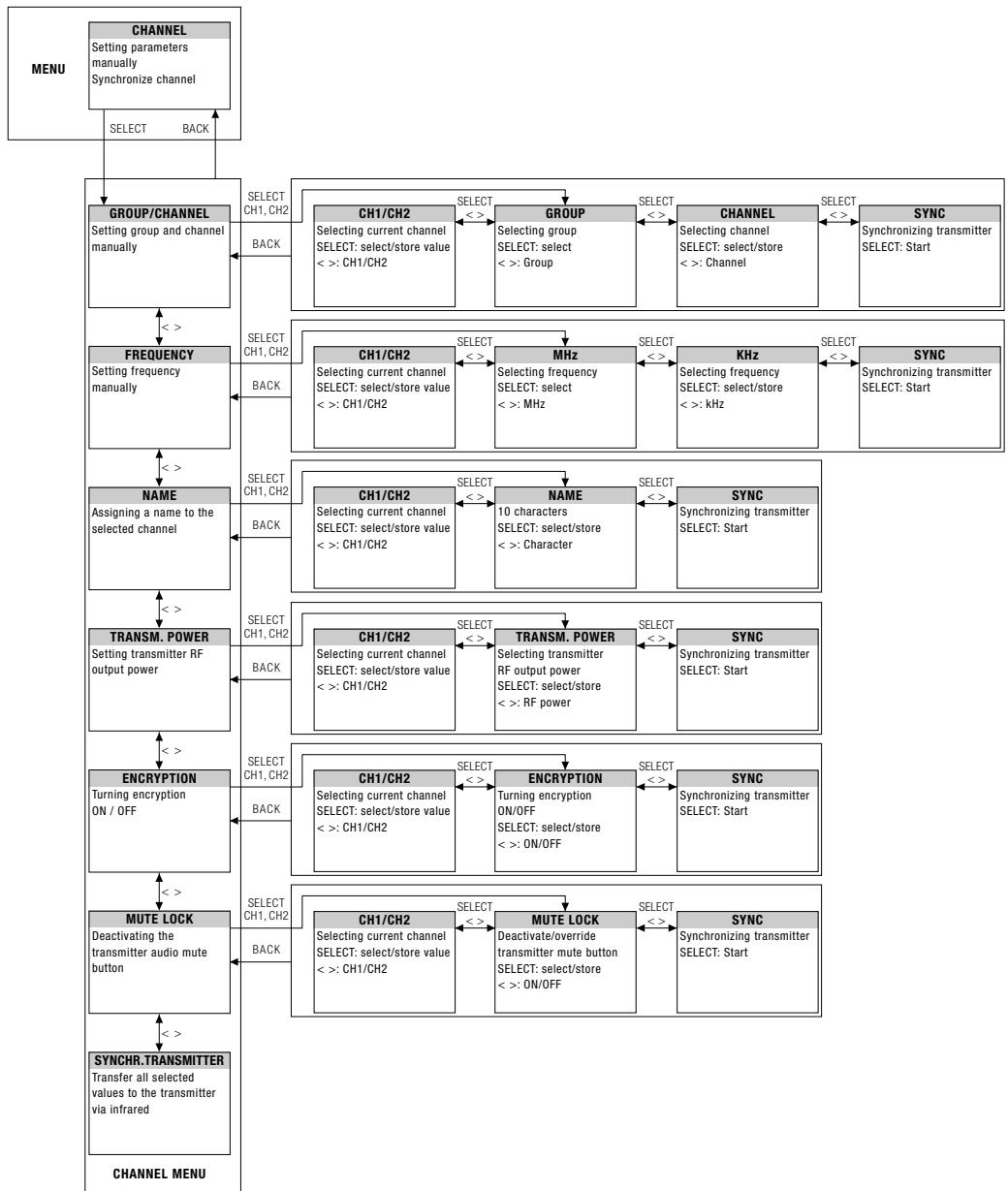
CHANNEL Menu
All channel-specific parameters such as GROUP/CHANNEL, FREQUENCY, NAME, TRANSMISSION POWER, ENCRYPTION and MUTE LOCK can be set and adjusted manually.
GROUP / CHANNEL
The DSR 700 receiver provides frequency groups with specially calculated frequencies. In the GROUP/CHANNEL menu you can set and synchronize a channel (frequency) manually.
Important!
- Make certain that all selected channels are from the same Group within the same Preset. To find clean channels we recommend using the QUICK SETUP function.
FREQUENCY
The FREQUENCY sub-menu allows frequency adjustments in 25-kHz increments.
NAME
You can enter any name (the name of a performer or instrument, etc) for each channel.
TRANSM. POWER
The TRANSM POWER sub-menu lets you adjust the RF output power of the synchronized transmitter.
ENCRYPTION For details, visit www.akg.com.
If you turn on the encryption function, the receiver will calculate a unique key every time that you synchronize the transmitter. The receiver uploads the key during the infrared synchronization process. You cannot read out the encryption key and it is not possible to set two transmitters to the same key.
Note:
- If you use a backup transmitter you must turn off the signal encryption function.
MUTE LOCK
MUTE LOCK deactivates the mute button on the transmitter. The user of the synchronized transmitter cannot mute the audio signal locally.
SYNCHR. TRANSMITTER
During the infrared synchronization process the receiver overwrites all previously selected transmitter settings (Group/Channel, frequency, name, transmission power, encryption key, and mute lock).
- To program the transmitter to the settings you selected on the receiver, start the transmitter synchronization from the receiver menu and point the infrared sensor (4) on the transmitter at the infrared emitter (8) on the receiver from a distance of 4 inches/10 cm max.
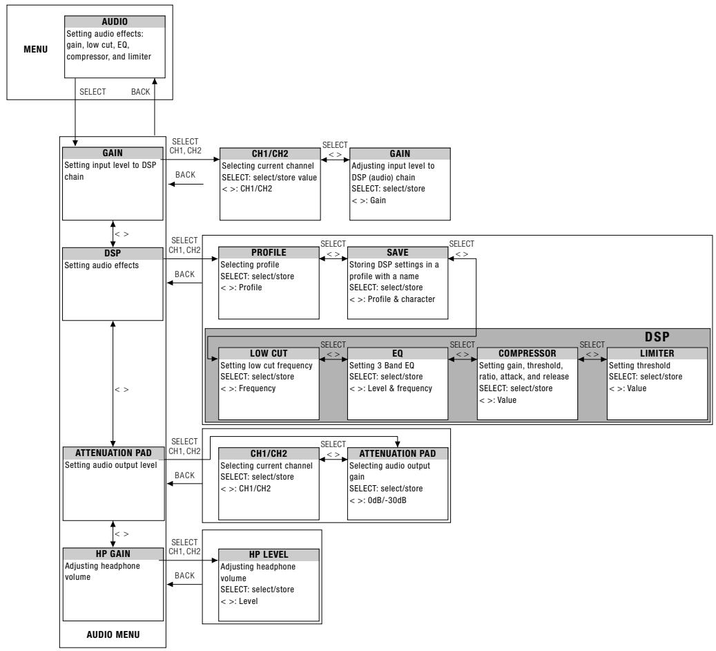
GAIN allows you to set the the input level to the DSP audio processing section.
The built-in digital signal processor with standard processing functions allows you to control your DSP audio signal directly from the receiver. The following dynamics processors are available:
Low cut (frequency)
3-band Equalizer (low gain, mid gain, mid frequency, high gain)
- dbx® Compressor (threshold, ratio, gain, attack and release times)
- dbx® Limiter (threshold)
All settings can be stored together with a freely selectable name in one of nine DSP Profiles.
- Profile changes apply to both channels. All settings previously stored in a Profile will be overwritten.

DSP Profiles -
Factory Default Settings
| LOW CUT | EQ | COMPRESSOR | LIMITER | ||||||||||||
| No. | Profile | Name | Application | Freq. [Hz] | Low dB | Mid dB | MidFreq [kHz] | High [dB] | Thresh-old [dB] | Ratio [dB] | Gain [kHz] | Attack [ms] | Release [ms] | Threshold [dB] | |
| 1 | Presenter | Handheld | Present HT | Inexperienced users, PowerPoint, places of worship, presenters | 77 | 0 | 0 | 1.0 | 3.0 | -30 | 2.1:1 | 3 | 1 | 71 | 0 |
| 2 | Head-worn | Present PT | 40 | OFF | -25 | 1.5:1 | 5 | 6 | 207 | ||||||
| 3 | Music | Handheld | Music HT | Experts, vocalists, rock bands, Karaoke, musical | 40 | OFF | OFF | 9 | |||||||
| 4 | Head-worn | Music PT | |||||||||||||
| 5 | Instrument | Instrument microphone w/bodypack | Instru PT | Beginners and experts, trumpet, tuba, drums | OFF | OFF | OFF | 9 | |||||||
| 6 | Guitar w/bodypack | Guitar PT | EI. guitar, bass guitar, ac-tive acoustic guitar | ||||||||||||
| 7 - 9 | i | User | User 1 - 3 | - | |||||||||||
The DSP button provides a bypass function for LOW CUT, EQ, COMPRESSOR and LIMITER for each DSP Button channel separately.
Matches the receiver's BALANCED output level to the input gain of the connected equipment. If you are using a MIC input on your mixer, the 0 dB level might overload the input. In that case, set the receiver's ATTENUATION PAD to -30 dB to reduce the output level.
The UNBALANCED line output level is not adjustable.
ATTENUATION PAD
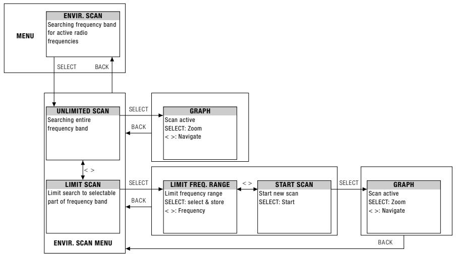
The Environment Scan function turns the receiver into a spectrum analyzer. UNLIMITED SCAN automatically searches the receiver's entire frequency band ± 6 MHz for active radio frequencies. LIMIT SCAN scans only part of the receiver's frequency range. During the search, the audio output is muted and the display shows a frequency graph.
- You can navigate (CW, CCW) and zoom (push) through the graph using the SELECT control.
REHEARSAL - Sound Check
The Rehearsal Scan function converts the receiver to an RF recorder to check the transmitter RF level in your reception area. Maximum recording time is four minutes.
- Start this function and walk around the desired coverage area with the synchronized transmitter. The graphic display indicates the received signal level as it varies over time.
- To mark some positions, you can use the transmitter MUTE button to set markers on the receiver display.
- You can navigate (CW, CCW) and zoom (push) through the graph using the SELECT control.
- The received signal level should never drop below -85 dBm. You can optimize signal reception by changing the position of the connected antennas.
UTILITY Menu STATUS
The STATUS sub-menu lets you activate a visual warning that alerts you of selected critical system conditions. If one of the selected conditions occurs, the LED ring around the SELECT control will change from green to red and a warning message will appear on the display that describes the problem condition. The warning messages appear in the order of priority.
The LED ring is lit red and a large warning message displayed for 5 secs or as long as the fault condition lasts.
A small warning message is displayed until the warning is confirmed.
The selected warning functions are active in LOCK and ACTIVE modes.
- To delete a warning message from the display, press the SELECT control briefly.
Status indications in order of priority:
LOW BATT: The transmitter's remaining battery capacity is low. A large warning message is displayed permanently and the LED ring is lit red.
AF CLIP: Audio overload in transmitter A/D converter. The LED ring is lit red and a large warning message displayed for 5 secs. or as long as the fault condition lasts.
A small warning message is displayed in the main window until the warning is confirmed.
- Reduce the audio input level.
RF LOW: The field strength of the received RF signal is so low that the receiver's audio output is muted to prevent unwanted noise. The LED ring is lit red and a large warning message displayed for 5 secs. or as long as the fault condition lasts.
A small warning message is displayed in the main window until the warning is confirmed.
ANT ERROR: The same antenna has been active for at least one minute. The LED ring is lit red and a large warning message displayed for 5 secs.
A small warning message is displayed in the main window until the warning is confirmed.
- Check if an antenna cable is broken or incorrectly connected.
When you turn the receiver on for the first time, the receiver will ask you to select a country.
- From the UTILITY - COUNTRY menu, you should normally select SD (Standard), EU (EUROPE), or US (USA).
- For some specific countries, you may have to choose one of the internally-stored frequency presets.
- For all other countries, use the SD setting.
This menu lets you change the display appearance. You can choose from four different displays: DISPLAY MODE
MAIN
GROUP/CHANNEL
FREQUENCY

NAME
The DISPLAY CONTRAST sub-menu allows you to adjust the contrast of the display for use in varying displayContrast lighting conditions.
The FACTORY RESET sub-menu allows you to reset all parameters to their default values.
FACTORY RESET
The INFO sub-menu lets you call up software information about your receiver and the transmitter synchronized to it.
INFO
WARNING LIST stores the last 25 warnings.
WARNING LIST
10 Cleaning
DMS 700
- Use a soft cloth moistened with water to clean the surfaces of the equipment.
| Problem | Possible Cause / Remedy |
| No sound. | • Interference from other wireless systems, TV, radio, CB radios, defective elec-trical appliances or wiring.• Transmitter is tuned to different frequency than receiver.• Transmitter is "OFF" or transmitter MUTE switch set to "MUTE".• Power cord is not connected to receiver and/or power outlet.• Receiver is OFF.• Receiver is not connected to sound system.• Microphone or instrument is not connected to bodypack transmitter.• Transmitter batteries are not inserted properly.• Transmitter batteries are dead.• Transmitter is too far away from receiver.• Obstructions between transmitter and receiver are blocking the signal.• Receiver is invisible from transmitter location.• Receiver too close to metal objects.• Software versions of the transmitter and receiver do not match. |
| Distortion. | • Gain settings are too low or too high.• DSP functions are not set properly. |
| Momentary loss of sound ("dropouts") at some points within performance area. | • Relocate receiver or re-orient the antennas. If dead spots persist, mark and avoid them.• Transmitter is too far away from receiver. |
| Status/Error/Warning Message | Problem / Remedy |
| RF LOW | ·The field strength of the received RF signal is so low that the receiver audio output is muted to prevent unwanted noise. -Re-locate receiver or use remote antennas. |
| AF CLIP | ·Audio overload in transmitter A/D converter. -Reduce audio input level. |
| ANT ERROR | ·The same antenna has been active for at least two minutes. -Check if antenna cable(s) is/are broken or incorrectly connected. |
| LOW BATT | ·Transmitter battery capacity is low. -Insert new batteries. |
| SYSTEM ERROR | ·Internal error. -Switch power to receiver OFF and back ON after about 10 seconds. If the problem persists, contact your AKG Service Center. |
| RF ERROR, PLL ERROR | ·Receiver cannot lock on to the selected frequency. -Push SELECT briefly to confirm error and select a different frequency. -If the problem persists, contact your AKG Service Center. |
| UPDATE FIRMWARE | ·System is ready for software update. -Switch power to receiver OFF and back ON after about 10 seconds. -If the problem persists, contact your AKG Service Center. |
| INTERFERE ERROR | ·Transmitter signal is being “jammed” by other wireless systems, TV, radio, CB radios, or defective electrical appliances or installations. -Change frequency or switch off interfering device. |
| ENCRYPTION! | ·Encryption is not set properly. -Synchronize transmitter. -Interference from other DMS 700 transmitter. |
11 Troubleshooting
| SYNC Messages | Problem / Remedy |
| WRONG DEVICE | • Transmitter frequency band does not match the receiver's frequency band. |
| ERROR DEVICE | • Error in transmitter ID data. - If the problem occurs frequently, contact your AKG Service Center. |
| TIMEOUT | • No infrared data detected. |
DMS 700 Digital Microphone System
| Carrier frequency range | Band 1: 548.1 to 697.9 MHz Band 2: 710.1 to 864.9 MHz |
| Switching bandwidth | ≤ 155 MHz (depending on local regulations) |
| Audio bandwidth | 25 Hz to 20 kHz (±3 dB) |
| T.H.D. | ≤ 0.05 % |
| Signal/noise ratio (A-weighted) | Analog: XLR balanced, typ. 115 dB(A) Digital: AES-EBU, typ. 120 dB(A) |
| Audio sampling rate | 24 Bit / 44.1 kHz |
| Modulation | Digital |
| Bit rate | < 200 kbps |
| Compression | AKG premium audio compression technology |
| Latency | 4 msecs. |
| Encryption | YES |
| Temperature range | 14 to 131°F / -10 to 55°C |
| Carrier frequency range | Band 1: 548.1 to 697.9 MHz Band 2: 710.1 to 864.9 MHz |
| Switching Bandwidth | ≤ 155 MHz (country dependent) |
| Channels | 2 (Dual Receiver) |
| Sensitivity | 10 dBμV / -97 dBm |
| Receiver type | Super heterodyne |
| Diversity system | Digital true diversity |
| Antenna inputs | 2 x 50-ohm BNC female connector |
| Audio outputs | 2 x analog: balanced XLR 2 x analog: unbalanced ¼" jack 1 x digital: AES-EBU XLR (48 kHz) w/ BNC Wordclock IN |
| Audio output level | XLR balanced: +12 dBu (max.) |
| Low cut | 0 to 300 Hz |
| Equalizer | 3-band (parameters: low gain, mid gain, mid frequency, high gain) |
| Compressor | dbx® (parameters: gain, threshold, ratio, attack, release) |
| Limiter | dbx® (parameter: threshold) |
| Transmitter battery meter | 7-segment bargraph |
| PC interface | Ethernet via HUB 4000 Q, HiQnet System Architect software |
| Power supply | 90 to 240 VAC, 50 to 60 Hz, 0.4 A |
| Dimensions | Standard 1U rack-mount case 18.9(W) x 1.7(H) x 7.87(D) in. / 480(W) x 43(H) x 200(D) mm |
| Net weight | 5.1 lbs. / 2.3 kg |
| Carrier frequency range | Band 1: 548.1 to 697.9 MHz Band 2: 710.1 to 864.9 MHz |
| Switching bandwidth | ≤ 155 MHz (country dependent) |
| RF output power | 10, 20, 30, 50 mW (ERP max.), software-adjustable (depending on local regulations) |
| Spurious | ≤ -70 dBc |
| Antenna | ¼- wave antenna |
| Audio input | TB3M / 3-pin mini XLR socket (2.5 Vrms max.) |
| Battery life | ≥ 8 hours (2 x 1.5-V LR6 AA size batteries) ≥ 8 hours (2 x 1.2-V AA size NiMH >2100 mAh recharge able batteries) |
| Dimensions | 3.3(W) x 2.5(H) x 0.86(D) in. 83.5(W) x 64.1(H) x 22(D) mm |
| Net weight | 2.9 oz / 82 g without batteries |
| Switching Bandwidth | ≤ 155 MHz (country-dependent) |
| RF output power | 10, 20, 30, 50 mW (ERP max.), software-adjustable (depending on local regulations) |
| Spurious | ≤ -70 dBc |
| Antenna | Built-In helical antenna |
| Microphone element | DHT 700 D5: dynamic microphone (supercardioid) DHT 700 C5: condenser microphone (cardioid) |
| Max. SPL | DHT 700 D5: ≤ 140 dB SPL DHT 700 C5: ≤ 140 dB SPL |
| Battery life | ≥ 8 hours (2 x 1.5-V LR6 AA batteries) ≥ 8 hours (2 x 1.2-V AA size NiMH >2100 mAh recharge able batteries) |
| Dimensions | 2(dia.) × 9.1(L) in. / 52(dia.) × 231(L) mm |
| Net weight | 11.8 oz / 336 g |
This product conforms to the standards listed in the Declaration of Conformity. To order a free copy of the Declaration of Conformity, visit http://www.akg.com or contact sales@akg.com.
Vielen Dank,
Ground Lift (16, 19) 37
Ground Lift (16, 19)
Ground Lift (16, 19) 65
Ground Lift (16, 19)
Ventana principal 95
A工程技术 of the SINO-TECHNICAL SOLUTIONS (TAP) is a project that aims to improve the performance of the SINO-TECHNICAL SOLUTIONS (TAP) in order to achieve the goal of improving the performance of the SINO-TECHNICAL SOLUTIONS (TAP). The main aim of this project is to develop and test a new technology for the operation of the SINO-TECHNICAL SOLUTIONS (TAP) in order to improve the performance of the SINO-TECHNICAL SOLUTIONS (TAP).
For other products and distributors worldwide visit www.akg.com


ROHS OK
H A Harman International Company
Technische Änderungen vorhabten. Specifications subject to change without notice. Ces caractéristiques sont susceptibles de modifications. Ci riserviamo il diritto di effettare modifiche tecniche. Nos reservamos el dato de introducirmericanas. Especificações sujeitas a mudanças sem uso prévio.
Printed in Austria
03/09/9100 U 12810

- Symbols Used
- Important Note!
- FCC Statement
- Safety and Environment
- Safety
- Environment
- DSR 700
- Operating Notes
- SELECT Control (5)
- LOCK Mode:
- SETUP Mode:
- CH1/CH2 Buttons (10/12)
- BACK Button (4)
- DSP Button (2)
- Checking the Audio Signal-Headphones CH1 and CH2 Buttons (6)
- Antenna Indication
- Status & Warning Messages
- Standard Startup
- Preset Mode
- Frequency Mode
- Silent Mode Startup
- Silent Mode
- Function Description
- QUICK SETUP
- CHANNEL Menu
- GROUP / CHANNEL
- Important!
- FREQUENCY
- NAME
- TRANSM. POWER
- ENCRYPTION For details, visit www.akg.com.
- Note:
- MUTE LOCK
- SYNCHR. TRANSMITTER
- REHEARSAL - Sound Check
- UTILITY Menu STATUS
- Cleaning
- Troubleshooting
- DMS 700 Digital Microphone System
- Vielen Dank,
- H A Harman International Company
Brand : AKG
Model : DMS 700
Category : Wireless Microphone System