
VT7 - Motherboard ABIT - Free user manual and instructions
Find the device manual for free VT7 ABIT in PDF.

| Product Type | Desktop Motherboard |
| Form Factor | ATX |
| Processor Socket | Socket 478 |
| Compatible Processors | Intel Pentium 4 |
| Memory Support | DIMM DDR, 2 slots |
| Power Connector | ATX 12V (20+4 pins) |
| Internal Connectors | IDE, FDD, SATA (depending on model) |
| Expansion Slots | AGP, PCI |
| Rear I/O Connectors | PS/2, USB, parallel, serial, audio |
| Dimensions (L x W) | 305 x 244 mm |
| Weight | Approximately 500 g |
| Required Power Supply | ATX power supply with 12V connector |
| Main Features | Pentium 4 support, configurable BIOS, thermal management |
| Maintenance and Cleaning | Discharge static electricity before handling; use a dry cloth |
| Safety | Avoid contact of metal screws with the PCB; use standoffs |
| Spare Parts and Repairability | Heatsink, fan, RAM modules, cables; repairable with compatible parts |
| General Information | Brand ABIT, model VT7, manual available in PDF |
Frequently Asked Questions - VT7 ABIT
User questions about VT7 ABIT
0 question about this device. Answer the ones you know or ask your own.
Ask a new question about this device
Download the instructions for your Motherboard in PDF format for free! Find your manual VT7 - ABIT and take your electronic device back in hand. On this page are published all the documents necessary for the use of your device. VT7 by ABIT.
USER MANUAL VT7 ABIT
Socket 478 System Board User's Manual
Copyright and Warranty Notice
The information in this document is subject to change without notice and does not represent a commitment on part of the vendor, who assumes no liability or responsibility for any errors that may appear in this manual.
No warranty or representation, either expressed or implied, is made with respect to the quality, accuracy or fitness for any particular part of this document. In no event shall the manufacturer be liable for direct, indirect, special, incidental or consequential damages arising from any defect or error in this manual or product.
Product names appearing in this manual are for identification purpose only and trademarks and product names or brand names appearing in this document are the property of their respective owners.
This document contains materials protected under International Copyright Laws. All rights reserved. No part of this manual may be reproduced, transmitted or transcribed without the expressed written permission of the manufacturer and authors of this manual.
If you do not properly set the motherboard settings, causing the motherboard to malfunction or fail, we cannot guarantee any responsibility.
Table Of Contents
VT7快速安装指引 2
VT7のクイックインストーリド 4
VT7 Schnellinstallationsanleitung 6
VT7 Guide d'Installation Rapide 8
KpaTkoe pyKOBoCTBO IIO yCTaHOBKe VT7. 10
Guida all's installatione veloce Scheda madre VT7 12
Chapter 1. Introduction 1-1
1-1. Features & Specifications 1-1
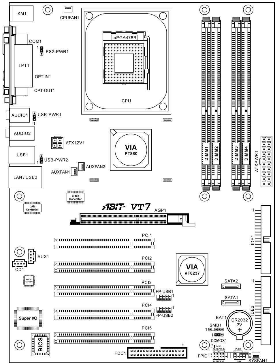
1-2. Layout Diagram 1-3
Chapter 2. Hardware Setup 2-1
2-1. Install The Motherboard.. 2-1
2-2. Install Pentium® 4 CPU and Heatsink Supporting-Base. 2-2
2-3. Install System Memory 2-3
2-4. Connectors, Headers and Switches 2-4
(1).ATX Power Input Connectors. 2-4
(2). FAN Connectors. 2-5
(3). CMOS Memory Clearing Header 2-6
(4). Wake-up Header 2-7
(5). Front Panel Switches & Indicators Headers 2-8
(6). Additional USB Port Headers 2-9
(7). Internal Audio Connectors 2-10
(8). Accelerated Graphics Port Slot. 2-10
(9). Floppy Disk Drive Connector. 2-11
(10). IDE Connectors 2-12
(11). Serial ATA Connectors. 2-13
(12). System Management Bus Headers. 2-13
(13). Status Indicator 2-14
(14). Back Panel Connectors 2-15
Chapter 3. BIOS Setup 3-1
3-1. SoftMenu Setup.. 3-2
3-2. Standard CMOS Features 3-4
3-3. Advanced BIOS Features.. 3-7
3-4. Advanced Chipset Features 3-10
3-5. Integrated Peripherals 3-14
3-6. Power Management Setup 3-18
3-7. PnP/PCI Configurations 3-21
3-8. PC Health Status 3-23
3-9. Load Fail-Safe Defaults 3-25
3-10. Load Optimized Defaults.. 3-25
3-11. Set Password 3-25
3-12. Save & Exit Setup 3-25
3-13. Exit Without Saving 3-25
Appendix A. Install VIA 4-in-1 Driver
Appendix B. Install Audio Driver.. 2
Appendix C. Install LAN Driver..
Appendix D. Install VIA USB 2.0 Driver
Appendix E. Install Serial ATA RAID Driver. E-1
Appendix F. ABIT EQ (The Hardware Doctor Utility)
Appendix G. FlashMenu (BIOS Update Utility) 2
Appendix H. Troubleshooting (Need Assistance?)....H-1
Appendix I. How to Get Technical Support. 1-1

VT7 快速安装指引
- HaJIHTe Ha cHCTeMHoI IJIaTe 478-BlIBOJHOI pa3bEm TIIa ZIF. 3aKpeINTe OCHOBaHHe paHaTopa Ha cHCTeMHoI IJIaTe.
BHHMaHHe: YcTaHaBJIHbAa IIaTy B KOpIYc, pa3pa6oTaAHbI cIIeuaJIbHO IJIa Pentium 4, o6paTHTe BHHMaHHe Ha yJke yCTaHOBJeHNbI KpeIeK (MeTaJIInueCKHe cToKN, 3aJKNMbI). Y6eINTEcb, YTO yCTaHOBJeHNbI KpeIeK He Kacaetcsc nCTeMHoI IIaTbI HII ee BBIOOB.
- OTTHHTe pbyar fHKcaHHI Ipoeeccopa B CTOPHY HIOHNHMTe ero Ha 90 rpaYcoB BBepx. PaHOJOKINB Ipoeeccop COOTBETCTBYIOHM O6pa3OM, BCTaBBte erO B pa3bEm. He IIpaIaIaIte H3JIHHHX ycJIiH, YTO6bl BCTaBHb Ipoeeccop. Ipooeccop JeTKO yTaHaBJIHBAeTcE, cJIH Bbl IIpaBIJbHO COBMecTHII erO c pa3bEMOM. YCTaHOHB Ipoeeccop, onyctHtpe pbhar fHKcaHHI Ipoeeccopa Ha MeCTO.
3.Плжнту на поцesscop радатор tak,чTo6bI OH ПлJOHOCTBIO HAkpBaJI поцesscop.
4.ПJOIOKHTe Ha paIHaTOp BeHTHJIaTOp H 1HKKCHpyIOIIH MexaHH3M.Y6eIHITecb, YTO BCE YeTbipe 1HKKcTaOpa BEHTHJIaTOpa H 1HKKCHpyIOIIeIero MexaHH3Ma BOIIIIN B IpeJHa3HaueHHbIe OTBepCTHn H 3aIIeJIKHyJIHcB. - 3aΦHKChpyTe BeHTHJIArTop Ha OCHOBAHn paHaTopa, onyCTHB pyuKaKN, paIOIOKeHHbIe c o6EHx cToPOH ΦHKChpyIOIero mexAHN3Ma.
- BeHTHJIaTOp, ΦHKcHpyUOIIHm MexaHH3M n OCHOBaHHe paJHaTopa JIOJKHb 6bITb HaJeKHO 3aKpeIJIeHb BMeCTe C BeHTHJIaTOpOM.
BHHMaHHe: YcTaHOBHTe COOTBeTCTByIOIIne HaCTOTy H KpaTHOcTB IIHHbI IpoIeccopa.
YcTaHOBKa MaTePnHcKoI IaTbI B KOpNyc
IocJe yctAHOBKn IpoIeesscopa Ha MaTePHNcKyo IJIaTy MOKHO HauHHaTb ycTaHOBKy MaTePHNcKoI IJIaTb B KopIyc. BoJIbIIaJy cAcTb KOpIycOB O6OpYIOBaHa OCHOBaHHem, B KOTOpOM IpoDeJaHbMOHTaXHBe OTBepCTHn, KOtOpBle IO3BOJIaHOT HaIdekHO 3aKpeINITb MaTePHNcKyo IJIaTy H IpEIoTbPaHTb KOpOTKHe 3aMbKaHHa.ДЯ KpeIJIeHHa MaTePHNcKo IJIaTb K OCHOBaHHIO HcIOJIb3yOTcB BHTbI H IPOKJIaIKH.
YcTaHOBKa MoJyJeIiMaHTN
- HaJIHTe Ha cHCTeMHoH IJIaTe pa3bEm JINMOyJIeI IIAMrTH DIMM.
- AkkypaTHO, 3a Два KOHua, BO3bMHTe MODYJIb IIAMyTH, He KaCaaCb KOHTaKTOB.
- CoBmecHTHe BbIeMky B MoIyJIe IaMaTHn C BbICTYIOB Bpa3bEme.
- HaKMHTe Ha MOyJb TaK, YTO6bJI JeIeCTKN BbITaIKHBateJIc o6eHX cTOpOH pa3beMa
aBToMATHUeCKH 3aIeJIKHyIINc H BOIIIN B Ia3bI. He IIpHMeHnTe IIph yctaHOBKe H3JIINIIIIOO cHJy. MoIyJB BXoIHT B pa3bEm TOJIbKO B OJHOM IOJIOKeHHN.
5.ДИЯ H3BJIeueHЯ MOnIyIeI IaMraTH DIMM OdIOHOBpeMeHHo HaKMHTe HaJIeNcTKH BbITaIKHBaTeJIA H bItaIIHTe MoIyJIb.
BHHMaHHe: CtaTHueCkoe 3JIeKTPnueCTBO MOKeT cTaTB IIpNHHO BbIXOa H3 cTPOJ3JIeKTPoHHbIX KOMIIHOHTOB KOMIIbIOTepa. IpeE Haayaiom DaHHo IIpoJeDpybI cHMMITE c ce6a cTaTHueCKH 3apd, KCHyBIIIcB 3a3eMJIeHHOro MTeAJIHHueCKOrO IIpeDMeta.
Pa3bembl, IpeekJIOUaTeJIH n aIaIITepbl
BHyTpH KOpIpyCa KOMIIbHOTepa Heo6xOJHMO paCIOIOJKeHb HeckOJIbKO Ka6eJIe H BHIOK, KOToPbIE Heo6xOJHMO POJIKIOUHTb. O6bYHO 3TN Ka6eJIH IOKJIIOHuaOTcK Pa3bEAM, paCIOIOJKeHHbIM Ha MaTePHNcKoi PJIate. PnH POJIKIOUeHHN IO6OBO Ka6eJIaHeo6xOJHMO o6paIIaTb BHNMaHHe Ha PaCIOIOJKeHHe NepBOrO KOHTAKTa pa3bEma. IJIaOC6bIX IIeJIe MOrYT IOTpe6OBaTbc CNEIHJaJIbHBe aADIaIITpe, HApINMeP, aADIaIETp SCSI, aADIaIETp AGP N.T.. PnH yCTaHOBke aADIaIETpOB B rHe3Ja MaTePHNcKoi PJIaTb 3AkpeINHe IX Ha 3aIDHe N aHEJIc c NMOIIIbO BVHTOB.
3a 6oJIee IIOIpo6Hoi HnΦopMaIHeN O6paIIaJItecB K IIOJIHOmy pyKOBOICTBy IIOJIb3OBaTeJIa.
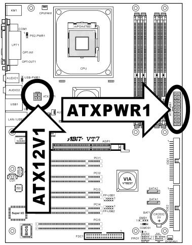
IoiKJIIOUeHHe Ka6eJeI INTahHn K pa3bEmam ATX12V
O6paTHHe BHHMaHHe, pa3bEm 6Ioka IIITaHnH ATX He06xOIMo BcTaBHTb B pa3bEm ATX12V Do yInopa, TTO6bI o6ecneuHTb HaJeKHOe coeHNHeHHe.
Hactpoika BIOS
1-1. Features & Specifications
1. CPU
Supports Intel Pentium 4 Socket 478 processor with 800MHz 533MHz and 400MHz (for Northwood only) System Data Bus
Supports Intel Hyper-Threading Technology
2. Chipset
VIA PT880 + VT8237
Supports Hi-Speed Universal Serial Bus (USB 2.0)
3. Memory
Four 184-pin DIMM sockets (Un-buffered, Non-ECC DIMM)
Supports Dual DDR 400/333/266 (Max. 4GB)
4. AGP
- Accelerated Graphics Port connector supports AGP 8X/4X Interface (0.8V/1.5V)
5. Serial ATA 150 RAID
- Onchip 2 channels of Serial ATA 150MB/s data transfer rate with RAID 0/RAID 1function via South Bridge
6. Audio
Onboard 6-Channel AC 97 CODEC
Professional digital audio interface supports S/PDIF In/Out
7. LAN
Onboard 10/100M LAN Controller
10/100Mb operation support ACPI & Wake on LAN
8. System BIOS
- SoftMenu™ Technology to set CPU parameters
Supports Advanced Configuration Power Interface (ACPI)
9. Internal I/O Connectors
1x AGP slot
- 5x PCI slots
1x floppy port supports up to 2.88MB
2x Ultra ATA 133/100/66/33 connectors
2x Serial ATA 150 connectors
- 2x USB headers
1x CD-IN, 1x AUX-IN header
10. Back Panel I/O
- 1x PS/2 keyboard, 1x PS/2 mouse
- 1x Serial port connector, 1x Parallel port connector
1x S/PDIF In connector
1x S/PDIF Out connector
1x AUDIO1 connector (Rear-Left / Rear-Right, Center/Subwoofer)
1x AUDIO02 connector (Mic-In, Line-In, Front-Left/Right) - 2x USB connectors
- 2x USB connectors, 1x RJ-45 LAN connector
11. ABIT Engineered
- ABIT SoftMenu™ Technology
ABIT TweakGuardTM - ABIT CPU ThermalGuard™
ABIT FAN EQTM
ABIT FAN SecureTM - ABIT Flash Menu
12. Miscellaneous
ATX form factor (305× 225mm)
- Hardware Monitoring - Including Fan speed, Voltages, CPU and System temperature
- Specifications and information contained herein are subject to change without notice.
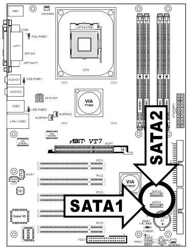
1-2. Layout Diagram

Chapter 2. Hardware Setup
Before the Installation: Turn off the power supply switch (fully turn off the +5V standby power), or disconnect the power cord before installing or unplugging any connectors or add-on cards. Failing to do so may cause the motherboard components or add-on cards to malfunction or damaged.
2-1. Install The Motherboard
Most computer chassis have a base with many mounting holes to allow motherboard to be securely attached on and at the same time, prevented from short circuits. There are two ways to attach the motherboard to the chassis base:
- use with studs
- or use with spacers
In principle, the best way to attach the board is to use with studs. Only if you are unable to do this should you attach the board with spacers. Line up the holes on the board with the mounting holes on the chassis. If the holes line up and there are screw holes, you can attach the board with studs. If the holes line up and there are only slots, you can only attach with spacers. Take the tip of the spacers and insert them into the slots. After doing this to all the slots, you can slide the board
into position aligned with slots. After the board has been positioned, check to make sure everything is OK before putting the chassis back on.

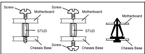
ATTENTION: To prevent shorting the PCB circuit, please REMOVE the metal studs or spacers if they are already fastened on the chassis base and are without mounting-holes on the motherboard to align with.
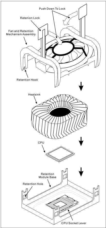
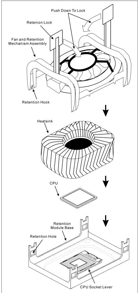
2-2. Install Pentium® 4 CPU and Heatsink Supporting-Base
This motherboard provides a ZIF (Zero Insertion Force) Socket 478 to install Intel Pentium CPU. The CPU you bought should have a kit of heatsink and cooling fan along with. If that's not the case, buy one specially designed for Pentium 4 Socket 478.
- Locate the 478-pin ZIF socket on the motherboard. Fasten the Retention Module Base onto the motherboard.
ATTENTION: If you are using chassis specially designed for Pentium 4, please pay attention to the location of metal studs or spacers if they are already installed on the chassis. Be careful not let the metal studs or spacers contact the printed circuit wire or parts on the PCB.
- Pull the CPU socket lever sideways away from the socket and then upwards to 90 degree. Insert the CPU with the correct orientation. Do not use extra force to insert CPU; it only fits in one orientation. Close down the socket lever while holding down the CPU.
- Put the heatsink faces down onto the CPU until it completely covers the CPU.
- Put the Fan and Retention Mechanism Assembly onto the heatsink. Make sure all the four Retention Locks at each side of the Fan and Retention Mechanism Assembly snap into the Retention Holes.
- Push down the Retention Lock at both sides of the Fan and Retention Mechanism Assembly to lock up together with the Retention Module Base.
- The Fan and Retention Mechanism Assembly and Retention Module Base should now firmly lock up with each other with the heatsin
ATTENTION: Do not forget to set the correct bus frequency and multiple for your processor.
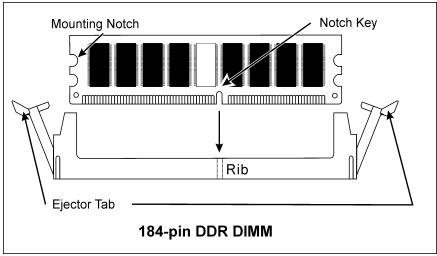
2-3. Install System Memory
This motherboard provides four 184-pin DDR DIMM slots for Single/Dual Channel DDR 400/333/266 memory modules with memory expansion size up to 4GB.
To reach the performance of Dual Channel DDR, the following rules must be obeyed:
- When installing TWO DIMM modules: Install DIMM modules of the same type and size for slots [DIMM1] + [DIMM3] or slots [DIMM2] + [DIMM4].
- When installing FOUR DIMM modules: Install DIMM modules of the same type and size for slots [DIMM1] + [DIMM3], and slots [DIMM2] + [DIMM4].
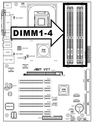
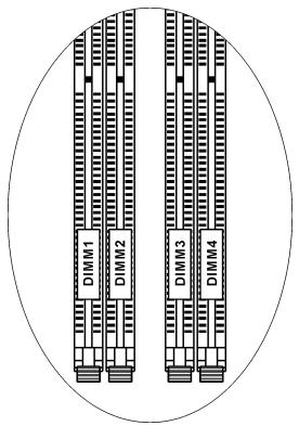
Table 2-1. Valid Memory Configurations
| Bank | Memory Module | Total Memory |
| Bank 0,1 (DIMM1) | 128, 256, 512MB, 1GB | 128MB ~ 1GB |
| Bank 2,3 (DIMM2) | 128, 256, 512MB, 1GB | 128MB ~ 1GB |
| Bank 4,5 (DIMM3) | 128, 256, 512MB, 1GB | 128MB ~ 1GB |
| Bank 6,7 (DIMM4) | 128, 256, 512MB, 1GB | 128MB ~ 1GB |
| Total System Memory | 128MB ~ 4GB | |
NOTE: No hardware or BIOS setup required after adding or removing memory modules.
2-4. Connectors, Headers and Switches
Here we will show you all of the connectors, headers and switches, and how to connect them. Please read the entire section for necessary information before attempting to finish all the hardware installation inside the computer chassis. A complete enlarged layout diagram is shown in Chapter 1 for all the position of connectors and headers on the board that you may refer to.
WARNING: Always power off the computer and unplug the AC power cord before adding or removing any peripheral or component. Failing to so may cause severe damage to your motherboard and/or peripherals. Plug in the AC power cord only after you have carefully checked everything.
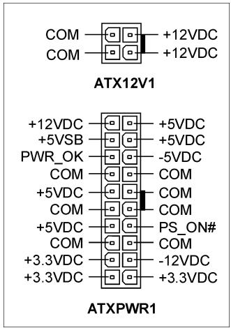
(1).ATX Power Input Connectors
This motherboard provides two power connectors to connect to an ATX12V power supply with 300W, 20A + 5VDC , and 720mA + 5VSB capacity at least.
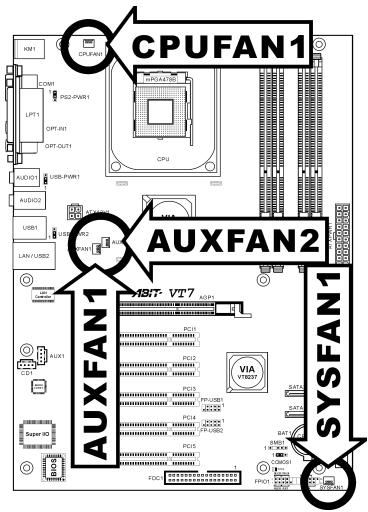
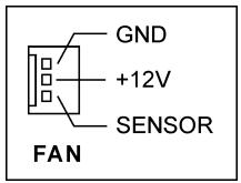
(2). FAN Connectors
These 3-pin connectors each provide power to the cooling fans installed in your system.
The CPU must be kept cool by using a powerful fan with heatsink. The system is capable of monitoring the speed of the CPU fan.
- CPUFAN1: CPU Fan
- SYSFAN1: System Fan
- AUXFAN1/AUXFAN2: Auxiliary Fan
WARNING: These fan connectors are not jumpers. DO NOT place jumper caps on these connectors.
(3). CMOS Memory Clearing Header
This header uses a jumper cap to clear the CMOS memory.
Pin 1-2 shorted (default): Normal operation.
Pin 2-3 shorted: Clear CMOS memory.
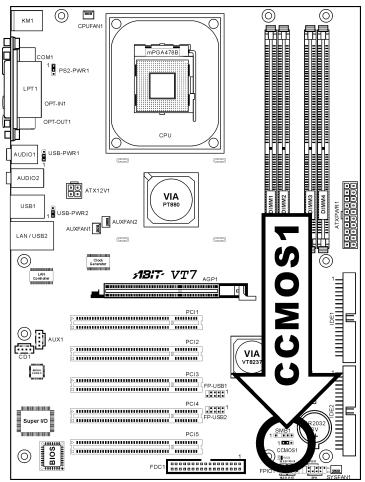
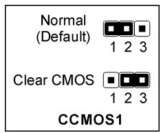
WARNING: Turn the power off first (including the +5V standby power) before clearing the CMOS memory. Failing to do so may cause your system to work abnormally or malfunction.
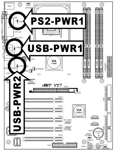
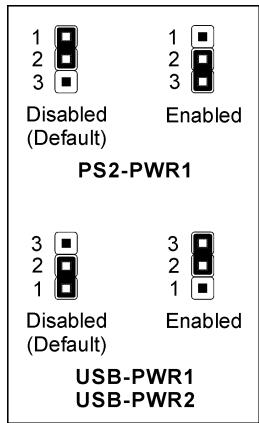
(4). Wake-up Header
These headers use a jumper cap to enable/disable the wake-up function.
PS2-PWR1:
Pin 1-2 shorted (default): Disable wake-up function support at Keyboard/Mouse port.
Pin 2-3 shorted: Enable wake-up function support at Keyboard/Mouse port
USB-PWR1:
Pin 1-2 shorted (default): Disable wake-up function support at USB1 port.
Pin 2-3 shorted: Enable wake-up function support at USB1 port.
USB-PWR2:
Pin 1-2 shorted (default): Disable wake-up function support at USB2 port.
Pin 2-3 shorted: Enable wake-up function support at USB2 port
(5). Front Panel Switches & Indicators Headers
This header is used for connecting switches and LED indicators on the chassis front panel.
Watch the power LED pin position and orientation. The mark "+" align to the pin in the figure below stands for positive polarity for the LED connection. Please pay attention to connect these headers. A wrong orientation will only cause the LED not lighting, but a wrong connection of the switches could cause system malfunction.
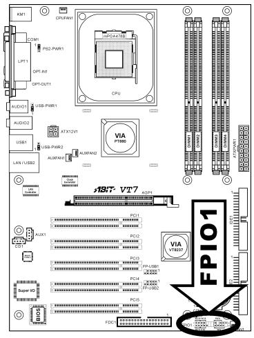
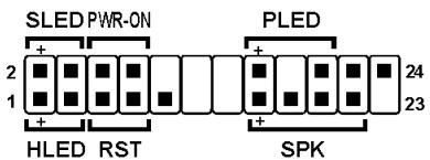
FPI01
- HLED (Pin 1, 3):
Connects to the HDD LED cable of chassis front panel.
RST (Pin 5,7):
Connects to the Reset Switch cable of chassis front panel.
- SPK (Pin 15, 17, 19, 21):
Connects to the System Speaker cable of chassis.
- SLED (Pin 2, 4):
Connects to the Suspend LED cable (if there is one) of chassis front panel.
PWR-ON (Pin 6,8):
Connects to the Power Switch cable of chassis front panel.
- PLED (Pin 16, 18, 20):
Connects to the Power LED cable of chassis front panel.
(6). Additional USB Port Headers
These headers each provide 2 additional USB 2.0 ports connection through an USB cable designed for USB 2.0 specifications.
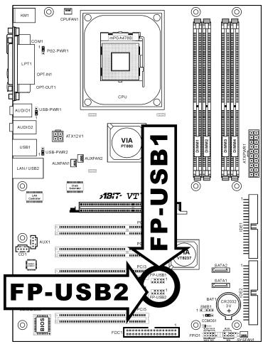
| 7 5 3 1 10 8 6 4 2 FP-USB1 FP-USB2 | Pin | Pin Assignment | Pin | Pin Assignment |
| 1 | VCC | 2 | VCC | |
| 3 | Data0 - | 4 | Data1 - | |
| 5 | Data0 + | 6 | Data1 + | |
| 7 | Ground | 8 | Ground | |
| 9 | NC | 10 | NC |
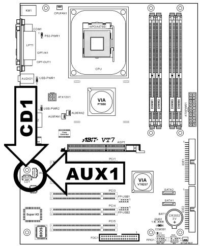
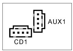
(7). Internal Audio Connectors
These connectors connect to the audio output of internal CD-ROM drive or add-on card.
(8). Accelerated Graphics Port Slot
This slot supports an optional AGP graphics card up to AGP 8X mode. Please refer to our Web site for more information on graphics cards.
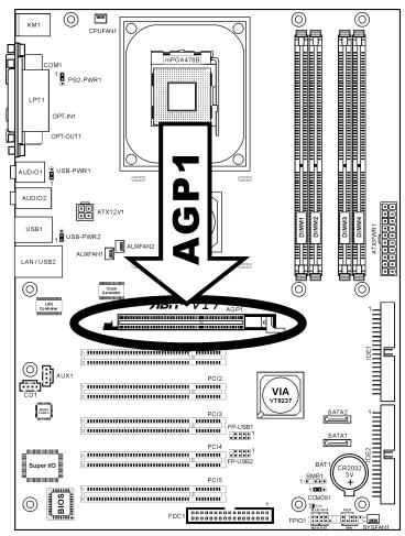
ATTENTION: This motherboard does not support 3.3V AGP cards. Use only 1.5V or 0.8V AGP cards.
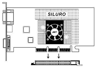
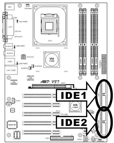
(9). Floppy Disk Drive Connector
This connector supports two standard floppy disk drives via a 34-pin 34-conductor ribbon cable.
Connecting the Floppy Disk Drive Cable:
- Install one end of the ribbon cable into the FDC1 connector. The colored edge of the ribbon cable should be aligned with pin-1 of FDC1 connector.
- Install the other end(s) of ribbon cable into the disk drive connector(s). The colored edge of the ribbon cable should be also aligned with pin-1 of disk drive connector. The endmost connector should be attached to the drive designated as Drive A.
FDC1
1

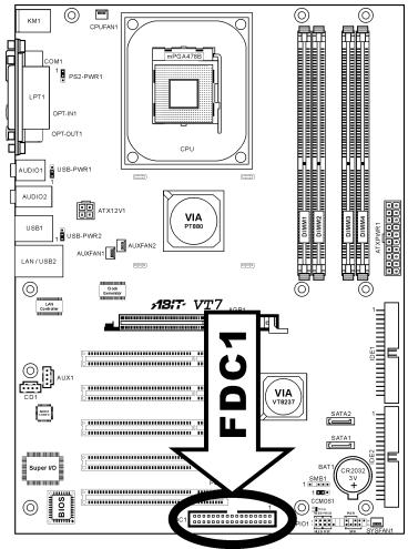
(10). IDE Connectors
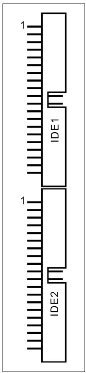
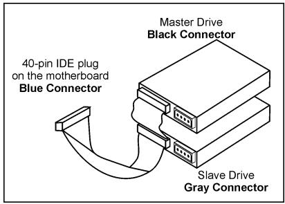
This motherboard provides two IDE ports to connect up to four IDE drives at Ultra ATA/100 mode by Ultra ATA/66 ribbon cables. Each cable has 40-pin 80-conductor and three connectors, providing two hard drives connection with motherboard. Connect the single end (blue connector) at the longer length of ribbon cable to the IDE port on motherboard, and the other two ends (gray and black connector) at the shorter length of the ribbon cable to the connectors on hard drives.
If you want to connect two hard drives together through one IDE channel, you must configure the second drive to Slave mode after the first Master drive. Please refer to the drives' documentation for jumper settings. The first drive connected to IDE1 is usually referred to as "Primary Master", and the second drive as "Primary Slave". The first drive connected to IDE2 is referred to as "Secondary Master" and the second drive as "Secondary Slave".
Keep away from connecting one legacy slow speed drive, like CD-ROM, together with another hard drive on the same IDE channel; this will drop your integral system performance.
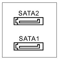
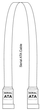
(11). Serial ATA Connectors
These connectors are provided to attach one Serial ATA device at each channel via Serial ATA cable. A RAID 0 or RAID 1 array is also available by software configuration.
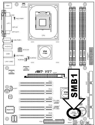
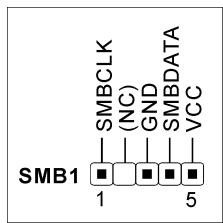
(12). System Management Bus Headers
This header is reserved for system management bus (SM bus). The SM bus is a specific implementation of an I^2C bus. I^2C is a multi-master bus, which means that multiple chips can be connected to the same bus and each one can act as a master by initiating a data transfer. If more than one master simultaneously tries to control the bus, an arbitration procedure decides which master gets priority.
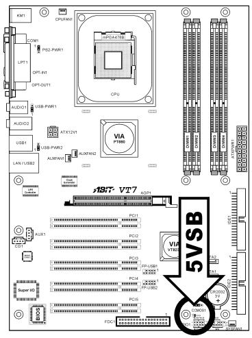
(13). Status Indicator
D18 (5VSB): This LED lights up when the power supply is connected with power source.

5VSB
D18
(14). Back Panel Connectors
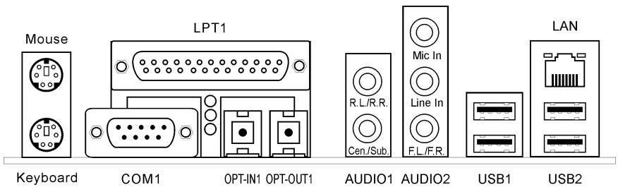
- Mouse: Connects to PS/2 mouse.
- Keyboard: Connects to PS/2 keyboard.
LPT1: Connects to printer or other devices that support this communication protocol.
COM1: Connects to external modem, mouse or other devices that support this communication protocol. - OPT-IN1: This connector provides an S/PDIF-In connection through optical fiber to digital multimedia devices.
- OPT-OUT1: This connector provides an S/PDIF-Out connection through optical fiber to digital multimedia devices.
- AUDIO01: R.L./R.R. (Rear Left / Rear Right): Connects to the rear left and rear right channel in the 5.1 channel audio system.
Cen./Sub. (Center / Subwoofer): Connects to the center and subwoofer channel in the 5.1 channel audio system.
AUDIO2:
Mic In: Connects to the plug from external microphone.
Line In: Connects to the line out from external audio sources.
F.L./F.R. (Front Left / Front Right): Connects to the front left and front right channel in the
5.1-channel or regular 2-channel audio system.
LAN: Connects to Local Area Network.
- USB1/USB2: Connects to USB devices such as scanner, digital speakers, monitor, mouse, keyboard, hub, digital camera, joystick etc.

Chapter 3. BIOS Setup
This motherboard provides a programmable EEPROM that you can update the BIOS utility. The BIOS (Basic Input/Output System) is a program that deals with the basic level of communication between processor and peripherals. Use the BIOS Setup program only when installing motherboard, reconfiguring system, or prompted to "Run Setup". This chapter explains the Setup Utility of BIOS utility.
After powering up the system, the BIOS message appears on the screen, the memory count begins, and then the following message appears on the screen:
PRESS DEL TO ENTER SETUP
If this message disappears before you respond, restart the system by pressing <Ctrl> + <Alt> + <Del> keys, or by pressing the Reset button on computer chassis. Only when it failed by these two methods can you restart the system by powering it off and then back on.
After pressing <Del> key, the main menu screen appears.
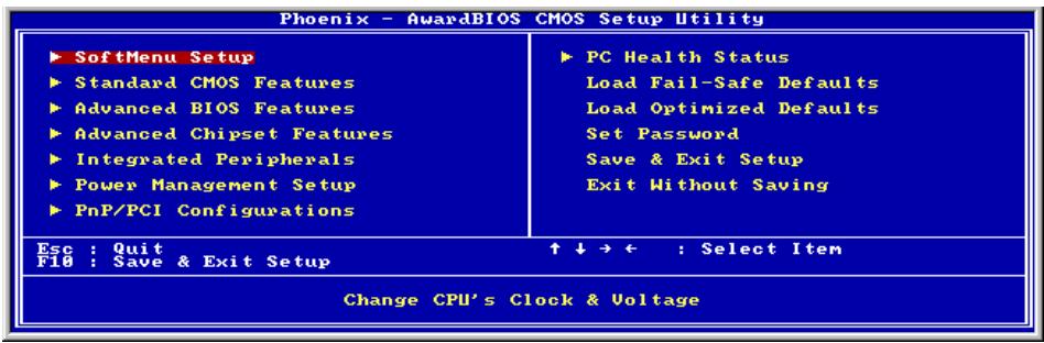
NOTE: In order to increase system stability and performance, our engineering staffs are constantly improving the BIOS menu. The BIOS setup screens and descriptions illustrated in this manual are for your reference only, may not completely match what you see on your screen.
3-1. SoftMenu Setup
The SoftMenu utility is ABIT's exclusive and ultimate solution in programming the CPU operating speed. All the parameters regarding CPU FSB speed, multiplier factor, the AGP & PCI clock, and even the CPU core voltage are all available at your fingertips.
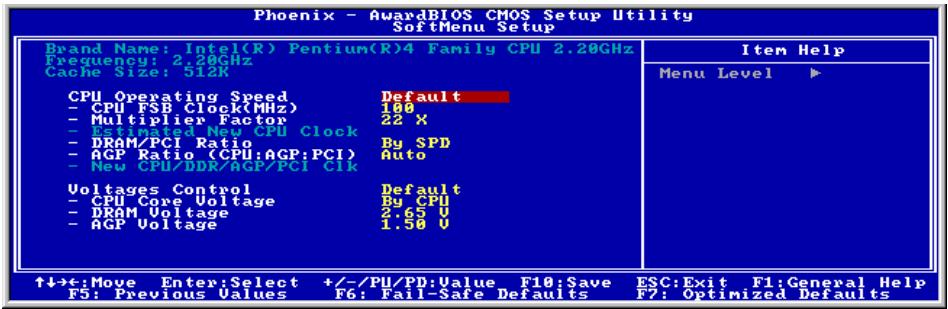
Brand Name:
This item displays the CPU model name, for example: Intel Pentium (R) 4.
Frequency:
This item displays the processor speed.
Cache Size:
This item displays the L2 cache size of your CPU.
CPU Operating Speed:
This item displays the CPU operating speed according to the type and speed of your CPU. You can also select the [User Define] option to enter the manual option.
User Define:
WARNING: The wrong settings of the multiplier and external clock in certain circumstances may cause CPU damage. Setting the working frequency higher than the PCI chipset or processor specs, may cause abnormal memory module functioning, system hangs, hard disk drive data lose, abnormal functioning of the VGA card, or abnormal functioning with other add-on cards. Using non-specification settings for your CPU is not the intention of this explanation. These should be used for engineering testing, not for normal applications.
There will be no guaranty for the settings beyond specification, any damage of any component on this motherboard or peripherals result therein is not our responsibility.
\* CPU FSB Clock (MHz):
This item sets the CPU Front Side Bus speed from 100 to 255. Due to the specification limit of the CPU you installed, the speed you set over its standard bus speed is supported, but not guaranteed.
\* Multiplier Factor:
This item sets the multiplier factor for the CPU you installed.
NOTE: Some processors might have this multiplier factor locked, so there is no way to choose a higher multiplier factor.
* Estimated new CPU clock:
This item displays the clock frequency sum up from the previous items [Ext. Clock] and [Multiplier Factor].
DRAM/PCI Ratio:
This item determines the frequency ratio between [DRAM] and [PCI].
When set to [By SPD], the BIOS will read the DRAM module SPD data and automatically set the DRAM clock by the value stored in it.
* AGP Ratio (CPU:AGP:PCI):
This item determines the frequency ratio among [CPU], [AGP], and [PCI].
* New CPU/DDR/AGP/PCI Clk:
This item displays the clock frequency of the previous setting among [CPU], [DDR], [AGP], and [PCI].
Voltages Control:
This option allows you to switch between CPU default and user-defined voltages. Leave this setting to default unless the current CPU type and voltage setting cannot be detected or is not correct. The option "User Define" enables you to select the Core Voltage manually.
CPU Core Voltage:
This item selects the CPU core voltage.
ATTENTION: A wrong voltage setting may cause the system unstable or even damage the CPU. Please leave it to default settings unless you are fully aware of its consequences.
DRAM Voltage:
This item selects the voltage for DRAM slot.
* AGP Voltage:
This item selects the voltage for AGP slot.
3-2. Standard CMOS Features
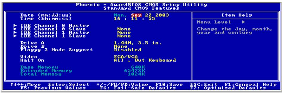
Date (mm:dd:yy):
This item sets the date you specify (usually the current date) in the format of [Month], [Date], and [Year].
Time (hh:mm:ss):
This item sets the time you specify (usually the current time) in the format of [Hour], [Minute], and [Second].
IDE Channel 0 Master/Slave and IDE Channel 1 Master/Slave:
Click
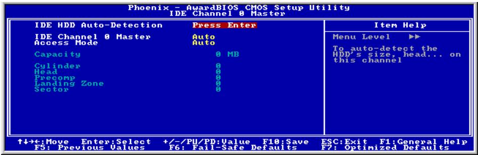
IDE HDD Auto-Detection:
This item allows you to detect the parameters of IDE drives by pressing
IDE Channel 0 Master/Slave and IDE Channel 1 Master/Slave:
When set to [Auto], the BIOS will automatically check what kind of IDE drive you are using. If you want to define your own drive by yourself, set it to [Manual] and make sure you fully understand the meaning of the parameters. Please refer to the instruction manual provided by the device's manufacturer to get the setting right.
| Access Mode:This item selects the mode to access your IDE devices. Leave this item to its default [Auto] setting to detect the access mode of your HDD automatically. |
| Capacity:This item displays the approximate capacity of the disk drive. Usually the size is slightly greater than the size of a formatted disk given by a disk-checking program. |
| Cylinder:This item configures the numbers of cylinders. |
| Head:This item configures the numbers of read/write heads. |
| Precomp:This item displays the number of cylinders at which to change the write timing. |
| Landing Zone:This item displays the number of cylinders specified as the landing zone for the read/write heads. |
| Sector:This item configures the numbers of sectors per track. |
| Back to Standard CMOS Features Setup Menu: |
| Drive A & Drive B:This item sets the type of floppy drives (usually only Drive A) installed. |
| Floppy 3 Mode Support:This item allows you to use “3 Mode Floppy Drive” in Japanese computer system by selecting drive A, B, or both. Leave this item to its default [Disabled] setting if you are not using this Japanese standard floppy drive. |
| Video:This item selects the type of video adapter used for the primary system monitor. |
| [EGA/VGA]: (Enhanced Graphics Adapter/Video Graphics Array) For EGA, VGA, SVGA and PGA monitor adapters. |
| [CGA 40]: (Color Graphics Adapter) Power up in 40-column mode. |
| [CGA 80]: (Color Graphics Adapter) Power up in 80-column mode. |
| [Mono]: (Monochrome adapter) Includes high-resolution monochrome adapters. |
| Halt On:This item determines whether the system stops if an error is detected during system boot-up. |
[All Errors]: The system-boot will stop whenever the BIOS detect a non-fatal error.
[No Errors]: The system-boot will not stop for any error detected.
[All, But Keyboard]: The system-boot will stop for all errors except a keyboard error.
[All, But Diskette]: The system-boot will stop for all errors except a diskette error.
[All, But Disk/Key]: The system-boot will stop for all errors except a diskette or keyboard error.
Base Memory:
This item displays the amount of base memory installed in the system. The value of the base memory is typically 640K for system with 640K or more memory size installed on the motherboard.
Extended Memory:
This item displays the amount of extended memory detected during system boot-up.
Total Memory:
This item displays the total memory available in the system.
3-3. Advanced BIOS Features
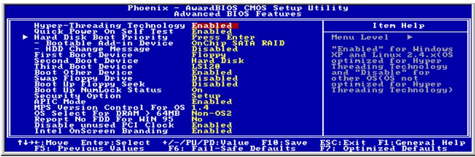
Hyper-Threading Technology
This item is used to enable the functionality of the processor with Hyper-Threading Technology and will appear only when using such processor.
The Hyper-Threading Technology helps your PC work more efficiently by maximizing processor resources and enabling a single processor to run two separate threads of software simultaneously, bringing forth greater performance and system responsiveness when running multiple applications at once.
Quick Power On Self Test:
When set to [Enabled], this item speeds up the Power On Self Test (POST) after powering on the system. The BIOS shorten or skip some check during the POST.
Hard Disk Boot Priority:
This item selects the hard disks booting priority. By pressing
This item functions only when there is the option of [Hard Disk] in any one of the First/Second/Third Boot Device items.
* Bootable Add-in Device:
This item allows you to select the bootable add-in device from [OnChip SATA RAID] or [PCI Slot Device] channel to serve as the bootable device listed in the item "Hard Disk Boot Priority".
HDD Change Message:
When set to [Enabled], a pop-up message will be displayed on the screen during the POST process if the hard drives installed in your system had been changed.
First Boot Device / Second Boot Device / Third Boot Device / Boot Other Device:
Select the drive to boot first, second and third in the [First Boot Device], [Second Boot Device], and [Third Boot Device] items respectively. The BIOS will boot the operating system according to the sequence of the drive selected. Set [Boot Other Device] to [Enabled] if you wish to boot from another device other than these three items.
Swap Floppy Drive:
When set to [Enabled], and the system is booting from the floppy drive, the system will boot from drive B instead of the regular drive A. There must be two floppy drives connected in the system to use this function.
Boot Up Floppy Seek:
When set to [Enabled], the BIOS will check whether the floppy disk drive is installed or not.
Boot Up NumLock Status:
This item determines the default state of the numeric keypad at system booting up.
[On]: The numeric keypad functions as number keys.
[Off]: The numeric keypad functions as arrow keys.
Security Option:
This item determines when the system will prompt for password - every time the system boots or only when enters the BIOS setup.
[Setup]: The password is required only when accessing the BIOS Setup.
[System]: The password is required each time the computer boots up.
NOTE: Don't forget your password. If you forget the password, you will have to open the computer case and clear all information in the CMOS before you can start up the system. But by doing this, you will have to reset all previously set options.
APIC Mode:
Leave this item to its default setting.
MPS Version Control For OS:
This item specifies which version of MPS (Multi-Processor Specification) this motherboard will use. Leave this item to its default setting.
OS Select For DRAM >64MB
This item allows you to access the memory that is over 64MB in OS/2. Leave this item to its default [Non-OS2] setting for operating system other than OS/2.
Report No FDD For WIN 95:
When set to [Enabled], this item allows you to run some older operating system without floppy disk drive. Leave this item to its default setting.
Disable Unused PCI Clock:
This option disables the clock of PCI slot that is not in use.
[Yes]: The system automatically detect the unused DIMM and PCI slots, and stop sending clock signal to these unused PCI slots.
[No]: The system always send clock signal to all PCI slots.
NOTE: Set this option to [No] setting if there are adapters that cannot be automatically detected by the system and will cause malfunction.
Intel OnScreen Branding:
This item determines whether to display the "Intel Inside" logo or not at system boots up.
3-4. Advanced Chipset Features
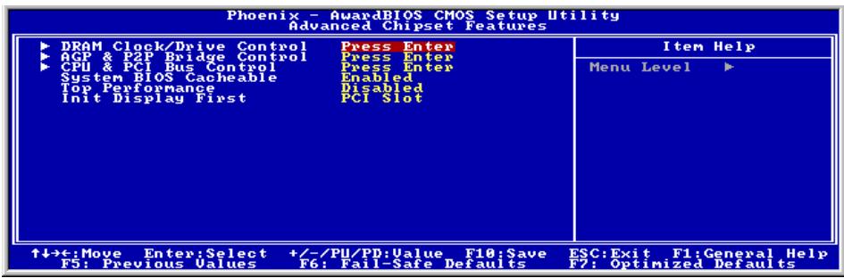
DRAM Clock/Drive Control:
Click
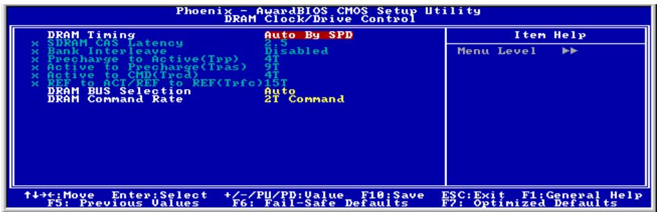
DRAM Timing:
This item determines the timing method of the DRAM modules.
[Manual]: This option allows you to select the best option in the following sub-items manually.
[Auto By SPD]: This option allows the system to run the SPD (Serial Presence Detect) data structure stored in the DRAM module automatically.
[Turbo]: This option allows the system to run at a speed faster than the one by [Auto By SPD] option.
[Ultra]: This option allows the system to run at a speed faster than the one by [Turbo] option.
NOTE: Leave this item to its default [Auto By SPD] option to avoid compatibility and stability problems.
- [SDRAM CAS Latency], [Bank Interleave], [Precharge to Active(Trp)], [Active to Precharge (Tras)], [Active to CMD(Trcd)], [REF to ACT/REF to REF(Trfc)]:
These sub-items display their default settings determined by [Auto By SPD] option, and are only able to be adjusted manually by the [Manual] option.
DRAM BUS Selection:
This item determines the channel of DRAM modules from [Single Channel] or [Dual Channel]. The [Single Channel] option allows a standard 64-bit access rate. The [Dual Channel] option will have a double 128-bit access rate. Leave this item to its default [Auto] setting to have it selected automatically.
NOTE: It is highly recommended to use the DRAMs of the identical brand name and specification for slots [DIMM1] + [DIMM3] or slots [DIMM2] + [DIMM4] in order to achieve a better performance.
DRAM Command Rate:
This item determines the wait state of commands. Set it to [2T Command] for system compatibility or [1T Command] for system performance.

Back to Advanced Chipset Features Setup Menu:
AGP & P2P Bridge Control:
Click
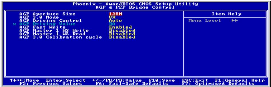
AGP Aperture Size:
This item specifies the amount of system memory that can be allocated by the AGP device. The aperture is a portion of the PCI memory address range dedicated for graphics memory address space.
AGP 3.0 Mode:
This item selects the data transfer rate of AGP device. A higher rate delivers faster and better graphics to your system. Make sure your graphics card supports the mode you select.
NOTE: This item will be changed into "AGP 2.0 Mode" when not installing graphics card of AGP 3.0 specifications.
AGP Driving Control:
Set this item to [Manual] option only if there are compatible problems with some graphics cards. When set to [Manual], you must select a value in the following [AGP Driving Value] item.
* AGP Driving Value:
This item determines the value for AGP Driving Control.
AGP Fast Write:
This item determines the AGP Fast Write feature, a technology that allows the CPU to write directly to the graphics card without passing anything through the system memory so as to improve the AGP speed. Set to [Enabled] only when the installed AGP card supports the function.
AGP Master 1 WS Write:
When set to [Enabled], one wait state is inserted to the AGP write cycle, allowing for greater stability.
AGP Master 1 WS Read:
When set to [Enabled], one wait state is inserted to the AGP read cycle, allowing for greater stability.
AGP 3.0 Calibration cycle:
This item controls the time cycle between AGP and North Bridge. You may try the [Enabled] option if problems occurred when using some graphics cards of AGP 3.0 specifications.
NOTE: This item appears only when installing graphics card of AGP 3.0 specifications.

Back to Advanced Chipset Features Setup Menu:
CPU & PCI Bus Control:
Click
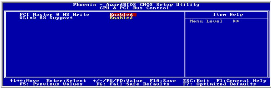
PCI Master 0 WS Write:
[Enabled]: Writes to the PCI bus are executed with zero wait state (immediately) when PCI bus is ready to receive data.
[Disabled]: The system will wait one state before data is written to the PCI bus.
VLink 8X Support:
[Enabled]: The speed of VLink that links the North Bridge and South Bridge is 8x.
[Disabled]: The speed of VLink that links the North Bridge and South Bridge is 4x.

Back to Advanced Chipset Features Setup Menu:
System BIOS Cacheable:
When set to [Enabled], accesses to the system BIOS ROM addressed at F0000H-FFFFFFH are cached, provided that the cache controller is enabled. The larger the range of the Cache RAM, the higher the efficiency of the system will be.
Top Performance:
This item enables the DRAM performance if there are no compatible issues occurred.
Init Display First:
This item selects to initialize AGP or PCI Slot first when the system boots.
[AGP]: When the system boots, it will first initialize AGP.
[PCI Slot]: When the system boots, it will first initialize PCI.
3-5. Integrated Peripherals
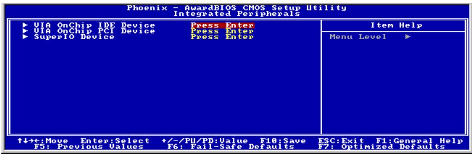
VIA OnChip IDE Device:
Click
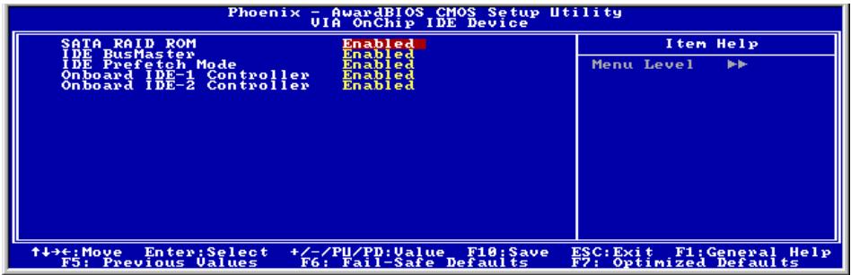
SATA RAID ROM:
This item allows you to use the boot ROM of onchip Serial ATA RAID to boot-up system.
IDE Bus Master:
This option enables or disables the IDE bus mastering capability under the DOS environment.
IDE Prefetch Mode:
Leave this item to its default [Enabled] setting to allow the data and addresses to be stored in the internal chip buffer. This is helpful in reducing access time to achieve better performance.
Onboard IDE-1 Controller:
This item allows you to enable or disable the primary and secondary IDE controller. Select [Disabled] if you want to add a different hard drive controller.
Onboard IDE-2 Controller:
The description is same as the Onboard IDE-1 Controller.

Back to Integrated Peripherals Setup Menu:
VIA OnChip PCI Device:
Click
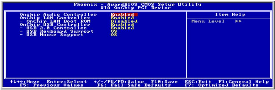
OnChip Audio Controller:
This option enables or disables the audio controller.
OnChip LAN Controller:
This option enables or disables the LAN controller.
\* OnChip LAN Boot ROM:
This item enables or disables the Boot ROM on LAN controller.
OnChip USB Controller:
This option enables or disables the USB controller.
\* USB 2.0 Controller:
This option enables or disables the USB 2.0 controller.
\* USB Keyboard Support:
This item allows you to select [BIOS] for using USB keyboard in DOS environment, or [OS] in OS environment.
* USB Mouse Support:
This item allows you to select [BIOS] for using USB mouse in DOS environment, or [OS] in OS environment.

Back to Integrated Peripherals Setup Menu:
SuperIO Device:
Click
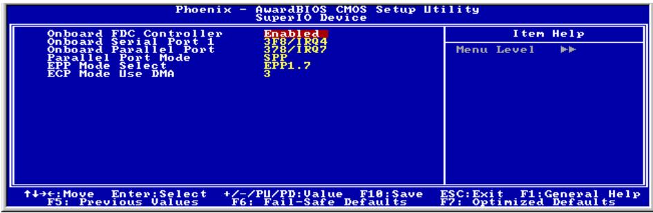
Onboard FDC Controller:
This option enables or disables the onboard FDC controller.
Onboard Serial Port 1:
This item determines which I/O addresses the onboard Serial Port controller will access.
[Auto]: The system automatically select an I/O address for the onboard Serial Port.
[3F8/IRQ4, 2F8/IRQ3, 3E8/IRQ4, 2E8/IRQ3]: Allows you to manually select an I/O address for the onboard Serial Port.
[Disabled]: Disables the onboard Serial Port.
Onboard Parallel Port:
This item specifies the I/O address used by the parallel port.
[Disabled]: This option prevents the parallel port from accessing any system resources. When the value of this option is set to [Disabled], the printer port becomes unavailable.
[378/IRQ7]: This option allows the parallel port to use [378/IRQ7] as its I/O port address. The majority of parallel ports on computer systems use IRQ7 and I/O Port 378H as the standard setting.
[278/IRQ5]: This option allows the parallel port to use [278/IRQ5] as its I/O port address.
[3BC/IRQ7]: This option allows the parallel port to use [3BC/IRQ7] as its I/O port address.
* Parallel Port Mode:
This item specifies the parallel port mode.
[Normal]: Allows the standard parallel port mode to be used.
[SPP]: (Standard Parallel Port) Allows bi-directional parallel port operation at normal speed.
[EPP]: (Enhanced Parallel Port) Allows bi-directional parallel port operation at maximum speed.
[ECP]: (Extended Capabilities Port) Allows bi-directional parallel port operation at a speed faster than the normal mode's data transfer rate.
[ECP + EPP] : Allows parallel port operation at ECP and EPP mode.
EPP Mode Select:
This item selects the EPP mode.
ECP Mode Use DMA:
This item selects the DMA channel of the parallel port.
3-6. Power Management Setup
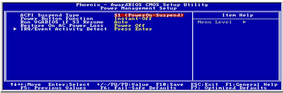
ACPI Suspend Type:
This item selects the type of Suspend mode.
[S1(PowerOn-Suspend)]: Enables the Power On Suspend function.
[S3(Suspend-To-RAM)]: Enables the Suspend to RAM function.
Power Button Function:
This item selects the method of powering off your system:
[Delay 4 Sec.]: Pushing the power button for more than 4 seconds will power off the system. This will prevent the system from powering off in case you accidentally hit or pushed the power button.
[Instant-Off]: Pressing and then releasing the power button at once will immediately power off the system.
Run VGABIOS if S3 Resume:
Three options are available: Auto Yes No. The default setting is Auto. This item can let you choose when S3 resume active, the VGA BIOS need to be initiative or not.
Restore On AC Power Loss:
This item selects the system action after an AC power failure.
[Power Off]: When power returns after an AC power failure, the system's power remains off. You must press the Power button to power-on the system.
[Power On]: When power returns after an AC power failure, the system's power will be powered on automatically.
[Last State]: When power returns after an AC power failure, the system will return to the state where you left off before power failure occurs. If the system's power is off when AC power failure occurs, it will remain off when power returns. If the system's power is on when AC power failure occurs, the system will power-on when power returns.
IRQ/Event Activity Detect:
Click
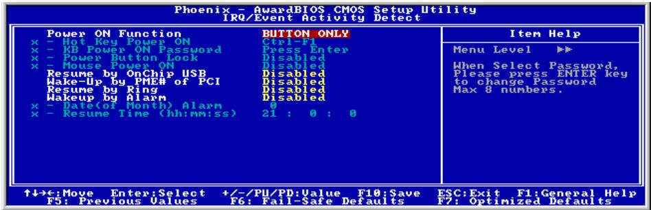
Power On Function:
This item selects the way to power on the system.
[Button Only]: Power on the system by clicking the Power Button only.
[Password]: Power on the system by typing the password you want for up to 8 characters. Please follow the on-screen instruction to confirm the password.
[Hot Key]: Power on the system by clicking the hot-key combination you set.
[Mouse]: Power on the system by clicking the button of PS/2 mouse.
Hot Key Power ON:
This item powers on the system by clicking the hot-key combination you set from Ctrl + F1
* KB Power ON Password:
This item appears only when setting the item "Power On Function" to [Password]. You may type in the password you want in this option.
NOTE: Do not forget your password, or you will have to clear the CMOS and reset all parameters in order to utilize this function again.
* Power Button Lock:
This item appears only when setting the item "Power On Function" to [Password].
After setting the item "Power On Function" to [Password], and then entering the password for [KB Power On Password], setting this item to [Enabled] will disable the Power-Button function. Typing the password set in the item "KB Power ON Password" will be the only way to power on the system.
\* Mouse Power ON:
This item appears only when setting the item "Power On Function" to [Mouse].
After setting the item "Power On Function" to [Mouse], setting this item to [Enabled] will allow you to power on the system by clicking the button of PS/2 mouse.
Resume by OnChip USB:
Two options are available: Disabled or Enabled. The default setting is Disabled. When set to Enabled, any event affecting from onchip USB will awaken a system that has been powered down.
Wake-Up by PME# of PCI:
When set to [Enabled], access to the onboard LAN or a PCI card such as a modem or LAN card will cause the system to wake up. The PCI card must support the wake up function.
Resume by Ring:
Two options are available: Disabled or Enabled. The default setting is Disabled. When set to Enabled, any event affecting from Modem Ring will awaken a system that has been powered down.
Wakeup by Alarm:
When set to [Enabled], you can set the date and time you would like the Soft-Off PC to power-on in the "Date (of Month) Alarm" and "Time (hh:mm:ss) Alarm" items. However, if the system is being accessed by incoming calls or the network (Resume On Ring/LAN) prior to the date and time set in these items, the system will give priority to the incoming calls or network instead.
\* Date (of Month) Alarm:
[0]: This option power-on the system everyday according to the time set in the "Time (hh:mm:ss) Alarm" item.
[1-31]: This option selects a date you would like the system to power-on. The system will power-on on the date set, and the time set in the "Time (hh:mm:ss) Alarm" item.
* Time (hh:mm:ss) Alarm:
This item sets the time you would like the system to power-on.
3-7. PnP/PCI Configurations
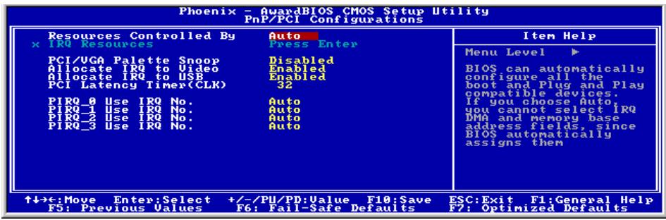
Resources Controlled By:
This item configures all of the boot and Plug-and-Play compatible devices.
[Auto]: The system will automatically detect the settings.
[Manual]: Choose the specific IRQ resources in the "IRQ Resources" menu.
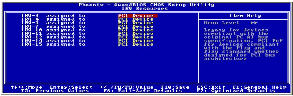
* IRQ Resources:
Click
This item sets each system interrupt to either [PCI Device] or [Reserved].
Back to PnP/PCI Configurations Setup Menu:
PCI/VGA Palette Snoop:
This item determines whether the MPEG ISA/VESA VGA cards can work with PCI/VGA or not.
[Enabled]: MPEG ISA/VESA VGA cards work with PCI/VGA.
[Disabled]: MPEG ISA/VESA VGA cards do not work with PCI/VGA.
Allocate IRQ To Video:
This item assigns an IRQ for the VGA card installed.
[Enabled]: Automatically assign an IRQ for the VGA card installed.
[Disabled]: The IRQ that was previously occupied by the VGA card will be available for new device.
Allocate IRQ To USB:
This item assigns an IRQ for the USB device connected.
[Enabled]: Automatically assign an IRQ for the USB device connected.
[Disabled]: The IRQ that was previously occupied by the USB device connected will be available for new device.
PCI Latency Timer(CLK):
This item controls how long each PCI device can hold the bus before another takes over. When set to higher values, every PCI device can conduct transactions for a longer time and thus improve the effective PCI bandwidth. For better PCI performance, you should set the item to higher values.
PIRQ_0 Use IRQ No. ~PIRQ_3 Use IRQ No.:
This item specifies the IRQ number manually or automatically for the devices installed on PCI slots.
For the relations between the hardware layout of PIRQ (the signals from the VIA VT8237 chipset), INT# (means PCI slot IRQ signals) and devices, please refer to the table below:
| Signals | AGP | LAN | PCI-1 | PCI-2 | PCI-3 | PCI-4 | PCI-5 | SATA |
| PIRQ_0 Assignment | INT A | INT A | INT A | INT D | INT C | INT B | INT A | |
| PIRQ_1 Assignment | INT B | INT B | INT A | INT D | INT C | INT B | INT A | |
| PIRQ_2 Assignment | INT C | INT B | INT A | INT D | INT C | |||
| PIRQ_3 Assignment | INT D | INT C | INT B | INT A | INT D | |||
| PIRQ_4 Assignment | ||||||||
| PIRQ_5 Assignment | ||||||||
| PIRQ_6 Assignment | ||||||||
| PIRQ_7 Assignment |
NOTE:
PCI slot 1 shares IRQ signals with PCI slot 5, AGP slot, and LAN.
- If you want to install two PCI cards into those PCI slots that share IRQ with one another at the same time, you must make sure that your OS and PCI devices' driver supports the IRQ sharing function.
3-8. PC Health Status
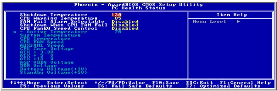
Shutdown Temperature:
This item sets the temperature that would shutdown the system automatically in order to prevent system overheats.
NOTE: This item only works for the OS with ACPI activated.
CPU Warning Temperature:
This item selects the CPU's warning temperature limit. Once the system has detected that the CPU's temperature exceeded the limit, warning beeps will sound.
NOTE: The onboard hardware monitor function is capable of detecting these system health conditions. If you want a warning message to pop-up or a warning alarm to sound when an abnormal condition occurs, you must install the "Hardware Doctor" utility. This utility is included in the "Driver & Utility CD" that came packed with this motherboard.
FAN Fail Alarm Selectable:
This item selects the fan that will be monitored for malfunction.
Shutdown When CPU FAN Fail:
When set to [Enabled], the system will be shut down if the CPU fan is not running.
NOTE: This item only works for the OS with ACPI activated.
CPU FanEQ Speed Control:
This item allows you to control the CPU fan speed down to a specific percentage.
When set to a specific percentage, the CPU fan speed will run at the percentage you set in this item if the temperature limit set in the item "Active Temperature" is not exceeded.
The CPU fan speed will run at 100% regardless of what the percentage you set in this item if the temperature limit set in the item "Active Temperature" is exceeded.
Active Temperature:
This item sets the temperature limit that would activate the function of "CPU FanEQ Speed Control" option.
All Voltages, Fans Speed and Thermal Monitoring:
These unchangeable items list the current status of the CPU and environment temperatures, fan speeds, and system power voltage.
NOTE: The hardware monitoring features for temperatures, fans and voltages will occupy the I/O address from 294H to 297H. If you have a network adapter, sound card or other add-on cards that might use those I/O addresses, please adjust your add-on card I/O address to avoid using these addresses.
3-9. Load Fail-Safe Defaults
This option loads the BIOS default values for the most stable, minimal-performance system operations.
3-10. Load Optimized Defaults
This option loads the BIOS default values that are factory settings for optimal-performance system operations.
3-11. Set Password
This option protects the BIOS configuration or restricts access to the computer itself.
3-12. Save & Exit Setup
This option saves your selections and exits the BIOS setup menu.
3-13. Exit Without Saving
This option exits the BIOS setup menu without saving any change.

Appendix A. Install VIA 4-in-1 Driver
NOTE: Please install this VIA 4-in-1 driver first after having installed the Windows operating system.
The installation procedures and screen shots in this section are based on Windows 2000 operating system. For those of other OS, please follow its on-screen instruction.
Insert the Driver & Utility CD into CD-ROM drive, it should execute the installation program automatically. If not, double-click the execution file at the main directory of this CD to enter the installation menu.
After entering the installation menu, move your curser to [Drivers] tab. Click [VIA 4in1 Driver]. The following screen appears.
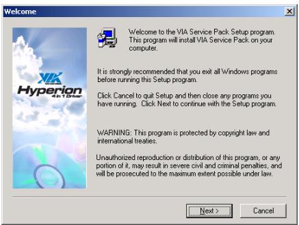
1. Click [Next].
![ABIT VT7 - Click [Next]. - 1](/content/2025/01/174600/images/57e3955d9cbad0e8f24147ca182850e9ac3364dfd5ba28ea02bd3276d869a44b.jpg)
2. Click [Yes].
![ABIT VT7 - Click [Yes]. - 1](/content/2025/01/174600/images/e55ba73c10682b895c8c20489088d6802cf370dca00a236c5311f52ae78e05bf.jpg)
3. Click [Next].
![ABIT VT7 - Click [Next]. - 1](/content/2025/01/174600/images/4999691f1f9a9cd8d456fd57e71aae734cd0b0e24d73587a9aff5642fc5b1d94.jpg)
4. Click [Next].
![ABIT VT7 - Click [Next]. - 1](/content/2025/01/174600/images/221d2e383290cb456e6d966180dd88af8ba44da7c62e514840f323e54521dc18.jpg)
5. Click [Next].
![ABIT VT7 - Click [Next]. - 1](/content/2025/01/174600/images/c77dc6dd71e403c7315bf82781c206baeed717d0b7a6267be0c7c90737ca73bd.jpg)
6. Click [Next].
![ABIT VT7 - Click [Next]. - 1](/content/2025/01/174600/images/9112f4d3dd38ddc28a7bfa91e358a401082697fe6e0e9d255d97ff6b6425710b.jpg)
- Choose [Yes, I want to restart my computer now.], and click [OK] to complete setup.
Appendix B. Install Audio Driver
The installation procedures and screen shots in this section are based on Windows 2000 operating system. For those of other OS, please follow its on-screen instruction.
Insert the Driver & Utility CD into CD-ROM drive, it should execute the installation program automatically. If not, double-click the execution file at the main directory of this CD to enter the installation menu.
After entering the installation menu, move your cursor to [Drivers] tab. Click [Audio Driver]. The following screen appears.
1. Click [Next].
![ABIT VT7 - Click [Next]. - 1](/content/2025/01/174600/images/f8dcc79d58a17b24723f236af0962e7b37ab7afd9748f714d2bb2b1afda87ff7.jpg)
2. Click [Yes].
![ABIT VT7 - Click [Yes]. - 1](/content/2025/01/174600/images/e0ec51bd41db2da8dd606aabcdb055592b18b157ba900a6150876efbdffd4868.jpg)
- Choose [Yes, I want to restart my computer now.], and click [Finish] to complete setup.
![ABIT VT7 - Click [Yes]. - 2](/content/2025/01/174600/images/e96da68be3eb074c13d7b14b797f6060e7ba5f0a3e32285e056883e5da70c78c.jpg)
- After the system restarted, a shortcut icon appears at the right corner of Windows task bar.
![ABIT VT7 - Click [Yes]. - 3](/content/2025/01/174600/images/a9932fa343832ece160785543d6fa8c759b5fad6e9cf98b0d738d531977c5269.jpg)
- In this Speaker Configuration tab, select [6 channels mode for 5.1 speakers output] to enable 6-channel audio system.
![ABIT VT7 - Click [Yes]. - 4](/content/2025/01/174600/images/6f410577f73746c3206751fbfb528f13219a86af50b91afd91c478d2ffe4da1a.jpg)
Appendix C. Install LAN Driver
The installation procedures and screen shots in this section are based on Windows 2000 operating system. For those of other OS, please follow its on-screen instruction.
Insert the Driver & Utility CD into CD-ROM drive, it should execute the installation program automatically. If not, double-click the execution file at the main directory of this CD to enter the installation menu.
After entering the installation menu, move your cursor to [Drivers] tab. Click [LAN Driver]. The following screen appears.
- Click [OK] to exit the installation.

Appendix D. Install VIA USB 2.0 Driver
NOTE: There is no need to install VIA USB 2.0 driver for the Windows XP operating system with Service Pack 1 already installed. Please run the Windows update for the latest Service Pack.
The installation procedures and screen shots in this section are based on Windows 2000 operating system. For those of other OS, please follow its on-screen instruction.
Insert the Driver & Utility CD into CD-ROM drive, it should execute the installation program automatically. If not, double-click the execution file at the main directory of this CD to enter the installation menu.
After entering the installation menu, move your curser to [Drivers] tab. Click [VIA USB 2.0 Driver]. The following screen appears.
1. Click [Next].
![ABIT VT7 - Click [Next]. - 1](/content/2025/01/174600/images/ab4f5c2fc778439b1a3e80c1c69863ed19c82aa15096b0aa1d02d8dfad8dee3c.jpg)
2. Click [Yes].
![ABIT VT7 - Click [Yes]. - 1](/content/2025/01/174600/images/dd39d8a6c149fa4ec45b892b602028d8857645f21e5c8c42f8d58b0045c7b8e8.jpg)
3. Click [Next].
![ABIT VT7 - Click [Next]. - 1](/content/2025/01/174600/images/97cfc21dc4a718fe83fec30aef38516fe95e6d95a5e8f9e86c304b96b3ae1239.jpg)
4. Click [Yes].
![ABIT VT7 - Click [Yes]. - 1](/content/2025/01/174600/images/15876bbf2063637b77aad0089a8a3f02c9bae8d440e70833f08c5f69f303dfca.jpg)
5. Click [Yes].
![ABIT VT7 - Click [Yes]. - 1](/content/2025/01/174600/images/009104b2dfc4793ce2c41d9508c5fbaa3b1caac7df652357d6dd0c4db2e2deec.jpg)
6. Click [Yes].
![ABIT VT7 - Click [Yes]. - 1](/content/2025/01/174600/images/739dc31ee3acb19b6d9c26311df6961816798735ecf7b2b1428cfeb775e0c67a.jpg)
7. Click [OK].
![ABIT VT7 - Click [OK]. - 1](/content/2025/01/174600/images/185ff350269d3680d68cad0a78036d5a7be51b1b073ae510cc7f9bc650a67c55.jpg)
8. Click [Print to File].
![ABIT VT7 - Click [Print to File]. - 1](/content/2025/01/174600/images/3d05f35af627e750a623b876d829a6d626fd447a35247f39324865c4e1bf5dab.jpg)
9. Click [OK].
Appendix E. Install Serial ATA RAID Driver
The installation procedures and screen shots in this section are based on Windows 2000 operating system. For those of other OS, please follow its on-screen instruction.
Insert the Driver & Utility CD into CD-ROM drive, it should execute the installation program automatically. If not, double-click the execution file at the main directory of this CD to enter the installation menu.
After entering the installation menu, move your cursor to [Drivers] tab. Click [VIA SATA RAID Driver]. The following screen appears.
1. Click [Next].
![ABIT VT7 - Click [Next]. - 1](/content/2025/01/174600/images/a8748b0e597008e47d9f0dce7dc8e76a23d95c5b568479d6e30dbba75ef8fdef.jpg)
2. Click [Next].
![ABIT VT7 - Click [Next]. - 1](/content/2025/01/174600/images/0c3e18fed2d0565cf3cee2beac2d0290228b565123110b8713b54bcfe3ef34ad.jpg)
3. Click [Next].
![ABIT VT7 - Click [Next]. - 1](/content/2025/01/174600/images/5af67dd3f84a4293ab8887e9f581f71aa981b545ea563fcdc3a25173e80f3efa.jpg)
4. Click [Next].
![ABIT VT7 - Click [Next]. - 1](/content/2025/01/174600/images/f20059b4386c718fb30acf454e75891cc014a372648423186eb8d7bda4b7327f.jpg)
5. Click [Yes].
![ABIT VT7 - Click [Yes]. - 1](/content/2025/01/174600/images/ef2d6842f93ed4ae9d96bbf2aa22b93e03f7ba6614e0647b671c9fe4ca17da58.jpg)
- Choose [Yes, I want to restart my computer now.], and click [Finish] to complete setup.
![ABIT VT7 - Click [Yes]. - 2](/content/2025/01/174600/images/99ddbb5833435f3e57ed4bbc053ad26879eebf689f76c2d706e58aa41ab2493a.jpg)
- Execute the "VIA RAID Tool" by entering the Windows Menu [Start] [Programs] [VIA] [RAID].
![ABIT VT7 - Click [Yes]. - 3](/content/2025/01/174600/images/462cad771fe79a07438593740255ddd5b66739ed5e15e7e383e9d792458639cb.jpg)
- This is the "VIA RAID Tool" configuration menu. For more information on how to operate, please refer to the "Help" menu.
Appendix F. ABIT EQ (The Hardware Doctor Utility)
ABIT EQ is a self-diagnostic system for PC based on motherboards designed and manufactured by ABIT Computer Corporation. It will protect PC Hardware by monitoring critical items of Power Supply Voltage, CPU & System Fans Speed, and CPU & System Temperature.
The installation procedures and screen shots in this section are based on Windows 2000 operating system. For those of other OS, please follow its on-screen instruction.
Insert the Driver & Utility CD into CD-ROM drive, it should execute the installation program automatically. If not, double-click the execution file at the main directory of this CD to enter the installation menu.
After entering the installation menu, move your cursor to [ABIT Utility] tab. Click [ABIT EQ]. The following screen appears.
1. Click [Next].
2. Click [Next].
3. Click [Next].
4. Choose [Yes, I want to restart my computer now.] and click [Finish] to complete setup.
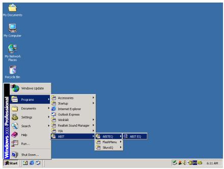
- Execute the ABIT EQ by entering the Windows Menu [Start] [Programs] [ABIT] [ABIT EQ].
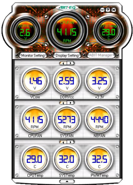
- This screen appears. ABIT EQ shows you the status of Voltage, Fan Speed, and Temperature readings as well. (The item names in this screen shot are for reference only, may not be exactly the same as what you see on your monitor.)
Appendix G. FlashMenu (BIOS Update Utility)
ABIT FlashMenu is the most stable Windows-based BIOS flash available. No more worries from crashing. With one click of BIOS updating, ABIT users can flash their BIOS more easily and in less time.
The installation procedures and screen shots in this section are based on Windows 2000 operating system. For those of other OS, please follow its on-screen instruction.
Insert the Driver & Utility CD into CD-ROM drive, it should execute the installation program automatically. If not, double-click the execution file at the main directory of this CD to enter the installation menu.
After entering the installation menu, move your cursor to [ABIT Utility] tab. Click [FlashMenu]. The following screen appears.
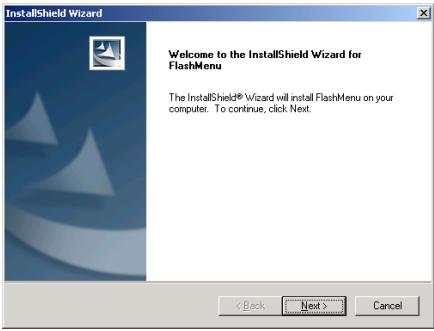
1. Click [Next].
![ABIT VT7 - Click [Next]. - 1](/content/2025/01/174600/images/d1bb1bccddec96a3fbcef18cca83ac1199175ff591e9b93fb5b15c1a0d5975b3.jpg)
2. Click [Next].
![ABIT VT7 - Click [Next]. - 1](/content/2025/01/174600/images/22ec87166ba3222355c56e8832eeb3355f8908396a5ea96cc28b8b8c6f988327.jpg)
3. Click [Next].
![ABIT VT7 - Click [Next]. - 1](/content/2025/01/174600/images/ace97dd6e9cae25d9d792378fb598304e86ad4c3b7583d9d2928b6ebb6d29bdf.jpg)
4. Click [Finish] to complete setup.
![ABIT VT7 - Click [Finish] to complete setup. - 1](/content/2025/01/174600/images/8d0779f20f9d8d844acc593bfe9279251544687fb534b2b336d24406e1c55742.jpg)
- Execute the FlashMenu by entering the Windows Menu [Start] [Programs] [ABIT] [FlashMenu].
![ABIT VT7 - Click [Finish] to complete setup. - 2](/content/2025/01/174600/images/da4ecc49eb0e75105268651dc9d71acb8fcd883d14043a4cbf5a96822f83b3fd.jpg)
- This FlashMenu screen appears. You can easily update the BIOS from clicking [Update From File], [One Click LiveUpdate], or [LiveUpdate Step by Step] button.
Appendix H. Troubleshooting (Need Assistance?)
Q & A:
Q: Do I need to clear the CMOS before I use a new motherboard to assemble my new computer system?
A: Yes, we highly recommend that you clear the CMOS before installing a new motherboard. Please move the CMOS jumper from its default 1-2 position to 2-3 for a few seconds, and then back. When you boot up your system for the first time, follow the instructions in the user's manual to load the optimized defaults.
Q: If my systems hang when I update the BIOS or set the wrong CPU parameters, what should I do?
A: Whenever you update the BIOS or if the system hangs due to wrong CPU parameters setting, always clear CMOS jumper before booting up again.
Q: Why the system fails to boot up again right after a mechanical power-off?
A: Please keep a 30-second interval between each mechanical power On/Off.
Q: Why the system failed to boot up and nothing was displayed on the screen after I did some over-clocking or non-standard settings inside the BIOS? Is the motherboard dead? Do I need to return it to where I bought from or go through an RMA process?
A: It should not cause hardware or permanent damage to motherboard when BIOS settings were changed from default to over-clocking or non-standard status.
We suggest the following three troubleshooting methods to discharge CMOS data, recover the hardware default status, and then make the motherboard working again. No need to bother returning the motherboard to where you bought from or go through an RMA process.
Step 1. Switch off the power supply unit and then switch it on again after one minute. If there is no power switch on the power supply unit, disconnect its power cord for one minute and then connect it back.
Press and hold the key to enter the BIOS setup page to do the correct settings.
If the situation remains the same, repeat the procedures in Step 1 for three times, or try Step 2.
Step 2. Switch off the power supply unit or disconnect the power cord. Open the chassis cover.
Locate the CCMOS jumper near the button battery. Change the jumper position from default 1-2 to 2-3 for one minute to discharge the CMOS data, and then put it back to default 1-2 position.
Close the chassis and switch on the power supply unit or plug in the power cord. Press the power-on button to boot up system. If it works, hit <Del> key to enter the BIOS setup page to do the correct settings.
If the situation remains the same, try Step 3.
Step 3. The same procedure as Step 2, but in the meantime of discharging the CMOS data, pull out ATX power connectors from motherboard and remove the button battery during CMOS discharging.
Q: How can I get a quick response to my request for technical support?
A: Be sure to follow the guidelines as stated in the "Technical Support Form" section of this manual.
If you have a problem during operation, in order to help our technical support personnel quickly determine the problem with your motherboard and give you the answers you need, before filling in the technical support form, eliminate any peripheral that is not related to the problem, and indicate it on the form. Fax this form to your dealer or to the company where you bought the hardware in order to benefit from our technical support. (You can refer to the examples given below)
Example 1:
With a system including: motherboard (with CPU, DRAM, COAST...) HDD, CD-ROM, FDD, VGA CARD, MPEG CARD, SCSI CARD, SOUND CARD, etc. After the system is assembled, if you cannot boot up, check the key components of the system using the procedure described below. First remove all interface cards except the VGA card and try to reboot.
If you still cannot boot up: Try installing another brand/model VGA card and see if the system will start. If it still does not start, note the VGA card model, motherboard model, Bios identification number, CPU on the technical support form (refer to main instructions), and describe the problem in the problem description space provided.
If you can boot up: Insert the interface cards you have removed back into the system, one by one and try to start the system each time you insert a card, until the system will not start. Keep the VGA card and the interface card that caused the problem inserted on the motherboard, remove any other cards or peripheral, and start again. If you still cannot start, note the information related to both cards in the add-on Card space provided, and don't forget to indicate the motherboard model, version, BIOS identification number, CPU (refer to main instructions), and give a description of the problem.
Example 2:
With a system including the motherboard (with CPU, DRAM, COAST...) HDD, CD-ROM, FDD, VGA CARD, LAN CARD, MPEG CARD, SCSI CARD, SOUND CARD, after assembly and after having installed the Sound Card Driver, when you restart the system, when it runs the Sound Card Driver, it resets automatically. This problem may be due to the Sound Card Driver. During the Starting DOS... procedure, press SHIFT (BY-PASS) key, to skip CONFIG.SYS and AUTOEXEC.BAT; edit CONFIG.SYS with a text editor, and in function the line that loads the Sound Card Driver, add a remark REM, in order to disable the Sound Card Driver. See the example below.
CONFIG.SYS:
DEVICE=C:\DOS\HIMEM.SYS
DEVICE=C:\DOS\EMM386.EXE HIGHSCAN
DOS=HIGH, UMB
FILES=40
BUFFERS=36
REM DEVICEHIGH=C:\PLUGPLAY\DWCFGMG.SYS
LASTDRIVE =
Restart the system. If the system starts and does not reset, you can be sure that the problem is due to the Sound Card Driver. Write down the Sound Card model, motherboard model, BIOS identification number on the technical support file (refer to main instructions), and describe the problem in the space provided.
We will show you how to fill the "Technical Support Form".
Main instructions:
To fill in this "Technical Support Form", refer to the step-by-step instructions given below:
1*.MODEL: Note the model number given in your user's manual.
Example: VT7
2. Motherboard model number (REV): Note the motherboard model number labeled on the motherboard as "REV:.*".
Example: REV: 1.01
- BIOS ID and Part Number: See the on screen message.
- DRIVER REV: Note the driver version number indicated on the DEVICE DRIVER disk (if any) as "Release .". For example:
5*. OS/APPLICATION: Indicate the operating system and applications you are running on the system.
Example: MS-DOS 6.22
Windows 98 SE, Windows 2000, etc....

6^* .CPU:Indicate the brand and the speed (MHz) of your CPU.
Example:(A) In the "Brand" space, write "Intel"; in the "Specifications" space, write "Pentium® 4 1.9GHz".
- HDD: Indicate the brand and specifications of your HDD(s); specify if the HDD is using IDE1 or IDE2. If you know the disk capacity, indicate it and check ("✓") "☐"; in case you give no indication, we will consider that your HDD is "IDE1" Master.
Example: In the "HDD" space, check the box; in the Brand space, write "Seagate"; in the Specifications space, write "ST31621A (1.6GB)".
- CD-ROM Drive: Indicate the brand and specifications of your CD-ROM drive. Specify if it uses IDE1 or IDE2, and check ("✓") "☐"; in case you give no indication, we will consider that your CD-ROM is "IDE2" Master.
Example: In the "CD-ROM drive" space, check the box, in the Brand space, write "Mitsumi", in the Specifications space, write "FX-400D".
- System Memory (DDR SDRAM): Indicate the brand and specifications (DDR DIMM) of your system memory. Such as Density, Description, Module Components, Module Part Number, CAS Latency, and Speed (MHz).
For example: In the Brand space, write "Micron"; in the Specifications space, write: Density: 128MB, Description: SS 16 Megx72 2.5V ECC Gold, Module Components: (9) 16 Megx 8, Module Part Number: MT9VDDT1672AG, CAS Latency: 2, Speed (MHz): 200 MHz.
Please give us the detailed information of your DDR SDRAM module; it will help us to simulate the problems you met.
- ADD-ON CARD: Indicate which add-on cards you are absolutely sure are related to the problem.
If you cannot identify the problem's origin, indicate all the add-on cards inserted into your system.
NOTE: Items between the “*” are absolutely necessary.

Technical Support Form

Company Name:

Phone Number:

Contact Person:

Fax Number:

E-mail Address:
| Model | * | BIOS ID # | * |
| Motherboard Model No. | DRIVER REV | ||
| OS/Application | * | ||
| Hardware Name | Brand | Specifications | |
| CPU | * | ||
| HDD IDE1IDE2 | |||
| CD-ROM-Drive IDE1IDE2 | |||
| System Memory | |||
| ADD-ON CARD | |||
Problem Description:
Appendix I. How to Get Technical Support
(From our website) http://www.ubit.com.tw
(In North America) http://www.ubit-usa.com
(In Europe) http://www.abet.nl
Thank you for choosing ABIT products. ABIT sells all our products through distributors, resellers and system integrators; we have no direct sales to end-users. Before sending email for tech support please check with your resellers or integrators if you need any services, they are the ones who sold you your system and they should know best as to what can be done, how they serve you is a good reference for future purchases.
We appreciate every customer and would like to provide the best service to you. Providing fast service to our customers is our top priority. However we receive many phone calls and a huge amount of email from all over the world. At the present time it is impossible for us to respond to every single inquiry. Therefore it is quite possible that if you send an email to us that you may not receive a response.
We have done many compatibility tests and reliability tests to make sure our products have the best quality and compatibility. In case you need service or technical support, please understand the constraint we have and always check with the reseller who sold the product to you first.
To expedite service, we recommend that you follow the procedures outlined below before contacting us. With your help, we can meet our commitment to provide the best service to the greatest number of ABIT customers:
- Check the Manual. It sounds simple but we have taken a lot of care in making a well-written and thorough manual. It is full of information that doesn't only pertain to motherboards. The CD-ROM included with your board will have the manual as well as drivers. If you don't have either one, go to our Program Download Area of the Website or FTP server.
- Download latest BIOS, software or drivers. Please go to our Program Download area on our Website to check to see if you have the latest BIOS. They are developed over periods of time to fixes bugs or incompatibilities. Also please make sure you have the latest drivers from your peripheral cards makers!
-
Check the ABIT Technical Terms Guide and FAQ on our Website. We are trying to expand and make the FAQs more helpful and information rich. Let us know if you have any suggestions. For hot topics check out our HOT FAQ!
-
Internet Newsgroups. They are a great source of information and many people there can offer help. ABIT's Internet News group, alt.comp.periphs.mainboard.abit, is an ideal forum for the public to exchange information and discuss experiences they have had with ABIT products. Many times you will see that your question has already been asked before. This is a public Internet news group and it is reserved for free discussions. Here is a list of some of the more popular ones:
alt.comp.perips.mainboard.abit comp.sys.ibm.pc.hardware.chips alt.comp.hardware.overclocking alt.comp.hardware.homebuilt alt.comp.hardware.pc-homebuilt
- Ask your reseller. Your ABIT authorized distributor should be able to provide the fastest solution to your technical problem. We sell our products through distributors who sell to resellers and stores. Your reseller should be very familiar with your system configuration and should be able to solve your problem much more efficiently than we could. After all, your reseller regards you as an important customer who may purchase more products and who can urge your friends to buy from him or her as well. They integrated and sold the system to you. They should know best what your system configuration is and your problem. They should have reasonable return or refund policies. How they serve you is also a good reference for your next purchase.
- Contacting ABIT. If you feel that you need to contact ABIT directly you can send email to the ABIT technical support department. First, please contact the support team for the branch office closest to you. They will be more familiar with local conditions and problems and will have better insight as to which resellers offer what products and services. Due to the huge number of emails coming in every day and other reasons, such as the time required for problem reproduction, we will not be able to reply to every email. Please understand that we are selling through distribution channels and don't have the resources to serve every end-user. However, we will try to do our best to help every customer. Please also remember that for many of our technical support team English is a second language, you will have a better chance of getting a helpful answer if your question can be understood in the first place. Be sure to use very, simple, concise language that clearly states the problem, avoid rambling or flowery language and always list your system components. Here is the contact information for our branch offices:
North America and South America:
ABIT Computer (U.S.A.) Corporation
45531 Northport Loop West,
Fremont, California 94538, U.S.A.
Tel: 1-510-623-0500
Fax: 1-510-623-1092
sales@abit-usa.com
technical@abit-usa.com
http://www.ubit-usa.com
U.K. and Ireland:
ABIT Computer (U.K.) Corporation Ltd.
Unit 3, 24-26 Boulton Road,
Stevenage, Herts SG1 4QX, U.K.
Tel: 44-1438-228888
Fax: 44-1438-226333
sales@abitcomputer.co.uk
technical@abitcomputer.co.uk
Germany, Benelux (Belgium, Netherlands, Luxembourg), Denmark,
Norway, Sweden, Finland, and
Switzerland:
AMOR Computer B.V. (ABIT's European Office)
Austria, Czech, Romania, Bulgaria, Yugoslavia, Slovakia, Slovenia, Croatia, Bosnia, Serbia, and Macedonia:
Asguard Computer Ges.m.b.H
Schmalbachstrasse 5,
A-2201 Gerasdorf/Wien, Austria
Tel: 43-1-7346709
Fax: 43-1-7346713
asguard@asguard.at
Japan:
ABIT Computer (Japan) Co. Ltd.
Fax: 81-3-5396-5110
http://www.abit4u.jp
Shanghai:
ABIT Computer (Shanghai) Co. Ltd.
Tel: 86-21-6235-1829
Fax: 86-21-6235-1832
http://www.abit.com.cn
Russia:
ABIT Computer (Russia) Co. Ltd.
Fax: 7-095-937-2837
techrussia@abit.com.tw
http://www.abit.ru
France, Italy, Spain, Portugal, and Greece:
ABIT Computer France SARL
Tel: 33-1-5858-0043
Fax: 33-1-5858-0047
http://www.abet.fr
All other territories not covered above please contact Taiwan Head Office:
When contacting our headquarters please Note we are located in Taiwan and we are 8+ GMT time. In addition, we have holidays that may be different from those in your country.
ABIT Computer Corporation
No.323, Yang Guang St., Neihu, Taipei, 114, Taiwan
Tel: 886-2-8751-8888
Fax: 886-2-8751-3382
sales@abit.com.tw
market@abit.com.tw
technical@abit.com.tw
http://www.abit.com.tw
- RMA Service. If your system has been working but it just stopped, but you have not installed any new software or hardware recently, it is likely that you have a defective component. Please contact the reseller from whom you bought the product. You should be able to get RMA service there.
- Reporting Compatibility Problems to ABIT. Because of tremendous number of email messages we receive every day, we are forced to give greater weight to certain types of messages than to others. For this reason, any compatibility problem that is reported to us, giving detailed system configuration information and error symptoms will receive the highest priority. For the other questions, we regret that we may not be able to reply directly. But your questions may be posted to the Internet news group in order that a larger number of users can have the benefit of the information. Please check the news group from time to time.
- The information listed below are some chipset vendors' WEB site addresses for your reference:
HighPoint Technology Inc.'s WEB site: http://www.highpoint-tech.com/
Intel's WEB site: http://www.intel.com/
Silicon Image's WEB site: http://www.siimage.com/
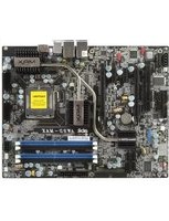

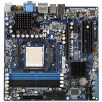
- Socket 478 System Board User's Manual
- Copyright and Warranty Notice
- Table Of Contents
- Chapter 1. Introduction 1-1
- Chapter 2. Hardware Setup 2-1
- Chapter 3. BIOS Setup 3-1
- VT7 快速安装指引
- YcTaHOBKa MaTePnHcKoI IaTbI B KOpNyc
- YcTaHOBKa MoJyJeIiMaHTN
- Pa3bembl, IpeekJIOUaTeJIH n aIaIITepbl
- IoiKJIIOUeHHe Ka6eJeI INTahHn K pa3bEmam ATX12V
- Hactpoika BIOS
- 1-1. Features & Specifications
- CPU
- Chipset
- Memory
- AGP
- Serial ATA 150 RAID
- Audio
- LAN
- System BIOS
- Internal I/O Connectors
- Back Panel I/O
- ABIT Engineered
- Miscellaneous
- 1-2. Layout Diagram
- Chapter 2. Hardware Setup
- 2-1. Install The Motherboard
- 2-2. Install Pentium® 4 CPU and Heatsink Supporting-Base
- 2-3. Install System Memory
- 2-4. Connectors, Headers and Switches
- (1).ATX Power Input Connectors
- (2). FAN Connectors
- (3). CMOS Memory Clearing Header
- (4). Wake-up Header
- PS2-PWR1:
- USB-PWR1:
- USB-PWR2:
- (5). Front Panel Switches & Indicators Headers
- (6). Additional USB Port Headers
- (7). Internal Audio Connectors
- (8). Accelerated Graphics Port Slot
- (9). Floppy Disk Drive Connector
- (10). IDE Connectors
- (11). Serial ATA Connectors
- (12). System Management Bus Headers
- (13). Status Indicator
- (14). Back Panel Connectors
- AUDIO2:
- Chapter 3. BIOS Setup
- PRESS DEL TO ENTER SETUP
- 3-1. SoftMenu Setup
- Brand Name:
- Frequency:
- Cache Size:
- CPU Operating Speed:
- User Define:
- \* CPU FSB Clock (MHz):
- \* Multiplier Factor:
- * Estimated new CPU clock:
- DRAM/PCI Ratio:
- * AGP Ratio (CPU:AGP:PCI):
- * New CPU/DDR/AGP/PCI Clk:
- Voltages Control:
- CPU Core Voltage:
- DRAM Voltage:
- * AGP Voltage:
- 3-2. Standard CMOS Features
- Date (mm:dd:yy):
- Time (hh:mm:ss):
- IDE Channel 0 Master/Slave and IDE Channel 1 Master/Slave:
- IDE HDD Auto-Detection:
- Base Memory:
- Extended Memory:
- Total Memory:
- 3-3. Advanced BIOS Features
- Hyper-Threading Technology
- Quick Power On Self Test:
- Hard Disk Boot Priority:
- * Bootable Add-in Device:
- HDD Change Message:
- First Boot Device / Second Boot Device / Third Boot Device / Boot Other Device:
- Swap Floppy Drive:
- Boot Up Floppy Seek:
- Boot Up NumLock Status:
- Security Option:
- APIC Mode:
- MPS Version Control For OS:
- OS Select For DRAM >64MB
- Report No FDD For WIN 95:
- Disable Unused PCI Clock:
- Intel OnScreen Branding:
- 3-4. Advanced Chipset Features
- DRAM Clock/Drive Control:
- DRAM Timing:
- DRAM BUS Selection:
- DRAM Command Rate:
- Back to Advanced Chipset Features Setup Menu:
- AGP & P2P Bridge Control:
- AGP Aperture Size:
- AGP 3.0 Mode:
- AGP Driving Control:
- * AGP Driving Value:
- AGP Fast Write:
- AGP Master 1 WS Write:
- AGP Master 1 WS Read:
- AGP 3.0 Calibration cycle:
- CPU & PCI Bus Control:
- PCI Master 0 WS Write:
- VLink 8X Support:
- System BIOS Cacheable:
- Top Performance:
- Init Display First:
- 3-5. Integrated Peripherals
- VIA OnChip IDE Device:
- SATA RAID ROM:
- IDE Bus Master:
- IDE Prefetch Mode:
- Onboard IDE-1 Controller:
- Onboard IDE-2 Controller:
- Back to Integrated Peripherals Setup Menu:
- VIA OnChip PCI Device:
- OnChip Audio Controller:
- OnChip LAN Controller:
- \* OnChip LAN Boot ROM:
- OnChip USB Controller:
- \* USB 2.0 Controller:
- \* USB Keyboard Support:
- * USB Mouse Support:
- SuperIO Device:
- Onboard FDC Controller:
- Onboard Serial Port 1:
- Onboard Parallel Port:
- * Parallel Port Mode:
- EPP Mode Select:
- ECP Mode Use DMA:
- 3-6. Power Management Setup
- ACPI Suspend Type:
- Power Button Function:
- Run VGABIOS if S3 Resume:
- Restore On AC Power Loss:
- IRQ/Event Activity Detect:
- Power On Function:
- Hot Key Power ON:
- * KB Power ON Password:
- * Power Button Lock:
- \* Mouse Power ON:
- Resume by OnChip USB:
- Wake-Up by PME# of PCI:
- Resume by Ring:
- Wakeup by Alarm:
- \* Date (of Month) Alarm:
- * Time (hh:mm:ss) Alarm:
- 3-7. PnP/PCI Configurations
- Resources Controlled By:
- * IRQ Resources:
- Back to PnP/PCI Configurations Setup Menu:
- PCI/VGA Palette Snoop:
- Allocate IRQ To Video:
- Allocate IRQ To USB:
- PCI Latency Timer(CLK):
- PIRQ_0 Use IRQ No. ~PIRQ_3 Use IRQ No.:
- NOTE:
- 3-8. PC Health Status
- Shutdown Temperature:
- CPU Warning Temperature:
- FAN Fail Alarm Selectable:
- Shutdown When CPU FAN Fail:
- CPU FanEQ Speed Control:
- Active Temperature:
- All Voltages, Fans Speed and Thermal Monitoring:
- 3-9. Load Fail-Safe Defaults
- 3-10. Load Optimized Defaults
- 3-11. Set Password
- 3-12. Save & Exit Setup
- 3-13. Exit Without Saving
- Appendix A. Install VIA 4-in-1 Driver
- Click [Next].
- Click [Yes].
- Click [Next].
- Click [Next].
- Click [Next].
- Click [Next].
- Appendix B. Install Audio Driver
- Appendix C. Install LAN Driver
- Appendix D. Install VIA USB 2.0 Driver
- Click [Yes].
- Click [Yes].
- Click [Yes].
- Click [OK].
- Click [Print to File].
- Click [OK].
- Appendix E. Install Serial ATA RAID Driver
- Click [Next].
- Appendix F. ABIT EQ (The Hardware Doctor Utility)
- Appendix G. FlashMenu (BIOS Update Utility)
- Click [Finish] to complete setup.
- Appendix H. Troubleshooting (Need Assistance?)
- Q & A:
- Q: How can I get a quick response to my request for technical support?
- Example 1:
- Example 2:
- Main instructions:
- Technical Support Form
- Appendix I. How to Get Technical Support
Brand : ABIT
Model : VT7
Category : Motherboard