
SI7 - Motherboard ABIT - Free user manual and instructions
Find the device manual for free SI7 ABIT in PDF.

| Product Type | Motherboard |
| Brand | ABIT |
| Model | SI7 |
| Processor Socket | Socket 478 (ZIF) |
| Supported Processors | Intel Pentium 4 |
| Memory Type | RIMM (232 pins) |
| Number of Memory Slots | 2 |
| Minimum Memory | 128 MB |
| Maximum Memory | 2 GB |
| Power Connector | ATX12V |
| Form Factor | ATX |
| Cooling | Fan and heat sink for processor |
| Installation | Quick installation guide included |
| BIOS Configuration | Via the BIOS menu at startup |
| Maintenance | Regularly clean dust with a soft, dry cloth |
| Safety | Avoid short circuits by using insulating standoffs |
| Spare Parts | Available from the manufacturer or authorized dealers |
| Repairability | Repair by a qualified technician recommended |
Frequently Asked Questions - SI7 ABIT
User questions about SI7 ABIT
0 question about this device. Answer the ones you know or ask your own.
Ask a new question about this device
Download the instructions for your Motherboard in PDF format for free! Find your manual SI7 - ABIT and take your electronic device back in hand. On this page are published all the documents necessary for the use of your device. SI7 by ABIT.
USER MANUAL SI7 ABIT
Copyright and Warranty Notice
The information in this document is subject to change without notice and does not represent a commitment on part of the vendor, who assumes no liability or responsibility for any errors that may appear in this manual.
No warranty or representation, either expressed or implied, is made with respect to the quality, accuracy or fitness for any particular part of this document. In no event shall the manufacturer be liable for direct, indirect, special, incidental or consequential damages arising from any defect or error in this manual or product.
Product names appearing in this manual are for identification purpose only and trademarks and product names or brand names appearing in this document are the property of their respective owners.
This document contains materials protected under International Copyright Laws. All rights reserved. No part of this manual may be reproduced, transmitted or transcribed without the expressed written permission of the manufacturer and authors of this manual.
If you do not properly set the motherboard settings, causing the motherboard to malfunction or fail, we cannot guarantee any responsibility.
Table Of Contents
SI7系列快速安装指引 1
Chapter 2. Hardware Setup 2-1
2-1. Install The Motherboard.. 2-1
2-2. Install Pentium® 4 CPU and Heatsink Supporting-Base. 2-2
2-3. Install System Memory 2-3
2-4. Connectors, Headers and Switches 2-5
(1).ATX Power Input Connectors [ATXPWR1,ATX12V1] 2-5
(2). FAN Connectors [CPUFAN1, SYSFAN1, AUXFAN1] 2-6
(3). CMOS Memory Clearing Header [CCMOS1] 2-7
(4). Front Panel Audio Connection Header [FP-AUDIO1]................................2-8
(5). Additional USB Port Headers [FP-USB1, FP-USB2] 2-9
(6). Additional IEEE1394 Port Headers [FP-1394-1, FP-1394-2].....2-10
(7). Front Panel Switches & Indicators Headers [FPIO1] 2-11
(8). System Management Bus Header [SMB1] 2-12
(9). Internal Audio Connectors [CD1, AUX1] 2-12
(10). Accelerated Graphics Port Slot [AGP1] 2-13
(11). Floppy Disk Drive Connector [FDC1] 2-14
(12). IDE Connectors [IDE1, IDE2]. 2-15
(13). Serial ATA Connectors [SATA1, SATA2] 2-16
(14). POST Code Display [U32] 2-17
(15). Onboard Switches [FORWARD, BACK, PS_ON, RESET]......2-20
(16). Status Indicators [D17, D14, D15, D18]. 2-21
(17). Back Panel Connectors [KM1, LPT1, COM1, COM2, OPT-OUT1, AUDIO01, AUDIO02, LAN, USB1]. 2-22
Chapter 3. BIOS Setup 3-1
3-1. SoftMenu Setup Features 3-2
3-2. Standard CMOS Features 3-4
3-3. Advanced BIOS Features 3-6
3-4. Advanced Chipset Features.. 3-8
3-5. Power Management Features 3-10
3-6. PnP/PCI Configurations 3-13
3-7. Integrated Peripherals 3-16
3-8. PC Health Status 3-21
3-9. Set Password 3-22
3-10. Load Optimized Defaults 3-22
3-11. Load Fail-Safe Defaults 3-22
3-12. Save & Exit Setup 3-22
3-13. Exit Without Saving 3-22
Appendix A. Install SiS Chipset Driver. 4
Appendix B. Install SiS IDE Driver
Appendix C. Install Audio Driver..
Appendix D. Install LAN Driver....
Appendix E. Install SiS USB 2.0 Driver..
Appendix F. Install Serial ATA RAID Driver..
Appendix G. BIOS Update Guide.. .G-1
Appendix H. Hardware Monitoring (The Winbond Hardware Doctor Utility)...H-1
Appendix I. Installation Guide for Suspend to RAM 1-1
Appendix J. Troubleshooting (Need Assistance?)............................................J-1
Appendix K. How to Get Technical Support.
SI7 系列快速安装指引
BHHMaHHe: Ipi HcIOJIb3OBAHH KOpIyCa cIeIHaJIbHO IpEJaHaNeHHoro JIa Pentium 4 o6paTHTe BHHMaHHe Ha pacIOJIIOKeHHe MeTaJIINueckHX BCtABOK HJn paIIOpOK, ecJH OHy Uke yCTaHOBJIeHb B KOpIyC. He JoIpyCKaIte KOHTaTa MeTaJIINueckHX BCtABOK HJN paIIOpOK c IpoBOdHIKKAMH HJN DeTaJIaMn IIeATHOI IIaTbI.
- CmecHTHe pbyar rHe3Ja Ipoeeccopa B cTOpHy ot rHe3Ja, a 3aTeM IOBepHnTe erO BBepx Ha 90 rpaJycoB. BCTabYe Ipoeeccop, opeHTnpoBaB erO haJIeKaIIM OhpazOM. YcTaHaJIbHBAI Ipoeeccop, He IIpHKJaIbIbAte Hye3MePbHbX yCJIIH. Ero yctaHObKa BO3MOKHa TOJIbKO B OJHMO IIOJKeHH. IIpnKab Ipoieccop CBepxO, ONyCTHe pbyar rHe3Ja.
3.ПOMeCTHHe paIHaTOp IIIOscKoI CTOpHOI Ha IpoIeCCop TAK, YTO6bI IpoIeCCop 6bJI IOJIHOCTbIO 3aKpbIIT.
4.ПомecHTe ПнЖMHNYO КьИКу paДиATopaHa paДиATop.Bce YeTbIpe ΦHKcaTopa IIO O6EHM cTOPOHAM IIpHJKMHOI KpbIIKNДОЛЖHbI HAXOДNTbcra Ha ypoBHe KpeIeKHBIX OTBepCTHn. - p h K M H T e BHH3 HK CHPyIOUIHE 3aKHMbI IIO O6eHM CTOPOHAM IIpHKMHHO KpbIIHK IN IOHX HK caIHIN B KpeIeXHOM OCHOBAHHH.CJIeIHTe 3a HaIIpaJIeHHeM,B KOtOpOM BbI pHKHMaTe 3aKHMbl.
- KpbHka H oCHOBaHHe OJIKNbI 6bITb HAJIeKHO cKeIIeHbI, fHKcHpy paHaHTop.
BHHMaHHe: He 3a6yIbTe yctaHOBHT bIJI IpoIeCCoppa HaJIeKaIyIu YacToTy IIHHbI MHOJKTeJIb.
YcTaHOBKa MaTePnHckoI IaTbI B KOpNvC
IocJIe yctAHOBKN IIpoIIeCCopa Ha MaTePHNCKyIO IJIaTy MOKHO HAuHHaTHb ycTaHOBKY MaTePHNCKOIIaTb B KopIyc. BoJIbIIaA qacTb KOpIycob O6OpYIOBaHa OCHOBAHEm, B KOTOpOM IIpoJEAHbMOHTaJHbE OTBepCTHn, KOtOpBIE IO3BOJIaHOT HAnEJKHO 3aKpeINITb MaTePHNCKyIO IJIaTy HIpEIoTbPaHTbKOPOTKHe 3aMbIkaHH. IJIa KpeIJIeHHMaTePHNCKo IJIaTb K OCHOBAHIO HCIOJIb3yOTc BHNbI bI pOKJIaIKH.
UcTaHOBka MoVJIeI NaMHTN
Ha IIaTe HmeeTcra 2 232-KoHTaKTbIx rHe3Ja
pacIIHpeHHRA RIMM IJIpaMArTH. MHHMaJIbHbI
06bem IaMArTH paBeH 128 M6aIT,
MAKCHMaJIbHbI O6bEm paBeH 2 76aIT RIMM.
UcTaHOBHTe MoJyIb IaMAYTH RIMMBrHe3IO paIHHpeHnKaIOka3aHOHa pHCyHKe. O6paTHTe BHHMaHHe, YTO MoJyIb fHKcHypETCR B rHe3JIe.TaKHM 06pa3OM,rapAHThpyETc eHNCTBeHHO BO3MOxKnbl CnOCo6 yCTaHOBKN MoJyIRMM.BcTaBtBEMoJyIB RIMMBr He3IO RIMM; H y6eJIHTecB, TOT MOJyJB HaJeKHO yCTaHOBJIEN B rHe3IO RIMM.
Pa3bEmbl, HepeKJIooYaTeHn H aIaIITepbl
BHytpn KOpIpyca KOMIIbHOTepa Heo6xOJHMO paCIOIOXeHb HeCKOJIbKO Ka6eIe H BHIOK, KOtOpBle Heo6xOJHMO IOKJIIOUHTb. O6bIyHO 3TN Ka6eJIIN POJKIJOuHaOTcK Pa3bEAMam, paCIOIOXeHHBM Ha MaTePnIHcKoi IIATE. PInp IOJIKIOHeHHN IO6Oro Ka6eJIaHEo6xOJHMO o6paIIaTb BHIMAHHe Ha PaCIOIOXeHHe IepBOrO KOHTAKTa pa3bEma. IepOC6bIX IeJIe MORYT IOTpe6OBaTbc CIEIIHaJIbHBe aAdIaRb, HanIpMeR, aAdIaIte SCSI, aAdIaIte AGP n.t.. PInp yCTaHOBe aAdIaTePob B rHe3Ja MaTePHNckoi IIATb 3AkpeIInTe IH Na 3aIDHe N pAHeJI c NMOIIIbO BVHTOB.
3a 6oJIe eIIOJIO6Hoi HnΦOpMaIHeN O6paIIaJIteBc K IOJIHOmy pyKOBOICTBy IOJIb3OBaTeJIa.
IoiKJIIOUeHHe Ka6eJeI IHTaHHN K pa3bEmAM ATX12V
O6paTHHe BHHMaHHe, pa3bEm 6Ioka IIITaHnA HT X He06XoIMMo BCTaBHTb B pa3bEm ATX12V do yInopa, YTO6bI OecIIeHTb HaeJxHoe CoEHNHeHHe.
Hacrpoika BIOS
1-1. Features & Specifications
1. CPU
Supports Intel Pentium 4 socket 478 processor with 400MHz / 533MHz System Data Bus
Supports Intel Hyper-Threading Technology
2. Chipset
SiR658 ^+ SiS963
Supports Hi-Speed Universal Serial Bus (USB 2.0)
Supports Ultra ATA/133/100/66/33 mode
3. Memory
Supports 2x 32-bit RIMM PC1200/PC1066/PC800 Direct RDRAM (2GB MAX)
Supports configurable ECC function
4. AGP
- Accelerated Graphics Port connector supports AGP 8X/4X Interface (0.8V/1.5V)
5. LAN
- Onboard Broadcom Gigabit PCI Ethernet Controller (For SI7-G)
- Onboard 10/100M PCI Fast Ethernet Controller (For SI7)
6. Serial ATA 150
- Onboard Silicon Image Serial ATA PCI Controller
Support 2 ports SATA 150 (1.5G bps)
7. Media XP (Optional)
Supports card reader function for Memory Stick, Secure Digital and Type I/II CompactFlash
Supports Wireless Remote Control and S/PDIF Out / Mic In / Headphone Out / USB 2.0 / IEEE 1394
8. USB 2.0
- 6x USB 2.0 ports support 480Mb / s data transfer rate
9.IEEE1394
- 2x IEEE 1394 ports support 400/200/100Mb/s data transfer rate
10. Audio
- Onboard RealTek ALC650 6-Channel AC 97 CODEC
Professional digital audio interface supports 24-bit S/PDIF Out
11. System BIOS
- SoftMenu™ Technology to set CPU parameters
Supports Plug-and-Play (PNP)
Supports Advanced Configuration Power Interface (ACPI)
Supports Desktop Management Interface (DMI)
AMI BIOS
12. Internal I/O Connectors
1x AGP slot
5x PCI slots
1x Floppy port supports up to 2.88MB
2x Ultra ATA/133/100/66/33 connectors
2x Serial ATA 150 connectors
- 2x USB headers
2x IEEE 1394 headers
1x CD-IN, 1x AUX-IN header
13. Back Panel I/O
1x PS/2 Keyboard, 1x PS/2 mouse
- 2x Serial port connectors, 1x Parallel port connector
1x S/PDIF Out connector
- AUDIO1 connector (Rear-Left / Rear-Right, Center/Subwoofer)
- AUDIO2 connector (Mic-In, Line-In, Front-Left/Right)
2x USB, 1x RJ-45 LAN Connector
14. Miscellaneous
ATX form factor
- Hardware Monitoring - including Fan Speed, Voltages, CPU and system temperature
Supports Wake Up by LAN, Modem Ring, RTC Alarm, Keyboard and Mouse Power On
Supports STR (Suspend to RAM)
- Onboard debug card design with 7-segment display
15. Order Information
| Model | Features |
| S17 | SATA, 10/100M LAN |
| S17-G | SATA, Gigabit LAN |
- Supports Wake On LAN, Modem, but your ATX power supply 5V standby power must be able to provide at least a 720mA current capacity. Otherwise, the functions may not work normally.
- This motherboard supports the standard bus speeds of 133/100/66MHz that are used by specific PCI, processor and chipset specifications. Exceeding these standard bus speeds is not guaranteed due to the specific component specifications.
- The Serial ATA controller only supports Ultra DMA/ATA100 or higher hard drive. Do not use hard drives under this specification, or it won't work.
- Specifications and information contained herein are subject to change without notice.
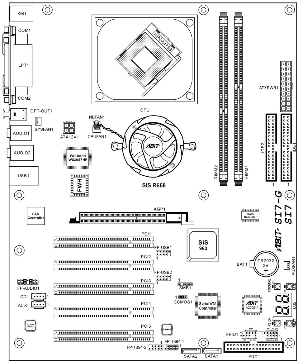
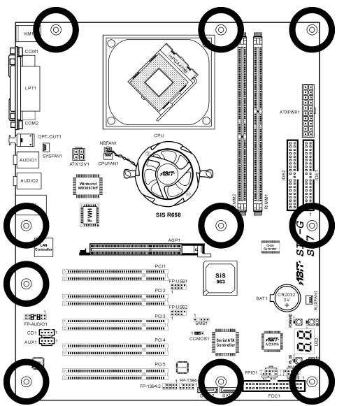
1-2. Layout Diagram

Chapter 2. Hardware Setup
Before the Installation: Turn off the power supply switch (fully turn off the +5V standby power), or disconnect the power cord before installing or unplugging any connectors or add-on cards. Failing to do so may cause the motherboard components or add-on cards to malfunction or damaged.
2-1. Install The Motherboard
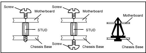
Most computer chassis have a base with many mounting holes to allow motherboard to be securely attached on and at the same time, prevented from short circuits. There are two ways to attach the motherboard to the chassis base:
- Use with studs
- Or use with spacers
In principle, the best way to attach the board is to use with studs. Only if you are unable to do this should you attach the board with spacers. Line up the holes on the board with the mounting holes on the chassis. If the holes line up and there are screw holes, you can attach the board with studs. If the holes line up and there are only slots, you can only attach with spacers. Take the tip of the spacers and insert them into the slots. After doing this to all the slots, you can slide the board into position aligned with slots. After the board has been positioned, check to make sure everything is OK before putting the chassis back on.
ATTENTION: To prevent shorting the PCB circuit, please REMOVE the metal studs or spacers if they are already fastened on the chassis base and are without mounting-holes on the motherboard to align with.

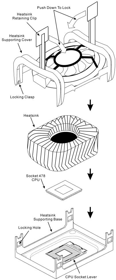
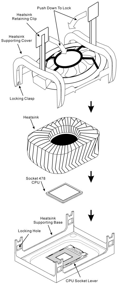
2-2. Install Pentium® 4 CPU and Heatsink Supporting-Base
This motherboard provides a ZIF (Zero Insertion Force) Socket 478 to install Intel Pentium CPU. The CPU you bought should have a kit of heatsink and cooling fan along with. If that's not the case, buy one specially designed for Pentium 4 Socket 478.
- Locate the Socket 478. Fasten the heatsink supporting-base onto the motherboard.
ATTENTION: If you are using chassis specially designed for Pentium® 4, please pay attention to the location of metal studs or spacers if they are already installed on the chassis. Be careful not let the metal studs or spacers contact the printed circuit wire or parts on the PCB.
- Pull the CPU socket lever sideways away from the socket and then upwards to 90 degree. Insert the CPU with the correct orientation. Do not use extra force to insert CPU; it only fit in one orientation. Closing down the socket lever while holding down the CPU.
- Put the heatsink faces down onto the CPU until it completely covers the CPU.
- Put the heatsink supporting-cover onto the heatsink. Make sure all the four locking clasp at each side of the supporting cover reach in the locking holes.
- Push down the retaining clip at both sides of the supporting cover to lock up together with the supporting base. Watch out the direction for pushing down the clip.
- The heatsink supporting cover and base should now firmly locking up with each other with the heatsink inside.
ATTENTION: Do not forget to set the correct bus frequency and multiple for your processor.
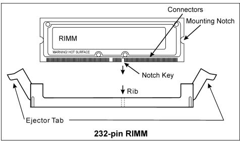
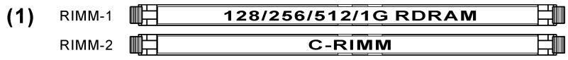
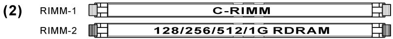
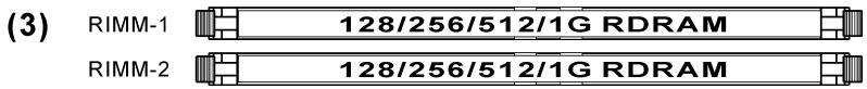
2-3. Install System Memory
This motherboard provides two 232-pin 32-bit RIMM (Rambus Inline Memory Modules) slots for PC1200/PC1066/PC800 Direct RDRAM.
ATTENTION: The PC1066 RIMM modules require CPU of 533MHz FSB only. Do not use PC1066 modules with CPU of 400MHz FSB.
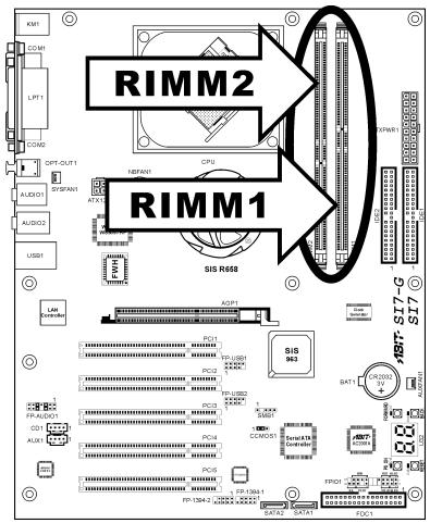
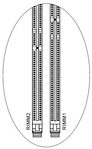
Table 2-1. Valid Memory Configurations
| Bank | Memory Module | Total Memory |
| Bank 0, 1 (RIMM1) | 128, 256, 512MB, 1GB | 128MB ~ 1GB |
| Bank 2, 3 (RIMM2) | 128, 256, 512MB, 1GB | 128MB ~ 1GB |
| Total System Memory | 128MB ~ 2GB | |
NOTE: RIMM modules are limited to a total combination of 24 chip devices only.
The RIMM slots must be fully installed with RIMM modules to avoid breaking the signal lines. To assure the electrical integrity of the Rambus interface when installing only one RIMM module, a C-RIMM is therefore necessary to complete the signal lines.
The diagram below shows the possible combination of RDRAM installation.
NOTE: No hardware or BIOS setup required after adding or removing memory modules.
ATTENTION: Static electricity can damage the electronic components of the computer or optional boards. Before starting these procedures, ensure that you are discharged of static electricity by touching a grounded metal object briefly.
Power off the computer and unplug the AC power cord before installing or removing memory modules.
- Locate the RIMM slot on the board.
- Hold two edges of the RIMM module carefully, keep away of touching its connectors.
- Align the notch key on the module with the rib on the slot.
- Firmly press the module into the slots until the ejector tabs at both sides of the slot automatically snaps into the mounting notch.
Do not force the RIMM module in with extra force as the RIMM module only fit in one direction.
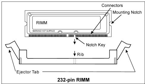
- To remove the RIMM modules, push the two ejector tabs on the slot outward simultaneously, and then pull out the RIMM module.
WARNING: RIMM modules become extremely hot during operation. Don't touch the heat spreader before it cools down.
2-4. Connectors, Headers and Switches
Here we will show you all of the connectors, headers and switches, and how to connect them. Please read the entire section for necessary information before attempting to finish all the hardware installation inside the computer chassis. A complete enlarged layout diagram is shown in Chapter 1 for all the position of connectors and headers on the board that you may refer to.
WARNING: Always power off the computer and unplug the AC power cord before adding or removing any peripheral or component. Failing to so may cause severe damage to your motherboard and/or peripherals. Plug in the AC power cord only after you have carefully checked everything.
(1).ATX Power Input Connectors [ATXPWR1, ATX12V1]
The Pentium 4 requires a power supplier different from the regular one. It's a newly designed ATX12V power with 300W , 20A + 5VDC capacity at least for heavily loaded system, and 720mA + 5VSB at least for supporting Wake-On-LAN feature.
![ABIT SI7 - (1).ATX Power Input Connectors [ATXPWR1, ATX12V1] - 1](/content/2025/01/174582/images/50e44d395a763ef5fb474da2c28235caa6f3e31bc9d185222be3b31ffd324f64.jpg)
![ABIT SI7 - (1).ATX Power Input Connectors [ATXPWR1, ATX12V1] - 2](/content/2025/01/174582/images/e5dbcb298b43f7c0dc12e13843de4f7d71f0b7aab6e1df64d1d4ac8339016c30.jpg)
(2). FAN Connectors [CPUFAN1, SYSFAN1, AUXFAN1]
These 3-pin connectors each provide power to the cooling fans installed in your system.
The CPU must be kept cool by using a powerful fan with heatsink. The system is capable of monitoring the speed of the CPU fan.
- CPUFAN1: CPU Fan
- SYSFAN1: System Fan
AUXFAN1: Auxiliary Fan
WARNING: These fan connectors are not jumpers. DO NOT place jumper caps on these connectors.
![ABIT SI7 - (2). FAN Connectors [CPUFAN1, SYSFAN1, AUXFAN1] - 1](/content/2025/01/174582/images/18fbecb9536e9fadc4caa88d56b35805f8014a5165d2db13cb5551bcabc40088.jpg)
![ABIT SI7 - (2). FAN Connectors [CPUFAN1, SYSFAN1, AUXFAN1] - 2](/content/2025/01/174582/images/35d8b55ecedd89d0c55411b57cbc293b0441c5fb9ff8de6430d372714385e86c.jpg)
(3). CMOS Memory Clearing Header [CCMOS1]
This header uses a jumper cap to clear the CMOS memory.
Pin 1-2 shorted (default): Normal operation.
Pin 2-3 shorted: Clear CMOS memory.
![ABIT SI7 - (3). CMOS Memory Clearing Header [CCMOS1] - 1](/content/2025/01/174582/images/bed3c546a016c0834b2fe25eb927ada9cf76e2cbe0c8c6800e55fa56e0cf684d.jpg)
![ABIT SI7 - (3). CMOS Memory Clearing Header [CCMOS1] - 2](/content/2025/01/174582/images/b0042da9c816e30145522ffe834a5fd94a6f318cdf26ada1a57017699f53e300.jpg)
WARNING: Turn the power off first (including the +5V standby power) before clearing the CMOS memory. Failing to do so may cause your system to work abnormally or malfunction.
(4). Front Panel Audio Connection Header [FP-AUDIO1]
This header provides the connection to audio connector at front panel (with optional ABIT Media XP).
- To use the audio connector at front panel, remove all the jumpers on this header, and then connect to front panel by the extension cable provided with the chassis.
- To use the audio connector at rear panel, disconnect the extension cable, attach the jumpers back at pin 5-6, and pin 9-10 (default setting).
![ABIT SI7 - (4). Front Panel Audio Connection Header [FP-AUDIO1] - 1](/content/2025/01/174582/images/afc6ff7b8f546eb6065cb82ea2462e4a4c47b4136080eeb94897a515a1e10951.jpg)
| FP-AUDIO1 | Pin | Pin Assignment | Pin | Pin Assignment |
| 1 | Audio Mic. | 2 | Ground | |
| 3 | Audio Mic. Bias | 4 | VCC | |
| 5 | Speaker Out Right Channel | 6 | Speaker Out Right Channel Return | |
| 7 | X | 8 | NC | |
| 9 | Speaker Out Left Channel | 10 | Speaker Out Left Channel Return | |
| 11 | Ground | 12 | S/PDIF In | |
| 13 | VCC | 14 | S/PDIF Out |
(5). Additional USB Port Headers [FP-USB1, FP-USB2]
These headers each provide 2 additional USB 2.0 ports connection through an USB cable designed for USB 2.0 specifications.
![ABIT SI7 - (5). Additional USB Port Headers [FP-USB1, FP-USB2] - 1](/content/2025/01/174582/images/c02b08819d6e7c86d186d4f4a2eb2c3e69476ec159b2affce17007f72047178b.jpg)
| 2 4 6 8 10 1 3 5 7 9 FP-USB1 FP-USB2 | Pin | Pin Assignment | Pin | Pin Assignment |
| 1 | VCC | 2 | VCC | |
| 3 | Data0 - | 4 | Data1 - | |
| 5 | Data0 + | 6 | Data1 + | |
| 7 | Ground | 8 | Ground | |
| 9 | NC | 10 | NC |
![ABIT SI7 - (5). Additional USB Port Headers [FP-USB1, FP-USB2] - 2](/content/2025/01/174582/images/f671591a2982e6eb10753b231cc6f3eabfde4c0c9e214ca9b25f20de94f22814.jpg)
USB Header
(6). Additional IEEE1394 Port Headers [FP-1394-1, FP-1394-2]
These headers each provide 1 additional IEEE1394 port connection through an extension cable and bracket.
![ABIT SI7 - (6). Additional IEEE1394 Port Headers [FP-1394-1, FP-1394-2] - 1](/content/2025/01/174582/images/3abbf175756c9240942bf088b61434ed92da58af84abe965463c51f90fba853c.jpg)
| 9 7 5 3 1 10 8 6 4 2 FP-1394-1 FP-1394-2 | Pin | Pin Assignment | Pin | Pin Assignment |
| 1 | TPA0 + | 2 | TPA0 - | |
| 3 | GND | 4 | GND | |
| 5 | TPB0 + | 6 | TPB0 - | |
| 7 | +12V | 8 | +12V | |
| 9 | NC | 10 | GND |
![ABIT SI7 - (6). Additional IEEE1394 Port Headers [FP-1394-1, FP-1394-2] - 2](/content/2025/01/174582/images/b5a55df56e312abf96cdd60534e1e36fd52866c90251b7dbd6cc0c31c37b64b5.jpg)
IEEE1394 Header
(7). Front Panel Switches & Indicators Headers [FPIO1]
This header is used for connecting switches and LED indicators on the chassis front panel.
Watch the power LED pin position and orientation. The mark "+" align to the pin in the figure below stands for positive polarity for the LED connection. Please pay attention to connect these headers. A wrong orientation will only cause the LED not lighting, but a wrong connection of the switches could cause system malfunction.
![ABIT SI7 - (7). Front Panel Switches & Indicators Headers [FPIO1] - 1](/content/2025/01/174582/images/ac2a8acf447652a1f4c177d147c90816c9c8aad17c3fdc3b6a8c39340d37057c.jpg)
![ABIT SI7 - (7). Front Panel Switches & Indicators Headers [FPIO1] - 2](/content/2025/01/174582/images/f0a542636a635fd03a04ef6a62e7fe0be2971f20f8844f962e4189bb9c7fc445.jpg)
- HLED (Pin 1, 3): Connects to the HDD LED cable of chassis front panel.
- RST (Pin 5, 7): Connects to the Reset Switch cable of chassis front panel.
- SPK (Pin 15, 17, 19, 21): Connects to the System Speaker cable of chassis.
- SLED (Pin 2, 4): Connects to the Suspend LED cable (if there is one) of chassis front panel.
- PWR-ON (Pin 6, 8): Connects to the Power Switch cable of chassis front panel.
- PLED (Pin 16, 18, 20): Connects to the Power LED cable of chassis front panel.
- K/L (Pin 22, 24): Connects to the Keylock cable (if there is one) of chassis front panel.
(8). System Management Bus Header [SMB1]
This header is reserved for system management bus (SM bus). The SM bus is a specific implementation of an I^2C bus. I^2C is a multi-master bus, which means that multiple chips can be connected to the same bus and each one can act as a master by initiating a data transfer. If more than one master simultaneously tries to control the bus, an arbitration procedure decides which master gets priority.
![ABIT SI7 - (8). System Management Bus Header [SMB1] - 1](/content/2025/01/174582/images/685c95660a425668063884b2c91d9b73e8fa93d3c5c5c9a1712672dc51304c7f.jpg)
![ABIT SI7 - (8). System Management Bus Header [SMB1] - 2](/content/2025/01/174582/images/cb6296f881fdefe1622f82fdd4563dd6d607047b8d513cd2d9bb2e43f037edfe.jpg)
(9). Internal Audio Connectors [CD1, AUX1]
These connectors connect to the audio output of internal CD-ROM drive or add-on card.
![ABIT SI7 - (9). Internal Audio Connectors [CD1, AUX1] - 1](/content/2025/01/174582/images/6e1b44f09c93f64e2dced4e66a78b24b92aa8c581aae06132bd065d6bd01ed1e.jpg)
![ABIT SI7 - (9). Internal Audio Connectors [CD1, AUX1] - 2](/content/2025/01/174582/images/dd0cf94ea77cc898a52dcf9bc7219fc60e481d61c9407b30bdf8dfb8a8cfcf5f.jpg)
(10). Accelerated Graphics Port Slot [AGP1]
This slot supports an optional AGP graphics card up to AGP 4X/8X mode. Please refer to our Web site for more information on graphics cards.
ATTENTION: This motherboard does not support 3.3V AGP cards. Use only 1.5V or 0.8V AGP cards.
![ABIT SI7 - (10). Accelerated Graphics Port Slot [AGP1] - 1](/content/2025/01/174582/images/58d5c9ebb80c68742cc1098ae3486c0500a0f545c870771a214529d6ec16f9cf.jpg)
![ABIT SI7 - (10). Accelerated Graphics Port Slot [AGP1] - 2](/content/2025/01/174582/images/e50bb7d79bc24ec7559603ce0d2051c7b7f54cff11fbdd4cb6ca23ad1d769a89.jpg)
(11). Floppy Disk Drive Connector [FDC1]
This connector supports two standard floppy disk drives via a 34-pin 34-conductor ribbon cable.
Connecting the Floppy Disk Drive Cable:
- Install one end of the ribbon cable into the FDC1 connector. The colored edge of the ribbon cable should be aligned with pin-1 of FDC1 connector.
- Install the other end(s) of ribbon cable into the disk drive connector(s). The colored edge of the ribbon cable should be also aligned with pin-1 of disk drive connector. The endmost connector should be attached to the drive designated as Drive A.
![ABIT SI7 - (11). Floppy Disk Drive Connector [FDC1] - 1](/content/2025/01/174582/images/edc92c508f45420ee97bb6503bc579ff7b074a518810fa6cf29a706f0045550f.jpg)
![ABIT SI7 - (11). Floppy Disk Drive Connector [FDC1] - 2](/content/2025/01/174582/images/9755060d5eab2a7531dc730cad0c6f715261c7c9ec01d1b3a9347f75328322a2.jpg)
![ABIT SI7 - (11). Floppy Disk Drive Connector [FDC1] - 3](/content/2025/01/174582/images/dbfc6b52a035c498b34b4aa148a46769dfee1d82dc01b72b9f73f9c79c8fe215.jpg)
(12). IDE Connectors [IDE1, IDE2]
![ABIT SI7 - (11). Floppy Disk Drive Connector [FDC1] - 4](/content/2025/01/174582/images/b60e539dc81d2b068eb24d722e99126da10a6f5630450689f8a2b4f9ab49a8d8.jpg)
![ABIT SI7 - (11). Floppy Disk Drive Connector [FDC1] - 5](/content/2025/01/174582/images/af1fcfd3e8e0700757ac6ff765b0b72ba269b7fdeb17327d9e65ad158cf5023d.jpg)
This motherboard provides two IDE ports to connect up to four IDE drives at Ultra ATA/100 mode by Ultra ATA/66 ribbon cables. Each cable has 40-pin 80-conductor and three connectors, providing two hard drives connection with motherboard. Connect the single end (blue connector) at the longer length of ribbon cable to the IDE port on motherboard, and the other two ends (gray and black connector) at the shorter length of the ribbon cable to the connectors on hard drives.
If you want to connect two hard drives together through one IDE channel, you must configure the second drive to Slave mode after the first Master drive. Please refer to the drives' documentation for jumper settings. The first drive connected to IDE1 is usually referred to as "Primary Master", and the second drive as "Primary Slave". The first drive connected to IDE2 is referred to as "Secondary Master" and the second drive as "Secondary Slave".
Keep away from connecting one legacy slow speed drive, like CD-ROM, together with another hard drive on the same IDE channel; this will drop your integral system performance.
(13). Serial ATA Connectors [SATA1, SATA2]
These two connectors are provided to attach one serial ATA device at each channel through Serial ATA cable. It is also possible to connect legacy IDE hard disk through an optional SERILLEL Converter.
![ABIT SI7 - (13). Serial ATA Connectors [SATA1, SATA2] - 1](/content/2025/01/174582/images/fbc272af1ee10765b6847a570d479555df760306a8ce44d4c9363720019f511d.jpg)
![ABIT SI7 - (13). Serial ATA Connectors [SATA1, SATA2] - 2](/content/2025/01/174582/images/8c0769c45b3c7a060e728ce51c6c8bcb776a5e7e11fc645c914c068def58c6d3.jpg)
![ABIT SI7 - (13). Serial ATA Connectors [SATA1, SATA2] - 3](/content/2025/01/174582/images/7dbf2b6ce53f44972ace39a534494ec9306f9e97f7e0b5b89f967879f552c2b6.jpg)
(14). POST Code Display [U32]
This is an LED device to display the "POST" Code, the acronym of Power On Self Test. The computer will execute the POST action whenever you power on the computer. The POST process is controlled by the BIOS. It is used to detect the status of the computer's main components and peripherals. Each POST Code corresponds to different checkpoints that are also defined by the BIOS in advance. For example, "memory presence test" is an important checkpoint and its POST Code is "C1". When the BIOS execute any POST item, it will write the corresponding POST Code into the address 80h. If the POST passes, the BIOS will process the next POST item and write the next POST Code into the address 80h. If the POST fails, we can check the POST Code in address 80h to find out where the problem lies.
![ABIT SI7 - (14). POST Code Display [U32] - 1](/content/2025/01/174582/images/8bde5092b5e90e7d912f86a5000c87a65c9c3fedcd9fd348b26826fb021eadc9.jpg)
![ABIT SI7 - (14). POST Code Display [U32] - 2](/content/2025/01/174582/images/ac1bbc962d052425b7c49852a17102d9b151e9bb45e8457db3e649f65e9402f4.jpg)
The following table shows the POST Code in detail:
| POST Code | Description |
| CF | Test CMOS R/W functionality |
| C0 | Early chipset initialization: -Disable shadow RAM -Disable L2 cache (socket 7 or below) -Program basic chipset registers |
| C1 | Detect memory -Auto-detection of DRAM size, type and ECC -Auto-detection of L2 cache (socket 7 or below) |
| C3 | Expand compressed BIOS code to DRAM |
| C5 | Call chipset hook to copy BIOS back to E000 & F000 shadow RAM |
| 01 | Expand the Xgroup codes locating in physical address 1000:0 |
| 03 | Initial Superio_Early_Init switch |
| 05 | 1. Blank out screen 2. Clear CMOS error flag |
| 07 | 1. Clear 8042 interface 2. Initialize 8042 self-test |
| 08 | 1. Test special keyboard controller for Winbond 977 series Super I/O chips 2. Enable keyboard interface |
| 0A | 1. Disable PS/2 mouse interface (optional)2. Auto detect ports for keyboard & mouse followed by a port & interface swap (optional)3. Reset keyboard for Winbond 977 series Super I/O chips |
| 0E | Test F000h segment shadow to see whether it is R/W-able or not. If test fails, keep beeping the speaker |
| 10 | Auto detect flash type to load appropriate flash R/W codes into the run time area in F000 for ESCD & DMI support |
| 12 | Use walking 1's algorithm to check out interface in CMOS circuitry. Also set real-time clock power status, and then check for override |
| 14 | Program chipset default values into chipset. Chipset default values are MODBINable by OEM customers |
| 16 | Initial Early Init Onboard Generator switch |
| 18 | Detect CPU information including brand, SMI type (Cyrix or Intel) and CPU level (586 or 686) |
| 1B | Initial interrupts vector table. If no special specified, all H/W interrupts are directed to SPURIOUS_INT_HDLR & S/W interrupts to SPURIOUSsoft_HDLR |
| 1D | Initial EARLY PM INIT switch |
| 1F | Load keyboard matrix (notebook platform) |
| 21 | HPM initialization (notebook platform) |
| 23 | 1. Check validity of RTC value: e.g. a value of 5Ah is an invalid value for RTC minute2. Load CMOS settings into BIOS stack. If CMOS checksum fails, use default value instead3. Prepare BIOS resource map for PCI & PnP use. If ESCD is valid, take into consideration of the ESCD's legacy information4. Onboard clock generator initialization. Disable respective clock resource to empty PCI & DIMM slots5. Early PCI initialization:-Enumerate PCI bus number-Assign memory & I/O resource-Search for a valid VGA device & VGA BIOS, and put it into C000:0 |
| 27 | Initialize INT 09 buffer |
| 29 | 1. Program CPU internal MTRR (P6 & PII) for 0~640K memory address2. Initialize the APIC for Pentium class CPU3. Program early chipset according to CMOS setup. Example: onboard IDE controller4. Measure CPU speed5. Invoke video BIOS |
| 2D | 1. Initialize multi-language2. Put information on screen display, including Award title, CPU type, CPU speed ... |
| 33 | Reset keyboard except Winbond 977 series Super I/O chips |
| 3C | Test 8254 |
| 3E | Test 8259 interrupt mask bits for channel 1 |
| 40 | Test 8259 interrupt mask bits for channel 2 |
| 43 | Test 8259 functionality |
| 47 | Initialize EISA slot |
| 49 | 1. Calculate total memory by testing the last double word of each 64K page2. Program writes allocation for AMD K5 CPU |
| 4E | 1. Program MTRR of M1 CPU 2. Initialize L2 cache for P6 class CPU & program CPU with proper cacheable range 3. Initialize the APIC for P6 class CPU 4. On MP platform, adjust the cacheable range to smaller one in case the cacheable ranges between each CPU are not identical |
| 50 | Initialize USB |
| 52 | Test all memory (clear all extended memory to 0) |
| 55 | Display number of processors (multi-processor platform) |
| 57 | Display PnP logo Early ISA PnP initialization -Assign CSN to every ISA PnP device |
| 59 | Initialize the combined Trend Anti-Virus code |
| 5B | (Optional Feature) Show message for entering AWDFLASH.EXE from FDD (optional) |
| 5D | 1. Initialize Init_Onboard_Super_IO switch 2. Initialize Init_OnbaordAUDIO switch |
| 60 | Okay to enter Setup utility; i.e. not until this POST stage can users enter the CMOS setup utility |
| 65 | Initialize PS/2 Mouse |
| 67 | Prepare memory size information for function call: INT 15h ax=E820h |
| 69 | Turn on L2 cache |
| 6B | Program chipset registers according to items described in Setup & Auto-configuration table |
| 6D | 1. Assign resources to all ISA PnP devices 2. Auto assign ports to onboard COM ports if the corresponding item in Setup is set to “AUTO” |
| 6F | 1. Initialize floppy controller 2. Set up floppy related fields in 40:hardware |
| 73 | (Optional Feature) Enter AWDFLASH.EXE if: -AWDFLASH is found in floppy drive -ALT+F2 is pressed |
| 75 | Detect & install all IDE devices: HDD, LS120, ZIP, CDROM ... |
| 77 | Detect serial ports & parallel ports. |
| 7A | Detect & install co-processor |
| 7F | Switch back to text mode if full screen logo is supported -If errors occur, report errors & wait for keys -If no errors occur or F1 key is pressed to continue: Clear EPA or customization logo |
| 82 | 1. Call chipset power management hook 2. Recover the text fond used by EPA logo (not for full screen logo) 3. If password is set, ask for password |
| 83 | Save all data in stack back to CMOS |
| 84 | Initialize ISA PnP boot devices |
| 85 | 1. USB final Initialization 2. NET PC: Build SYSID structure 3. Switch screen back to text mode 4. Set up ACPI table at top of memory 5. Invoke ISA adapter ROMs 6. Assign IRQs to PCI devices 7. Initialize APM 8. Clear noise of IRQs |
| 93 | Read HDD boot sector information for Trend Anti-Virus code |
| 94 | 1. Enable L2 cache 2. Program boot up speed 3. Chipset final initialization 4. Power management final initialization 5. Clear screen & display summary table 6. Program K6 write allocation 7. Program P6 class write combining |
| 95 | 1. Program daylight saving 2. Update keyboard LED & typematic rate |
| 96 | 1. Build MP table 2. Build & update ESCD 3. Set CMOS century to 20h or 19h 4. Load CMOS time into DOS timer tick 5. Build MSIRQ routing table |
| FF | Boot attempt (INT 19h) |
(15). Onboard Switches [FORWARD, BACK, PS ON, RESET]
FORWARD: Move forward to next code layer of the POST Code Displayer.
- BACK: Move backward to previous code layer of the POST Code Displayer.
PS_ON: Power on the system.
- RESET: Reset the system.
![ABIT SI7 - (15). Onboard Switches [FORWARD, BACK, PS ON, RESET] - 1](/content/2025/01/174582/images/98b274d9e7be972c46513212b40e9925cf2ea6351201ea0be835f90e8a47b78d.jpg)
![ABIT SI7 - (15). Onboard Switches [FORWARD, BACK, PS ON, RESET] - 2](/content/2025/01/174582/images/0c2c07645c7050499dc6da7a4a6523aff3330fa10cd2aed964498d17c0930047.jpg)
(16). Status Indicators [D17, D14, D15, D18]
- D17 (FORWARD): This LED lights up when moving forward to next code layer of the POST Code Displayer.
- D14 (BACK): This LED lights up moving backward to previous code layer of the POST Code Displayer.
D15 (VCC): This LED lights up when the system power is on.
D18 (5VSB): This LED lights up when the power supply is connected with power source.
![ABIT SI7 - (16). Status Indicators [D17, D14, D15, D18] - 1](/content/2025/01/174582/images/2a08e7bcad167219d590ec7556c898a12f7a8553656924cc96bdc1a5eaa3be86.jpg)
![ABIT SI7 - (16). Status Indicators [D17, D14, D15, D18] - 2](/content/2025/01/174582/images/f23c72000cbe3680215d11d72decf7aae01308f81874e86cc92af9dd1f765c0e.jpg)
(17). Back Panel Connectors [KM1, LPT1, COM1, COM2, OPT-OUT1, AUDIO1, AUDIO2, LAN, USB1]
![ABIT SI7 - (16). Status Indicators [D17, D14, D15, D18] - 3](/content/2025/01/174582/images/198aa98f45aee8ba479aadd77bc7ce2cd67dda05c2d3041a61e775b6bab05499.jpg)
- Mouse: Connects to PS/2 mouse.
- Keyboard: Connects to PS/2 keyboard.
- LPT1: Connects to printer or other devices that support this communication protocol.
COM1/COM2: Connects to external modem, mouse or other devices that support this communication protocol. - OPT-OUT1: This connector provides an S/PDIF Out connection through optical fiber to digital multimedia devices.
AUDIO1:
R.L./R.R. (Rear Left / Rear Right): Connects to the rear left and rear right channel in the 5.1 channel audio system.
Cen./Sub. (Center / Subwoofer): Connects to the center and subwoofer channel in the 5.1 channel audio system.
AUDIO2:
Mic In: Connects to the plug from external microphone.
Line In: Connects to the line out from external audio sources.
F.L./F.R. (Front Left / Front Right): Connects to the front left and front right channel in the 5.1-channel or regular 2-channel audio system.
- LAN: Connects to Local Area Network.
- USB1: Connects to USB devices such as scanner, digital speakers, monitor, mouse, keyboard, hub, digital camera, joystick etc.
Chapter 3. BIOS Setup
This motherboard provides a programmable EEPROM that you can update the BIOS utility. The BIOS (Basic Input/Output System) is a program that deals with the basic level of communication between processor and peripherals. Use the BIOS Setup program only when installing motherboard, reconfiguring system, or prompted to "Run Setup". This chapter explains the Setup Utility of BIOS utility.
After powering up the system, the BIOS message appears on the screen, the memory count begins, and then the following message appears on the screen:
Press DEL to run setup
If this message disappears before you respond, restart the system by pressing <Ctrl> + <Alt> + <Del> keys, or by pressing the Reset button on computer chassis. Only when it failed by these two methods can you restart the system by powering it off and then back on.
After pressing <Del> key, the main menu screen appears.
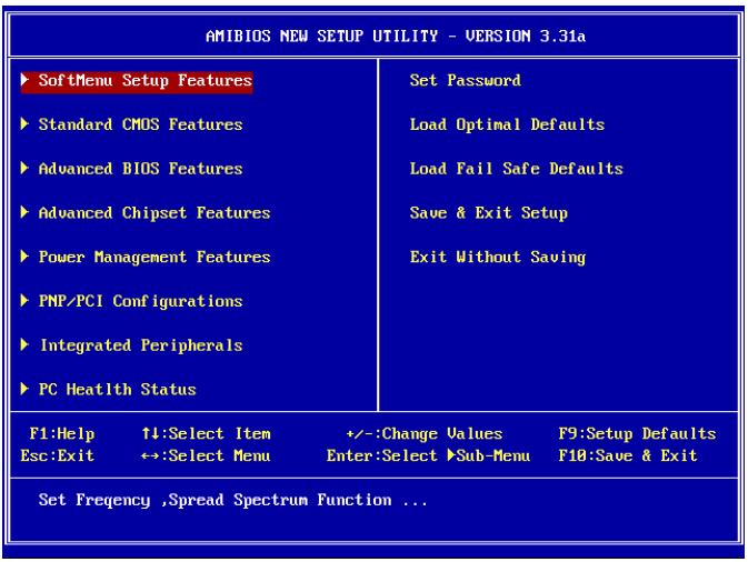
NOTE: In order to increase system stability and performance, our engineering staffs are constantly improving the BIOS menu. The BIOS setup screens and descriptions illustrated in this manual are for your reference only, may not completely match what you see on your screen.
3-1. SoftMenu Setup Features
The SoftMenu utility is ABIT's exclusive and ultimate solution in programming the CPU operating speed. All the parameters regarding CPU FSB speed, multiplier factor, the AGP & PCI clock, and even the CPU core voltage are all available at your fingertips.
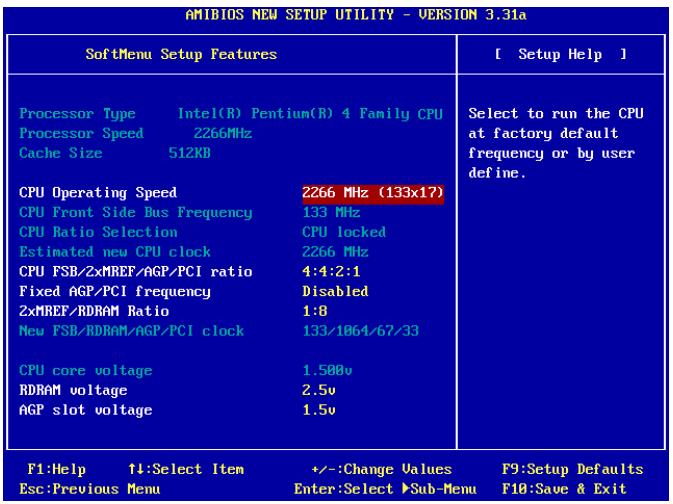
Processor Type:
This item displays the CPU model name, for example: Intel Pentium (R) 4.
Processor Speed:
This item displays the processor speed.
Cache Size:
This item displays the L2 cache size of your CPU.
CPU Operating Speed:
This item displays the CPU operating speed according to your CPU in the format of [FSB] x [multiplier]. You can also select the [User Define] option to enter the manual option.
User Define:
WARNING: The wrong settings of the multiplier and external clock in certain circumstances may cause CPU damage. Setting the working frequency higher than the PCI chipset or processor specs may cause abnormal memory module functioning, system hangs, hard disk drive data lose, abnormal functioning of the VGA card, or abnormal functioning with other add-on cards. Using non-specification settings for your CPU is not the intention of this explanation. These should be used for engineering testing, not for normal applications.
There will be no guaranty for the settings beyond specification, any damage of any component on this motherboard or peripherals result therein is not our responsibility.
CPU Front Side Bus Frequency:
This item selects the FSB frequency for your CPU. The FSB speed above the CPU's standard bus speed is supported but not guaranteed due to its specifications limit.
CPU Ratio Selection:
This item selects the multiplier factors for your CPU if it is not locked.
Estimated new CPU clock:
This item displays the frequency sum up from the previous item [CPU Front Side Bus Frequency] and [CPU Ratio Selection].
CPU FSB/2xMREF/AGP/PCI ratio:
This item selects the ratio for your system components' operation frequency. The estimated new operation frequency for each component will be shown below dynamically. Please keep in mind that you should try to adjust the ratio so that your AGP clock is around 66MHz and your PCI clock is around 33MHz, otherwise, you may encounter abnormal system behavior.
Fixed AGP/PCI frequency:
This option allows you to keep your AGP & PCI clock at some fixed frequency to improve system stability.
2xMREF/RDRAM ratio:
This item displays the ratio of 2xMREF and DRAM. The DRAM frequency can be got by [2xMREF] x [the ratio].
New FSB/DRAM/AGP/PCI clock:
This item displays the frequency sum up from the previous item [CPU FSB/2xMREF/AGP/PCI], [Fixed AGP/PCI frequency], and [2xMREF/RDRAM ratio].
CPU core voltage:
This item selects the core voltage supplied to your CPU. DO NOT raise it too high or it will cause damage to your valuable CPU.
RDRAM voltage:
This item selects the voltage supplied to your RDRAM slot. DO NOT raise it too high or it will cause damage to your valuable RDRAM.
AGP slot voltage:
This item selects the voltage supplied to your AGP slot. Select the correct voltage for your VGA card according to its type.
3-2. Standard CMOS Features
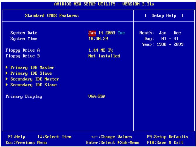
System Date:
This item sets the date you specify (usually the current date) in the format of [Month], [Date], and [Year].
System Time:
This item sets the time you specify (usually the current time) in the format of [Hour], [Minute], and [Second].
Floppy Driver A / Floppy Driver B:
This item sets the type of floppy drives (usually only Drive A) installed.
IDE Primary Master/Slave and IDE Secondary Master/Slave:
Click
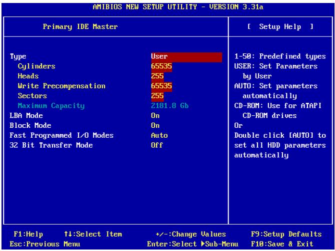
Type:
This item selects the type of your hard disk drives (HDD). Leave this option to its default [AUTO] settings to set all HDD parameters automatically.
NOTE: A newly purchased IDE HDD must be first formatted.
Cylinders:
This item configures the numbers of cylinders.
* Heads:
This item configures the numbers of read/write heads.
* Write Precompensation:
This item displays the number of cylinders at which to change the write timing.
* Sectors:
This item configures the numbers of sectors per track.
Maximum Capacity:
This item displays the drive's maximum capacity as calculated by the BIOS based on the drive information you entered.
LBA (Logical Block Addressing) mode:
This option allows you to select [On] for a hard disk larger than 512 MB capacity under DOS and Windows environment. Select [Off] only when under Netware and UNIX environment.
Block Mode:
This option allows you to select [On] for a hard disk using block mode. The system BIOS will check the hard disk drive for the maximum block size the system can transfer. The block size will depend on the type of hard disk drive. Select [Off] to use standard mode.
Fast Programmed I/O Modes:
This option allows you to select the PIO mode. Select [Auto] will enhance the hard disk performance by optimizing the hard disk timing.
32 Bit Transfer Mode:
This option allows you to select [On] to enable 32bit access to maximize the IDE hard disk data transfer rate.
Primary Display:
This option allows you to select the type video adapter used for the primary system monitor.
3-3. Advanced BIOS Features
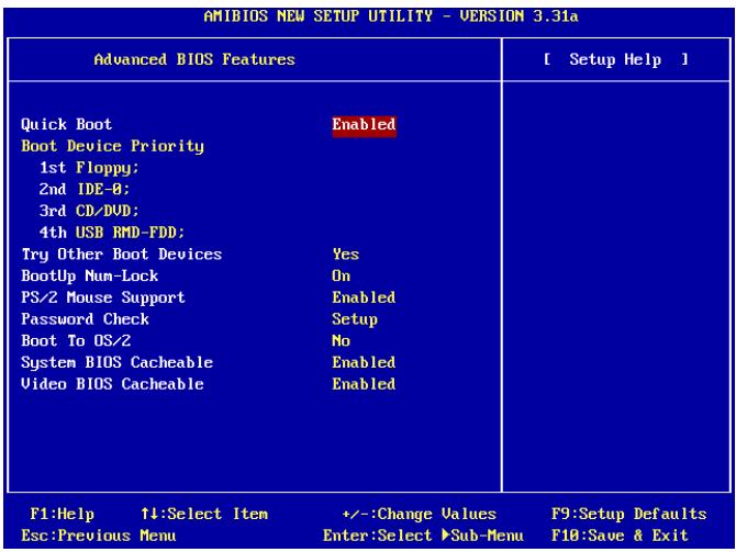
Quick Boot:
This item speeds up the POST (Power On Self Test) after powering on the system. Leave this option to its default [Enabled] setting to allow the BIOS shorten or skip some check items during POST.
How to use the Quick Boot function?
When you start to get in the boot sequence, press <F6> key one time, then you can see the "Select First Boot Device" menu show up. Choose the first boot device you want then press <Enter> key to continue the boot sequence.
Boot Device Priority:
This item selects the booting priority. The BIOS will boot the operating system according to the sequence of the drive selected.
Try Other Boot Other Devices:
When set to [Enabled], this item boots your system from devices other than those selected in the [Boot Device Priority] option.
BootUp Num-Lock:
This item determines the default state of the numeric keypad at system booting up.
- [On]: The numeric keypad functions as number keys.
- [Off]: The numeric keypad functions as arrow keys.
PS/2 Mouse Support:
This item selects to support the PS/2 mouse or not.
- [Enabled]: Allow the system to use a PS/2 mouse.
- [Disabled]: This option will prevent the PS/2 mouse port from using system resources and will prevent the port from being active. Use this setting if installing a serial mouse.
Password Check:
This item determines when the system will prompt for password - every time the system boots or only when enters the BIOS setup.
- [Setup]: The password is required only when accessing the BIOS Setup.
- [Always]: The password is required each time the computer boots up.
NOTE: Don't forget your password. If you forget the password, you will have to open the computer case and clear all information in the CMOS before you can start up the system. But by doing this, you will have to reset all previously set options.
Boot To OS/2:
This item modifies the OS/2 boot up settings.
- [No]: This option allows the system to boot up into non-OS/2 environments. This is the default setting and should not be changed unless OS/2 is the main operating system and more than 64 MB of system memory is installed.
- [Yes]: This option allows the system to boot up to an OS/2 environment when more than 64 MB of system memory is installed.
System BIOS Cacheable:
Enabling the System BIOS cache will allow accesses to the system BIOS ROM addressed at F0000H-FFFFFFH, if the cache controller is enabled. The larger the range of the Cache RAM, the higher the efficiency of the system will be.
Video BIOS Cacheable:
Enabling the Video BIOS cache will allow access to the video BIOS addressed at C0000H to C7FFFH to be cached, if the cache controller is enabled. The larger the range of the Cache RAM, the faster the video performance will be.
3-4. Advanced Chipset Features
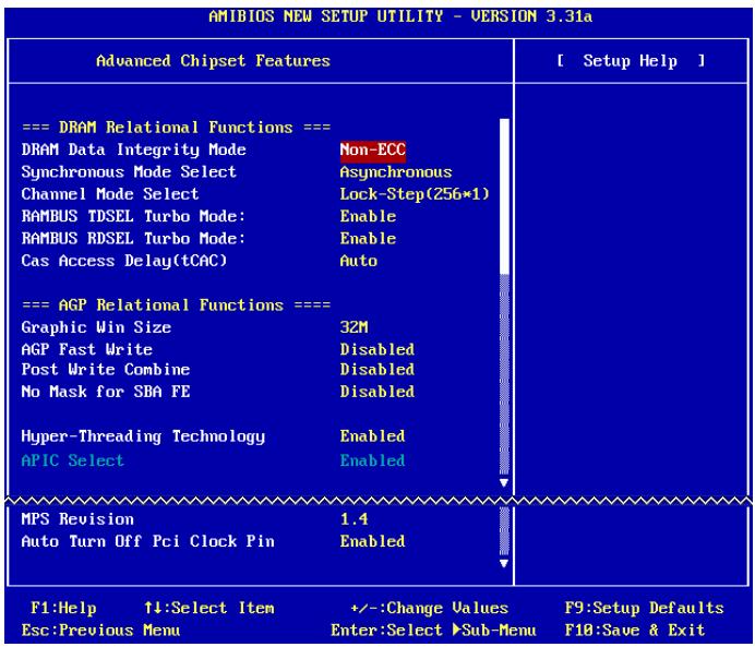
DRAM Data Integrity Mode:
This item selects the type of DRAM in your system. ECC is "Error Checking and Correction". Choose the ECC option only when your memory is ECC type.
Synchronous Mode Select:
This item selects the Synchronous mode of the signal between CPU and RAM for system performance. Choose [Asynchronous] mode only when compatibility issue occurs.
Channel Mode Select:
This item selects the RDRAM channel mode.
| RAMBUS TDSEL Turbo Mode:Leave this item to its default setting. |
| RAMBUS RDSEL Turbo Mode:Leave this item to its default setting. |
| Cas Access Delay(tCAC):Leave this item to its default setting. |
| Graphic Win Size:This item specifies the amount of system memory that can be used by AGP card. |
| AGP Fast Write:If your AGP card supports this “Fast Write” function, this option will increase your system performance by selecting [Enabled], but it may also decrease system compatibility. |
| AGP Capability:This item selects the proper AGP data transfer rate for your AGP card. |
| Post Write Combine:While as the AGP command is usually executed one by one, this item selects executing the AGP command together. Choose [Enabled] only when compatibility issue occurs. |
| No Mask for SBA FE:This item selects masking the AGP calibrating signal for certain VGA cards. Choose [Enabled] only when compatibility issue occurs. |
| Hyper-Threading TechnologyLeave this item to its default setting to enable the simultaneous multi-threaded (SMT) processor so as to make one physical processor looks like two logical processors to the OS and applications.This option is for CPU with Hyper-Threading Technology only. For more information on“Hyper-Threading Technology”, please visit Intel Web site athttp://www.intel.com/homepage/land/hyperthreading.htm , http://www.intel.com/design/chipsets/ht/. |
| APIC Select:· [Enabled]: The APIC (Advanced Programmable Interrupt Controller) mode will expand available IRQs resources for the system.· [Disabled]: The system will use the default PCI IRQs for all devices, and will not increase the number of PCI IRQs. |
| NOTE: Assume you enable this item first before installing Windows® 2000 or Windows® XP operating system, disabling this item and then reboot the system will cause the system hang. You have to change this option to [Enabled] to make your system back to normal. |
* MPS Revision:
This option specifies which version of MPS (Multi-Processor Specification) this motherboard will use. Select [1.1] when using an older operating system for dual processor executing.
Auto Turn Off Pci Clock Pin:
This item turns off the PCI clock that is not in use. Leave this option to its default settings.
3-5. Power Management Features
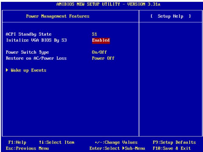
ACPI Standby State:
This item selects the type of Suspend mode.
[S1(POS)]: Enables the Power On Suspend function.
[S3(STR)]: Enables the Suspend to RAM function.
[Auto]: Automatically select the type of suspend mode.
Initialize VGA BIOS By S3:
When set to [Enabled], this item allows the system to initialize VGA BIOS after woke up from S3 state. Leave this item to its default settings to let the display screen back to normal after woke up from S3 state.
Power Switch Type:
This item selects the function type of power switch.
- [On/Off]: Power on and power off the system.
[Suspend]: Suspendng the system.
Restore on AC/Power loss:
This item sets the system power state when it recovers from AC power loss.
- [Power Off]: The system turns off when power returns.
- [Power On]: The system turns on when power returns.
- [Last State]: The system returns to the previous power state.
Wake Up Events:
Click
| AMBIOS NEW SETUP UTILITY - VERSION 3.31a | ||
| Wake up Events | [ Setup Help ] | |
| Keyboard PowerOn Function | Disabled | If set to Specific Key, Ctrl+Alt+BackSpace is only one Power ON event. If set to password, please press [Enter] to input password and its maximum password is 5 character. |
| Resume by USB | Disabled | |
| Wake Up by PS2 Mouse | Disabled | |
| - PS2 MOUSE WakeUp Node Select | Normal | |
| Wake Up by PME | Disabled | |
| Wake Up by Modem Ring | Disabled | |
| Wake Up by RTC | Disabled | |
| - RTC Alarm Date | Every Day | |
| - RTC Alarm Hour | 12 | |
| - RTC Alarm Minute | 38 | |
| - RTC Alarm Second | 08 | |
| F1:Help 11:Select Item | +/:-Change Values | F9:Setup Defaults |
| Esc:Previous Menu | Enter:Select >Sub-Menu | F10:Save & Exit |
Keyboard PowerOn Function:
This item selects the wake-up method by keyboard.
- [Disabled]: Disable the keyboard power-on function.
- [Any Key]: Allows the keyboard power-on function by any keypad.
- [Specific Key]: Allows the keyboard power-on function only by <Ctrl> + <Alt> + <Back~Space> key.
- [Password]: Allows the keyboard power-on function by a password of 5-character length.
Resume by USB:
When set to [Enabled], any event occurring at USB port will awaken the system that has been powered down.
Wake Up by PS2 Mouse:
When set to [Enabled], any event occurring at PS/2 mouse port will awaken the system that has been powered down.
PS2 MOUSE Wakeup Mode Select:
This item selects the mode to awaken the system by PS/2 mouse.
- [Normal]: Any movement of the mouse will affect.
- [Only Button]: Only by pushing the mouse buttons will affect.
Wake Up by PME:
When set to [Enabled], any event occurring at LAN port will awaken the system that has been powered down.
Wake Up by Modem Ring:
When set to [Enabled], any event occurring by modem ring will awaken the system that has been powered down.
Wake Up by RTC:
When set to [Enabled], you can set the date, hour, minute and second you want for RTC (Real-Time Clock) to awaken the system from suspend mode.
\*RTC Alarm Date:
Select the date for RTC alarm.
\*RTC Alarm Hour:
Select the hour for RTC alarm.
\*RTC Alarm Minute:
Select the minute for RTC alarm.
\*RTC Alarm Second:
Select the second for RTC alarm.
3-6. PnP/PCI Configurations
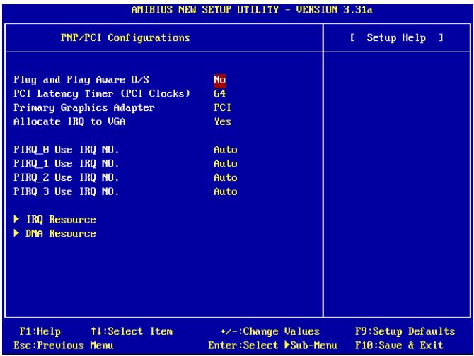
Plug and Play Aware O/S:
This item allows you to use a PnP operating system to configure the PCI bus slots instead of the BIOS. When set to [Yes], the interrupts may be reassigned by the BIOS. If you installed a non-PnP OS, or if you want to prevent re assigning of interrupt settings, keep the default setting [No].
PCI Latency Timer (PCI Clocks):
This item controls how long each PCI device can hold the bus before another takes over. When set to higher values, every PCI device can conduct transactions for a longer time and thus improve the effective PCI bandwidth. For better PCI performance, you should set the item to higher values.
Primary Graphics Adapter:
This item selects whether to initialize the AGP or PCI first when the system boots.
[AGP]: When the system boots, it will first initialize the AGP.
- [PCI]: When the system boots, it will first initialize PCI.
Allocate IRQ to VGA:
This item assigns an IRQ for the VGA card installed.
- [Yes]: Automatically assign an IRQ for the VGA card installed.
- [No]: The IRQ that was previously occupied by the VGA card will be available for new device.
PIRQ 0 Use IRQ No.~PIRQ 3 Use IRQ No.:
This item specifies the IRQ number manually or automatically for the devices installed on PCI slots.
For the relations between the hardware layout of PIRQ, INT# (PCI slot IRQ signals) and devices, please refer to the table below:
| Signals | PIRQ_0Assignment | PIRQ_1Assignment | PIRQ_2Assignment | PIRQ_3Assignment |
| AGP | INT A | INT B | ||
| PCI-1 | INT A | INT B | INT C | INT D |
| PCI-2 | INT B | INT D | INT C | INT A |
| PCI-3 | INT B | INT A | INT D | INT C |
| PCI-4 | INT D | INT A | INT B | INT C |
| PCI-5 | INT C | INT D | INT A | INT B |
| LAN | INT A | |||
| SATA | INT A |
NOTE:
PCI slot 1 shares IRQ signals with AGP slot.
PCI slot 2 shares IRQ signals with PCI slot 3.
PCI slot 4 shares IRQ signals with LAN.
PCI slot 5 shares IRQ signals with SATA.
- If you want to install two PCI cards into those PCI slots that share IRQ with one another at the same time, you must make sure that your OS and PCI devices' driver supports the IRQ sharing function.
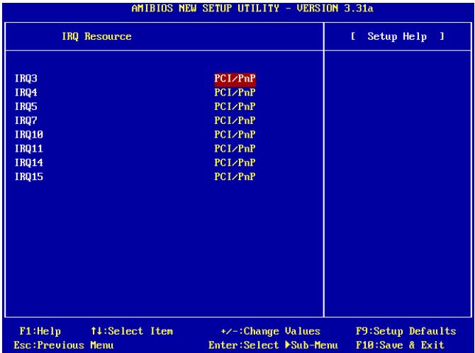
\* IRQ Resources:
This item modifies the IRQ settings.
- [PCI/PnP]: This setting allows the specified IRQ to be used by a PCI/PnP device.
- [Reserve]: This setting allows the specified IRQ to be used by a legacy ISA device.
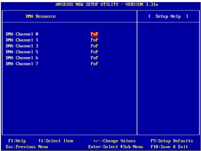
\* DMA Resources:
This item modifies the DMA settings.
- [PnP]: This setting allows the specified DMA to be used by a PCI/PnP device.
- [Reserve]: This setting allows the specified DMA to be used by a legacy ISA device.
3-7. Integrated Peripherals
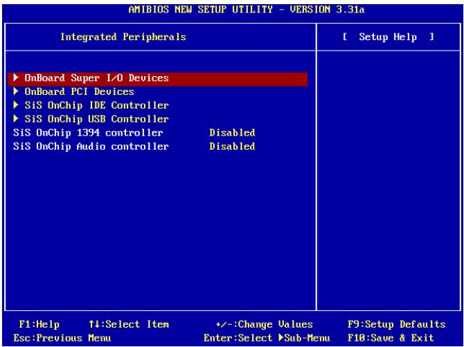
OnBoard Super I/O Devices:
Click
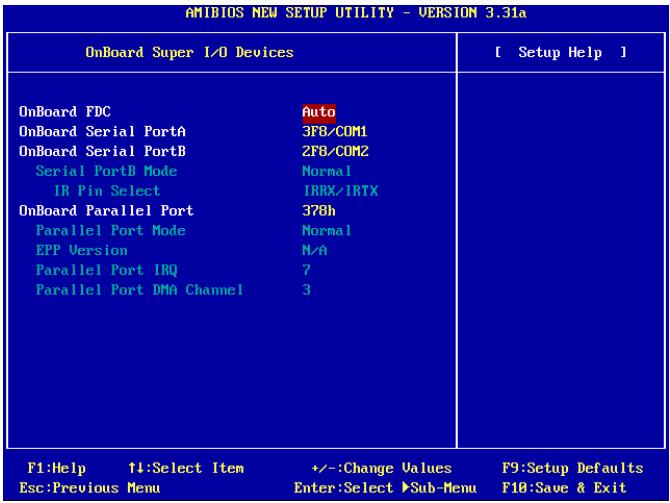
OnBoard FDC:
- [Enabled]: Enables the onboard floppy disk controller.
- [Disabled]: Enables the onboard floppy disk controller.
Onboard Serial PortA / Onboard Serial PortB:
This item determines which I/O addresses the onboard Serial Port A & B controller will access.
- [Auto]: The system automatically select an I/O address for the onboard Serial Port A & B.
- [3F8/COM1, 2F8/COM2, 3E8/COM3, 2E8/COM4]: Allows you to manually select an I/O address for the onboard Serial Port A & B.
- [Disabled]: Enables the onboard Serial Port A and/or B.
* Serial PortB Mode:
This item sets the operation mode for Serial Port B.
* IR Pin Select:
This item selects the pin headers for IR device.
- [IRRX/IRTX]: Select this option when using an internal IR module connected to the onboard IR header.
[SINB/SOUTB]: Select this option when connecting an IR adapter to COM B.
Onboard Parallel Port:
This item specifies the I/O address used by the parallel port.
- [Disabled]: This option prevents the parallel port from accessing any system resources. When the value of this option is set to Disabled, the printer port becomes unavailable.
[378]: This option allows the parallel port to use 378 as its I/O port address. The majority of parallel ports on computer systems use IRQ7 and I/O Port 378H as the standard setting.
[278]: This option allows the parallel port to use 278 as its I/O port address.
[3BC]: This option allows the parallel port to use 3BC as its I/O port address.
* Parallel Port Mode:
This item specifies the parallel port mode.
- [Normal]: Allows the standard parallel port mode to be used.
- [SPP]: (Standard Parallel Port) Allows bi-directional parallel port operation at normal speed.
- [EPP]: (Enhanced Parallel Port) Allows bi-directional parallel port operation at maximum speed.
- [ECP]: (Extended Capabilities Port) Allows bi-directional parallel port operation at a speed faster than the normal mode's data transfer rate.
* EPP Version:
This item selects the EPP version for the parallel port when the mode selected for the parallel port mode is EPP.
* Parallel Port IRQ:
This item specifies the IRQ used by the parallel port.
[5]: This option allows the serial port to use Interrupt 5.
[7]: This option allows the serial port to use Interrupt 7. The majority of parallel ports on computer systems use IRQ7 and I/O Port 378H as the standard setting.
* Parallel Port DMA Channel:
This item selects a DMA channel for the parallel port.
OnBoard PCI Devices:
Click
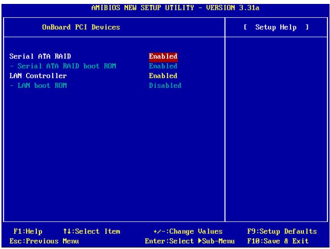
Serial ATA RAID
This item selects the onboard Serial ATA controller. When set to [Enabled], two additional channels will be provided for adding high performance devices to system.
* Serial ATA RAID boot ROM
This item enables or disables the Boot ROM on Serial ATA controller.
LAN Controller
This option enables or disables the LAN controller.
* LAN boot ROM
This item enables or disables the Boot ROM on LAN controller.
SiS OnChip IDE Controller:
Click
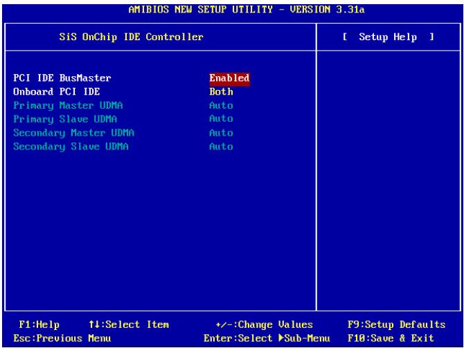
PCI IDE BusMaster:
This item decides whether the IDE controller on the PCI local bus has the bus mastering capability.
Onboard PCI IDE:
This item allows you disable all onboard PCI IDE devices, or enable one of them.
- Primary Master/Slave UDMA, Secondary Master/Slave UDMA:
These fields set the Ultra DMA in use.
- [Auto]: The BIOS will automatically select the best available option after checking your hard drive or CD-ROM.
- [Disabled]: The BIOS will not detect these categories.
SiS OnChip USB Controller:
Click
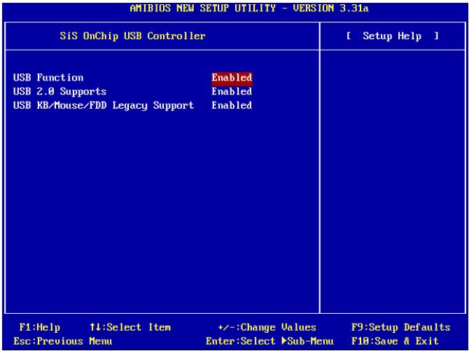
USB Function:
This option enables or disables the USB function.
USB 2.0 Supports:
This option enables or disables the USB 2.0 function. When set to [Disabled], the USB port will be running at USB 1.1 Specification.
USB KB/Mouse/FDD Legacy Support:
This option enables or disables the USB support in DOS environment.
SiS OnChip 1394 Controller:
This option enables or disables the onchip IEEE1394 controller.
SiS OnChip Audio Controller:
This option enables or disables the onchip audio controller.
3-8. PC Health Status
You can set the warning temperature for your computer system, and you can check the fan speeds and power supply voltages of your computer system. The features are useful for monitoring all the important parameters within your computer system. We call it the PC Health Status.
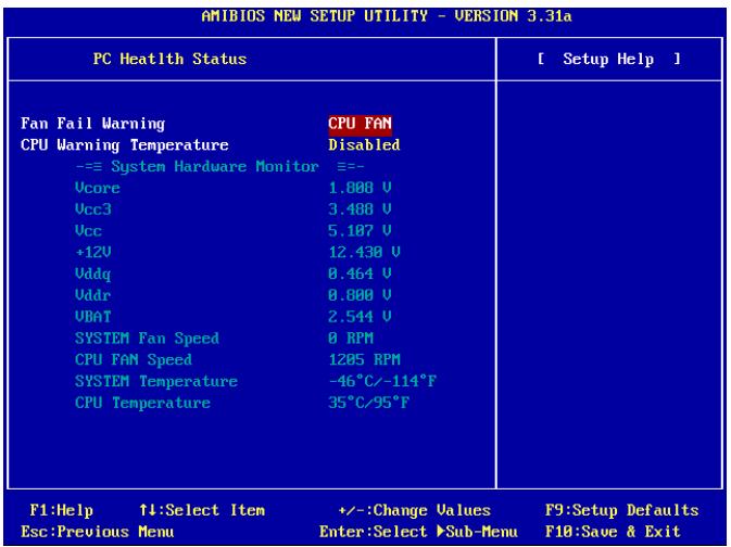
FAN Fail Warning:
This item selects which fan will be monitored for fan fail warning.
CPU Warning Temperature:
This item selects the temperature you want the system to send out a warning message to PC speaker.
All Voltages, Fans Speed and Thermal Monitoring:
These unchangeable items list the current status of the CPU and environment temperatures, fan speeds, and system power voltage.
NOTE: The hardware monitoring features for temperatures, fans and voltages will occupy the I/O address from 294H to 297H. If you have a network adapter, sound card or other add-on cards that might use those I/O addresses, please adjust your add-on card I/O address to avoid using these addresses.
3-9. Set Password
This option protects the BIOS configuration or restricts access to the computer itself.
3-10. Load Optimized Defaults
This option loads the BIOS default values that are factory settings for optimal-performance system operations.
3-11. Load Fail-Safe Defaults
This option loads the BIOS default values for the most stable, minimal-performance system operations.
3-12. Save & Exit Setup
This option saves your selections and exits the BIOS setup menu.
3-13. Exit Without Saving
This option exits the BIOS setup menu without saving any change.
Appendix A. Install SiS Chipset Driver
NOTE: Please install this SiS Chipset driver first after having installed the Windows operating system.
The installation procedures and screen shots in this section are based on Windows XP operating system. For those of other OS, please follow its on-screen instruction.
Insert the Driver & Utility CD into CD-ROM drive, it should execute the installation program automatically. If not, double-click the execution file at the main directory of this CD to enter the installation menu.
After entering the installation menu, move your cursor to [Driver] tab. Click [SiS Chipset Driver]. The following screen appears.
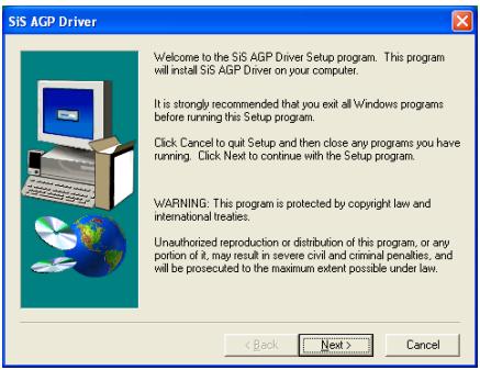
1. Click [Next].
![ABIT SI7 - Click [Next]. - 1](/content/2025/01/174582/images/55d65d4ac4c4a53dd48119364a754b5e1ee6726f7c2111a5bef39a563b69813c.jpg)
2. Click [Next].
![ABIT SI7 - Click [Next]. - 1](/content/2025/01/174582/images/46845c763688b6b77a6f5b9496d3d1b6c1de5af55ce3e3d5c8cd62d1d30c0cbd.jpg)
- Choose [Yes, I want to restart my computer now.], and click [Finish] to complete setup.
![ABIT SI7 - Click [Next]. - 2](/content/2025/01/174582/images/5fbd5f3352d303ff0c9f0fb1a3a3215d2217b94b1203ec4c8a54711c3fdb2e42.jpg)
Appendix B. Install SiS IDE Driver
The installation procedures and screen shots in this section are based on Windows XP operating system. For those of other OS, please follow its on-screen instruction.
Insert the Driver & Utility CD into CD-ROM drive, it should execute the installation program automatically. If not, double-click the execution file at the main directory of this CD to enter the installation menu.
After entering the installation menu, move your curser to [Driver] tab. Click [SiS IDE Driver]. The following screen appears.
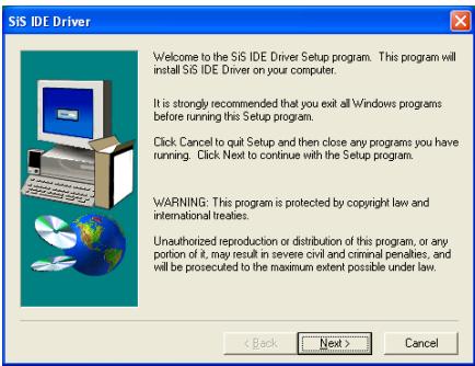
1. Click [Next].
![ABIT SI7 - Click [Next]. - 1](/content/2025/01/174582/images/4095f22da301017cf0641ddc2dd136520539dbc3bf60a8f7c3202cb1a67c0e4e.jpg)
2. Click [Next].
![ABIT SI7 - Click [Next]. - 1](/content/2025/01/174582/images/29a417a3cf5d2fbba2c0e0e2e680e973da140d4921370687fe984349c7a6973b.jpg)
- Choose [Yes, I want to restart my computer now.], and click [Finish] to complete setup.
![ABIT SI7 - Click [Next]. - 2](/content/2025/01/174582/images/ef5d1ddd0bfc347c22f19988d8f8dfb02221c323b950142b7505ad5a7f5fac0f.jpg)
Appendix C. Install Audio Driver
The installation procedures and screen shots in this section are based on Windows XP operating system. For those of other OS, please follow its on-screen instruction.
Insert the Driver & Utility CD into CD-ROM drive, it should execute the installation program automatically. If not, double-click the execution file at the main directory of this CD to enter the installation menu.
After entering the installation menu, move your cursor to [Driver] tab. Click [RealTek Audio Driver]. The following screen appears.
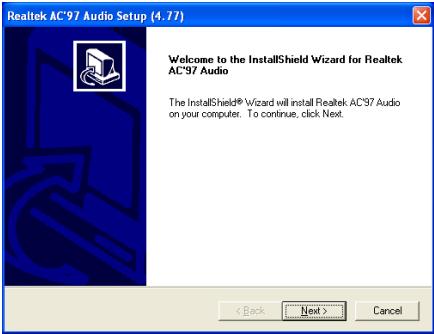
1. Click [Next].
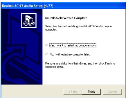
2. Choose [Yes, I want to restart my computer now.], and click [Finish] to complete setup.
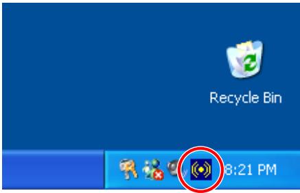
3. After the system restarted, a shortcut icon appears at the right corner of Windows task bar.
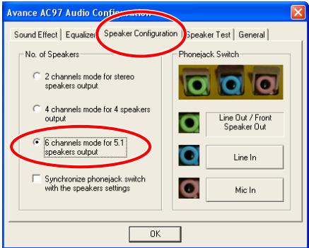
4. In this Speaker Configuration tab, select [6 channels mode for 5.1 speakers output] to enable 6-channel audio system.
Note: To keep a normal operation of 5.1 speakers output, please do not change the settings of "Line In" and "Mic In" in this menu.
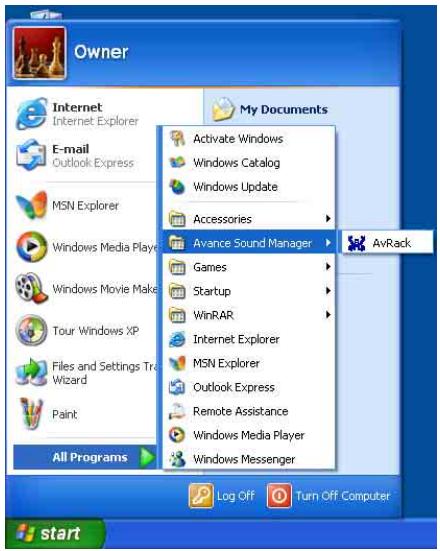
- To run the [AvRack] control panel, click [Start] [All Programs] [Avance Sound Manager] [AvRack].
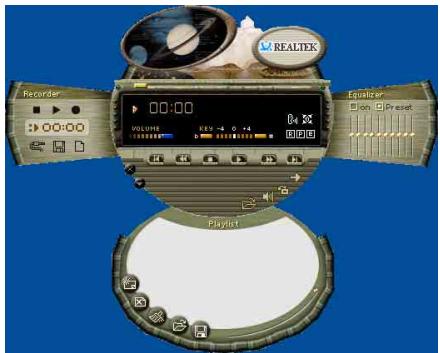
- The AvRack control panel with Recorder, Equalizer, and Playlist window appears.
Appendix D. Install LAN Driver
The installation procedures and screen shots in this section are based on Windows XP operating system. For those of other OS, please follow its on-screen instruction.
Insert the Driver & Utility CD into CD-ROM drive, it should execute the installation program automatically. If not, double-click the execution file at the main directory of this CD to enter the installation menu.
For SI7:
After entering the installation menu, move your cursor to [Driver] tab. Click [Broadcom 10/100 LAN Driver]. The following screen appears.
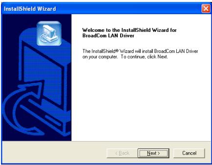
- Click [Next].
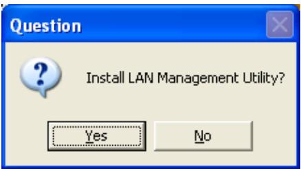
- Click [Yes].
- Click [Next].
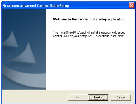
- Click [Yes].
- Click [Next].
6. Click [OK].
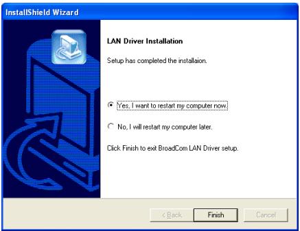
7. Choose [Yes, I want to restart my computer now.], and click [Finish] to complete setup.
Note: In order to enable the WOL (Wake-up On LAN) function for SI7 and SI7-G model in Windows 2000 and Windows XP, it is necessary to change the value of the "Wake Up Capabilities" property into "Magic Frame". Please refer to the following two steps:
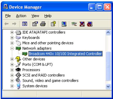
- After finished the driver installation, check the [Network adapters] in the [Device Manager]. You will find the [Broadcom 440x 10/100 Integrated Controller] is successfully installed.
Select [Broadcom 440x 10/100 Integrated Controller]. Right click your mouse to enter its properties.
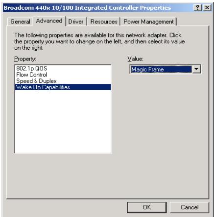
- Select [Advanced] tab. Move your cursor to select the [Wake Up Capabilities] property option and then set the value option to [Magic Frame]. Click [OK] and restart your computer to complete setup.
For SI7-G:
After entering the installation menu, move your curser to [Driver] tab. Click [Broadcom Gigabit LAN Driver]. The following screen appears.
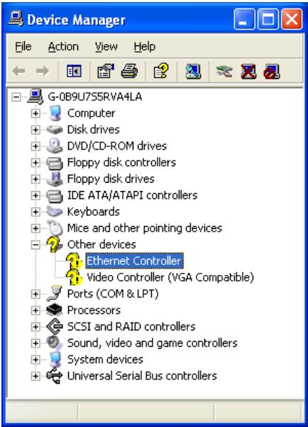
1. Check [Device Manager]. Click [Ethernet Controller].
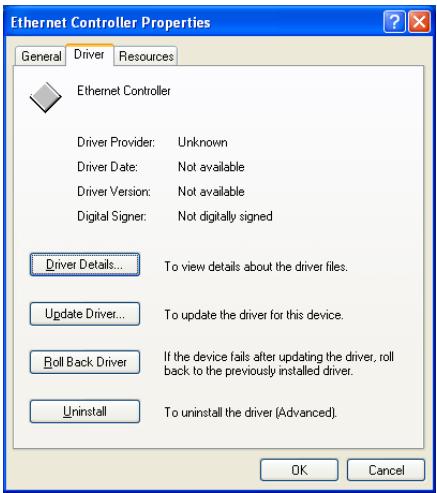
2. Select [Driver] tab in the [Ethernet Controller Properties]. Click [Update Driver].
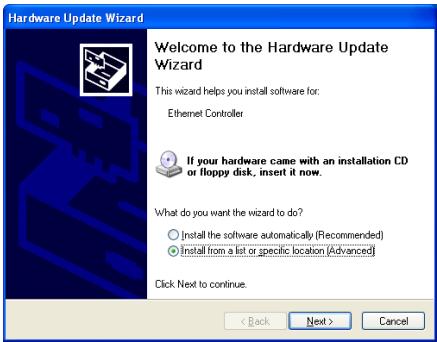
3. Check [Install from a list or specific location], and then click [Next].
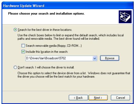
- Check [Include this location in the search]. Click [Browse] button to locate the driver or type in the path [D:\Drivers\lan\Broadcom\5702]. D: is the CD-ROM drive. Click [Next] to continue.
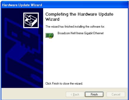
- Click [Finish].
- Back to the [Ethernet Controller Properties]. Click [Close] to finish driver update.
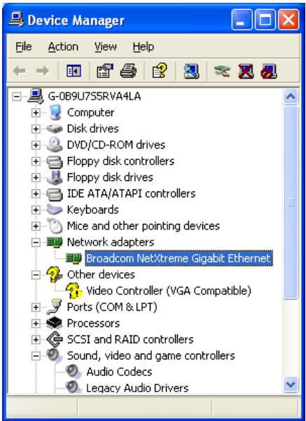
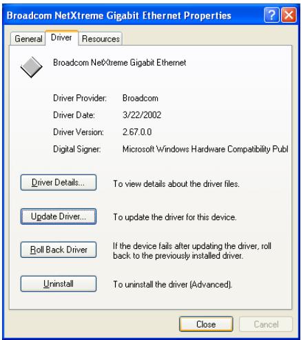
- Check [Device Manager] again. [Broadcom NetXtreme Gigabit Ethernet] is successfully upgraded.
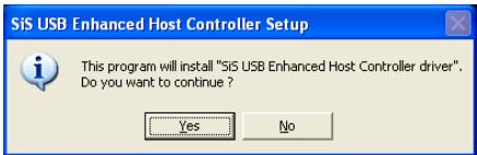
Appendix E. Install SiS USB 2.0 Driver
For Windows XP:
- Make sure your system is connected to Internet.
- Link to Microsoft Windows XP SP1 download page at http://www.microsoft.com/WindowsXP/pro/downloads/servicepacks/sp1/default.asp.
- Click [Network Installation] in "Installing SP1 on Multiple Computers" column. (You can choose [Express Installation] in "Installing SP1 on Your Computer" column, if you don't want to download full SP1 file.)
- Select your language and click [Go] button.
- Click [SP1 Network Installation (32-Bit)] to start downloading Windows XP SP1.
- After download finished, execute the SP1 file to update your Windows.
- After Windows update finish, click [Start] [Control Panel].
- Double click [System].
- Select [Hardware] tab and click [Device Manager].
- Right click on [Universal Serial Bus (USB) Controller] and click [Update Driver...].
- Click [Next]. The system will search and install USB 2.0 driver automatically.
For Window 2000:
The installation procedures and screen shots in this section are based on Windows 2000 operating system. For those of other OS, please follow its on-screen instruction.
Insert the Driver & Utility CD into CD-ROM drive, it should execute the installation program automatically. If not, double-click the execution file at the main directory of this CD to enter the installation menu.
After entering the installation menu, move your cursor to [Driver] tab. Click [USB 2.0 Driver]. The following screen appears.
- Click [Yes].
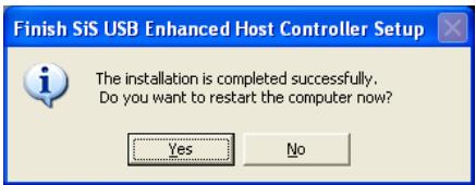
- Click [Yes].

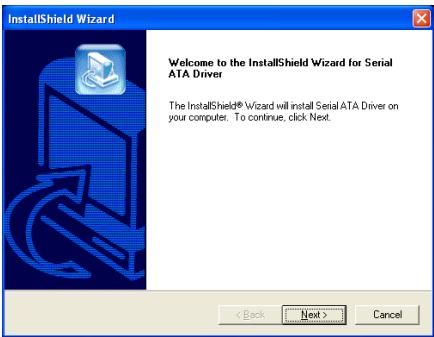
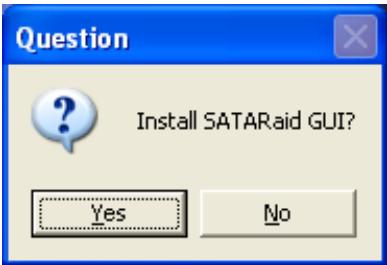
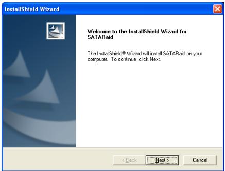
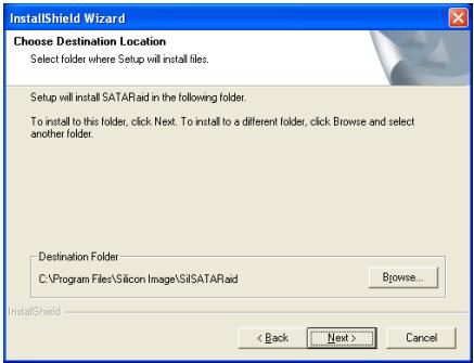
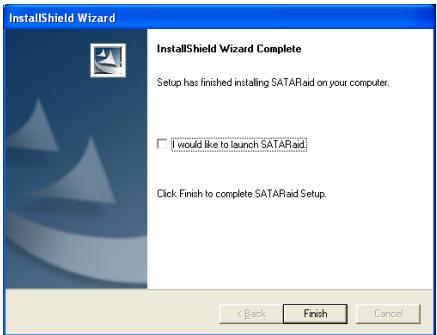
Appendix F. Install Serial ATA RAID Driver
The installation procedures and screen shots in this section are based on Windows XP operating system. For those of other OS, please follow its on-screen instruction.
Insert the Driver & Utility CD into CD-ROM drive, it should execute the installation program automatically. If not, double-click the execution file at the main directory of this CD to enter the installation menu.
After entering the installation menu, move your cursor to [Driver] tab. Click [Serial ATA RAID Driver]. The following screen appears.
- Click [Next].
- Click [Yes].
- Click [Next].
- Click [Next].
- Click [Next].
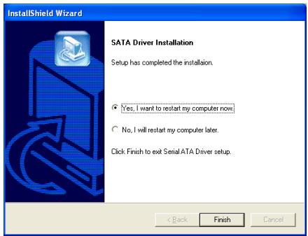
- Choose [Yes, I want to restart my computer now.], and click [Finish] to complete setup.
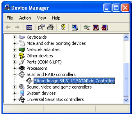
- Check [Device Manager]. [Silicon Image SiI 3112 SATARaid Controller] is successfully installed.
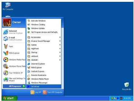
- To run the [SATARaid] application, click [Start] [All Programs] [SATARaid].
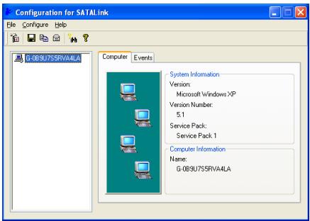
- This is the SATALink configuration menu. For more information on how to operate, please refer to the "Help" menu.
BIOS Setup for Serial ATA RAID
The SI7/SI7-G supports Striped (RAID 0) and Mirrored (RAID 1) RAID set. For the striped RAID set, the identical drives can read and write data in parallel to increase performance. The Mirrored RAID set creates a complete backup of your files. Striped and Mirrored RAID set requires 2 hard disks to do so.
RAID Configuration Utility Menu
Main Menu
Reboot your system. Press <CTRL> + <S> or <F4> key while booting up the system to enter the BIOS setting menu. The main menu of BIOS Setting Utility appears as shown below:
| RAID Configuration Utility - Silicon Image Inc. Copyright (C) 2002 | ||
| Create RAID set Delete RAID set Rebuild Mirrored set Resolve Conflicts | ||
| + 0 PM Master 33073H3 29312MB 1 SM Master 33073H3 29312MB | ||
| T1 Select Menu ESC Previous Menu Enter Select Ctrl+B Exit * First HDD | ||
To select the option in this menu, you may:
- Press < > (up, down arrow) to choose the option you want to confirm or to modify.
- Press
to confirm the selection. - Press
to return to previous menu. - Press <Ctrl-E> to exit the RAID configuration utility.
NOTE: If you want to create a RAID 0 (striping) array, all the data stored in the hard disks will first be erased! Please backup the hard disk data before starting to create the RAID array.
If you want to create a RAID 1 (mirroring) array, please make sure which hard disk is the source disk and which one is the destination disk. If you make a mistake, you may copy the blank data to the source disk, which will result in both hard disks becoming blank!
Option 1 Create RAID set
This item allows you to create a RAID array.
After you had selected the function from the main menu, press the
| RAID Configuration Utility - Silicon Image Inc. Copyright (C) 2002 | ||
| Create RAID set Delete RAID set Rebuild Mirrored set Resolve Conflicts | Striped Mirored | |
| * 0 PM Master 33073H3 29312MB 1 SM Master 33073H3 29312MB | T1 Select Menu ESC Previous Menu Enter Select Ctrl-E Exit * First HDD | |
- Array Mode:
This item allows you to select the appropriate RAID mode for the desired array. There are two modes to choose. When you choose a "Striped" or "Mirrored" RAID set, the utility will ask "Are You Sure?" before the Creating RAID process. Press <Y> to confirm.
NOTE: It is highly recommended to attach hard disks with the same model in reaching the RAID performance.
Striping (RAID 0): This item is recommended for high performance usage. Requires at least 2 disks.
Mirror (RAID 1): This item is recommended for data security usage. Requires at least 2 disks.
Option 2 Delete RAID set
This item allows you to remove a RAID Array on this onboard Serial ATA RAID controller.
NOTE: After you have made and confirmed this selection, all the data stored in the hard disk will be lost. (The entire partition configuration will be deleted too.)
Option 3 Rebuild Mirrored set
This item allows you to rebuild only "Mirrored" RAID set.
You need to check which hard disk is the source disk and which one is the destination disk when you decide to rebuild mirrored RAID set.
Option 4 Resolve Conflicts
When a RAID set is created, the metadata written to the disk includes drive connection information (Primary Channel, Secondary Channel).
If, after a disk failure, the replacement disk was previously part of a RAID set (or used in another system), it may have conflicting metadata, specifically in reference to the drive connection information. If so, this will prohibit the RAID set from being either created or rebuilt.
In order for the RAID set to function properly, this old metadata must be first overwritten with the new metadata. To resolve this, select "Resolve Conflict". The correct metadata, including the correct drive connection information; will then be written to the replacement disk.
NOTE: For more information on RAID function, please refer to the RAID Management Software enclosed in the CD that came packed with this motherboard.
Appendix G. BIOS Update Guide
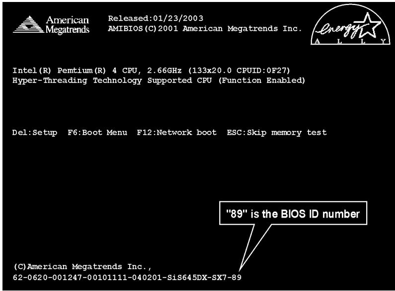
The procedure illustrated here is based on the model SX7-533 as an example; all other models follow the same process.
- First, find out the model name and version number of this motherboard. You can find a bar-code sticker typed with model name and version number on motherboard PCB.
- Find out the current BIOS ID. For example, in this case, the current BIOS ID is [89]. If you already have the latest BIOS, no any update action is necessary. If your BIOS is not the latest BIOS, go on to the next step.
- Download the correct BIOS file from our Web site.
- Double click the downloaded file, it will self-extract to [amiflash.exe] and [^*.rom] files.
- Make a bootable floppy disk and copy the necessary files onto it. You may make a floppy disk bootable either in Explorer or in the DOS prompt mode.
[c:\]format a:/s
After formatting and transferring the system to the floppy disk, copy two files into it. One is the BIOS flash utility [amiflash.exe] and the other is the decompressed BIOS binary [·^*.rom] file.
![ABIT SI7 - [c:\]format a:/s - 1](/content/2025/01/174582/images/8ee7a1c762b52e9e68b1dd83039465a6e7e3ec6ac10209e0111ab08f28aadc59.jpg)
- Please set the first boot sequence as "Floppy" in BIOS and boot off the floppy disk.
![ABIT SI7 - [c:\]format a:/s - 2](/content/2025/01/174582/images/383aa8f3d9bbc62a0d49ef2decbd9712e2b20216100a1c0c33a3ced51054ff9d.jpg)
- Flash the BIOS in pure DOS mode.
A:\>amiflash sx7_89.rom
- When the flash process is complete, you can see the completed message that will ask you to restart your system
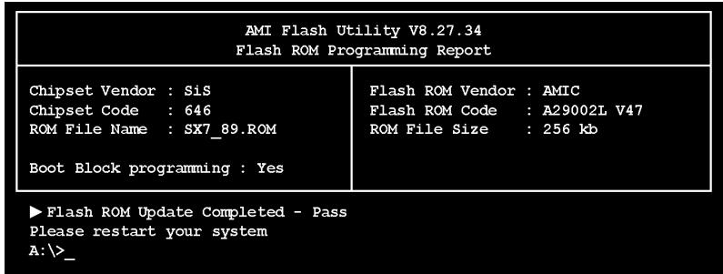
Note
- The AMI flash utility cannot be completed under the Windows environment. It must be done in a pure DOS environment.
- You should check which BIOS file is to be used with your motherboard, don' flash with the wrong BIOS file. Otherwise, it may cause system malfunctions.
Appendix H. Hardware Monitoring (The Winbond Hardware Doctor Utility)
The Winbond Hardware Doctor is a self-diagnostic system for PCs. It protects PC hardware by monitoring several critical items including power supply voltages, CPU & system fan speeds and CPU and system temperatures. These items are important for the system operation. Errors may result in permanent damage to the PC. Once any item is out of its normal range, a warning message pops up reminding you to take proper measures.
The installation procedures and screen shots in this section are based on Windows XP operating system. For those of other OS, please follow its on-screen instruction.
Insert the Driver & Utility CD into CD-ROM drive, it should execute the installation program automatically. If not, double-click the execution file at the main directory of this CD to enter the installation menu.
After entering the installation menu, move your curser to [Hardware Doctor] tab. Click [Hardware Doctor]. The following screen appears.
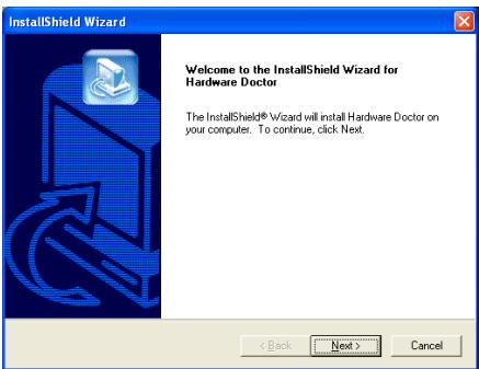
1. Click [Next].
2. Click [Next].
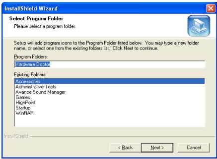
3. Click [Next].
4. Click [Next].
- Choose [Yes, I want to restart my computer now.] and click [Finish] to complete setup.
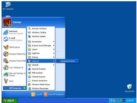
- Execute the Hardware Doctor by entering the Windows Menu [Start] [Programs] [Winbond] [Hardware Doctor].
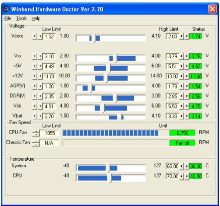
- This screen appears. Hardware Doctor shows you the status of Voltage, Fan Speed, and Temperature readings as well. If any reading is critical or over its limitation, the reading turns
red. Also, a pop-up window appears warning you the system has a problem!
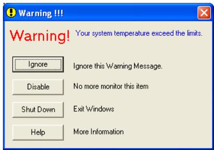
- This is the warning message window:
Ignore: You can ignore the warning message of the item, but it will pop up again when an error of the same item reoccurs.
Disable: The chosen item will be no longer monitored thereafter, unless you activate it in the "Configuration" page.
Shutdown: Choosing this button will shutdown the computer.
Help: You can read more information and self-diagnose simple problems.
If the warning message pops up due to the wrong warning limit, you can adjust it in the "Configuration" option. For example, if you set the temperature high limit to 40^ , you will easily exceed the "proper" temperature.
Pay attention to two things when you want to make any change to the "Configuration" option. Firstly, you have to make sure your new setting is in the proper range. Secondly, after you finished the configuration, you have to save it. Otherwise, the program will start with the default value next time.
If you encounter any problem or have any question about the software settings and adjustments, please use the Winbond hardware doctor on-line help. It should give you enough information to answer your questions.
Appendix I. Installation Guide for Suspend to RAM
Suspend To RAM (STR) is a cost-effective, optimal implementation of the ACPI 1.0 specification. The ACPI specification defines the S3 sleep state, in which all system context is lost except system memory. CPU, cache, and chip set context are lost in this state. Hardware maintains memory context and restores some CPU and L2 configuration context.
The STR function enables a PC to achieve the S3 state during idle periods, then quick "wake up" and retrieve the last "state" of the system before it went to sleep. When idle, STR-enabled systems consume only a small fraction of the power used for full operation. Instead of shutting down the system to save power when not in use and then having to reboot later, users can let the STR function take over and not have to worry about using power to run all the electronics, fans and disks. When needed, a PC with STR function can restore all applications and features to an operational state within a few seconds.
The following description will tell you how to install the STR function and to use it.
After the operating system had been installed successfully, reboot your computer, you can see these ACPI items show up in the "Device Manager" menu by entering Start Settings Control Panel System System Properties Hardware:
How to use the STR function:
There are two ways to put your system into STR mode:
Method 1: Select [Stand by] in the [Turn Off Computer...] area.

- Click [Start] in the Windows Tools Bar, and then select [Turn Off Computer...]
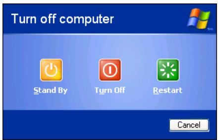
- Click [Stand by].
Method 2: Define the chassis's [Power] button to initiate STR sleep Mode
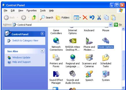
- Open [Control Panel], and then enter [Power Options].
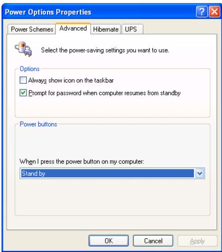
- Select [Advanced] tab. Set the [Power Buttons] option to [Stand by].
Restart your computer to put these settings into effect. Now you will only need to press the [Power] button on the front panel of the chassis when you want to put your computer into STR sleep mode.
Appendix J. Troubleshooting (Need Assistance?)
Motherboard Troubleshooting:
Q & A:
Q: Do I need to clear the CMOS before I use a new motherboard to assemble my new computer system?
A: Yes, we highly recommend that you clear the CMOS before installing a new motherboard. Please move the CMOS jumper from its default 1-2 position to 2-3 for a few seconds, and then back. When you boot up your system for the first time, follow the instructions in the user's manual to load the optimized defaults.
Q: If my systems hang when I update the BIOS or set the wrong CPU parameters, what should I do?
A: Whenever you update the BIOS or if the system hangs due to wrong CPU parameters setting, always clear CMOS jumper before booting up again.
Q: Why the system failed to boot up and nothing was displayed on the screen after I did some over-clocking or non-standard settings inside the BIOS? Is the motherboard dead? Do I need to return it to where I bought from or go through an RMA process?
A: It should not cause hardware or permanent damage to motherboard when BIOS settings were changed from default to over-clocking or non-standard status.
We suggest the following three troubleshooting methods to discharge CMOS data, recover the hardware default status, and then make the motherboard working again. No need to bother returning the motherboard to where you bought from or go through an RMA process.
Step 1. Switch off the power supply unit and then switch it on again after one minute. If there is no power switch on the power supply unit, disconnect its power cord for one minute and then connect it back.
Press and hold the key to enter the BIOS setup page to do the correct settings.
If the situation remains the same, repeat the procedures in Step 1 for three times, or try Step 2.
Step 2. Switch off the power supply unit or disconnect the power cord. Open the chassis cover. Locate the CCMOS jumper near the button battery. Change the jumper position from default 1-2 to 2-3 for one minute to discharge the CMOS data, and then put it back to default 1-2 position.
Close the chassis and switch on the power supply unit or plug in the power cord. Press the power-on button to boot up system. If it works, hit <Del> key to enter the BIOS setup page to do the correct settings.
If the situation remains the same, try Step 3.
Step 3. The same procedure as Step 2, but in the meantime of discharging the CMOS data, pull out ATX power connectors from motherboard and remove the button battery during CMOS discharging.
Q: How can I get a quick response to my request for technical support?
A: Be sure to follow the guidelines as stated in the "Technical Support Form" section of this manual.
If you have a problem during operation, in order to help our technical support personnel quickly determine the problem with your motherboard and give you the answers you need, before filling in the technical support form, eliminate any peripheral that is not related to the problem, and indicate it on the form. Fax this form to your dealer or to the company where you bought the hardware in order to benefit from our technical support. (You can refer to the examples given below)
Example 1:
With a system including: motherboard (with CPU, DRAM, COAST...) HDD, CD-ROM, FDD, VGA CARD, MPEG CARD, SCSI CARD, SOUND CARD, etc. After the system is assembled, if you cannot boot up, check the key components of the system using the procedure described below. First remove all interface cards except the VGA card and try to reboot.
If you still cannot boot up: Try installing another brand/model VGA card and see if the system will start. If it still does not start, note the VGA card model, motherboard model, Bios identification number, CPU on the technical support form (refer to main instructions), and describe the problem in the problem description space provided.
If you can boot up: Insert the interface cards you have removed back into the system, one by one and try to start the system each time you insert a card, until the system will not start. Keep the VGA card and the interface card that caused the problem inserted on the motherboard, remove any other cards or peripheral, and start again. If you still cannot start, note the information related to both cards in the add-on Card space provided, and don't forget to indicate the motherboard model, version, BIOS identification number, CPU (refer to main instructions), and give a description of the problem.
Example 2:
With a system including the motherboard (with CPU, DRAM, COAST...) HDD, CD-ROM, FDD, VGA CARD, LAN CARD, MPEG CARD, SCSI CARD, SOUND CARD, after assembly and after having installed the Sound Card Driver, when you restart the system, when it runs the Sound Card Driver, it resets automatically. This problem may be due to the Sound Card Driver. During the Starting DOS... procedure, press SHIFT (BY-PASS) key, to skip CONFIG.SYS and AUTOEXEC.BAT; edit CONFIG.SYS with a text editor, and in function the line that loads the Sound Card Driver, add a remark REM, in order to disable the Sound Card Driver. See the example below.
CONFIG.SYS:
DEVICE=C:\DOS\HIMEM.SYS
DEVICE=C:\DOS\EMM386.EXE HIGHSCAN
DOS=HIGH, UMB
FILES=40
BUFFERS=36
REM DEVICEHIGH=C:\PLUGPLAY\DWCFGMG.SYS
LASTDRIVE =
Restart the system. If the system starts and does not reset, you can be sure that the problem is due to the Sound Card Driver. Write down the Sound Card model, motherboard model, BIOS identification number on the technical support file (refer to main instructions), and describe the problem in the space provided.
We will show you how to fill the "Technical Support Form".
Main instructions:
To fill in this "Technical Support Form", refer to the step-by-step instructions given below:
- MODEL: Note the model number given in your user's manual.
Example: SI7/SI7-G.
2. Motherboard model number (REV): Note the motherboard model number labeled on the motherboard as "REV:.*".
Example: REV: 1.01 - BIOS ID and Part Number: See the on screen message.
- DRIVER REV: Note the driver version number indicated on the DEVICE DRIVER disk (if any) as "Release .". For example:
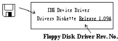
5. OS/APPLICATION: Indicate the operating system and applications you are running on the system.
Example: MS-DOS® 6.22, Windows® 98 SE, Windows® 2000, etc....
6^ .CPU:Indicate the brand and the speed (MHz) of your CPU.
Example:(A) In the "Brand" space, write "Intel"; in the "Specifications" space, write "Pentium® 4 1.9GHz".
- HDD: Indicate the brand and specifications of your HDD(s); specify if the HDD is using IDE1 or IDE2. If you know the disk capacity, indicate it and check ("✓") "☐"; in case you give no indication, we will consider that your HDD is "IDE1" Master.
Example: In the "HDD" space, check the box; in the Brand space, write "Seagate"; in the Specifications space, write "ST31621A (1.6GB)".
- CD-ROM Drive: Indicate the brand and specifications of your CD-ROM drive. Specify if it uses IDE1 or IDE2, and check ("✓") "☐"; in case you give no indication, we will consider that your CD-ROM is "☑IDE2" Master.
Example: In the "CD-ROM drive" space, check the box, in the Brand space, write "Mitsumi", in the Specifications space, write "FX-400D".
- System Memory (DDR SDRAM): Indicate the brand and specifications (DDR DIMM) of your system memory. Such as Density, Description, Module Components, Module Part Number, CAS Latency, and Speed (MHz).
For example: In the Brand space, write "Micron"; in the Specifications space, write: Density: 128MB, Description: SS 16 Megx72 2.5V ECC Gold, Module Components: (9) 16 Megx 8, Module Part Number: MT9VDDT1672AG, CAS Latency: 2, Speed (MHz): 200 MHz.
Please give us the detailed information of your DDR SDRAM module; it will help us to simulate the problems you met.
- ADD-ON CARD: Indicate which add-on cards you are absolutely sure are related to the problem. If you cannot identify the problem's origin, indicate all the add-on cards inserted into your system.
NOTE: Items between the “*” are absolutely necessary.
RAID Troubleshooting
Q & A:
Q: May I use hard drives with different capacity or transfer mode?
A: In order to get optimized performance, we suggest using hard drives with the same model.
Q: How to assign a booting device?
A: You may press Ctrl H to assign a booting device in RAID BIOS (See Appendix G for detailed information).
Q: Why can't I see correct capacity in FDISK utility?
A: It's a well-known issue of Windows® 95/98's FDISK utility. If an IBM 75GB hard disk DTLA 307075 only gets 7768MB in Windows® 95/98's FDISK utility, please contact Microsoft® for a latest version of FDISK utility or download IBM's Disk Manager DiskGo! 2.5 to fix it. For windows® 2000, there is no such a 64GB issue.
http://www.Storage.ibm.com/techsup/hddtech/welcome.htm
Q: How to create a striping and mirror array (RAID 0+1)?
A: You need four HDD drives, every two of them on the same channel/cable build a striping array. Then create a mirror array by these two striping arrays (See Appendix G for detailed information).
- Press <Ctrl> to setup configuration
- Choose item 1 to Create RAID.
- Choose item 1 to set Array Mode as Striping and Mirror (RAID 0 + 1 ).
- Choose item 2 to Select Disk Drives. There are two striping arrays built automatically and you only have to enter twice.
- Choose item 4 to Start Creation Process.
- Press <Esc> to finish setting and leave RAID BIOS.
Q: How to rebuild a mirror array when one of the drives corrupts?
A: You need to delete previous array setting, duplicate the data, and then rebuild a new array setting (See Appendix G for detailed information).
- Press <Ctrl> to setup configuration
- Choose item 2 to Delete Array.
- Choose item 3 to Rebuild Mirror Array.
- Choose sub item 1 to Select Source Disk, the one with data on it.
- Choose sub item 2 to Select Target Disk, the brand new and empty one.
- Choose sub item 3 to Start Duplication Process.
- After duplication process completes, press <Esc> to leave RAID BIOS.
Q: Why I see "NO ROM BASIC SYSTEM HALTED" when booting?
A: There isn't any activated primary partition in you system. Please use FDISK or any other utilities to create/set one.
Do & Don't:
- Do always use the same model drives to achieve best quality and performance. Different firmware has different timing characteristic, thus may somewhat decrease the RAID performance.
- If you have two drives, do connect them on two different channels as master drive please.
- When attach drives to the RAID card, do make sure the master/slave jumper settings are correct please. If there is only one drive on one channel/cable, do set it as master or single drive.
- Do always use 80 conductor cables please.
- Don't connect any ATAPI devices (CD-ROM, LS-120, MO, ZIP, removable HD etc.) on the RAID card please.
- For the best performance result, please do use the Ultra DMA 66/100 Hard Disks.

Technical Support Form

Company Name:

Phone Number:

Contact Person:

Fax Number:

E-mail Address:
| Model | * | BIOS ID # | * |
| Motherboard Model No. | DRIVER REV | ||
| OS/Application | * | ||
| Hardware Name | Brand | Specifications | |
| CPU | * | ||
| HDD IDE1IDE2 | |||
| CD-ROM-Drive IDE1IDE2 | |||
| System Memory | |||
| ADD-ON CARD | |||
Problem Description:
Appendix K. How to Get Technical Support
(From our website) http://www.abit.com.tw
(In North America) http://www.abet-usa.com
(In Europe) http://www.abit.nl
Thank you for choosing ABIT products. ABIT sells all our products through distributors, resellers and system integrators; we have no direct sales to end-users. Before sending email for tech support please check with your resellers or integrators if you need any services, they are the ones who sold you your system and they should know best as to what can be done, how they serve you is a good reference for future purchases.
We appreciate every customer and would like to provide the best service to you. Providing fast service to our customers is our top priority. However we receive many phone calls and a huge amount of email from all over the world. At the present time it is impossible for us to respond to every single inquiry. Therefore it is quite possible that if you send an email to us that you may not receive a response.
We have done many compatibility tests and reliability tests to make sure our products have the best quality and compatibility. In case you need service or technical support, please understand the constraint we have and always check with the reseller who sold the product to you first.
To expedite service, we recommend that you follow the procedures outlined below before contacting us. With your help, we can meet our commitment to provide the best service to the greatest number of ABIT customers:
- Check the Manual. It sounds simple but we have taken a lot of care in making a well-written and thorough manual. It is full of information that doesn't only pertain to motherboards. The CD-ROM included with your board will have the manual as well as drivers. If you don't have either one, go to our Program Download Area of the Website or FTP server.
- Download latest BIOS, software or drivers. Please go to our Program Download area on our Website to check to see if you have the latest BIOS. They are developed over periods of time to fixes bugs or incompatibilities. Also please make sure you have the latest drivers from your peripheral cards makers!
-
Check the ABIT Technical Terms Guide and FAQ on our Website. We are trying to expand and make the FAQs more helpful and information rich. Let us know if you have any suggestions. For hot topics check out our HOT FAQ!
-
Internet Newsgroups. They are a great source of information and many people there can offer help. ABIT's Internet News group, alt.comp.periphs.mainboard.abit, is an ideal forum for the public to exchange information and discuss experiences they have had with ABIT products. Many times you will see that your question has already been asked before. This is a public Internet news group and it is reserved for free discussions. Here is a list of some of the more popular ones:
alt.comp.periphs.mainboard.abit
comp.sys.ibm.pc.hardware.chips
alt.comp.hardware.overlocking
alt.comp.hardware.homebuilt
alt.comp.hardware.pc-homebuilt
- Ask your reseller. Your ABIT authorized distributor should be able to provide the fastest solution to your technical problem. We sell our products through distributors who sell to resellers and stores. Your reseller should be very familiar with your system configuration and should be able to solve your problem much more efficiently than we could. After all, your reseller regards you as an important customer who may purchase more products and who can urge your friends to buy from him or her as well. They integrated and sold the system to you. They should know best what your system configuration is and your problem. They should have reasonable return or refund policies. How they serve you is also a good reference for your next purchase.
- Contacting ABIT. If you feel that you need to contact ABIT directly you can send email to the ABIT technical support department. First, please contact the support team for the branch office closest to you. They will be more familiar with local conditions and problems and will have better insight as to which resellers offer what products and services. Due to the huge number of emails coming in every day and other reasons, such as the time required for problem reproduction, we will not be able to reply to every email. Please understand that we are selling through distribution channels and don't have the resources to serve every end-user. However, we will try to do our best to help every customer. Please also remember that for many of our technical support team English is a second language, you will have a better chance of getting a helpful answer if your question can be understood in the first place. Be sure to use very, simple, concise language that clearly states the problem, avoid rambling or flowery language and always list your system components. Here is the contact information for our branch offices:
North America and South America:
ABIT Computer (U.S.A.) Corporation
45531 Northport Loop West,
Fremont, California 94538, U.S.A.
Tel: 1-510-623-0500
Fax: 1-510-623-1092
sales@abit-usa.com
technical@abit-usa.com
Germany, Benelux (Belgium, Netherlands, Luxembourg), Denmark, Norway, Sweden, Finland, and Switzerland:
AMOR Computer B.V. (ABIT's European Office)
ABIT Computer (Japan) Co. Ltd.
Fax: 81-3-5396-5110
http://www.ubit4u.jp
Russia:
ABIT Computer (Russia) Corporation Ltd.
Fax: 7 (095) 937 8237
http://www.abit.ru
U.K. and Ireland:
ABIT Computer (U.K.) Corporation Ltd.
Unit 3, 24-26 Boulton Road,
Stevenage, Herts SG1 4QX, U.K.
Tel: 44-1438-228888
Fax: 44-1438-226333
sales@abitcomputer.co.uk
technical@abitcomputer.co.uk
Austria, Czech, Romania, Bulgaria,
Yugoslavia, Slovakia, Slovenia, Croatia,
Bosnia and Serbia:
Asguard Computer Ges.m.b.H
Schmalbachstrasse 5,
A-2201 Gerasdorf/wien, Austria
Tel: 43-1-7346709
Fax: 43-1-7346713
asguard@asguard.at
Shanghai:
ABIT Computer (Shanghai) Co. Ltd.
Tel: 86-21-6235-1829
Fax: 86-21-6235-1832
http://www.abit.com.cn
France:
ABIT Computer France SARL
4, Place La Defense,
92974 Paris La Defense cedex, France
Fax: 33-1-5858-0047
http://www.abit.com.tw
All other territories not covered above please contact Taiwan Head Office:
When contacting our headquarters please Note we are located in Taiwan and we are 8+ GMT time. In addition, we have holidays that may be different from those in your country.
ABIT Computer Corporation
No.323, YangGuang St., Neihu, Taipei, 114, Taiwan
Tel: 886-2-8751-8888
Fax: 886-2-8751-3381
sales@abit.com.tw
market@abit.com.tw
technical@abit.com.tw
http://www.abit.com.tw
- RMA Service. If your system has been working but it just stopped, but you have not installed any new software or hardware recently, it is likely that you have a defective component. Please contact the reseller from whom you bought the product. You should be able to get RMA service there.
- Reporting Compatibility Problems to ABIT. Because of tremendous number of email messages we receive every day, we are forced to give greater weight to certain types of messages than to others. For this reason, any compatibility problem that is reported to us, giving detailed system configuration information and error symptoms will receive the highest priority. For the other questions, we regret that we may not be able to reply directly. But your questions may be posted to the Internet news group in order that a larger number of users can have the benefit of the information. Please check the news group from time to time.
- The information listed below are some chipset vendors' WEB site addresses for your reference:
HighPoint Technology Inc.'s WEB site: http://www.highpoint-tech.com/
Intel's WEB site: http://www.intel.com/
Silicon Image's WEB site: http://www.siimage.com/

- Copyright and Warranty Notice
- Table Of Contents
- Chapter 2. Hardware Setup 2-1
- Chapter 3. BIOS Setup 3-1
- Appendix A. Install SiS Chipset Driver. 4
- Appendix B. Install SiS IDE Driver
- Appendix C. Install Audio Driver..
- Appendix D. Install LAN Driver....
- Appendix E. Install SiS USB 2.0 Driver..
- Appendix F. Install Serial ATA RAID Driver..
- Appendix G. BIOS Update Guide.. .G-1
- Appendix H. Hardware Monitoring (The Winbond Hardware Doctor Utility)...H-1
- Appendix I. Installation Guide for Suspend to RAM 1-1
- Appendix J. Troubleshooting (Need Assistance?)............................................J-1
- Appendix K. How to Get Technical Support.
- SI7 系列快速安装指引
- YcTaHOBKa MaTePnHckoI IaTbI B KOpNvC
- UcTaHOBka MoVJIeI NaMHTN
- Pa3bEmbl, HepeKJIooYaTeHn H aIaIITepbl
- IoiKJIIOUeHHe Ka6eJeI IHTaHHN K pa3bEmAM ATX12V
- Hacrpoika BIOS
- 1-1. Features & Specifications
- CPU
- Chipset
- Memory
- AGP
- LAN
- Serial ATA 150
- Media XP (Optional)
- USB 2.0
- 9.IEEE1394
- Audio
- System BIOS
- Internal I/O Connectors
- Back Panel I/O
- Miscellaneous
- Order Information
- 1-2. Layout Diagram
- Chapter 2. Hardware Setup
- 2-1. Install The Motherboard
- 2-2. Install Pentium® 4 CPU and Heatsink Supporting-Base
- 2-3. Install System Memory
- 2-4. Connectors, Headers and Switches
- (1).ATX Power Input Connectors [ATXPWR1, ATX12V1]
- (2). FAN Connectors [CPUFAN1, SYSFAN1, AUXFAN1]
- (3). CMOS Memory Clearing Header [CCMOS1]
- (4). Front Panel Audio Connection Header [FP-AUDIO1]
- (5). Additional USB Port Headers [FP-USB1, FP-USB2]
- (6). Additional IEEE1394 Port Headers [FP-1394-1, FP-1394-2]
- (7). Front Panel Switches & Indicators Headers [FPIO1]
- (8). System Management Bus Header [SMB1]
- (9). Internal Audio Connectors [CD1, AUX1]
- (10). Accelerated Graphics Port Slot [AGP1]
- (11). Floppy Disk Drive Connector [FDC1]
- (13). Serial ATA Connectors [SATA1, SATA2]
- (14). POST Code Display [U32]
- (15). Onboard Switches [FORWARD, BACK, PS ON, RESET]
- (16). Status Indicators [D17, D14, D15, D18]
- Chapter 3. BIOS Setup
- Press DEL to run setup
- 3-1. SoftMenu Setup Features
- Processor Type:
- Processor Speed:
- Cache Size:
- CPU Operating Speed:
- User Define:
- CPU Front Side Bus Frequency:
- CPU Ratio Selection:
- Estimated new CPU clock:
- CPU FSB/2xMREF/AGP/PCI ratio:
- Fixed AGP/PCI frequency:
- 2xMREF/RDRAM ratio:
- New FSB/DRAM/AGP/PCI clock:
- CPU core voltage:
- RDRAM voltage:
- AGP slot voltage:
- 3-2. Standard CMOS Features
- System Date:
- System Time:
- Floppy Driver A / Floppy Driver B:
- IDE Primary Master/Slave and IDE Secondary Master/Slave:
- Type:
- Cylinders:
- * Heads:
- * Write Precompensation:
- * Sectors:
- Maximum Capacity:
- LBA (Logical Block Addressing) mode:
- Block Mode:
- Fast Programmed I/O Modes:
- Bit Transfer Mode:
- Primary Display:
- 3-3. Advanced BIOS Features
- Quick Boot:
- How to use the Quick Boot function?
- Boot Device Priority:
- Try Other Boot Other Devices:
- BootUp Num-Lock:
- PS/2 Mouse Support:
- Password Check:
- Boot To OS/2:
- System BIOS Cacheable:
- Video BIOS Cacheable:
- 3-4. Advanced Chipset Features
- DRAM Data Integrity Mode:
- Synchronous Mode Select:
- Channel Mode Select:
- * MPS Revision:
- Auto Turn Off Pci Clock Pin:
- 3-5. Power Management Features
- ACPI Standby State:
- Initialize VGA BIOS By S3:
- Power Switch Type:
- Restore on AC/Power loss:
- Wake Up Events:
- Keyboard PowerOn Function:
- Resume by USB:
- Wake Up by PS2 Mouse:
- PS2 MOUSE Wakeup Mode Select:
- Wake Up by PME:
- Wake Up by Modem Ring:
- Wake Up by RTC:
- \*RTC Alarm Date:
- \*RTC Alarm Hour:
- \*RTC Alarm Minute:
- \*RTC Alarm Second:
- 3-6. PnP/PCI Configurations
- Plug and Play Aware O/S:
- PCI Latency Timer (PCI Clocks):
- Primary Graphics Adapter:
- Allocate IRQ to VGA:
- PIRQ 0 Use IRQ No.~PIRQ 3 Use IRQ No.:
- NOTE:
- \* IRQ Resources:
- \* DMA Resources:
- 3-7. Integrated Peripherals
- OnBoard Super I/O Devices:
- OnBoard FDC:
- Onboard Serial PortA / Onboard Serial PortB:
- * Serial PortB Mode:
- * IR Pin Select:
- Onboard Parallel Port:
- * Parallel Port Mode:
- * EPP Version:
- * Parallel Port IRQ:
- * Parallel Port DMA Channel:
- OnBoard PCI Devices:
- Serial ATA RAID
- * Serial ATA RAID boot ROM
- LAN Controller
- * LAN boot ROM
- SiS OnChip IDE Controller:
- PCI IDE BusMaster:
- Onboard PCI IDE:
- SiS OnChip USB Controller:
- USB Function:
- USB 2.0 Supports:
- USB KB/Mouse/FDD Legacy Support:
- SiS OnChip 1394 Controller:
- SiS OnChip Audio Controller:
- 3-8. PC Health Status
- FAN Fail Warning:
- CPU Warning Temperature:
- All Voltages, Fans Speed and Thermal Monitoring:
- 3-9. Set Password
- 3-10. Load Optimized Defaults
- 3-11. Load Fail-Safe Defaults
- 3-12. Save & Exit Setup
- 3-13. Exit Without Saving
- Appendix A. Install SiS Chipset Driver
- Click [Next].
- Click [Next].
- Appendix C. Install Audio Driver
- Appendix D. Install LAN Driver
- For SI7:
- For SI7-G:
- Appendix E. Install SiS USB 2.0 Driver
- For Windows XP:
- For Window 2000:
- Appendix F. Install Serial ATA RAID Driver
- BIOS Setup for Serial ATA RAID
- RAID Configuration Utility Menu
- Main Menu
- Option 1 Create RAID set
- - Array Mode:
- Option 2 Delete RAID set
- Option 3 Rebuild Mirrored set
- Option 4 Resolve Conflicts
- Appendix G. BIOS Update Guide
- [c:\]format a:/s
- A:\>amiflash sx7_89.rom
- Note
- Appendix H. Hardware Monitoring (The Winbond Hardware Doctor Utility)
- Appendix I. Installation Guide for Suspend to RAM
- How to use the STR function:
- Appendix J. Troubleshooting (Need Assistance?)
- Motherboard Troubleshooting:
- Q & A:
- Q: How can I get a quick response to my request for technical support?
- Example 1:
- Example 2:
- Main instructions:
- RAID Troubleshooting
- Do & Don't:
- Technical Support Form
- Appendix K. How to Get Technical Support
Brand : ABIT
Model : SI7
Category : Motherboard