
E 3 RM - Inverter INFOSEC - Free user manual and instructions
Find the device manual for free E 3 RM INFOSEC in PDF.
| Product type | Online double conversion UPS (On Line) |
| Brand | INFOSEC |
| Model | E 3 RM (versions 750, 1000, 1500, 2000, 3000 VA) |
| Technology | High frequency, high density, pure sine wave |
| Power | 750 VA / 1000 VA / 1500 VA / 2000 VA / 3000 VA |
| Input voltage | 110-127 V or 220-240 V configurable |
| Output voltage | 110/120/127 V or 220/230/240 V configurable |
| Frequency | 50/60 Hz ± 5 Hz (normal mode) |
| Internal battery | According to model: 12V/7Ah (E3750), 12V/9Ah (E31000), 12V/5Ah (E33000) or external pack for E31500/E32000 |
| Battery run time at full load | 5 minutes minimum (with additional battery packs for models 1500/2000) |
| Recharge time | 4 hours to 90% after full discharge (3 hours for E33000) |
| Dimensions (W × D × H) | E3750/1000: 235 × 383 × 86.2 mm E31500/2000: 217 × 413.5 × 86.5 mm E33000: 438 × 582 × 86.2 mm |
| Weight | From 8.6 kg (E3750) to 31.5 kg (E33000) |
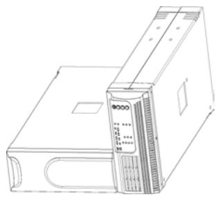
| Mounting | Rack 2U (19 inches) or tower, 2-in-1 design |
| Communication interfaces | USB, RS-232, dry contacts; optional SNMP slot |
| Protections | Overload, short circuit, excessive temperature, overvoltage, telephone/Ethernet line |
| Included software | UPSsurf Control (automatic shutdown, network management) |
| Noise level | < 45 dB |
| Operating temperature | 0 to 40 °C |
| Relative humidity | 20 to 80 % without condensation |
| Standards | CE (safety/manufacturing) |
Frequently Asked Questions - E 3 RM INFOSEC
User questions about E 3 RM INFOSEC
0 question about this device. Answer the ones you know or ask your own.
Ask a new question about this device
Download the instructions for your Inverter in PDF format for free! Find your manual E 3 RM - INFOSEC and take your electronic device back in hand. On this page are published all the documents necessary for the use of your device. E 3 RM by INFOSEC.
USER MANUAL E 3 RM INFOSEC
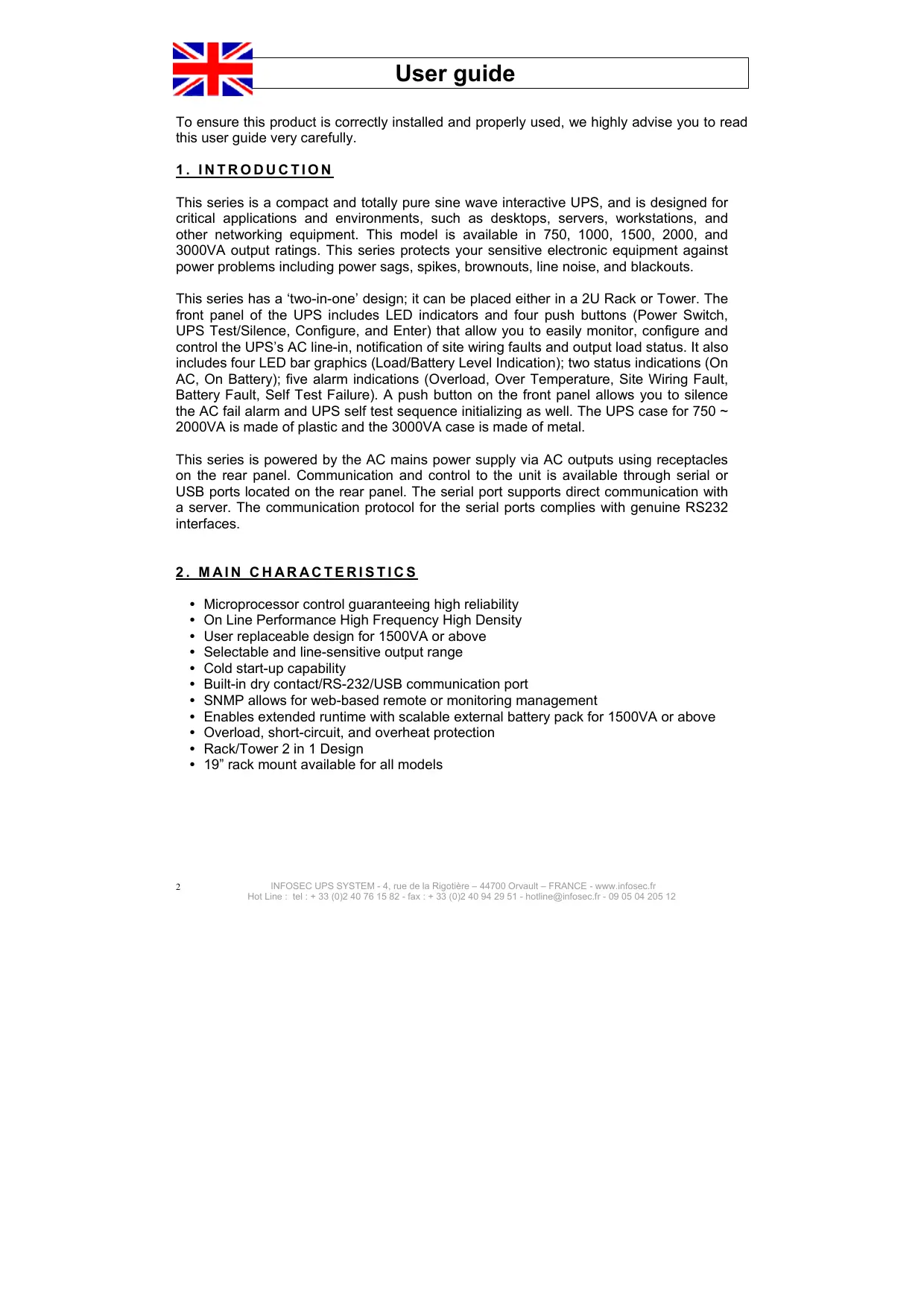
To ensure this product is correctly installed and properly used, we highly advise you to read this user guide very carefully.
1. INTRODUCTION
This series is a compact and totally pure sine wave interactive UPS, and is designed for critical applications and environments, such as desktops, servers, workstations, and other networking equipment. This model is available in 750, 1000, 1500, 2000, and 3000VA output ratings. This series protects your sensitive electronic equipment against power problems including power sags, spikes, brownouts, line noise, and blackouts.
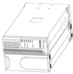
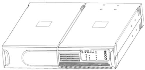
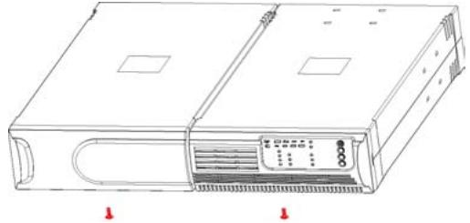
This series has a 'two-in-one' design; it can be placed either in a 2U Rack or Tower. The front panel of the UPS includes LED indicators and four push buttons (Power Switch, UPS Test/Silence, Configure, and Enter) that allow you to easily monitor, configure and control the UPS's AC line-in, notification of site wiring faults and output load status. It also includes four LED bar graphics (Load/Battery Level Indication); two status indications (On AC, On Battery); five alarm indications (Overload, Over Temperature, Site Wiring Fault, Battery Fault, Self Test Failure). A push button on the front panel allows you to silence the AC fail alarm and UPS self test sequence initializing as well. The UPS case for 750 2000VA is made of plastic and the 3000VA case is made of metal.
This series is powered by the AC mains power supply via AC outputs using receptacles on the rear panel. Communication and control to the unit is available through serial or USB ports located on the rear panel. The serial port supports direct communication with a server. The communication protocol for the serial ports complies with genuine RS232 interfaces.
2. MAIN CHARACTERISTICS
- Microprocessor control guaranteeing high reliability
- On Line Performance High Frequency High Density
- User replaceable design for 1500VA or above
- Selectable and line-sensitive output range
Cold start-up capability
Built-in dry contact/RS-232/USB communication port
SNMP allows for web-based remote or monitoring management - Enables extended runtime with scalable external battery pack for 1500VA or above
Overload, short-circuit, and overheat protection
Rack/Tower 2 in 1 Design
19" rack mount available for all models
3. SAFETY INSTRUCTIONS - Security
SAVE THESE INSTRUCTIONS - This Manual Contains Important Instructions that should be followed during Installation and Maintenance of the UPS and Batteries.
WARNING: Do not attempt to repair or service this UPS. It manages high voltages which could cause and run the risk of electrical shock. Even if this UPS is disconnected from the electrical mains power, there may still be potentially dangerous voltage via the battery. All maintenance and battery replacement should be performed by qualified service personnel only.
- This UPS should be set up in a room with adequate airflow and free of contamination. Install or operate it in a clean and indoor environment, free from moisture, flammable liquids, and direct sunlight. Ambient temperature range must be between 0^ and 40^ (32°F to 104°F).
- This UPS is designed for Commercial/Industrial use only. It is not intended for use with life support systems or other designated "life-critical" medical devices.
- Do not remove the input power cord when this UPS is turned on. This deactivates the safety ground link and the equipment connected to the UPS.
- Turn off the UPS and disconnect the input power cord before proceeding to replace the battery.
-
Battery contains high short-circuit current. Replacing or servicing the battery should be performed and supervised by qualified service personnel aware of the required precautions.
-
Remove watches and jewelry
- Use tools with insulated handles
- Wear rubber gloves and boots.
- Do not lay tools or metal parts on top of batteries.
-
Disconnect charging source prior to connecting or disconnecting battery terminals.
-
When replacing the batteries, use the appropriate replacement battery kits: it is compulsory to use of same number and type of battery.
- Do not open or damage the battery in any way. Released electrolyte may be toxic and harmful to skin and eyes.
- Do not dispose of the battery in a fire. It may explode. Proper disposal of the battery is required. Please refer to your local laws and regulations for disposal requirements.
- To reduce the risk of fire, use only No. 26 AWG or larger telecommunication line cord.
-
This UPS manages high voltages. Do not run the risk of electric shock by removing the cover. There are no user replaceable parts inside this UPS. Please contact your local dealer or distributor for any maintenance operations.
-
To reduce the risk of fire, connect only to a circuit provided with 30 amperes maximum (for 3000VA/120Vac) and 20 amperes maximum (for 2000VA/120Vac and below models) branch circuit overcurrent protection in accordance with the National Electrical Code, ANSI/NFPA 70.
- This pluggable type A equipment with battery already installed by the supplier is operator installable and may be operated by laymen.
- During the installation of this equipment you should ensure that the sum of the leakage currents of the UPS and the connected loads does not exceed 3.5mA .
- Attention, this UPS uses potentially hazardous voltages. There is a risk that output sockets remain live, via the battery, after the UPS has been disconnected from the mains power supply. The battery should therefore disconnected from the plus and minus pole when maintenance or servicing inside the UPS is necessary.
- The mains socket outlet that supplies the UPS should be installed near the UPS and be easily accessible.
DESCRIPTION OF COMMONLY USED SYMBOLS:
| Symbol & Description | |
| Symbol | Description |
| A | Alert you to pay special attention |
| A | Caution of high voltage |
| ~ | Alternating current source(AC) |
| --- | Direct current source(DC) |
| ⊕ | Protective ground |
| Recycle | |
| × | Keep UPS in a clean area |
4. STORAGE INSTRUCTIONS
The UPS should be stored with its battery fully recharged. Storage temperatures above 20^ should be avoided as this will significantly shorten battery life. The UPS should be recharged once every 3 months. This is done by leaving it connected to the mains power supply for 24 hours. Batteries kept in storage should be recharged every 3 months, failure to do so could result in battery damage.
5. AFTER SALES SERVICE
IMPORTANT!
When calling the After-Sales Department, please have the following information ready, it will be required regardless of the problem: UPS model, serial number and date of purchase.
Give an accurate description of the problem including the following details: type of equipment powered by the UPS, indicator led status, alarm status, installation and environmental conditions.
You will find the technical information you require on your guarantee or on the identification plate on the back of the unit. If convenient you may enter the details in the following box.
| Model | Serial number | Date of purchase |
| E3 .... VA |
! Please keep the original packaging. It will be required in the event the UPS is returned to the After-Sales Department.
6.DESCRIPTION
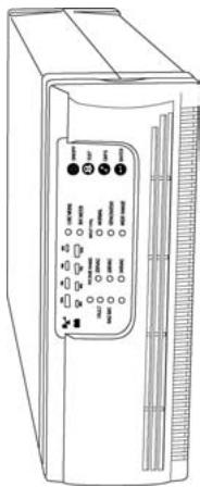
FRONT PANEL
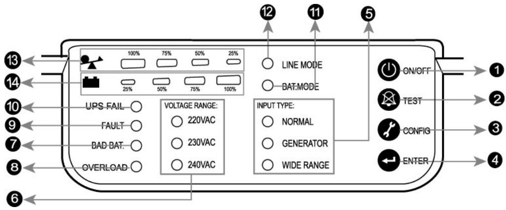
| No. | Function | Description |
| 1 | Switch | ON/OFF |
| 2 | Switch | Self-Test/ Alarm Silence |
| 3 | Switch | Config |
| 4 | Switch | Enter |
| 5 | LED | Input Type (Operating Mode) |
| 6 | LED | Voltage Range |
| 7 | LED | Bad Battery |
| 8 | LED | Overload |
| 9 | LED | Fault |
| 10 | LED | UPS Fail (or Site Fault) |
| 11 | LED | Battery Mode |
| 12 | LED | Line Mode |
| 13 | LED | Capacity of Load |
| 14 | LED | Capacity of Battery |
1. Power Switch:
- To turn on the UPS, press and hold the button for more than three seconds
- To turn off the UPS, press and hold this button until you hear the UPS beep ceases.
2. UPS Test/ Alarm Silence:
-
If the battery is fully charged and the UPS is in AC line mode, to perform self-test function, press and hold the button for five seconds.
-
To disable the alarm buzzer, press this button for a second. Each time a new alarm event is encountered and the alarm sounds, press this button to turn it off.
NB: If unable to disable the alarm buzzer, the cause may be any of the following: Low Battery, Overload, Fan Failed, Fan Fault Time Out, Over Temperature.
3. Configure:
To reconfigure the internal UPS setup options, follow the procedure as below:
Step 1: Press the Configure button for more than three seconds. Then the UPS will transfer from configure mode to "output voltage mode".
Step 2: Press the Configure button for more than one second, the UPS allows you to select the "output voltage mode" one by one.
Step 3: After selecting the mode, press the Enter button for more than three seconds, the "output voltage mode" is configured.
Step 4: UPS will automatically transfer from configure mode to "operating mode".
Step 5: Press the Configure button for more than one second; the UPS will allow you to select the "operating mode" one by one.
Step 6: After selecting the mode, press the button for more than three seconds, the "operating mode" is configured.
4. Enter:
Press the button after you choose the mode.
5. Input Type (Operating Mode) LED:
INPUT TYPE:
NORMAL
GENERATOR
WIDE RANGE
- Normal mode: The Yellow LED indicator will be on during normal mode, the UPS accepts AC input voltage range from +/-20% .
- Generator: No change to voltage window. However, the low frequency transfer point is changed to 40Hz and there is no limitation for the high frequency transfer point.
- Wide range: The LED indicator will come on, the UPS accepts AC input voltage range from -30% +20% .
6. Voltage Range (Output Voltage Mode) LED:
UPS Output voltages selection: 110VAC/120VAC/127VAC or 220VAC/230VAC/240VAC.
VOLTAGE RANGE:
110VAC
120VAC
127VAC
VOLTAGE RANGE:
220VAC
230VAC
240VAC
7. Bad Battery LED:
The LED indicator will come on when the battery fails or if the battery is disconnected. The LED will flash every two seconds. Please check your battery connection; replace the battery or contact your local dealer for a battery replacement kit.
8. Overload LED:
The LED indicator will come on when the UPS overload times out.
9. Fault LED:
The LED indicator will come on when the UPS fails/overload is timed out /or short-output.
10. UPS FAIL LED (or SITE FAULT LED):
- UPS FAIL LED: the LED indicator will come on when the power module of the UPS fails.
- SITE FAULT LED: the LED indicator will come on when the UPS is plugged into an improper utility.
NB: The "SITE FAULT" function is only available for 120Vac models.
11. BAT Mode LED (Battery Mode):
The LED indicator will flash every five seconds when the UPS is providing battery power to your equipment. On the other hand, the LED indicator gives you a warning which will flash every two seconds when the battery is low.
12. Line Mode LED:
The line LED indicator comes on when the AC source is present.
When the LED indicator is flashing, the UPS is either in AVR mode or off while AC power is active.
13. Capacity of Load LED:
- Load Indicator: The LED indicator and the load level indicator will illuminate to show the load level.
- Load Level Indicator:


There are four LED bar indicators to show the percentage of UPS load capacity being used by the protected equipment. The greater the load, the more LED indicators illuminated. Each LED indicator designates 25% of the UPS output capacity. Please see the following load level:
0 25% : 1^st LED indicator
26% 50% :1^st and 2^nd LED indicators
51% 75% : 1^st, 2^nd , and 3^rd LED indicators
76% 100% : All four LED indicators will be on
14. Capacity of Battery LED:
-
Battery Indicator: The LED indicator and battery level indicator will come on to show battery level.
-
Battery Level Indicator:

There are four LED bar indicators to show the amount of battery capacity remaining. The higher the battery capacity, the more LED indicators illuminated. Each LED indicator designates a 25% capacity level. Please see the following capacity level:
0 25% : 4^th LED indicator
26% 50% : 3^rd and 4^th LED indicators
51% 75% 2^nd , 3^rd , and 4^th LED indicators
76% 100% : All four LED indicators will be on
Indicator Condition
| Condition | Alarm |
| Utility Mode (AC Mode) | Line LED on |
| Backup Mode (Power Failure) | Flashing every four seconds |
| Site Fault | Site fault LED on (For 120VAC Models) |
| 4 segment LED bar: 0~25%: 4thLED on; 26~50%: 3rdand 4thLEDs on; 51~75%: 2nd, 3rd, and 4thLEDs on; 76~100%: all of 4 LEDs on | |
| UPS Fault | Fault LED on |
| Overload | Overload LED on |
| Low Battery | Battery LED flashing every second |
Audible Alarm Condition
| Condition | Alarm |
| Backup Mode (Power Failure) | Sounding every four seconds |
| Low Battery | Sounding every second |
| UPS Fault | Sounding continuously |
| Overload | Sounding every second |
| Battery Replacement | Sounding every second |
E³ 750 / E³ 1000
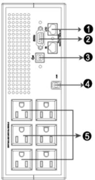
E^3 1000 NEMA
E^3 750 NEMA
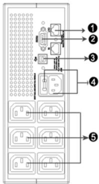
E^3 1000 IEC
E^3 750 IEC
Table describing the rear panel for NEMA and IEC models
| No. | Function | |
| NEMA model (110/120/127Vac) | IEC model (220/230/240Vac) | |
| 1 | Modem/Network Surge Protection | |
| 2 | RS232 / Dry-Contact Communication Port | |
| 3 | USB Communication Port | |
| 4 | AC Input Power cord | AC Input & Protection |
| 5 | AC Output NEMA | AC Output IEC |
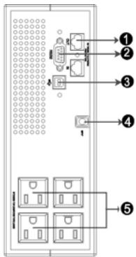
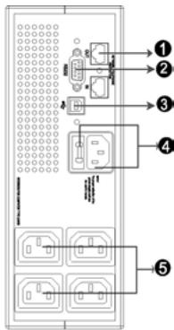
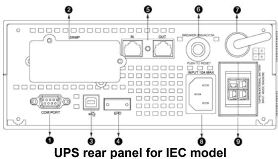
E³ 1500 / E³ 2000
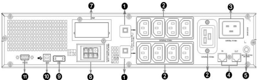
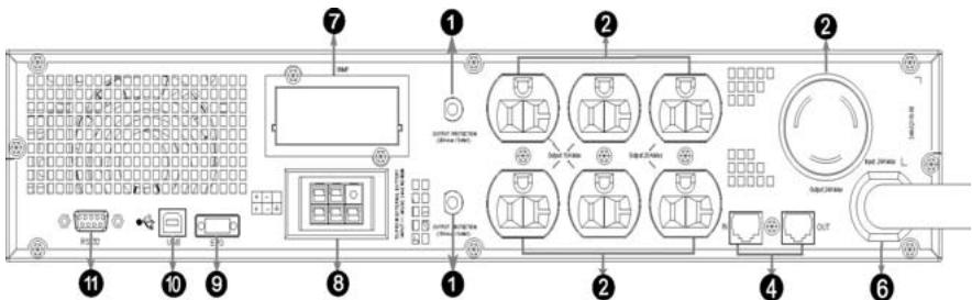
1. UPS Rear Panel:
The UPS rear panel pictures for IEC and NEMA models are shown as below:
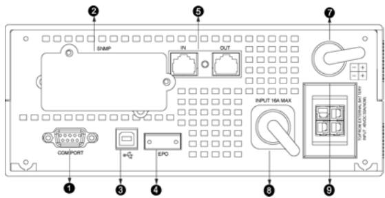
UPS rear panel for NEMA model
Table describing the rear panel for NEMA and IEC models
| No. | Function | |
| NEMA model (110/120/127Vac) | IEC model (220/230/240Vac) | |
| 1 | RS232 / Dry-Contact Communication Port | |
| 2 | SNMP Port | |
| 3 | USB Port | |
| 4 | EPO | |
| 5 | Modem/Network Surge Protection | |
| 6 | N/A | Input Breaker |
| 7 | AC Output | |
| 8 | AC Input | AC Input |
| 9 | External Battery Connector | |
2. Battery Pack Rear Panel:
The battery pack rear panel pictures for IEC and NEMA models are shown below. The battery pack can be placed on top of, beside or nearby the UPS.
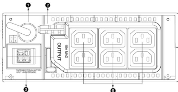
Battery Pack Rear panel for IEC model
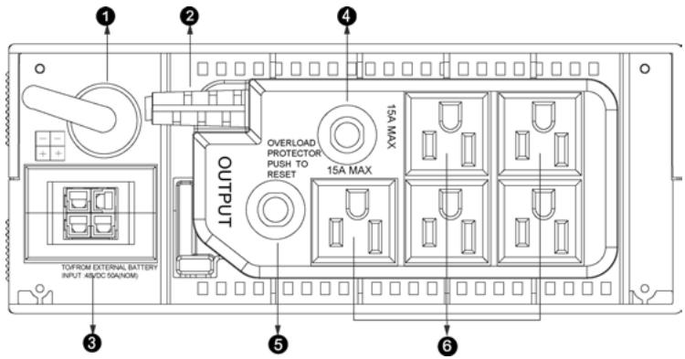
Battery Pack Rear panel for NEMA model
Table describing the rear panel for NEMA and IEC models
| No. | Function | |
| NEMA model (110/120/127Vac) | IEC model (220/230/240Vac) | |
| 1 | Battery Output Power Cord | |
| 2 | AC Output | |
| 3 | External Battery Connector | |
| 4 | Output Breaker | N/A |
| 5 | Output Breaker | N/A |
| 6 | Output Receptacles | Output Receptacles |
E3 3000
Rear panel for IEC model
Rear panel for NEMA model
Table describing the rear panel for NEMA and IEC models
| No. | Function | |
| NEMA model (110/120/127Vac) | IEC model (220/230/240Vac) | |
| 1 | Output Breaker | |
| 2 | AC Output | |
| 3 | AC Input | |
| 4 | Modem/Network Surge Protection | Modem/Network Surge Protection |
| 5 | Input Breaker | N/A |
| 6 | Input Power Cord | N/A |
| 7 | SNMP Slot | SNMP Slot |
| 8 | External Battery Connector | External Battery Connector |
| 9 | EPO | EPO |
| 10 | USB Port | USB Port |
| 11 | RS232 / Dry-Contact Communication Port | |
7. INSTALLATION AND OPERATION
1. Inspecting the Equipment
Inspect the UPS upon receipt. If the UPS has been damaged during shipment, notify the carrier and dealer immediately
2. Position
This UPS should be installed in a room with adequate airflow and free of contamination. Locate it in a clean and indoors environment, free from moisture, flammable liquids, and direct sunlight. Maintain a minimum clearance of 4 inches (100mm); the ambient temperature must be between 0^ and 40^ (32°F to 104°F), and relative humidity between 20% and 80% (non-condensing).
CAUTION: The long term use at an ambient temperature in excess of 25^ would reduce battery life. In addition, place the UPS unit at least 20cm away from the monitor to avoid interference.
3. Charging
This UPS is shipped from the factory with its internal battery fully charged; however, some charge may be lost during shipping. The battery should be recharged prior to use. Plug the UPS into an appropriate power supply and allow the UPS to charge for at least 4 hours.
4. Load Connection
Connect one load-related device to each of the power receptacles supplied at the rear of the UPS.
5. Modem/Phone line Connection
Plug the incoming telephone line into the "In" socket at the back of the UPS. Use on telephone line cable and plug one end of the telephone line cable into the "Out" socket at the back of the UPS. Plug the other end into the modem input socket.
6. DC Start Function
DC Start Function enables the UPS to be started up when AC utility power is not available (if the battery is full charged). Simply press the On/Off switch to turn on the UPS.
7. Turn On/Off
To turn on/off the UPS, press and hold the on/off switch for at least three seconds.
8. UPS Setup
All model series are designed for use in a tower or rack. They can be installed as a 19-inch equipment rack, and the 3000VA can be placed in a tower (with optional stand) as well. Please follow the instructions for Tower Setup or Rack-Mount Setup.
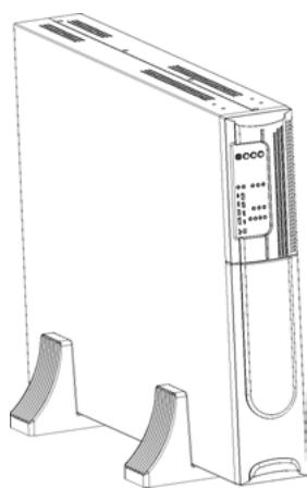
9. Tower Setup
This series can be placed horizontally and vertically. The 3000VA model is designed in a rack itself. As a tower, it is provided with UPS stand to stabilize the UPS when it is positioned vertically. The UPS stand must be attached to the bottom of the tower.
Tower form
1500/2000VA
The UPS and its battery pack can be displayed in three types of towers
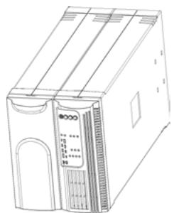
Tower form setup
- Slide the UPS vertically and put two UPS stands at the end of the tower.
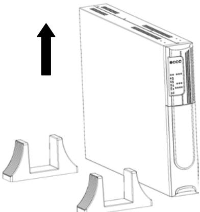
- Carefully place the UPS in the two stands.
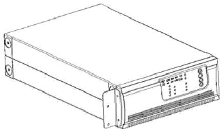
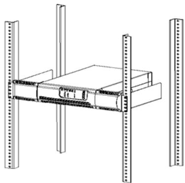
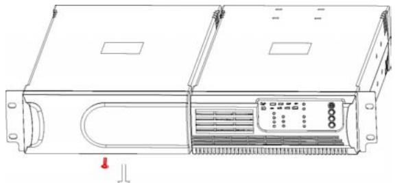
10. Rack-Mount Setup
The 750/1000/1500/2000VA and 3000VA (optional) can be installed in 19" racks. And the UPS and external battery enclosure need 2Us of free space. Use the following procedure to install the UPS in a rack.
- Install the rack-mounting rails using the screws provided to tighten the rack enclosure.
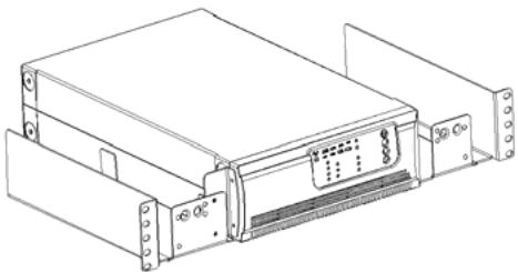
- Insert the UPS into the slide assemblies and lock it in the rack enclosure.
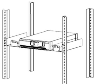
- Add the front panels for both sides. The load can be connected.
- The UPS and its battery pack can be placed in rack form
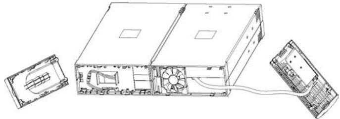
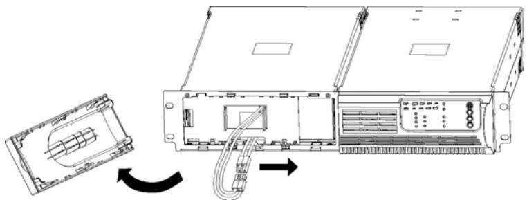
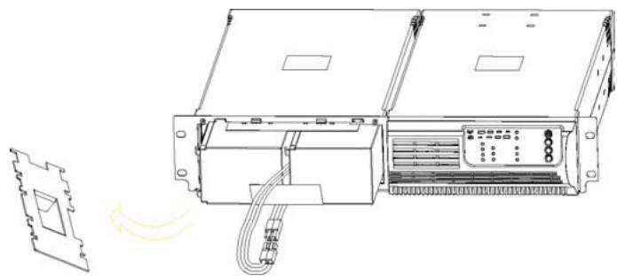
- Place the UPS on a flat and a clean surface with the front side of the UPS facing you.
- Disconnect the cable and its battery pack from the UPS.
- Loosen the screws and remove the UPS and its battery pack cover from the unit
- Pull off the two covers as shown below.
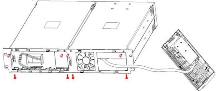
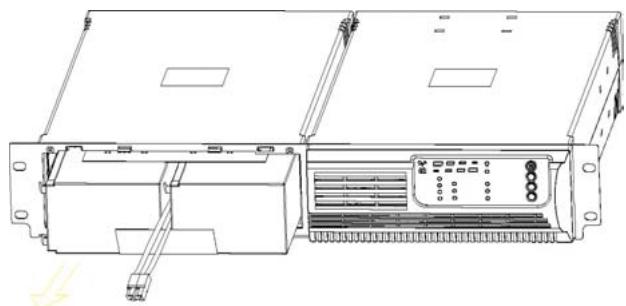
- Align the mounting bracket with the screw holes on the each side of the UPS and its battery pack, and secure with the screws provided.
- Reinstall the UPS and its battery pack covers.
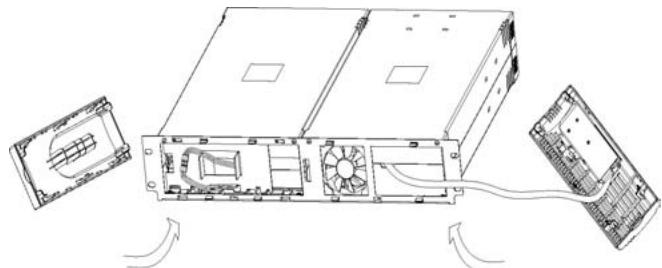
- Tighten all screws in the front panels and setup the rack-mount to finish the front panel of the UPS.
- Align two small mounting brackets at the rear of the UPS and its battery pack and secure with the supplied screws. Install Output receptacles to the rear panel of the UPS.
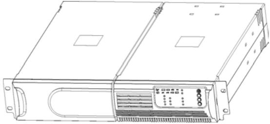
- The setup of the UPS is now finished, you can install and connect it.
- 2 battery packs can be joined to constitute a rack system
3000VA
Install the 3000VA series into the 19" rack as shown below.
- Turn on the UPS and connect the load.
- After installing the UPS in rack, the load may be connected. Make sure the load equipment is turned off, and then plug all loads into the output receptacle properly protected by a circuit breaker fuse in accordance with national and local electrical codes.
11. Emergency Power Off (EPO) set up
The 1500/2000VA and 3000VA include EPO port that allows an immediate power shut down in the protected equipment and does not follow the shutdown procedure from any power management software.
Note: When the EPO switch is reset, the equipment will not return to battery power until the UPS is manually restarted. If the power switch to turn off the UPS after EPO is pressed, the UPS remains in Standby mode until pressing the power switch to turn on the UPS again.
Follow the procedure below to install the EPO switch.
- Check the UPS is turned off.
-
Remove the EPO connector from the EPO port on the rear panel of the UPS
-
Connect isolated, normally-open, dry contacts (rated to handle 60Vdc maximum, 30Vac RMS maximum, and 20mA maximum) across the EPO device to Pin 1 and Pin 2. Use non-shield wiring, size 18-22 AWG (0.75 mm² - 0.3 mm²).
- Reconnect the EPO connector to the EPO port.
- Verify that the externally-connected EPO switch is not on to enable power to the UPS output receptacles.
- Plug in the UPS, then press power switch button to turn on the UPS.
- Activate the external EPO switch to test the EPO function
- De-activate the external EPO switch and restart the UPS.
12. UPSurf Control
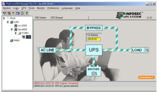
UPSsurf Control, the automatic shutdown software (included) allows the UPS to be managed from a computer.
UPSsurf Control is a brand new UPS monitoring software, which provides a user-friendly interface to monitor and control your UPS. This unique software provides safe auto shutdown for multi-computer systems in the event of power failure. With this software, users can monitor and control any UPS on the same LAN no matter how far away they are.
When installing all required files from the Internet, enter the serial No: 511C1-01220-0100-478DF2A to install the software.
When your computer restarts, the UPSsurf Control software will appear as a green plug icon located in the system tray, near the clock.
8. ADDITIONAL BATTERY INSTALLATION SET UP
The 750/1000 VA & 3000VA models feature internal batteries inside the UPS. The 1500/2000VA models have no internal battery and require an external battery pack.
The 1500/2000VA and 3000VA models include an external battery port to provide additional battery runtime.
Caution: While adding a battery pack, connection of the battery cable to the external battery port may cause sparks.
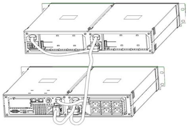
1500/2000VA
There are two external battery ports for each side of UPS itself and battery pack.
- Connect the battery cable to the external battery port on the back of the UPS.
- Then connect the supplied battery cable from extended battery module to the external battery port on the back of the previous UPS.
- If continuing to add battery packs, repeat above steps.
Additional battery connection in rack form
- Additional battery connection in tower form
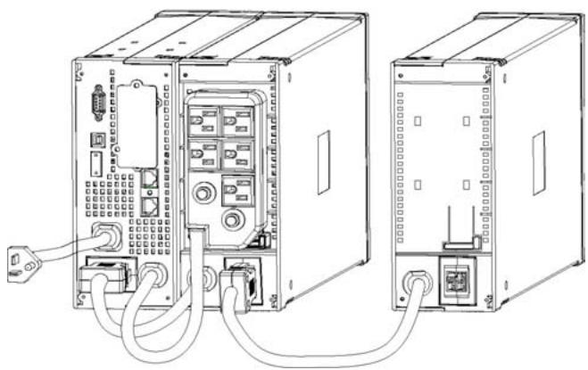
3000VA
There is one external battery port for the UPS itself:
- Connect the supplied battery module cable from the extended battery module to the external battery port on the back of the UPS.
- If continuing to add extended battery modules, repeat above steps.
9. BATTERY REPLACEMENT
The battery is the only UPS component which is not in permanent use. It has a product life of approximately 3 to 5 years. However, frequent major discharges or exposure to temperatures over 20^ will shorten its product life. We therefore recommend that users recharge the battery once every 3 months when the unit is not in use in order to compensate for natural discharging. UPS backup functioning time will depend on the load powered by the batteries, as well as their age and condition.
WARNING!
Batteries should always be replaced by qualified technicians. Batteries have a very high short circuit current: connection errors could cause electric arcs resulting in serious burns.
When the Bad Battery BAD BAT. indicator flashes and there is a continuous sounding, the battery may need to be replaced. Please check the battery connection or contact your local dealer to order a new battery.
CAUTION: To avoid running the risk of an electrical shock from high short circuit current, the following precautions should be observed before replacing the batteries.
- Turn off the UPS and disconnect the utility power cord from the wall outlet.
- Remove rings, watches, and other metal objects.
- If the battery replacement kit is damaged in anyway or shows signs of leakage, contact your dealer immediately.
- Properly recycle or dispose of used battery. Do not dispose of batteries in a fire. The batteries may explode.
Note: If you are not qualified to replace the battery, do not attempt to open the battery door. Please call local dealer or distributor immediately.
Recycle the used battery:
- Never dispose the batteries in a fire. It may explode.
- Do not open or damage the batteries. Released electrolyte is harmful to the skin and eyes. It may be toxic. You may also run the risk of an electrical shock from the high short circuit current.
Please do not discard the UPS, battery pack, or batteries into the trash can. To correctly recycle the used battery, please adhere to your local laws and regulations; you may contact your local recycling waste center for further information to properly dispose of the used UPS, battery pack and/or batteries.
750/1000VA
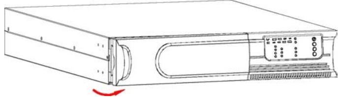
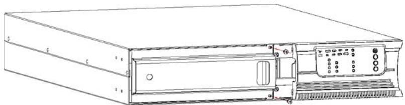
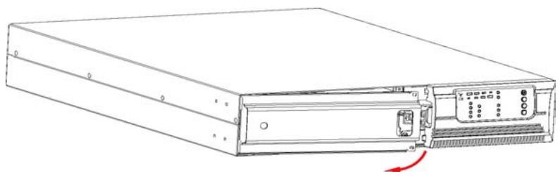
- Unscrew the front panel at both ends and remove it.
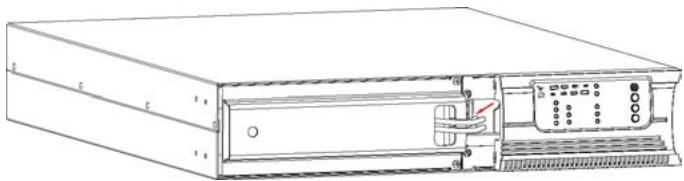
- Disconnect the battery cable from the UPS and remove the battery retaining bracket.
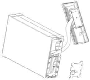
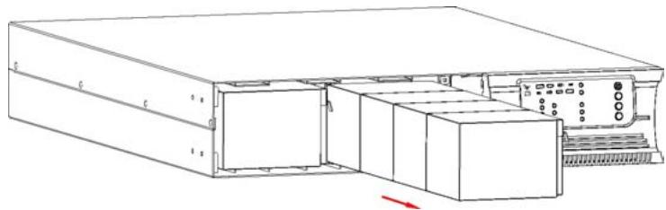
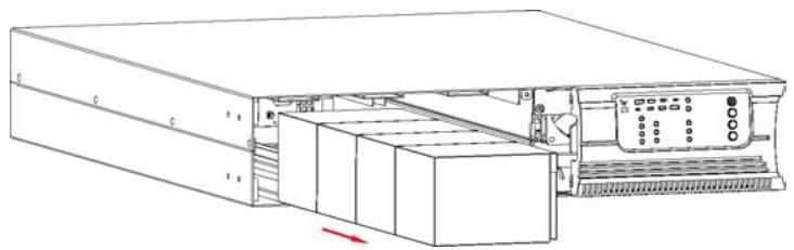
- Grasp the battery and pull it out from the front panel.
- Slide the new battery into the UPS
- Reconnect the battery cable and fasten the battery retaining bracket.
-
Close and reinstall the front panel.
-
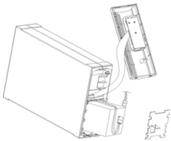
Remove the battery case front panel by pulling on both ends.
- Disconnect the battery cable from the battery pack.
- Unscrew and remove the battery retaining bracket.
- Pull the battery out onto a flat surface.
- Slide the new battery into the battery pack.
- Reconnect the battery cable and fasten the battery retaining bracket.
- Put the front panel back on the battery pack.
3000VA
- Remove the battery case front panel by pulling on both ends.
- Disconnect the battery cable from the UPS.
- Unscrew the battery bracket from the battery case
- Remove the battery bracket from the battery case by pulling on both ends.
- Pull the battery out (on the right side) onto a flat surface.
- Pull the left side of battery out onto a flat surface.
- Slide the new batteries into the battery case.
- Reconnect the battery cable and screw up the battery bracket.
- Put the front panel back on the battery case.
10. COMMUNICATION PORT
- RS232 + Dry contact (750/1000/1500/2000/3000VA):
DB9 Female (RS232 +dry contact)
| PIN # | Description | I/O | Function Explanation |
| 1 | DCD | Output | Low Battery Output (*normally open) |
| 2 | RxD | Output | RxD |
| 3 | TxD | Input | TxD |
| 4 | DTR | Input | (tied to pin 6) |
| 5 | Common | -- | Common (tied to chassis). For pin 1 & 8. |
| 6 | DSR | Output | (tied to pin 4) |
| 7 | RTS | Input | No connection |
| 8 | CTS | Output | AC Fail Output (*normally open,). |
2. RS232 + Dry contact (750/1000/1500/2000/3000VA):
The USB and RS232 are unable to operate at the same time.
11. TROUBLE SHOOTING
Should the UPS fail to function correctly we recommend you perform the following tests before calling the Hot Line.
Check list:
Is the main switch in the "ON" position?
- Is the UPS plugged into the mains power supply?
- Does the power supply fall within specified unit values?
- Has the fuse gone in the mains plug?
Is the UPS overloaded?
Is the battery flat or defective?
Audible Alarm Trouble Shooting:
| Problem | Cause | Solution |
| Sounding every 4 seconds | The UPS is on the battery | Check the input voltage |
| Sounding every second | The battery is running low | Save your work and turn off your equipment |
| Sounding continuously | UPS failure | Please contact your local dealer |
| Sounding every second | Output overload | Check load level indicator and remove some load |
| Sounding continuously | Battery may need to charge or service | Replace the battery |
General Trouble Shooting:
| Problem | Cause | Solution |
| The UPS does not come on when power switch is pressed | The power cord is not connected correctly | Check the power cord connection |
| The wall outlet may be faulty | Please contact your local qualified electrician | |
| The UPS output may short-circuit or overload | 1. Disconnect all loads and ensure nothing is lodged in output receptacles2. Ensure loads are not detective or shorted internally | |
| Internal fuse may be blown | Please contact your local dealer | |
| UPS does not provide power to the load | Power is available on one output receptacle | Check the output fuse |
| No output from any output receptacle | 1. Check the connected cable2. Ensure the load does not exceed the maximum UPS rating | |
| Battery has reduced backup time | Battery is not chargedBattery may no longer hold a full charge due to its age. | Re-charge the battery for at least 24 hours1. Recharge the battery for at least 8 hours2. Replace Battery |
| The UPS fault LED comes on | The UPS fails | Save your work and turn off the equipment. Please contact your local dealer |
| Connected equipment's lose power while connected to the UPS | The UPS may be over-loaded | Check the load status |
| The UPS may have failed | Please contact your local dealer | |
| The UPS is beeping continuously | The UPS is in fault mode | Check the audible alarms condition table |
| The button does not work | 1. The UPS is in energy saving mode2. The button is broken | 1. Wait for a while and try again2. Please contact your local dealer |
- TECHNICAL SPECIFICATIONS
| E3750 | E31000 | E31500 | E32000 | E33000 | ||
| TECHNOLOGY | Technology | On Line Performance High Frequency High Density | ||||
| Power | 750 VA | 1000 VA | 1500 VA | 2000 VA | 3000 VA | |
| Output form | Pure sine wave | |||||
| Protection | Overload, short-circuit, over-heat & overvoltage + tel/fax/modem line | |||||
| Power Factor | 0.7 | |||||
| PHYSICAL CHARACTERISTICS OF THE UPS | Dimensions 1 x P x h (mm) | 235 x 383 x 86.2 | 217 x 413.5 x 86.5 | 438 x 582 x 86.2 | ||
| UPS weight kg* this model carries its own batteries | 8.6* | 9.6* | 6.5 | 31.5* | ||
| Output connectors IEC model (220 V) | 4 outlets with backup time + protected RJ11/45 | 6 outlets with backup time + protected RJ11/45 | 8 outlets + one 16A outlet with backup time + protected RJ11/45 | |||
| Output connectors NEMA model (110 V) | 6 outlets with backup time + protected RJ11/45 | 5 outlets with backup time + protected RJ11/45 | 6 outlets + one 24A outlet with backup time + protected RJ11/45 | |||
| BATTERY CHARACTERISTICS FOR THE MAIN UPS | Battery type | 12V/7Ah | 12V/9Ah | - | 12V/5Ah | |
| Battery number | 2 | 8 | ||||
| Backup time (at full load) | 5 mins minimum (with battery pack for 1500 and 2000 models) | |||||
| Recharge time | 4 hours at 90% after complete discharge | 3 hours at 90% after complete discharge | ||||
| PHYSICAL CHARACTERISTICS OF THE EXTERNAL BATTERY PACKS | Dimensions 1 x P x h (mm) | - | 217 x 413.5 x 86.5 | 438 x 582 x 86.2 | ||
| Battery pack weight kg | 12 | 40.3 | ||||
| Battery type | 12V/7Ah | 12V/9Ah | 12V/5Ah | |||
| Battery number | 4 | 16 | ||||
| INPUT CHARACTERISTICS | Voltage | [110 - 120 - 127 VAC] or [220 - 230 - 240 VAC] | ||||
| Acceptable voltage range | [0-160 VAC] or [0-300 VAC] | |||||
| Line Low transfer (wide mode) | [77/84/89VAC ± 4%] or [154/161/168VAC ± 4%] | |||||
| Line Low transfer | [88/96/102VAC ± 4%] or [176/184/192VAC ± 4%] | |||||
| Line Low comeback | [93/101/107VAC ± 4%] or [186/194/202VAC ± 4%] | |||||
| Line High transfer | [132/144/152VAC ± 4%] or [264/276/288VAC ± 4%] | |||||
| Line High comeback | [127/139/147VAC ± 4%] or [254/266/278VAC ± 4%] | |||||
| Normal mode frequency | [50] / [60] Hz ±5Hz | |||||
| Generator frequency | >40Hz | |||||
| Surge rating (Joules) | [320] or [230] | [430] or [250] | [500] or [640] | |||
| OUTPUT CHARACTERISTICS (battery mode) | Voltage | [110/120/127 VAC] or [220/230/240VAC] | ||
| Regulation | +/-5% RMS for the entire battery voltage range | |||
| Frequency | [50] or [60] Hz + / - 1 Hz | |||
| OVERLOAD RATING | Line mode | 110%-0%, +8%; shutdown after 3 mins.150%-0%, +10%; shutdown after 10 cycles. | ||
| Battery mode | 110% ± 6%; shutdown after 30 seconds.120% ± 6%; shutdown after 5 cycles. | |||
| INTERFACE | RS - 232 | compatible with Windows, Linux and Mac environments | ||
| Dry contacts | ✓ | ✓ | ✓ | |
| USB | ✓ | ✓ | ✓ | |
| SNMP | non available | optional | optional | |
| EPO | non available | ✓ | ✓ | |
| LIGHT INDICATORS | AC MODE | Line LED on | ||
| Backup Mode | Battery LED flashing every 4 seconds | |||
| Site Fault | Site fault LED lighting (for 120Vac models) | |||
| Load/Battery Level | 4-segment LED bar - 0 - 25%: 4th LED on;26% - 50%: 3rd and 4th LEDs on; 51%-75%: 2nd, 3rd, and 4th LEDs on76% - 100%: 4 LEDs in a row all lighting | |||
| UPS Fault | Fault LED lighting | |||
| Overload | Overload LED lighting | |||
| Low Battery | Battery LED flashing every second | |||
| AUDIBLE ALARM | Backup Mode | Sounding every 4seconds | ||
| Low Battery | Sounding every seconds | |||
| UPS Fault | Continuously Sounding | |||
| Overload | Sounding every second | |||
| Battery Replacement | Sounding every second | |||
| ENVIRONMENT | Ideal environment | 0-40°C, 0 to 90% relative humidity (non condensing) | ||
| Noise level | < 45 dB | |||
| NORMS | Security / Standard | CE | ||