B&W 801D - Speakers B&W - Free user manual and instructions
Find the device manual for free B&W 801D B&W in PDF.
User questions about B&W 801D B&W
0 question about this device. Answer the ones you know or ask your own.
Ask a new question about this device
Download the instructions for your Speakers in PDF format for free! Find your manual B&W 801D - B&W and take your electronic device back in hand. On this page are published all the documents necessary for the use of your device. B&W 801D by B&W.
USER MANUAL B&W 801D B&W
Ooyniecs xpnons.....52
περιορισενη
Eyyunon 60
Pycckn
PykoBoIDCTBO IO
3Kcnpnyatau..61
OrpaHnueHHa
rapaHTna. 68
Magyar
Title, first name, surname
Address
Town, postcode, country
e-mail address
Product details
Model
Serial number
Date of purchase
Dealer details
Dealer name
Address
Town, postcode, country
e-mail address
Dealer stamp
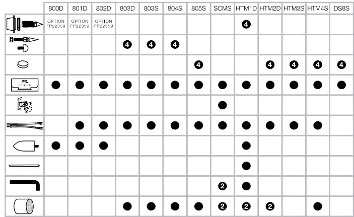
Figure 1
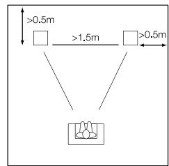
Figure 2
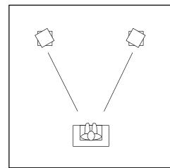
Figure 3
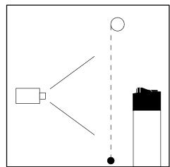
Figure 5
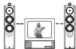
Figure 4
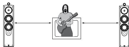
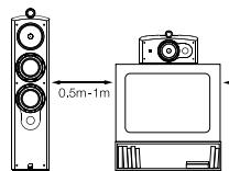
Figure 6
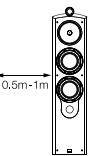
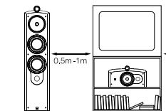
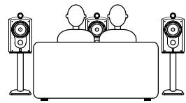
Figure 7
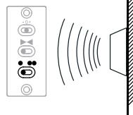
Figure 8
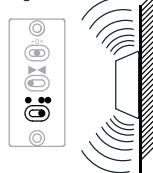
Figure 9
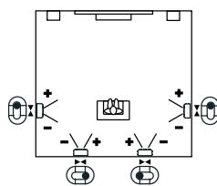
Figure 10
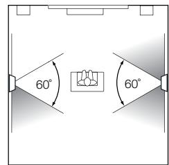
Figure 11
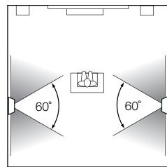
Figure 12
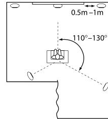
Figure 13
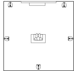
Figure 14
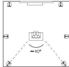
Figure 15
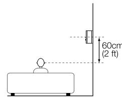
Figure 16
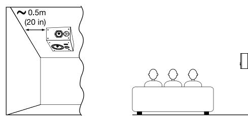
Figure 17
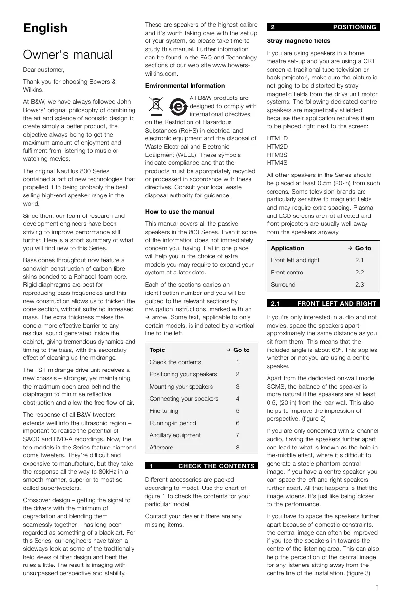
English
Owner's manual
Dear customer,
Thank you for choosing Bowers & Wilkins.
At B&W, we have always followed John Bowers' original philosophy of combining the art and science of acoustic design to create simply a better product, the objective always being to get the maximum amount of enjoyment and fulfilment from listening to music or watching movies.
The original Nautilus 800 Series contained a raft of new technologies that propelled it to being probably the best selling high-end speaker range in the world.
Since then, our team of research and development engineers have been striving to improve performance still further. Here is a short summary of what you will find new to this Series.
Bass cones throughout now feature a sandwich construction of carbon fibre skins bonded to a Rohacell foam core. Rigid diaphragms are best for reproducing bass frequencies and this new construction allows us to thicken the cone section, without suffering increased mass. The extra thickness makes the cone a more effective barrier to any residual sound generated inside the cabinet, giving tremendous dynamics and timing to the bass, with the secondary effect of cleaning up the midrange.
The FST midrange drive unit receives a new chassis - stronger, yet maintaining the maximum open area behind the diaphragm to minimise reflective obstruction and allow the free flow of air.
The response of all B&W tweeters extends well into the ultrasonic region - important to realise the potential of SACD and DVD-A recordings. Now, the top models in the Series feature diamond dome tweeters. They're difficult and expensive to manufacture, but they take the response all the way to 80kHz in a smooth manner, superior to most so-called supertweeters.
Crossover design - getting the signal to the drivers with the minimum of degradation and blending them seamlessly together - has long been regarded as something of a black art. For this Series, our engineers have taken a sideways look at some of the traditionally held views of filter design and bent the rules a little. The result is imaging with unsurpassed perspective and stability.
These are speakers of the highest calibre and it's worth taking care with the set up of your system, so please take time to study this manual. Further information can be found in the FAQ and Technology sections of our web site www.bowerswilkins.com.
Environmental Information


All B&W products are designed to comply with international directives
on the Restriction of Hazardous Substances (RoHS) in electrical and electronic equipment and the disposal of Waste Electrical and Electronic Equipment (WEEE). These symbols indicate compliance and that the products must be appropriately recycled or processed in accordance with these directives. Consult your local waste disposal authority for guidance.
How to use the manual
This manual covers all the passive speakers in the 800 Series. Even if some of the information does not immediately concern you, having it all in one place will help you in the choice of extra models you may require to expand your system at a later date.
Each of the sections carries an identification number and you will be guided to the relevant sections by navigation instructions. marked with an arrow. Some text, applicable to only certain models, is indicated by a vertical line to the left.
| Topic | → Go to |
| Check the contents | 1 |
| Positioning your speakers | 2 |
| Mounting your speakers | 3 |
| Connecting your speakers | 4 |
| Fine tuning | 5 |
| Running-in period | 6 |
| Ancillary equipment | 7 |
| Aftercare | 8 |
1 CHECK THE CONTENTS
Different accessories are packed according to model. Use the chart of figure 1 to check the contents for your particular model.
Contact your dealer if there are any missing items.
2
POSITIONING
Stray magnetic fields
If you are using speakers in a home theatre set-up and you are using a CRT screen (a traditional tube television or back projector), make sure the picture is not going to be distorted by stray magnetic fields from the drive unit motor systems. The following dedicated centre speakers are magnetically shielded because their application requires them to be placed right next to the screen:
HTM1D HTM2D HTM3S HTM4S
All other speakers in the Series should be placed at least 0.5m (20-in) from such screens. Some television brands are particularly sensitive to magnetic fields and may require extra spacing. Plasma and LCD screens are not affected and front projectors are usually well away from the speakers anyway.
Application Go to
Front left and right 2.1
Front centre 2.2
Surround 2.3
2.1 FRONT LEFT AND RIGHT
If you're only interested in audio and not movies, space the speakers apart approximately the same distance as you sit from them. This means that the included angle is about 60^ . This applies whether or not you are using a centre speaker.
Apart from the dedicated on-wall model SCMS, the balance of the speaker is more natural if the speakers are at least 0.5, (20-in) from the rear wall. This also helps to improve the impression of perspective. (figure 2)
If you are only concerned with 2-channel audio, having the speakers further apart can lead to what is known as the hole-in-the-middle effect, where it's difficult to generate a stable phantom central image. If you have a centre speaker, you can space the left and right speakers further apart. All that happens is that the image widens. It's just like being closer to the performance.
If you have to space the speakers further apart because of domestic constraints, the central image can often be improved if you toe the speakers in towards the centre of the listening area. This can also help the perception of the central image for any listeners sitting away from the centre line of the installation. (figure 3)
If you are also using the speakers for movies, you should try to match the audio image to the size of the screen. That generally means that the speakers should be closer together. A good starting point is to put the speakers about 0.5m (20-in) from the edges of the screen. (figure 4)
Bookshelf or on-wall speakers should be placed at a height that brings the tweeters approximately to ear level. In the vertical plane, the dispersion narrows in the crossover region between the midrange and tweeter drive units, when both units are working together. To preserve the optimum sound balance, try to keep within ± 5^ of this.
Floor-standing speakers have the angle of their optimum listening window adjusted for the height of the speakers and the typical range of ear height of seated listeners.
Go to section 3.
2.2
FRONT CENTRE
If you have an acoustically transparent screen, place the speaker behind the centre of the screen. Angle it towards the listeners if the tweeter is more than 5^ from ear height. (figure 5)
If you have a normal screen, place the speaker immediately above or below the screen, whichever is nearest ear height. Angle it towards the listeners if the tweeter is more than 5^ from ear height. A stand with tilt adjustment is available for the HTM2D, HTM2S and HTM4S. Consult your dealer for details. (figure 6)
If you are just listening to audio, place the speakers centrally and mount bookshelf or wall mount speakers with the tweeters at ear height. (figure 7)
Go to section 3.
2.3
SURROUND
Surround speakers generally fall into two main types - those that one might describe as 'normal' speakers - so-called monopoles, where the sound comes from a set of drive units mounted on the front of the enclosure - and those that give a more diffuse sound field, such as dipoles. Each type has its advantages.
Most multi-channel music is recorded with home entertainment in mind and is monitored using monopole surround speakers, whatever the multi-channel recording format. This enables better location of side and rear images, although the formation of such images is never quite as precise as it is between the front speakers.
Most films are originally balanced for cinemas, where a large number of speakers spread around the auditorium are used to create the surround sound field. In that case there are more surround speakers than there are discrete channels of information and a less precise image is created that gives an all-enveloping effect. Dipoles and similar diffuse speakers are better at recreating this type of sound field in the home, but using fewer speakers to do it. Image positioning with these types of speaker is never as precise as it can be with monopoles. However, they do have the advantage of making it easier to balance the system for a larger listening area.
You may well receive conflicting advice from different sources on the best type of surround speaker to use. The truth is that there is no one perfect solution for all situations and the final choice for any given application will be influenced by several criteria, some of which may have a degree of conflict.
DS8S only
Within the 800 series, the DS8S is the only speaker to offer dipole operation. In fact, this specialist surround speaker has the advantage of offering a choice of both monopole and dipole operation, either via a switch located on the front baffle, behind the removable grille, or remotely, using a 12V trigger from the surround processor. You may therefore choose whichever type of operation best suits the conditions of the listening room, the size of audience and the type of programme being played. Indeed, you may even change the characteristic for different types of programme and, as the total energy into the room is the same in both modes, no recalibration of the installation is necessary when switching between them.
In monopole mode, only the two drive units on the front face operate. In dipole mode, the front tweeter is disconnected; the side firing drivers are brought into operation and the crossover frequency to the bass unit is lowered. The drive units on opposing sides are connected out of phase with one another, which creates a wedge-shaped null zone, approximately 60^ wide, at right angles to the wall. If the listeners sit within this zone, they become less aware of the location of the speakers and hear more reflected sound; hence the diffuse nature of the sound field.
Use the bottom switch on the front baffle when selecting between monopole and dipole modes. In the
- position, the speaker defaults to monopole. (figure 8)
However, if a 12V signal is applied to the trigger input, internal relays switch to dipole mode. In the position, the speaker is always in dipole mode, whatever the trigger signal. (figure 9)
Set the direction of the positive and negative dipole lobes using the centre toggle switch marked on the front baffle. The stem of the switch points in the direction of the positive lobe.
For the smoothest panning of sounds between all the speakers in the installation, side speakers for all applications and rear speakers for 6.1 and 7.1 applications should have the polarity of the lobes set according to figure 10.
Application Go to
5.1 channel surround 2.4
6.1 and 7.1 channel side 2.5
6.1 channel rear 2.6
7.1 channel rear 2.7
2.4 5.1 CHANNEL SURROUND
DS8S only
If you are using the DS8S in dipole mode only, place the speakers on the side walls approximately 60cm (2 ft) above ear height and in line with the centre of the listening area. (figure 11)
If you are using the DS8S and switching between dipole and monopole modes for different applications, place the speakers on the side walls approximately 60cm (2 ft) above ear height and slightly behind the centre of the listening area, keeping the listeners within the 60^ wide null zone. (figure 12)
All models except DS8S
Place the speakers approximately 120^ round from front centre. The shape of the room will dictate whether they are placed on a side or rear wall. (figure 13)
Go to section 2.8
2.5 6.1 AND 7.1 CHANNEL SIDE
Place the speakers to the side, in line with the centre of the listening area. (figures 14 & 15)
Go to section 2.8
2.6 6.1 CHANNEL REAR
The rear channel of 6.1 EX recordings may be reproduced by a single speaker placed directly behind the centre of the listening area. (figure 14)
Go to section 2.8
2.7
7.1 CHANNEL REAR
These recommendations may also be used for a 6.1 channel system using two speakers at the rear, wired in parallel to the same channel.
Place two speakers behind the listening area to make an angle of approximately 40^ to the centre of the listening area. (figure 15)
Continue to section 2.8
If you use the system for movies, place the speakers approximately 60cm (2 ft) above ear height. (figure 16)
This is also the preferred height for the dipole mode of the DS8S in all applications, although it may also be mounted on the ceiling. Try to keep it around 0.5m (20 in) from the side wall. (figure 17)
For all other models, if you are listening to audio only and there are only one or two listeners, mount bookshelf speakers with the tweeters approximately at ear height.
If there are more listeners, raise the speakers just above head height to avoid obstructing the sound to any listener. (figure 18)
Continue to section 3.
3
MOUNTING
| Model | → Go to |
| 800D/801D/802D | 3.1 |
| HTM1D | 3.2 |
| 803D/803S/804S | 3.4 |
| 805S/HTM2D/HTM3S/HTM4S | 3.5 |
| SCMS | 3.6 |
| DS8S | 3.7 |
3.1
800D/801D/802D
On delivery, the speakers are fitted with roller glides to aid movement. Because of the extreme weight of these speakers, the rollers can cause indentation of wooden and other vulnerable floor surfaces. You should therefore take steps to protect such surfaces by using an intermediate layer such as floor tiles or thick felt. The latter will allow you to glide the speakers over smooth surfaces if you push the cabinet low down.
Bass performance may be enhanced by using the optional adjustable feet. These are produced separately in a pack of 4 (800 Series Floor Spike Kit, part no.
FP22359). They have 40mm (1.6 in) of vertical adjustment, allowing a certain degree of tilt if desired, and are reversible, having a spike for carpets on one end and a clear rubber pad for vulnerable surfaces on the other.
To fit the optional feet, first lay the speaker down on its side (to avoid possible damage to terminals or drive unit diaphragms). (figure 19)
Due to the weight of the speaker, this should be done by at least two people. Remove rings and other jewellery to avoid scratching the surfaces and provide a soft surface such as a piece of carpet that the speaker can lie on. You may also like to wear non-slip gloves.
Do not be afraid to handle the speaker by lifting on the side of the spherical midrange 'head'. It is a little unnerving, because the head is flexibly mounted on the bass cabinet, but it does come to a stop and is strong enough to take the weight of the speaker.
Using the Torx key supplied with the kit, remove the 4 roller glides from the plinth of the speaker and replace them with the feet. (figure 20)
Adjust the feet as described in section 3.3.
Go to section 3.3.
3.2
HTM1D
Supplied with the speaker are 4 adjustable feet and screws for fitting them to the cabinet. They have 40mm (1.6 in) of vertical adjustment, allowing tilt up to 8^ if desired. This is useful, as the most common situation will be for the speaker to be mounted on the floor under a large screen.
The feet are reversible, having a spike for carpets on one end and a clear rubber pad for vulnerable surfaces on the other.
Fit the feet during the unpacking procedure when the underside of the cabinet is exposed. This allows the inner packing pieces to remain in place against the underside of the cabinet as protection whilst the speaker is rolled over into the upright position, and be easily removed afterwards.
First read section 3.3 to familiarise yourself with the design. If the speaker is to be tilted back, fit the front threaded bosses with the cones facing outwards (figure 21) and the rear ones with the cones facing inwards (figure 22). This is as illustrated on the separate sheet placed in the carton.
Screw in the feet with locking ring attached, with either the spikes or rubber tips outermost, according to the type of
floor surface. Leave the tips of the feet protruding beyond the inner packing pieces for clearance when the speaker is upright.
After rolling the cabinet onto its feet and lifting off the carton, remove the inner packing and adjust the feet as described in section 3.3
Continue to section 3.3.
3.3 ADJUSTING THE FEET
The threaded bosses that hold the feet have a large conical shape on one side of the flange. For maximum height, fit the bosses with the conical shape towards the floor. (figure 21) For minimum height, have them pointing into the speaker. (figure 22)
Screw in the feet close to where you think the final adjustment will be, with the spikes or the rubber ends outermost as appropriate to the floor surface. If you do not intend to tilt the speakers, orient the bosses with the cones inwards and leave just enough thread exposed to fit the locking rings. Fit, but do not tighten the locking rings.
Stand the speaker upright and adjust the feet using the metal bar provided to give the amount of tilt required and to take up any rocking. (figure 23)
Finally, tighten the locking ring against the boss, again using the metal bar. (figure 24)
Go to section 4.
3.4 803D/803S/804S
For best performance, screw the adjustable feet into the threaded inserts in the base of the speaker as appropriate - spikes for carpets or clear rubber for wooden and other vulnerable floors. (figure 25)
Lay the speaker down on its side (to avoid possible damage to terminals or drive unit diaphragms). Remove rings and other jewellery to avoid scratching the surfaces and provide a soft surface such as a piece of carpet that the speaker can lie on.
Screw the lock nuts fully onto the feet and the feet fully into the base. (figure 25)
Stand the speaker upright and adjust the feet to take up any rocking.
Finally, tighten the locking rings against the threaded inserts. (figure 26)
Go to section 4.
3.5 805S/HTM2D/HTM3S/HTM4S
These systems should be mounted on a firm shelf or stand that allows the sound to be properly directed to the listeners.
For the 805S, we recommend the use of the FS-N805 stand that supports the speaker at the correct listening height.
For the HTM2D, HTM3S and HTM4S, the FS-NHTM stand supports these centre speakers low down so that the top of the speaker is no higher than 60cm (2 ft) from the floor, commensurate with positioning them below a large screen. The stand allows the speaker to be tilted back by 0^ , 4^ or 8^ .
Follow the instructions supplied with the stand in each case.
When mounting the speakers on a bookshelf, stick the 4 self-adhesive rubber feet to the base of the speaker. (figure 27)
Go to section 4.
3.6
SCMS
The speaker is designed to be fixed to a wall and is supplied with a bracket that allows adjustment of both horizontal and vertical angles. (figure 29) The bracket should be fixed to the wall using screws in the range 5mm to 6mm diameter (No.10 to No.12). The screw length should be chosen to give a minimum of 25mm (1 in) engaged thread. (figure 28)
Hold the template provided against the wall in the desired position and use a spirit level to line it up properly. The outside dimensions of the template correspond to the rear of the cabinet. Note especially that the centre of the wall plate does not coincide with the centre line of the speaker.
Mark the fixing holes on the wall and drill and plug the wall.
Ensure that the screw length and wall plug security are sufficient to hold the weight of the speaker. When fixing to drywall construction, try to arrange for the screws to go into a stud. B&W can accept no liability for any failure of wall or ceiling fixings.
Screw the wall plate D to the wall and test the firmness.
Part screw two of the supplied machine screws into the upper two threaded inserts in the back of the cabinet.
Offer the speaker up to the speaker plate E, locating the two screw projecting from the back of the speaker into the slots at the top of the plate.
Fit the remaining two machine screws through the plate E into the lower
threaded inserts in the cabinet and tighten all four.
Set the vertical angle of the speaker by adjusting screw B.
Fully tighten screw A.
Adjust screws C so that the friction of the three vertical hinges allows you to adjust the bracket but hold it in place once set.
Connect the speakers as described in section 4 before continuing.
Set the required horizontal angle and push the speaker back to the wall, but leave a little clearance to avoid rattles.
Go to section 4.
3.7
DS8S
The speakers may be fixed to a wall or ceiling using screws in the range 5mm to 6mm diameter (No.10 to No.12).
On the back of the cabinet are three wall plates. The screw head should be inserted into the round part of the aperture and slid fully along one of the slots. The slots are sprung loaded to prevent the speaker being readily knocked out of position. The screw length should be chosen to give a minimum of 25mm (1 in) engaged thread. (figure 28)
Ensure, especially when fixing to drywall panels, that the screw length and wall plug security are sufficient to hold the weight of the speaker. B&W can accept no liability for any failure of wall or ceiling fixings.
Use the template provided to mark the screw positions. The outside dimensions of the template correspond to the rear of the cabinet.
Stick 4 of the clear self-adhesive rubber pads to the rear panel of each speaker, one close to each corner. These stop the speaker vibrating against the surface and help keep it in position. (figure 30)
Adjust the protrusion of the screws such that the rubber pads are a friction slide on the surface when the wall plates are hooked over the screw heads. (figure 31)
Always check and ensure that:
- All the screws slide right to the ends of the slots in the wall plates.
- Screw protrusion is adjusted so that the rubber pads provide enough friction to prevent the speakers sliding out of position.
Go to section 4.
4
CONNECTIONS
All connections should be made with the equipment switched off.
The terminals accept a variety of cable terminations to suit most applications - 4mm banana plugs, 6mm and 8mm (1/4 in and 5/16 in) spades, or bare wires up to 6mm (1/4 in) diameter.
Important safety notice
In certain countries, notably those in Europe, the use of 4mm banana plugs is considered a potential safety hazard, because they may be inserted into the holes of unshuttered mains supply sockets. In order to comply with European CENELEC safety regulations, the 4mm holes in the ends of the terminals are blocked by plastic pins. If you are using the products in any country where these conditions apply, you should ensure that any banana plugs cannot be used in an unsafe manner by children or other uninformed persons.
Ensure each positive terminal on the speaker (coloured red and marked +) is connected to the positive output terminal of the amplifier and negative (coloured black and marked -) to negative. Incorrect connection may result in impairment of frequency response, poor imaging and loss of bass.
Always screw the terminal caps down fully to prevent rattles.
Model Go to
DS8S 4.3
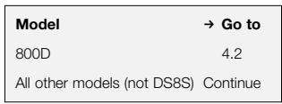
All other models Continue
All models in the range except for the DS8S may be bi-wired or bi-amplified. In 3-way systems, one set of terminals feeds the bass drivers and the other the midrange and tweeter. In 2-way systems, one set of terminals feeds the bass/ midrange driver and the other the tweeter.
Separation of the signal paths to each section of the speaker can improve imaging and the resolution of low-level detail, and allows the user to optimise the cable to the frequency range of use.
Bi-wiring involves the use of two separate 2-core cables from the same amplifier, one to each pair of terminals. This is the minimum we would recommend, but should you prefer to single wire, perhaps during the initial setup procedure or because you do not want to see a multitude of cables in the room, you must connect both positive and both negative speaker terminals together.
The ear is at its most sensitive in the midrange, so we recommend that, when single wiring, you connect the cable from the amplifier to the terminals that directly feed the midrange driver.
Bi-amplification goes a stage further and involves the use of two separate power amplifier channels for each speaker. It is not the same as having a fully active system, because the speaker's internal passive crossover is still used.
If using bi-amplification, ensure that each amplifier channel has the same gain, otherwise you will change the balance of the speaker. Check the absolute polarity. Some amplifiers invert the signal, and a mixture of different types may cause a dip in the overall response. If you have a mixture of inverting and non-inverting amplifiers, reverse the polarity of the connections from any inverting amplifier to the speaker.
Bear in mind that, even though midrange and, even more so, tweeter drivers can (and only need to) handle less continuous power than bass drivers, the amplifier feeding them needs to have an adequate voltage swing in order to supply the short-term high-frequency peaks in music without distortion. A high voltage capability implies high power, so it is not particularly desirable to have a lower powered amplifier feeding the midrange and tweeter than is used for bass drivers.
On delivery, the two pairs of terminals are electrically separate from one another ready for bi-wiring. (figure 32)
For single wiring, short cables are provided to link both positive and both negative terminals together. Each cable carries a spade connector at one end and a 4mm banana plug at the other.
When single wiring, connect the cable from the amplifier to the lower terminals on 2-way systems (805S, HTM4S, SCMS) and the upper terminals on 3-way systems.
On these terminals, use the opposite type of connector on the link cables to what you have terminating your main cable. For example, if your main cable terminates in spade connectors or bare wires, use the banana plug end of the link cables in the same terminals. (figure 33)
Go to section 5.
4.2
800D
On delivery, both positive and both negative terminals are connected together by link plates.
When single wiring, leave these links in position and connect the cable from the amplifier to the centremost pair of terminals. (figure 34)
When bi-wiring or bi-amplifying, remove the links after loosening the lower, larger diameter terminal caps. (figure 35)
The 4mm hole in the end of the terminal post features a collet that may be tightened around a banana plug using the upper, smaller diameter terminal cap.
Go to section 5.
4.3
DS8S
In addition to the normal speaker terminals, there is an additional pair of screw terminals to operate an internal 12V relay that switches the speaker between monopole and dipole modes from a remote trigger. (figure 36)
You cannot use this facility if:
a Your processor does not feature a 12V trigger at all.
b Your processor only offers a simple trigger that outputs a 12V signal when the unit is switched on. This can only be used to switch other equipment on and off at the same time.
Some of the most expensive processors allow you to assign a trigger to the type of programme being played. They recognise information on the disc that distinguishes between movies and multi-channel music. Others allow you to assign triggers to different inputs; so if, for example, you use a multi-channel SACD or DVD-A player for music and a separate DVD player for movies, you can set up a trigger accordingly.
The relay in the speaker needs a certain amount of current to operate, so check the specification of your processor first before proceeding. You will need to draw 45mA for each speaker you want to switch.
The relay in the speaker only works when the manual switch is set to the monopole () position. If there is no voltage to the trigger input, the speaker stays monopole. If a 12V DC signal is present, the relay overrides the manual monopole setting and switches the speaker to dipole mode. If you have the switch set to the dipole () position, the trigger feature will not work.
Continue to section 5.
5
FINETUNING
Before fine tuning, double check that all the connections in the installation are correct and secure.
Floor- and stand-mount speakers only
Moving the speakers further from the walls will reduce the general level of bass. Space behind the speakers also helps to create an impression of depth. Conversely, moving the speakers closer to the walls will increase the level of bass.
803D, 803S, 804S, 805S, HTM1D, HTM2D, HTM4S, SCMS only
These vented-box systems are supplied with foam plugs fitted in the ports. Normally, the speakers should be used with these plugs removed for maximum bass output, but if the bass is too heavy due to room effects and you cannot move the speakers further from the walls, refit the plugs to reduce the bass output. (figure 37)
If the bass is uneven with frequency, it is usually due to the excitation of resonance modes in the room
Even small changes in the position of the speakers or the listeners can have a profound effect on how these resonances affect the sound. Try positioning the speakers along a different wall. Even moving large pieces of furniture can have an effect.
For the most discerning listening, remove
bass and midrange grilles asdescribed in section 8 - Aftercare.

Tweeter diaphragms are very hard and easily damaged. The valves are held in place with a lid and any mishandling of the t into the tweeter may result in being attracted into the tweeter. For these reasons, we had that you leave tweeter grilles
delicate and easily damaged. The tweeter grilles are held in place with magnetism and any mishandling of the grille close to the tweezer may result in the grille being attracted into the tweezer diaphragm. For these reasons, we recommend that you leave tweeter grilles in place.
800D, 801D, 802D, HTM1D only
If you use these systems without the midrange grille, replace the plastic centre plug of the midrange drive unit with the solid aluminium plug in the accessory pack. Simply unscrew the fitted plug and screw in the replacement. Hand tighten only. (figure 38)
If the sound is too harsh, increase the amount of soft furnishing in the room (for example, use heavier curtains), or reduce it if the sound is dull and lifeless.
Test for flutter echoes by clapping your hands and listening for rapid repetitions. Reduce them by the use of irregular
shaped surfaces such as bookshelves and large pieces of furniture.
DS8S only
In monopole mode, the high-frequency output level may be adjusted using the top toggle switch on the front baffle. (figure 39)
In the centre 0 position, the system response is nominally flat. The ^+ position gives more output, which may be required, for example, if the acoustic of the room is dull, if circumstances dictate that the speakers have to be placed more off line than
recommended, or if the speaker is built into custom furniture and placed behind fabric that is more absorbent than that on the grilles supplied.
Conversely, the - position reduces the level for when the room acoustic is too bright or if you want to reduce your awareness of the speakers' location.
Experiment to find the mode settings best suited to your requirements. Typical combinations are:
- All surround speakers monopole.
- Side speakers dipole, rear speakers monopole.
- All surround speakers dipole.
It would be unusual, but not impossible, to set side speakers to monopole and rear speakers to dipole.
6
RUNNING IN
The performance of the speaker will change subtly during the initial listening period. If the speaker has been stored in a cold environment, the damping compounds and suspension materials will take some time to recover their correct mechanical properties. The drive unit suspensions will also loosen up during the first hours of use. The time taken for the speaker to achieve its intended performance will vary depending on previous storage conditions and how it is used. As a guide, allow up to a week for the temperature effects to stabilise and 15 hours of average use for the mechanical parts to attain their intended design characteristics.
However, longer run-in periods (as long as a month) have been reported and there is evidence to suggest that this has little to do with the speaker changing and more to do with the listener getting used to a new sound. It is especially so with highly revealing speakers such as these, where there may be a significant increase in the amount of detail portrayed compared to what the listener has previously been used to; the sound may
at first appear too "up front" and perhaps a little hard. After an extended period of time, the sound will seem to mellow, but without losing clarity and detail.
7 ANCILLARY EQUIPMENT
Speakers of this ability deserve signals of the highest quality. Choose your electronic equipment and interconnecting cables with care. We can give guidance on what to look for when choosing ancillary equipment, but cannot recommend specific items. The standards of such products are improving all the time and your dealer will be able to demonstrate a variety of suitable up-to-date products.
In the specification we recommend a range of amplifier powers. The higher figure is defined by the power handling capability of the speaker. When calculating the power handling, it is assumed that the amplifier is not run into clipping, which distorts the frequency power spectrum of the signal, and that the signal is normal programme material. Test tones from oscillators and the like are not applicable. The lower figure is the minimum we consider necessary to achieve reasonable listening levels without audible distortion in the smaller room (less than 60m^3 or 2000 cu ft). The higher the power you use, the less likely you are to experience amplifier clipping.
You can often tell how good an amplifier is at driving complex speaker loads by looking at its power rating into both 4 and 8 loads. The nearer the ratio is to 2:1 the better, as it indicates a good current capability.
In order to reduce the effect the cable has on the frequency response of the speaker to inaudible levels, the impedance of the cable at all frequencies (measuring both positive and negative conductors in series) should be kept as low as possible and certainly below 0.1 . At low frequencies, the DC resistance of the cable is the dominant factor and you should choose a gauge of wire sufficient to achieve the impedance requirements over the length of cable you need to use. At mid and high frequencies the inductive component of the impedance can dominate the DC resistance. This and other properties influenced by the detailed construction of the cable become important. Ask your dealer for advice on the best cable for
8
AFTERCARE
Veneered cabinet surfaces usually only require dusting. If you wish to use an aerosol cleaner, remove grilles first by gripping round the edges and gently pulling them away from the cabinet. Spray onto the cleaning cloth, not directly onto the product. Test a small area first, as some cleaning products may damage some of the surfaces. Avoid products that are abrasive, or contain acid, alkali or anti-bacterial agents. Do not use cleaning agents on the drive units. The grille fabric may be cleaned with a normal clothes brush whilst the grille is detached from the cabinet.
When replacing grilles, ensure that the pegs are correctly aligned with the receptacles in the cabinet before pushing into place.
We have chosen the finest wood veneers for the surface of the cabinet, but please be aware that, like all natural materials, the veneer will respond to its environment. Keep the product away from sources of direct heat such as radiators and warm air vents to avoid the risk of cracking. The wood is treated with an ultra-violet resistant lacquer to minimise changes in colour over time, but a degree of change is to be expected. This effect may be particularly noticeable where the area covered by the grille, or areas kept in shadow, change more slowly than other areas. Colour differences may be rectified by exposing all the veneer surfaces equally and evenly to sunlight until the colour is uniform. This process can take several days or even weeks, but may be accelerated by careful use of an ultra-violet lamp.
800D, 801D, 802D, HTM1D only
To replace the midrange grille, locate the central peg in the hole at the tip of the plastic centre plug fitted to the drive unit. Push the centre of the grille firmly, but do not force a misaligned peg as damage may result. The outer rim of the grille is held in place by spring tension in the spokes of the grille fret.
The painted surfaces of midrange heads and tweeter housings will benefit from the use of antistatic cleaner.
Avoid touching the drive unit diaphragms, especially the tweeter, as damage may result.
Due to the delicate nature of tweeteter domes, we strongly recommend that you do not attempt to remove twitter grilles.
Limited Warranty
This product has been designed and manufactured to the highest quality standards. However, if something does go wrong with this product, B&W Group Ltd. and its national distributors warrant free of charge labour (exclusion may apply) and replacement parts in any country served by an official B&W distributor.
This limited warranty is valid for a period of five years from the date of purchase or two years for electronics including amplified loudspeakers.
Terms and Conditions
1 The warranty is limited to the repair of the equipment. Neither transportation, nor any other costs, nor any risk for removal, transportation and installation of products is covered by this warranty.
2 This warranty is only valid for the original owner. It is not transferable.
3 This warranty will not be applicable in cases other than defects in materials and/or workmanship at the time of purchase and will not be applicable:
a for damages caused by incorrect installation, connection or packing,
b for damages caused by any use other than correct use described in the user manual, negligence, modifications, or use of parts that are not made or authorised by B&W,
c for damages caused by faulty or unsuitable ancillary equipment,
d for damages caused by accidents, lightning, water, fire heat, war, public disturbances or any other cause beyond the reasonable control of B&W and its appointed distributors,
e for products whose serial number has been altered, deleted, removed or made illegible,
f if repairs or modifications have been executed by an unauthorised person.
4 This guarantee complements any national/regional law obligations of dealers or national distributors and does not affect your statutory rights as a customer.
How to claim repairs under warranty
Should service be required, please follow the following procedure:
1 If the equipment is being used in the country of purchase, you should contact the B&W authorised dealer from whom the equipment was purchased.
2 If the equipment is being used outside the country of purchase, you should contact the B&W national distributor in the country of residence who will advise where the equipment can be serviced. You can call B&W in the UK or visit our web site to get the contact details of your local distributor.
To validate any claim under the warranty, you will need to produce the original sales invoice or other proof of ownership and date of purchase.
Français
Mode d'emploi
Cher Client,
3.5 805S/HTM2D/HTM3S/HTM4S
805S/HTM2D/HTM3S/HTM4S 3.5
SCMS 3.6
DS8S 3.7
3.1 800D/801D/802D
3.5 805S/HTM2D/HTM3S/HTM4S
Estas cajas acústicas incorporan de series ruedas para fácilar su desplazamente. Como consecuccion del elevado peso de estas cajas, las ruedas peuvent provocar MARLAS MARLAS MARLAS MARLAS MARLAS MARLAS MARLAS MARLAS MARLAS MARLAS MARLAS MARLAS MARLAS MARLAS MARLAS MARLAS MARLAS MARLAS MARLAS MARLAS MARLAS MARLAS MARLAS MARLAS MARLAS MARLAS MARLAS MARLAS MARLAS MARLAS MARLAS MARLAS MARLAS MARLAS MARLAS MARLAS MARLAS MARLAS MARLAS MARLAS MARLAS MARLAS MARLAS MARLAS MARLAS MARLAS MARLAS MARLAS MARLAS MARLAS MARLS MARLAS MARLAS MARLAS MARLAS MARLAS MARLAS MARLAS MARLAS MARLAS MARLAS MARLAS MARLAS MARLAS MARLAS MARLAS MARLAS MARLAS MARLAS MARLAS MARLAS MARLAS MARLAS MARLAS MARLAS MARLAS MARLAS MARLAS MARLAS MARLAS MARLAS MARLAS MARLAS MARLAS MARLAS MARLAS MARLAS MARLAS MARLAS MARLAS MARLAS MARLAS MARLAS MARLAS MARLAS MARLAS MARLAS MARLAS MARLAS MARLAS MARLAS MARLAS MARLAS MARLAS MARLAS MARLAS MARLAS MARLAS MARLAS MARLAS MARLAS MARLAS MARLAS MARLAS MARLAS MARLAS MARLAS MARLAS MARLAS MARLAS MARLAS MARLAS MARLAS MARLAS MARLAS MARLAS MARLAS MARLAS MARLAS MARLAS MARLAS MARLAS MARLAS MARLASMARLLARMARLLARMARLLARMARLLARMARLLARMARLLARMARLLARMARLLARMARLLARMARLLARMARLLARMARLLARMARLLARMARLLARMARLLARMARLLARMARLLARMARLLARMARLLARMARLLARMARLLARMARLLARMARLLARMARLLARMARLLARMARLLARMARLLARMARLLARMARLLARMARLLARMARLLARMARLLARMARLLARMARLLAR
mismas.
3.5 805S/HTM2D/HTM3S/HTM4S
3.5 805S/HTM2D/HTM3S/HTM4S
Estas colunas devem ser colocadas numa prateleira firme ou suporte que permita que o som sera correctamente dirigido para os ouvintes.
3.5 805S/HTM2D/HTM3S/HTM4S
3.5 805S/HTM2D/HTM3S/HTM4S
3 ANAPTHsH TON HXEiON
| Movélo | →Παράγραφος |
| 800D/801D/802D | 3.1 |
| HTM1D | 3.2 |
| 803D/803S/804S | 3.4 |
| 805S/HTM2D/HTM3S/HTM4S | 3.5 |
| SCMS | 3.6 |
| DS8S | 3.7 |
3.1 800D/801D/802D
AnoTo epyootao, ta nxia
deltaouv troxouc kuiianqnsou
bonoovn tmezakivnontouc.Aoyo
tou meyalou bipouc tow nxeiw,oi
tpoxoi autoi mopei va npokalaeeouv
Znuae aeulivec n aalecs uaiotheTc
enpuaveic. n pnootatepsiete
teloiue iboudc enpuaveic evai
kaloVa xnpaioonoe t eva
evdoaeo otrpuja metaeu troxowv
kai natwatoC otav etakivite Ta
nxie (tn.x.Eva letto xali n eva
diabp0o ano toox).Haetakivnon
townv xeiow yivetai uekola
onpwovtocn tv kumiva xanla.
H ano0oanTwv maoawv 8a 8eAiwOeiaoTavxpaouonnoTeTa (npoapetika)pu6uOicEva nAmuata, ta onia papeovtai Exwpiota o oukeuaia twv 4 Teauiow (800 Series Floor Spike Kit, part. no. FP22359). Mnpouov va puBmuotov ou uoc xepi kai 40 mm ka aoc erpnenov av xpeiaZeiav dwoTe ia upkn kian sto nxieo Akoun exuvdu Onuapeveic, miu akiace yia tonoeton enaw v oxai, kui ma e laatixevia neLmuata yeuaiotec enipaveic(£luo,napapoK.ln.).
Ia va tonotheoae ta nelaata, Eanawote ta xieia oto naai (kai oxi me Tnv emnpooia oyn h tvn iow nleupa npoc ta enavw, ia va anopuyete Tnv npoknon zniuc otouc akpoedktec twk aalwiw n ota neyapawa-Eikova 19).
Aoyoutobapouc taw nxiow, n diaokaiauuthnpereva yivei ano toulaixotovduo atota.桑naowte ta nxeia enaov oe eva xai kai av opate daxtuia id aalaa koajnata, byaTe ta yia va mny yapeTe nvyipaeia touk. KaO 0 na tav eniocv opate kai eioika avtoiaohtikayvanta.
Mny biotaete va kpatnoete to nxeio ano tv opauikn "kepaan" tou meyaapwov eaoaiw. Iomega cac pavei kan wuaiaon thoy wu Eukamiac tnc, etai onw civai
toTOnTeNtJeuV oTnV KApNiva, aAlambda apKeTa avTeKtIK ia va avTeEi to bApoc Tou nXeiou.
3.5 805S/HTM2D/HTM3S/HTM4S
Ta nχεia tutanotobetouvtaiα βaánn páqi,étoi wote o nxcov z φανει ωοτα touac kροatec.
Ia to 805S, ouviotoue va
xpanoioantoe t n baof FS-N805
nou fepvei to xneio sto katalnnlo
uoc.
Tt a Kevtipka nxEia HTM2D, HTM3S
Kai HTM4S, n Baon FS-NHTM eivai n
nEov katalan yiata ta tonoTei
apKeTxAumla (n enavnAeupa
touc dEv EENepva ta 60 cm ano tv
enipaveia tou natwatoC), Etai
Wotte v mnpouv va mouuv aveta
kAtw ano tnOovn.
mnpoeite va dwoeTe niow kliion otN
baon, 0^ 4^ n 8^ moipov.
Akoouothe Tc o8nyie c nou ouvodouv tn bao.
AV tonoetae ta nxiia ae kaioio paoi, kooane otny katw naEuupa touc ta 4 autokolnta aotixevia neMaata (Ekova 27).
Ybaxaemblnokynatelb,
Bnaorodapm Bac 3a npno6peTeHne akyCTHueCckn CNTcEM (AC) npOn3BODCTBA kOMPAnH Bowers & Wilkins.
B&W cTporo cneyet fHnococfnn
Jxoha Bayarpca, CHTaBwero, YTO
pa3ap60ka kAcYCTuHecKnx CNTEM
RbNIETCQcHTAHmE NcKcCTBa
Haykn, C cIeBIO DOCTaBnTB BlaadenbUy
AC hAmBoNBbuee yDobONbCTBe OT
npocnyuINBAHNMy3bIKn n pOcMoTPO
fKnIM
B opinhaIbHOI cepm Nautilus 800
PpIMeHHeMAcca HObIX TEXHOrOri,
PpoDBNHyBuxx3Tu cepnIO B YncIO
cAmbIX npOdaBaembIX IHeek high-end AC B Mpe.
C Tex nop haun Hxhepebl yuehble pa6oTajn nad daJIbHeNIMM COBepweHCTBoBaHNm EyaHNOH KOHcTpyKUn. Bot KpATKn pepeHb HOBOBBeDEHn dIra 3Toi cepIN.
IinΦy3Opb6acOBKOB Tenebp
npEcdTAHOTc60B C3HDbUH N3 DByX
CIOEB YrNEBOJOKHA, MEXy KOtporBMn
HaxoDITcNe HONoNCTnOPOR RohaceL.
IINBocPOn3BEdENHn H3KNx CaTc0T
HyKeH KAK MOxHO 6oEe JcETkN
DInΦy3Op, n HOBaB cTpyKTpya
No3BOJIeY TBEnuHTb ToLmHHy
DInΦy3OpA, He NObIbua 3HaChTeNbHO
ero MaCCbI. TOnctbl DInΦy3Op
RAJRETC 6OJe 3ΦeKTHBbIM
6apBepor DMsTcatoHybIX
napa3nTHbix 3YbKO, BO3NHKaIoUxh
BHTPN KOpNyca, npndaet bacy
NOTpraCaOHU dyHnAmNKU y O6nlaaet
BTOPnuHbM 3ΦeKToOM "OunSeHHa"
CpeDNHb YacOTc.
CpeHneHuacToTHbI DnHAmNK FST
NoNyUHIN HOByIO KOp3Hy -6Ooee
npOHyIO,HO No-PrpExMeHY
MAKcHMaJIbHO OtKpblTyIO, Cbo6oDo
ponyLcAoUioY Bo3dUnHbN toTOK BO
n36exAHne OTPaxhen 3Byka.
Yactotnbl danaa30n TBNTepoB B&W npocntnpaetcdaNekoB 6bnaTb yIbTa3ByKa, YTO BaxHo Dnpealna3au nolHOro noTeHuaSACD nDVD-A 3anCe. Tenebp kynonblhe dHfpyObo BCHdAmNKOB fpaarMaHCKHX moDenei cepin 6dyT mEmt bJMa3HOe HAnbJeHMe. 3To cNOxHHN I DORoR pOeCC, HO B erO pe3yIbTaTe rnaKdA qACToTHa xapakertpcntka npodLeBaETcdo 80kU, 4TO npebbuaaet Bo3MOXhoCTn
MHORIX TaKa3b1BaEmaBxI CynePTBtIEPOB.
PaarabokKa KpocccOBepoB, YBa 3aadaa
-IOCTABNTCINHANK DINHAMIKAM C
MHNIMAbHOI DEpaDAUChE N "CSnTB" BOEDINO XN 38YUAnHe, -DIOIRO
CUHTaIACb YEm-TO BPODe YErpHOI
MarNI. Co3dABA 3Ty cepInO, HauNI
INKeHepbIO NDBePrrn AnAHIN3Y
HEKOTOPIE TPAIDIOUNHBe B3rNDbI Ha
NoctpoEHne FInbTPOB nCerKa
06oOnl npArbIA. 3ByKOBoi o6pa3
npIObpEN HepeBSoJedHnyo
NEpcNEKTHBY INcStbNBOCTb.
O6naad akyctuuecknmi CNTeMaMNI Bbocchwero kNcca, cneJeT no3ab0ntb8c 6 ix npabInbHOn 3KcNpyataun. IooTOMy 13uyTe BHIMATEIbHO daHHOe pykoBDCTBO. Eue boIbe IHFOpaMauNi Bbl HainTeB bpaDetax FAQ n Technology hawero Be6-canwax www.bowers-wilkins.com.
HnfoPMaunno 3aunTe Okpykaoue cpebl


BCE npoDyKtBu B&W CO3aHbI B PONHOM COOTBE7CBM C
Mekdyapodmbm DnpekTBAMN o
OrpanuHcHemm nCnOlb3OBAHn
OnachbixMatepnAnoB (Restriction of
Hazardous Substances - RoHS) B
3NeKtpnueckom n 3NeKtpOHOM
obpydoABHH, a takaee no er0
yTnIa3aun (Waste Electrical and
Electronic Equipment - WEEE). 3NaK
nepepepkHytoro Mycophoro baka
3NaHaayet COoBeTCTBe NpeKtNBAM I
TO, yTo npDyKT DoJxen6 bbl
IpaBnblbOy Tynl3OBAH nnll
nepepabotan. PpokohcybTnpuyTeCb C
Baawei MechtNo orpAhnzaue,
KOTOPa 3aHmMaTeC yTynl3aunei
OTXoDB, No BOpncam npAbnbHOB
Cdaa Nbaero OboOpdyOBAHy BYNlb.
Kak noJIb3OBAtbcra pyKOBOdCTBOM
3To pykoBODCTBO OTHOCNTcKo BCEM AC cepri 800.BepaTHO,CaCTb coepkaxuXcB HEM daHbIx He kacaetc HENocpeDCTBeHNBOaNXAC, HO oblaDaHne 3TMM daHbIMN NOMOXET bblOpTa DOnONHmTeJIbHbIe MoDen, KOTOpBE MOrYT Notp6obatcbn dpaRacWpeHnBAwe cnCTEmb By 6yUeM.
Kakdbpa3dienpykoBODCTbAmeet
mENTMnKauNHOHbMOHEpC.CTpeNka cnoceLyOUMHOMepOM
npedraaTe BAmpeRtIN K
yKa3aHOMy pa3dely.TekT,
OTOHcuiTTOIbKO ONpeDeJIeHHbIM
MoJELAM, NOMEueHBePTNKaJIbHOJ
JInHei cneBa.
MarHHTbIe noJIra paccEHHa
EcNAC BxOJaT B CoCTab DomaHrero
KHHOTeATPA, OCHOBAHORo Ha
BnDEOyCtPOiCTBe C3NeKtPOHNO
HyueBb Tpy6kO (06bHNOM HIN
IpoEkuHNOHM TeBEN3Ope),
y6eINTeCb, YTO nOJI paCCeHnI
MaHHTbIX CNCTEM INHAMMKOB He
BHOcT NcKaXeHn B IN3ObpaXeHne.
CnEuaHImuPBOBaHbYe AC
UeHTpAlbHorO KAHaA ImeIoT
MaHHTHOE 3KpaHnPOBaHne, PONKbKy
HXn3aHuHHe Tpe6yEt pa3MeUeHn B
HeNoPeCDtBEHNo Bn3OcTn OT
EkPbAA:
HTM1D
HTM2D
HTM3S
HTM4S
OctaHbIe AC cepinn DoJNkhbl
pa3MeuattcbMHNmYMM B 0,5 M O3JT
TeneBn3OpOB. HeKoTPObe Mapkn
TeleBn3OpOB oO60o YCbTBNTeBbIK
MaHTHOMy NIOU MOrYT
notpe6oBaTb BoJbWeero pacCTOnHHa
Ha INa3MeHbIe N KK NaHei
MaHTHoe None He BnIReT, a
ΦpOtaHbIe IpoeKToPbI obSyHNo n
TaK paCnoOnXeHbI Ha 3NaChTEnbHom
pacCTOnHHOT AC.
PpIMHeHne AC Pa3dEe
Фонтальны леваяnpавая 2.1
ΦoHTaIbHa YeItpaIbHa 2.2
2.8 BBJCOTA AC OKPYX.3BYKA
Ecnn Bbl nconb3ye tncTeMy dna npocMToa pfHbMo, nomeCTne AC npimepno Ha 60 cm Bbl ue yobhr yuei. (pncyohk 16)
3TO tAKHe npEIOHOHTENbHn BA BICOTa Ds8S,paOtaoueB DINOJbHOM pEKHMU,npBCexPpIMEHNEHX. XOT3Ty AC MOKHO CMOTNPOBaTb Ha NotOnKe. CtapAIECb, Tc06bl OHa oCTOnla OT 60kOB ToCtebl He MeHee, cHm H a 0,5 M.(PcYHOK17)
YTO KACAETCR octaIbHbIX MOeJI, TO eCNI Bbl cnyuapeTe TOnbKO My3bKy, npUeM cnyuataRei He 6ObnSe DByx, CMOHTpyIte NonoUhIe AC Tak, YTO6bi TBnTEpBi bbln pInmepHO Ha Bbcote yueH.
Ecnn Cnyuataeneon 60bnue, noDnHmnte AC yTb BBye OyOBH naOBoBt, YTO6bl 3ByK 6ecPiPeNTCTBeHHo DoCTaran kKaJdOrO CNYaTeJe. (pCvHOK 18)
3.5 805S/HTM2D/HTM3S/HTM4S
3TN AC donJHKbI MOHTInpoBaTbc Ha yctOuHINBOI PONKE HNI CTOnKe TAK, UTO6bl 3yBk bbl HapPabEn Ha cnSuWateNen.
Длг 805S pekomeHnyem CTонуКу FS-N805,poДеркимваоую AC ha Heo6xodmОm Дьnpoclyшаньн BiLcOTe.
Длгцentральнх AC HTM2D,HTM3S и HTM4S cyucesctByet CTOnKa FS-NHTM. Берх сmoTHnpoBaHNoHa эТоу CTОКЕ NOКONKH PACNOnaRaTeC He BbIe 60 CM OT Na, NOtOMy МоЖно NOCTaBtBE noJd 6OBJIbIM Зраham. CTОКЯ NOБONJIe нakLoHniTB AC Ha3ad Na 0^ 4^ Иln 8^
PnMOHTaxe CneyTe HNCTpyKUHM, PnJIararaembIM K CTOnkAM.
Ecnn AC 6yyt cTba Ha noIke, npKpEnIte K dHy kKaXdoi AC no 4 camoknuepece peHIOBbIe HOKKn. (pncyHOK 27)
HOPMATHBOB 6e3oNaCHOCTN CENELEC, 4-MM OTBepctn Ha TOUPKX KJEMM 3aKpblTb
nlaactMaccoBbIM BCtBaKAMc. Ecnn Bbl npoxmbaete B pernohe, rde DeCTByOT yka3aHhble HOpMaTINbbl 6e3OanacHOtN, NCKLIQUHTe BO3MOXHOCTb ONACHORo NCNOIb3OBaHnI WteKePOB "6aHaH" DeTBMn HecBeDuymn B3poclbIM.
Y6eHntecb, YTO noIOnOxNtBnHa
KEMMa AC (KpaCHOrO 2eTa,
nOmeEHnHa 3aKaOM " +") coEiHHeNA C
noONoXtBnHO BbIXoHDo KNeMMo
yCUNTeBA, a OTPuTcAteBnHa KNEMMa
AC (UePHorO 2eBaT, nOmeEHnHa
3aKaOM "-)- c OTPuTcAteBnHO
BbIXoHDo KEMMOy ycInNTeJr.
HnepaBnJIbHoe NOcEOHNHeHne MOxET
pNBBeCTN K UxydUeHNu YaCToTHoN
XapakTepeCTNUK, HeKaueCTBeHHoN
aKyCTNuCecko BV3aylNi3aun Nnotepe
BcTeJa tuaTeJIbHO 3aTfIbMaIE TOROKBN KEMM BO I36EkaHHe UyMa
MoeJIb
→Pa3dien
DS8S
4.3
OctaIbHbIe MoJeIe
PpOdoJkaIte
Bce moJIeJI cepIN, KpOme DS8S,
IOnyCKAOT POKILOUHEnIE C
mONJb3oBAnHM dByx Ka6beJIe
(6n-BaepnHI) nJb dYbcNtTeJIe (6mAMnIHr). Y 3-nOIOChbIX AC oHa rpynnna
KNeMM pNtAE7 bocOBHKu, a Dpyra- Cc
m B4 DNHAMKKu. Y 2-nOIOChbIX AC OHa
rpynnk Na KneMM pNtAE7 C/H4 DNHAMNK,
Dpyra- TBNTep.
Pa3deneHne nyte cnHana do KaJdoi Cekzim AC moxet ynuuWntb KaueCTBO 3ykoBOrO o6pa3a n pa3peWHeNc TnxHX dTeTae, a TaKke daET Bo3MOxHOCt bbl6paTb ONTMnAlhBi KAbel DJI KAkDOn dNaana3OHa cactoT.
Bn-BaepnH npednonaraet
noCooendHeMe KAKdoi napbl kEmm
AC KOhOMy n Tomy Xe yCunHtieno
OTDeMbIM 2-KJInbHBM Ka6bEm.3To
peKoMeHdyEmb HAMM MNHMym.Ecnn
BBy Cze Xe hCnOpN3yeTe
OndokabEnbHOe noCooEdnHeHne,
HannpimE, B npoucece
NePBOHaueAhBoH NactpoRiKn iNn iN3-3a
HeKeJaanBa BVdTeB b KOMHaTE MHOro
IpoBoDob, O63aTeBnHO CoeHNHte
kEmMb AC nonapHo: noLoXHTenbHyO
cNoLoXHTenBHO, OTRpaTeBHyO c
OTpUaTeBnHO.
Helenobueeckoe yxo Hanboonee
YbCTBntEnbHO K cpeDnHM YacToTAM,
N03TOmy npn OndokabenbHom
coEINHeHHM Mbl peKoMeHdyem 3aBeCTn
Ka6bET OycnHtEna H rpynnk
KnEMM, nIITaOuSy C h dInhamkp.
Bn-AmNHF-3TO cneDyUoHn shar, npednonaraoiu nniTHeK KdoAC OT dByx OTdEbnbHX KaHAnOB ycHNTeIa. B OTNHyEOT NOnHOCTbO AKTNBOH CNTcEMbl, pnp TakONkOHypaunCBe-TAKn MCNoB3yeTcB BHTpEnHHN NacBNNHKn KPCCOBEP AC.
PImMeHRA 6n-AMnIHr, y6eIInTeCb, YTO BCE KAHAbIy cYNInTeR NHEOT OndHakOBbKo3OΦuIeNt EYcINHeHRA, HNaue ToHaBbHb5 BaAnC AC 6yDet HapUeHN. PIOBepbTe a6coIOnTHyIO nONARHOCTb. HeKoTOpBie ycINTeINn HEBPnpyOT CnHAp, NoTOMy IcNoJIb3ObaHNye cYNInTeEN pAaJIbXbTIINOBMOKET Bb3BaTb npoBAN b CyMMaHPoH XapAKTepNCtKe. EcNn Bb paonnonaraTe HneBEPnpyUoiMIM HEnHBePtnPyIOUIMm ycINInTeLAMM, IN3MeHNTe NOJAPHOCTb NDcOeDNIHeHRA BCEx HNEpTrpyIOUxNycINInTeEN K
KOJIOHKaM Ha 06paTHyI.
IMeTe B VdU, YTO, XOTa CUY
oc6eHNo B4 dHnAMnKIn MOryT
HyJdaTbCBAmHSei DnITeBHO
noDabDMIO MOuHcNTo, CEM BaCOBNK;
ycnITeNBx INIHTaOHU, DoNXeH
mETb p3aMMax BByXoNDHO HaprJxEHIN,
DOCTaTOHbI NnIpepeaOn KpATKNX
BbICOOKACToTHbIX My3bIKaJIbHBx NIKOB
63 nCKaxehNI. BbICOKOE Jx
hnapRzHeHne NOpa3ZymEaET BbICOKYIO
MOuHcOtB, PO3OMY HeKeLaTEbNO
PiNTaB CY nBv DnHAMnKt O yCnITeN
MeHbSei MouHcNTo, CEM BaCOBNK.
Modenb
→Pa3dien
800D
4.2
7 O DPyrNX KOMNOHEHTAX
Akyctnueckne cntEmb taKoro Klacca 3acnykBAOT CnHnla BblCooaIwero KaueCTBa.TuaTeNbHO bBbipaTe 3NeKtPOHNOE o6OpDBOAHne I coEDHNHTBHe lyKa6eNl dna CBOeI ayNDOCHTEMb.MbMOxEM nocOBEToABt Bam,HaTOcNe dyET o6paatb BHMaHne pRn Bb6ope npOxN KOMOnEOHTOB,HO He B COsTOrHHn peKOMeHDoBATb KaKeIe N6OpReJeHnhYe H3DeNIA. O6OpDobAHne TaKoro pOda NoctoHHo 6HOBnIeTcN yUyHuAeTcN,DInpe Nomoket Bam bB6pTaBoHoeMne HAmboeeNoXoJHOaMne H3DeNIA.
B TeXHcECKx xapaKTepeNCTkax
yKa3bIaBaTc peKOMHeYMaEM
MOUChOCTb ycINITeR. BepXnHra
rPAnHauOp npedeLHeTc npedeLBo
DOynCTUMo MOUChOCTb aKcYtueckCkO
cnCTeMbI. Ppi paCHTe npedeLHO
DOynCTUMo MOUChTc
npedlonaraetc, YTO yCuINlTeB
pa60TaET 63"OTceKn, KOTopar
nCKaXaET cNEKTPaIbHoe
pacnPdeJeHHe 3Heptm CnHArA, n
yTO CnIHAR RANETC HOPMaJIbHOJ
MBykAlbHo NpORpAMMo. CnHaNbl
NCbItaTeLbHbIX rHeApTOpOB IN IM
NOdo6HBe B daHHom cnYcaH e
npIMeHmMbI. HnKHaR pTaHCA
yKa3bIaBET Yu MINImAbHbIYIO
MOUHOCTb, KOTOPa, NO HaSeMy
MHEHInO, He6bXODIMA DnI TORO, YTO6bI
MH Be6bIbSi OKMhATE (Mehee 60 M)
aKcYtueckSs CnCTeKCTCb 3BuYaA C
npiMeHMo I rPOMKCTbO 63e
CblIMbIX NcKaXeHNI. HEm Bblse
MOUChOCTb ycINITeR, TEm MeHbIe
BepoTHoc7, YTO OH BOINDET B pEXIM "OTcKKn".
3aayactyMOKHO OueHnTb
cnooc6hoctb ycnnteH cnpaBnTbC KOMPLeKCHoH arpy3kO no er0 BbXIOHO MOChOStn Ha rpy3ke 4 Ω n8Ω. B nDeane 3tn Dba noka3aTeIa DOxNhbOTOHc2cKaK 2:1- cEM 6bnHexe 3TO OTHOseHne K 2, TEm BBHe Harpy3OuHa cnooc6hocTb no ToKy.
ДяТоуTO6bI BnHnHe Ka6eHa aAMNITUYHO-aCTOTHYIO xapaKTePncTky akyCTIeCKO CTNEMbOcTABALoCb HIXe npOra CbIuMmOcTb,IMNeDAHC Ka6eHa H BCEx YacToTax (pNi H3MepeHIn O6a NpoBODnKa Ka6eCoDAHEnb IocNeDobATeBbHO) OJOnKe 6bIb Ka MOKHo 60JIe Hm3KM,ero MAkCMaJIbHO DoNyCTHMoe 3aueHene - 0,1Ω. Ha H3KHX YAcToTAX DOMHNpyUoiMMФakTopOM OKa3bIaETcA kAtBnHOE conPotOBnEHne, NO3OTMy cLdEyET BbIbpaTb Ka6eB c NpoBODnKOM TAKOH ToIunHbI, KOTOPa OBScNEuT pI npEMnEMoe cOpOTBnEHne npI Tpe6BuMeO DInHe Ka6eHn Ha cpeHnx N bICOKHX QACTOTax INHyKTNBHOe cOpOTBnEHne OKa3bIaBcTc BIIwe AKTHBOr. COOTBEcTBeHHo, 3to cOpOTBnEHne I HeKOTOpBle dpyHne CBovCTBa Ka6eN, ONpEJIenMeBc Oco6BehnOCTaMn erO KOHcTpKuIN, pIWO6PeTaIoT BOJIwSe 3aueHne. IocOBetyTeCb c DInepom O bblOpe Ka6eHa, Hau6Boe nOxdoJaero dR BaWix yCNoBv.
8
yXoD
O6bHNo yXoJd 3aKnIOuAeTcB CtIpaHnn bIbn c NOBepXHOCTN KOpnyCa. Ecnbl XoITNe
INONlb30BaT bYcTaeee a3pO30JIbHOe cpeCTBO, Chaayala CNMITE
DEKOPATINbIe peWTeKN, OCTOpOXHo
NOTAHyB h Ce6B. PaCnblnIte
a3pO30JIb HcAnfETK, a He npRMO Ha KOpNc AC. JnA hauana npOBepTe
DeIECTBue YcTaeero cpeCTBa HAMOn YUacTK, T.K. HEKOtOpBie
cpeCTBa MOrTy NopEeNTb
NobEPxHOCTb. I36eraIe abPa3INbHbIX, KNCLOTNbIX, UeONuHbIX NIM
ANTb6akTepnaIbHbIX BeueCTB. He NCNb3yTE uHCTuaNE cpeCTBa dInDnHAMIKOB. TKaHb OTCoeDNHEHbIX OT
KOpNyca pEeTOk MOHXuCHTNb
O6bHNo OJedXHO uTeKoN.
Bo3paaHpeWTeKNHaMeTO, y6eIDTeCb, 70I WnIIbKnpeWTeKN HaxoDTc TOUHO HAnPOTNB He3d, I NIIbN NOTOM HAXIMAIte Ha HIX.
ДлгOTdelenKn KOpnyCoB Mbl BbIbpaHn LnyuHne cOpta shoHa HATypalbHoro DepeBa, Ondako CneJeT NOMHtB, YTO KaK n IIO60B npnoDHH MaTePnA, OHN pOBeRKeHb Bo3DeiCTBINO OKpykaIoUeI cpebl. Jepxnte
KOLOHNI NOdaIbIe OTE NCTOCHIKOB
TENJI, TAKINK KApaIaNATOpBI,
TENIOBEHTNUITOpBI INN 6aTaapei
ZETHPaIbHOrO OTONJIeHNI, YTObOI
1366eaTbPacTepeCKBaHnI. DepeBO
NOKpIbTO JAcOM, CTOnKIMK K
yIbTPaDNIOLETOBOMY IN3JUeHNIO, DnI
MNHNMaIZAUIN MImEHNEH NcBeTa COBEmH, Ondako KaKoe-To
BbUBeTahME BCE paBNO BO3MOxHO. 3To
OCoEHO HzAMeTHO BTex MeCTax, Ie
Iak 6blc KcbPT IOd rPnlEM, INI Jxe B
TEHNI, IN3MHeH CBOB TcEBt 60one
MeDJIeHNO, Yem B DpyInx MeCTax.
PaHnla B Okpacke MoXET 6blTb
3aIaNKeHa BVICTaBLeHNHEm BCex
FaHepoBAHHbX NobepxHOCTNa
CoJHue Do TEX NOP, NOKA OHa CTAHeT
He3AmEtHO. 3TOT npOceC MoXET
3aHbTb HEckOJIbKO DHeN IINI HeDeJIb,
HOero MOXNo YcOUPINbYMeJIbIM
aKKyPAthMI INCNOL3BOAHmE
yIbTPaDNIOLETOBIO lambl.
Tolbko dlya 800D, 801D, 802D, HTM1D
YTo6bI npKpeNtB peeTky CU
DnAMnKA, BCTABTe CEHTPAbHyO
wnlbKy B OTBepCTne Ha KOHZe
nnactIKOBOro KOnpAkaHa DNAMKa.
PiToHO pNxMMte CEHTppeWetKn.
He nbTaIeTcB CTABaTb HETOHO
OpHEINPOBaHHy IOHNbKy C
pNMeHENHEM CNbl, TaK KAK 3TO
MOket pNBeCTN K NOBpeJDeHnM.
KpaarpeEeTKUdEpxBaIoTcHa
MeCe THaTKeHmEE cnII.
OkpaenheHbke KOpCyBa CnB Hb DnHAMNKOB XOpOwYcHCTNt b aHTNCatNaueckOn cAnfetKoI.
Избогатейnpикховеник Дифузорам, особени К дифузору ТВпета, tak кег лгчecьсero норapedы.
13-3a XPYKIOCTNIIMDyO3pa 7BTRpeA Mbl CTPORe POKOMHeYMe HnIbTaTbCBA CHRTb HeNDEKOPATNBHyO peWETKY.
OrpaHnueHHaI rapaHTn
DahHoe 3dEJIne 6bIIO pa3pa60taHO n npOu3BSeEDo B COOTBECTBm C bIcOuyaMHm CTAndaptAm KauCtBa. Ondako, pN o6hApjXeHHn KaKoi-Ni6o HeNCpAbaHOctn, KomNaHn B&W Group Ltd. n eHaOnohNbHbe
DnCTPn6bIyTOpbl rapaHTnpyIOT 6eCnPaTHbI peMOHT (CyueCTByIOT HEKOTOpBle IcCKIoUeHHn) n 3aMeHy cAteT B LiIObO CTpaHe, 06cLyXkBAeMoH OPhiuaNbHbIM DnCTPn6bIyTOpOM KOMNaHn B&W
Даннанorраннаннан rapantnien deiCTbnteNbHa n NapnoI od OndHOro rOda co Dn npIOpeTeHNn 3MdENn
KOHeYhbIM NOTpe6bTeJIeM.
YcnoBna rapaHTnn
1 DaaHaa rapaHTnra orpaHnUbaeTcnoynHKo o6OpyDobAHna.3atpTaIbno nepeBO3Ke nIObIe npTyne3aTpaTbI, a TAKKe pNCK pNOTKIOUChEN, nepeBO3Ke INHCTaJIIpOBAHm IN3dEnJIne NOKpbBaIOrCa DaHHo rapaHTnei.
2 DieCTBNE daHHo rapaHTn paNPOCTpAHReTc TOnbKO Ha nepBOHauNaHOrO BnaJeNbca. fapANTMy He MoKet 6bTbpePeHaHa Dpyromy mIcy.
3Данная rapатуг
pacnoctpaHreTc TOnbkoHa Te
HncnpaBHOCTN, KOTOpIe Bb3BaHbI
deFeKTHbIMMaTePnAnamn N/nn
deFeKTamnpnIpnO3BOdCTBe Ha
MOMENT npNo6pTeHn Hne
pacnoctpaHreTc:
a. Na NOBPEKJDeHNA, Bb3BaBHHe HnpePABnIbHOHCTaJIaNeH, NPOCoEOHNHEHEM NmYtaKOBKO,
6. Na NOBpeJXeHnI, Bbl3BaHHbIe
NcIOJIb3OBOAHMe, He
COOTBECTBYUOIM ONICAHOMY B
pyKoBOdCTBe No pIIMHeHmIO, a
TaKJe HEnpAINbHbIM ObaPeHnEM,
MOdIaMHNPOBAHMe IInI
NCIOJIb3OBAHnE 3aIaNChbIX qAcTeI,
He npO3BEdHbIX IInIe
Odo6peHHbIX KOMPAnHe B&W,
B. Na NOBEXJDEHNA, BB3BaHNbHe HENcnpaBHBm IINI HENOpXODaUMC BCNOMORATeJIbHMbIM O6OyDObaHMe,
I. Ha NOBpeJXHn, Bbl3BaHhIe HecuactThbIMn CUYaAMn, MoJIHnei, BOIOI, NOKAPOM, BOHOI, Ny6bHbIMn 6eCnpOJaKMn INIe JIObIMn DpyrIMn PakTopAmn, He NODnaAoiUcMn NOD KOHTpObn KOMPAnHm B&W e oOpMaIbHbIX dIcTPrN6bIoTOpOB,
Д. Издени, сешильный Homep KOTopbix Блл Имсэну, УнчToxKeH INI Csehan HeY3HabAeBMiM,
e. Ha M3dEJIa, POnHKnA aIIN MoDInΦKAnaIaN KOTOpbIX PnOIN3BODINcIb IaMOp, He yONIOHOMOeHHbIM KOMNaHneB W&W.
4 DaaHaa rapaHTnraBJIeTcN
dONJHHeNHem K NaHIOHaJIbHbIM/
peHIOHaJIbHbIM 3aKoHOJaTeBCTBaM, KOToPbIM NOJINHArTOc DIIeIpeB I INs
NaHIOHaJIbHbIE DnCTpN6bIoTObT, To
ecTb pRn BO3HNKHOBeHHNI
npOTIBOpeChy, NaHIOHaJIbHbIE/
peHIOHaJIbHbIE 3aKoHOJaTeBCTBa
IMeOT npIOPiTETHyO CIny. DaHnaHra
rapaHTn He HapuJaet Bawix npab
noTpe6nteJ.
Kya o6paTnTBc3ra rapaHTmHbIM 06cIyKmbAHnEM
PnI Heo6xoDAMOCtNPOyENHae rapaHTnHOrO o6cLyXBaHN, BYbONHtne cIe dyUOuSe 8aM:
1 Ecnn obopyoBaHne nCnoNb3yeTcB Ctpane npio6peTeHHa, Bam Heo6xOdimo CBra3atcB c yonlHOMOeHNbIM dInlePom KOMnAHIN B&W, yKOTOpORo 6blNo npio6peTeHO obopyoBaHne.
2 Ecnn obopyobanHe nCnoIb3yeTcra 3a npedenamn cTpaHbnpno6pTeHNB, Bam Heo6xOdImBOB83atcBc NaHOnHObHBmDnCTpn6bIyTOporom KOMPAnHH B&W DaHH C TpaHe, KOToPBmNOCOBETyETB, Rte MOxHOPOHNtB o6pyoDaBH.Bo MoXeTne N03BOHNtB bKOMPAnHH B&W BeNIKO6pHTAHNNiXneNocetntb NaH Be6caIT, YTO6bY3HaTb KONTAKTHA anpe BaWero MeCTHOrO nCtPr6bIyTOpa.
3.5 805S/HTM2D/HTM3S/HTM4S
2.2KANAL PRZEDNI CENTRALNY
3.5 805S/HTM2D/HTM3S/HTM4S
3.5 805S/HTM2D/HTM3S/HTM4S
Tyto reprosoustavy je nejlepe montovat na firemn drzaky ci stojany. Zajstite tim jejich optimni uchyceni i smerovani.
Pro 805S doporu&ujeme pouziti stojanu FS-N805.
Procentry HTM2D,HTM3S a HTM4S umozhne stojan FS-NHTM podepreni tak,aby vrsek reprosumstavy nebl vyse nez 60 cm nad podlahou,coz stale umozhne jeho umisteni pod zobrazovač. Stojan také umozhne sklopit zadni Častroduktoru o 0^ 4^ ci 8^
mistle dlky pnut zeber mrizy.
Environmental Information


Alfa B&W:sprodukter ar uftformade for att folja de internationella direktiven
3.5 805S/HTM2D/HTM3S/HTM4S
3.5 805S/HTM2D/HTM3S/HTM4S
3.5 805S/HTM2D/HTM3S/HTM4S
EU DECLARATION OF CONFORMITY
We,
B&W Group Ltd.
whose registered office is situated at
Dale Road, Worthing, West Sussex, BN11 2BH, United Kingdom
declare under our sole responsibility that the products:
800D, 801D, 802D, 803D, 803S, 804S, 805S, HTM1D, HTM2D, HTM3S, HTM4S, DS8S, SCMS
comply with the EU Electro-Magnetic Compatibility (EMC) Directive 89/336/EEC, in pursuance of which the following standards have been applied:
EN 61000-6-1 : 2001
EN 61000-6-3 : 2001
EN 55020:2002
EN 55013:2001
and comply with the EU General Product Safety 2001/95/EC, in pursuance of which the following standard has been applied:
EN 60065:2002
This declaration attests that the manufacturing process quality control and product documentation accord with the need to assure continued compliance.
The attention of the user is drawn to any special measures regarding the use of this equipment that may be detailed in the owner's manual.
Signed:

G Edwards
Executive Vice President, Operations
B&W Group Ltd.
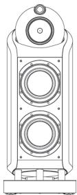
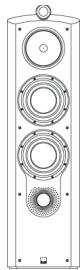
800D
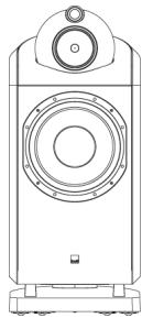
801D
| Technical features | Free-mounted diamond dome tweeter |
| Kevlar® brand fibre cone FST™ midrange | |
| Rohacell® cone bass | |
| Nautilus™ head | |
| Matrix™ cabinet | |
| Flowport™ |
| Free-mounted diamond dome tweeter |
| Keclar® brand fibre cone FST™ midrange |
| Rohacell® cone bass |
| Nautilus™ head |
| Matrix™ cabinet |
| Flowport™ |
Description 3-way vented-box system
3-way vented-box system
| Drive units | 1xø25mm (1 in) diamond dome high-frequency |
| 1xø150mm (6 in) woven Kevlar® cone FST™ midrange | |
| 2xø250mm (10 in) Rohacell® cone bass |
| 1xø25mm (1 in) diamond dome high-frequency |
| 1xø150mm (6 in) woven Kevlar® cone FST™ midrange |
| 1xø380mm (15 in) Rohacell® cone bass |
Frequency range -6dB at 25Hz and 33kHz
-6dB at 23Hz and 33kHz
Frequency response 32Hz - 28kHz ±3dB on reference axis
32Hz - 28kHz ±3dB on reference axis
| Dispersion | Within 2dB of reference response |
| Horizontal: over 60° arc | |
| Vertical: over 10° arc |
| Within 2dB of reference response | |
| Horizontal: | over 60° arc |
| Vertical: | over 10° arc |
Sensitivity 90dB spl (2.83V, 1m)
90dBspl (2.83V, 1m)
| Harmonic distortion | 2nd and 3rd harmonics (90dB, 1m) |
| <1% 45Hz - 100kHz | |
| <0.5% 80Hz - 100kHz |
| 2nd and 3rd harmonics (90dB, 1m) |
| <1% 40Hz - 100kHz |
| <0.5% 50Hz - 100kHz |
Nominal impedance 8Ω (minimum 3.1Ω)
| 8Ω (minimum 3.5Ω) |
| 350Hz, 4kHz |
Crossover frequency 350Hz, 4kHz
50W - 1000W into 8 on unclipped programme
Recommended 50W - 1000W into 8 on unclipped programme amplifier power
0.1Ω
Max. recommended 0.1Ω cable impedance
| Dimensions | Height: 1180mm (46.5 in) (not including feet) |
| Width: 450mm (17.7 in) | |
| Depth: 645mm (25.4 in) |
| Height: 1192mm (46.9 in) (not including feet) |
| Width: 506mm (19.9 in) |
| Depth: 682mm (26.9 in) |
Net Weight 125kg (275 lb)
118kg (260 lb)
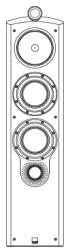
802D
Free-mounted diamond dome tweete
Kevlar® brand fibre cone FST™ midrange
Rohacell cone bass
Nautilus™ head
Matrix ^TM cabinet
FlowportTM
3-way vented-box system
1x 025mm (1 in) diamond dome high-frequency
1x 150mm (6 in) woven Kevlar cone FST" midrange
2x 200mm (8 in) Rohacell cone bass
-6dB at 27Hz and 33kHz
34Hz - 28kHz ±3dB on reference axis
Within 2dB of reference response
Horizontal: over 60^ arc
Vertical: over 10^ arc
90dBspl (2.83V, 1m)
2nd and 3rd harmonics (90dB, 1m)
<1% 40Hz - 100kHz
<0.5% 70Hz -100kHz
8Ω (minimum 3.5Ω)
350Hz, 4kHz
50W - 500W into 8 on unclipped programme
0.1Ω
Height: 1135mm (44.7in) (not including feet)
Width: 368mm (14.5in)
Depth: 563mm (22.2in)
80kg (176 lb)
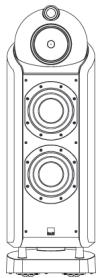
803D
Free-mounted diamond dome tweeter
Kevlar® brand fibre cone FST™ midrange
Rohacell cone bass
Matrixcabinet
Flowport
3-way vented-box system
1x 025mm (1 in) diamond dome high-frequency
1x 0150mm (6 in) woven Kevlar cone FST™ midrange
3x 180mm (7 in) Rohacell cone bass
-6dB at 28Hz and 33kHz
35Hz - 28kHz ±3dB on reference axis
Within 2dB of reference response
Horizontal: over 60^ arc
Vertical: over 10^ arc
90dBspl (2.83V, 1m)
2nd and 3rd harmonics (90dB, 1m)
<1% 50Hz - 100kHz
<0.5% 90Hz -100kHz
8Ω (minimum 3.0Ω)
350Hz, 4kHz
50W - 500W into 8 on unclipped programme
0.1Ω
Height: 1164mm (45.8 in) (not including feet)
Width: 306mm (12 in)
Depth: 457mm (18 in)
45kg (98 lb)
803S
Technical features Free-mounted aluminium dome tweeter
Kevlar® brand fibre cone FST™ midrange
Rohacell cone bass
Matrixcabinet
FlowportTM
Description 3-way vented-box system
Drive units 1 × 0.25 ~mm (1 in) aluminium dome high-frequency
1x 0150mm (6 in) woven Kevlar cone FST™ midrange
2x 180mm (7 in) Rohacell cone bass
Frequency range -6dB at 28Hz and 50kHz
Frequency response 35Hz - 22kHz ±3dB on reference axis
Dispersion Within 2dB of reference response
Horizontal: over 60^ arc
Vertical: over 10^ arc
Sensitivity 90dB spi (2.83V, 1m)
Harmonic distortion 2nd and 3rd harmonics (90dB, 1m)
<1% 70Hz - 22kHz
<0.5% 80Hz - 20kHz
Nominal impedance 8Ω (minimum 3.0Ω)
Crossover frequency 350Hz, 4kHz
Recommended 50W - 250W into 8 on unclipped programme amplifier power
Max. recommended 0.1Ω
cable impedance
Dimensions Height: 1063mm (41.9 in) (not including feet)
Width: 291mm (11.5 in)
Depth: 433mm (17 in)
Net Weight 41kg (90 lb)
804S
Free-mounted aluminium dome tweeter
Kevlar® brand fibre cone FST™ midrange
Rohacell cone bass
Matrixcabinet
Flowport
3-way vented-box system
1x 025mm (1 in) aluminium dome high-frequency
1x 0150mm (6 in) woven Kevlar cone FST™ midrange
2x 0165mm (6.5 in) Rohacell cone bass
-6dB at 30Hz and 50kHz
38Hz - 22kHz ±3dB on reference axis
Within 2dB of reference response
Horizontal: over 60^ arc
Vertical: over 10^ arc
90dB sp1 (2.83V, 1m)
2nd and 3rd harmonics (90dB, 1m)
<1% 90Hz - 22kHz
<0.5% 120Hz - 20kHz
8Ω (minimum 3.0Ω)
350Hz, 4kHz
50W - 200W into 8 on unclipped programme
0.1Ω
Height: 1020mm (40.2 in) (not including feet)
Width: 238mm (9.4 in)
Depth: 351mm (13.8 in)
28kg (62 lb)
805S
Free-mounted aluminium dome tweeter
Kevlar® brand fibre cone bass / midrange
MatrixTM cabinet
FlowportTM
2-way vented-box system
1x 25mm (1 in) aluminium dome high-frequency
1x 0165mm (6.5 in) woven Kevlar® cone bass / midrange
-6dB at 42Hz and 50kHz
49Hz - 22kHz ±3dB on reference axis
Within 2dB of reference response
Horizontal: over 60^ arc
Vertical: over 10^ arc
88dB spl (2.83V, 1m)
2nd and 3rd harmonics (90dB, 1m)
<1% 100Hz - 22kHz
<0.5% 150Hz - 20kHz
8Ω (minimum 3.7Ω)
4kHz
50W - 120W into 8 on unclipped programme
0.1Ω
Height: 418mm (16.5 in)
Width: 238mm (9.4 in)
Depth: 351mm (13.8 in)
11.5kg (26 lb)
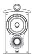
HTM1D
Technical features Free-mounted diamond dome tweeter
Kevlar® brand fibre cone FST™ midrange
Rohacell cone bass
Nautilus™ head
Matrixcabinet
FlowportTM
Magnetic shielding
Description 3-way vented-box system
Drive units 1xø25mm (1 in) diamond dome high-frequency
1x 0150mm (6 in) woven Kevlar cone FST™ midrange
3x 200mm (8 in) Rohacell cone bass
Frequency range -6dB at 32Hz and 33kHz
Frequency response 38Hz - 28kHz ±3dB on reference axis
Dispersion Within 2dB of reference response
Horizontal: over 60^ arc
Vertical: over 10^ arc
Sensitivity 90dB spl (2.83V, 1m)
Harmonic distortion 2nd and 3rd harmonics (90dB, 1m)
<1% 55Hz - 100kHz
<0.5% 100Hz - 100kHz
Nominal impedance 8 (minimum 3.7Ω)
Crossover frequency 350Hz, 4kHz
Recommended 50W - 500W into 8 on unclipped programme amplifier power
Max. recommended 0.1Ω
cable impedance
Dimensions Height: 585mm (23 in) (not including feet)
Width: 974mm (38.3 in)
Depth: 580mm (22.8 in)
Net Weight 93kg (205 lb)
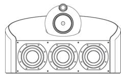
HTM2D
Free-mounted diamond dome tweeter
Kevlar® brand fibre cone FST™ midrange
Rohacell cone bass
Matrixcabinet
FlowportTM
Magnetic shielding
3-way vented-box system
1x 025mm (1 in) diamond dome high-frequency
1x 0150mm (6 in) woven Kevlar cone FST™ midrange
2x 0180mm (7 in) Rohacell cone bass
-6dB at 35Hz and 33kHz
41Hz - 28kHz ±3dB on reference axis
Within 2dB of reference response
Horizontal: over 60^ arc
Vertical: over 10^ arc
90dB spl (2.83V, 1m)
2nd and 3rd harmonics (90dB, 1m)
<1% 80Hz - 100kHz
<0.5% 100Hz - 100kHz
8Ω (minimum 3.1Ω)
350Hz, 4kHz
50W - 300W into 8 on unclipped programme
0.1Ω
Height: 329mm (13 in)
Width: 841mm (33.1 in)
Depth: 387mm (15.2 in)
31kg (68 lb)
HTM3S
Free-mounted aluminium dome tweeter
Kevlar® brand fibre cone FST™ midrange
Rohacell cone bass
Matrixcabinet
Magnetic shielding
3-way closed-box system
1x 025mm (1 in) aluminium dome high-frequency
1x 0150mm (6 in) woven Kevlar cone FST™ midrange
2x 0165mm (6.5 in) Rohacell cone bass
-6dB at 35Hz and 50kHz
42Hz - 22kHz ±3dB on reference axis
Within 2dB of reference response
Horizontal: over 60^ arc
Vertical: over 10^ arc
90dBspl (2.83V,1m)
2nd and 3rd harmonics (90dB, 1m)
<1% 100Hz - 22kH
<0.5% 120Hz - 20kHz
8Ω (minimum 3.2Ω)
350Hz, 4kHz
50W - 250W into 8 on unclipped programme
0.1Ω
Height: 320mm (12.6 in)
Width: 783mm (30.8 in)
Depth: 316mm (12.4 in)
28kg (62 lb)
HTM4S
Free-mounted aluminium dome tweeter
Kevlar® brand fibre cone bass / midrange
Matrix™ cabinet
Flowport
Magnetic shielding
2-way vented-box system
1x 025mm (1 in) aluminium dome high-frequency
1x 0165mm (6.5 in) woven Kevlar cone bass / midrange
-6dB at 42Hz and 50kHz
49Hz - 22kHz ±3dB on reference axis
Within 2dB of reference response
Horizontal: over 60^ arc
Vertical: over 10^ arc
88dB spi (2.83V, 1m)
2nd and 3rd harmonics (90dB, 1m)
<1% 100Hz - 22kHz
<0.5% 150Hz -20kHz
8Ω (minimum 2.6Ω)
4kHz
50W - 120W into 8 on unclipped programme
0.1Ω
Height: 279mm (11 in)
Width: 486mm (19.1 in)
Depth: 287mm (11.3 in)
12.5kg (27 lb)
DS8S
Technical features Tube-loaded aluminium dome tweeter
Kevlar® brand fibre cone bass / midrange
Matrix™ cabinet
Bracket for on-wall mounting included
Description 2-way closed-box selectable dipole / monopole surround system
Drive units 3xø25mm (1 in) aluminium dome high-frequency 2xø100mm (4 in) woven Kevlar cone midrange 1xø180mm (7 in) woven Kevlar cone bass / midrange
Frequency range -6dB at 45Hz and 50kHz (monopole mode) -6dB at 45Hz and 18kHz (dipole mode)
Frequency response 60Hz - 22kHz ±3dB on reference axis (monopole mode) 60Hz - 15kHz ±3dB power averaged over front hemisphere (dipole mode)
Dispersion Monopole mode: within 2dB of reference response Horizontal: over 40^ arc Vertical: over 10^ arc Dipole mode: horizontal figure of eight Effective null zone ± 30^ (250Hz - 15kHz)
Sensitivity 89dB spl (2.83V, 1m)
Harmonic distortion 2nd and 3rd harmonics (90dB, 1m)
<1% 120Hz - 22kHz
<0.5% 150Hz - 20kHz
Nominal impedance 8 (minimum 4.4
Crossover frequency 4kHz (monopole mode) 250Hz & 4kHz (dipole mode)
Recommended 25W - 120W into 8 on unclipped programme amplifier power
Max. recommended 0.1 cable impedance
Dimensions Height: 360mm (14.2 in)
Width: 622mm (24.5 in)
Depth: 205mm (8.1 in)
Net Weight 15kg (33 lb)
SCMS
Tube-loaded aluminium dome weeter
Kevlar® brand fibre cone bass / midrange
Matrix™ cabinet
Flowport™
Adjustable bracket for on-wall mounting included
2-way vented-box system
1x 025mm (1 in) aluminium dome high-frequency
1x 0165mm (6.5 in) woven Kevlar cone bass / midrange
-6dB at 48Hz and 50kHz
60Hz - 22kHz ±3dB on reference axis
Within 2dB of reference response Horizontal: over 60^ arc Vertical: over 10^ arc
88dB sp1 (2.83V, 1m)
2nd and 3rd harmonics (90dB, 1m)
<1% 100Hz - 22kHz
<0.5% 150Hz - 20kHz
8Ω (minimum 4.7Ω)
4kHz
50W - 120W into 8 on unclipped programme
0.1Ω
Height: 399mm (15.7 in)
Width: 373mm (14.7 in)
Depth: 219mm (8.6 in) not including wall bracket
8.5kg (19 lb)
Bowers & Wilkins
B&W Group Ltd
Dale Road
Worthing West Sussex
BN11 2BH England
T +44 (0) 1903 221 800
F +44 (0) 1903 221 801
info@bwgroup.com
www.bowers-wilkins.com
B&W Group (UK Sales)
T+441903221500
Euksales@bwgroup.com
B&W Group North America
T+19786642870
E marketing@bwgroupusa.com
B&W Group Asia Ltd
T +852 2 869 9916
E info@bwgroup.hk
Copyright © B&W Group Ltd. E&OE
Rohacell is a registered trademark of Rohm GmbH
Kevlar is a registered trademark of DuPont.
Nautilus is a trademark of B&W Group Ltd.
Printed in England.

Diamond At Work